- Manuals
- Brands
- Gigabyte Manuals
- Motherboard
- GA-B250M-DS3H
- User manual
-
Bookmarks
Quick Links
GA-B250M-DS3H
User’s Manual
Rev. 1001
For more product details, please visit GIGABYTE’s website.
To reduce the impacts on global warming, the packaging materials of this product
are recyclable and reusable. GIGABYTE works with you to protect the environment.
Related Manuals for Gigabyte GA-B250M-DS3H
Summary of Contents for Gigabyte GA-B250M-DS3H
-
Page 1
GA-B250M-DS3H User’s Manual Rev. 1001 For more product details, please visit GIGABYTE’s website. To reduce the impacts on global warming, the packaging materials of this product are recyclable and reusable. GIGABYTE works with you to protect the environment. -
Page 2
The trademarks mentioned in this manual are legally registered to their respective owners. Disclaimer Information in this manual is protected by copyright laws and is the property of GIGABYTE. No part of this manual may be reproduced, copied, translated, transmitted, or published in any form or by any means without GIGABYTE’s prior written permission. -
Page 3
Table of Contents GA-B250M-DS3H Motherboard Layout …………….4 Chapter 1 Hardware Installation ………………5 Installation Precautions ………………5 ………………6 Installing the CPU ……………….. 9 Installing the Memory ………………9 Installing an Expansion Card …………….. 10 Back Panel Connectors ……………… 10 Internal Connectors ………………12 Chapter 2 BIOS Setup ………………..20… -
Page 4
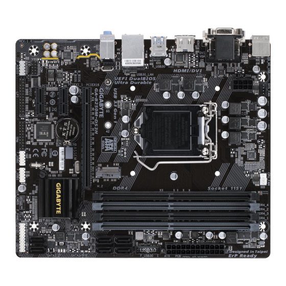
GA-B250M-DS3H Motherboard Layout SYS_FAN CPU_FAN KB_MS_USB ATX_12V_2X4 LGA1151 R_USB30 USB30_LAN GA-B250M-DS3H AUDIO ® Realtek SATA3 1 0 GbE LAN PCIEX16 CODEC B_BIOS Intel B250 ® PCIEX1_1 SATA3 5 4 M_BIOS ® Super PCIEX1_2 F_AUDIO CLR_CMOS SPDIF_O F_USB2 F_USB1 F_PANEL Box Contents… -
Page 5
Chapter 1 Hardware Installation Installation Precautions The motherboard contains numerous delicate electronic circuits and components which can become damaged as a result of electrostatic discharge (ESD). Prior to installation, carefully read the user’s manual and follow these procedures: Prior to installation, make sure the chassis is suitable for the motherboard. Prior to installation, do not remove or break motherboard S/N (Serial Number) sticker or warranty sticker provided by your dealer. -
Page 6
Support for non-ECC Un-buffered DIMM 1Rx8/2Rx8/1Rx16 memory modules * To support 2400 MHz or XMP memory, you must install a 7th generation processor. (Go to GIGABYTE’s website for the latest supported memory speeds and memory modules.) Onboard Integrated Graphics Processor-Intel ®… -
Page 7
Chipset: 6 x USB 3.1 Gen 1 ports (4 ports on the back panel, 2 ports available through the internal USB header) 6 x USB 2.0/1.1 ports (2 ports on the back panel, 4 ports available through the internal USB headers) Internal 1 x 24-pin ATX main power connector Connectors… -
Page 8
Form Factor Micro ATX Form Factor; 22.6cm x 19.3cm prior notice. Please visit GIGABYTE’s website for support lists of CPU, memory modules, SSDs, and M.2 devices. Please visit the SupportUtility List page on GIGABYTE’s website to download the latest version of apps. -
Page 9
Make sure that the motherboard supports the memory. It is recommended that memory of the same capacity, brand, speed, and chips be used. (Go to GIGABYTE’s website for the latest supported memory speeds and memory modules.) Always turn off the computer and unplug the power cord from the power outlet before installing the memory to prevent hardware damage. -
Page 10
The four memory sockets are divided into two channels and each channel has two memory sockets as following: Channel A: DDR4_2, DDR4_4 Channel B: DDR4_1, DDR4_3 DDR4_4 DDR4_2 DDR4_3 DDR4_1 2 Modules DS/SS DS/SS DS/SS DS/SS 4 Modules DS/SS DS/SS DS/SS DS/SS (SS=Single-Sided, DS=Double-Sided, «- -«=No Memory) -
Page 11
The line out jack. Use this audio jack for a headphone or 2-channel speaker. This jack can be used to Mic In (Pink) The Mic in jack. multi-channel audio feature through the audio driver. Please visit GIGABYTE’s website for more software information. device and then remove it from the motherboard. -
Page 12
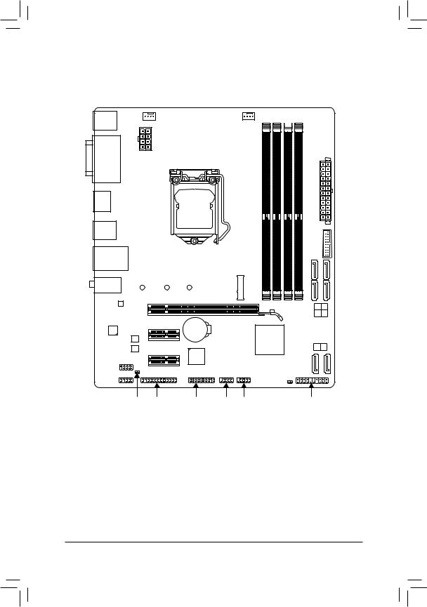
Internal Connectors ATX_12V_2X4 SPDIF_O F_USB30 CPU_FAN F_USB1/F_USB2 SYS_FAN SATA3 0/1/2/3/4/5 M2Q_32G F_PANEL F_AUDIO CLR_CMOS Read the following guidelines before connecting external devices: First make sure your devices are compliant with the connectors you wish to connect. Before installing the devices, be sure to turn off the devices and your computer. Unplug the power cord from the power outlet to prevent damage to the devices. -
Page 13
1/2) ATX_12V_2X4/ATX (2×4 12V Power Connector and 2×12 Main Power Connector) With the use of the power connector, the power supply can supply enough stable power to all the components off and all devices are properly installed. The power connector possesses a foolproof design. Connect the power supply cable to the power connector in the correct orientation. -
Page 14
3/4) CPU_FAN/SYS_FAN (Fan Headers) All fan headers on this motherboard are 4-pin. Most fan headers possess a foolproof insertion design. When connecting a fan cable, be sure to connect it in the correct orientation (the black connector wire is the ground wire). The speed control function requires the use of a fan with fan speed control design. For optimum heat dissipation, it is recommended that a system fan be installed inside the chassis. -
Page 15
6) M2Q_32G (M.2 Socket 3 Connector) The M.2 connector supports M.2 SATA SSDs and M.2 PCIe SSDs. Follow the steps below to correctly install an M.2 SSD in the M.2 connector. Step 1: Use a screw driver to unfasten the screw and nut from the motherboard. Locate the proper mounting hole Step 2: Slide the M.2 SSD into the connector at an angle. -
Page 16
7) F_PANEL (Front Panel Header) Connect the power switch, reset switch, speaker, chassis intrusion switch/sensor and system status indicator on the chassis to this header according to the pin assignments below. Note the positive and negative pins before connecting the cables. PLED/PWR_LED (Power LED): Power LED Power Switch… -
Page 17
9) SPDIF_O (S/PDIF Out Header) This header supports digital S/PDIF Out and connects a S/PDIF digital audio cable (provided by expansion cards) for digital audio output from your motherboard to certain expansion cards like graphics cards and sound cards. For example, some graphics cards may require you to use a S/PDIF digital audio cable for digital audio output from your motherboard to your graphics card if you wish to connect an HDMI display to the graphics card and have digital audio output from the HDMI display at the same time. -
Page 18
12) COM (Serial Port Header) The COM header can provide one serial port via an optional COM port cable. For purchasing the optional COM port cable, please contact the local dealer. Pin No. Pin No. NDCD- NDSR- NSIN NRTS- NSOUT NCTS- NDTR- NRI-… -
Page 19
15) BAT (Battery) in the CMOS when the computer is turned off. Replace the battery when the battery voltage drops to a low level, or the CMOS values may not be accurate or may be lost. You may clear the CMOS values by removing the battery: 1. -
Page 20
To access the BIOS Setup program, press the <Delete> key during the POST when the power is turned on. To upgrade the BIOS, use either the GIGABYTE Q-Flash or @BIOS utility. Q-Flash allows the user to quickly and easily upgrade or back up BIOS without entering the operating system. -
Page 21
M.I.T. Whether the system will work stably with the overclock/overvoltage settings you made is dependent on your overall and reduce the useful life of these components. This page is for advanced users only and we recommend you not to alter the default settings to prevent system instability or other unexpected results. (Inadequately altering the settings may result in system’s failure to boot. -
Page 22
AVX Offset (Note) AVX offset is the negative offset of AVX ratio. Uncore Ratio Allows you to set the CPU Uncore ratio. The adjustable range is dependent on the CPU being used. Uncore Frequency Displays the current CPU Uncore frequency. CPU Flex Ratio Override Enables or disables the CPU Flex Ratio. -
Page 23
C6/C7 State Support (Note 1) Allows you to determine whether to let the CPU enter C6/C7 mode in system halt state. When enabled, the CPU core frequency and voltage will be reduced during system halt state to decrease power consumption. The C6/C7 state is a more enhanced power-saving state than C3. -
Page 24
Memory Odd Ratio(100/133 or 200/266) Allows you to manually adjust the memory reference clock. (Default: Auto) Memory Frequency (MHz) is the memory frequency that is automatically adjusted according to the System Memory Multiplier settings. Advanced Memory Settings (Note) , System Memory Multiplier, Memory Odd Ratio(100/133 or 200/266), Memory Frequency(Mhz) The settings above are synchronous to those under the same items on the Advanced Frequency Settings menu. -
Page 25
Channel A/B Memory Sub Timings This sub-menu provides memory timing settings for each channel of memory. The respective timing setting Memory Timing Mode is set to Manual or Advanced Manual. Note: Your system may become unstable or fail to boot after you make changes on the memory timings. If this occurs, please reset the board to default values by loading optimized defaults or clearing the CMOS values. -
Page 26
Smart Fan 5 Settings Monitor Allows you to select a target to monitor and to make further adjustment. (Default: CPU FAN) Fan Speed Control Allows you to determine whether to enable the fan speed control function and adjust the fan speed. Normal Allows the fan to run at different speeds according to the temperature. -
Page 27
System This section provides information on your motherboard model and BIOS version. You can also select the default language used by the BIOS and manually set the system time. Access Level Displays the current access level depending on the type of password protection used. (If no password is set, the default will display as Administrator.) The Administrator level allows you to make changes to all BIOS settings;… -
Page 28
A password is required for booting the system and for entering the BIOS Setup program. (Default) Full Screen LOGO Show Allows you to determine whether to display the GIGABYTE Logo at system startup. Disabled skips the GIGABYTE Logo when the system starts up. (Default: Enabled) Boot Option Priorities… -
Page 29
Fast Boot Enables or disables Fast Boot to shorten the OS boot process. Ultra Fast provides the fastest bootup speed. (Default: Disabled) SATA Support All Sata Devices All SATA devices are functional in the operating system and during the POST. (Default) Last Boot HDD Only Except for the previous boot drive, all SATA devices are disabled before the OS boot process completes. -
Page 30
LAN PXE Boot Option ROM Allows you to select whether to enable the legacy option ROM for the LAN controller. (Default: Disabled) CSM Support is set to Enabled. Storage Boot Option Control Allows you to select whether to enable the UEFI or legacy option ROM for the storage device controller. Do not launch Disables option ROM. -
Page 31
Peripherals Initial Display Output graphics. OnBoard LAN Controller Enables or disables the onboard LAN function. If you wish to install a 3rd party add-in network card instead of using the onboard LAN, set this item to Disabled. Ambient LED Enables or disables the onboard audio LED. (Default: On) Intel Platform Trust Technology (PTT) Enables or disables Intel ®… -
Page 32
Intel(R) Bios Guard Technology Enables or disables the Intel ® BIOS Guard feature, which protects the BIOS from malicious attacks. Network Stack Disables or enables booting from the network to install a GPT format OS, such as installing the OS from the Windows Deployment Services server. -
Page 33
SATA Controller(s) Enables or disables the integrated SATA controllers. (Default: Enabled) SATA Mode Selection Intel RST With Intel Optane System Acceleration Enables Intel ® Optane ™ Technology support for the SATA controllers. Serial ATA features such as Native Command Queuing and hot plug. (Default) Aggressive LPM Support Enables or disables the power saving feature, ALPM (Aggressive Link Power Management), for the Chipset SATA controllers. -
Page 34
Chipset (Note) VT-d Enables or disables Intel ® Virtualization Technology for Directed I/O. (Default: Enabled) Internal Graphics Enables or disables the onboard graphics function. (Default: Auto) DVMT Pre-Allocated Allows you to set the onboard graphics memory size. Options are: 32M~1024M. (Default: 32M) DVMT Total Gfx Mem Allows you to allocate the DVMT memory size of the onboard graphics. -
Page 35
Power Platform Power Management Enables or disables the Active State Power Management function (ASPM). (Default: Disabled) PEG ASPM Platform Power Management is set to Enabled. (Default: Enabled) PCH ASPM Platform Power Management is set to Enabled. (Default: Enabled) DMI ASPM Platform Power Management is set to Enabled. -
Page 36
Power On Password Set the password when Power On By Keyboard is set to Password. Press <Enter> on this item and set a password with up to 5 characters and then press <Enter> to accept. To turn on the system, enter the password and press <Enter>. Note: To cancel the password, press <Enter>… -
Page 37
Save & Exit Save & Exit Setup Press <Enter> on this item and select Yes. This saves the changes to the CMOS and exits the BIOS Setup program. Select No or press <Esc> to return to the BIOS Setup Main Menu. Exit Without Saving Press <Enter>… -
Page 38
You can click the Xpress Install button and «Xpress Install» will install all of the selected drivers. Or click the arrow icon to individually install the drivers you need. Please visit GIGABYTE’s website for more software information. — 38 -… -
Page 39
Contravention will be prosecuted. We believe that the information contained herein was accurate in all respects at the time of printing. GIGABYTE cannot, however, assume any responsibility for errors or omissions in this text. Also note that the information in this document is subject to change without notice and should not be construed as a commitment by GIGABYTE. -
Page 40
FCC Notice (U.S.A. Only) This equipment has been tested and found to comply with the limits for a Class B digital device, pursuant to Part 15 of the FCC Rules. These limits are designed to provide reasonable protection against harmful interference in a residential installation. -
Page 41
Contact Us GIGA-BYTE TECHNOLOGY CO., LTD. Address: No.6, Baoqiang Rd., Xindian Dist., New Taipei City 231, Taiwan TEL: +886-2-8912-4000, FAX: +886-2-8912-4005 Tech. and Non-Tech. Support (Sales/Marketing) : http://esupport.gigabyte.com WEB address (English): http://www.gigabyte.com WEB address (Chinese): http://www.gigabyte.tw GIGABYTE eSupport To submit a technical or non-technical (Sales/Marketing) question, please link to: http://esupport.gigabyte.com…
инструкцияGigabyte GA-B250M-DS3H

To reduce the impacts on global warming, the packaging materials of this product
are recyclable and reusable. GIGABYTE works with you to protect the environment.
For more product details, please visit GIGABYTE’s website.
User’s Manual
Rev. 1001
Посмотреть инструкция для Gigabyte GA-B250M-DS3H бесплатно. Руководство относится к категории Материнские платы, 7 человек(а) дали ему среднюю оценку 9.2. Руководство доступно на следующих языках: английский. У вас есть вопрос о Gigabyte GA-B250M-DS3H или вам нужна помощь? Задайте свой вопрос здесь
- GA-B250M-DS3H Motherboard Layout
- Chapter 1 Hardware Installation
- Chapter 2 BIOS Setup
- Chapter 3 Appendix
Главная
| Gigabyte | |
| GA-B250M-DS3H | GA-B250M-DS3H | |
| Материнская плата | |
| 4719331847265, 0889523007938, 7106784505946 | |
| английский | |
| Руководство пользователя (PDF), Инструкция по установке (PDF) |
Контроллеры хранения данных
| Поддерживаемые типы накопителей | HDD & SSD |
Память
| Поддерживаемые типы памяти | DDR4-SDRAM |
| Тип слотов памяти | DIMM |
| Количество слотов памяти | 4 |
| Каналы памяти | Dual-channel |
| без функции коррекции ошибок | Да |
| Поддерживаемые частоты памяти | 2133,2400 MHz |
| Поддерживаемые объемы модулей памяти | 1GB, 2GB, 4GB, 8GB, 16GB |
| Максимальная внутренняя память | 64 GB |
| Небуферизованная память | Да |
Свойства
| Поддерживаемые операционные системы Linux | Да |
| Поддерживаемые операционные системы Windows | Windows 10 Education, Windows 10 Education x64, Windows 10 Enterprise, Windows 10 Enterprise x64, Windows 10 Home, Windows 10 Home x64, Windows 10 Pro, Windows 10 Pro x64, Windows 7 Enterprise, Windows 7 Enterprise x64, Windows 7 Home Basic, Windows 7 Home Basic x64, Windows 7 Home Premium, Windows 7 Home Premium x64, Windows 7 Professional, Windows 7 Professional x64, Windows 7 Starter, Windows 7 Starter x64, Windows 7 Ultimate, Windows 7 Ultimate x64, Windows 8, Windows 8 Enterprise, Windows 8 Enterprise x64, Windows 8 Pro, Windows 8 Pro x64, Windows 8 x64 |
| Комплектующие для | ПК |
| Семейство чипсета материнской платы | Intel |
| Формат материнской платы | Микро ATX |
| Выходные звуковые каналы | 7.1 канала |
| Чипсет материнской платы | Intel® B250 |
| Тип источника питания | ATX |
Процессор
| Производитель процессора | Intel |
| Совместимые серии процессоров | Intel Celeron, Intel Pentium |
| Сокет процессора | LGA 1151 (разъем H4) |
| Серии Intel® Core i3/i5/i7/i9 | i3-xxx, i5-xxx, i7-xxx |
Внутренние порты
| Разъемы USB 2.0 | 6 |
| Разъемы USB 3.2 Gen 1 (3.1 Gen 1) | 6 |
| Разъемы USB 3.2 Gen 2 (3.1 Gen 2) | 0 |
| Разъем выхода S/PDIF | Да |
| Разъем вентилятора центрального процессора | Да |
| Количество параллельных разъемов ATA (PATA) | 0 |
| Аудиоразъем передней панели | Да |
| TPM коннектор | Да |
| Количество разъемов SATA II | 0 |
| Количество разъемов SATA III | 6 |
| EPS разъем питания (8-конт) | Да |
| Разъем передней панели | Да |
Порты на задней панели
| Количество портов USB 2.0 | 2 |
| Количество портов USB 3.2 Gen 1 (3.1 Gen 1) Type-A | 4 |
| Количество портов USB 3.2 Gen 1 (3.1 Gen 1) Type-С | 0 |
| Количество портов USB 3.2 Gen 2 (3.1 Gen 2) Type-A | 0 |
| Количество портов USB 3.2 Gen 2 (3.1 Gen 2) Type-С | 0 |
| Количество портов Ethernet LAN ( RJ-45) | 1 |
| Количество портов eSATA | 0 |
| Количество портов PS/2 | 1 |
| Порты FireWire | 0 |
| Линейные выходы наушников | 1 |
| Линейный вход микрофона | Да |
| Количество портов VGA (D-Sub) | 1 |
| Количество HDMI портов | 1 |
| Количество портов DVI-D | 1 |
Сеть
| Подключение Ethernet | Да |
| Тип Ethernet интерфейса | Быстрый Ethernet |
Вес и размеры
| Ширина | 193 mm |
| Глубина | 226 mm |
BIOS
| Тип BIOS | UEFI AMI |
| Размер памяти BIOS | 128 Mbit |
| Версия ACPI | 5.0 |
| Перемычка Clear CMOS | Да |
Особые свойства процессора
| Intel® Optane™ Memory Ready | Да |
| экстремальный профиль памяти Intel | Да |
Слоты расширения
| PCI Express x1 слоты | 2 |
| PCI Express x16 слоты | 1 |
| Количество M.2 (M) слотов | 1 |
Логистические данные
| Код гармонизированной системы описания (HS) | 84733020 |
показать больше
Не можете найти ответ на свой вопрос в руководстве? Вы можете найти ответ на свой вопрос ниже, в разделе часто задаваемых вопросов о Gigabyte GA-B250M-DS3H.
Не нашли свой вопрос? Задайте свой вопрос здесь
-
Драйверы
22
-
Инструкции по эксплуатации
2
Языки:

Gigabyte GA-B250M-DS3H инструкция по эксплуатации
(2 страницы)
- Языки:Английский, Арабский, Болгарский, Венгерский, Вьетнамский, Греческий, Иврит, Индонезийский, Испанский, Итальянский, Китайский, Корейский, Немецкий, Персидский, Польский, Португальский, Румынский, Русский, Сербский, Тайский, Турецкий, Французский, Хорватский, Чешский, Японский
-
Тип:
PDF -
Размер:
8.98 MB -
Описание:
Multilingual Installation Guide

На NoDevice можно скачать инструкцию по эксплуатации для Gigabyte GA-B250M-DS3H. Руководство пользователя необходимо для ознакомления с правилами установки и эксплуатации Gigabyte GA-B250M-DS3H. Инструкции по использованию помогут правильно настроить Gigabyte GA-B250M-DS3H, исправить ошибки и выявить неполадки.
 Loading…
![]()
GA-B250M-DS3H
User’s Manual
Rev. 1001
For more product details, please visit GIGABYTE’s website.
To reduce the impacts on global warming, the packaging materials of this product are recyclable and reusable. GIGABYTE works with you to protect the environment.

Motherboard
GA-B250M-DS3H
Motherboard
GA-B250M-DS3H
Nov. 18, 2016
Nov. 18, 2016
Copyright
© 2016 GIGA-BYTE TECHNOLOGY CO., LTD. All rights reserved.
The trademarks mentioned in this manual are legally registered to their respective owners.
Disclaimer
Information in this manual is protected by copyright laws and is the property of GIGABYTE.
ChangestothespecificationsandfeaturesinthismanualmaybemadebyGIGABYTEwithoutpriornotice.
No part of this manual may be reproduced, copied, translated, transmitted, or published in any form or by any means without GIGABYTE’s prior written permission.
In order to assist in the use of this product, carefully read the User’s Manual.
For product-related information, check on our website at: http://www.gigabyte.com
Identifying Your Motherboard Revision
The revision number on your motherboard looks like this: «REV: X.X.» For example, «REV: 1.0» means the revision of the motherboard is 1.0. Check your motherboard revision before updating motherboard BIOS, drivers, or when looking for technical information.
Example:

Table of Contents
|
GA-B250M-DS3H Motherboard Layout………………………………………………………………… |
4 |
|
|
Chapter 1 Hardware Installation………………………………………………………………………….. |
5 |
|
|
1-1 |
Installation Precautions…………………………………………………………………………. |
5 |
|
1-2 |
Product Specifications………………………………………………………………………….. |
6 |
|
1-3 |
Installing the CPU………………………………………………………………………………… |
9 |
|
1-4 |
Installing the Memory……………………………………………………………………………. |
9 |
|
1-5 Installing an Expansion Card……………………………………………………………….. |
10 |
|
|
1-6 |
Back Panel Connectors………………………………………………………………………. |
10 |
|
1-7 |
Internal Connectors……………………………………………………………………………. |
12 |
|
Chapter 2 BIOS Setup……………………………………………………………………………………… |
20 |
|
|
2-1 |
Startup Screen…………………………………………………………………………………… |
20 |
|
2-2 |
M.I.T…………………………………………………………………………………………………. |
21 |
|
2-3 |
System……………………………………………………………………………………………… |
27 |
|
2-4 |
BIOS………………………………………………………………………………………………… |
28 |
|
2-5 |
Peripherals………………………………………………………………………………………… |
31 |
|
2-6 |
Chipset……………………………………………………………………………………………… |
34 |
|
2-7 |
Power……………………………………………………………………………………………….. |
35 |
|
2-8 |
Save & Exit……………………………………………………………………………………….. |
37 |
|
Chapter 3 Appendix…………………………………………………………………………………………. |
38 |
|
|
Drivers Installation……………………………………………………………………………………….. |
38 |
|
|
Regulatory Statements…………………………………………………………………………………. |
39 |
|
|
Contact Us………………………………………………………………………………………………….. |
41 |
— 3 —
GA-B250M-DS3H Motherboard Layout
|
KB_MS_USB |
SYS_FAN |
CPU_FAN |
DDR4 4 DDR4 2 DDR4 3 |
||
|
ATX_12V_2X4 |
|||||
|
DVI VGA |
LGA1151 |
||||
|
HDMI |
|||||
|
R_USB30 |
|||||
|
USB30_LAN |
GA-B250M-DS3H |
||||
|
AUDIO |
32G |
||||
|
80 |
60 |
42 |
M2Q |
||
|
Realtek® |
|||||
|
GbE LAN |
|||||
|
CODEC |
PCIEX16 |
BAT |
|||
|
B_BIOS |
PCIEX1_1 |
Intel® B250 |
|||
|
M_BIOS |
iTE® |
||||
|
COM |
PCIEX1_2 |
Super I/O |
|||
|
F_AUDIO |
|||||
|
CLR_CMOS |
|||||
|
SPDIF_O |
LPT |
TPM F_USB2 F_USB1 |
DDR4_1
ATX
F_USB30
SATA3 1 0 3 2
SATA3 5 4
F_PANEL
Box Contents
|
55 |
GA-B250M-DS3H otherboard |
||
|
55 |
Motherboard driver disk |
55 |
Two SATA cables |
|
55 |
User’s Manual |
55 |
I/O Shield |
* The box contents above are for reference only and the actual items shall depend on the product package you obtain. The box contents are subject to change without notice.
— 4 —

Chapter 1 Hardware Installation
1-1 Installation Precautions
The motherboard contains numerous delicate electronic circuits and components which can become damaged as a result of electrostatic discharge (ESD). Prior to installation, carefully read the user’s manual and follow these procedures:
•• Prior to installation, make sure the chassis is suitable for the motherboard.
•• Prior to installation, do not remove or break motherboard S/N (Serial Number) sticker or warranty sticker provided by your dealer. These stickers are required for warranty validation.
•• Always remove the AC power by unplugging the power cord from the power outlet before installing or removing the motherboard or other hardware components.
•• When connecting hardware components to the internal connectors on the motherboard, make sure they are connected tightly and securely.
•• When handling the motherboard, avoid touching any metal leads or connectors.
•• It is best to wear an electrostatic discharge (ESD) wrist strap when handling electronic components such as a motherboard, CPU or memory. If you do not have an ESD wrist strap, keep your hands dry and first touch a metal object to eliminate static electricity.
•• Prior to installing the motherboard, please have it on top of an antistatic pad or within an electrostatic shielding container.
•• Before connecting or unplugging the power supply cable from the motherboard, make sure the power supply has been turned off.
•• Before turning on the power, make sure the power supply voltage has been set according to the local voltage standard.
•• Before using the product, please verify that all cables and power connectors of your hardware components are connected.
•• To prevent damage to the motherboard, do not allow screws to come in contact with the motherboard circuit or its components.
•• Make sure there are no leftover screws or metal components placed on the motherboard or within the computer casing.
•• Do not place the computer system on an uneven surface.
•• Do not place the computer system in a high-temperature or wet environment.
•• Turning on the computer power during the installation process can lead to damage to system components as well as physical harm to the user.
•• If you are uncertain about any installation steps or have a problem related to the use of the product, please consult a certified computer technician.
•• If you use an adapter, extension power cable, or power strip, ensure to consult with its installation and/or grounding instructions.
— 5 —
|
1-2 |
Product Specifications |
|
|
CPU |
Support for 7th and 6th generation Intel® Core™ i7 processors/Intel® Core™ i5 |
|
|
processors/Intel® Core™ i3 processors/Intel® Pentium® processors/Intel® Celeron® |
||
|
processors in the LGA1151 package |
||
|
(Go to GIGABYTE’s website for the latest CPU support list.) |
||
|
L3 cache varies with CPU |
||
|
Chipset |
Intel® B250 Express Chipset |
|
|
Memory |
4 x DDR4 DIMM sockets supporting up to 64 GB of system memory |
|
|
* Due to a Windows 32-bit operating system limitation, when more than 4 GB of physical |
||
|
memory is installed, the actual memory size displayed will be less than the size of |
||
|
the physical memory installed. |
Dual channel memory architecture
Support for DDR4 2400/2133 MHz memory modules
Support for ECC Un-buffered DIMM 1Rx8/2Rx8 memory modules (operate in non-ECC mode)
|
Support for non-ECC Un-buffered DIMM 1Rx8/2Rx8/1Rx16 memory modules |
|
|
Support for Extreme Memory Profile (XMP) memory modules |
|
|
* To support 2400 MHz or XMP memory, you must install a 7th generation processor. |
|
|
(Go to GIGABYTE’s website for the latest supported memory speeds and memory |
|
|
modules.) |
|
|
Onboard |
Integrated Graphics Processor-Intel® HD Graphics support: |
|
Graphics |
— 1 x D-Sub port, supporting a maximum resolution of 1920×1200@60 Hz |
|
— 1 x DVI-D port, supporting a maximum resolution of 1920×1200@60 Hz |
|
|
* The DVI-D port does not support D-Sub connection by adapter. |
|
|
— 1 x HDMI port, supporting a maximum resolution of 4096×2160@24 Hz |
|
|
* Support for HDMI 1.4 version. |
|
|
Support for up to 3 displays at the same time |
|
|
Maximum shared memory of 1 GB |
|
Audio |
Realtek® ALC887 codec |
|
|
High Definition Audio |
||
|
2/4/5.1/7.1-channel |
*To configure 7.1-channel audio, you have to use an HD front panel audio module and enable the multi-channel audio feature through the audio driver.
Support for S/PDIF Out
|
LAN |
Realtek® GbE LAN chip (10/100/1000 Mbit) |
||
|
Expansion Slots |
1 x PCI Express x16 slot, running at x16 |
||
|
2 x PCI Express x1 slots |
|||
|
(All of the PCI Express slots conform to PCI Express 3.0 standard.) |
|||
|
Storage Interface |
Chipset: |
||
|
— |
1 x M.2 connector (Socket 3, M key, type 2242/2260/2280 SATA and PCIe |
||
|
x4/x2 SSD support) |
|||
|
— |
6 x SATA 6Gb/s connectors |
||
|
* Refer to «1-7 Internal Connectors,» for the installation notices for the M.2 and SATA |
|||
|
connectors. |
— 6 —
|
USB |
Chipset: |
|
|
— 6 x USB 3.1 Gen 1 ports (4 ports on the back panel, 2 ports available through |
||
|
the internal USB header) |
||
|
— 6 x USB 2.0/1.1 ports (2 ports on the back panel, 4 ports available through |
||
|
the internal USB headers) |
||
|
Internal |
1 x 24-pin ATX main power connector |
|
|
Connectors |
1 x 8-pin ATX 12V power connector |
|
|
1 x M.2 Socket 3 connector |
||
|
6 x SATA 6Gb/s connectors |
||
|
1 x CPU fan header |
||
|
1 x system fan header |
||
|
1 x front panel header |
||
|
1 x front panel audio header |
||
|
1 x S/PDIF Out header |
||
|
1 x USB 3.1 Gen 1 header |
||
|
2 x USB 2.0/1.1 headers |
||
|
1 x Trusted Platform Module (TPM) header |
||
|
1 x serial port header |
||
|
1 x parallel port header |
||
|
1 x Clear CMOS jumper |
||
|
Back Panel |
1 x PS/2 keyboard/mouse port |
|
|
Connectors |
1 x D-Sub port |
|
|
1 x DVI-D port |
||
|
1 x HDMI port |
||
|
4 x USB 3.1 Gen 1 ports |
||
|
2 x USB 2.0/1.1 ports |
||
|
1 x RJ-45 port |
||
|
3 x audio jacks (Line In, Line Out, Mic In) |
||
|
I/O Controller |
iTE® I/O Controller Chip |
|
|
Hardware |
Voltage detection |
|
|
Monitor |
Temperature detection |
|
|
Fan speed detection |
||
|
Overheating warning |
||
|
Fan fail warning |
||
|
Fan speed control |
||
|
* Whether the fan speed control function is supported will depend on the fan you install. |
||
|
BIOS |
2 x 64 Mbit flash |
|
|
Use of licensed AMI UEFI BIOS |
||
|
Support for DualBIOS™ |
||
|
PnP 1.0a, DMI 2.7, WfM 2.0, SM BIOS 2.7, ACPI 5.0 |
— 7 —
|
Unique Features |
Support for APP Center |
||
|
* Available applications in APP Center may vary by motherboard model. Supported |
|||
|
functionsofeachapplicationmayalsovarydependingonmotherboardspecifications. |
|||
|
— |
3D OSD |
||
|
— |
@BIOS |
||
|
— |
Ambient LED |
||
|
— |
AutoGreen |
||
|
— |
BIOS Setup |
||
|
— |
Color Temperature |
||
|
— |
Cloud Station |
||
|
— |
EasyTune |
||
|
— |
Fast Boot |
||
|
— |
Game Boost |
||
|
— |
ON/OFF Charge |
||
|
— |
Platform Power Management |
||
|
— |
Smart Backup |
||
|
— |
Smart Keyboard |
||
|
— |
Smart TimeLock |
||
|
— |
System Information Viewer |
||
|
— |
USB Blocker |
||
|
— |
V-Tuner |
||
|
Support for 3TB+ Unlock |
|||
|
Support for Q-Flash |
|||
|
Support for Xpress Install |
|||
|
Bundled |
Norton® Internet Security (OEM version) |
||
|
Software |
Intel® Optane™ Memory Ready |
||
|
cFosSpeed |
|||
|
Operating |
Support for Windows 10/8.1 64-bit |
||
|
System |
Support for Windows 7 32-bit/64-bit |
||
|
* Operating systems supported may vary depending on your processor model. |
|||
|
* Please download the «Windows USB Installation Tool» from GIGABYTE’s website and |
|||
|
install it before installing Windows 7. |
|||
|
Form Factor |
Micro ATX Form Factor; 22.6cm x 19.3cm |
*GIGABYTE reserves the right to make any changes to the product specifications and product-related information without prior notice.
Please visit GIGABYTE’s website for support lists of CPU, memory modules, SSDs, and M.2 devices.
Please visit the SupportUtility List page on GIGABYTE’s website to download the latest version of apps.
— 8 —
1-3 Installing the CPU
Read the following guidelines before you begin to install the CPU:
•• Make sure that the motherboard supports the CPU.
(Go to GIGABYTE’s website for the latest CPU support list.)
•• Always turn off the computer and unplug the power cord from the power outlet before installing the CPU to prevent hardware damage.
•• Locate the pin one of the CPU. The CPU cannot be inserted if oriented incorrectly. (Or you may locate the notches on both sides of the CPU and alignment keys on the CPU socket.)
•• Apply an even and thin layer of thermal grease on the surface of the CPU.
•• Do not turn on the computer if the CPU cooler is not installed, otherwise overheating and damage of the CPU may occur.
•• Set the CPU host frequency in accordance with the CPU specifications. It is not recommended that the system bus frequency be set beyond hardware specifications since it does not meet the standard requirements for the peripherals. If you wish to set the frequency beyond the standard specifications, please do so according to your hardware specifications including the CPU, graphics card, memory, hard drive, etc.
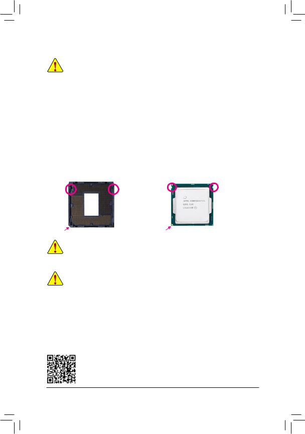
Installing the CPU
Locate the alignment keys on the motherboard CPU socket and the notches on the CPU.
|
LGA1151 CPU Socket |
LGA1151 CPU |
|
|
Alignment |
Notch |
Notch |
|
Alignment |
||
|
Key |
Key |
|
Pin One Corner of the CPU Socket |
Triangle Pin One Marking on the CPU |
Do not remove the CPU socket cover before inserting the CPU. It may pop off from the load plate automatically during the process of re-engaging the lever after you insert the CPU.
1-4 Installing the Memory
Read the following guidelines before you begin to install the memory:
•• Make sure that the motherboard supports the memory. It is recommended that memory of the same capacity, brand, speed, and chips be used.
(Go to GIGABYTE’s website for the latest supported memory speeds and memory modules.)
•• Always turn off the computer and unplug the power cord from the power outlet before installing the memory to prevent hardware damage.
•• Memory modules have a foolproof design. A memory module can be installed in only one direction. If you are unable to insert the memory, switch the direction.
Dual Channel Memory Configuration
This motherboard provides four memory sockets and supports Dual Channel Technology. After the memory is installed, the BIOS will automatically detect the specifications and capacity of the memory. Enabling Dual
Channel memory mode will double the original memory bandwidth.
Please visit GIGABYTE’s website for details on hardware installation.
— 9 —
The four memory sockets are divided into two channels and each channel has two memory sockets as following:
Channel A: DDR4_2, DDR4_4Channel B: DDR4_1, DDR4_3
Dual Channel Memory Configurations Table
|
DDR4_4 |
DDR4_2 |
DDR4_3 |
DDR4_1 |
|
|
2 Modules |
— — |
DS/SS |
— — |
DS/SS |
|
DS/SS |
— — |
DS/SS |
— — |
|
|
4 Modules |
DS/SS |
DS/SS |
DS/SS |
DS/SS |
(SS=Single-Sided, DS=Double-Sided, «- -«=No Memory)
Due to CPU limitations, read the following guidelines before installing the memory in Dual Channel mode.
1.Dual Channel mode cannot be enabled if only one memory module is installed.
2.When enabling Dual Channel mode with two or four memory modules, it is recommended that memory of the same capacity, brand, speed, and chips be used.
1-5 Installing an Expansion Card
Read the following guidelines before you begin to install an expansion card:
•• Make sure the motherboard supports the expansion card. Carefully read the manual that came with your expansion card.
•• Always turn off the computer and unplug the power cord from the power outlet before installing an expansion card to prevent hardware damage.
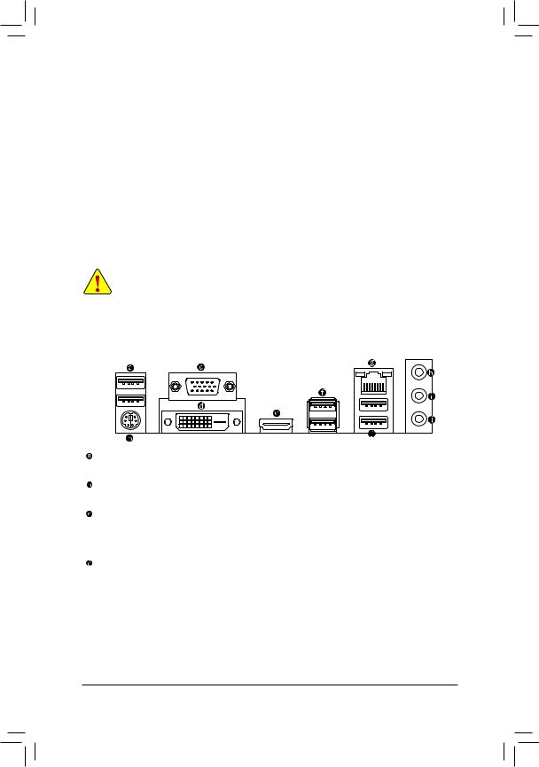
1-6 Back Panel Connectors
USB 2.0/1.1 Port
The USB port supports the USB 2.0/1.1 specification. Use this port for USB devices.
PS/2 Keyboard/Mouse Port
Use this port to connect a PS/2 mouse or keyboard.
D-Sub Port
The D-Sub port supports a 15-pin D-Sub connector and supports a maximum resolution of 1920×1200@60 Hz (the actual resolutions supported depend on the monitor being used). Connect a monitor that supports D-Sub connection to this port.
DVI-D Port (Note)
The DVI-Dport conforms tothe DVI-Dspecification and supportsamaximumresolutionof1920x1200@60Hz
(the actual resolutions supported depend on the monitor being used). Connect a monitor that supports DVI-D connection to this port.
(Note) The DVI-D port does not support D-Sub connection by adapter. — 10 —
![]()
HDMI Port
 The HDMI port is HDCP compliant and supports Dolby TrueHD and DTS HD


 Master Audio formats. It also supports up to 192KHz/16bit 8-channel LPCM audio output. You can use this port to connect your HDMI-supported monitor. The maximum supported resolution is 4096×2160@24 Hz, but the actual resolutions supported are dependent on the monitor being used.
•• To set up a triple-display configuration, you must install motherboard drivers in the operating 
 system first.
•• After installing the HDMI device, make sure to set the default sound playback device to HDMI. (The item name may differ depending on your operating system.)
USB 3.1 Gen 1 Port
The USB 3.1 Gen 1 port supports the USB 3.1 Gen 1 specification and is compatible to the USB 2.0 specification. Use this port for USB devices.
RJ-45 LAN Port
The Gigabit Ethernet LAN port provides Internet connection at up to 1 Gbps data rate. The following describes the states of the LAN port LEDs.
|
Connection/ |
Connection/Speed LED: |
Activity LED: |
|||||||||||||||||
|
Speed LED |
Activity LED |
||||||||||||||||||
|
State |
Description |
State |
Description |
||||||||||||||||
|
Orange |
1 Gbps data rate |
Blinking |
Data transmission or receiving is occurring |
||||||||||||||||
|
Green |
100 Mbps data rate |
Off |
No data transmission or receiving is occurring |
||||||||||||||||
|
Off |
10 Mbps data rate |
||||||||||||||||||
|
LAN Port |
|||||||||||||||||||
Line In (Blue)
The line in jack. Use this audio jack for line in devices such as an optical drive, walkman, etc.
Line Out (Green)
The line out jack. Use this audio jack for a headphone or 2-channel speaker. This jack can be used to connect front speakers in a 4/5.1/7.1-channel audio configuration.
Mic In (Pink)
The Mic in jack.
 To configure 7.1-channel audio, you have to use an HD front panel audio module and enable the
multi-channel audio feature through the audio driver. Please visit GIGABYTE’s website for more software information.
•• When removing the cable connected to a back panel connector, first remove the cable from your device and then remove it from the motherboard.
•• When removing the cable, pull it straight out from the connector. Do not rock it side to side to prevent an electrical short inside the cable connector.
— 11 —
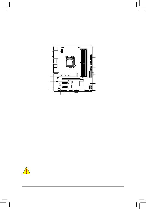
1-7 Internal Connectors
|
1 |
4 |
3 |
|||||
|
2 |
||||
|
10 |
||||
|
6 |
5 |
|||
|
15 |
5 |
|||
|
12 |
||||
|
8 |
7 |
|||
|
9 |
13 |
14 |
11 |
16 |
|
1) |
ATX_12V_2X4 |
9) |
SPDIF_O |
|
2) |
ATX |
10) |
F_USB30 |
|
3) |
CPU_FAN |
11) |
F_USB1/F_USB2 |
|
4) |
SYS_FAN |
12) |
COM |
|
5) |
SATA3 0/1/2/3/4/5 |
13) |
LPT |
|
6) |
M2Q_32G |
14) |
TPM |
|
7) |
F_PANEL |
15) |
BAT |
|
|
F_AUDIO |
16) |
CLR_CMOS |

Read the following guidelines before connecting external devices:
•• First make sure your devices are compliant with the connectors you wish to connect.
•• Before installing the devices, be sure to turn off the devices and your computer. Unplug the power cord from the power outlet to prevent damage to the devices.
•• After installing the device and before turning on the computer, make sure the device cable has been securely attached to the connector on the motherboard.
— 12 —
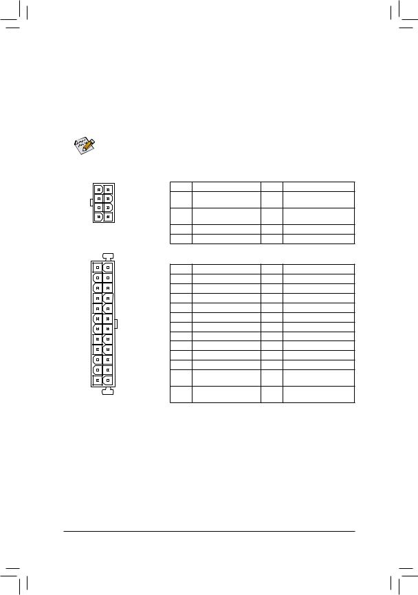
1/2) ATX_12V_2X4/ATX (2×4 12V Power Connector and 2×12 Main Power Connector)
With the use of the power connector, the power supply can supply enough stable power to all the components on the motherboard. Before connecting the power connector, first make sure the power supply is turned off and all devices are properly installed. The power connector possesses a foolproof design. Connect the power supply cable to the power connector in the correct orientation.
The 12V power connector mainly supplies power to the CPU. If the 12V power connector is not connected, the computer will not start.
To meet expansion requirements, it is recommended that a power supply that can withstand high power consumption be used (500W or greater). If a power supply is used that does not provide the required power, the result can lead to an unstable or unbootable system.
|
ATX_12V_2X4: |
|||||
|
8 |
4 |
Pin No. |
Definition |
Pin No. |
Definition |
|
1 |
GND (Only for 2×4-pin |
5 |
+12V (Only for 2×4-pin 12V) |
||
|
12V) |
|||||
|
5 |
1 |
2 |
GND (Only for 2×4-pin |
6 |
+12V (Only for 2×4-pin 12V) |
|
12V) |
|||||
|
ATX_12V_2X4 |
3 |
GND |
7 |
+12V |
|
|
4 |
GND |
8 |
+12V |
||
|
12 |
24 |
ATX: |
|||
|
Pin No. |
Definition |
Pin No. |
Definition |
||
|
1 |
3.3V |
13 |
3.3V |
||
|
2 |
3.3V |
14 |
-12V |
||
|
3 |
GND |
15 |
GND |
||
|
4 |
+5V |
16 |
PS_ON (soft On/Off) |
||
|
5 |
GND |
17 |
GND |
||
|
6 |
+5V |
18 |
GND |
||
|
7 |
GND |
19 |
GND |
||
|
8 |
Power Good |
20 |
NC |
||
|
9 |
5VSB (stand by +5V) |
21 |
+5V |
||
|
10 |
+12V |
22 |
+5V |
||
|
1 |
13 |
11 |
+12V (Only for 2×12-pin |
23 |
+5V (Only for 2×12-pin ATX) |
|
ATX) |
|||||
|
12 |
3.3V (Only for 2×12-pin |
24 |
GND (Only for 2×12-pin |
||
|
ATX |
ATX) |
ATX) |
— 13 —
Free Manuals for Gigabyte GA-B250M-DS3H (rev. 1.0)

Manufacturer:Gigabyte
Category:Computers & Peripherals
Device:Gigabyte GA-B250M-DS3H (rev. 1.0)
Name:Multilingual Installation Guide
Language:العربيةБългарскиČeštinaDeutschΕλληνικάEnglishEspañolفارسىFrançaisעבריתHrvatskiMagyarBahasa IndonesiaItaliano日本語한국어PolskiPortuguêsRomânăРусскийSrpskiไทยTürkçeTiếng Việt中文
Version:102
Pages:2
Size:8.98 MB
DescriptionGigabyte GA-B250M-DS3H (rev. 1.0) Multilingual Installation GuideView Gigabyte GA-B250M-DS3H (rev. 1.0) Multilingual Installation Guide 102 (العربية, Български, Čeština, Deutsch, Ελληνικά, English, Español, فارسى, Français, עברית, Hrvatski, Magyar, Bahasa Indonesia, Italiano, 日本語, 한국어, Polski, Português, Română, Русский, Srpski, ไทย, Türkçe, Tiếng Việt, 中文)

Manufacturer:Gigabyte
Category:Computers & Peripherals
Device:Gigabyte GA-B250M-DS3H (rev. 1.0)
Name:User’s Manual
Language:English
Version:1001
Pages:41
Size:11.75 MB

Manufacturer:Gigabyte
Category:Computers & Peripherals
Device:Gigabyte GA-B250M-DS3H (rev. 1.0)
Name:User’s Manual
Language:中文中文(简体)
Version:1001
Pages:42
Size:11.71 MB

Manufacturer:Gigabyte
Category:Computers & Peripherals
Device:Gigabyte GA-B250M-DS3H (rev. 1.0)
Name:User’s Manual
Language:中文中文(繁體)
Version:1002
Pages:42
Size:12.68 MB

Manufacturer:Gigabyte
Category:Computers & Peripherals
Device:Gigabyte GA-B250M-DS3H (rev. 1.0)
Name:Audio Setup Guide
Language:English
Pages:7
Size:1.47 MB