Atlas Copco
Oil-injected rotary screw compressors
GA 5, GA 7, GA 11
Instruction book
Atlas Copco
Oil-injected rotary screw compressors
GA 5, GA 7, GA 11
From following serial No. onwards: CAI 700 000
Instruction book
Original instructions
Copyright notice
Any unauthorized use or copying of the contents or any part thereof is prohibited.
This applies in particular to trademarks, model denominations, part numbers and drawings.
This instruction book is valid for CE as well as non-CE labelled machines. It meets the requirements for instructions specified by the applicable European directives as identified in the Declaration of Conformity.
2009 — 12
No. 2920 7090 51
Replaces No. 2920 7090 50
www.atlascopco.com
Instruction book
2
Table of contents
2
2.1
2.2
2.3
2.4
2.5
2.6
2.7
2.8
2.9
3
3.1
3.2
3.3
3.4
3.5
3.6
3.7
3.8
3.9
1
1.1
1.2
1.3
1.4
1.5
Safety precautions…………………………………………………………………………………………….7
S
AFETY ICONS
…………………………………………………………………………………………………………………..7
S
AFETY PRECAUTIONS
,
GENERAL
……………………………………………………………………………………………..7
S
AFETY PRECAUTIONS DURING INSTALLATION
……………………………………………………………………………….7
S
AFETY PRECAUTIONS DURING OPERATION
………………………………………………………………………………….9
S
AFETY PRECAUTIONS DURING MAINTENANCE OR REPAIR
……………………………………………………………….10
General description…………………………………………………………………………………………12
I
NTRODUCTION
…………………………………………………………………………………………………………………12
A
IR FLOW
………………………………………………………………………………………………………………………16
O
IL SYSTEM
……………………………………………………………………………………………………………………17
C
OOLING SYSTEM
……………………………………………………………………………………………………………..18
C
ONDENSATE SYSTEM
………………………………………………………………………………………………………..19
R
EGULATING SYSTEM
…………………………………………………………………………………………………………20
E
LECTRICAL SYSTEM
………………………………………………………………………………………………………….20
E
LECTRICAL DIAGRAMS
……………………………………………………………………………………………………….21
A
IR DRYER
……………………………………………………………………………………………………………………..24
Elektronikon® controller………………………………………………………………………………….26
E
LEKTRONIKON
®
REGULATOR
……………………………………………………………………………………………….26
C
ONTROL PANEL
………………………………………………………………………………………………………………27
I
CONS USED ON THE DISPLAY
………………………………………………………………………………………………..28
M
AIN SCREEN
………………………………………………………………………………………………………………….30
S
HUT
—
DOWN WARNING
………………………………………………………………………………………………………..30
S
HUT
—
DOWN
……………………………………………………………………………………………………………………32
S
ERVICE WARNING
…………………………………………………………………………………………………………….33
S
CROLLING THROUGH ALL SCREENS
………………………………………………………………………………………..35
C
ALLING UP OUTLET AND DEWPOINT TEMPERATURES
…………………………………………………………………….38
2920 7090 51
Instruction book
4
4.1
4.2
4.3
4.4
3.25
3.26
3.27
3.28
3.29
3.30
3.31
3.32
3.33
3.20
3.21
3.22
3.23
3.24
3.15
3.16
3.17
3.18
3.19
3.10
3.11
3.12
3.13
3.14
C
ALLING UP RUNNING HOURS
………………………………………………………………………………………………..39
C
ALLING UP MOTOR STARTS
…………………………………………………………………………………………………40
C
ALLING UP MODULE HOURS
…………………………………………………………………………………………………41
C
ALLING UP LOADING HOURS
………………………………………………………………………………………………..41
C
ALLING UP LOAD RELAY
…………………………………………………………………………………………………….41
C
ALLING UP
/
RESETTING THE SERVICE TIMER
……………………………………………………………………………..42
S
ELECTION BETWEEN LOCAL
,
REMOTE OR
LAN
CONTROL
………………………………………………………………43
C
ALLING UP
/
MODIFYING
CAN
ADDRESS CONTROL
……………………………………………………………………….43
C
ALLING UP
/
MODIFYING
IP, G
ATEWAY AND
S
UBNETMASK
………………………………………………………………45
C
ALLING UP
/
MODIFYING PRESSURE BAND SETTINGS
………………………………………………………………………47
M
ODIFYING THE PRESSURE BAND SELECTION
……………………………………………………………………………..48
C
ALLING UP
/
MODIFYING SERVICE TIMER SETTINGS
………………………………………………………………………..49
C
ALLING UP
/
MODIFYING THE UNIT OF TEMPERATURE
……………………………………………………………………..49
C
ALLING UP
/
MODIFYING UNIT OF PRESSURE
……………………………………………………………………………….50
A
CTIVATING AUTOMATIC RESTART AFTER VOLTAGE FAILURE
…………………………………………………………….50
S
ELECTION BETWEEN
Y-D
OR
DOL
STARTING
…………………………………………………………………………..50
C
ALLING UP MODIFYING LOAD DELAY TIME
…………………………………………………………………………………51
C
ALLING UP MODIFYING MINIMUM STOP TIME
………………………………………………………………………………51
A
CTIVATING PASSWORD PROTECTION
………………………………………………………………………………………52
A
CTIVATE LOAD
/
UNLOAD REMOTE PRESSURE SENSING
…………………………………………………………………..52
C
ALLING UP
/
MODIFYING PROTECTION SETTINGS
…………………………………………………………………………..53
T
EST SCREENS
………………………………………………………………………………………………………………..55
W
EB SERVER
………………………………………………………………………………………………………………….56
P
ROGRAMMABLE SETTINGS
…………………………………………………………………………………………………..64
Elektronikon® Graphic controller…………………………………………………………………….68
E
LEKTRONIKON
®
G
RAPHIC CONTROLLER
…………………………………………………………………………………..68
C
ONTROL PANEL
………………………………………………………………………………………………………………70
I
CONS USED
……………………………………………………………………………………………………………………71
M
AIN SCREEN
………………………………………………………………………………………………………………….74
2920 7090 51 3
Instruction book
7
7.1
7.2
7.3
6.1
6.2
6.3
6.4
5
5.1
5.2
5.3
6
4.10
4.11
4.12
4.13
4.14
4.15
4.16
4.17
4.18
4.5
4.6
4.7
4.8
4.9
C
ALLING UP MENUS
…………………………………………………………………………………………………………..76
I
NPUTS MENU
…………………………………………………………………………………………………………………..77
O
UTPUTS MENU
……………………………………………………………………………………………………………….78
C
OUNTERS
……………………………………………………………………………………………………………………..80
S
ERVICE MENU
………………………………………………………………………………………………………………..81
S
ETPOINT MENU
……………………………………………………………………………………………………………….85
E
VENT HISTORY MENU
………………………………………………………………………………………………………..87
M
ODIFYING GENERAL SETTINGS
……………………………………………………………………………………………..88
I
NFO MENU
……………………………………………………………………………………………………………………..89
W
EEK TIMER MENU
……………………………………………………………………………………………………………90
T
EST MENU
…………………………………………………………………………………………………………………….99
U
SER PASSWORD MENU
…………………………………………………………………………………………………….100
W
EB SERVER
………………………………………………………………………………………………………………..101
P
ROGRAMMABLE SETTINGS
…………………………………………………………………………………………………109
OSD oil/condensate separator (optional)………………………………………………………..113
OSD
UNIT
……………………………………………………………………………………………………………………113
O
PERATING AND MAINTENANCE INSTRUCTIONS
………………………………………………………………………….114
P
ICTOGRAPHS
……………………………………………………………………………………………………………….115
Installation…………………………………………………………………………………………………….117
D
IMENSION DRAWINGS
………………………………………………………………………………………………………117
I
NSTALLATION PROPOSAL
…………………………………………………………………………………………………..123
E
LECTRICAL CONNECTIONS
…………………………………………………………………………………………………126
P
ICTOGRAPHS
……………………………………………………………………………………………………………….131
Operating instructions…………………………………………………………………………………..133
I
NITIAL START
—
UP
…………………………………………………………………………………………………………….133
B
EFORE STARTING
…………………………………………………………………………………………………………..135
S
TARTING
……………………………………………………………………………………………………………………136
4 2920 7090 51
Instruction book
10
11
9
9.1
9.2
9.3
9.4
9.5
9.6
9.7
9.8
8.1
8.2
8.3
8.4
8.5
7.4
7.5
7.6
7.7
8
D
URING OPERATION
…………………………………………………………………………………………………………137
C
HECKING THE DISPLAY
…………………………………………………………………………………………………….139
S
TOPPING
……………………………………………………………………………………………………………………140
T
AKING OUT OF OPERATION
………………………………………………………………………………………………..141
Maintenance………………………………………………………………………………………………….143
P
REVENTIVE MAINTENANCE SCHEDULE
……………………………………………………………………………………143
O
IL SPECIFICATIONS
…………………………………………………………………………………………………………146
S
TORAGE AFTER INSTALLATION
……………………………………………………………………………………………146
S
ERVICE KITS
………………………………………………………………………………………………………………..147
D
ISPOSAL OF USED MATERIAL
……………………………………………………………………………………………..147
Adjustments and servicing procedures………………………………………………………….148
D
RIVE MOTOR
……………………………………………………………………………………………………………….148
A
IR FILTER
……………………………………………………………………………………………………………………148
O
IL AND OIL FILTER CHANGE
……………………………………………………………………………………………….149
O
IL SEPARATOR CHANGE
…………………………………………………………………………………………………..150
C
OOLERS
…………………………………………………………………………………………………………………….151
B
ELT TENSIONING AND REPLACEMENT
…………………………………………………………………………………….151
S
AFETY VALVES
……………………………………………………………………………………………………………..153
D
RYER MAINTENANCE INSTRUCTIONS
……………………………………………………………………………………..154
Problem solving…………………………………………………………………………………………….156
Technical data……………………………………………………………………………………………….159
11.1
11.2
11.3
11.4
11.5
11.6
R
EADINGS ON DISPLAY
……………………………………………………………………………………………………..159
E
LECTRIC CABLE SIZE
………………………………………………………………………………………………………160
S
ETTINGS FOR OVERLOAD RELAY AND FUSES
……………………………………………………………………………162
D
RYER SWITCHES
……………………………………………………………………………………………………………163
R
EFERENCE CONDITIONS AND LIMITATIONS
………………………………………………………………………………163
C
OMPRESSOR DATA
…………………………………………………………………………………………………………164
2920 7090 51 5
Instruction book
11.7
T
ECHNICAL DATA
E
LEKTRONIKON
®
CONTROLLER
……………………………………………………………………….169
14
15
12
13
Instructions for use……………………………………………………………………………………….171
Guidelines for inspection……………………………………………………………………………….172
Pressure equipment directives………………………………………………………………………173
Declaration of conformity………………………………………………………………………………174
6 2920 7090 51
Instruction book
1 Safety precautions
1.1
Safety icons
Explanation
Danger for life
Warning
Important note
1.2
Safety precautions, general
General precautions
1. The operator must employ safe working practices and observe all related work safety requirements and regulations.
2. If any of the following statements does not comply with the applicable legislation, the stricter of the two shall apply.
3. Installation, operation, maintenance and repair work must only be performed by authorized, trained, specialized personnel.
4. The compressor is not considered capable of producing air of breathing quality. For air of breathing quality, the compressed air must be adequately purified according to the applicable legislation and standards.
5. Before any maintenance, repair work, adjustment or any other non-routine checks, stop the compressor, press the emergency stop button, switch off the voltage and depressurize the compressor. In addition, the power isolating switch must be opened and locked.
6. Never play with compressed air. Do not apply the air to your skin or direct an air stream at people. Never use the air to clean dirt from your clothes. When using the air to clean equipment, do so with extreme caution and wear eye protection.
7. The owner is responsible for maintaining the unit in safe operating condition. Parts and accessories shall be replaced if unsuitable for safe operation.
8. It is not allowed to walk or stand on the roof of the compressor canopy.
1.3
Safety precautions during installation
All responsibility for any damage or injury resulting from neglecting these precautions, or non-observance of the normal caution and care required for installation, operation, maintenance and repair, even if not expressly stated, will be disclaimed by the manufacturer.
2920 7090 51 7
Instruction book
Precautions during installation
1. The machine must only be lifted using suitable equipment in accordance with the applicable safety regulations. Loose or pivoting parts must be securely fastened before lifting. It is strictly forbidden to dwell or stay in the risk zone under a lifted load. Lifting acceleration and deceleration must be kept within safe limits. Wear a safety helmet when working in the area of overhead or lifting equipment.
2. Place the machine where the ambient air is as cool and clean as possible. If necessary, install a suction duct. Never obstruct the air inlet. Care must be taken to minimize the entry of moisture at the inlet air.
3. Any blanking flanges, plugs, caps and desiccant bags must be removed before connecting the pipes.
4. Air hoses must be of correct size and suitable for the working pressure. Never use frayed, damaged or worn hoses. Distribution pipes and connections must be of the correct size and suitable for the working pressure.
5. The aspirated air must be free of flammable fumes, vapours and particles, e.g. paint solvents, that can lead to internal fire or explosion.
6. Arrange the air intake so that loose clothing worn by people cannot be sucked in.
7. Ensure that the discharge pipe from the compressor to the aftercooler or air net is free to expand under heat and that it is not in contact with or close to flammable materials.
8. No external force may be exerted on the air outlet valve; the connected pipe must be free of strain.
9. If remote control is installed, the machine must bear a clear sign stating: DANGER: This machine is remotely controlled and may start without warning.
The operator has to make sure that the machine is stopped and that the isolating switch is open and locked before any maintenance or repair. As a further safeguard, persons switching on remotely controlled machines shall take adequate precautions to ensure that there is no one checking or working on the machine. To this end, a suitable notice shall be affixed to the start equipment.
10. Air-cooled machines must be installed in such a way that an adequate flow of cooling air is available and that the exhausted air does not recirculate to the compressor air inlet or cooling air inlet.
11. The electrical connections must correspond to the applicable codes. The machines must be earthed and protected against short circuits by fuses in all phases. A lockable power isolating switch must be installed near the compressor.
12. On machines with automatic start/stop system or if the automatic restart function after voltage failure is activated, a sign stating «This machine may start without warning» must be affixed near the instrument panel.
13. In multiple compressor systems, manual valves must be installed to isolate each compressor. Non-return valves (check valves) must not be relied upon for isolating pressure systems.
14. Never remove or tamper with the safety devices, guards or insulation fitted on the machine. Every pressure vessel or auxiliary installed outside the machine to contain air above atmospheric pressure must be protected by a pressure-relieving device or devices as required.
15. Piping or other parts with a temperature in excess of 80˚C (176˚F) and which may be accidentally touched by personnel in normal operation must be guarded or insulated. Other high-temperature piping must be clearly marked.
16. For water-cooled machines, the cooling water system installed outside the machine has to be protected by a safety device with set pressure according to the maximum cooling water inlet pressure.
17. If the ground is not level or can be subject to variable inclination, consult the manufacturer.
Also consult following safety precautions: Safety precautions during operation
and Safety precautions during maintenance .
These precautions apply to machinery processing or consuming air or inert gas.
Processing of any other gas requires additional safety precautions typical to the application which are not included herein.
Some precautions are general and cover several machine types and equipment; hence some statements may not apply to your machine.
8 2920 7090 51
Instruction book
1.4
Safety precautions during operation
All responsibility for any damage or injury resulting from neglecting these precautions, or non-observance of the normal caution and care required for installation, operation, maintenance and repair, even if not expressly stated, will be disclaimed by the manufacturer.
Precautions during operation
1. Never touch any piping or components of the compressor during operation.
2. Use only the correct type and size of hose end fittings and connections. When blowing through a hose or air line, ensure that the open end is held securely. A free end will whip and may cause injury. Make sure that a hose is fully depressurized before disconnecting it.
3. Persons switching on remotely controlled machines shall take adequate precautions to ensure that there is no one checking or working on the machine. To this end, a suitable notice shall be affixed to the remote start equipment.
4. Never operate the machine when there is a possibility of taking in flammable or toxic fumes, vapours or particles.
5. Never operate the machine below or in excess of its limit ratings.
6. Keep all bodywork doors shut during operation. The doors may be opened for short periods only, e.g. to carry out routine checks. Wear ear protectors when opening a door.
7. People staying in environments or rooms where the sound pressure level reaches or exceeds 90 dB(A) shall wear ear protectors.
8. Periodically check that:
• All guards are in place and securely fastened
• All hoses and/or pipes inside the machine are in good condition, secure and not rubbing
• There are no leaks
• All fasteners are tight
• All electrical leads are secure and in good order
• Safety valves and other pressure-relief devices are not obstructed by dirt or paint
• Air outlet valve and air net, i.e. pipes, couplings, manifolds, valves, hoses, etc. are in good repair, free of wear or abuse
9. If warm cooling air from compressors is used in air heating systems, e.g. to warm up a workroom, take precautions against air pollution and possible contamination of the breathing air.
10. Do not remove any of, or tamper with, the sound-damping material.
11. Never remove or tamper with the safety devices, guards or insulations fitted on the machine. Every pressure vessel or auxiliary installed outside the machine to contain air above atmospheric pressure shall be protected by a pressure-relieving device or devices as required.
Also consult following safety precautions: Safety precautions during installation
and Safety precautions during maintenance .
These precautions apply to machinery processing or consuming air or inert gas.
Processing of any other gas requires additional safety precautions typical to the application which are not included herein.
Some precautions are general and cover several machine types and equipment; hence some statements may not apply to your machine.
2920 7090 51 9
Instruction book
1.5
Safety precautions during maintenance or repair
All responsibility for any damage or injury resulting from neglecting these precautions, or non-observance of the normal caution and care required for installation, operation, maintenance and repair, even if not expressly stated, will be disclaimed by the manufacturer.
Precautions during maintenance or repair
1. Always use the correct safety equipment (such as safety glasses, gloves, safety shoes, etc.).
2. Use only the correct tools for maintenance and repair work.
3. Use only genuine spare parts.
4. All maintenance work shall only be undertaken when the machine has cooled down.
5. A warning sign bearing a legend such as «work in progress; do not start» shall be attached to the starting equipment.
6. Persons switching on remotely controlled machines shall take adequate precautions to ensure that there is no one checking or working on the machine. To this end, a suitable notice shall be affixed to the remote start equipment.
7. Close the compressor air outlet valve before connecting or disconnecting a pipe.
8. Before removing any pressurized component, effectively isolate the machine from all sources of pressure and relieve the entire system of pressure.
9. Never use flammable solvents or carbon tetrachloride for cleaning parts. Take safety precautions against toxic vapours of cleaning liquids.
10. Scrupulously observe cleanliness during maintenance and repair. Keep dirt away by covering the parts and exposed openings with a clean cloth, paper or tape.
11. Never weld or perform any operation involving heat near the oil system. Oil tanks must be completely purged, e.g. by steam-cleaning, before carrying out such operations. Never weld on, or in any way modify, pressure vessels.
12. Whenever there is an indication or any suspicion that an internal part of a machine is overheated, the machine shall be stopped but no inspection covers shall be opened before sufficient cooling time has elapsed; this to avoid the risk of spontaneous ignition of the oil vapour when air is admitted.
13. Never use a light source with open flame for inspecting the interior of a machine, pressure vessel, etc.
14. Make sure that no tools, loose parts or rags are left in or on the machine.
15. All regulating and safety devices shall be maintained with due care to ensure that they function properly.
They may not be put out of action.
16. Before clearing the machine for use after maintenance or overhaul, check that operating pressures, temperatures and time settings are correct. Check that all control and shut-down devices are fitted and that they function correctly. If removed, check that the coupling guard of the compressor drive shaft has been reinstalled.
17. Every time the separator element is renewed, examine the discharge pipe and the inside of the oil separator vessel for carbon deposits; if excessive, the deposits should be removed.
18. Protect the motor, air filter, electrical and regulating components, etc. to prevent moisture from entering them, e.g. when steam-cleaning.
19. Make sure that all sound-damping material and vibration dampers, e.g. damping material on the bodywork and in the air inlet and outlet systems of the compressor, is in good condition. If damaged, replace it by genuine material from the manufacturer to prevent the sound pressure level from increasing.
20. Never use caustic solvents which can damage materials of the air net, e.g. polycarbonate bowls.
21.
The following safety precautions are stressed when handling refrigerant:
• Never inhale refrigerant vapours. Check that the working area is adequately ventilated; if required, use breathing protection.
10 2920 7090 51
Instruction book
• Always wear special gloves. In case of refrigerant contact with the skin, rinse the skin with water. If liquid refrigerant contacts the skin through clothing, never tear off or remove the latter; flush abundantly with fresh water over the clothing until all refrigerant is flushed away; then seek medical first aid.
Also consult following safety precautions: Safety precautions during installation
and Safety precautions during operation .
These precautions apply to machinery processing or consuming air or inert gas.
Processing of any other gas requires additional safety precautions typical to the application which are not included herein.
Some precautions are general and cover several machine types and equipment; hence some statements may not apply to your machine.
2920 7090 51 11
Instruction book
2 General description
2.1
Introduction
General
GA 5 up to GA 11 are single-stage, oil-injected screw compressors driven by an electric motor. The compressors are air-cooled. The compressors are enclosed in sound insulating bodywork.
Workplace
compressors have no dryer, while
Workplace Full-Feature (FF)
compressors are provided with an integrated air dryer.
The basic version of GA 5 up to GA 11 is equipped with an Elektronikon controller ( see section Elektronikon controller ). The Elektronikon® Graphic controller is available as option (see section
Elektronikon graphic controller ).
The Elektronikon® controller and the emergency stop button are integrated in the door panel of the electric cubicle. An electric cabinet comprising the motor starter is located behind this panel.
Tank-mounted version
The compressors are mounted on an air receiver.
12 2920 7090 51
Instruction book
Ref.
AR
AV
Da
Dc
Dm1
Dm2
ER1
S3
1
Front view, Workplace tank-mounted with Elektronikon® controller
Name
Air receiver
Air outlet valve
Automatic condensate outlet
OSD drain outlet (option)
Manual condensate drain valve
Manual condensate drain valve
Elektronikon® controller
Emergency stop button
Electric cable entry
2920 7090 51 13
Floor-mounted version
The compressors are installed directly on the floor.
Instruction book
14
ER
S3
Dm1
Da
GA 11 Pack, Floor mounted, Front view
Elektronikon® controller
Emergency stop button
Manual condensate drain valve
Automatic condensate outlet
2920 7090 51
Instruction book
Ref.
AF
AV
C
FN
M1
Floor-mounted Workplace Pack compressor, rear view
Name
Air filter
Air outlet valve
Combicooler
Fan motor
Drive motor
2920 7090 51 15
Instruction book
2.2
Air flow
Flow diagrams
For Workplace units
References
B
C
D
Ref.
A
16
For Workplace Full-Feature units
Description
Intake air
Air/oil mixture
Hot compressed air
Oil
2920 7090 51
Instruction book
F
G
Ref.
E
Description
Dry air
Condensate
Dry air (compressors with integrated dryer)
Description
Air drawn through filter (AF) and open inlet valve (IV) into compressor element (E) is compressed.
Compressed air and oil flow into the air receiver/oil separator (OT). The air flows through minimum pressure valve (Vp) to air cooler (Ca).
Minimum pressure valve (Vp) prevents the receiver pressure from dropping below a minimum pressure and includes a check valve which prevents blow-back of compressed air from the net.
On Full-Feature compressors the air flows through air dryer (DR).
Air is discharged through outlet valve (AV).
2.3
Oil system
Flow diagram
Oil system
2920 7090 51 17
Instruction book
B
C
References
A
D
Description
Intake air
Air/oil mixture
Compressed air
Oil
Description
The air/oil mixture coming from the compressor element flows into the oil separator/tank, where most of the oil is separated by centrifugal action. The oil collects in the lower part of air receiver/oil separator (OT) which serves as oil tank. The remaining oil is removed by oil separator (OS). A small pipe returns the separated oil towards the compressor element.
Air pressure forces the oil from oil separator/tank (OT) through oil cooler (Co) and filter (OF) towards compressor element (E).
The system comprises a thermostatic bypass valve (BV). Only when the oil is warm, the valve allows the oil to pass through the oil cooler.
2.4
Cooling system
Flow diagram
Cooling system
18 2920 7090 51
Instruction book
B
C
References
A
D
Description
Intake air
Compressed air/oil
Compressed air
Oil
Description
The cooling system comprises of air cooler (Ca) and oil cooler (Co). The cooling air is generated by a fan
(FN). The fan is set on the shaft of the motor.
2.5
Condensate system
Condensate drains
Condensate drains on a floor-mounted version
Condensate drains on a tank-mounted Full-Feature version
Pack versions are equipped with a condensate trap in the air outlet system. The trap is equipped with a valve for automatic draining during operation and is connected to the automatic drain outlet (Da) and to a manually operated valve (Dm1) for draining after stopping the compressor.
Tank-mounted compressors are also provided with a manual condensate drain valve (Dm2) for draining the condensate trapped in the receiver.
Full-Feature versions are equipped with an electronic water drain for automatic draining of the condensate during operation. The electronic drain is connected to automatic drain outlet (Da) and to a manually operated valve (Dm1) for draining after stopping the compressor.
2920 7090 51 19
Instruction book
2.6
Regulating system
Flow diagram
Unloading
If the air consumption is less than the air output of the compressor, the net pressure increases. When the net pressure reaches the unloading pressure, solenoid valve (Y1) is de-energised.
• The control pressure present in the chambers of loading plunger (LP) and unloading valve (UV) is vented to atmosphere via solenoid valve (Y1).
• Loading plunger (LP) moves upwards and causes inlet valve (IV) to close the air inlet opening.
• Unloading valve (UV) is opened by the pressure in the oil separator vessel. The pressure from the oil separator vessel is released into atmosphere through the unloader (UA).
• The pressure in the oil separator vessel stabilises at low value. A reduced amount of air is compressed to guarantee a minimal pressure, required for lubrication during unloaded operation.
Air output is stopped (0%), the compressor runs unloaded.
Loading
When the net pressure decreases to the loading pressure, solenoid valve (Y1) is energised.
• Control pressure is fed from the oil separator vessel via solenoid valve (Y1) to loading plunger (LP) and unloading valve (UV).
• Unloading valve (UV) closes the air blow-off opening. Loading plunger (LP) moves downwards and causes inlet valve (IV) to open fully.
Air delivery is resumed (100%), the compressor runs loaded.
2.7
Electrical system
General
Also consult sections Electrical diagrams
and Electrical connections
.
The electrical system comprises following components:
20 2920 7090 51
Instruction book
KD
KY
KL
T1
PE
Reference
F1
F2-F3
FM
Electric cabinet
Description
Fuses
Fuses
Overload relay, compressor motor
Delta contactor
Star contactor
Line contactor
Transformer
Earth terminal
2.8
Electrical diagrams
The service diagram and the explanatory designations below are given as typical example only. Some of the texts may not be applicable to a specific case.
The applicable service diagram is situated in the electric cubicle of the compressor.
2920 7090 51 21
Instruction book
22
Designations
Service diagram
2920 7090 51
Instruction book
Reference
PT20
TT11
TT90
TT91
Y1
Reference
M1
M2
T1
KA
S1′
S2′
S3
S3′
Reference
E1
F1-F11
FM1
KMD
KL
KY
KD
I
Reference
0
K01
K02
K03
K04
K05
K06
Reference
A1
B1/B2
KPH
K34/K35
Sensors / solenoid valves / electronic water drain
Pressure sensor, air outlet
Temperature sensor, element outlet
Temperature sensor, dew-point (Full Feature)
Temperature sensor, ambient (Full Feature)
Loading solenoid valve
Motors
Compressor motor
Fan motor, cooler
Electric cabinet
Compressor control module
Fuses
Overload relay, compressor motor
Contactor for dryer (Full-Feature)
Line contactor
Star contactor
Delta contactor
Transformer
Auxiliary relay for heaters and auxiliary fan
Remote Start/programmed stop
Remote Load/unload
Emergency stop
Remote emergency stop
Control module
Start button
Stop button
Blocking relay
Auxiliary relay, star contactor
Auxiliary relay, delta contactor
Auxiliary relay, loading/unloading
Auxiliary relay, general shutdown
Auxiliary relay, dryer
Optional equipment
Dryer (Full-Feature)
Electronic Water Drain (EWD)
Phase sequence relay
Thermistor relay
2920 7090 51 23
Reference
R1/K34
R96
KE
S10
Y2
Optional equipment
Drive motor thermistor protection, shut-down
Anti-condensation heaters
Auxiliary relay, load/unload signal for ES100
Main power isolating switch
Solenoid valve for modulating control
2.9
Air dryer
Flow diagram
Instruction book
24
4
5
2
3
Reference
AI
AO
1
Air dryer
Name
Air inlet
Air outlet
Air/air heat exchanger
Air/refrigerant heat exchanger/evaporator
Condensate separator
Automatic drain / condensate outlet
Refrigerant compressor
2920 7090 51
Instruction book
7
8
Reference
6
9
10
11
Name
Refrigerant condenser
Liquid refrigerant dryer/filter
Capillary
Hot gas by-pass valve
Condenser cooling fan
Pressure switch, fan control
Compressed air circuit
Compressed air enters heat exchanger (1) and is cooled by the outgoing, cold, dried air. Water in the incoming air starts to condense. The air then flows through heat exchanger/evaporator (2), where the refrigerant evaporates, causing the air to be cooled further to close to the evaporating temperature of the refrigerant. More water in the air condenses. The cold air then flows through separator (3) where all the condensate is separated from the air. The condensate is automatically drained through outlet (4).
The cold, dried air flows through heat exchanger (1) where it is warmed up by the incoming air.
Refrigerant circuit
Compressor (5) delivers hot, high-pressure refrigerant gas which flows through condenser (6) where most of the refrigerant condenses.
The refrigerant enters evaporator (2) where it withdraws heat from the compressed air by further evaporation at constant pressure. The heated refrigerant leaves the evaporator and is sucked in by the compressor (5).
By-pass valve (9) regulates the refrigerant flow. Fan (10) is switched on or off by switch (11) depending on the loading degree of the refrigerant circuit.
The refrigerant compressor motor has a built-in thermic protection. If the motor stops after tripping of the thermic protection, it may take up to 2 hours for the motor windings to cool down and before the motor can restart.
2920 7090 51 25
Instruction book
3 Elektronikon® controller
3.1
Elektronikon
®
regulator
Control panel
Introduction
In general, the Elektronikon
®
regulator has following functions:
• Controlling the compressor
• Protecting the compressor
• Monitoring components subject to service
• Automatic restart after voltage failure (made inactive)
Automatic control of the compressor
The regulator maintains the net pressure between programmable limits by automatically loading and unloading the compressor. A number of programmable settings, e.g. the unloading and loading pressures, the minimum stop time and the maximum number of motor starts are taken into account.
The regulator stops the compressor whenever possible to reduce the power consumption and restarts it automatically when the net pressure decreases. If the expected unloading period is to short, the compressor is kept running to prevent too short stand-still periods.
Protecting the compressor
Shut-down
If the compressor element outlet temperature exceeds the programmed shut-down level, the compressor will be stopped. This will be indicated on the display of the regulator. The compressor will also be stopped in case of overload of the drive motor.
Air-cooled compressors will also be stopped in the event of overload of the fan motor.
Before remedying, consult the
Safety precautions.
Shut-down warning
A shut-down warning level is a programmable level below the shut-down level.
26 2920 7090 51
Instruction book
If one of the measurements exceeds the programmed shut-down warning level, this will also be indicated to warn the operator before the shut-down level is reached.
Service warning
If the service timer exceeds a programmed value, this will be indicated on the display to warn the operator to carry out some service actions.
Automatic restart after voltage failure
The regulator has a built-in function to automatically restart the compressor when the voltage is restored after voltage failure. This function is deactivated in compressors leaving the factory. If desired, the function can be activated. Consult the Atlas Copco Customer Centre.
If activated, and if the regulator was in the automatic operation mode, the compressor will automatically restart when the supply voltage to the module is restored!
3.2
Control panel
Detailed description
Control panel of the Elektronikon with standard display
6
7
4
5
8
Reference
1
2
3
Designation
Display
Automatic operation symbol
LED, Automatic operation
Warning symbol
LED, Warning
Voltage symbol
LED, Voltage on
Service symbol
Function
Shows icons and operating conditions.
Indicates that the regulator is automatically controlling the compressor: the compressor is loaded, unloaded, stopped and restarted depending on the air consumption and the limitations programmed in the regulator.
Is lit if a warning condition exists.
Indicates that the voltage is switched on.
2920 7090 51 27
Instruction book
12
13
14
Reference
9
10
11
Designation
LED, Service
Start button
Stop button
Scroll buttons
Enter button
Escape button
Function
Is lit when service is needed.
This button starts the compressor. Automatic operation
LED (3) lights up. The Elektronikon is operative.
This button is used to stop the compressor. Automatic operation LED (3) goes out.
Use these buttons to scroll trough the menu .
Use this button to confirm the last action
Use this button to go to previous screen or to end the current action.
3.3
Icons used on the display
Function
Compressor status
Icon Description
When the compressor is stopped, the icon stands still.
When the compressor is running, the icon is rotating.
Motor stopped
Running unloaded
Running loaded
Machine control mode Remote start / stop
LAN control
Automatic restart after voltage failure is active Automatic restart after voltage failure
Timer
Active protection functions
Service
Emergency stop
Service required
28 2920 7090 51
2920 7090 51
Instruction book
Function
Units
Icon Description
Pressure unit (Mega Pascal)
Pressure unit (pounds per square inch)
Pressure unit (bar)
Temperature unit
Temperature unit
Hours (always shown together with seconds)
Percent
The value shown must be multiplied by 10 to get the actual value
The value shown must be multiplied by 100 to get the actual value
The value shown must be multiplied by 1000 to get the actual value
Motor (overload)
Element outlet temperature.
Filter
Drain
Energy saving (dryer)
Ambient temperature
29
Instruction book
Function Icon Description
Dewpoint temperature
3.4
Main screen
When the voltage is switched on, the first screen is a test screen. The next screen is the Main screen, shown automatically.
The Main screen shows:
• The compressor status by means of pictographs
• The air outlet pressure
Always consult Atlas Copco if the pressure on the display is preceded by a «t».
3.5
Shut-down warning
Description
A shut-down warning will appear in the event of:
• Too high a temperature at the outlet of the compressor element
• Too high a dewpoint temperature (Full-Feature compressors)
Compressor element outlet temperature
• If the outlet temperature of the compressor element exceeds the shut-down warning level (factory set at
110 ˚C / 230 ˚F), warning LED (5) starts blinking.
30 2920 7090 51
Instruction book
• Press Scroll down button (12). The screen shows the temperature at the compressor element outlet:
The screen shows that the temperature at the element outlet is 122 °C
It remains possible to scroll through other screens, using the Scroll buttons up and down (12) to check the actual status of other parameters. Press button (11) to stop the compressor and wait until the compressor has stopped. Switch off the voltage, inspect the compressor and remedy. The warning message will disappear as soon if the warning condition disappears.
Dewpoint temperature
On compressors with integrated dryer, alarm LED (5) will light up and the related pictograph will appear flashing if the dewpoint temperature exceeds the warning level (programmable).
The related pictograph
Main screen with the dewpoint temperature warning
will appear flashing
Press the Scroll button (12) until the actual dewpoint temperature appears.
2920 7090 51 31
Instruction book
Warning screen, dewpoint temperature
The screen shows that the dewpoint temperature is 9˚C.
• It remains possible to scroll through other screens (using Scroll buttons 12) to check the actual status of other parameters.
• Press button (11) to stop the compressor and wait until the compressor has stopped.
• Switch off the voltage, inspect the compressor and remedy.
• The warning message will disappear as soon as the warning condition disappears.
3.6
Shut-down
Description
The compressor will be shut down:
• In case the temperature at the outlet of the compressor element exceeds the shut-down level
• In case of error of the outlet pressure sensor
• In case of overload of the drive motor
• In case of overload of the fan motor on air-cooled compressors
Compressor element outlet temperature
• If the outlet temperature of the compressor element exceeds the shut-down level (factory setting 120 ˚C /
248 ˚F, programmable) the compressor will be shut-down, alarm LED (5) will flash, automatic operation
LED (3) will go out and the following screen will appear:
32
Main screen with shut-down indication, element outlet temperature
The related pictograph will appear flashing.
2920 7090 51
Instruction book
• Press Scroll buttons (12) until the actual compressor element temperature appears.
Shut-down screen, element outlet temperature
The screen shows that the temperature at the outlet of the compressor element is 122 ˚C.
• Switch off the voltage and remedy the trouble.
• After remedying and when the shut-down condition has disappeared, switch on the voltage and restart the compressor.
Motor overload
• In the event of motor overload, the compressor will be shut-down, alarm LED (5) will flash, automatic operation LED (3) will go out and the following screen will appear:
Main screen with shut-down indication, motor overload
• Switch off the voltage and remedy the trouble.
• After remedying and when the shut-down condition has disappeared, switch on the voltage and restart the compressor.
3.7
Service warning
Description
A service warning will appear when the service timer has reached the programmed time interval.
2920 7090 51 33
Instruction book
• If the service timer exceeds the programmed time interval, alarm LED (5) will light up.
• Press Scroll buttons (12) to scroll to <d.6> and the service symbol is shown. Press button (13): the actual reading of the service timer appears and is shown in <hrs> or <x1000 hrs> (if the service timer value is higher than 9999).
Example of service timer screen
The screen shows that the reading of the service timer is 4002.
• Press Scroll button (12) to scroll to <d.1> and the running hours symbol is shown. Press button (13): the actual reading of the service timer appears and is shown in <hrs> or <x1000 hrs> (if the service timer value is higher than 9999).
34
Example of running hours screen
• Stop the compressor, switch off the voltage and carry out the required service actions. See section
Preventive Maintenance.
• The longer interval service actions must also include the shorter interval actions.
In the example above, carry out all service operations belonging to the 8000 running hours interval as well as those belonging to the 4000 running hours interval.
• If using mineral oil instead of Atlas Copco Roto-Inject Fluid, the service timer has to be decreased. See section Preventive maintenance schedule.
2920 7090 51
Instruction book
• After servicing, reset the service timer. See section Calling up/resetting the service timer
3.8
Scrolling through all screens
Control panel
Control panel
Scroll buttons (12) can be used to scroll through all screens. The screens are divided into register screens, measured data screens, digital input screens (numbered as <d.in>, <d.1>, …), parameter screens (numbered as <P.01>, <P.02>, …), protections screens (numbered as <Pr.01>,…) and test screens (numbered as <t.01>,…).
During scrolling, the numbers of the screens appear consecutively. For most screens, the unit of measurement and the related pictograph are shown together with the screen number.
Example
The screen shows the screen number <d.1>, the unit used <hrs> and the related symbol for running hours.
Press Enter key (13) to call up the actual running hours.
Overview of the screens
Digital input screens
<d.in>
<d.1>
<d.2>
<d.3>
Designation
Digital input status
Running hours (hrs or x 1000 hrs)
Motor starts (x 1 or x 1000)
Module hours (hrs or x 1000 hrs)
Related topic
See section
Calling-up running hours
See section
Calling up motor starts
See section
Calling up module hours
2920 7090 51 35
36
Instruction book
<P.10>
<P.11>
<P.12>
<P.13>
<P.14>
Digital input screens
<d.4>
<d.5>
<d.6>
<d.7>
Parameter screens
<P.01>
<P.02>
<P.03>
<P.04>
<P.05>
<P.06>
<P.07>
<P.08>
<P.09>
Protections screens
<Pr.01>
<Pr.02>
<Pr.03>
Designation
Loading hours (hrs or x1000 hrs)
Load relay (x1 or x 1000)
Service timer reading (hrs or x 1000 hrs)
Actual program version
Related topic
See section
Calling up loading hours
See section Calling up Calling up load relay
See section
Calling up/resetting the service timer
Designation Related topic
Selection between local, remote or LAN control
Setting a node ID for LAN control and the channels for Mk 4 and Mk 5
See section
Selection between Local
Remote and LAN control
See section
Calling up/modifying CAN address control
Settings for IP, gateway and Subnet mask See section
Calling up/modifying IP,
Gateway and Subnetmask
Pressure band settings See section
Calling up/modifying pressure band settings
Setting a pressure band selection See section
Modifying pressure band selection
Modifying a service timer
Setting of unit for temperature
Setting of unit for pressure
See section
Calling up/modifying service timer settings
See section
Calling up/modifying unit of temperature
See section
Calling up/modifying unit of pressure
See section
Activating automatic restart
Selection for function: Automatic restart after voltage failure (active or not, only for Atlas
Copco)
Selection between Y-D or DOL starting
Setting of load delay time
Setting of minimum stop time
See section
Selection between Y-D or DOL starting
See section Calling up/modifying load delay time
See section
Calling up/Modifying minimum stop time
Setting a password
Remote pressure sensing
See section
Activating password protection
See section
Activate Load/Unload remote sensing
Designation
Protections screens
Related topic
See section
Calling up/modifying protection settings
2920 7090 51
Instruction book
Test screens
<t.01>
<t.02>
<t.03>
Designation
Display test
Safety valve test
Production test
Menu flow
Related topic
See sections Test screens
See sections Test screens
See sections Test screens
2920 7090 51
Simplified menu flow
37
(5)
(6)
(7)
(8)
(9)
(10)
(11)
Ref.
(1)
(2)
(3)
(4)
(12)
(13)
(14)
(15)
Description
Compressor outlet pressure
Compressor outlet temperature
Dewpoint temperature
Digital input status
Running hours
Motor starts
Module hours
Loading hours
Load relay
Service timer reading
Actual program version
LAN selection
Settings node ID
IP settings
Pressure band selection
(20)
(21)
(22)
(23)
(24)
(25)
(26)
Ref.
(16)
(17)
(18)
(19)
(27)
(28)
(29)
Description
Pressure band setting
Service timer settings
Temperature unit
Unit pressure
Auto restart
Selection Y-D/DOL
Load delay time
Minimum stop time
Password settings
Remote pressure sensing
Protections
Display test
Safety valve test
Production test
3.9
Calling up outlet and dewpoint temperatures
Control panel
Instruction book
Starting from the Main screen:
38
• Press Scroll button (12). The outlet temperature will be shown:
2920 7090 51
Instruction book
The screen shows that the outlet temperature is 82 ˚C.
• For Full-Feature compressors:
Press Scroll button (12). The dewpoint temperature will be shown:
The screen shows that the dewpoint temperature is 3 ˚C.
• Press Scroll button (12) to scroll downwards or upwards through the screens.
3.10 Calling up running hours
Control panel
Starting from the Main screen:
• Press Scroll button (12) until <d.1> is shown and then press Enter button (13):
2920 7090 51 39
Instruction book
The screen shows the unit used (x1000 hrs) and the value (11.25): the running hours of the compressor are
11250 hours.
3.11 Calling up motor starts
Control panel
40
Starting from the Main screen:
• Press Scroll button (12) until <d.2> is shown and then press Enter button (13):
This screen shows the number of motor starts (x 1 or — if <x1000> lights up — x 1000). In the above example, the number of motor starts is 10100.
2920 7090 51
Instruction book
3.12 Calling up module hours
Control panel
Starting from the Main screen:
• Press Scroll button (12) until <d.3> is shown and then press Enter button (13):
In the example shown, the screen shows the unit used (hrs) and the value (5000): the regulator module has been in service during 5000 hours.
3.13 Calling up loading hours
Starting from the Main screen:
• Press Scroll button (12) until <d.4> is shown and then press Enter button (13):
The screen shows the unit used <hrs> (or <x1000 hrs>) and the value <1755>: the compressor has been running loaded during 1755 hours.
3.14 Calling up load relay
Starting from the Main screen:
2920 7090 51 41
Instruction book
• Press Scroll button (12) until <d.5> is shown and then press Enter button (13):
This screen shows the number of unload to load actions (x 1 or — if <x1000> lights up — x 1000). In the above example, the number of unload to load actions is 10100.
3.15 Calling up/resetting the service timer
Calling up the service timer
Starting from the Main screen:
42
• Press Scroll button (12) until <d.6> is shown and then press Enter button (13):
2920 7090 51
Instruction book
This screen shows the unit used <hrs> (or <x1000 hrs>) and the value <1191>. In the example shown, the compressor has run 1191 hours since the previous service.
Resetting the service timer
After servicing, see section
Service warning , the timer has to be reset:
• Scroll to register screen <d.6> and press Enter button (13).
• The reading (e.g. 4000) will appear.
• Press Enter button (13) and — if a password is set — enter the password.
The icon will flash (indicating that resetting is possible).
• Press Enter button (13) to reset the timer to <0.000> or press the Escape button (14) to cancel the operation.
3.16 Selection between local, remote or LAN control
Starting from the Main screen:
• Press Scroll button (12) until <P.01> is shown and then press Enter button (13). The actually used control mode is shown: <LOC> for local control, <rE> for remote control or <LAn> for LAN control.
• Press Enter button (13) and if necessary enter the password. The actually used control mode is blinking.
Use Scroll button (12) to change the control mode.
• Press Enter button (13) to program the new starting mode or press Escape button (14) to cancel.
3.17 Calling up/modifying CAN address control
Calling up
Starting from the main screen,
Press the Scroll button (12) until <P.02> is shown and then press Enter button (13).
2920 7090 51 43
Instruction book
If necessary enter the password. The next screen shows that the function is “ON or OFF” Press the Enter button (13) to change this mode Use the Scroll buttons (12) to select ON or OFF.
When this function is ON, use the Scroll buttons up or down (12) to see the node ID.
If desired the user can change this ID. Press the Enter button (13): the node ID value starts blinking. Use the
Scroll buttons (12) to change the node ID. Press the Enter button (13) to program the new node ID or press the Escape button (14) to leave this screen or to cancel this operation.
Modifying the Node ID
The Node ID can be changed; use a value between 1 and 31. When the function is ON, the parameters cannot be modified. Change the function to OFF to change the node ID.
44
It is also possible to change the channels. The controller has 4 channels. When changing the channels, the controller can act as a Mk IV controller. To set the channels, go to the screen where the node ID is visible.
Press the Scroll button down (12). The following screen appears:
2920 7090 51
Instruction book
Press the Enter button (13) to modify the setting. The utmost left value will blink. Change this value by using the Scroll buttons (12). Press the Enter button (13) to confirm. Change the other values in the same way, as required.
After modifying the settings, the screen may look as follows:
3.18 Calling up/modifying IP, Gateway and Subnetmask
Calling up
Starting from the Main screen:
Press the Scroll button (12) until <P.03> is shown and then press Enter button (13).
The next screen shows either OFF or ON. If ON, press the Enter button (13) to modify it to OFF. Use the
Scroll buttons Up or Down (12) to scroll between the items in this list (<IP> for IP address, <SUB> for
Subnetmask or <GATE> for Gateway):
2920 7090 51 45
Instruction book
Modification
Press the Enter button (13) and if necessary enter the password. The first digits are blinking. Use the Scroll buttons Up or Down (12) to modify the settings and press Enter (13) to confirm. Modify the next digits the same way. The standard IP address is set as 192.168.100.100.
46 2920 7090 51
Instruction book
3.19 Calling up/modifying pressure band settings
Calling up the settings
Starting from the Main screen:
• Press Scroll button (12) until <P.04> is shown and then press Enter button (13). Pressure band 1 (<Pb.1>) is shown on the display. Button (12) can be used to scroll to pressure band 2 (<Pb.2>).
• Press Enter button (13) on the desired pressure band. The load level of the selected pressure band appears.
Button (12) can be used to scroll to the unload level.
2920 7090 51 47
Instruction book
Loading pressure
Unloading pressure
• Press Enter button (13) to modify the load level (value starts blinking). A password may be required. Use
Scroll buttons (12) to change the loading pressure.
• Press Enter button (13) to program the new values or press the Escape button (14) to cancel.
3.20 Modifying the pressure band selection
Control panel
48 2920 7090 51
Instruction book
Starting from the Main screen:
• Press Scroll button (12) until <P.05> is shown and then press Enter button (13). The active pressure band
1 (<Pb.1>) is shown on the display.
• Press Enter button (13) to modify the pressure band selection (a password may be required). The active pressure band <Pb.1> starts blinking.
• Press button (12) to modify the active pressure band. Press Enter button (13) to confirm or the Escape button (14) to cancel.
3.21 Calling up/modifying service timer settings
Control panel
Starting from the Main screen:
• Press Scroll button (12) until <P.06> is shown and then press Enter button (13): the setting of the service timer is shown in <hrs> (hours) or <x1000 hrs> (hours x 1000). Example: <4000 hrs> means the timer is set at 4000 running hours.
• Press Enter button (13) to modify this value (a password may be required): the value blinks. Use the Scroll buttons (12) to modify the setting.
• Press Enter button (13) to program the new value.
3.22 Calling up/modifying the unit of temperature
Control panel
Starting from the Main screen:
• Press Scroll button (12) until <P.07> is shown and then press Enter button (13). The actually used unit is shown. Possible settings are <˚C> and <˚F>.
• Press Enter button (13) (unit blinks) and use the Scroll buttons (12) to select another unit of temperature.
• Press Enter button (13) to program the new unit or press Escape button (14) to return to the parameter screen without changes.
2920 7090 51 49
3.23 Calling up/modifying unit of pressure
Control panel
Instruction book
Starting from the Main screen:
• Press Scroll button (12) until <P.08> and the possible settings are shown (<Mpa>, <psi>, and <bar>).
Press Enter button (13) and the actually used unit is shown.
• Press Enter button (13) (unit starts blinking) and use the Scroll buttons (12) to select another unit of pressure.
• Press Enter button (13) to program the new unit of pressure. Press the escape button (14) to return to the parameter screens.
3.24 Activating automatic restart after voltage failure
Description
This parameter, accessible in screen <P.09>, can only be modified after entering a code. Consult Atlas Copco if this function is to be activated.
3.25 Selection between Y-D or DOL starting
Control panel
Starting from the Main screen:
• Press Scroll button (12) until <P.10> and the motor pictograph is shown and then press Enter button (13).
The actually used starting mode is shown: <Y-D> (star-delta) or <doL> (Direct-On Line).
50 2920 7090 51
Instruction book
• This parameter can only be modified after entering a code. Consult Atlas Copco if the parameter is to be changed.
3.26 Calling up modifying load delay time
Control panel
Starting from the Main screen:
• Press Scroll button (12) until <P.11> and the compressor load pictograph is shown and press the Enter button (13):
• This screen shows the load delay time 10 and the unit <s> seconds. To modify this value press the Enter button (13) (a password may be required).
• The value starts blinking and Scroll buttons (12) can be used to modify the value.
• Press the Enter button (13) to program the new value.
The minimum and maximum value depends on the parameters.
3.27 Calling up modifying minimum stop time
Starting from the Main screen:
2920 7090 51 51
Instruction book
• Press the Scroll button (12) until <P.12> and the motor pictograph is shown and press the Enter button
(13):
• This screen shows the minimum stop time (20) and the unit <s> (seconds).
• To modify this value press the Enter button (13). The value starts blinking and Scroll buttons (12) can be used to modify this value.
• Press Enter button (13) to program the new value.
The minimum and maximum values depend on the parameters.
3.28 Activating password protection
Important settings such as the setting of the service timer, pressure band setting, control mode settings,… can be protected by a password.
Starting from the Main screen:
• Press Scroll buttons (12) until <P.13> is shown and press Enter button (13):
• Password (<PASS>) appears on the screen. Press the Enter button (13).
• The screen shows the password status (ON (<On>) or OFF (<OFF>). Press Enter button (13) to modify.
• Change the value with Scroll buttons (12).
• Select <On> and press Enter button (13).
• Enter the new password and press Enter button (13) to confirm.
• Enter the password again and press Enter button (13) to confirm.
• <On> appears on the display. Press reset key to return to the parameter screen.
Lost passwords can not be recovered. Save the password carefully.
3.29 Activate load/unload remote pressure sensing
Starting from the Main screen:
• Press the Scroll button (12) until <P.14> appears
.
52 2920 7090 51
Instruction book
• Press the Enter button (13).
• The function of this screen is to activate the remote load/unload relay. To be able to activate this remote
Load/Unload functionality, a physical digital input with function Load/Unload is required.
Once this parameter is activated, the physical digital input can be used to switch the compressor between
Load and Unload.
3.30 Calling up/modifying protection settings
Available protections
A number of protection settings are provided. The protection screens are labelled <Pr.>. The pictograph shown with the protection screen indicates the purpose of the protection.
Possible combinations are <Pr.> followed by a number and one of the next pictographs:
Pictograph Designation
<Pr.> shown with the pressure pictograph shows the pressure protections.
<Pr.> shown with the element outlet temperature pictograph shows the element outlet temperature protections.
<Pr.> shown with the dewpoint temperature pictograph shows the dewpoint temperature protections.
<Pr.> shown with the ambient temperature pictograph shows the ambient temperature protections.
Following protection settings are available:
2920 7090 51 53
• A low warning level, shown on the display as <AL-L>.
• A high warning level, shown on the display as <AL-H>.
• A low shut-down level, shown on the display as <Sd-L>.
• A high shut-down level, shown on the display as <Sd-H>.
• Service level shown on the display as <SE-L>.
• Service level shown on the display as <SE-H>.
Example of protection screens
Instruction book
Changing the settings
Starting from the Main screen (the example given describes the protection of the element outlet temperatures):
Press Scroll buttons (12) until <Pr.> followed by a number and the element outlet temperature pictograph is shown and press Enter button (13):
• The warning level for the high temperature warning level <AL-H> and the high temperature shut-down level <Sd-H> become visible. Use Scroll keys (12) to move between the warning level (<AL>) and the shut-down level (<Sd>), press the Enter button (13) to modify the value.
• An optional password may be required, the value starts blinking and Scroll buttons (12) can be used to modify the value.
• Press the Enter button (13) to program the new value.
Programmable settings can only be modified within allowed limits.
54 2920 7090 51
Instruction book
3.31 Test screens
Display test
Starting from the Main screen:
• Press Scroll buttons (12) until <t.01> is shown and then press Enter button (13).
Safety valve test
In the test screen <t.02> a safety valve test is provided. The safety valves can only be tested after entering a code. Consult Atlas Copco if the safety valves are to be tested.
Production test
Test screen <t.03> is only intended for production test. If the Main screen shows following screen, the controller is in production test mode:
How to solve?
Use the Scroll buttons (12) and scroll to menu <t.03>.
The screen shows:
Press the Enter button (13): the text starts blinking. Press enter again and the menu disappears.
2920 7090 51 55
Instruction book
3.32 Web server
All Elektronikon controllers have a built-in web server that allows direct connection to a PC via a local area network (LAN). This allows to consult certain data and settings via the PC instead of via the display of the controller.
Getting started
Make sure you are logged in as administrator.
• Use the internal network card from your computer or an USB to LAN adapter (see picture below).
USB to LAN adapter
• Use an UTP cable (CAT 5e) to connect to the controller (see picture below).
Configuration of the network card
• Go to My Network places (1).
56 2920 7090 51
Instruction book
• Click on View Network connections (1).
• Select the Local Area connection (1), which is connected to the controller.
• Click with the right button and select properties (1).
2920 7090 51 57
Instruction book
• Use the checkbox Internet Protocol (TCP/IP) (1) (see picture). To avoid conflicts, de-select other properties if they are selected. After selecting TCP/IP, click on the Properties button (2) to change the settings.
• Use the following settings:
• IP Address 192.168.100.200
• Subnetmask 255.255.255.0
Click OK and close network connections.
Configuration of the web server
Configure the web interface
The internal web server is designed and tested for Microsoft® Internet Explorer 6, 7 and
8. Other web browsers like Opera and Firefox do not support this internal web server.
When using Opera or Firefox, a redirect page opens. Click on the hyperlink to connect to the download server from Microsoft® to download the latest version of Internet Explorer, and install this software.
• When using Internet Explorer:
Open Internet Explorer and click on Tools — Internet options (2).
58 2920 7090 51
Instruction book
• Click on the Connections tab (1) and then click on the LAN settings button (2).
• In the Proxy server Group box, click on the Advanced button (1).
2920 7090 51 59
Instruction book
• In the Exceptions Group box, enter the IP address of your controller. Multiple IP addresses can be given but they must be separated with semicolons (;).
Example: Suppose that you already added two IP addresses (192.168.100.1 and 192.168.100.2). Now you add 192.168.100.100 and separate the 3 IP addresses by putting semicolons between them (1) (see picture).
Click OK (2) to close the window.
60
Viewing the controller data
• Open your browser and type the IP address of the controller you want to view in your browser (in this example http://192.168.100.100). The interface opens:
2920 7090 51
Instruction book
Navigation and options
• The banner shows the compressor type and the language selector. In this example, three languages are installed on the controller.
• On the left site of the interface you can find the navigation menu (see picture below).
If a license for ESi is foreseen, the menu contains 3 buttons.
• Compressor: shows all compressor settings.
• Es: shows the ESi status (if a license is provided).
• Preferences: allows to change temperature and pressure unit.
2920 7090 51 61
Instruction book
Compressor settings
All compressor settings can be hidden or shown. Put a mark for each setting. Only the machine status is fixed and can not be removed from the main screen.
Analog inputs
(The units of measure can be changed in the preference button from the navigation menu).
Counters
Counters give an overview of all actual counters from controller and compressor.
Info status
Machine status is always shown on the web interface.
Digital inputs
Gives an overview of all Digital inputs and status.
62 2920 7090 51
Instruction book
Digital outputs
Shows a list of all digital outputs and their status.
Special protections
Give an overview of all special protections of the compressor.
Service plan
Shows all levels of the service plan and status. This screen only shows the running hours. It is also possible to show the actual status of the service interval.
ES screen controller
If a ESi license is provided, the button ES is shown in the navigation menu. At the left all compressors in the
ES and at the right the ES status is shown.
2920 7090 51 63
Instruction book
A possible ESi screen
3.33 Programmable settings
Parameters: unloading/loading pressures for compressors without built-in refrigeration dryer
Minimum setting
Factory setting
Maximum setting
Unloading pressures
Unloading pressure (7.5 bar compressors)
Unloading pressure (7.5 bar compressors)
Unloading pressure (8.5 bar compressors)
Unloading pressure (8.5 bar compressors)
Unloading pressure (10 bar compressors)
Unloading pressure (10 bar compressors)
Unloading pressure (13 bar compressors)
Unloading pressure (13 bar compressors)
Unloading pressure (100 psi compressors)
Unloading pressure (100 psi compressors)
Unloading pressure (125 psi compressors)
Unloading pressure (125 psi compressors)
Unloading pressure (150 psi compressors)
Unloading pressure (150 psi compressors)
Unloading pressure (175 psi compressors)
Unloading pressure (175 psi compressors)
Loading pressures
Loading pressure (7.5 bar compressors)
Loading pressure (7.5 bar compressors)
Loading pressure (8.5 bar compressors)
Loading pressure (8.5 bar compressors)
Loading pressure (10 bar compressors)
Loading pressure (10 bar compressors)
Loading pressure (13 bar compressors) bar(e) psig bar(e) psig bar(e) psig bar(e)
5.5
80
5.5
80
5.5
80
5.5
80
5.5
80
5.5
80
5.5
80
5.5
80 bar(e) psig bar(e) psig bar(e) psig bar(e) psig bar(e) psig bar(e) psig bar(e) psig bar(e) psig
5.4
78
5.4
78
5.4
78
5.4
6.9
100
8.6
125
10.3
150
12
175
7
101.5
8
116
9.5
137.8
12.5
181.3
6.4
92.8
7.4
107.3
8.9
129.1
11.9
7.4
107.3
8.4
121.8
9.9
143.6
12.9
7.4
107.3
9.1
132
10.8
156.6
12.5
181.2
7.5
108.8
8.5
123.5
10
145.0
13
188.6
64 2920 7090 51
Instruction book
Loading pressure (13 bar compressors)
Loading pressure (100 psi compressors)
Loading pressure (100 psi compressors)
Loading pressure (125 psi compressors)
Loading pressure (125 psi compressors)
Loading pressure (150 psi compressors)
Loading pressure (150 psi compressors)
Loading pressure (175 psi compressors)
Loading pressure (175 psi compressors) psig bar(e) psig bar(e) psig bar(e) psig bar(e) psig
78
5.4
78
5.4
78
Minimum setting
78
5.4
78
5.4
Factory setting
172.6
6.3
91.4
8
116
9.7
140.7
11.4
165.3
Parameters: unloading/loading pressures for compressors with built-in refrigeration dryer
Minimum setting
Factory setting
Maximum setting
Unloading pressures
Unloading pressure (7.5 bar compressors)
Unloading pressure (7.5 bar compressors)
Unloading pressure (8.5 bar compressors)
Unloading pressure (8.5 bar compressors)
Unloading pressure (10 bar compressors)
Unloading pressure (10 bar compressors)
Unloading pressure (13 bar compressors)
Unloading pressure (13 bar compressors)
Unloading pressure (100 psi compressors)
Unloading pressure (100 psi compressors)
Unloading pressure (125 psi compressors)
Unloading pressure (125 psi compressors)
Unloading pressure (150 psi compressors)
Unloading pressure (150 psi compressors)
Unloading pressure (175 psi compressors)
Unloading pressure (175 psi compressors)
Loading pressures
Loading pressure (7.5 bar compressors)
Loading pressure (7.5 bar compressors)
Loading pressure (8.5 bar compressors)
Loading pressure (8.5 bar compressors)
Loading pressure (10 bar compressors)
Loading pressure (10 bar compressors)
Loading pressure (13 bar compressors)
Loading pressure (13 bar compressors)
Loading pressure (100 psi compressors) bar(e) psig bar(e) psig bar(e) psig bar(e) psig bar(e) psig bar(e) psig bar(e) psig bar(e) psig bar(e) psig bar(e) psig bar(e) psig bar(e) bar(e) psig
5.4
78
5.4
78
5.4
78
5.4
78
5.4
80
5.5
80
5.5
80
5.5
80
5.5
80
5.5
80
5.5
80
5.5
5.5
80
6.4
92.8
7.4
107
8.9
129.1
11.9
172.6
6.3
181.3
6.9
100
8.6
125
10.3
150
7
101.5
8
116
9.5
137.8
12.5
12
175
7.1
103
8.2
119
9.6
139.2
12.6
182.8
7
184.2
7.1
103
8.8
127.6
10.5
152.3
7.2
104.4
8.3
120
9.7
140.7
12.7
12.2
177
2920 7090 51
Maximum setting
187.1
7.3
105.9
9
130.5
10.7
155.2
12.4
179.8
65
Instruction book
Loading pressure (100 psi compressors)
Loading pressure (125 psi compressors)
Loading pressure (125 psi compressors)
Loading pressure (150 psi compressors)
Loading pressure (150 psi compressors)
Loading pressure (175 psi compressors)
Loading pressure (175 psi compressors) psig bar(e) psig bar(e) psig bar(e) psig
Minimum setting
78
5.4
78
5.4
78
5.4
78
Factory setting
91.4
8
116
9.7
140.7
11.4
165.3
Maximum setting
101.5
8.7
126.2
10.4
150.8
12.1
175.5
Parameters
Motor running time in star
Load delay time (star-delta)
Number of motor starts
Minimum stop time
Programmed stop time
Power recovery time (ARAVF)
Restart delay
Communication time-out
Protections
sec sec starts/day sec sec sec sec sec
10
0
10
0
10
5
0
Minimum setting
0
20
3
10
0
30
Factory setting
10
0
240
Maximum setting
10
10
480
30
20
3600
1200
60
Compressor element outlet temperature
(shut-down warning level)
Compressor element outlet temperature
(shut-down warning level)
Compressor element outlet temperature
(shut-down level)
Compressor element outlet temperature
(shut-down level)
˚C
˚F
˚C
˚F
Minimum setting
50
122
111
232
Factory setting
110
230
120
248
Maximum setting
119
246
120
248
Service plan
The built-in service timer will give a Service warning message after a preprogrammed time interval has elapsed.
Also see section Preventive maintenance schedule
.
Consult Atlas Copco if a timer setting has to be changed. See section
Calling up/modifying service timer settings
. The intervals must not exceed the nominal intervals and must coincide logically.
66 2920 7090 51
Instruction book
Terminology
Term
ARAVF
Power recovery time
Restart delay
Compressor element outlet
Delay at shutdown signal
Minimum stop time
Unloading/
Loading pressure
Explanation
Automatic restart after voltage failure. See section Elektronikon regulator
and
Activating automatic restart
.
Is the period within which the voltage must be restored to have an automatic restart. Is accessible if the automatic restart is activated. To activate the automatic restart function, consult Atlas Copco.
This parameter allows to programme that not all compressors are restarted at the same time after a power failure (ARAVF active).
The regulator does not accept inconsistent settings, e.g. if the warning level is programmed at 95 ˚C (203 ˚F), the minimum limit for the shut-down level changes to 96 ˚C (204 ˚F). The recommended difference between the warning level and shut-down level is 10 ˚C (18 ˚F).
Is the time for which the signal must exist before the compressor is shut down. If it is required to program this setting to another value, consult Atlas Copco.
Once the compressor has automatically stopped, it will remain stopped for the minimum stop time, whatever happens with the net air pressure. Consult Atlas Copco if a setting lower than 20 seconds is required.
The regulator does not accept illogical settings, e.g. if the unloading pressure is programmed at 7.0 bar(e) (101 psi(g)), the maximum limit for the loading pressure changes to 6.9 bar(e) (100 psi(g)). The recommended minimum pressure difference between loading and unloading is 0.6 bar (9 psi(g)).
2920 7090 51 67
4 Elektronikon® Graphic controller
4.1
Elektronikon
®
Graphic controller
Control panel
Instruction book
Display of the Elektronikon
®
Graphic controller
Introduction
The Elektronikon controller has following functions:
• Controlling the compressor
• Protecting the compressor
• Monitoring components subject to service
• Automatic restart after voltage failure (made inactive)
Automatic control of the compressor operation
The regulator maintains the net pressure between programmable limits by automatically loading and unloading the compressor. A number of programmable settings, e.g. the unloading and loading pressures, the minimum stop time and the maximum number of motor starts are taken into account.
The regulator stops the compressor whenever possible to reduce the power consumption and restarts it automatically when the net pressure decreases. In case the expected unloading period is too short, the compressor is kept running to prevent too short standstill periods.
A number of time based automatic start/stop commands may be programmed. Take into account that a start command will be executed (if programmed and activated), even after manually stopping the compressor.
68 2920 7090 51
Instruction book
Protecting the compressor
Shut-down
Several sensors are provided on the compressor. If one of these measurements exceeds the programmed shutdown level, the compressor will be stopped. This will be indicated on display (1) and general alarm LED (2) will blink.
Remedy the trouble and reset the message. See also the
Inputs menu .
Before remedying, consult the applicable safety precautions.
Shut-down warning
A shut-down warning level is a programmable level below the shut-down level.
If one of the measurements exceeds the programmed shut-down warning level, a message will appear on display (1) and general alarm LED (2) will light up, to warn the operator that the shut-down warning level is exceeded.
The message disappears as soon as the warning condition disappears.
Warning
A warning message will appear if, on full-Feature compressors, the Dewpoint temperature is too high in relation to the ambient temperature
Service warning
A number of service operations are grouped (called Service Plans). Each Service Plan has a programmed time interval. If a time interval is exceeded, a message will appear on display (1) to warn the operator to carry out the service actions belonging to that Service Plan.
Automatic restart after voltage failure
The regulator has a built-in function to automatically restart the compressor if the voltage is restored after voltage failure. For compressors leaving the factory, this function is made inactive. If desired, the function can be activated. Consult the Atlas Copco Customer Centre.
If activated and provided the regulator was in the automatic operation mode, the compressor will automatically restart if the supply voltage to the module is restored.
2920 7090 51 69
Instruction book
4.2
Control panel
Elektronikon regulator
Parts and functions
Reference Designation
1 Display
4
5
2
3
6
7
8
9
10
Pictograph
Pictograph
General alarm LED
Pictograph
Service LED
Automatic operation LED
Voltage on LED
Pictograph
Enter key
11
12
13
14
Escape key
Scroll keys
Stop button
Start button
Control panel
Function
Shows the compressor operating condition and a number of icons to navigate through the menu.
Automatic operation
General alarm
Flashes if a shut-down warning condition exists.
Service
Lights up if service is needed
Indicates that the regulator is automatically controlling the compressor.
Indicates that the voltage is switched on.
Voltage on
Key to select the parameter indicated by the horizontal arrow. Only the parameters followed by an arrow pointing to the right can be modified.
To go to previous screen or to end the current action
Keys to scroll through the menu.
Button to stop the compressor. LED (7) goes out.
Button to start the compressor. LED (7) lights up indicating that the Elektronikon regulator is operative.
70 2920 7090 51
Instruction book
4.3
Icons used
Status icons
Name
Stopped / Running
Compressor status
Machine control mode
Automatic restart after voltage failure
Week timer
Active protection functions
Service
Icon Description
When the compressor is stopped, the icon stands still.
When the compressor is running, the icon is rotating.
Motor stopped
Running unloaded
Running loaded
Local start / stop
Remote start / stop
Network control
Automatic restart after voltage failure is active
Week timer is active
Emergency stop
Shutdown
Warning
Service required
2920 7090 51 71
Instruction book
Input icons
Icon Description
Pressure temperature
Digital input
Special protection
System icons
Icon Description
Compressor element (LP, HP, …)
Dryer
Fan
Frequency converter
Drain
Filter
Motor
Failure expansion module
Network problem
General alarm
72 2920 7090 51
Instruction book
Menu icons
Icon Description
Inputs
Outputs
Alarms (Warnings, shutdowns)
Counters
Test
Settings
Service
Event history (saved data)
Access key / User password
Network
Setpoint
Info
Navigation arrows
Icon Description
Up
Down
2920 7090 51 73
Instruction book
4.4
Main screen
Control panel
(1)
(2)
(3)
Scroll keys
Enter key
Escape key
Function
The Main screen shows the status of the compressor operation and is the gateway to all functions implemented in the controller.
The Main screen is shown automatically when the voltage is switched on and one of the keys is pushed. It is switched off automatically after a few minutes when no keys are pushed.
Typical Main screen, fixed speed compressors
74
Typical Main screen, compressors with frequency converter
2920 7090 51
Instruction book
Text on figures
(1)
(2)
(3)
(4)
(5)
Compressor Outlet
Element Outlet (fixed speed compressors)
Flow in % (compressors with frequency converter)
Load (text varies upon the compressors actual condition)
Menu
Unload (text varies upon the compressors actual condition)
•
Section A
shows information regarding the compressor operation (e.g. the outlet pressure (1), the temperature at the compressor outlet (2)). On compressors with a frequency converter, the load degree
(flow) is given in % of the maximum flow.
•
Section B
shows Status icons. Following icon types are shown in this field:
• Fixed icons
These icons are always shown in the main screen and cannot be selected by the cursor (e.g. Compressor stopped or running, Compressor status (running, running unloaded or motor stopped).
• Optional icons
These icons are only shown if their corresponding function is activated (e.g. week timer, automatic restart after voltage failure , etc.)
• Pop up icons
These icons pop up if an abnormal condition occurs (warnings, shutdowns, service,…)
To call up more information about the icons shown, select the icon using the scroll keys and press the enter key.
•
Section C
is called the Status bar
This bar shows the text that corresponds to the selected icon.
•
Section D
shows the Action buttons. These buttons are used:
• to call-up or program settings
• to reset a motor overload, service message or emergency stop
• to have access to all data collected by the regulator
The function of the buttons depends on the displayed menu. The most common functions are:
Designation
Menu
Modify
Reset
Function
To go to the menu
To modify programmable settings
To reset a timer or message
To activate an action button, highlight the button by using the Scroll keys and press the Enter key.
To go back to the previous menu, press the Escape key.
2920 7090 51 75
Instruction book
4.5
Calling up menus
Control panel
Control panel
(1)
(2)
(3)
Scroll keys
Enter key
Escape key
Description
When the voltage is switched on, the main screen is shown automatically (see section Main screen
):
• To go to the Menu screen, highlight the Menu button (3), using the Scroll keys.
• Press the Enter key to select the menu. Following screen appears:
76
• The screen shows a number of icons. Each icon indicates a menu item. By default, the Pressure Settings
(Regulation) icon is selected. The status bar shows the name of the menu that corresponds with the selected icon.
• Use the Scroll keys to select an icon.
2920 7090 51
Instruction book
• Press the Escape key to return to the Main screen.
4.6
Inputs menu
Control panel
(1)
(2)
(3)
Menu icon, Inputs
Scroll keys
Enter key
Escape key
Function
To call up information regarding the actually measured data and the status of some inputs such as the emergency stop switch.
Procedure
Starting from the main screen (see
Main screen ),
• Move the cursor to the action button Menu and press the Enter key. Following screen appears:
Text on figure
2920 7090 51 77
Instruction book
(1)
(2)
Menu
Regulation
• Using the Scroll keys, move the cursor to the Inputs icon (see above, section Menu icon).
• Press the Enter key. A screen similar to the one below appears:
Text on figure
(1)
(2)
(3)
(4)
(5)
Inputs
Compressor outlet
Element outlet
Ambient air
Emergency stop
• The screen shows a list of all inputs with their corresponding icons and readings.
• If an input is in warning or shutdown, the original icon is replaced by the warning or shutdown icon respectively (i.c. the Stop icon and the Warning icon in the screen shown above).
4.7
Outputs menu
Control panel
78
(1)
(2)
(3)
Scroll keys
Enter key
Escape key
2920 7090 51
Instruction book
Menu icon, Outputs
Function
To call up information regarding the actual status of some outputs such as the condition of the Fan overload contact (on air cooled compressors), the Emergency stop contact, etc.
Procedure
Starting from the Main screen (see
Main screen ),
• Move the cursor to the action button Menu and press the Enter key. Following screen appears:
Text on figure
(1)
(2)
Menu
Regulation
• Move the cursor to the Outputs icon (see above, section Menu icon, using the Scroll keys.
• Press the Enter key. A screen similar to the one below appears:
(1)
(2)
(3)
(4)
(5)
Outputs
Fan motor contact
Blow-off contact
General shutdown
Automatic operation
• The screen shows a list of all outputs with their corresponding icons and readings.
• If an input is in warning or shutdown, the original icon is replaced by the warning or shutdown icon respectively.
2920 7090 51 79
Instruction book
4.8
Counters
Control panel
(1)
(2)
(3)
Menu icon, Counters
Scroll keys
Enter key
Escape key
Function
To call up:
• The running hours
• The loaded hours
• The number of motor starts
• The number of hours that the regulator has been powered
• The number of load cycles
Procedure
Starting from the Main screen (see
Main screen ),
• Move the cursor to the action button Menu and press the Enter key. Following screen appears:
80
Text on figure
2920 7090 51
Instruction book
(1)
(2)
Menu
Regulation
• Using the Scroll keys, move the cursor to the Counters icon (see above, section Menu icon)
• Press the Enter key. Following screen appears:
Text on figure
(1)
(2)
(3)
(4)
(5)
Counters
Running hours
Motor starts
Load relay
VSD 1-20 % rpm in % (the percentage of the time during which the motor speed was between 1 and 20 %) (compressors with frequency converter)
The screen shows a list of all counters with their actual readings.
Note
: the example above is for a frequency converter driven compressor. For a fixed speed compressor, the actual screen will be somewhat different.
4.9
Service menu
Control panel
(1)
(2)
(3)
2920 7090 51
Scroll keys
Enter key
Escape key
81
Instruction book
Menu icon, Service
Function
• To reset the service plans which are carried out.
• To check when the next service plans are to be carried out.
• To find out which service plans were carried out in the past.
• To modify the programmed service intervals.
Procedure
Starting from the Main screen (see
Main screen ),
• Move the cursor to the action button Menu and press the Enter key. Following screen appears:
• Using the Scroll keys, move the cursor to the Service icon (see above, section Menu icon).
• Press the Enter key. Following screen appears:
82
Text on figure
(1)
(2)
(3)
(4)
(5)
Service
Overview
Service plan
Next service
History
• Scroll through the items to select the desired item and press the Enter key to see the details as explained below.
2920 7090 51
Instruction book
Overview
Text on figure
(1)
(2)
(3)
(4)
Overview
Running Hours (green)
Real Time hours (blue)
Reset
Example for service level (A):
The figures at the left are the programmed service intervals. For Service interval A, the programmed number of running hours is 4000 hours (upper row, green) and the programmed number of real time hours is 8760 hours, which corresponds to one year (second row, blue). This means that the controller will launch a service warning when either 4000 running hours or 8760 real hours are reached, whichever comes first. Note that the real time hours counter keeps counting, also when the controller is not powered.
The figures within the bars are the number of hours to go till the next service intervention. In the example above, the compressor was just started up, which means it still has 4000 running hours or 8280 hours to go before the next Service intervention.
Service plans
A number of service operations are grouped (called Level A, Level B, etc…). Each level stands for a number of service actions to be carried out at the time intervals programmed in the Elektronikon controller.
When a service plan interval is reached, a message will appear on the screen.
After carrying out the service actions related to the indicated levels, the timers must be reset.
From the Service menu above, select Service plan (3) and press Enter. Following screen appears:
Text on figure
2920 7090 51 83
Instruction book
(1)
(2)
(3)
(4)
(5)
Service plan
Level
Running hours
Real time hours
Modify
Modifying a service plan
Dependant on the operating conditions, it can be necessary to modify the service intervals. To do so, use the
Scroll keys to select the value to be modified. A screen similar to the one below appears:
Press the Enter key. Following screen appears:
Modify the value as required using the ↑ or ↓ scroll key and press the Enter key to confirm.
Note:
Running hours can be modified in steps of 100 hours, real time hours can be modified in steps of 1 hour.
Next Service
84
Text on figure
2920 7090 51
Instruction book
(1)
(2)
(3)
(4)
Next service
Level
Running hours
Actual
In the example above, the A Service level is programmed at 4000 running hours, of which 0 hours have passed.
History
The History screen shows a list of all service actions done in the past, sorted by date. The date at the top is the most recent service action. To see the details of a completed service action (e.g. Service level, Running hours or Real time hours), use the Scroll keys to select the desired action and press the Enter key.
4.10 Setpoint menu
Control panel
(1)
(2)
(3)
Menu icon, Setpoint
Scroll keys
Enter key
Escape key
Function
On fixed speed compressors
, the operator can program two different pressure bands. This menu is also used to select the active pressure band.
Procedure
Starting from the Main screen (see
Main screen ),
• Move the cursor to the action button Menu and press the Enter key. Following screen appears:
2920 7090 51 85
Instruction book
Text on figure
(1)
(2)
Menu
Regulation
• Move the cursor to the Setpoint icon (see above, section menu icon) using the Scroll keys.
• Press the Enter key. Following screen appears:
Text on figure
(1)
(2)
(3)
(4)
(5)
(6)
Regulation
Unloading pressure 1
Loading pressure 1
Unloading pressure 2
Loading pressure 2
Modify
• The screen shows the actual unloading and loading pressure settings for both pressure bands.
To modify the settings, move the cursor to the action button Modify and press the Enter key. Following screen appears:
86
• The first line of the screen is highlighted in red. Use the Scroll keys to highlight the setting to be modified and press the Enter key. Following screen appears:
2920 7090 51
Instruction book
• The upper and lower limit of the setting is shown in grey, the actual setting is shown in black. Use the ↑ or ↓ key of the Scroll keys to modify the settings as required and press the Enter key to accept.
If necessary, change the other settings as required in the same way as described above.
4.11 Event history menu
Control panel
(1)
(2)
(3)
Menu icon, Event History
Scroll keys
Enter key
Escape key
Function
To call up the last shut-down and last emergency stop data.
Procedure
Starting from the Main screen (see
Main screen ),
• Move the cursor to the action button Menu and press the Enter key. Following screen appears:
2920 7090 51 87
Instruction book
• Using the Scroll keys, move the cursor to the Event History icon (see above, section Menu icon)
• The list of last shut-down and emergency stop cases is shown.
• Scroll through the items to select the desired shut-down or emergency stop event.
• Press the Enter key to find the date, time and other data reflecting the status of the compressor when that shut-down or emergency stop occurred.
4.12 Modifying general settings
Control panel
(1)
(2)
(3)
Menu icon, Settings
Scroll keys
Enter key
Escape key
Function
To display and modify a number of general settings (e.g. Time, Date, Date format, Language, units …)
Procedure
Starting from the Main screen (see
Main screen ),
• Move the cursor to the action button Menu and press the Enter key. Following screen appears:
88 2920 7090 51
Instruction book
• Using the Scroll keys, move the cursor to the Settings icon (see above, section menu icon).
• Press the Enter key. Following screen appears:
Text on figure
(1)
(2)
(3)
(4)
(5)
(6)
General
Language used
Time
Date
Date format
Modify
• To modify, select the Modify button using the Scroll keys and press the Enter key.
• A screen similar to the one above is shown, a red selection bar is covering the first item (Language). Use the ↓ key of the Scroll keys to select the setting to be modified and press the Enter key.
• A pop-up screen appears. Use the ↑ or ↓ key to select the required parameter and press the Enter key to confirm.
4.13 Info menu
Control panel
2920 7090 51 89
Instruction book
(1)
(2)
(3)
Menu icon, Info
Scroll keys
Enter key
Escape key
Function
To show the Atlas Copco internet address.
Procedure
Starting from the Main screen (see
Main screen ),
• Move the cursor to the action button Menu and press the Enter key. Following screen appears:
• Using the Scroll keys, move the cursor to the Info icon (see above, section Menu icon).
• Press the Enter key. The Atlas Copco internet address appears on the screen.
4.14 Week timer menu
Control panel
90 2920 7090 51
Instruction book
(1)
(2)
(3)
Menu icon, Week timer
Scroll keys
Enter key
Escape key
Function
• To program time-based start/stop commands for the compressor
• To program time-based change-over commands for the net pressure band
• Four different week schemes can be programmed.
• A week cycle can be programmed, a week cycle is a sequence of 10 weeks. For each week in the cycle, one of the four programmed week schemes can be chosen.
Procedure
Starting from the Main screen (see
Main screen ),
• Move the cursor to the action button Menu and press the Enter key. Use the Scroll buttons to select the
Timer icon.
Text on figure
(1)
(2)
Menu
Week Timer
• Press the Enter key on the controller. Following screen appears:
2920 7090 51 91
Instruction book
(1)
(2)
(3)
(4)
(5)
(6)
Week Timer
Week Action Schemes
Week Cycle
Status
Week Timer Inactive
Remaining Running Time
The first item in this list is highlighted in red. Select the item requested and press the Enter key on the controller to modify.
Programming week schemes
• Select Week action schemes and press Enter. A new window opens. The first item in the list is highlighted in red. Press the Enter key on the controller to modify Week Action Scheme 1.
(1)
(2)
(3)
(4)
(5)
Week Action Schemes
Week Action Scheme 1
Week Action Scheme 2
Week Action Scheme 3
Week Action Scheme 4
• A weekly list is shown. Monday is automatically selected and highlighted in red. Press the Enter key on the controller to set an action for this day.
92
(1)
(2)
(3)
(4)
(5)
Week Action Scheme 1
Monday
Tuesday
Wednesday
Thursday
2920 7090 51
Instruction book
(6)
(7)
(8)
Friday
Saturday
Sunday
• A new window opens. The Modify action button is selected. Press the enter button on the controller to create an action.
(1)
(2)
Monday
Modify
• A new pop-up window opens. Select an action from this list by using the Scroll keys on the controller.
When ready press the Enter key to confirm.
(1)
(2)
(3)
(4)
(5)
(6)
(7)
Monday
Actions
Remove
Start
Stop
Pressure Setpoint 1
Modify
• A new window opens. The action is now visible in the first day of the week.
2920 7090 51 93
Instruction book
(1)
(2)
(3)
(4)
Monday
Start
Save
Modify
• To adjust the time, use the Scroll keys on the controller and press the Enter key to confirm.
(1)
(2)
(3)
(4)
Monday
Start
Save
Modify
• A pop-up window opens. Use the ↑ or ↓ key of Scroll keys to modify the values of the hours. Use the ← or → Scroll keys to modify the minutes.
94
(1)
(2)
(3)
(4)
Monday
Time
Save
Modify
2920 7090 51
Instruction book
• Press the Escape key on the controller. The action button Modify is selected. Use the Scroll keys to select the action Save.
(1)
(2)
(3)
(4)
Monday
Start
Save
Modify
• A new pop-up window opens. Use the Scroll keys on the controller to select the correct actions. Press the
Enter key to confirm.
(1)
(3)
(4)
(5)
(6)
(7)
Monday
Are you sure?
No
Yes
Save
Modify
Press the Escape key to leave this window.
• The action is shown below the day the action is planned.
2920 7090 51 95
Instruction book
(6)
(7)
(8)
(1)
(2)
(3)
(4)
(5)
Week Action Scheme 1
Monday — Start
Tuesday
Wednesday
Thursday
Friday
Saturday
Sunday
Press the Escape key on the controller to leave this screen.
Programming the week cycle
A week cycle is a sequence of 10 weeks. For each week in the cycle, one of the four programmed week schemes can be chosen.
• Select Week Cycle from the main Week Timer menu list.
(1)
(2)
(3)
(4)
(5)
(6)
• A list of 10 weeks is shown.
Week Timer
Week Action Schemes
Week Cycle
Status
Week Timer Inactive
Remaining Running Time
96
(1)
(2)
Week Cycle
Week 1
2920 7090 51
Instruction book
(3)
(4)
(5)
(6)
Week 2
Week 3
Week 4
Modify
Press twice the Enter key on the controller to modify the first week.
• A new window opens. Select the action, example: Week Action Scheme 1
(4)
(5)
(6)
(1)
(2)
(3)
Week Cycle
Week 1
Week Action Scheme 1
Week Action Scheme 2
Week Action Scheme 3
Modify
• Check the status of the Week Timer
Use the Escape key on the controller to go back to the main Week Timer menu. Select the status of the
Week Timer.
(4)
(5)
(6)
(1)
(2)
(3)
Week Timer
Week Action Schemes
Week Cycle
Status
Week Timer Inactive
Remaining Running Time
• A new window opens. Select Week 1 to set the Week Timer active.
2920 7090 51 97
98
Instruction book
(1)
(2)
(3)
(4)
Week Timer
Week
Week Timer Inactive
Week 1
• Press the Escape key on the controller to leave this window. The status shows that week 1 is active.
(1)
(2)
(3)
(4)
(5)
Week Timer
Week Action Schemes
Week Cycle
Status
Remaining Running Time
• Press the Escape key on the controller to go to the main Week Timer menu. Select Remaining Running
Time from the list and press the Enter key on the controller to Modify.
2920 7090 51
Instruction book
(1)
(2)
(3)
(4)
(5)
Week Timer
Week Action Schemes
Week Cycle
Status
Remaining Running Time
• This timer is used when the week timer is set and for certain reasons the compressor must continue working, for example, 1 hour, it can be set in this screen. This timer is prior to the Week Timer action.
(1)
(2)
(3)
4.15 Test menu
Control panel
Week Timer
Week action schemes
Remaining Running Time
Menu icon, Test
Function
• To carry out a display test, i.e. to check whether the display and LEDs are still intact.
2920 7090 51 99
Instruction book
Procedure
Starting from the Main screen (see
Main screen ):
• Move the cursor to the action button Menu and press the enter key (2), following screen appears:
• Using the scroll keys (1), move the cursor to the test icon (see above, section Menu icon)
• Press the enter key (2), following screen appears:
• The safety valve test can only be performed by authorized personnel and is protected by a security code.
• Select the item display test and press the enter key. A screen is shown to inspect the display, at the same time all LED’s are lit.
4.16 User password menu
Control panel
100
(1)
(2)
(3)
Scroll keys
Enter key
Escape key
2920 7090 51
Instruction book
Menu icon, Password
Function
If the password option is activated, it is impossible for not authorized persons to modify any setting.
Procedure
Starting from the Main screen (see
Main screen ),
• Move the cursor to the action button Menu and press the Enter key. Following screen appears:
• Using the Scroll keys, move the cursor to the Password icon (see above, section Menu icon)
• Press the Enter key.
• Select the Modify button using the Scroll keys and press the Enter key. Next, modify the password as required.
4.17 Web server
All Elektronikon controllers have a built-in web server that allows direct connection to a PC via a local area network (LAN). This allows to consult certain data and settings via the PC instead of via the display of the controller.
Getting started
Make sure you are logged in as administrator.
• Use the internal network card from your computer or an USB to LAN adapter (see picture below).
USB to LAN adapter
• Use an UTP cable (CAT 5e) to connect to the controller (see picture below).
2920 7090 51 101
Instruction book
Configuration of the network card
• Go to My Network places (1).
• Click on View Network connections (1).
102
• Select the Local Area connection (1), which is connected to the controller.
2920 7090 51
Instruction book
• Click with the right button and select properties (1).
• Use the checkbox Internet Protocol (TCP/IP) (1) (see picture). To avoid conflicts, de-select other properties if they are selected. After selecting TCP/IP, click on the Properties button (2) to change the settings.
• Use the following settings:
• IP Address 192.168.100.200
• Subnetmask 255.255.255.0
Click OK and close network connections.
Configuration of the web server
Configure the web interface
The internal web server is designed and tested for Microsoft® Internet Explorer 6, 7 and
8. Other web browsers like Opera and Firefox do not support this internal web server.
When using Opera or Firefox, a redirect page opens. Click on the hyperlink to connect to the download server from Microsoft® to download the latest version of Internet Explorer, and install this software.
2920 7090 51 103
• When using Internet Explorer:
Open Internet Explorer and click on Tools — Internet options (2).
Instruction book
• Click on the Connections tab (1) and then click on the LAN settings button (2).
104
• In the Proxy server Group box, click on the Advanced button (1).
2920 7090 51
Instruction book
• In the Exceptions Group box, enter the IP address of your controller. Multiple IP addresses can be given but they must be separated with semicolons (;).
Example: Suppose that you already added two IP addresses (192.168.100.1 and 192.168.100.2). Now you add 192.168.100.100 and separate the 3 IP addresses by putting semicolons between them (1) (see picture).
Click OK (2) to close the window.
Viewing the controller data
• Open your browser and type the IP address of the controller you want to view in your browser (in this example http://192.168.100.100). The interface opens:
2920 7090 51 105
Instruction book
Navigation and options
• The banner shows the compressor type and the language selector. In this example, three languages are installed on the controller.
106
• On the left site of the interface you can find the navigation menu (see picture below).
If a license for ESi is foreseen, the menu contains 3 buttons.
• Compressor: shows all compressor settings.
• Es: shows the ESi status (if a license is provided).
• Preferences: allows to change temperature and pressure unit.
2920 7090 51
Instruction book
Compressor settings
All compressor settings can be hidden or shown. Put a mark for each setting. Only the machine status is fixed and can not be removed from the main screen.
Analog inputs
(The units of measure can be changed in the preference button from the navigation menu).
Counters
Counters give an overview of all actual counters from controller and compressor.
Info status
Machine status is always shown on the web interface.
Digital inputs
Gives an overview of all Digital inputs and status.
2920 7090 51 107
Instruction book
Digital outputs
Shows a list of all digital outputs and their status.
Special protections
Give an overview of all special protections of the compressor.
Service plan
Shows all levels of the service plan and status. This screen only shows the running hours. It is also possible to show the actual status of the service interval.
108
ES screen controller
If a ESi license is provided, the button ES is shown in the navigation menu. At the left all compressors in the
ES and at the right the ES status is shown.
2920 7090 51
Instruction book
A possible ESi screen
4.18 Programmable settings
Parameters: unloading/loading pressures for compressors without built-in refrigeration dryer
Minimum setting
Factory setting
Maximum setting
Unloading pressures
Unloading pressure (7.5 bar compressors) bar(e)
Unloading pressure (7.5 bar compressors) psig
Unloading pressure (8.5 bar compressors) bar(e)
Unloading pressure (8.5 bar compressors) psig
Unloading pressure (10 bar compressors) bar(e)
Unloading pressure (10 bar compressors) psig
Unloading pressure (13 bar compressors) bar(e)
Unloading pressure (13 bar compressors) psig
Unloading pressure (100 psi compressors) bar(e)
Unloading pressure (100 psi compressors) psig
Unloading pressure (125 psi compressors) bar(e)
Unloading pressure (125 psi compressors) psig
Unloading pressure (150 psi compressors) bar(e)
Unloading pressure (150 psi compressors) psig
Unloading pressure (175 psi compressors) bar(e)
Unloading pressure (175 psi compressors) psig
Loading pressures
Loading pressure (7.5 bar compressors)
Loading pressure (7.5 bar compressors) bar(e) psig
Loading pressure (8.5 bar compressors)
Loading pressure (8.5 bar compressors) bar(e) psig
Loading pressure (10 bar compressors)
Loading pressure (10 bar compressors)
Loading pressure (13 bar compressors) bar(e) psig bar(e)
5.5
80
5.5
80
5.5
80
5.5
80
5.5
80
5.5
80
5.5
80
5.5
80
5.4
78
5.4
78
5.4
78
5.4
6.9
100
8.6
125
10.3
150
12
175
7
101.5
8.0
116.0
9.5
137.8
12.5
181.3
6.4
92.8
7.4
107.3
8.9
129.1
11.9
7.4
107.3
8.4
121.8
9.9
143.6
12.9
7.4
107.3
9.1
132
10.8
156.6
12.5
181.2
7.5
108.8
8.5
123.3
10
145.0
13
188.6
2920 7090 51 109
Instruction book
Loading pressure (13 bar compressors)
Loading pressure (100 psi compressors)
Loading pressure (100 psi compressors)
Loading pressure (125 psi compressors)
Loading pressure (125 psi compressors)
Loading pressure (150 psi compressors)
Loading pressure (150 psi compressors)
Loading pressure (175 psi compressors)
Loading pressure (175 psi compressors) psig bar(e) psig bar(e) psig bar(e) psig bar(e) psig
78
5.4
78
5.4
78
Minimum setting
78
5.4
78
5.4
Factory setting
172.6
6.3
91.4
8
116
9.7
140.7
11.4
165.3
Parameters: unloading/loading pressures for compressors with built-in refrigeration dryer
Minimum setting
Factory setting
Maximum setting
Unloading pressures
Unloading pressure (7.5 bar compressors) bar(e)
Unloading pressure (7.5 bar compressors) psig
Unloading pressure (8.5 bar compressors) bar(e)
Unloading pressure (8.5 bar compressors) psig
Unloading pressure (10 bar compressors) bar(e)
Unloading pressure (10 bar compressors) psig
Unloading pressure (13 bar compressors) bar(e)
Unloading pressure (13 bar compressors) psig
Unloading pressure (100 psi compressors) bar(e)
Unloading pressure (100 psi compressors) psig
Unloading pressure (125 psi compressors) bar(e)
Unloading pressure (125 psi compressors) psig
Unloading pressure (150 psi compressors) bar(e)
Unloading pressure (150 psi compressors) psig
Unloading pressure (175 psi compressors) bar(e)
Unloading pressure (175 psi compressors) psig
Loading pressures
Loading pressure (7.5 bar compressors)
Loading pressure (7.5 bar compressors)
Loading pressure (8.5 bar compressors) bar(e) psig bar(e)
Loading pressure (8.5 bar compressors)
Loading pressure (10 bar compressors)
Loading pressure (10 bar compressors)
Loading pressure (13 bar compressors)
Loading pressure (13 bar compressors)
Loading pressure (100 psi compressors) psig bar(e) psig bar(e) psig bar(e)
5.4
78
5.4
78
5.4
78
5.4
78
5.4
80
5.5
80
5.5
80
5.5
80
5.5
80
5.5
80
5.5
80
5.5
5.5
80
6.4
92.8
7.4
107.3
8.9
129.1
11.9
172.6
6.3
181.3
6.9
100
8.6
125
10.3
150
7
101.5
8.0
116.0
9.5
137.8
12.5
12
175
7.2
104.4
8.1
117.5
9.6
139.2
12.6
182.8
7
184.2
7.1
103
8.8
127.6
10.5
152.3
7.3
105.8
8.25
119.7
9.7
140.7
12.7
12.2
177
110
Maximum setting
187.1
7.3
105.9
9
130.5
10.7
155.2
12.4
179.8
2920 7090 51
Instruction book
Loading pressure (100 psi compressors)
Loading pressure (125 psi compressors)
Loading pressure (125 psi compressors)
Loading pressure (150 psi compressors)
Loading pressure (150 psi compressors)
Loading pressure (175 psi compressors)
Loading pressure (175 psi compressors) psig bar(e) psig bar(e) psig bar(e) psig
Parameters
Motor running time in star
Load delay time (star-delta)
Number of motor starts
Minimum stop time
Programmed stop time
Power recovery time (ARAVF)
Restart delay
Communication time-out
Protections
Minimum setting
78
5.4
78
5.4
78
5.4
78
Factory setting
91.4
8
116
9.7
140.7
11.4
165.3
sec sec starts/day sec sec sec sec sec
10
0
10
0
10
5
0
Minimum setting
0
20
3
10
0
30
Factory setting
10
0
240
Compressor element outlet temperature
(shut-down warning level)
Compressor element outlet temperature
(shut-down warning level)
Compressor element outlet temperature
(shut-down level)
Compressor element outlet temperature
(shut-down level)
˚C
˚F
˚C
˚F
Minimum setting
50
122
111
232
Factory setting
110
230
120
248
Maximum setting
101.5
8.7
126.2
10.4
150.8
12.1
175.5
Maximum setting
10
10
480
30
20
3600
1200
60
Maximum setting
119
246
120
248
Service plan
The built-in service timers will give a Service warning message after their respective preprogrammed time interval has elapsed.
Also see section.
Consult Atlas Copco if a timer setting has to be changed. The intervals must not exceed the nominal intervals and must coincide logically. See section
Modifying general settings .
2920 7090 51 111
Instruction book
Terminology
Term
ARAVF
Power recovery time
Restart delay
Compressor element outlet
Delay at shutdown signal
Oil separator
Minimum stop time
Unloading/
Loading pressure
Explanation
Automatic Restart After Voltage Failure. See section Elektronikon regulator
.
Is the period within which the voltage must be restored to have an automatic restart. Is accessible if the automatic restart is activated. To activate the automatic restart function, consult Atlas Copco.
This parameter allows to programme that not all compressors are restarted at the same time after a power failure (ARAVF active).
The recommended minimum setting is 70 ˚C (158 ˚F). For testing the temperature sensor the setting can be decreased to 50 ˚C (122 ˚F). Reset the value after testing.
The regulator does not accept illogical settings, e.g. if the warning level is programmed at
95 ˚C (203 ˚F), the minimum limit for the shut-down level changes to 96 ˚C (204 ˚F). The recommended difference between the warning level and shut-down level is 10 ˚C (18 ˚F).
Is the time for which the signal must exist before the compressor is shut down. If it is required to program this setting to another value, consult Atlas Copco.
Use only Atlas Copco oil separators. The recommended maximum pressure drop over the oil separator element is 1 bar (15 psi).
Once the compressor has automatically stopped, it will remain stopped for the minimum stop time, whatever happens with the net air pressure. Consult Atlas Copco if a setting lower than 20 seconds is required.
The regulator does not accept inconsistent settings, e.g. if the unloading pressure is programmed at 7.0 bar(e) (101 psi(g)), the maximum limit for the loading pressure changes to 6.9 bar(e) (100 psi(g)). The recommended minimum pressure difference between loading and unloading is 0.6 bar (9 psi(g)).
112 2920 7090 51
Instruction book
5 OSD oil/condensate separator (optional)
5.1
OSD unit
Oil/condensate separators
Compressed air leaving oil-injected compressors contains oil. During cooling of this air, oil-containing condensate is formed. OSD are designed to separate the major part of this oil from the condensate and to catch the oil in a collector. The condensate meets the requirements of the environmental codes.
7
8
5
6
9
2
3
Reference
1
4
General view of OSD 22, typical example
Designation
Condensate vessel
Pressure gauge
Oil removal filter
Oil collector
Condensate inlet
Dp of filter
Clean condensate outlet
Oil outlet
Cover
2920 7090 51 113
Instruction book
Operation
Condensate containing fine oil droplets flows via a strainer (5) through filter (3), in which the droplets coalesce into larger drops. The condensate is then led to vessel (1) where the oil rises due to the difference in specific mass. The vessel is provided with two separated outlets: one for condensate (7), which is led outside the bodywork, and one for the separated oil (8), which is caught in collector (4).
5.2
Operating and maintenance instructions
Safety precautions
Before carrying out any maintenance, repair work or adjustments, proceed as follows:
• Stop the compressor.
• Close the air outlet valve and open, if provided, the manual condensate drain valve.
•
Close the air outlet valve and press the test button on top of the electronic water drain until the air system between air receiver and outlet valve is fully depressurized.
•
Press the emergency stop button.
• Switch off the voltage.
For detailed instructions, see Problem solving
.
The operator must apply all relevant
Safety precautions
.
Operating instructions
114
Inside of OSD
• Before starting, check that vessel (1) is filled. If necessary, gently pour water into filler pipe (2) or vessel
(1) until it flows through tube (3). Reinstall the cover.
• During operation of the compressor, an oil layer is built up above the water level in vessel (1). Depending on the capacity of the compressor and its operation cycle, the humidity of the inlet air and the oil content of the compressed air, it may take several weeks or months before an oil level is observed in collector (4).
• Regularly check that vessel (1) is filled. If necessary, gently pour water into filler pipe (2) or vessel (1) until it flows through tube (3). Keep the cover installed during operation.
2920 7090 51
Instruction book
Condensate drains
Maintenance instructions
Consult section OSD unit for the references.
Interval
Weekly
Monthly
Running hours Operation
50 Check pressure gauge (2). If the pressure reaches 2 bar(e) (29 psig) or every 6000 operating hours, replace filter (3): Unscrew the filter. Fill the new filter with water, lightly oil its gasket, screw it on and tighten by hand (approx. half a turn). Check strainer (5); if necessary, clean it.
200 Check the oil level in collector (4). If nearly full, disconnect oil tube (8) and deliver the oil to the local oil collection service. Reinstall an empty collector.
5.3
Pictographs
Pictographs shown on OSD
6
7
8
4
5
2
3
Reference
1
2920 7090 51
Description
Oil
Oil outlet
Condensate outlet
Pressure
Inlet
Service point drain
Separator inlet pressure
Oil gasket, screw on filter and tighten by hand (approx. half a turn)
115
Reference
9
Description
Consult instruction book before maintenance or repair
Instruction book
116 2920 7090 51
Instruction book
6 Installation
6.1
Dimension drawings
Drawings
2920 7090 51
GA 5 up to GA 11 Pack, Floor mounted
117
Instruction book
118
GA 5 up to GA 11 Pack on 270 l air receiver
2920 7090 51
Instruction book
2920 7090 51
GA 5 up to GA 11 Full-Feature, Floor mounted
119
Instruction book
120
GA 5 up to GA 11 Full-Feature on 270 l air receiver
2920 7090 51
Instruction book
2920 7090 51
GA 5 up to GA 11 Pack on 500 l air receiver
121
Instruction book
122
4
5
2
3
Reference
1
GA 5 up to GA 11 Full-Feature on 500 l air receiver
Designation
Compressor and motor cooling air inlet
Dryer cooling air outlet
Dryer air inlet
Compressed air outlet
Compressor air inlet
2920 7090 51
Instruction book
10
11
12
7
8
Reference
6
9
Designation
Manual drain
Automatic drain
Weight table
Electrical cable entry
Compressor and motor cooling air outlet
Oil level indicator
Valve rotation
6.2
Installation proposal
Outdoor/altitude operation
If the compressor is installed outdoors or if the air inlet temperature can be below 0 ˚C (32 ˚F), precautions must be taken. In this case, and also if operating above 1000 m (3300 ft), consult Atlas Copco.
Moving/lifting
To transport the compressor with a forklift truck, use the openings in the frame.
Move the compressor smoothly.
2920 7090 51 123
Installation proposal
Instruction book
124
Compressor room example
Text on drawing
Reference
(1)
(2)
Designation
Ventilation proposals
Minimum free area to be reserved for the compressor installation
2920 7090 51
Instruction book
All piping to be connected stress free to the compressor.
Installation guidelines
1. Install the compressor unit on a solid, level floor suitable for taking its weight. The recommended minimum distance between the top of the unit and the ceiling is 900 mm (35 in). The air receiver must not be bolted to the floor. The minimum distance between the wall and the back of the compressor must be 500 mm
(19.5 in).
2. Position of the compressed air outlet valve.
To facilitate the access to the dryer during maintenance operations, provide a flexible connection between the air outlet valve and the air net.
Close the valve.
Connect to the air net
3. The pressure drop over the air delivery pipe can be calculated from:
Δp = (L x 450 x Q c
1.85
) / (d
5
x P), with d = Inner diameter of the pipe in mm
Δp = Pressure drop in bar (recommended maximum: 0.1 bar (1.5 psi))
L = Length of the pipe in m
P = Absolute pressure at the compressor outlet in bar
Q c
= Free air delivery of the compressor in l/s
It is recommended that the connection of the compressor air outlet pipe is made on top of the main air net pipe in order to minimise carry-over of possible condensate residue.
4. Ventilation: the inlet grids and ventilation fan should be installed in such a way that any recirculation of cooling air to the compressor or dryer is avoided. The maximum air velocity through the grids is 5 m/s
(16.5 ft/s).
The maximum allowable pressure drop over the cooling air ducts is 30 Pa (0.12 in water column).
If it is greater than this value, a fan is needed at the outlet of the ducts. Consult Atlas Copco.
For alternatives 1 and 3, the required ventilation capacity to limit the compressor room temperature can be calculated as follows:
• Q v
= 1.16 N/ΔT for units without optional dryer
• Q v
= (1.16 N + 0.6)/ΔT for units with optional dryer
Q v
= Required ventilation capacity in m
N = Shaft input of compressor in kW
3
/s
ΔT = Temperature increase in the compressor room in °C
For alternatives 2 and 4:
the fan capacity should match the compressor fan capacity at a pressure head equal to the pressure drop across the air ducts.
5. The drain pipes to the drain collector must not dip into the water of the drain collector. Atlas Copco has oil/water separators (type OSD) to separate the major part of the oil from the condensate to ensure that the condensate meets the requirements of the environmental codes.
6. Position of control panel.
7. Mains cable
To preserve the protection degree of the electric cubicle and to protect its components from dust from the environment, it is mandatory to use the supply cable and cable gland delivered with the compressor.
8. Filter, type DD for general purposes (optional). The filter traps solid particles down to 1 micron with a max. oil carry-over of 0.5 mg/m
3
. A high-efficiency filter, type PD (optional), may be installed downstream of a DD filter. This filter traps solid particles down to 0.01 micron with max. oil carry-over of 0.01 mg/
2920 7090 51 125
Instruction book m
3
. If oil vapours and odours are undesirable, a QD type filter should be installed downstream of the PD filter.
It is recommended to provide by-pass pipes and valves across the filters in order to isolate the filters during maintenance without disturbing the compressor.
6.3
Electrical connections
Important remark
When connecting to electric supply leave 2 m (6.5 ft.) of loose cable to allow easy removal of back panel.
Always disconnect the power supply before working on the electrical circuit!
General instructions
IEC (CE) cubicle
126 2920 7090 51
Instruction book
3
4
Step
1
2
CSA/UL (cULus) cubicle
Action
Install an isolating switch near the compressor.
Check the fuses and the setting of overload relay. See section Settings of overload relay and fuses
.
If fitted, check transformers for connection.
Connect the power supply cables to terminals L1, L2 and L3 (1X0) and the neutral conductor (if applicable) to terminal (N). Connect the earth conductor.
Specific instructions for GA 5 up to GA 11 with 208 V/ 230 V / 460 V cubicle
Always disconnect the power supply before working on the electrical circuit!
The standard voltage configuration for the compressor is mentioned on the data plate of the machine. When the compressors leave the factory, the units are connected for 230 V / 3 phase.
2920 7090 51 127
Instruction book
To modify the wiring for an operating voltage of 208 V or 460 V, compressor main cubicle and transformer dryer cubicle should be rewired as described below:
128
4
5
6
Required modifications in the compressor cubicle:
Step
1
2
3
7
Action
Adjust the motor overload (FM1) setting.
Rewire the control transformer (T1).
Replace the control fuses (F1) with the 10.3 x 38 mm 2 A or 4 A fuses provided (see further).
Modify the motor terminal bridge configuration in the main cubicle for the desired voltage.
Replace the voltage sticker by the appropriate voltage sticker provided.
On FF units, replace the power fuses (F10 in the main cubicle) with the CC type 6 A fuses provided.
Modify the power transformer terminal bridge configuration in the transformer cubicle for the desired voltage.
To adjust the motor overload (FM1) setting, simply rotate the adjustment screw (1) on the front of the overload relay to the required setting (see table below).
2920 7090 51
Instruction book
Adjustment screw of the motor overload
Motor overload (FM1) setting
(A)
208 V
GA 5
33.0
230 V (standard factory setting) 30.0
460 V 15.0
GA 7
43.0
39.0
19.0
GA 11
61.0
55.0
27.5
To rewire the control transformer (T1), move the wire of the transformer to the terminal marked with the desired voltage (208 V, 230 V or 460 V).
Replace the two fuses marked F1 by opening the fuse-holder. Use the 4 A fuses for 208 — 230 V and the 2 A fuses for 460 V, supplied with the compressor.
Fuses
F1
F2
2920 7090 51
Fuse rating V
600 V AC
250 V AC
208 V
4 A
3 A
230 V
4 A
3 A
460 V
2 A
3 A
Class
UL class JDYX or JDYX2 10.3 x
38 mm
UL class JDYX or JDYX2 5 x 20 mm
129
Instruction book
Fuses
F3
F4
F5
F6
Fuse rating V
250 V AC
600 V AC
600 V AC
600 V AC
208 V
1 A
15 A
10 A
1 A
230 V
1 A
15 A
10 A
1 A
460 V
1 A
6 A
10 A
1 A
Class
UL class JDYX or JDYX2 5 x 20 mm
UL guide JDDZ class CC type
FNQ-R 10.3 x 38 mm
UL guide JDDZ class CC type
FNQ-R 10.3 x 38 mm
UL guide JDDZ class CC type
FNQ-R 10.3 x 38 mm
Note: Fuses F4 and F5 are only applicable to FF units. F6 only for option Phase Sequence Relay. See also section Electric diagrams.
To modify the terminal bridge configuration to the motor, configure the terminal bridges for the desired voltage
(208 V, 230 V or 460 V) according to the diagram below. The terminal bridges (1) can be easily removed using a pair of pliers. Additional terminal bridges are provided with the compressor. The connections for 230
V are the factory standard.
Locate the yellow voltage labels provided with the compressor. Replace the existing label with the appropriate voltage label (200 — 208 V, 230 V or 460 V).
Compressor status indication on compressors equipped with an Elektronikon® controller
The Elektronikon regulator is provided with an auxiliary relay (K05) for remote indication of a shutdown.
Maximum load for the contacts: 10 A / 250 V AC. Stop the compressor and switch off the voltage before connecting external equipment. Consult Atlas Copco.
Compressor status indication on compressors equipped with an Elektronikon® Graphic controller
The Elektronikon regulator is provided with auxiliary contacts (K05, K07 and K08) for remote indication of:
• manual load/unload or automatic operation (K07)
• warning condition (K08)
• shut-down condition (K05)
Maximum load for the contacts: 10 A / 250 V AC. Stop the compressor and switch off the voltage before connecting external equipment. Consult Atlas Copco.
130 2920 7090 51
Instruction book
Compressor control modes
Stop the compressor and switch off the voltage before connecting external equipment. Only voltage-free contacts are allowed.
The following control modes can be selected:
• Local control: The compressor will react to commands entered by the buttons on the control panel.
Compressor start/stop commands via Clock function are active, if programmed.
• Remote control: The compressor will react to commands from external switches. Emergency stop remains active. Compressor start/stop commands via Clock function are still possible.
For remote starting and stopping:
• Connect a start/programmed stop button (S1′) between terminals 30 and 33 of terminal (2×27) (input
DIO3 on the controller).
• Bridge terminals 30 and 39 of terminal (2×27) (input DIO4 on the controller) or connect a load/unload switch (S2′).
In this mode, the outlet pressure is still sensed by pressure transducer (PT20), resulting in loading and unloading of the compressor at the pressures programmed in the Elektronikon regulator. If the mentioned terminals are not bridged, the compressor is switched out of automatic load/unload operation and remains running unloaded.
For remote loading/unloading (via external pressure switch):
Compressors with an Elektronikon Graphic controller can also be wired to load and unload depending from the status of a pressure switch: Connect a load/unload (pressure) switch (S2′) between terminals 30 and 39 of terminal (2×27) (input DIO4 on the controller). This results in loading and unloading of the compressor at the closing and opening pressures of the external pressure switch respectively.
• LAN control: The compressor is controlled via a local network. Consult Atlas Copco.
See section
Electrical system to locate the connectors.
6.4
Pictographs
Description
3
4
Reference
1
2
2920 7090 51
Pictographs
Designation
Manual condensate drain
Automatic condensate drain
Warning: voltage
Warning: switch off the voltage and depressurise compressor before repairing
131
Instruction book
6
7
8
Reference
5
Designation
Warning: before connecting compressor electrically, consult Instruction book for motor rotation direction
Torques for steel (Fe) or brass (CuZn) bolts
Consult instruction book before greasing
Lightly oil gasket of oil filter, screw it on and tighten by hand (approx. half a turn)
132 2920 7090 51
Instruction book
7 Operating instructions
7.1
Initial start-up
Safety
The operator must apply all relevant
Safety precautions.
Procedure
For the position of the air outlet valve and the drain connections, see sections
Introduction
and Condensate system.
1. Consult the sections
Electric cable size,Installation proposals
and Dimension drawings
2. Check that the electrical connections correspond to the local codes and that all wires are clamped tight to their terminals.
The installation must be earthed and protected against short circuits by fuses of the inert type in all phases.
An isolating switch must be installed near the compressor.
3. Check transformer (T1) for correct connection.
Check the settings of drive motor overload relay (F21).
Check that the motor overload relay is set for manual resetting.
Electric cubicle, typical example
4. Fit the air outlet valve (AV); see section
Introduction for the position of the valve.
Close the valve.
Connect the air net to the valve.
5. Fit the manual condensate drain valve (Dm). Close the valve. Connect the valve to a drain collector.
2920 7090 51 133
Instruction book
6. Connect the automatic drain outlet (Da) to a drain collector.
The drain pipes to the drain collector must not dip into the water. If the pipes have been fitted outside the room where freezing is possible, they must be insulated. For draining of pure condensate water, install an
oil/water separator which is available from Atlas Copco as an option. See section OSD unit
.
7. Check the oil level.
The oil level sight-glass should be between 1/4 and 3/4 full.
134
Position of oil level sight-glass
8.
Provide labels, warning the operator that:
• The compressor may automatically restart after voltage failure (if activated, consult Atlas Copco).
• The compressor is automatically controlled and may be restarted automatically.
2920 7090 51
Instruction book
9.
• Affix the above sheet explaining the procedure for checking the motor rotation direction to the cooling air outlet of the compressor.
• Check the rotation direction of the motor using the sheet. If the motor rotation direction is correct, the sheet on the top grating will be blown upwards. If the sheet remains in place, the rotation direction is incorrect (see the pictographs on the label).
• If the rotation direction is incorrect, switch off the voltage, open the isolating switch and reverse two incoming supply lines.
10. Check the programmed settings. Consult section Programmable settings.
11. Start and run the compressor for a few minutes. Check that the compressor operates normally.
7.2
Before starting
Procedure
—
Check the oil level, top up if necessary. See section Initial start-up.
2920 7090 51 135
Instruction book
7.3
Starting
Procedure
For the position of the air outlet valve and the drain connections, see sections
Introduction
and Condensate system
Control panel of the Elektronikon® controller
136
—
—
—
—
Step
Control panel of the Elektronikon® Graphic controller
Action
Switch on the voltage. Check that voltage on LED (6) lights up.
Open the air outlet valve.
Close the condensate drain valve(s) (Dm).
Press start button (1) on the control panel. The compressor starts running and the automatic operation LED (8) lights up. Ten seconds after starting, the drive motor switches over from star to delta and the compressor starts running loaded.
2920 7090 51
Instruction book
7.4
During operation
Procedure
Control panel of the Elektronikon® controller
Control panel of the Elektronikon® Graphic controller
2920 7090 51 137
Instruction book
138
Position of oil level sight-glass and service indicator
Regularly check the oil level: Approximately three minutes after stopping, sight-glass (Gl) should be between
1/4 and 3/4 full. If the level is too low, stop the compressor, wait until the compressor has stopped, depressurise the oil system by unscrewing oil filler plug (FC) one turn and wait a few minutes. Remove the plug and top up oil, until the sight-glass is full. Fit and tighten the plug (FC).
When automatic operation LED (8) is lit, the regulator is automatically controlling the compressor, i.e. loading, unloading, stopping of the motors and restarting.
If provided, regularly check that condensate is discharged by the automatic drain(s) during operation. See section
Condensate system . The amount of condensate depends on environmental and working conditions.
If an OSD is installed, also check the level in the oil collector; see section OSD Maintenance and operating instructions .
2920 7090 51
Instruction book
7.5
Checking the display
Procedure
Control panel of the Elektronikon® controller
Control panel of the Elektronikon® Graphic controller
Compressors with Elektronikon® controller:
Check the display (2) regularly for readings and messages. The display normally shows the compressor outlet pressure, while the status of the compressor is indicated by pictographs. Remedy the trouble if alarm LED
(7) is lit or flashes, see section Shutdown warning
, Shutdown and Problem solving. The display (2) will show
a service message if a service plan interval has been exceeded or if a service level for a monitored component has been exceeded. Carry out the service actions of the indicated plans or replace the component and reset
the relevant timer, see section Service warning
.
Compressors with Elektronikon® Graphic controller:
Check the display (2) regularly for readings and messages. The display normally shows the compressor outlet pressure,while the status of the compressor is indicated by means of a number of icons. Remedy the trouble
if alarm LED (7) is lit or flashes, see section Icons used
. The display (2) will show a service message if a service plan interval has been exceeded or if a service level for a monitored component has been exceeded.
Carry out the service actions of the indicated plans or replace the component and reset the relevant timer, see section
Service menu .
2920 7090 51 139
7.6
Stopping
Elektronikon regulator
Control panel of the Elektronikon® controller
Control panel of the Elektronikon® Graphic controller
Air outlet valve
Instruction book
140 2920 7090 51
Instruction book
Condensate drain valve, Tank-mounted GA 5 up to GA 11
Procedure
—
Step
—
—
—
—
Action
Press stop button (9). Automatic operation LED (8) goes out and the compressor stops after 30 seconds of unloaded operation.
To stop the compressor in the event of an emergency,
press emergency stop button (10).
Alarm LED flashes (7).
On compressors with an Elektronikon® controller: remedy the problem cause, unlock the button by pulling it out and press the Escape button (5) to reset.
On compressors with an Elektronikon® Graphic controller:
• Remedy the problem cause and unlock the button by pulling it out.
• Navigate to the Stop icon on the display by means of the navigation keys (3/4) and press the
Select key.
Press reset.
Do not use emergency stop button (10) for normal stopping!
Close the air outlet valve (AV).
Open the condensate drain valve (Dm). See section Condensate system.
The air dryer and air receiver remain under pressure.
The DD and PD filters (if installed) remain under pressure.
If maintenance or repair work is necessary, consult
Problem solving
for all relevant safety precautions.
7.7
Taking out of operation
Procedure
—
—
—
Step
—
—
—
Action
Stop the compressor and close the air outlet valve.
Switch off the voltage and disconnect the compressor from the mains.
Depressurise the compressor by opening plug (FC). Consult section Oil and oil filter change to
locate the filler plug.
Open the condensate drain valve (Dm). Consult section Condensate system
to locate the drain valve.
Shut off and depressurise the part of the air net which is connected to the outlet valve. Disconnect the compressor air outlet pipe from the air net.
Drain the oil.
2920 7090 51 141
142
Instruction book
—
Step Action
Drain the condensate circuit and disconnect the condensate piping from the condensate net.
Air outlet valve
Condensate drain valve, Tank-mounted GA 5 up to GA 11
2920 7090 51
Instruction book
8 Maintenance
8.1
Preventive maintenance schedule
Warning
Before carrying out any maintenance, repair work or adjustments, proceed as follows:
• Stop the compressor.
•
Press the emergency stop button.
• Switch off the voltage.
• Close the air outlet valve and open, if provided, the manual condensate drain valve.
• Depressurise the compressor.
For detailed instructions, see section Problem solving .
The operator must apply all relevant
Safety precautions
.
Warranty — Product Liability
Use only authorised parts. Any damage or malfunction caused by the use of unauthorised parts is not covered by Warranty or Product Liability.
Service kits
For overhauling or carrying out preventive maintenance, service kits are available (see section Service kits ).
Service contracts
Atlas Copco offers several types of service contracts, relieving you of all preventive maintenance work.
Consult your Atlas Copco Customer Centre.
General
When servicing, replace all removed gaskets, O-rings and washers.
Intervals
The local Atlas Copco Customer Centre may overrule the maintenance schedule, especially the service intervals, depending on the environmental and working conditions of the compressor.
The longer interval actions and checks must also include the shorter interval actions and checks.
Service actions for compressors with an Elektronikon® controller
Besides the daily and 3-monthly checks, the service operations are grouped in time intervals (running hours).
The regulator has a programmable service timer. A service warning will appear when the service timer has reached the programmed time interval; see section
Programmable settings
and section Service warning . In
this case, check the running hours. Carry out the service operations corresponding to the running hours as specified in the schedule below. Reset the service timer after servicing; see section
Calling up/resetting the service timer
.
2920 7090 51 143
Instruction book
Service plans for compressors with an Elektronikon® Graphic controller
Besides the daily and 3-monthly checks, preventive service operations are specified in the schedule below.
Each plan has a programmed time interval at which all service actions belonging to that plan are to be carried out. When reaching the interval, a message will appear on the screen indicating which service plans are to be
carried out; see section Programmable settings
and section Service menu . After servicing, the intervals must
be reset.
Preventive maintenance schedule
Drain the air receiver every day to reduce the risk for internal corrosion
Check list
Period
Daily
Monthly
3-monthly (1)
Operation
Check oil level.
Check readings on display.
Check that condensate is discharged during loaded operation.
Drain condensate (compressed air receiver).
Check the pressure dew-point temperature (compressors with integrated dryer).
For units with built-in dryer: Inspect condenser of dryer and clean if necessary.
Press the test button on top of the electronic water drain (EWD). Open the manual drain valve(s) (Dm, Dm1) to clean the filter inside the EWD.
Check coolers, clean if necessary.
On Full-Feature units: check condenser of dryer and clean if necessary.
Remove the air filter element and inspect. If necessary, clean using an air jet. Replace damaged or heavily contaminated elements.
Check the filter element of the electric cabinet (if applicable). Replace if necessary
(1): More frequently when operating in a dusty atmosphere.
Programmed service intervals
144 2920 7090 51
Instruction book
Frequency
(running hours)
2000
Operation
4000 (1) yearly
8000 (2)
For GA with integrated dryer: Clean condenser of dryer.
Clean the filter of the electronic drain by opening manual drain valve
(Dm, Dm1).
If Atlas Copco Roto-Foodgrade Fluid is used, change oil and oil filter.
If Atlas Copco Roto-Inject Fluid is used, change oil and oil filter.
If Atlas Copco Roto-Xtend Duty Fluid is used, change oil filter.
Replace the air filter element.
Replace the oil separator element.
Replace the filter element of the electric cabinet (if applicable).
Clean coolers.
Check pressure and temperature readings.
Carry out a LED/display test.
Check for leakages.
If provided, remove, dismantle and clean float valve of condensate
trap. See section Condensate system .
Clean the condenser of the dryer (Full-Feature compressors)
Test temperature shut-down function.
Test safety valve(s).
If Atlas Copco Roto-Xtend Duty Fluid is used, change oil.
Replace V-belts.
Have air inlet valve and minimum pressure valve inspected by Atlas
Copco.
(1): or yearly, whichever comes first
(2): or every 2 years, whichever comes first
Important
2920 7090 51
Test button on the EWD
• Always consult Atlas Copco if a service timer setting has to be changed.
•
For the change interval of oil and oil filter in extreme conditions, consult your Atlas
Copco Customer Centre.
•
Any leakage should be attended to immediately. Damaged hoses or flexible joints must be replaced.
145
Instruction book
8.2
Oil specifications
Never mix lubricants of different brands or types as they may not be compatible and the oil mix will have inferior properties. A label, indicating the type of oil filled ex-factory, is stuck on the air receiver/oil tank.
Always drain the compressor oil at all drain points. Used oil left in the compressor can contaminate the oil system and can shorten the lifetime of the new oil.
It is strongly recommended to use genuine Atlas Copco Lubricants. They are the result of years of field experience and research in our labs. See section Preventive maintenance schedule for replacement intervals and section Service Kits for part number information.
Roto-Inject Fluid
Atlas Copco’s Roto-Inject Fluid is a specially developed lubricant for use in single stage oil-injected screw compressors. Its specific composition keeps the compressor in excellent condition. Roto-Inject Fluid can be used for compressors operating at ambient temperatures between 0 ˚C (32 ˚F) and 40 ˚C (104 ˚F). If the compressor is regularly operating in ambient temperatures between 40 °C and 46 °C (115 °F), oil lifetime is reduced significantly. In such case it is recommended to use Roto-Xtend Duty Fluid.
Roto-Xtend Duty Fluid
Atlas Copco’s Roto-Xtend Duty Fluid is a high-quality synthetic lubricant for oil-injected screw compressors which keeps the compressor in excellent condition. Because of its excellent oxidation stability, Roto-Xtend
Duty Fluid can be used for compressors operating at ambient temperatures between 0 ˚C (32 ˚F) and 46 ˚C
(115 ˚F).
Roto-Xtend Duty Fluid is the standard oil for compressors equipped with freeze protection.
Roto-Foodgrade Fluid
Special oil, delivered as an option.
Atlas Copco’s Roto-Foodgrade fluid is a unique high-quality synthetic lubricant, specially created for oilinjected screw compressors that provide air for the food industry. This lubricant keeps the compressor in excellent condition. Roto-Foodgrade Fluid can be used for compressors operating at ambient temperatures between 0 ˚C (32 ˚F) and 40 ˚C (104 ˚F).
8.3
Storage after installation
Procedure
Run the compressor, e.g. twice a week, until warm. Load and unload the compressor a few times.
If the compressor is going to be stored without running from time to time, protective measures must be taken. Consult Atlas Copco.
146 2920 7090 51
Instruction book
8.4
Service kits
Service kits
For overhauling and for preventive maintenance, a wide range of service kits is available. Service kits comprise all parts required for servicing the component and offer the benefits of genuine Atlas Copco parts while keeping the maintenance budget low.
Also a full range of extensively tested lubricants, suitable for your specific needs is available to keep the compressor in excellent condition.
Consult the Spare Parts List for part numbers.
8.5
Disposal of used material
Used filters or any other used material (e.g. desiccant, lubricants, cleaning rags, machine parts, etc.) must be disposed of in an environmentally friendly and safe manner, and in line with the local recommendations and environmental legislation.
2920 7090 51 147
Instruction book
9 Adjustments and servicing procedures
9.1
Drive motor
General
Keep the outside of the electric motor clean for efficient cooling. If necessary, remove dust with a brush and/ or compressed air jet.
Bearing maintenance
The motor bearings are greased for life.
9.2
Air filter
Location of air filter
Air filter
Recommendations
1. Never remove the element while the compressor is running.
2. For minimum downtime, replace the dirty element by a new one.
3. Discard the element when damaged.
Procedure
1. Stop the compressor. Switch off the voltage.
2. Remove the cover of air filter (AF) by turning it anti-clockwise. Remove the filter element. If necessary, clean the cover.
3. Fit the new element and the cover.
4. Reset the air filter service warning.
For compressors equipped with an Elektronikon® regulator, see section
Service warning
.
For compressors equipped with an Elektronikon® Graphic regulator, see section
Service menu
.
148 2920 7090 51
Instruction book
9.3
Oil and oil filter change
Warning
The operator must apply all relevant
Safety precautions
.
Procedure
Oil system components
1. Run the compressor until warm. Stop the compressor. Close the air outlet valve and switch off the voltage.
Depressurise the compressor by opening manual drain valve(s) (Dm, Dm1). Wait a few minutes and depressurise the air receiver/oil (AR) tank by unscrewing oil filler plug (FC) just one turn to permit any pressure in the system to escape.
2. Drain the oil by opening valve (OD).
3. Collect the oil and deliver it to the local collection service. Refit and tighten the drain and vent plugs after draining.
4. Remove the oil filter (OF). Clean the seat on the manifold. Oil the gasket of the new filter and screw it into place. Tighten firmly by hand.
5. Remove filler plug (FC).
Fill the oil tank (OT) with oil until the level reaches the middle of sight-glass (Gl).
Take care that no dirt drops into the system. Refit and tighten filler plug (FC).
6. Run the compressor loaded for a few minutes. Stop the compressor and wait a few minutes to allow the oil to settle.
7. Depressurise the system by unscrewing filler plug (FC) just one turn to permit any pressure in the system to escape. Remove the plug.
2920 7090 51 149
Instruction book
Add oil until the sight-glass (Gl) is 3/4 full.
Tighten the filler plug.
8. Reset the service warning after carrying out all service actions in the relevant Service Plan:
For compressors with Elektronikon® controller, see section
Calling up/resetting the service timer .
For compressors with Elektronikon® Graphic controller, see section Service menu
.
9.4
Oil separator change
Warning
The operator must apply all relevant
Safety precautions
.
Procedure
150
Oil system components
1. Run the compressor until warm. Stop the compressor, close the air outlet valve and switch off the voltage.
Wait a few minutes and depressurise by unscrewing oil filler plug (FC) just one turn to permit any pressure in the system to escape.
2. Wait 5 minutes and remove the oil separator (OS). Clean the seat on the manifold. Oil the gasket of the new separator and screw it into place. Tighten firmly by hand.
3. Remove filler plug (FC).
Fill the oil tank (OT) with oil until the level reaches the middle of sight-glass (Gl).
Take care that no dirt drops into the system. Refit and tighten filler plug (FC).
4. Reset the service timer:
2920 7090 51
Instruction book
For compressors equipped with an Elektronikon® regulator, see section
Service warning
.
For compressors equipped with an Elektronikon® Graphic regulator, see section
Service menu
.
9.5
Coolers
General
Keep the coolers clean to maintain their efficiency.
Instructions for air-cooled compressors
• Stop the compressor, close the air outlet valve and switch off the voltage.
• Cover all parts under the coolers.
• Remove any dirt from the coolers with a fibre brush. Never use a wire brush or metal objects.
• Next, clean with an air jet in the reverse direction to normal flow. Use low pressure air. If necessary, the pressure may be increased up to 6 bar(e) (87 psig).
• If it is necessary to wash the coolers with a cleaning agent, consult Atlas Copco.
9.6
Belt tensioning and replacement
2920 7090 51 151
Instruction book
Checking the belt tension
2
3
Step
1
4
Action
Stop the compressor, close the air outlet valve and switch off the voltage
Remove the front panel and the right panel.
The tension is correct when the force F needed to create a deflection of 5 mm (0.2 in) corresponds to the data in the table below.
Refit the bodywork panels.
Model
GA 5
GA 7
GA 11
New belt
F
N
18.2
18.2
21.2
lbf
5.1
5.1
6.1
Frequency
Hz
105
105
115
Used belt
F
N
12.6
12.6
14.2
lbf
3.6
3.6
4.0
Frequency
Hz
86
86
94
Adjusting the belt tension
6
7
4
5
2
3
Step
1
Action
Stop the compressor, close the air outlet valve and switch off the voltage.
Remove the front panel and the right panel.
Loosen bolts (2) by one turn.
Adjust the belt tension by turning nuts (1).
The tension is correct when the force F needed to create a deflection of 5 mm (0.2 in) corresponds to the data in the table above.
Tighten bolts (2).
Refit the bodywork panels.
Replacing the belts
6
7
4
5
2
3
Step
1
The belts must always be replaced as a set, even if only one of the belts is worn. Only use genuine Atlas Copco belts.
Action
Stop the compressor, close the air outlet valve and switch off the voltage.
Remove the front panel and the right panel.
Loosen bolts (2) by one turn.
Release the belt tension by loosening nuts (1).
Remove the belts.
Install the new belts.
Tension the belts as described above.
152 2920 7090 51
Instruction book
Step
8
9
Action
Refit the bodywork panels.
Check the belt tension after 50 running hours and adjust if necessary.
9.7
Safety valves
Location of safety valve
Safety valve on oil separator vessel
2920 7090 51
Safety valve on oil separator vessel
153
Instruction book
Safety valve on compressed air vessel
Testing
Before removing the valve, depressurise the compressor.
See section Problem solving.
Valve (SV) can be tested on a separate air line. If the valve does not open at the set pressure stamped on the valve, it needs to be replaced.
Valve (SV1) is fitted on tank-mounted versions. The valve can be tested on a separate air line. If the valve does not open at the set pressure stamped on the valve, it needs to be replaced.
Warning
No adjustments are allowed. Never run the compressor without safety valve.
9.8
Dryer maintenance instructions
Safety precautions
Refrigeration dryers of ID type contain refrigerant HFC.
When handling refrigerant, all applicable
safety precautions must be observed. Please be specifically
aware of the following points:
• Contact of refrigerant with the skin will cause freezing. Special gloves must be worn. If contacted with the skin, the skin should be rinsed with water. On no account may clothing be removed.
• Fluid refrigerant will also cause freezing of the eyes; always wear safety glasses.
• Refrigerant is harmful. Do not inhale refrigerant vapours. Check that the working area is adequately ventilated.
Be aware that internal elements such as the pipes can reach a temperature of 110˚C (230˚F). Therefore, wait until the dryer has cooled down before removing the panels.
Before starting any maintenance or repair work, switch off the voltage and close the air inlet and outlet valves.
154 2920 7090 51
Instruction book
Local legislation
Local legislation may stipulate that:
• Work on the refrigerant circuit of the cooling dryer or on any equipment which influences its function must be undertaken by an authorised control body.
• The installation should be checked once a year by an authorised control body.
General
For all references see section Introduction.
The following remarks should be kept in mind:
• Keep the dryer clean.
• Brush or blow off the finned surface of condenser monthly.
• Switch off the voltage and close the air outlet valve.
• Remove the panel where the condenser is situated (see the picture below).
• Clean the condenser fins with compressed air. Do not use water or solvents.
• Close the panel.
• Inspect and clean the electronic condensate drain monthly.
• Functioning of the drains can be checked by pushing the TEST button of the drain.
• Cleaning of the drain filter can be done by opening the manual drain valve during a few seconds.
2920 7090 51 155
Instruction book
10 Problem solving
Warning
Before carrying out any maintenance, repair work or adjustment, press the stop button, wait until the compressor has stopped, press the emergency stop button and switch off the voltage. Close the air outlet valve and lock it if necessary.
If provided, open the manual condensate drain valves. Depressurise the compressor by opening the oil filler plug one turn.
For location of components, see sections:
Introduction
, Condensate system and
Initial start-up
.
Open and lock the isolating switch.
The operator must apply all relevant
Safety precautions
.
Compressor
On compressors equipped with an Elektronikon® controller, if the alarm LED is lit or flashes, consult sections
Shutdown warning and following
Condition
Compressor starts running, but does not load after a delay time
Fault
Solenoid valve out of order
Remedy
Replace valve
Inlet valve stuck in closed position Have valve checked
Leak in control air flexibles Replace leaking flexible
Minimum pressure valve leaking
(when net is depressurised)
Have valve checked
Condition
Compressor does not unload, safety valve blows
Fault
Solenoid valve out of order
Inlet valve does not close
Remedy
Replace valve
Have valve checked
Condition
Condensate is not discharged from condensate separator during loaded operation
Fault
Discharge flexible clogged
Remedy
Check and correct as necessary
Automatic drain malfunctioning Disassemble, clean and check
Condition
Compressor air output or pressure below normal
Fault
Air consumption exceeds air delivery of compressor
Choked air filter element
Solenoid valve malfunctioning
Leak in control air flexibles
Inlet valve does not fully open
Oil separator clogged
Remedy
Check equipment connected
Replace filter element
Replace valve
Replace leaking flexibles
Have valve checked
Have element replaced
156 2920 7090 51
Instruction book
Condition Fault
Air leakage
Remedy
Have leaks repaired
Safety valve leaking Have valve replaced
Compressor element out of order Consult Atlas Copco
—
—
—
Condition
Excessive oil consumption; oil carry-over through discharge line
Condition Fault Remedy
Safety valve blows after loading Inlet valve malfunctioning
Minimum pressure valve malfunctioning
Have valve checked
Have valve checked
Safety valve out of order Have valve replaced
Compressor element out of order Consult Atlas Copco
Oil separator element clogged Have element replaced
Condition
Compressor element outlet temperature or delivery air temperature above normal
Fault
Oil level too high
Incorrect oil causing foam
Oil separator defective
Scavenge line clogged
Fault
Oil level too low
Remedy
Check for overfilling. Release pressure and drain oil to correct level
Change to correct oil
Have element checked.
Replace if necessary.
Check and remedy
Remedy
Check and correct
On air-cooled compressors, insufficient cooling air or cooling air temperature too high
Check for cooling air restriction or improve ventilation of the compressor room. Avoid recirculation of cooling air. If installed, check capacity of compressor room fan
Oil cooler clogged
Thermostatic bypass valve malfunctioning
Air cooler clogged
Clean cooler
Have valve tested
Clean cooler
Compressor element out of order Consult Atlas Copco Customer
Centre
Oil filter clogged Replace
Dryer
For all references hereafter, consult section
Air dryer .
2920 7090 51 157
158
Instruction book
1
5
3
2
4
Condition
Pressure dewpoint too high
Fault Remedy
Air inlet temperature too high Check and correct; if necessary, clean the aftercooler of the compressor
Ambient temperature too high Check and correct; if necessary, draw cooling air via a duct from a cooler place or relocate the compressor
Shortage of refrigerant
Refrigerant compressor (M1) does not run
Have circuit checked for leaks and recharged
See 3
Evaporator pressure too high See 5
Condenser pressure too high See 2
Fan control switch out of order Replace Condenser pressure too high or too low
Compressor stops or does not start
Electronic condensate drain remains inoperative
Condensate trap continuously discharges air and water
Evaporator pressure is too high or too low at unload
Fan blades or fan motor out of order
Check fan/fan motor
Ambient temperature too high Check and correct; if necessary, draw cooling air via a duct from a cooler place or relocate the compressor
Condenser externally clogged Clean condenser
Electric power supply to compressor is interrupted
Check and correct as necessary
Thermal protection of refrigerant compressor motor has tripped
Electronic drain system clogged
Automatic drain out of order Have system checked. If necessary, replace the automatic drain.
Hot gas bypass valve incorrectly set or out of order
Have hot gas bypass valve adjusted
Condenser pressure too high or too low
Shortage of refrigerant
Motor will restart when motor windings have cooled down
Have system inspected
Clean the filter of the automatic drain by opening the manual drain valve.
Check functioning of the drain by pushing the test button.
See 2
Have circuit checked for leaks and recharged
2920 7090 51
Instruction book
11 Technical data
11.1 Readings on display
Elektronikon
Control panel of the Elektronikon® controller
Control panel of the Elektronikon® Graphic controller
Important
The readings mentioned below are valid under the reference conditions (see section
Reference conditions and limitations
).
Reference
Air outlet pressure
Compressor element outlet temperature
Dewpoint
Reading
Modulates between programmed unloading and loading pressures.
Approx. 60 ˚C (108 ˚F) above cooling air temperature.
See section
Compressor data
2920 7090 51 159
Instruction book
11.2 Electric cable size
Important warning
The compressor is delivered with 3 m (10 ft.) cable and cable gland. This cable gland is necessary to ensure the protection degree of the electric cubicle and to protect its components from dust from the environment.
• The voltage on the compressor terminals must not deviate more than 10% of the nominal voltage.
It is however highly recommended to keep the voltage drop over the supply cables at nominal current below 5% of the nominal voltage (IEC 60204-1). If cables are grouped together with other power cables, it may be necessary to use cables of a larger size than those calculated for the standard operating conditions.
• Use the original cable entry. See section
Dimension drawings.
•
Local regulations remain applicable if they are stricter than the values proposed below.
IEC versions
For
IEC
designed control panels, the below suggested
cable sections
are calculated according to 60364-5-52 electrical installations of buildings, part 5: selection and erection equipment, section 52: current-carrying capacities in wiring systems.
Standard conditions refer to
loose copper conductors or multicore cable with 70˚C PVC insulation in free air or on open cable trays (installation method C) at 30˚C ambient temperature and operating at nominal voltage. The cables may not be grouped with other power circuits or cables.
Worst case conditions refer to
loose copper conductors or multicore cable with 70˚C PVC insulation, but with ambient temperature above 30˚C (86 ˚F), cables in closed raceway, conduit or trunking system
(installation method B2), or with cables grouped with other cables.
160
Fuse calculations for IEC
are done according to 60364-4-43 electrical installations of buildings, part 4: protection for safety- section 43: protection against overcurrent. Fuse sizes are calculated in order to protect the cable against short circuit. Fuse type aM is recommended but gG/gL is also allowed.
2920 7090 51
Instruction book
UL/cUL versions
For
UL
designed industrial control panels, calculations for
cable sections and fuses
are done according to
UL508a (Industrial control panels).
For
cUL
, calculations for
cable sections and fuses
are done according to CSA22.2 (Canadian electrical code).
Standard conditions:
maximum 3 copper conductors in raceway or cable with 85-90˚C (185-194 ˚F) insulation at ambient temperature 30 ˚C (86 ˚F), operating at nominal voltage; cables not grouped with other cables.
Worst case conditions:
ambient temperature > 30 ˚C (86 ˚F), max. 3 copper conductors in raceway or cable with 85-90 ˚C (185-194 ˚F) insulation at 46 ˚C (115 ˚F) ambient temperature and operating at nominal voltage.
Cables grouped with other cables.
Fuse size is the maximum fuse size in order to protect the motor against short circuit. For cUL fuse HRC form
II, for UL fuse class RK5.
If the local conditions are more severe then the described standard conditions, the cables and fuses for worst case conditions should be used.
Cable size
Type
GA 7
GA 7
GA 7
GA 7
GA 11
GA 11
GA 11
GA 11
GA 11
GA 11
GA 11
GA 5
GA 5
GA 7
GA 7
GA 7
GA 5
GA 5
GA 5
GA 5
GA 5
V
400
400 + N
460
500
200
230
380
400
400 + N
460
500
460
500
200
230
380
200
230
380
400
400 + N
Approval
IEC
IEC
IEC
IEC
IEC
IEC
IEC
IEC
IEC
IEC
IEC
IEC
IEC
IEC
IEC
IEC
IEC
IEC
IEC
IEC
IEC
4 x 6
4 x 6
5 x 6
4 x 6
4 x 6
4 x 2.5
5 x 2.5
4 x 2.5
4 x 2.5
4 x 16
4 x 10
Recommended wire section (mm
2
)
Pack
4 x 6
Full Feature
4 x 10
4 x 6
4 x 2.5
4 x 2.5
4 x 2.5
4 x 10
4 x 4
4 x 4
5 x 4
4 x 2.5
4 x 2.5
4 x 10
4 x 10
4 x 2.5
4 x 4
4 x 4
4 x 10
4 x 10
4 x 4
4 x 4
5 x 4
4 x 4
4 x 4
4 x 16
4 x 16
4 x 10
4 x 10
5 x 10
4 x 10
4 x 10
2920 7090 51 161
Type
GA 5
GA 5
GA 5
GA 7
GA 7
GA 7
GA 11
GA 11
GA 11
V
200
200/230/460
575
200
200/230/460
575
200
200/230/460
575
Approval
CSA/UL
CSA/UL
CSA/UL
CSA/UL
CSA/UL
CSA/UL
CSA/UL
CSA/UL
CSA/UL
Instruction book
4
4
8
8
12
8
8
Recommended wire section (AWG)
Pack Full Feature
14
8
8
12
10
6
6
10
4
4
10
11.3 Settings for overload relay and fuses
Overload relay and fuses
Type V Approval
GA 7
GA 7
GA 7
GA 7
GA 7
GA 7
GA 11
GA 11
GA 11
GA 11
GA 5
GA 5
GA 5
GA 5
GA 5
GA 5
GA 5
GA 7
IEC
IEC
IEC
IEC
IEC
IEC
IEC
IEC
IEC
IEC
IEC
IEC
IEC
IEC
IEC
IEC
IEC
IEC
200
230
380
400
230
380
400
400 + N
460
500
200
230
380
400
400 + N
460
500
200
40
25
25
25
25
20
63
63
32
32
16
50
20
20
20
20
MAX
40
28
36
21
21
21
19
19
60
52
30
30
Overload Relay
Pack
Setting (A) MAX
32 40
28 40
14
42
16
16
16
15
20
50
25
25
25
20
50
32
32
32
25
25
80
63
40
40
41
24
24
26
21
20
68
59
34
34
Overload Relay
Full Feature
Setting (A)
39
32
16
48
19
19
21
17
162 2920 7090 51
Instruction book
Type
GA 11
GA 11
GA 11
Type
GA 5
GA 5
GA 5
GA 7
GA 7
GA 7
GA 11
GA 11
GA 11
V
400 + N
460
500
V
200
200/230/460
575
200
200/230/460
575
200
200/230/460
575
Approval
IEC
IEC
IEC
MAX
32
32
25
Overload Relay
Pack
Setting (A) MAX
30 40
26
24
32
32
Overload Relay
Full Feature
Setting (A)
37
30
27
Approval
CSA/UL
CSA/UL
CSA/UL
CSA/UL
CSA/UL
CSA/UL
CSA/UL
CSA/UL
CSA/UL
Overload setting (FM1)
(A)
34.5
33/30/15
12
44.5
43/39/19
15.5
63.5
61/55/27.5
22
Fuse rating (A)
Class J or RK
Pack
40
40/40/20
15
50
60/60/30
20
80
80/80/40
30
Full Feature
45
40/40/20
20
60
60/60/30
25
80
80/80/40
35
11.4 Dryer switches
General
The regulating and safety devices are factory-adjusted to give optimum performance of the dryer.
Do not alter the setting of any of the devices.
11.5 Reference conditions and limitations
Reference conditions
Air inlet pressure (absolute)
Air inlet pressure (absolute)
Air inlet temperature
Air inlet temperature
Relative humidity
Working pressure bar psi
˚C
˚F
%
1
14.5
20
68
0
See section Compressor data
2920 7090 51 163
Instruction book
Limits
Maximum working pressure
Minimum working pressure
Minimum working pressure
Maximum air inlet temperature
Maximum air inlet temperature
Minimum air inlet temperature
Minimum air inlet temperature bar(e) psig
˚C
˚F
˚C
˚F
See section Compressor data
5.5
80
46
115
0
32
11.6 Compressor data
Reference conditions
All data specified below are valid at reference conditions, see section Reference conditions and limitations
.
GA 5
Frequency
Maximum
(unloading) pressure, units without dryer
Maximum
(unloading) pressure, units without dryer
Maximum
(unloading) pressure, Full-
Feature units
Maximum
(unloading) pressure, Full-
Feature units
Nominal working pressure
Nominal working pressure
Pressure drop over dryer, Full-Feature units
Units 7.5 bar 8.5 bar 10 bar 13 bar 100 psi 125 psi 150 psi 175 psi
Hz 50 50 50 50 60 60 60 60 bar(e) 7.5
8.5
10 13 7.4
9.1
10.8
12.5
psig 109 bar(e) 7.25
psig 105 bar(e) 7 psig 102 bar(e) 0.10
123
8.25
120
8
116
0.08
145
9.75
141
9.5
138
0.05
189
12.75
185
12.5
181
0.02
107
7.15
104
6.9
100
0.10
132
8.85
128
8.6
125
0.08
157
10.55
153
10.3
150
0.05
181
12.25
178
12
175
0.02
164 2920 7090 51
Instruction book
Pressure drop over dryer, Full-Feature units
Units
psig
Motor shaft speed r/min
Thermostatic valve
(closing/opening temperature)
˚C
Thermostatic valve
(closing/opening temperature)
˚F
7.5 bar 8.5 bar 10 bar
1.45
2900
71/84
1.16
2900
71/84
0.72
2900
71/84
13 bar
0.3
2900
71/84
100 psi 125 psi 150 psi 175 psi
1.45
3510
71/84
1.16
3510
71/84
0.72
3510
71/84
0.3
3510
71/84
160/183 160/183 160/183 160/183 160/183 160/183 160/183 160/183
Temperature of air leaving outlet valve
(approx.)
Temperature of air leaving outlet valve
(approx.)
Temperature of air leaving outlet valve
(approx.), Full-
Feature units
Temperature of air leaving outlet valve
(approx.), Full-
Feature units
˚C
˚F
˚C
˚F
Dew-point, Full-
Feature units
Dew-point, Full-
Feature units
˚C
˚F
Nominal motor rating kW
35
95
24
75
3
37.4
35
95
24
75
3
37.4
35
95
24
75
3
37.4
35
95
24
75
3
37.4
35
95
24
75
3
37.4
35
95
24
75
3
37.4
35
95
24
75
3
37.4
35
95
24
75
3
37.4
5
6.7
0.4
5
6.7
0.4
5
6.7
0.4
5
6.7
0.4
5
6.7
0.4
5
6.7
0.4
5
6.7
0.4
5
6.7
0.4
Nominal motor rating hp
Power consumption dryer at full load, Full-
Feature units kW hp Power consumption dryer at full load, Full-
Feature units
Power consumption dryer at no load, Full-
Feature units kW hp Power consumption dryer at no load, Full-
Feature units
Refrigerant type,
Full-Feature units
Refrigerant quantity,
Full-Feature units kg
0.54
0.3
0.4
R134a
0.44
0.54
0.3
0.4
R134a
0.44
0.54
0.3
0.4
R134a
0.44
0.54
0.3
0.4
R134a
0.44
0.54
0.3
0.4
R134a
0.44
0.54
0.3
0.4
R134a
0.44
0.54
0.3
0.4
R134a
0.44
0.54
0.3
0.4
R134a
0.44
Refrigerant quantity,
Full-Feature units
Oil capacity l lb 0.97
3.6
0.97
3.6
0.97
3.6
0.97
3.6
0.97
3.6
0.97
3.6
0.97
3.6
0.97
3.6
2920 7090 51 165
Instruction book
Oil capacity
Oil capacity
Sound pressure level
(according to ISO
2151 (2004))
Units 7.5 bar 8.5 bar 10 bar 13 bar 100 psi 125 psi 150 psi 175 psi
US gal 0.95
0.95
0.95
0.95
0.95
0.95
0.95
0.95
Imp gal 0.79
dB(A) 60
0.79
60
0.79
60
0.79
60
0.79
60
0.79
60
0.79
60
0.79
60
GA 7
Frequency
Maximum
(unloading) pressure, units without dryer
Maximum
(unloading) pressure, units without dryer
Maximum
(unloading) pressure, Full-
Feature units
Maximum
(unloading) pressure, Full-
Feature units
Nominal working pressure
Nominal working pressure
Units
Hz bar(e) psig bar(e) psig bar(e) psig
7.5 bar 8.5 bar 10 bar
50
7.5
109
7.25
105
7
102
50
8.5
123
8.25
120
8
116
50
10
145
9.75
141
9.5
138
13 bar
50
13
189
12.75
185
12.5
181
100 psi 125 psi 150 psi 175 psi
60
7.4
107
7.15
104
6.9
100
60
9.1
132
8.85
128
8.6
125
60
10.8
157
10.55
153
10.3
150
60
12.5
181
12.25
178
12
175
Pressure drop over dryer, Full-Feature units
Pressure drop over dryer, Full-Feature units bar(e) psig
Motor shaft speed r/min
Thermostatic valve
(closing/opening temperature)
˚C
˚F Thermostatic valve
(closing/opening temperature)
Temperature of air leaving outlet valve
(approx.)
˚C
0.12
1.74
2940
71/84
2940
71/84
2940
71/84
2940
71/84
3540
71/84
3540
71/84
3540
71/84
3540
71/84
160/183 160/183 160/183 160/183 160/183 160/183 160/183 160/183
34
0.1
1.45
34
0.08
1.16
34
0.05
0.72
34
0.12
1.74
34
0.1
1.45
34
0.08
1.16
34
0.05
0.72
34
166 2920 7090 51
Instruction book
Temperature of air leaving outlet valve
(approx.)
Temperature of air leaving outlet valve
(approx.), Full-
Feature units
Temperature of air leaving outlet valve
(approx.), Full-
Feature units
Dew-point, Full-
Feature units
Units
˚F
˚C
˚F
˚C
Dew-point, Full-
Feature units
˚F
Nominal motor rating kW
Nominal motor rating hp kW Power consumption dryer at full load, Full-
Feature units
Power consumption dryer at full load, Full-
Feature units hp
Power consumption dryer at no load, Full-
Feature units
Power consumption dryer at no load, Full-
Feature units kW hp
7.5 bar 8.5 bar 10 bar
93
28
82
3
37.4
7
9.4
0.5
0.67
0.4
0.54
R134a
93
28
82
3
37.4
7
9.4
0.5
0.67
0.4
0.54
R134a
93
28
82
3
37.4
7
9.4
0.5
0.67
0.4
0.54
R134a
13 bar
93
28
82
3
37.4
7
9.4
0.5
0.67
0.4
0.54
R134a
100 psi 125 psi 150 psi 175 psi
93
28
82
3
37.4
7
9.4
0.5
0.67
0.4
0.54
R134a
93
28
82
3
37.4
7
9.4
0.5
0.67
0.4
0.54
R134a
93
28
82
3
37.4
7
9.4
0.5
0.67
0.4
0.54
R134a
93
28
82
3
37.4
7
9.4
0.5
0.67
0.4
0.54
R134a Refrigerant type,
Full-Feature units
Refrigerant quantity,
Full-Feature units
Refrigerant quantity,
Full-Feature units
Oil capacity
Oil capacity
Oil capacity
Sound pressure level
(according to ISO
2151 (2004)) l kg lb
US gal dB(A)
0.48
1.05
3.7
0.97
Imp gal 0.81
61
0.48
1.05
3.7
0.97
0.81
61
0.48
1.05
3.7
0.97
0.81
61
0.48
1.05
3.7
0.97
0.81
61
0.44
1.05
3.7
0.97
0.81
61
0.44
1.05
3.7
0.97
0.81
61
0.44
1.05
3.7
0.97
0.81
61
0.44
1.05
3.7
0.97
0.81
61
GA 11
Frequency
Units 7.5 bar 8.5 bar 10 bar 13 bar 100 psi 125 psi 150 psi 175 psi
Hz 50 50 50 50 60 60 60 60
2920 7090 51 167
168
Instruction book
Maximum
(unloading) pressure, units without dryer
Maximum
(unloading) pressure, units without dryer
Maximum
(unloading) pressure, Full-
Feature units
Maximum
(unloading) pressure, Full-
Feature units
Units
bar(e)
7.5 bar 8.5 bar 10 bar
7.5
8.5
10
13 bar
13
100 psi 125 psi 150 psi 175 psi
7.4
9.1
10.8
12.5
181
12.25
178
Nominal working pressure
Nominal working pressure
Pressure drop over dryer, Full-Feature units
Pressure drop over dryer, Full-Feature units bar(e) psig bar(e) psig
Motor shaft speed r/min
Thermostatic valve
(closing/opening temperature)
˚C
Thermostatic valve
(closing/opening temperature)
˚F
7
102
0.12
1.74
2935
71/84
8
116
0.08
1.16
2935
71/84
9.5
138
0.04
0.6
2935
71/84
12.5
181
0.02
0.3
2935
71/84
6.9
100
0.12
1.74
3535
71/84
8.6
125
0.08
1.16
3535
71/84
10.3
150
0.04
0.6
3535
71/84
12
175
0.02
0.3
3535
71/84
160/183 160/183 160/183 160/183 160/183 160/183 160/183 160/183
Temperature of air leaving outlet valve
(approx.)
Temperature of air leaving outlet valve
(approx.)
Temperature of air leaving outlet valve
(approx.), Full-
Feature units
Temperature of air leaving outlet valve
(approx.), Full-
Feature units
Dew-point, Full-
Feature units psig bar(e) psig
˚C
˚F
˚C
˚F
˚C
109
7.25
105
37
99
30
86
3
123
8.25
120
37
99
30
86
3
145
9.75
141
37
99
30
86
3
189
12.75
185
37
99
30
86
3
107
7.15
104
37
99
30
86
3
132
8.85
128
37
99
30
86
3
157
10.55
153
37
99
30
86
3
37
99
30
86
3
2920 7090 51
Instruction book
Dew-point, Full-
Feature units
Units
˚F
Nominal motor rating kW
Nominal motor rating hp
Power consumption dryer at full load, Full-
Feature units kW
7.5 bar 8.5 bar 10 bar
37.4
11
14.75
0.7
37.4
11
14.75
0.7
37.4
11
14.75
0.7
13 bar
37.4
11
14.75
0.7
100 psi 125 psi 150 psi 175 psi
37.4
11
14.75
0.7
37.4
11
14.75
0.7
37.4
11
14.75
0.7
37.4
11
14.75
0.7
hp 0.94
0.94
0.94
0.94
0.94
0.94
0.94
0.94
Power consumption dryer at full load, Full-
Feature units
Power consumption dryer at no load, Full-
Feature units
Power consumption dryer at no load, Full-
Feature units
Refrigerant type,
Full-Feature units
Refrigerant quantity,
Full-Feature units
Refrigerant quantity,
Full-Feature units
Oil capacity kW hp kg lb
0.5
0.67
R134a
0.37
0.81
0.5
0.67
R134a
0.37
0.81
0.5
0.67
R134a
0.37
0.81
0.5
0.67
R134a
0.37
0.81
0.5
0.67
R134a
0.37
0.81
0.5
0.67
R134a
0.37
0.81
0.5
0.67
R134a
0.37
0.81
0.5
0.67
R134a
0.37
0.81
Oil capacity
Oil capacity
Sound pressure level
(according to ISO
2151 (2004)) l 5.1
US gal 1.35
Imp gal 1.12
dB(A) 62
5.1
1.35
1.12
62
5.1
1.35
1.12
62
5.1
1.35
1.12
62
5.1
1.35
1.12
62
5.1
1.35
1.12
62
5.1
1.35
1.12
62
5.1
1.35
1.12
62
11.7 Technical data Elektronikon® controller
General
Parameter
Supply voltage
Type of protection
Ambient and temperature conditions
Temperature range
• Operating
• Storage
Permissible humidity
Noise emission
Value
24 V AC /16 VA 50/60Hz (+40%/-30%)
24 V DC/0.7 A
IP54 (front)
IP21 (back)
IEC60068-2
• -10°C…..+60°C
• -30°C…..+70°C
Relative humidity 90%
No condensation
IEC61000-6-3
2920 7090 51 169
Noise immunity
Mounting
Digital outputs
Parameter
Number of outputs
Type
Rated voltage AC
Rated voltage DC
Digital inputs
Parameter
Number of inputs
Supply by controller
Supply protection
Input protection
Analog inputs
Parameter
Pressure inputs
Temperature inputs
Instruction book
IEC61000-6-2
Cabinet door
Value
6 (Elektronikon® controller — p.n. 1900 5200 00 …. 1900 5200
09)
9 ( Elektronikon® Graphic controller — p.n. 1900 5200 10 …. 1900
5200 19)
Relay (voltage free contacts)
250 V AC / 10 A max.
30 V DC / 10 A max.
Value
4 (Elektronikon® controller — p.n. 1900 5200 00 …. 1900 5200
09)
10 (Elektronikon® Graphic controller — p.n. 1900 5200 10 ….
1900 5200 19)
24 V DC
Short circuit protected to ground
Not isolated
Value
1 (Elektronikon® controller — p.n. 1900 5200 00 …. 1900 5200
09)
2 (Elektronikon® Graphic controller — p.n. 1900 5200 10 …. 1900
5200 19)
3 (Elektronikon® controller — p.n. 1900 5200 00 …. 1900 5200
09)
5 (Elektronikon® Graphic controller — p.n. 1900 5200 10 …. 1900
5200 19)
170 2920 7090 51
Instruction book
12 Instructions for use
Oil separator vessel
1
2
3
6
7
4
5
This vessel can contain pressurised air; this can be potentially dangerous if the equipment is misused.
This vessel must only be used as a compressed air/oil separator tank and must be operated within the limits specified on the data plate.
No alterations must be made to this vessel by welding, drilling or other mechanical methods without the written permission of the manufacturer.
The pressure and temperature of this vessel must be clearly indicated.
The safety valve must correspond with pressure surges of 1.1 times the maximum allowable operating pressure. It should guarantee that the pressure will not permanently exceed the maximum allowable operating pressure of the vessel.
Use only oil as specified by the manufacturer.
There is no intrinsic need for service inspection of the oil separator vessel when used within the design limits for its intended application. Nevertheless, in case of misuse of the units (very low oil temperature or long interval of shut down) a certain amount of condensate can gather in the oil separator vessel which must be properly drained. To do so, disconnect the unit from the power line, wait till it is cooled down and depressurised and drain the water by the oil drain valve, positioned at the bottom side of the oil separator vessel.
Local legislation may require an internal inspection.
Air receiver (on tank-mounted units)
1
2
3
4
5
6
Corrosion must be prevented: depending on the conditions of use, condensate may accumulate inside the tank and must be drained every day.
This may be done manually, by opening the drain valve, or by means of the automatic drain, if fitted to the tank.
Nevertheless, a weekly check of correct functioning of the automatic valve is needed. This has to be done by opening the manual drain valve and check for condensate.
Periodical service inspection of the air receiver is needed, as internal corrosion can reduce the steel wall thickness with the consequent risk of bursting. Local rules need to be respected, if applicable. The use of the air receiver is forbidden once the wall thickness reaches the minimum value as indicated in the service manual of the air receiver (part of the documentation delivered with the unit).
Lifetime of the air receiver mainly depends on the working environment. Avoid installing the compressor in a dirty and corrosive environment, as this can reduce the vessel lifetime dramatically.
Do not anchor the vessel or attached components directly to the ground or fixed structures.
Fit the pressure vessel with vibration dampers to avoid possible fatigue failure caused by vibration of the vessel during use.
Use the vessel within the pressure and temperature limits stated on the nameplate and the testing report.
No alterations must be made to this vessel by welding, drilling or other mechanical methods.
2920 7090 51 171
Instruction book
13 Guidelines for inspection
Guidelines
On the Declaration of Conformity / Declaration by the Manufacturer, the harmonised and/or other standards that have been used for the design are shown and/or referred to.
The Declaration of Conformity / Declaration by the Manufacturer is part of the documentation that is supplied with this compressor.
Local legal requirements and/or use outside the limits and/or conditions as specified by the manufacturer may require other inspection periods as mentioned below.
172 2920 7090 51
Instruction book
14 Pressure equipment directives
Components subject to 97/23/EC Pressure Equipment Directive
The following table contains the necessary information for the inspection of all pressure equipment of category
II and higher according to the Pressure Equipment Directive 97/23/EC and all pressure equipment according to the Simple Pressure Vessel Directive 87/404/EEC.
Compressor type
GA 5 up to GA 11
Part number
2202 8891 01
2202 8891 03
2202 8891 02
Description
Safety valve
Safety valve
Safety valve
PED Class
IV
IV
IV
Overall rating
The compressors conform to PED smaller than category I.
2920 7090 51 173
15 Declaration of conformity
Typical example of a Declaration of Conformity document
Instruction book
174 2920 7090 51
In order to be First in Mind-First in Choice® for all your quality compressed air needs, Atlas Copco delivers the products and services that help to increase your business’ efficiency and profitability.
Atlas Copco’s pursuit of innovation never ceases, driven by our need for reliability and efficiency. Always working with you, we are committed to providing you the customized quality air solution that is the driving force behind your business.
www.atlascopco.com
- Manuals
- Brands
- Atlas Copco Manuals
- Air Compressor
ManualsLib has more than 381 Atlas Copco Air Compressor manuals
Click on an alphabet below to see the full list of models starting with that letter:
8
A
C
E
G
L
M
O
P
S
U
W
X
Z
Popular manuals
39 pages
GA11 Instruction Book
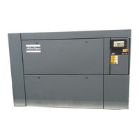
31 pages
GA55 User Manual

36 pages
ga37 User Manual
128 pages
GA 37 VSD Instruction Book
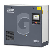
45 pages
GA5 User Manual

76 pages
GX 7 Instruction Book
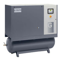
108 pages
GA 15 Instruction Book
70 pages
Air Compressor Instruction Book
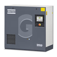
178 pages
GA 5 Instruction Book
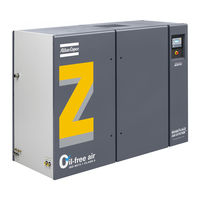
66 pages
ZT Series Instruction Book
45 pages
GA5 User Manual
98 pages
GA 55+ Instruction Book
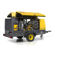
88 pages
XAMS 407 CD Instruction Manual
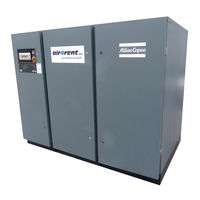
41 pages
GA90 Instruction Book
150 pages
ga55+ Instruction Book
20 pages
GA90 Instruction Book
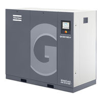
114 pages
GA 75 VSD Instruction Book

138 pages
ZR-55 Instruction Book

138 pages
GA 7 VSD+ Instruction Book

94 pages
GA 18 Instruction Book
Models
Document Type
8
8115410428

Instruction Book
A
Air Compressor
Instruction Book
APF221384
Original Instruction Book
AUTOMAN AC100
Instruction Manual
AUTOMAN AC100E500T
Instruction Manual
AUTOMAN AC100E500TS
Instruction Manual
AUTOMAN AC100T500T
Instruction Manual
AUTOMAN AC100T500TS
Instruction Manual
AUTOMAN AC40
Instruction Manual
AUTOMAN AC40T300T
Instruction Manual
AUTOMAN AC55E300T
Instruction Manual
AUTOMAN AC55E300TS
Instruction Manual
AUTOMAN AC55E500T
Instruction Manual
AUTOMAN AC55E500TS
Instruction Manual
AUTOMAN AC55T500T
Instruction Manual
AUTOMAN AC55T500TS
Instruction Manual
C
CR Series
Instruction Book
CRC10
Instruction Book
CRC15
Instruction Book
CRC20
Instruction Book
CRI10
Instruction Book
CRI15
Instruction Book
CRI5
Instruction Book
CRI7.5
Instruction Book
CRP20
Instruction Book
E
Elektronikon II
User Manual
G
G 15L
Instruction Book
G 160 VSD
Original Instruction Book
G 18
Instruction Book
G 2
Instruction Book
G 22
Instruction Book
G 3
Instruction Book
G 4
Instruction Book
G 5
Instruction Book
G 7
Instruction Book
GA 11 VSD
Instruction Book
GA 11 VSD MED
Instruction Book
GA 11 VSD+
Instruction Book
GA 11+
Instruction Book
GA 110 VSD
Instruction Book
GA 132 VSD
Instruction Book
GA 15 MED
Instruction Book
GA 15 VSD MED
Instruction Book
GA 15 VSD+
Instruction Book
GA 15+
Instruction Book
GA 160 VSD
Instruction Book • Instruction Book
GA 18 MED
Instruction Book
GA 18+
Instruction Book
GA 22 MED
Instruction Book
GA 22+
Instruction Book
GA 26+
Instruction Book
GA 30+
Instruction Book • Instruction Book
GA 37 VSD
Instruction Book
GA 37+
Instruction Book
GA 45 VSD
Instruction Book
GA 45+
Instruction Book
GA 5 MED, GA 7 MED, GA 11 MED
Instruction Book
GA 5 VSD MED
Instruction Book
GA 55+
Instruction Book • Instruction Book
GA 7 VSD MED
Instruction Book
GA 7 VSD+
Instruction Book
GA 75 VSD
Instruction Book
GA 90 VSD
Instruction Book
GA11
User Manual • Instruction Book • User Manual • Instruction Book
GA110
Instruction Book • Instruction Book • Instruction Book
GA110W
Instruction Book • Instruction Book
GA11C
User Manual • User Manual
GA132
Instruction Book • Instruction Book • Instruction Book
GA132W
Instruction Book • Instruction Book
GA15
User Manual • Instruction Book • Instruction Book • User Manual • Instruction Book • Instruction Book
GA160
Instruction Book • Instruction Book • Instruction Book
GA160W
Instruction Book • Instruction Book
GA18
User Manual • Instruction Book • User Manual • Instruction Book • Instruction Book • Instruction Book
GA18 VSD
Instruction Book
GA18WVSD
User Manual
GA200
Instruction Book • Instruction Book • Instruction Book
GA200W
Instruction Book • Instruction Book
GA22
User Manual • Instruction Book • User Manual • Instruction Book • Instruction Book
GA250
Instruction Book • Instruction Book • Instruction Book
GA250W
Instruction Book • Instruction Book
GA30
User Manual • User Manual • Instruction Book
GA30 VSD
Instruction Book
GA30 W-37
User Manual
GA30 W-45
User Manual
GA30 W-55
User Manual
GA30 W-55C
User Manual
GA30 W-75
User Manual
GA30 W-90C W
User Manual
GA30C
User Manual • Instruction Book • User Manual
GA30W
User Manual
GA30WVSD
User Manual
GA315
Instruction Book • Instruction Book • Instruction Book
GA315W
Instruction Book • Instruction Book
GA37
User Manual • User Manual • User Manual • Instruction Book
GA37W
User Manual
GA37WVSD
User Manual
GA45
User Manual • User Manual • Instruction Book
GA45W
User Manual
GA45WVSD
User Manual
GA5
User Manual • User Manual • User Manual • Instruction Book
GA50 (W) VSD
Instruction Book
GA50WVSD
User Manual
GA55
User Manual • User Manual • User Manual
GA55C
User Manual • User Manual
GA55CW
User Manual
GA55W
User Manual
GA55WVSD
User Manual
GA7
User Manual • User Manual • Instruction Book
GA75
User Manual • User Manual
ga75+
Instruction Book
GA75W
User Manual
GA75WVSD
User Manual
GA90
Instruction Book • Instruction Book • Instruction Book • Instruction Book • Instruction Book
GA90 (W) VSD
Instruction Book
GA90C
User Manual • User Manual • User Manual
GA90CW
User Manual
GA90W
Instruction Book • Instruction Book
GA90WVSD
User Manual
GR110
Instruction Book
GR110 W
Instruction Book
GR132
Instruction Book
GR132 W
Instruction Book
GR160
Instruction Book
GR160 W
Instruction Book
GR200
Instruction Book
GR200 W
Instruction Book
GX 11
Instruction Book
GX 2 EP
Instruction Book
GX 3 EP
Instruction Book
GX 4 EP
Instruction Book
GX 5 EP
Instruction Book
GX 7
Instruction Book
GX 7 EP
Instruction Book
L
LE10
Instruction Book
LE11
Instruction Book
LE110
Instruction Book
LE12
Instruction Book
LE15
Instruction Book • Instruction Book
LE150
Instruction Book
LE2
Instruction Book
LE20
Instruction Book
LE22
Instruction Book
LE3
Instruction Book
LE40
Instruction Book
LE5
Instruction Book • Instruction Book
LE55
Instruction Book
LE6
Instruction Book
LE7
Instruction Book • Instruction Book
LE75
Instruction Book
LE7N
Instruction Book
LE8
Instruction Book
LE9
Instruction Book
LE9N
Instruction Book
LF 10
Instruction Book • Instruction Book
LF 2
Instruction Book • Instruction Book
LF 3
Instruction Book • Instruction Book
LF 5
Instruction Book • Instruction Book
LF 7
Instruction Book • Instruction Book
LF15
Instruction Book
LF22
Instruction Book
LF40
Instruction Book
LF55
Instruction Book
LF75
Instruction Book
LFx 0.7
Instruction Book
LFx 1.0
Instruction Book
LFx 1.5
Instruction Book
LFx 2.0
Instruction Book
LFx D 0.7
Instruction Book
LFx D 1.0
Instruction Book
LFx D 1.5
Instruction Book
LFx D 2.0
Instruction Book
LT10
Instruction Book
LT11
Instruction Book
LT110
Instruction Book
LT12
Instruction Book
LT1230
Instruction Book
LT15
Instruction Book • Instruction Book
LT15/30
Instruction Book
LT15/60
Instruction Book
LT150
Instruction Book
LT2
Instruction Book
LT20
Instruction Book
LT20/30
Instruction Book
LT22
Instruction Book
LT3
Instruction Book
LT40
Instruction Book
LT5
Instruction Book • Instruction Book
LT530
Instruction Book
LT55
Instruction Book
LT6
Instruction Book
LT7
Instruction Book • Instruction Book
LT730
Instruction Book
LT75
Instruction Book
LT8
Instruction Book
LT9
Instruction Book
LT930
Instruction Book
M
MAS 200
Instruction Book
O
ORV 10
Instruction Manual
ORV 12
Instruction Manual
ORX 10
Instruction Manual
ORX 12
Instruction Manual
P
PNS 1250 Cud S3A/T3 APP
Instruction Manual
PTS 1600 Cud S3A/T3 APP
Instruction Manual
PTS 916 Cd
Instruction Manual
S
SF 1
Instruction Book
SF 15+
Instruction Book
SF 17+
Instruction Book
SF 2
Instruction Book
SF 22+
Instruction Book
SF 4
Instruction Book
SF1 Skid
Instruction Book
SF15 Multi
Instruction Book
SF2 Skid
Instruction Book
SF4 Skid
Instruction Book
SF6 Multi
Instruction Book • Instruction Book
SF8 Multi
Instruction Book
SFD 11+
Instruction Book
SFD 15+
Instruction Book
SFD 22+
Instruction Book
SK 160 SA 1
Instruction Manual
U
U190 PACE KD WUX
Installation Manual
W
W-37
User Manual • User Manual
W-45
User Manual • User Manual
W-55
User Manual • User Manual
W-55C
User Manual • User Manual
W-75
User Manual • User Manual
W-90C
User Manual
W-90C W
User Manual
X
XA 375 DD6
Instruction Manual
XA(S) 137 DD
Instruction Manual
XA(S) 137 DDG
Instruction Manual
XA(S) 186 Dd
Instruction Manual • Instruction Manual
XA(S) 300 DD7
Instruction Manual
XA(S) 300 DD7G
Instruction Manual
XA146 Dd
Instruction Manual
XA186 Dd
Instruction Manual • Instruction Manual
XAHS 107 DD
Instruction Manual
XAHS 146 Dd
Instruction Manual • Instruction Manual
XAHS 186 Cud PNE
Instruction Manual
XAHS 186 Dd
Instruction Manual • Instruction Manual
XAHS 250 DD7
Instruction Manual
XAHS 300 DD6
Instruction Manual
XAHS 347 CD
Instruction Manual
XAHS 37 DD
Instruction Manual
XAHS 375 DD6
Instruction Manual
XAHS 38 Kd
Instruction Manual
XAHS 426
Instruction Manual
XAHS 447
Instruction Manual
XAHS 447 Cd S3A APP
Instruction Manual
XAHS 70 DD7
Instruction Manual
XAHS 710 CD7
Instruction Manual
XAHS 900 CD6 XAVS 396
Instruction Manual
XAHS 950 Cd7
Instruction Manual
XAHS 950 CD7 T3 APP
Instruction Manual
XAHS106 Dd
Instruction Manual
XAHS146 Dd
Instruction Manual
XAHS186 Dd
Parts List
XAHS365 Md
Instruction Manual
XAMS 1050 CD6 XATS 456
Instruction Manual
XAMS 1150 Cd7
Instruction Manual
XAMS 1150 CD7 T3 APP
Instruction Manual
XAMS 407 CD
Instruction Manual
XAMS 496
Instruction Manual
XAMS 527
Instruction Manual
XAMS 527 Cd S3A APP
Instruction Manual
XAMS 850 CD7
Instruction Manual
XAMS286 Md
Parts List
XAS 110 DD7
Instruction Manual
XAS 130 DD7 C3 APP
Instruction Manual
XAS 150 DD7 C3 APP
Instruction Manual
XAS 175 Dd
Instruction Manual
XAS 185 CD7 T4
Instruction Manual
XAS 185 CD7 T4F HOP
Instruction Manual
XAS 185 CDU T4
Original Instructions Manual
XAS 185 DD7 C3 APP
Instruction Manual
XAS 185 KD7 IT4
Instruction Manual
XAS 185 KD7 T4
Instruction Manual
XAS 185 KDU T4F HOP
Instruction Manual
XAS 375 DD6
Instruction Manual
XAS 400 JD IT4 HOP
Instruction Manual
XAS 47 DD
Instruction Manual
XAS 48 G Kd
Instruction Manual
XAS 57 DD
Instruction Manual
XAS 58 Kd
Instruction Manual
XAS 67 Dd C3 APP
Instruction Manual
XAS 68 G Kd
Instruction Manual
XAS 68 Kd
Instruction Manual
XAS 77 Dd C3 APP
Instruction Manual
XAS 78 Kd
Instruction Manual
XAS 88 Kd
Instruction Manual
XAS 90 DD7
Instruction Manual
XAS 97 Dd C3 APP
Instruction Manual
XAS146 Dd
Instruction Manual
XAS186 Dd
Instruction Manual
XAS96JD
Instruction Book
XASE1600 Gd
Instruction Manual
XATS 1050 Cd7
Instruction Manual
XATS 1050 CD7 T3 APP
Instruction Manual
XATS 125 DD7 C3 APP
Instruction Manual
XATS 156 Dd
Instruction Manual • Instruction Manual
XATS 350 DD6
Instruction Manual
XATS 377 CD
Instruction Manual
XATS 487
Instruction Manual
XATS 487 Cd S3A APP
Instruction Manual
XATS 68 Kd
Instruction Manual
XATS 800 CD7
Instruction Manual
XATS 950 CD6
Instruction Manual
XATS156 Dd
Instruction Manual
XAVS 166 Dd
Instruction Manual • Instruction Manual
XAVS 307 CD
Instruction Manual
XAVS 340 DD6
Instruction Manual
XAVS 407
Instruction Manual
XAVS 407 Cd S3A APP
Instruction Manual
XAVS 650 CD7
Instruction Manual
XAVS 830 CD6
Instruction Manual
XAVS 900 Cd7
Instruction Manual
XAVS 900 CD7 T3 APP
Instruction Manual
XAVS136 Dd
Instruction Manual
XRHS 1100 CD6
Instruction Manual • Instruction Manual
XRHS 1150 CD4 C3 WUX
Instruction Manual
XRHS 506
Instruction Manual
XRHS 506 Cd
Instruction Manual
XRHS 506 Cd C13
Instruction Manual
XRHS 527 Cd C3 WUX
Instruction Manual
XRHS385 Md
Instruction Manual
XRHS396

(Danish) Betjeningsvejledning
XRVS 1000 CD6
Instruction Manual • Instruction Manual
XRVS 1000 CD8 T4F HOP
Instruction Manual
XRVS 1050 CD4 C3 WUX
Instruction Manual
XRVS 1300 CD7
Instruction Manual
XRVS 1350
Instruction Manual
XRVS 1350 CD7
Instruction Manual
XRVS 476
Instruction Manual
XRVS 476 Cd
Instruction Manual
XRVS 476 Cd C13
Instruction Manual
XRVS 487 Cd C3 WUX
Instruction Manual
XRVS 617 Cd
Instruction Manual
XRVS 647
Instruction Manual
XRVS 647 Cd
Instruction Manual
XRVS455 Md
Instruction Manual
XRXS 1240 CD7
Instruction Manual
XRXS 1275
Instruction Manual
XRXS 1275 CD7
Instruction Manual
XRXS 567 Cd
Instruction Manual
XRXS 607
Instruction Manual
XRXS 607 Cd
Instruction Manual
XRYS 126
Instruction Manual
XRYS 577
Instruction Manual
Z
ZR 110
Instruction Book
ZR 132
Instruction Book
ZR 145
Instruction Book
ZR 160
Instruction Book
ZR 200
Instruction Book • Instruction Book
ZR 250
Instruction Book
ZR 275
Instruction Book
ZR Series
Instruction Book
ZR-55
Instruction Book
ZR-75
Instruction Book
ZR-90
Instruction Book
ZR30
Instruction Book
ZR37
Instruction Book
ZR45
Instruction Book
ZR55-ZR75-ZR90
Instruction Book
ZT 110
Instruction Book
ZT 132
Instruction Book
ZT 145
Instruction Book
ZT 160
Instruction Book
ZT 200
Instruction Book
ZT 250
Instruction Book
ZT 275
Instruction Book
ZT Series
Instruction Book
ZT-55
Instruction Book • Instruction Book
ZT-75
Instruction Book
ZT-90
Instruction Book
ZT15
Instruction Book
ZT18
Instruction Book
ZT22
Instruction Book
ZT30
Instruction Book
ZT37
Instruction Book
ZT45
Instruction Book
ZT55-ZT75-ZT90
Instruction Book
Основные характеристики
| Страна | Швеция |
| Производитель | Atlas Copco |
| Вид компрессора | Винтовой |
| Производительность | 1300 л/мин (1.3 м3/мин) |
| Рабочее давление | 7.5 атм |
| Мощность двигателя | 7 кВт |
| Питание | 380 В |
| Тип привода | Ременной |
| Тип двигателя | Электрический |
| Трехфазный | Да |
| Малошумный | Нет |
| Спиральный | Нет |
| Уровень шума | 61 дБ |
| Безмасляный | Нет |
| На шасси | Нет |
Габариты
| Габаритные размеры (длина) | 1245 мм |
| Габаритные размеры (ширина) | 710 мм |
| Габаритные размеры (высота) | 1240 мм |
| Масса | 315 кг |
Дополнительная информация
| Объём ресивера | Без ресивера |
| Частотный привод | Нет |
| С осушителем | Да |
| Емкость масляной системы компрессора | 3.7 л. |
| Число оборотов максимум | 2940 об/мин |
| Тип охлаждения | Воздушное |
| Температура сжатого воздуха на выходе | 28 |
| Выходной разъём | 3/4 дюйма |
| Манометр | Да |
| Максимальная наружная температура | 46 °С |
Винтовой компрессор Atlas Copco GA 7 7,5 FF производительностью 1300 л/мин, рабочим давлением в 7.5 атм и мощностью в 7 кВт. Работает от сети напряжением в 380 В. Оснащён осушителем. Тип привода – Ременной.
Компрессоры Атлас Копко серии GA отвечают самым жестким требованиям, предъявляемым промышленностью. Высокая надежность, малые размеры, чрезвычайно низкий уровень шума, встраиваемое оборудование для подготовки воздуха и очистки конденсата – все это позволяет компрессорам серии GA находиться вблизи точки потребления воздуха. Данное обстоятельство позволяет отказаться от централизованной компрессорной и дорогостоящих пневмомагистралей с огромной протяженностью. Отсутствие вибраций и совершенство конструкции позволяет ставить компрессоры Атлас Копко на ровный пол (специальный фундамент не требуется).
Оборудован русифицированым микропроцессорным модулем Elektronikon®Mk5 и встроенным в корпус рефрижераторным осушителем сжатого воздуха, обеспечивающим на выходе сухой сжатый воздух с температурой точки росы +3°С. Такая компоновка «все в одном» снижаем потребность в площади при установке компрессора, обеспечивает единую точку подвода электроэнергии, компрессорная система приходит в собранном и протестированном виде. предусмотрены ручная и автоматическая система дренажа конденсата.
Режим работы: нагрузка, холостой ход (разгрузка), временное отключение.
Особенности и преимущества
- Оптимизированный ременный привод — непревзойденная надежность на протяжении всего жизненного цикла благодаря технологичному ременному приводу, разработанному в соответствии с высочайшими промышленными стандартами.
- Проверенный временем винтовой элемент — компрессорный узел GA 5-11’s в комбинации с электродвигателем соответствующему стандарту IE3, улучшенным подшипникам и уплотнениям минимизирует расходы на эксплуатацию, сохраняет работоспособность при повышенной температуре воздуха в рабочем помещении (вплоть до 46°C), параметр FAD (Free Air Delivery) улучшен на 8%, а потребление электроэнергии уменьшено на 7%.
- Встроенный осушитель сжатого воздуха позволяет избежать как конденсации влаги, так и коррозии элементов пневмосистемы, дополнительная экономия электроэнергии за счет применения электронного клапана сброса конденсата без потери давления сжатого воздуха.
- Контроллер Elektronikon — индикация состояния и управление компрессором Elektronikon® нового поколения для удаленного контроля с использованием стандартного интернет-соединения, обеспечивает контроль всех необходимых рабочих параметров и состояния компрессора.
- Высокотехнологичный масляный сепаратор — защита от загрязнения маслом: крайне низкий уровень выноса масла благодаря вертикальному дизайну бака сепаратора.
- Несложные установка и обслуживание — plug-and-play готовое к быстрой установке вблизи точки потребления сжатого воздуха.
Опции
| Фильтр DD (Только для FF) | 24168 р. |
| Фильтр UD (Только для FF) | 49704 р. |
| Байпасный канал осушителя (только для FF) | 46056 р. |
| Фильтр DD + байпас осушителя (только для FF) | 75240 р. |
| Фильтр UD + байпас осушителя (только для FF) | 104880 р. |
| Ресивер увеличенного объема (500л) | 25992 р. |
| EWD для компрессора версии Pack | 36480 р. |
| EWD для ресивера | 35568 р. |
| Замена Электроникона «Стандарт» на «График» | 13680 р. |
| Высокотемпературная версия для PACK | 24624 р. |
| Высокотемпературная версия для FF | 24624 р. |
| Антиобледенительная система (до -10С) | 115368 р. |
| Тропический термостат | 456 р. |
| Защита от дождя | 39216 р. |
| Усиленный воздушный (впускной) фильтр | 58824 р. |
| Префильтр | 77064 р. |
|
Термисторы и антиконденсационный подогрев двигателя |
20064 р. |
| Реле последовательности фаз | 23256 р. |
| RXD oil | 3192 р. |
| Лицензия ES4i | 36024 р. |
| Лицензия ES6i | 90288 р. |
| Производительность: | 1150 л/мин |
| Рабочее давление: | 7 атм |
| Мощность двигателя: | 7.5 кВт |
| Объём ресивера: | Без ресивера |
| Производительность: | 1200 л/мин |
| Рабочее давление: | 7.5 атм |
| Мощность двигателя: | 7.5 кВт |
| Объём ресивера: | Без ресивера |
| Производительность: | 1200 л/мин |
| Рабочее давление: | 8 атм |
| Мощность двигателя: | 45 кВт |
| Объём ресивера: | Без ресивера |
| Производительность: | 1260 л/мин |
| Рабочее давление: | 7.5 атм |
| Мощность двигателя: | 30 кВт |
| Объём ресивера: | Без ресивера |
| Производительность: | 1480 л/мин |
| Рабочее давление: | 10 атм |
| Мощность двигателя: | 45 кВт |
| Объём ресивера: | Без ресивера |
| Производительность: | 1450 л/мин |
| Рабочее давление: | 4 атм |
| Мощность двигателя: | 30 кВт |
| Объём ресивера: | Без ресивера |
| Производительность: | 1260 л/мин |
| Рабочее давление: | 10 атм |
| Мощность двигателя: | 9 кВт |
| Объём ресивера: | Без ресивера |
| Производительность: | 1430 л/мин |
| Рабочее давление: | 10 атм |
| Мощность двигателя: | 11 кВт |
| Объём ресивера: | Без ресивера |
| Производительность: | 1400 л/мин |
| Рабочее давление: | 10 атм |
| Мощность двигателя: | 11 кВт |
| Объём ресивера: | Без ресивера |
| Производительность: | 1300 л/мин |
| Рабочее давление: | 7.5 атм |
| Мощность двигателя: | 7 кВт |
| Объём ресивера: | 270 л. |
| Производительность: | 1300 л/мин |
| Рабочее давление: | 7.5 атм |
| Мощность двигателя: | 7 кВт |
| Объём ресивера: | Без ресивера |
| Производительность: | 1300 л/мин |
| Рабочее давление: | 7.5 атм |
| Мощность двигателя: | 7 кВт |
| Объём ресивера: | 270 л. |
Меры безопасности при эксплуатации
1. Запрещается касаться трубопроводов и других элементов машины во время ее работы.
2. Используйте только правильные типы и размеры концевых фитингов шлангов и соединений. При продувке воздуха через шланг или трубопровод надежно закрепите свободный конец. Незакрепленный конец шланга под давлением может вырваться, причинив травму. Перед тем, как отсоединять шланг, убедитесь, что давление в нем сброшено.
3. В качестве дополнительной меры безопасности оператор, отключающий машины с дистанционным управлением, должен принять соответствующие меры, чтобы убедиться, что их никто не будет осматривать или использовать. С этой целью оборудование с дистанционным управлением необходимо снабдить соответствующими предупреждающими табличками.
4. Никогда не работайте с оборудованием, если существует возможность возгорания или появления токсичного дыма, испарений или частиц.
5. Никогда не нагружайте оборудование ниже или выше его номинальных характеристик.
6. Во время работы держите все дверцы конструкции закрытыми. Разрешается открывать дверцы на короткое время, например, для текущих проверок. Вставляйте в уши беруши, когда открываете дверцы.
При работе вблизи машин, не оснащенных корпусом, необходимо использовать средства защиты органов слуха.
7. Работники, находящиеся в помещениях, где уровень звукового давления достигает или превышает 80 дБ(A), должны пользоваться противошумными наушниками.
8. Периодически проверяйте, что:
• Все защитные щитки находятся на своих местах и надежно закреплены
• Все шланги и/или трубки внутри машины находятся в хорошем и надежном состоянии и не истираются
• Отсутствие утечек
• Плотность затяжки всех крепежных элементов
• Все электрические проводники закреплены и находятся в хорошем состоянии
• Предохранительные клапаны и другие устройства для сброса давления не забиты грязью или краской
• Выходной клапан воздуха и воздушная сеть, т.е. трубы, муфты, коллекторы, клапаны, шланги и т.д., находятся в хорошем состоянии, не изношены и правильно эксплуатируются
• Воздушные фильтры охлаждения электрического шкафа не засорены
9. В том случае, если теплый охлаждающий воздух, выходящий из компрессора, используется в воздушно-отопительных системах (например, для отопления рабочих цехов), необходимо принять соответствующие меры предосторожности против загрязнения воздуха или возможного отравления атмосферы.
10. На компрессорах с водяным охлаждением, использующих колонны охлаждения с открытым контуром, необходимо принять защитные меры для предотвращения размножения вредных бактерий, таких как Legionella pneumophila.
11. Не удаляйте и не разрушайте звукоизолирующие материалы.
12. Никогда не демонтируйте и не выводите из строя приборы безопасности, щитки или изоляцию, установленные в машине. Каждый сосуд или вспомогательное устройство для сбора воздуха, установленное снаружи машины и находящееся под давлением, величина которого выше атмосферного, должен быть защищен прибором или приборами для сброса давления, согласно требованиям.
13. Воздушный ресивер следует проверять ежегодно. Должна соблюдаться минимальная толщина стенки, указанная в инструкции по эксплуатации. Требования местных норм применяются, если они более строгие.
![]() Скачать полную инструкцию компрессора Atlas Copco GA 75 VSD
Скачать полную инструкцию компрессора Atlas Copco GA 75 VSD
![]() Регламенты технического обслуживания Atlas Copco
Регламенты технического обслуживания Atlas Copco
Инструкция по эксплуатации для компрессора atlas ga7ff
Винтовой компрессор Atlas Copco GA 7 — 7.5


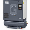


GA 7 – это винтовые компрессоры с воздушным охлаждением. Комплектуются всеми необходимыми патрубками и трубопроводами, автоматической системой слива конденсата, крепятся на собственной силовой раме.
Компрессор состоит из компрессорного элемента, электродвигателя, который полностью закрыт и принудительно охлаждается системой охлаждения, а также систем регулирования и контроля. Специальный звукоизолирующий корпус полностью закрывает компрессор, а также смонтированный внутри шкаф электроавтоматики с микропроцессорным модулем Elektronikon. В качестве опции возможна установка рефрижераторного осушителя, магистральных фильтров, а также установка компрессора на ресивер.
Версия FF: встроенный осушитель воздуха
Оборудован русифицированным микропроцессорным модулем Elictronikon Mk5 и встроенным в корпус рефрижераторным осушителем сжатого воздуха, обеспечивающий на выходе сухой сжатый воздух с температурой точкой росы +3°C. Такая компоновка «все в одном» снижаем потребность в площади при установке компрессора,обеспечивает единую точку подвода электроэнергии, компрессорная система приходит в собранном и протестированном виде. предусмотрены ручная и автоматическая система дренажа конденсата. Режим работы: нагрузка, холостой ход (разгрузка), временное отключение.
Версия PACK: без осушителя воздуха
Оборудован русифицированным микропроцессорным модулем Elictronikon Mk5. Рекомендуется для применения в производствах, где точка росы либо не регламентирована, либо где требования по точке росы значительно превосходят значение +3°C (в этом случае применяется совместно с осушителем адсорбционного и мембранного типа). Режим работы: нагрузка, холостой ход (разгрузка), временное отключение.
ОСОБЕННОСТИ И ПРЕИМУЩЕСТВА ВИНТОВЫХ КОМПРЕССОРОВ ATLAS COPCO GA 5-11
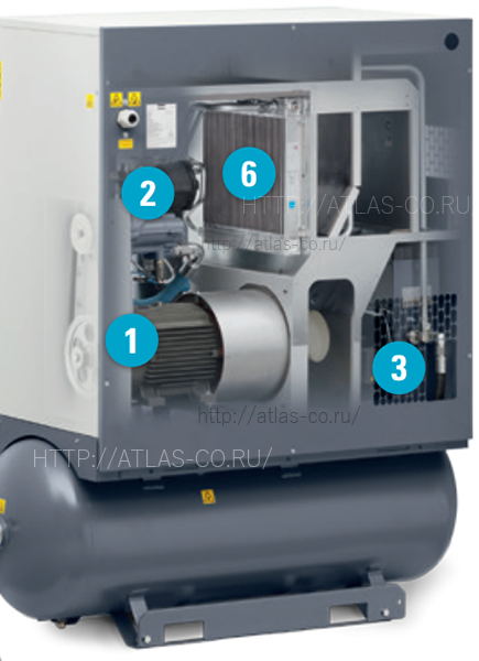
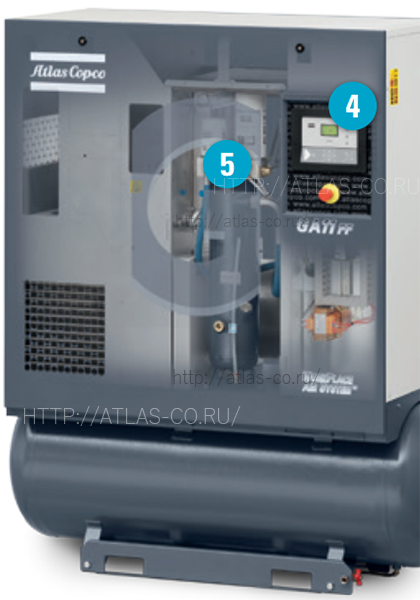
1 — Оптимизированный ременный привод:
Непревзойденная надежность на протяжении всего жизненного цикла благодаря технологичному ременному приводу, разработанному в соответствии с высочайшими промышленными стандартами.
2 — Проверенный временем винтовой элемент:
- Компрессорный узел GA 5-11’s в комбинации с электродвигателем соответствующему стандарту IE3, улучшенным подшипникам и уплотнениям минимизирует расходы на эксплуатацию.
- Сохраняет работоспособность при повышенной температуре воздуха в рабочем помещении (вплоть до 46°C) благодаря совершенному дизайну и расположению компонентов.
- Параметр FAD (Free Air Delivery) улучшен на 8%, а потребление электроэнергии уменьшено на 7% благодаря оптимизированному расположению элементов и совершенному компрессорному элементу.
3 — Встроенные очистка и осушка сжатого воздуха
- Защита потребляющего сжатый воздух оборудования во всех ситуациях: встроенный осушитель сжатого воздуха позволяет избежать как конденсации влаги, так и коррозии элементов пневмосистемы
- Дополнительная экономия электроэнергии за счет применения электронного клапана сброса конденсата без потери давления сжатого воздуха.
- Опциональные фильтры сжатого воздуха могут быть использованы для достижения качества сжатого воздуха, соответствующему 1 классу (фильтрация загрязнений Привод. Система охлаждения компрессора. Система смазки. Воздушная система. Шкаф управления. Система регулировки производительности. Модуль управления Elektronikon.
Самые злободневные вопросы по Atlas Copco и ответы на них
Мусор в компрессоре.
Да! Не пыль и даже не крупные частицы!
Бывают случаи выхода из строя компрессоров, по причине попадания в них крупного мусора, камней, щебня, палок.
Попадают в вентиляторы, крыльчатки, ремни, что снижает ресурс или может приводить к поломкам.
Внимание!
В инструкции по эксплуатации даны рекомендации по установке компрессора.
Помещение должно быть чистым. При заборе воздуха с улицы, где может присутствовать пух, листья, насекомые и т.д., рекомендуем
установить предварительный фильтр от пыли, листвы на приточную вентиляцию.
Если компрессор стоит в грязном помещении или цеху, то можно предварительный фильтр поставить на него, а на выброс сделать отвод воздуха,
чтобы исключить поппадание камней во внутрь оборудования.
От всех негативных факторов не убережешь оборудование, но можно их минимизировать и продлить срок службы оборудования.


Новый улучшенный контроллер Elektronikon MK5 Touch
Повилась новая модель блока управления винтовыми компрессорами Атлас Копко.
Сенсорный экран высокого разрешения (можно интуитивно нажимать на экран и устанавливать параметры)
Артикул: 1900520400 Elektronikon MK5 Touch
• Оптимизация энергоэффективности
• Встроенное подключение через SMARTLINK 2.0
• Повышенная защита машины
• Полная автоматизация
• Простая в использовании панель навигации со светодиодными значками


Основные рекомендации описаны в инструкции и частично продублированы в комиксе:
1. Компрессор устанавливаем на ровный пол
2. Оставляем пространство вокруг компрессора для проведения технического обслуживания
3. Поверхность должна быть ровной
4. Перед включением необходимо демонтировать транспортировочный крепеж
5. Должна быть защита кабеля
6. Ввод кабеля осуществить через гермоввод
7. Необходимо проконтролировать направления вращения электродвигателя и вентиляторов охлаждения
8. При сбросе конденсата, необходим разрыв
9. Правильная вентиляция небольших помещений, чтобы исключить перегрев
10. Если есть поплавковые конденсатоотводчики на фильтрах и присутствуют автоматические, требуется обеспечить сброс в магистраль без передавливания по давлению
11. Внимание! Часто встречается данная ошибка.
Необходимо подключаться в магистраль через колено, чтобы возможный конденсат со всего завода не устремлялся к компрессору.
Мы даем рекомендации перед поставкой оборудования, во время пусконаладочных работ и в процессе эксплуатации, чтобы Вам было комфортно работать и оборудование служило дольше.

Если происходит утечка компрессорного масла по валу винтового блока, то необходимо произвести замену уплотнения винтового блока (сальник).

1630218188 Втулка одевается на вал винтового блока. На валу винтового блока есть паз для уплотнительного кольца. Если данный паз отсутствует, то необходимо втулку посадить на вал используя Loctite 641.

 На адсорбционных осушителях горячей регенерации термоизоляция является опцией для стандартных BD+ с точкой росы PDP -40C, для BD+ с точкой росы PDP -70C термоизоляция поставляется в составе опции -70С.
Термоизоляция повышает энергоэффективность системы и позволяет тем самым достигать более высокий уровень осушения сжатого воздуха.

На фотографии изображен корпус магистрального фильтра сжатого воздуха Атлас Копко, на котором написан артикул элемента, требующего замены.
Если изображения нет, то данный артикул дублируется на самом элементе фильтра. Если фильтр встроен в компрессорную установку, то по его серийному номеру на шильде можно запросить деталировку и посмотреть в ней, чтобы избежать ошибки
 Во многих наборах лежит невзрачный фильтр электрошкафа. Фильтровальный материал похож на синтипон, но это не он. Если данный фильтр не менять, то в какой то момент начнет нарушаться вентиляция в электрошкафу, что снизит работу электрических модулей. Проникающие твердые частицы тоже не пойдет на пользу автоматам, контакторам и тиристорам в частотных преобразователях.
Меняйте данные фильтры по мере загрязнения!
Аварийная кнопка нужна для аварийного выключения!
На фотографии аварийная кнопка, которой на протяжении длительного времени выключали компрессор. Она расшаталась, перекрутилась и оборвался провод. Компрессор Атлас Копко перестал включаться. При таких нажатиях компрессорное оборудование может выйти из строя из-за не выполненной разгрузки перед выключением.

 Это очень редкий случай на данных компрессорных установках.
В воздушном фильтре масло может быть по нескольким причинам.
Основные:
1) Забилась линия эвакуации масла с сепаратора или неисправен обратный клапан линии эвакуации масла.
Сепаратор переполняется маслом и в воздушную линию управления впускным клапаном попадает масло.
2)Неисправен клапан минимального давления и обратный клапан самого компрессора.
При выключении происходит обратное вращение или гидроудар, масло выбрасывается при разгрузке и попадает на воздушный фильтр.
Размышление является личным мнением автора и носит исключительно информационный характер.
Технологию применения спиральных блоков часто можно было увидеть в Японии в холодильных компрессорах, которые рассчитаны на работу исключительно в режиме периодической нагрузки.
Конструкция такого узла достаточно сложная и дорогая. Этот блок не может быть переделан или капитально отремонтирован, поэтому меняется целиком. Из-за короткого срока службы подшипников, срок службы спирального блока составляет всего 10 000 часов (бывает незначительно больше или меньше в зависимости от давления и условий эксплуатации).
Спиральный блок не позволяет достигать высокой производительности, поэтому он используется в небольших компрессорах мощностью от 1,5 до 15 кВт.
В самой большой модели SF15 устанавливается сразу четыре спиральных блока и четыре электромотора, что увеличивает стоимость капремонта, обслуживания и стоимость самого компрессора.
Чтобы производительность блока не падала в ходе эксплуатации из-за растущих зазоров между корпусом и спиралью, антифрикционные уплотнения для увеличения эффективности нужно своевременно менять. Чтобы снизить потери производительности, необходимо фильтровать всасываемый воздух. Установленные на входе воздушные фильтры отсеивают твердые частицы и замедляют износ уплотнений.
 Atlas Copco является гарантом получения качественного изделия Заказчиком. OEM завод изготовитель не продает запасные части, которые делает для Atlas Copco.
Аналоги встречаются по размерам у многих заводов, но каждый раз можно получить разное качество (отсутствует контроль), что затрудняет прогнозирование проведения технического обслуживания.
Это является конфиденциальной информацией (производители могут меняться, но могут изготавливаться и на собственных заводах)
https://www.atlascopcogroup.com/en/about-us/brands
В некоторых винтовых компрессорных установках Атлас Копко на всасывающей линии есть индикатор загрязненности воздушного фильтра.
Если красная часть сервис-индикатора воздушного фильтра показывает полную выработку ресурса фильтра, замените элемент воздушного фильтра. Сбросьте сервис-индикатор, нажав на кнопку, расположенную на краю корпуса, а также переустановите настройки предупреждения о необходимости технического обслуживания.


 Охлаждение винтового компрессора осуществляется или крыльчаткой основного электродвигателя или дополнительным электродвигателем с вентилятором, который устанавливается на радиатор.
Вентилятор охлаждения может располагаться вертикально или горизонтально. При перепадах температуры в цехах (охлаждение металлических поверхностей) на них из горячего воздуха выпадает конденсат. На этот конденсат садится пыль цементная, сахарная, земляная и т.д.
При правильном монтаже вентиляции данная ситуация не актуальна. Фильтрация воздуха охлаждения происходит на линиях приточного воздуха к компрессору или на приточном воздухе общеобменной вентиляции. Пыль не должна попадать с улицы сразу в компрессор.
Загрязнение лопостей крыльчатки охлаждения компрессора (неравномерного налипание грязи) — происходит дисбаланс и разрушение подшипников или посадочного места у электродвигателя охлаждения.
Обратите внимание на крыльчатку вентилятора охлаждения и если она грязная — проводите очистку, внесите данную процедуру в регламент ежедневного, еженедельного, ежемесячного обслуживания.
В компрессорных установках Атлас Копко электросхема расположена в электрическом отсеке.

На безмаслянных компрессорных установках SF есть подшипники, которые необходимо смазывать.
Есть регламент, который не рекомендуется нарушать. Необходимо по мере загрязнения производить замену воздушного фильтра и тогда компрессорная установка будет хорошо работать.


Необходимо по рекомендованному заводом изготовителем регламенту проводить техническое обслуживание винтового компрессора, чтобы все работало исправно.
Произвели замену фильтров, заменили масло и перебрали клапаны.
При эксплуатации оборудования без замены расходных материалов — увеличиваются риски выхода оборудования из строя.

 Если при смене масляного фильтра или сепаратора, Вы видите элементы коррозии или эмульсию (воду в масле), то необходимо полностью сменить масло в системе и заменить расходные материалы.
Какие причины коррозии в винтовом компрессоре?
Основная причина появления коррозии — это вода.
В воздухе содержится вода, которая частично при сжатии внутри компрессора остается в масле.
Если масло разогрето, то вода уходит вместе с воздухом в трубопровод и на пневмооборудование.
После компрессора ставят осушители, которые воду из воздуха убирают.
Если масло не успевает прогреваться, а компрессор включается кратковременно, то внутри масляной системы накапливается вода. Уровень масла начинает расти. (Если открыть после простоя оборудования сливное отверстие, то пойдет или вода или оранжевая эмульсия).
В современных машинах блоки управления отслеживают такую работу и увеличивают время холостого хода, чтобы система успевала прогреваться. В моделях прошлых поколений необходимо давать машине прогреться.
Это можно сделать, сбросив кратковременно воздух в атмосферу или настроив холостой ход на больший интервал времени.
- Не правильно подобранное оборудование. В таком случае ставят (или надо было ставить) компрессор меньше по производительности, а ресиверов ставят больше.
- Снижение потребления. Меняется расход воздуха на предприятии по причине снижения производства или переходе на другую технологию. Компрессор становится переразмерянным.
- Используются не оригинальные запасные части и масла, бывают реакции, не стабильная работа.
Фильтр воздушный для тяжелых условий эксплуатации Атлас Копко можно встретить в винтовых компрессорных установках серии GA.
Как видно на фотографии — условия эксплуатации достаточно тяжелые.
Установлены на компрессорных установках GA7 GA15, которые применяются в строительной отрасли.
Сжатый воздух идет на производство тратуарной плитки и небольших изделий ландшафтного дизайна.
Компрессорным установкам Атлас Копко 12 лет. Желательно делать общеобменную вентиляцию с предварительной фильтрацией, но не всегда это получается.

 Если у Вас греется винтовой компрессор GA55 Атлас Копко (или подобный), а вентиляция выглядит, как на фотографии, то Вы открываете боковые панели и компрессор начинает работать.
Почему компрессор работает с открытыми дверцами (панелями)?
Перегрев компрессора из-за неправильной вентиляции.
Основные причины:
1) забит пылью или мусором (пухом, насекомыми) радиатор. Его надо продуть в обратную сторону, пропылесосить.
Радиатор должен пропускать свет, а не просто его щёткой отряхнуть.
2 )проверить есть ли теплосъем на входе и выходе из радиатора — разница должны быть около 10 градусов. Это делается или тепловизором или ИК термометром. Руками можно получить ожог. Будьте аккуратны!
Если радиатор холодный, а компрессор перегревается, то проблема в термостатическом клапане.
Термостатический клапан не переключил масло на большой круг через радиатор и произошел перегрев.
3) неправильная вентиляция компрессора, когда она заужена или большой протяженностью, что создает высокое сопротивление воздуха, тепловые пробки и т.д.
Система охлаждения не может обеспечить теплообмен и происходит перегрев винтового компрессора.
Всплывает авария. Открытые дверцы дают временный эффект, но это создает дополнительный шум и загрязнение всего оборудования внутри.
В винтовом компрессоре GA18FF Atlas Copco есть клапан термостатический.
Расзмещается он в гидроплите. Месторасположение выделено красным кругом.
Купить термостат (термостатический клапан) Атлас Копко можно в составе набора или отдельно.
Уточняйте комплектацию.

Так как Атлас Копко ведущий производитель винтовых компрессорных установок, то не обошло стороной и разделение внутри компрессора на горячую и холодную зону.
В холодной зоне организован забор воздуха на сжатие, потому что холодный воздух сжимается лучше горячего и это дает дополнительную энергоэффективность системы в целом.

В Атлас Копко Россия есть центральный склад в г. Химки.
Есть склад нового оборудования, большой склад запасных частей, сервисная служба.
Склады поменьше есть у дилеров в регионах.
Если чего то не нашлось на этих складах, то в течении нескольких недель после Заказа продукция может быть доставлена из Бельгии.
Чтобы избежать простоев оборудования, необходимо проводить плановые работы по обслуживанию винтовых компрессорных установок.
Дополнительно можно приобрести на склад расходные материалы, которые потребуются на следующем обслуживании оборудования.

Если у Вас винтовой компрессор GX или подобный со смотровым глазком, а инструкции по эксплуатации нет или она была потеряна, то необходимо произвести залитие масла, чтобы сверху была «булька» воздуха. Это не каша, много масла — это плохо. Может быть гидроудар.

Для начала необходимо изучить инструкцию по эксплуатации, а затем внутри компрессорной установки найти прессостат (реле давления), открутить верхнюю крышку и отрегулировать верхний порог.
Дельту между верхним и нижним порогом не рекомендуем менять (чтобы небыло постоянных включений и выключений).
Сильно опускать верхний порог тоже не рекомендуется, чтобы не нарушить циркуляцию масла для первоначального запуска системы.
Лучше обратиться в сервисную службу Атлас Копко.

 Как понять, что воздушный фильтр винтового компрессора Атлас Копко пора менять?
1) Посмотреть регламент в инструкции по эксплуатации
2) Раз в год или при наработке 4000
3) Позвонить в сервисную службу Атлас Копко и спросить
Менять чаще необходимо, если сильно загрязнен окружающий воздух в помещении.
В идеале поставить фильтры на общеобменную вентиляцию и очистить воздух, но ситуации бывают разные.
Что мы видим на фотографии?
Грязный впускной клапан. Когда воздушный фильтр забивается грязью, компрессору тяжело работать и он может отключаться или по перегреву или по перегрузке двигателя.
Оборудованию тяжело работать и автоматика начинает себя спасать. В этот момент иногда происходит не амена воздушного фильтра, а открытие крышки фильтра или изъятие воздушнохо фильтра.
Компрессор начинает работать напрямую, всасывая в себя весь мусор из окружающего воздуха.
Очень быстро масло наполняется абразивными частицами и происходит выход из строя винтового блока и подшипников.
Проводите обслуживание оборудования своевременно и оно будет Вас радовать долгие годы!
 В небольших винтовых компрессорах Атлас Копко (серия GX) раньше использовался впускной клапан, как на фотографии.
(Сейчас модель впускного клапана еще более надежная с меньшим количеством изнашиваемых деталей).
Если этот клапан не обслуживать и на компрессоре не проводить техническое обслуживание, то через какое то время произойдет износ пружин и резиновых уплотнений.
Вы начнете задавать вопросы:
- Что делать, если винтовой компрессор не нагнетает воздух?
- Почему винтовой компрессор не качает?
- У винтового компрессора не растет давление в ресивере?
- Что делать если винтовой компрессор Атлас Копко не дает воздух?
- В каком случае электродвигатель вращается, а давление в ресивере не растет?
- В каком случае винтовой компрессор Atlas Copco не накачивает ресивер?
Одна из причин:
Если при включении компрессора впускной клапан GX не открывается, то или на него не приходит сигнал и проблема с электрической цепью (блок управления-кабели-катушка)
или механическое заклинивание. Если компрессор не отключается при достижении давления (впускной клапан не закрывается) и продолжается набор воздуха в ресивер, то сработает предохранительный клапан.
Почему так может происходить: со временем изнашиваются резинки уплотнительные или пружины, которые периодически требуют замены.
Если сепаратор не менять на винтовом компрессоре согласно инструкции по эксплуатации, то на выходе из конденсатоотводчиков можно регулярно видеть эмульсию.
Как правило, уровень масла начинает падать и это заметно по смотровому глазку.
Также эмульсию можно встретить в заклинивших пневмораспределительных устройствах, если нет фильтров на воздушной магистрале.

На фотографии GA45FF 2003 года, который размещен на поддоне, а под ним ровная поверхность.
Вибраций при работе практически нет, работает так давно, но правильно будет разместить его на полу.

На одном компрессоре GA30VSD не делали технического обслуживания, радиатор забился мусором и грязью, и он остановился по аварии. Причину устранили и продолжили работу. Появился унос масла в пневмосеть, масло стали доливать. Компрессор остановился по аварии. Радиатор почистили, но не помогло. Причина была в том, что забился воздушный фильтр. Его отряхнули и продолжили работу.
Наработка на тот момент составила 20 000!
P.S. Издевались над этим компрессором до 40 000, пока он не попал к официалам, которые вернули его к жизни.


В компрессорных установках Атлас Копко есть комплектация встроенного осушения воздуха, что очень компактно и надежно. Дополнительно или опцией можно поставить фильтры очистки сжатого воздуха от масла и частиц. Кондесат из воздуха отделяется и поступает на ружу через конденсатоотводчики. Необходимо к ним подключить трубопровод или релсановые трубочки и осуществить сброс или в специальную утилизационную емкость, или в специальное устройство очистки конденсата OSC серия.
На фотографии данные участки не подключены.

Крыльчатка электродвигателя LSES200L-T при неправильном демонтаже может начать люфтить после съема. Такой же процесс можно наблюдать если обслуживание двигателя производилось не по регламенту или тяжелые условия эксплуатации (сильное загрязнение и перегрев из-за плохой вентиляции). И тут уже или под замену или Loctite в помощь. Это редко встречающийся двигатель. Поэтому рекомендуется не пропускать технические обслуживания.


Если условия эксплуатации винтового компрессора тяжелые (много пыли, взвеси, и т.д.) и устранить их не получается по каким то причинам, то можно продлить срок службы компрессорного оборудования различными дополнительными опциями. Дополнительно есть различные технологические решения, чтобы уменьшить загрязнение радиатора. Это одна из дополнительных опций, а у некоторых моделей их больше 20!

Жил был винтовой компрессор Atlas Copco 2000 года рождения.
Над ним издевались как могли. Практически не делали ТО, редко меняли масло.
И он доработал до 70000 без кап ремонта. В какой то момент уплотнение винтового блока дало течь по валу.
И что Вы думаете? Его отправили на капитальный ремонт?
Поставили новые подшипники, выставили зазоры, поменяли уплотнение винтового блока на новое?
Произвели техническое обслуживание?
Нет! В него воткнули неорегинальные сальники, но так как аналог не нашли (они изготавливаются на заказ и не поступают в розничную продажу), решили поставить сразу два. Компрессор заработал и через пару часов их выдавило и все масло улетело внутрь компрессора. Данную процедуру повторили несколько раз, компрессор выдержал эти остановы по перегреву и не заклинил. И вот только на этой стадии появился фирменный сервис Atlas Copco.
Был произведен ремонт и обслуживание. Машина встала в строй.


Если винтовой компрессор при включении вращается, но не дает давление, то не открылся впускной клапан. Он мог заклинить по причине износа, попадания посторонних предметов, загрязнения или несвоевременного обслуживания. Мог не поступить сигнал с блока управления (нарушение электроцепи). В нашем случае сигнал поступил (катушка сработала) клапан на выключенном компрессоре проверили и он механически исправен.
Проблема заключалась в неисправном соленоидном клапане. Износ уплотнения.
Продается целиком, ставится легко.

 Какие запасные части для винтовых компрессорных установок хранить в ЗИП. Если Вы не пользуетесь регулярным сервисным обслуживанием или делаете его самостоятельно, то желательно иметь на складе:
- набор фильтров (воздушный, масляный, сепаратор)
- масло
- набор термостатического клапана
- набор клапана минимального давления
- набор всасывающего клапана
- комплект ремней (если они есть)
Эти наборы имеют изнашиваемые детали, что потребует замены или по регламенту (на опережение) или по факту выхода из строя (это не рекомендовано, потому что вызывает простои и может вызвать поломки уже не прогнозируемые).
Например: необходимо менять сепаратор по рекомендации завода изготовителя. Если этого не сделать, то через какое то время начнется маслоунос в систему (произойдет загрязнение маслом трубопровода и его элементов), затем может произойти срабатывание предохранительного клапана или разрыв сепаратора и унос масла в систему и перегрев компрессора и срабатывание автоматики на отключение по аварии (какая произойдет раньше).
В любом случае лучше обратиться в сервисную службу и воспользоваться услугами профессионалов или получить консультацию.
При проведении технического обслуживания на компрессорной установке Atlas Copco, когда Вы произвели замену воздушного фильтра, масляного фильтра, сепаратора, масла.
Многие забывают про встроенную дополнительную опцию (на фотографии выделено цветом).
Дополнительная опция к компрессору — это магистральные фильтры очистки сжатого воздуха Атлас Копко (DD и PD), которые очищают воздух от вредных примесей.
Пневматика работает лучше и меньше времени потом уходит на ее переборку.

Если у Вас старая версия блока управления компрессором ELEKTRONIKON Atlas Copco и он не работает или проблема с датчиками температуры и давления,
а компрессорная установка 80х-90х годов выпуска, то можно преобрести Комплект модернизации, в который входит современный блок управления, датчики и все необходимое для замены.
Источник