- Manuals
- Brands
- Ventis Manuals
- Measuring Instruments
- MX4
- Product manual
-
Contents
-
Table of Contents
-
Bookmarks
Quick Links
Multi-gas Monitor
Product Manual
Set-up
Operation
Service
Part Number: 17152357-1
1
Version 11
Summary of Contents for Ventis MX4
-
Page 1
Multi-gas Monitor Product Manual Set-up Operation Service Part Number: 17152357-1 Version 11… -
Page 2: Table Of Contents
Monitor Conversion ……………………….36 Sensor, Sensor Water Barrier, LCD, and Vibrating Motor Replacement …………38 Pump Module …………………………40 Ventis MX4 Three-Dimensional View Diagrams ……………….. 41 PRODUCTS, SPECIFICATIONS, AND CERTIFICATIONS ………………44 Ventis MX4 Accessories and Parts ……………………44 Monitor Specifications ……………………….46 Operating Conditions ……………………….
-
Page 3: Copyright Notice
Failure to perform certain procedures or note certain conditions may impair the performance of this product. For maximum safety and optimal performance, please read and understand the Ventis MX4 Product Manual available online at the Ventis MX4 Resource Center at www.indsci.com/ VentisMX4resources.
-
Page 4: General Usage
(e.g., iNet Control or Accessory Software) or by manually configuring the instrument settings after docking. The Ventis MX4 is CSA certified according to the Canadian Electrical Code for use in Class I, Division 1 and Class I, Zone 1 Hazardous Locations within an ambient temperature range of T : -20°C to +50°C.
-
Page 5: Recommended Practices
When reassembling the instrument or installing a battery pack, maintain ingress protection by tightening each fastener to its stated torque value (see the “Ventis MX4 Monitor three-Dimensional Diagram” and its key in this manual).
-
Page 6: Ventis Mx4 Resources
Ventis MX4 Resources ► The Ventis MX4 Product Manual is the primary resource, within a full suite of learning tools, developed for the monitor user. Its step-by-step “walk through” format covers everything from unpacking to set-up, operation, and service. All Ventis MX4 users should read and understand the Product Manual prior to unpacking or using the monitor.
-
Page 7: Unpacking The Monitor
(Datalink refers to capabilities that enable access to the download and use of monitor datalogs, reports, and other information.) For a complete list of the Ventis MX4 system of products, please refer to the manual section, Products and Parts.
-
Page 8: Monitor Overview
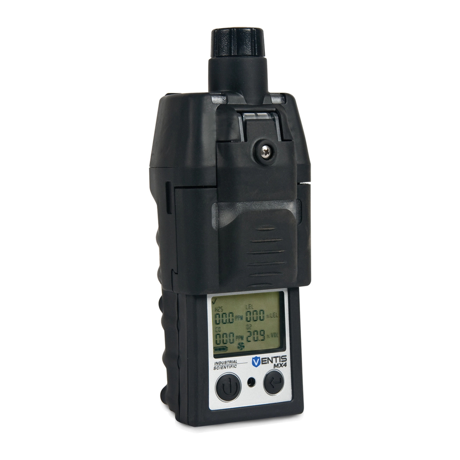
Ventis™ MX4 Product Manual ►Monitor Overview HARDWARE FEATURES AND FUNCTIONS The monitor’s case top (front of monitor) has two main sections. As shown below, the upper section contains the sensor ports. The lower section houses the user interface features, a LCD display screen and two buttons. Each feature’s general functions are noted below.
-
Page 9: Display Screen
DISPLAY SCREEN The Ventis MX4 Boot-up Screen, as shown below, serves to introduce all icons and the alpha-numeric items (e.g., 8.8.8) that can appear on the display when the monitor is in use, docked, or charging. Each display item is stationary, communicates unique information, and appears only when relevant to the task being performed.
-
Page 10
Ventis™ MX4 Product Manual Lower Explosive Limit. Display variations: “LEL” (English) “LIE” (French) “UEG” (German) Oxygen (O Nitrogen Dioxide (NO Hydrogen Sulfide (H CO H2/Low Percentage Volume: O and CH measurement unit Percentage unit for combustible gases; display variations: “% LEL” (English) “% LIE”… -
Page 11: Alarms
It is practical for the monitor user to be aware of the possible alarms prior to monitor set-up and use. The Ventis MX4 has four alarm and warning levels. A “system level” alarm generates the highest frequency tone and highest level visual and vibration signals.
-
Page 12
Ventis™ MX4 Product Manual the up arrow icon displays. A low alarm condition occurs when the concentration of gas sensed reaches the monitor’s low alarm value setting for a sensor(s). Low Alarm Screen A flashing gas concentration value* indicates which sensor(s) reading(s) is the cause for alarm. -
Page 13: Monitor Set-Up
Use and Service. BATTERY PROPERTIES AND MONITOR COMPATIBILITY Based on the customer order, the Ventis MX4 comes equipped with one of three factory installed batteries: rechargeable Lithium-ion (Li-ion), rechargeable Extended Range Lithium-ion (extended range Li-ion), or replaceable alkaline. The factory installed battery pack type is stated on the label affixed to the monitor box. Basic battery properties and acceptable monitor/battery combinations are shown below.
-
Page 14: Charging The Lithium-Ion Battery Packs
The lithium-ion battery packs are charged at the factory. As some or all of the charge may deplete before the monitor arrives or is unpacked, it is recommended that the monitor be fully charged before first time use. The lithium-ion equipped Ventis MX4 can be charged with any of the products listed below. …
-
Page 15: Power-On And -Off
POWER-ON AND -OFF To power-on the Ventis MX4, press ON/OFF/MODE and hold for three to five seconds. During the first ten to15 seconds the monitor is on, its firmware completes internal tests and the user sees or hears what is described and shown below.
-
Page 16: Configuration
Clock Settings Alarm Latch Set Date Settings Zero In-field The Ventis MX4 can be configured manually as instructed below. Any changes made take effect immediately upon exiting the configuration mode. Instructions NOTICES The configuration mode should be accessed only by safety personnel authorized to change monitor settings based on company policy.
-
Page 17: Configuration Process
Ventis™ MX4 Product Manual The configuration mode can be entered during the 20-second countdown of the power-on process. During the countdown, simultaneously press ON/OFF/MODE and ENTER, hold for three seconds, and release to enter configuration mode. (While in the configuration mode, the same button presses cause the monitor to exit configuration).
-
Page 18
Ventis™ MX4 Product Manual Press ON/OFF/MODE to bypass the zero and calibration processes and advance to one of two screens. If the installed sensor set includes H S and NO , OR, SO and NO the monitor is pre-set for standard calibration mode and the Low Alarm Set-point Screen displays. -
Page 19
Ventis™ MX4 Product Manual Press ON/OFF/MODE to bypass high alarm value set process and advance to one of two screens as noted below. Press ENTER to begin the high alarm value set process. On the display, the first sensor subject to change flashes. -
Page 20
Ventis™ MX4 Product Manual Press ON/OFF/MODE to bypass the calibration gas set process and advance to the Clock Set Screen. Press ENTER to begin the calibration gas value set process. On the display, the first sensor subject to change flashes. -
Page 21
Ventis™ MX4 Product Manual With an enabled confidence indicator, the monitor will emit a signal, every 90 seconds in gas monitoring mode, to inform the user it is operational. Press ENTER to edit the value, if needed. Press ON/OFF/MODE to set the value and advance to one of two screens. -
Page 22
Ventis™ MX4 Product Manual Sets the percentage of calibration gas the monitor expects to be exposed to. Press ENTER to edit the value, if needed; press repeatedly or hold down to speed the increment pace. Press ON/OFF/MODE to set the value and advance to the Bump Test Response Time Screen. -
Page 23
Ventis™ MX4 Product Manual Sets the elapsed time allowed between calibrations. Press ENTER to edit the value, if needed. Press ON/OFF/MODE to set the value and advance to the Calibration Days Set Screen. Calibration Due Set-point Screen Value range: one to 365 days… -
Page 24: Monitor Use And Service
Ventis™ MX4 Product Manual Disallow or allow operator-activated shutdown when the unit is in alarm. Press ENTER to edit the value, if needed. Press ON/OFF/MODE to set the value and advance to the next configuration mode screen. Shutdown In Alarm Screen…
-
Page 25: Recommendations
*If set to the default value of 20.9% or 21%, the Oxygen sensor calibrates during the zero process and toxic 1 is the first to calibrate in the calibration process. The Ventis MX4 monitor can be calibrated with any of the accessories listed. …
-
Page 26: Instructions
Ventis™ MX4 Product Manual Instructions Calibration and Bump Testing with Calibration Cup and/or Tubing Read all instructions before beginning: notices, supply check-list, gas cylinder preparation, and the complete screen- by-screen walk-through of the zero, calibrate, and bump test processes. Each process is presented in the order in which it is accessible from gas monitoring mode.
-
Page 27
Ventis™ MX4 Product Manual Prepare the gas cylinder for use According to the supply chart above, attach the correct regulator to the gas cylinder and turn clockwise to tighten. Next, choose instruction A., B., or C. based on the monitor/regulator combination in use. -
Page 28
Ventis™ MX4 Product Manual Press ENTER to begin the zero process and advance to the Zero In-process Screen. Press ON/OFF/MODE to bypass zero and calibration and advance to one of two screens. If bump test in-field is enabled, the user advances to the Bump Test Initiate Screen. -
Page 29
The monitor’s display and buttons are NOT covered. The cup’s side arms fit securely in the grooves on the sides of the monitor. The Ventis MX4 name on the calibration cup is upright and readable. The cup’s nipple points up and away from the monitor. -
Page 30
The cup fully covers the sensor ports. The monitor’s display and buttons are not covered. The cup’s side arms fit securely in the grooves on the sides of the monitor. The Ventis MX4 name on the calibration © 2014 Industrial Scientific Corporation… -
Page 31
Ventis™ MX4 Product Manual cup is upright and readable. The cup’s nipple points up and away from the monitor. Turn (counterclockwise) the regulator’s knob. As the bump test progresses, observe the display activity (left). After the bump test, the Bump Test Results Screen displays. -
Page 32: Recommended Practices For In-Field Air Sampling
The Ventis MX4 aspirated monitor is rated to sustain a continuous sample draw for up to 100 feet (30.48 m) with 0.125 inch (0.3175 cm) inside diameter sample tubing. In confined space, an air sample should be taken in four foot (1.2192 m) intervals.
-
Page 33: Service
Aspirated Monitor Battery Replacement For an aspirated monitor, two of the three Ventis MX4 battery packs can be used. The Extended Range Li-ion battery is replaced as a single part. The Alkaline battery unit consists of batteries and a pack for the batteries.
-
Page 34
Dispose of any spent batteries according to company policy. Diffusion Monitor Battery Replacement or Changeover The diffusion monitor can be used with all three Ventis MX4 battery packs. The Li-ion battery kit is a single part consisting of the monitor’s lower case bottom and the battery. It is removed from and attached to the diffusion monitor as a single item. -
Page 35
Ventis™ MX4 Product Manual ATTACHING THE EXTENDED RANGE LI-ION (OR ALKALINE) BATTERY PACK TO A DIFFUSION MONITOR. Battery Removal. Power-off the monitor. Loosen the four captive screws on the lower portion of the Case Bottom (back of the monitor. Lift the battery unit to remove; set it aside. -
Page 36: Monitor Conversion
Ventis™ MX4 Product Manual MONITOR CONVERSION To convert a diffusion monitor to an aspirated monitor, only the Extended Range Li-ion or Alkaline battery packs are approved for use. To convert an aspirated monitor to a diffusion monitor, a suspender clip, washer, and screw are recommended for use with the Li-ion battery pack.
-
Page 37
Ventis™ MX4 Product Manual Choose OPTION 1 or OPTION 2 below depending on the battery pack to be attached. OPTION 1: Attaching the Li-ion Battery Kit and its Compatible Suspender Clip Components. To properly place the Li-ion battery kit, align its contacts with the monitor’s contacts, at the monitor bottom. -
Page 38: Sensor, Sensor Water Barrier, Lcd, And Vibrating Motor Replacement
Ventis™ MX4 Product Manual SENSOR, SENSOR BARRIER, LCD, AND VIBRATING MOTOR REPLACEMENT Service instruction sets are provided below for each monitor type. Please choose, read, and then follow the appropriate instruction set . Within each set of instructions, follow those relevant to the desired task(s) and note the following.
-
Page 39
Ventis™ MX4 Product Manual Replacing the Vibrating Motor (if needed). Place the monitor’s case top face down. Lift the vibrating motor from its partition. The partition has two sections divided by a ridge. Discard the used motor. To properly place the new vibrating motor, its contact pins face the user and align with the left edge of the partition. -
Page 40: Pump Module
Ventis™ MX4 Product Manual Lift and remove the sensor barrier and gasket from the inside the monitor case top. Ensure the entire case top is free of adhesive; gently scrape, if needed. Wipe with a clean, dry, soft cloth or brush.
-
Page 41: Ventis Mx4 Three-Dimensional View Diagrams
Ventis™ MX4 Product Manual VENTIS MX4 MONITOR THREE-DIMENSIONAL DIAGRAM © 2014 Industrial Scientific Corporation…
-
Page 42
Y=3: China Ex Y=4: ANZEx Y=5: INMETRO Y=C: China KA * Item is not user replaceable. The Ventis MX4 monitor must be sent to an authorized ISC Service Center for this item to be replaced. © 2014 Industrial Scientific Corporation… -
Page 43
Ventis™ MX4 Product Manual VENTIS MX4 PUMP MODULE THREE-DIMENSIONAL DIAGRAM KEY FOR VENTIS MX4 PUMP MODULE THREE-DIMENSIONAL DIAGRAM Number Part Number (P/N) Description 17151150-X0 Ventis MX4 Pump Door Assembly X = Pump Door Assembly Color, where: 0 = Black, 1 = Orange (captive screw torque value: 55 oz. -
Page 44: Products, Specifications, And Certifications
Captive Case Screw, Torx (torque value: 55 oz-in or .39 N.m +/- 10%) * Item is not user replaceable. The Ventis MX4 Pump Module must be sent to an authorized ISC Service Center for this item to be replaced. ►Products, Specifications, and Certifications…
-
Page 45
Ventis MX4 Diffusion Soft Carrying Case, Lithium-ion Battery (black) 18109150 Ventis MX4 Diffusion Soft Carrying Case, Lithium-ion Battery (orange) 18108183 Ventis MX4 Diffusion Soft Carrying Case, Extended Range Lithium-ion Battery or Alkaline (black) 18109151 Ventis MX4 Diffusion Soft Carrying Case, Extended Range Lithium-ion Battery or Alkaline… -
Page 46: Monitor Specifications
Ventis™ MX4 Product Manual 5 = INMETRO 17148313-Y Extended Range Lithium-ion Battery Pack Y = Approvals where: 1 = UL, CSA, ATEX, IECEx, INMETRO, GOST-R, GOST-K, KOSHA, MED, and SANS 2 = MSHA 3 = China Ex 4 = ANZEx…
-
Page 47: Storage Conditions
Ventis™ MX4 Product Manual STORAGE CONDITIONS Temperature range 0−25 ºC (32−77 ºF) Humidity range 40–70% relative humidity (RH) noncondensing Pressure range 0.9–1.1 atm Maximum time Up to 6 months Note: Industrial Scientific recommends that infrequently used lithium-ion batteries be fully charged every four months.
-
Page 48: Lel And Lel Correlation Factors For Combustible Gases
Multiply the cell’s value (2.02) by the unit’s LEL reading (10%) to calculate the actual concentration of 20.2% LEL. * The combustible gas list is not a comprehensive list of all combustible gases that can be detected by the Ventis MX4. For additional information about combustible gas detection and the Ventis MX4, contact the ISC Technical Service department.
-
Page 49: Certifications
Ventis™ MX4 Product Manual CERTIFICATIONS Directive/Code Certification Marking ATEX Ex ia IIC T4 Ga and Ex ia I Ma; Equipment Group and Category II 1G and I M1; IP66; IP67 Ex ia s Zone 0 I/IIC T4; IP66; IP67 ANZEx …
-
Page 50: Warranty
►Warranty Industrial Scientific Corporation’s Ventis MX4 portable gas monitors are warranted to be free from defects in material and workmanship for a period of two years after purchase. This warranty includes the sensors, the pump, and the lithium-ion battery pack as shipped with the Ventis MX4.
-
Page 51
Ventis™ MX4 Product Manual © 2014 Industrial Scientific Corporation… -
Page 52
Ventis™ MX4 Product Manual ►Ventis MX4 Resource Center Product documentation. Online training. And more! www.indsci.com/ventis Global Locations Americas Corporate Headquarters 1001 Oakdale Road Oakdale, PA 15071-1500 Phone: +1 412-788-4353 1-800-DETECTS (338-3287) e-mail: info@indsci.com Canada Phone: +780-467-2423 e-mail: EdmontonService@indsci.com Europe/Middle East/Africa…
Описание
Предназначен для периодического одновременного измерения в воздухе рабочей зоны на открытых участках и в ограниченных и замкнутых пространствах (ОЗП) от 1 до 4 газов: кислород, горючие газы (метан или другой), диоксид азота, оксид углерода, сероводород, диоксид серы.
Ventis MX4 (Industrial Scientific Corporation (ISC)) конструктивно выполнен в одноблочном пластмассовом обрезиненном корпусе и представляет собой индивидуальный многокомпонентный автономный газоанализатор во взрывозащищённом исполнении, работающий в диффузионном или принудительном режиме отбора пробы (в зависимости от исполнения).
Маркировка взрывозащиты газоанализатора по ГОСТ 30852.0-2002 (МЭК 60079-0:1998): 0ExiаIICT4 Х / PO ExiaI Х
Прибор оснащён системой многоуровневой сигнализации: звуковой сигнал, светодиодный индикатор и вибрационный сигнал тревоги, отображение на дисплее порогов срабатывания.
Газоанализатор производит непрерывную запись данных текущих измерений с шагом 10 секунд. Прибор обеспечивает хранение информации об измерениях четырёх газочувствительных сенсоров примерно 90 дней. В регистрационный журнал заносятся сведения о 60 срабатываниях сигнализации, 30 ошибках и сбоях и 250 операциях калибровки или проверки контрольной смесью вручную с указанием времени их регистрации.
Также производится газоанализатор с измерением от 1 до 6 газов одновременно — iBrid MX6.
Газоанализатор выпускается в трёх исполнениях:
— с диффузионным отбором пробы;
— с диффузионным отбором пробы с возможностью установки пробоотборного насоса (входит в комплект поставки);
— со встроенным пробоотборным насосом (может дополнительно оснащаться телескопическим зондом и/или поплавковым зондом).
Газоанализатор MX 4 внесён в Государственный реестр средств измерений РФ, является средством измерения и поставляется Покупателям с обязательной первичной поверкой. Поверка подтверждается клеймом ОТК в паспорте на газоанализатор и внесением информации о поверке в систему АРШИН, т.е. результаты первичной поверки подтверждаются сведениями в Федеральном информационном фонде по обеспечению единства измерений.
Преимущества и особенности:
— заводские установки порогов срабатывания сигнализации могут быть изменены самостоятельно пользователем в процессе эксплуатации прибора;
— взрывобезопасная конструкция газоанализатора;
— наличие 4ёх уровней сигнализации;
— непрерывное одновременное измерение от 1 до 4 газов на протяжении 12 – 20 часов (в зависимости от применяемой аккумуляторной батареи);
— самодиагностика при включении;
— возможность работы как в диффузионном, так и в принудительном режиме отбора пробы;
— наличие жидкокристаллического монохромного цифрового дисплея с подсветкой;
— прорезиненный противоударный корпус из полимера и нержавеющей стали;
— возможность применения взаимозаменяемых датчиков разных типов: термокаталитических и электрохимических;
— совместимость с iNet и DC2 Docking Station;
— увеличенная ёмкость АКБ, использование литий-ионных или алкалиновых батарей;
— высокий уровень защиты от пыли и влаги – IP67/IP68;
— запись данных измерений в память;
— возможность переустановки порогов срабатывания самостоятельно в процессе использования газоанализатора.
Измеряемые газы, контролируемые газоанализатором
|
Вид газочувствительного сенсора
|
|
|
|
Кислород |
1 |
Только O2 (кислород) |
|
Горючие газы |
1 |
Газоанализатор может оснащаться газочувствительным датчиком для измерения ОДНОГО из следующих показателей: — НКПР (пентан); — НКПР (метан); — CH4 (0 — 5%). |
|
Токсичные газы |
2 |
Каждый из датчиков обеспечивает измерение концентрации в ОДНОМ из следующих режимов: — CO (угарный газ);
— CO/H2 — H2S (сероводород); — NO2 (диоксид азота); — SO2 (сернистый газ). |
- Home
- Brands
- Industrial Scientific
- Measuring Instruments
- Ventis MX4
- Reference Manual
Manual for Industrial Scientific Ventis MX4 Measuring Instruments (20 pages)
Specifications:
|
Industrial Scientific Ventis MX4: Read PDF Manual Online
Accompanying Data:
Industrial Scientific Ventis MX4 Measuring Instruments, Other PDF Reference Manual (Updated: Friday 16th of September 2022 11:23:42 PM)
Rating: 4.1 (rated by 21 users)
Compatible devices: Tango TX1, iTX1709-5753, AirAware, Ventis LS, GasBadge Pro, Radius BZ1, 1609, 135.
Recommended Documentation:
Industrial Scientific Ventis MX4: Text of Reference Manual
(Ocr-Read Version Summary of Contents, UPD: 16 September 2022)
-
8, Ventis™ MX4 Reference Guide © 2010 Industrial Scientific Corporation 8 Operation/Start-up Figure 1 Press and hold ON/OFF / MODE for three seconds, then release, to power-on. — V isual Test Screen Followed by brief displays of Pump Set-up Screen Software Version Screens — Countdown Screen Simultaneously press and hold ON/OFF/MODE and ENTER…
-
17, Ventis™ MX4 Reference Guide © 2010 Industrial Scientific Corporation 17 Bump Test Fail Screen The monitor must pass a calibration after a failed bump test ►Refer to Figure 3, Quick Calibration. *For a standard bump test, this series of display screens cycle for each sensor as it calibrates: apply gas, in-progress, and results screens. …
-
10, Ventis™ MX4 Reference Guide © 2010 Industrial Scientific Corporation 10 Configuration Figure 2 P r ess and hold ON/OFF/MODE for three seconds, then release, to power- on. — V isual Test Screen Followed by brief displays of Pump Set-up Screen Software Version Screens NOTE: if using an aspirated monitor, be sure the pump inlet is no…
-
3, Ventis™ MX4 Reference Guide © 2010 Industrial Scientific Corporation 3 Table of Contents Ventis MX4 Resources ………………………………………………………………………… 4 Warnings and Cautionary Statements ……………………………………………………. 5 Process Overview …………………………………………….…
-
7, Ventis™ MX4 Reference Guide © 2010 Industrial Scientific Corporation 7 Process Overview The following process charts provide an overview of four fundamental tasks: operation/startup, configuration, calibration, and functional “bump” testing. As noted previously, these charts are tools for the user who is both familiar with the manual and proficient in t…
-
6, Ventis™ MX4 Reference Guide © 2010 Industrial Scientific Corporation 6 Factors that Affect Instrument Performance Oxygen-deficient atmospheres may cause combustible gas readings to be lower than actual concentrations. Oxygen-enriched atmospheres may cause combustible gas readings to be higher than actual concentrations. Sudden changes in a…
-
9, Ventis™ MX4 Reference Guide © 2010 Industrial Scientific Corporation 9 Bump Test Initiate Screen (if enabled) Press ON/OFF/MODE to bypass bump test. Press ENTER to begin the bump test Process. ►Refer to Figure 4, Quick Bump Testing. Peak Readings Screen Press ENTER to clear the peak values, if desired. — TWA Readings Screen Press ENTER to clear the re…
-
13, Ventis™ MX4 Reference Guide © 2010 Industrial Scientific Corporation 13 Zero In- f ield Option Screen Press ENTER to edit, if needed. 0 = disable/off 1 = enable/on — Calibration In- f ield Option Screen Press ENTER to edit, if needed. 0 = disable/off 1 = enable/on — Calibration Due Alarm Press ENTER to edit, if needed. 0 = disable/off 1 = …
-
1, Multi-gas Monitor Part Number: 17152355-1 Version 2 www.indsci.com Reference Guide A companion resource for the Ventis MX4 Product Manual
… -
16, Ventis™ MX4 Reference Guide © 2010 Industrial Scientific Corporation 16 Quick Bump Testing Figure 4 Gas Monitoring Screen From the Gas Monitoring Screen, a series of presses on the ON/OFF/MODE button advance the user to the Bump Test Initiate Screen. Bump Test Initiate Screen Press ENTER to begin the bump test process. Press ON/OFF/MODE …
-
15, Ventis™ MX4 Reference Guide © 2010 Industrial Scientific Corporation 15 Calibration in Progress Screen* As toxic and LEL sensors calibrate, gas readings increase. ► After a manual calibration, be sure to STOP THE FLOW OF GAS. NOTE: After calibration, one of two sensor results screen display (pass or fail as shown in the next two rows). Sensor Results (Pas…
DOC-861d4aea:
Industrial Scientific Ventis MX4: Recommended Instructions
IMHS20701, Phoenix 335 Progress Puls FA KGE, Presario 6600 — Desktop PC, B470


-
XA00644F-A/00/B2/02.1271161825Safety InstructionsLevelflexFMP51/52/53/54/55/56/57PROFIBUS PAZone 0/1 Ex ia IIC T6 Ga/GbZone 20/21 Ex iaD 20/21 T*en — Document: XA00644F-ASafety instructions for electrical apparatus for explosion-hazardous areas Èä3zh -文档:XA00644F-A爆炸环境中电气仪表的安全指南Èä11 …
Levelflex FMP51 32
-
1Dear ClientThank you for Purchasing our HTYWS-H Electrolytic OilMoisture Analyzer. Please read the manual in detail prior to firstuse, which will help you use the equipment skillfully.Our aim is to improve and perfect thecompany’s products continually, so there may beslight differences between your purchase equipmentand its instruction manual. You can find the changesin the appendix. …
HTYWS-H 22
-
TENIVIARS @Professional Electrical andEnvironment Test & MeasurementInstruments:Battery Capacity,lmpedance Tester,TACHO Meter,LED light meter,Temperature &Humidity meter,lnfrared Thermometer,Soundlevel meter,Light meter,EMF meter,UV Lightmeter ,RF mete r ,Hot wire Anemometer ,COmeter,Anemometer ,Lan cable tester ,COzmeter ,Solar power meter ,Radiation meter,C …
TM- 4100 14
-
R8000 Series Communications System Analyzer AUTOTUNE USER GUIDE Kenwood NX Portable Kenwood NX Mobile Freedom Communication Technologies 2002 Synergy Blvd, Suite 200 Kilgore, Texas 75662 Copyright 2015 Freedom Communication Technologies All Rights Reserved Printed in U.S.A. CG-1375 Rev. B …
R8000 Series 61
-
iZ2EM Smart Energy In Wall MeterFig 1. Assembling Fig 2. Assembling This dual meter module is a transceiver which is a Z-WaveTM enabled device and is fully compatible with any Z-WaveTM enabled network. This product can be included and operated in any Z-Wave network with other Z-Wave certified devices from other manufacturers and/or other applications. And it can act as …
iZ2EM 4
-
Instruction Manual Model 4675LV Weir Monitor No part of this instruction manual may be reproduced, by any means, without the written consent of Geokon, Inc. The information contained herein is believed to be accurate and reliable. However, Geokon, Inc. assumes no responsibility for errors, omissions, or misinterpretation. The information herein is subject to change without …
4675LV 17
-
www.hannainst.comHanna Instruments reserves the right to modify the design, con-struction and appearance of its products without advance notice.WARRANTYWARRANTYWARRANTYWARRANTYWARRANTYHI 98129 and HI 98130 are warranted for oneyear against defects in workmanship and materialswhen used for their intended purpose and maintainedaccording to instructions. The electrode is war-ranted for …
HI 98129 2
-
Contents: One (1) gas bottleFOR IN-VITRO DIAGNOSTIC USE.Intended Use: The calibration gas is intended for use only in the IDEXX VetStat Analyzer.Product Description: One (1) 2-L gas bottle at 9.7 bars (<145 psi) at 21°C. Active Ingredients: 6% CO2, 14% O2, balance N2Storage and Handling: The gas bottle is stable when stored at 4°–30°C (39°–86°F) until the expiration dat …
VetStat 2
-
MANUAL DE INSTRUCCIONESOPERATING INSTRUCTIONSTACÓMETRO DIGITALDIGITAL TACHOMETERCOD. 51265ESPAÑOL …………………………. 2ENGLISH ………………………… 12GARANTIA / GUARANTEE … 21 …
EGAtronik 51265 24
Additional Information:
Popular Right Now:
Operating Impressions, Questions and Answers:
Download Product manual of Ventis MX4 Measuring Instruments for Free or View it Online on All-Guides.com.

1

2

3

4

5

6

7

8

9

10

11

12

13

14

15

16

17

18

19

20

21

22

23

24

25

26

27

28

29

30

31

32

33

34

35

36

37

38

39

40

41

42

43

44

45

46

47

48

49

50

51

52

1
Multi-gas Monitor
Product Manual
Set-up
Operation
Service
Part Number: 17152357-1
Version 11