-
Contents
-
Table of Contents
-
Troubleshooting
-
Bookmarks
Quick Links
Instruction Manual
HASXEE-IM-HS
10/2012
Gas Analyzers
X-STREAM Enhanced Series
Instruction Manual
www.EmersonProcess.com
Related Manuals for Emerson X-STREAM XE
Summary of Contents for Emerson X-STREAM XE
-
Page 1
Instruction Manual HASXEE-IM-HS 10/2012 Gas Analyzers X-STREAM Enhanced Series Instruction Manual www.EmersonProcess.com… -
Page 2
• Read all instructions prior to installing, operating, and servicing the product. • If you do not understand any of the instructions, contact your Emerson Process Management (Rosemount Analytical) representative for clarification. • Follow all warnings, cautions, and instructions marked on and supplied with the product. -
Page 3
Index ……..IDX Emerson Process Management GmbH & Co. OHG… -
Page 4: Table Of Contents
1.7.1 Field Housings XEXF for Installation in Hazardous Areas (Ex-Zones & Divisions). . .1-24 1.8 X-STREAM XEFD: Cast Aluminum Flameproof Housing ….. . .1-25 TOC-2 Emerson Process Management GmbH & Co. OHG…
-
Page 5
4.7.4 Driving Multiple Loads ……….4-36 Emerson Process Management GmbH & Co. OHG… -
Page 6
7.4.2 Manual Calibration ………..7-18 TOC-4 Emerson Process Management GmbH & Co. OHG… -
Page 7
8.4.2 Signal Connectors on XSP Board ……..8-23 Emerson Process Management GmbH & Co. OHG… -
Page 8
A.8.2 Field Housings…………A-44 Index TOC-6 Emerson Process Management GmbH & Co. OHG… -
Page 9
Sensor — Design Principle ……3-8 Emerson Process Management GmbH & Co. OHG TOC-7… -
Page 10
Fig. 4-29: Driving High-Current Loads ………4-35 TOC-8 Emerson Process Management GmbH & Co. OHG… -
Page 11
Fig. 7-25: Web Browser Measurements Screen ……..7-81 X-STREAM XEF, XDF and XEFD, Opened With Visible Front Panel..8-12 Fig. 8-1: Emerson Process Management GmbH & Co. OHG TOC-9… -
Page 12
Tab. 6-4: Digital Input Signals ……….6-72 TOC-10 Emerson Process Management GmbH & Co. OHG… -
Page 13: Introduction
Indicates an imperative operational procedure, an important condition or instruction. The symbol , together with a page number ( 6-5 ) or chapter headline ( Startup ) refers to more information, provided on the indicated page or chapter. Emerson Process Management GmbH & Co. OHG…
-
Page 14: Terms Used In This Instruction Manual
(gas) to burn. NAMUR NAMUR is an international user association of automation technology in process industries. This organisation has issued experience reports and working documents, called re- commendations (NE) and worksheets (NA). Emerson Process Management GmbH & Co. OHG…
-
Page 15: Symbols Used On And Inside The Unit
Nevertheless several surfaces may remain hot for a limited time. more detailled information available: see in- struction manual before proceeding! more detailled information available: see in- struction manual before proceeding! Emerson Process Management GmbH & Co. OHG…
-
Page 16: Symbols Used In This Manual
This symbol may also indicate information impor- tant for achieving accurate measurements. Emerson Process Management GmbH & Co. OHG…
-
Page 17: Safety Instructions
10/2012 SAFETY INSTRUCTIONS INTENDED USE STATEMENT X-STREAM XE series gas analyzers are intended to be used as analyzers for industrial purposes. They must not be used in medical, diagnostic or life support applications nor as safety devices. Using X-STREAM XE analyzers as safety devices, requiring redundant design or SIL clas- sification, is also not permitted.
-
Page 18: Authorized Personnel
• Batteries may leak, overheat or explode if not handled properly. • Do not open or try to charge a battery. • Do not expose batteries to heat or fire. Emerson Process Management GmbH & Co. OHG…
-
Page 19: Installing And Connecting The Unit
Removing covers may expose components conducting electric current. Connectors may also be energised. The unit should therefore be disconnected from the power supply before any kind of maintenance, repair or calibration Emerson Process Management GmbH & Co. OHG…
-
Page 20
Avoid inhaling exhaust gases. Connect the exhaust pipe to a suitable flue and inspect the pipes regularly for leaks. All connections must be airtight to avoid leaks; for instructions on performing a leak test. Emerson Process Management GmbH & Co. OHG… -
Page 21
NOT apply gas nor operate the internal pump before the warmup time has elapsed! Violation may result in condensation inside the gas paths or damaged pump diaphragm! HIGH TEMPERATURES Hot parts may be exposed when working on photometers and/or heated components in the unit. Emerson Process Management GmbH & Co. OHG… -
Page 22
25 % of the lower explosion limit, we RECOMMEND implementing one or more additional safety measures: • purging the unit with inert gas • stainless steel internal pipes • flame arrestors on gas inlets and outlets • infallible measuring cells. Emerson Process Management GmbH & Co. OHG S-10… -
Page 23
If this is not possible, cables must be laid in such a way as to guarantee a clearance of at least 5 mm from power cables. This clearance must be permanently secured (e.g. with cable ties). Emerson Process Management GmbH & Co. OHG S-11… -
Page 24
(CE compliance pursuant to EMC guidelines). In this case the customer or operating company functions as a system builder and must therefore ensure and declare compliance with EMC guidelines. Emerson Process Management GmbH & Co. OHG S-12… -
Page 25: Chapter 1 Technical Description
Emerson Process Management X-STREAM Enhanced (hereinafter also referred to as gases containing solvents. «X-STREAM XE») gas analyzers in brief: Special configurations (e.g. intrinsically safe or infallible measuring cells) for the analysis • compact design with easily accessible of combustible gases are also available.
-
Page 26
SD card • up to 2 GB enable logging periods up to 1 year • SD card replacable (not by operator, due to internal use by the analyzer firmware) Emerson Process Management GmbH & Co. OHG… -
Page 27
• text file programming via web browser or external computer • up-/download via USB or web browser More detailed information is provided by the related sections of this manual, or by docu- mentation, separately available. Emerson Process Management GmbH & Co. OHG… -
Page 28: Overview
NE 107 standard. For further information, Chapter 8. Graphic display “Home“ key “Enter” key 4 keys for settings and menu navigation X-STREAM Enhanced Front Panel (here X-STREAM XEGP) Fig. 1-1: Emerson Process Management GmbH & Co. OHG…
-
Page 29: Configuration Of Gas Lines
1.2.4 Tubing Unless otherwise specified, the analyzers ® are supplied with Viton or PVDF piping ⁄ in). Other materials (e.g. (ø 6/4 mm or stainless steel) can be used, depending on the application. Emerson Process Management GmbH & Co. OHG…
-
Page 30: Optional Components For Gas Lines
CHECK REQUESTS.. is set to Yes put, or automatically during autocalibration. Chapter 8 ‘Troubleshooting’). Depending on the model, up to two valve bocks can be fitted. Emerson Process Management GmbH & Co. OHG…
-
Page 31
If such sensors are installed in the unit, this installed to electronically compensate tempe- is indicated in the installed options menu rature variations ( page 3-21 ,measurement 6-88). specification). Emerson Process Management GmbH & Co. OHG… -
Page 32: Fig. 1-2: Optional Heated Area
(e.g. of Isolating cover Physical components (example) Heated moun- ting panel Cable support for The figure shows the heated signal wires area with the insulating cover removed. Fig. 1-2: Optional Heated Area Emerson Process Management GmbH & Co. OHG…
-
Page 33: Fig. 1-3: Suppressed Ranges Options
• pressure sensor. Pressure regulator Isolating box for Flow suppressed ranges sensor Pressure sensor Note! Images show optional components. Content of Images is reduced to essential. Fig. 1-3: Suppressed Ranges Options Emerson Process Management GmbH & Co. OHG…
-
Page 34: Configurations
(at least two out of five channels need to be serial tubed)! Fig. 1-4: Gas Flow Diagram: Single Channel Or in Series Emerson Process Management GmbH & Co. OHG 1-10…
-
Page 35: Interfaces
Any NE 44 status is also indicated by sym- bols appearing in the display´s 1 line. These symbols remain conformant to NE 44 even when the status relays are software assigned different functions. Emerson Process Management GmbH & Co. OHG 1-11…
-
Page 36: Modbus Interface, Ethernet
USB ports. • storage devices to the bigger port for external data and analyzer configuration storage • external computers to the smaller Mini USB port. Fig. 1-7: USB Interfaces Emerson Process Management GmbH & Co. OHG 1-12…
-
Page 37: Optional Interfaces
The different functions can be assigned via voltages of up to approx. 40 V. An open (not software menus. For a comprehensive list of wired) input has LOW potential. available functions, 6-71 . Emerson Process Management GmbH & Co. OHG 1-13…
-
Page 38: Comparison Of The Various X-Stream Enhanced Analyzer Models
Weight: ca. 8–12 kg (17.6 — 26.5 lb) Weight: ca. 11–16 kg (24.3–35.3 lb) For more detailed information: 1-16 For more detailed information: 1-18 : Limitations apply to selected measurement principles and ranges, Measurement specifications! Emerson Process Management GmbH & Co. OHG 1-14…
-
Page 39
Size: (DxHxW): max. ca. 222x512x578 mm Weight: max. ca. 25 (45) kg / 55.1 (99.2) lb Weight: max. ca. 63 kg (138.9 lb) For more detailed information: 1-20 For more detailed information: 1-25 Emerson Process Management GmbH & Co. OHG 1-15… -
Page 40: X-Stream Xegk: ½19 Inch Table-Top Unit
Any free tube fittings can be used for purging the de- vice to minimize interference from the ambient atmosphere, or when measuring corrosive and/ or flammable gases. Emerson Process Management GmbH & Co. OHG 1-16…
-
Page 41: Fig. 1-8: X-Stream Xegk — Views
AC power input with switch and fuses Standard gas in- and outlets enter 4 keys for adjustment and menu selection Carrying handle Signal connectors (some optional) Fig. 1-8: X-STREAM XEGK — Views Emerson Process Management GmbH & Co. OHG 1-17…
-
Page 42: X-Stream Xegp: 19 Inch Table-Top Or Rackmount Design
Chapter 6 ‘User interface and software menus’. Up to two digital I/O cards may be installed, where the first digital I/O card is marked «X4.1» while the second is «X4.2» on the rear Emerson Process Management GmbH & Co. OHG 1-18…
-
Page 43: Fig. 1-9: X-Stream Xegp — Details
Space for additional fittings Signal input/output connectors (some optional) Optional purge gas inlet Cover for eO or tO sensor Strain-reliefs, top view details Screw-type terminal adapters Strain-reliefs Fig. 1-9: X-STREAM XEGP — Details Emerson Process Management GmbH & Co. OHG 1-19…
-
Page 44: X-Stream Xexf: Field Housing With (Xef ) Single Or (Xdf) Dual Compartment
The wide XDF also provides more space e.g. for instal- range power supply unit mounted internally enables the analyzers to be used worldwide. lation of optional signal converter elements for system integrators. Emerson Process Management GmbH & Co. OHG 1-20…
-
Page 45: Fig. 1-10: X-Stream Xexf Field Housings- Front Views
Take care to use anchors and bolts specified to be used for the weight of the units! Take care the wall or stand the unit is intended to be installed at is solid and stable to support the weight! Emerson Process Management GmbH & Co. OHG 1-21…
-
Page 46: Fig. 1-11: X-Stream Xef — Right Side And Bottom View
Also only 2 brackets are at each com- Gas in- & outlets (max.
 partment. Cutouts, to combine 2 housings (here closed) Fig. 1-11: X-STREAM XEF — Right Side and Bottom View Emerson Process Management GmbH & Co. OHG 1-22…
 -
Page 47: Fig. 1-12: X-Stream Xef — Power Supply And Signal Terminals
Power line filter compartment. Cable glands Power supply terminals with integrated fuses Ethernet and USB connectors Fig. 1-12: X-STREAM XEF — Power Supply and Signal Terminals Emerson Process Management GmbH & Co. OHG 1-23…
-
Page 48: Field Housings Xexf For Installation In Hazardous Areas (Ex-Zones & Divisions)
Equipped with a simplified pressurization system, these field housings can be used to measure non-flammable gases in European Ex-zone 2. A protective gas (e.g. pressurized air) must be supplied when operating this model. Emerson Process Management GmbH & Co. OHG 1-24…
-
Page 49: X-Stream Xefd: Cast Aluminum Flameproof Housing
The special conditions for installing and operating analyzers in hazardous areas are not covered by this manual! Read the separate instruction manuals shipped together with instruments intended to be installed in hazardous areas! Emerson Process Management GmbH & Co. OHG 1-25…
-
Page 50: Fig. 1-13: X-Stream Xefd — Front View
In this transport transport screws for housing hinges Fig. 1-13: X-STREAM XEFD — Front View Emerson Process Management GmbH & Co. OHG 1-26…
-
Page 51: Fig. 1-14: X-Stream Xefd — Bottom View
Take care to use anchors and bolts specified to be used for the weight of the units! Take care the wall or stand the unit is intended to be installed at is solid and stable to support the weight! Emerson Process Management GmbH & Co. OHG 1-27…
-
Page 52: Fig. 1-15: X-Stream Xefd — Terminals
1 Terminals for signal cables (shown fully populated) 2 Power line filter 3 Cable inlets for power and signal cables 4 Power supply terminals with integrated fuses 5 Ethernet and USB connectors Fig. 1-15: X-STREAM XEFD — Terminals Emerson Process Management GmbH & Co. OHG 1-28…
-
Page 53: Chapter 2 Technical Data
This chapter contains all the technical details of the analyzers, divided into common and model-specific data. Common technical data page 2-2 X-STREAM XEGK page 2-6 X-STREAM XEGP page 2-12 X-STREAM XEXF (XEF, XDF) page 2-15 X-STREAM XEFD page 2-19 Emerson Process Management GmbH & Co. OHG…
-
Page 54
61010-1-04 / UL 61010-1, 2nd edition CE, based on EN 61010-1 Europe Electromagnetic compatibility CE, based on EN 61326 Europe Australia C-Tick others NAMUR Gas parameters Chapter 3 “Measuring principles” or „4.3 Gas conditioning“ on page 4-3 Emerson Process Management GmbH & Co. OHG… -
Page 55
2 Modbus interfaces Ethernet (RJ45 sockets) specification USB 1.0 1 USB connector type A, for connecting external storage devices 2 USB ports function 1 USB connector type mini AB, for connecting external computers Emerson Process Management GmbH & Co. OHG… -
Page 56
‘Maintenance request’, ‘Out of specifica- outputs) function tion’, ‘Function check’ (these signals are automatically configured Fail Safe), concentration alarms (can manually be configured Fail Safe), control signals for external valves or pumps, and many more Emerson Process Management GmbH & Co. OHG… -
Page 57
9-pin,optically isolated from analyzer elec- specification tronics 1 Interface RS232E, RS485 or Modbus function Special Interface Service Interface electrical RS232E, specification NOT optically isolated from analyzer electronics 1 Serial function Only for special trained service personnel! Emerson Process Management GmbH & Co. OHG… -
Page 58: Model-Specific Technical Data
Instruction Manual HASXEE-IM-HS X-STREAM XE 10/2012 2.2.1 Model-Specific Technical Data: X-STREAM XEGK 2.2 Model-Specific Technical Data 2.2.1 X-STREAM XEGK: ½19 Inch Tabletop Unit All dimensions in mm [in] Fig. 2-1: X-STREAM XEGK — Dimensions Emerson Process Management GmbH & Co. OHG…
-
Page 59: Fig. 2-2: X-Stream Xegk — Rear Panel And Handle Variations
Frame and handle detail Portable with handle, standard I/Os, digital I/Os, AC supply, standard gas fittings Note! The shown rear panel options are interchangable! Fig. 2-2: X-STREAM XEGK — Rear Panel and Handle Variations Emerson Process Management GmbH & Co. OHG…
-
Page 60
Ethernet: RJ45 socket; USB connectors : Limitations apply to selected measurement principles and ranges, Measurement specifications! Emerson Process Management GmbH & Co. OHG… -
Page 61: Fig. 2-3: Ups 01 Tabletop Power Supply Unit
Excess temperature protection after cooling. Output 3-pin XLR socket approx. 2.5 kg (4.8 lb) Weight Certification EN 60950, UL1950, CSA22.2 NO 950-95 Safety EN 50081-1 (emitted interference) EN 50082-2 (interfe- rence resistance), et al Emerson Process Management GmbH & Co. OHG…
-
Page 62: Fig. 2-4: Ups 01 Power Supply Unit For Rack Installation
• with rear panel, connectors to the front. Both variations are fixed to the rack by means of screws at the panels. Fig. 2-4: UPS 01 Power Supply Unit for Rack Installation Emerson Process Management GmbH & Co. OHG 2-10…
-
Page 63: Fig. 2-5: 10 A Tabletop Psu
EN 60950, EN 50178, UL1950, UL/CSA-22.2 No 950-M90 EN 50081-1, class B (emitted interference), EN 50082-2, class A (interf. resistance), et al 15 mm / 0.6″ in front and behind Recommended clearance Emerson Process Management GmbH & Co. OHG 2-11…
-
Page 64: X-Stream Xegp: 19 Inch Tabletop And Rack-Mount Models
[in] Strain relief bracket, detail (model with clamping adapters) X: Height of rear panel cover for tO2 cell: 10 mm [0.39] eO2 cell: 36 mm [1.42] Fig. 2-6: X-STREAM XEGP — Dimensions Emerson Process Management GmbH & Co. OHG 2-12…
-
Page 65
Ethernet: RJ45 socket; USB connectors : Limitations apply to selected measurement principles and ranges, Measurement specifications! Emerson Process Management GmbH & Co. OHG 2-13… -
Page 66: Fig. 2-7: X-Stream Xegp — Power Supply And Signal Connections
Fig. 2-7: Strain relief with cable shield grounding clamps (quantity varies depending on installed options) Terminal adapters (detail) Terminal adapters Fig. 2-8: X-STREAM XEGP — Signal Connections With Screw-Type Terminal Adapters (Top View) Emerson Process Management GmbH & Co. OHG 2-14…
-
Page 67: X-Stream Xexf: Field Housing With (Xef) Single Or (Xdf) Dual Compartment
X-STREAM XEXF: Field Housing With (XEF) Single or (XDF) Dual Compartment Gas fittings Cable glands Connector for potential equalization All dimensions in mm [inches in brackets] Fig. 2-9: X-STREAM XEF — Dimensions Emerson Process Management GmbH & Co. OHG 2-15…
-
Page 68: Fig. 2-10: X-Stream Xdf — Dimensions
X-STREAM XE 10/2012 2.2.3 Model-Specific Technical Data: X-STREAM XEXF Field Housings All dimensions in mm [inches in brackets] Gas fittings Connector for potential equalization Cable glands Fig. 2-10: X-STREAM XDF — Dimensions Emerson Process Management GmbH & Co. OHG 2-16…
-
Page 69
Ethernet: RJ45 socket; USB connectors Cable glands, IP 68 Cable entries permissible cable outer dia 7 … 12 mm / 0.27″ … 0.47″ : Limitations apply to selected measurement principles and ranges, Measurement specifications! Emerson Process Management GmbH & Co. OHG 2-17… -
Page 70: Fig. 2-11: X-Stream Xexf Field Housings — Power Supply Terminals / Fuse Holders
Depending on the actual analyzer configuration Analog & digital I/O terminal strips not all shown terminal strips may be installed! Max. 4 signal cables entries Fig. 2-12: X-STREAM XEXF Field Housings — Signal Terminals Emerson Process Management GmbH & Co. OHG 2-18…
-
Page 71: X-Stream Xefd: Flameproof Housing
Flame arrestors with gas fittings Cable inlets (enclosure threads: M18 x 1.5) (enclosure threads; M20 x 1.5) Eyebolt detail All dimensions in mm [inches in brackets] Fig. 2-13: X-STREAM XEFD — Dimensions Emerson Process Management GmbH & Co. OHG 2-19…
-
Page 72
Ethernet: RJ45 socket; USB connectors to be supplied by customer, see separate insturction ma- Cable entries nual for flameproof analyzers : Limitations apply to selected measurement principles and ranges, Measurement specifications! Emerson Process Management GmbH & Co. OHG 2-20… -
Page 73: Fig. 2-14: X-Stream Xefd — Power Supply Terminals / Fuse Holders
Analog & digital I/O terminal strips Depending on the actual analyzer configuration Max. 3 signal cables entries not all shown terminal strips may be installed! Fig. 2-15: X-STREAM XEFD — Signal Terminals Emerson Process Management GmbH & Co. OHG 2-21…
-
Page 74: Information On Name Plate
7 Channel 5: Gas and full scale ranges (here:O , 5 to 25 %) 8 Manufacturer´s address 9 Certification marks (XEGK, XEGP: on a separate label) 10 Electrical data (XEGK, XEGP: on rear panel) Fig. 2-16: Analyzer Name Plate (examples) Emerson Process Management GmbH & Co. OHG 2-22…
-
Page 75: Chapter 3 Measuring Principles
X-STREAM X2 gas analyzers. shown in Fig. 3-3. For NDIR a broad-band IR Using the new IntrinzX chopper wheel, the light source is used to generate the light, while reference and the measurement signal are Emerson Process Management GmbH & Co. OHG…
-
Page 76: Fig. 3-1: Intrinzx Signal Forms
The above listed IntrinzX features offer a high degree of flexibility with regards to ap- plications: Fig. 3-1: IntrinzX Signal Forms Emerson Process Management GmbH & Co. OHG…
-
Page 77: Ndir Detector
Using the divided analysis cell and the IntrinzX chopper wheel enables simultaneous detection Fig. 3-2: Gas Detector Design Principle of measurement and reference signal. Emerson Process Management GmbH & Co. OHG…
-
Page 78: Technical Implementation
9 Temperature sensor 10 Filter for pyro detector assembly 4 Filter cell 5 UV detector 11 Chopper 6 Gas detector 12 Chopper electronics 13 IR source 14 EDL Fig. 3-3: Photometer Assembly Principle Emerson Process Management GmbH & Co. OHG…
-
Page 79: Oxygen Measurement
5 Loop 10 Gas inlet 11 Gas outlet current through the platinum wire surrounding the dumbbell. This generates a compensating Fig. 3-4: Paramagnetic Oxygen Sensor — Assembly Principle Emerson Process Management GmbH & Co. OHG…
-
Page 80: Tab. 3-1: Paramagnetic Sensor — Cross Interferences (Examples)
Hydrogen +0.26 Vinyl chloride -0.77 Hydrogen bromide -0.76 Water -0.03 Xenon -1.05 Note! This data is based on a temperature of 60 °C (140 °F). Tab. 3-1: Paramagnetic Sensor — Cross Interferences (Examples) Emerson Process Management GmbH & Co. OHG…
-
Page 81: Tab. 3-2: Solvent Resistant Paramagnetic Sensor — Approved Solvents
For the solvent resistant version of this cell, lifetime and are consumables! the ‘O’ ring made of viton is replaced by a chemraz ® model. Tab. 3-2: Solvent Resistant Paramagnetic Sensor — Approved Solvents Emerson Process Management GmbH & Co. OHG…
-
Page 82: Electrochemical Measurement
8 O-Ring into holder 9 Pressure compensating volumes 10 Lid 11 Electrical connections 12 Lids 13 Current collector Fig. 3-5: Electrochemical O Sensor — Fig. 3-6: Electrochemical O Sensor — Assembly Design Principle Emerson Process Management GmbH & Co. OHG…
-
Page 83: Fig. 3-7: Electrochemical Reaction Of Oxygen Sensor
(operation at 40 °C halves lifetime). replaced to ensure accurate measurements Chapter 7 «Maintenance»). Increases or decreases in atmospheric pres- sure have the same effect as increasing or decreasing oxygen concentrations. Emerson Process Management GmbH & Co. OHG…
-
Page 84: Fig. 3-8: Cover For Eo2 Sensor Block At Rear Panel
Note for XEGP analyzers! If the XEGP analyzer features thermostate control, the eO2 sensor block is installed at the XEGP rear panel. Cover Fig. 3-8: Cover for EO2 Sensor Block At Rear Panel Emerson Process Management GmbH & Co. OHG 3-10…
-
Page 85: Electrochemical Trace Oxygen Measurement
→ 4OH cathode: sult in a damaged sensor! 2P b + O → 2P bO in total: Prolonged exposure of the sensor to air can cause extended start up time, reduction of Emerson Process Management GmbH & Co. OHG 3-11…
-
Page 86: Fig. 3-10: Cover For To2 Sensor Block At Rear Panel
Note for XEGP analyzers! If the XEGP analyzer features a thermostate control, the tO2 sensor block is installed at the XEGP rear panel. Cover Fig. 3-10: Cover for TO2 Sensor Block At Rear Panel Emerson Process Management GmbH & Co. OHG 3-12…
-
Page 87: Thermal Conductivity Measurement
2 sensors are located in the sample gas stream (R ) and Fig. 3-11: Wheatstone Bridge in a reference gas stream (R Fig. 3-11. Emerson Process Management GmbH & Co. OHG 3-13…
-
Page 88: Technical Implementation
3 PT 100 sensors 4 Metal block 4 Metal block 5 Heater for thermostatting 5 Lid Fig. 3-12: TC Cell, Exterior View , Fig. 3-13: TC Cell, Sectional View Thermal Isolation Removed Emerson Process Management GmbH & Co. OHG 3-14…
-
Page 89: Trace Moisture Measurement
Relative humidity of 100 % in- dicates the dew point is equal to the current temperature and the air is maximally saturated with water. If the dew point remains constant and temperature increases, relative humidity will decrease. Emerson Process Management GmbH & Co. OHG 3-15…
-
Page 90: Special Operating Conditions
10.8 3306 14.1 3856 18.3 4487 23.5 5208 30.2 6030 38.5 6964 48.9 8025 61.8 9226 77.6 10 583 97.1 12 113 Tab. 3-6: Dew Points and Water Content (at 1013 hPa) Emerson Process Management GmbH & Co. OHG 3-16…
-
Page 91: Accompanying Gases
Methanol no limit Methylethyl glycol no limit no limit Natural gas no limit no limit Nitric acid Nitrogen dioxide no limit Nitrous oxide no limit Tab. 3-7: Limitations on Gases Emerson Process Management GmbH & Co. OHG 3-17…
-
Page 92
Consult with EMERSON for extremely sour natural gas, >1 % H Consider sacrificial gold filter to remove mercury vapour – Consult with EMERSON. Consult with EMERSON — for impedance type sensors, recommended concentration limit of Methanol <10% of moisture concentration to be measured to ensure negligible interference effects. -
Page 93
The cell electrolyte provides ionic electrical contact between the electrodes, usually with of how hard it is working. the aid of hydrophilic separators (labelled “wetting filters” in Fig. 3-15) to allow capillary Emerson Process Management GmbH & Co. OHG 3-19… -
Page 94
% Interference related to full scale (f. s.) Interfering applied Measurement range H 0 to 50 ppm 0 to 200 ppm 0 to 2000 ppm 0.25 0.25 Tab. 3-8: Electrochemical H S Measurement — Cross Interference by Accompanying Gases Emerson Process Management GmbH & Co. OHG 3-20… -
Page 95: Measurement Specifications
In total, more than 60 gases are detectable, so the following table gives an overview only. Consult with Emerson for gases / configurations not listed. Not all data is applicable to all analyzer variations. The sample gas(es) and measuring ranges for your specific analyzer are given by the order acknowledgement and on the analyzer’s name plate label.
-
Page 96
If installed in series to another measurement system, e. g. IR channel Special conditions apply to model XEFD Note! Do not calibrate, see special calibration notes in the measurement description! Tab. 3-11: Trace Moisture — Standard Measurement Performance Specifications Emerson Process Management GmbH & Co. OHG 3-22… -
Page 97
Related to full scale Note! These sensors require oxygen and moisture to work properly within given specifications! Take care of the separate documentation accompanying the sensors! S — Standard Measurement Performance Specifications Tab. 3-13: H Emerson Process Management GmbH & Co. OHG 3-23… -
Page 98
Limited to atmospheric if internal sample pump From gas analyzer inlet at gas flow of 1.0 l/min Special conditions apply to model XEFD Tab. 3-14: Special Performance Specifications for Gas Purity Measurements (Low Ranges) Emerson Process Management GmbH & Co. OHG 3-24… -
Page 99
Related to permissible ambient temp. range Constant pressure and temperature Daily zero and span calibration requested Sample gas pressure sensor mandatory Tab. 3-15: Special Performance Specifications for Gas Purity Measurements (Suppressed Ranges) Emerson Process Management GmbH & Co. OHG 3-25… -
Page 100
All performance data are verified during the manufacturing process for each unit by the following tests: • Linearization and sensitivity test • Long term drift stability test • Climate chamber test • Cross interference test (if applicable) Emerson Process Management GmbH & Co. OHG 3-26… -
Page 101: Chapter 4 Installation
If applicable to your instrument Trace oxygen • cell (XEGK, option) special addendum manual for hazardous (if applicable) area installations • infallible containment instruction manual Fig. 4-1: X-STREAM Enhanced Analyzers — Scope of Supply Emerson Process Management GmbH & Co. OHG…
-
Page 102: Introduction
The customer must ensure that the shielding is correctly connected to the signal cable plug mity if this is legally required (e.g. European housing. Submin-d plugs and sockets must EMC guidelines). be screwed to the analyzer. Emerson Process Management GmbH & Co. OHG…
-
Page 103: Gas Conditioning
The X-STREAM field housings can optionally be fitted with heated piping to enable the use of gases with a maximum dew point of 25 °C (77 °F) — consult factory. Emerson Process Management GmbH & Co. OHG…
-
Page 104
Specifications“ section within this manual. analyzer components, if due to Perform a calibration each time a leak released into the analyzer the source of this gas (e. g. enclosure! bottle) has changed! Emerson Process Management GmbH & Co. OHG… -
Page 105: Gas Connections
The sensor must be installed before analyzer startup, according the instructions shipped with the sensor! Do not use plastic tubing for trace oxygen measurements as it can permeate oxygen from the ambient air and cause higher than expected oxygen readings. Emerson Process Management GmbH & Co. OHG…
-
Page 106: Fig. 4-3: Installation In Bypass Mode
(Fig. 4-3). Exhaust Analyzer Exhaust Pressure control valve Flow sensor Filter Sample gas pump Fig. 4-3: Installation in Bypass Mode Emerson Process Management GmbH & Co. OHG…
-
Page 107: Electrical Connections
Any break in the earth wire inside or outside the unit may cause exposure to the risk of electrocution and is therefore prohibited. Emerson Process Management GmbH & Co. OHG…
-
Page 108: Analyzer Specific Instructions For Installation
Even if you do not install your X-STREAM XEFD in an EX zone, please install the unit according to the instructions in the separate manual. X-STREAM XEGK & XEGP Installation instructions: page 4-8 X-STREAM XEXF field housings page 4-19 Notes for wiring signal inputs and outputs page 4-31 Emerson Process Management GmbH & Co. OHG…
-
Page 109: X-Stream Xegk, X-Stream Xegp
Support the instrument, when installed into a rack! Disregarding may cause per- sonal injury and damaged equipment. Alternative DC Power inlet and separate fuse Fig. 4-4: X-STREAM XEGK — Rack Mount Version Rear Panel Emerson Process Management GmbH & Co. OHG…
-
Page 110: Fig. 4-5: X-Stream Xegp — Table Top Version Rear Panel
This avoids confusion in case the analyzer ever has to be disconnected. XEGK XEGP Gas connections Max number 1 incl. & 1 separate Max for purging (incl. / separate) 2 incl. Material PVDF; stainless steel (opt.) ⁄ Sizes 6/4 mm; » Emerson Process Management GmbH & Co. OHG 4-10…
-
Page 111
The brackets are not designed accomplished by means of four screws (Fig. to carry the weight of the 4-6). instrument! Support the instrument, when rack mounting! Disregarding may cause per- sonal injury and damaged equipment. Emerson Process Management GmbH & Co. OHG 4-11… -
Page 112: Fig. 4-7: Socket X1 — Analog & Digital Outputs 1–4
Output3 (Off spec) NO Output4 (Function check) COM Output3 (Off spec) COM Note! Configuration of relay contacts as per standard factory setting (NAMUR status signals) Fig. 4-7: Socket X1 — Analog & Digital Outputs 1–4 Emerson Process Management GmbH & Co. OHG 4-12…
-
Page 113: Fig. 4-8: Plug X2 — Serial Interface
Fig. 4-9, page 4-13). outputs Then a flat flexible cable attached to the ter- minal adapter is used for connecting to the illustrated 9-pole plug. Emerson Process Management GmbH & Co. OHG 4-13…
-
Page 114: Fig. 4-9: Configuration Of Xsta Terminal Adapter
2 Connection for flat cable to plug X2 (cable not illustrated) P4.12 D0(-) TXD0(-) not used 3 Screw-type terminals Note! Consider the installation notes in section Configuration of XSTA Terminal Adapter Fig. 4-9: Emerson Process Management GmbH & Co. OHG 4-14…
-
Page 115: Fig. 4-10: Sockets X4.1 And X4.2 — Pin Configuration
Output 8, NC Output 13, NO are on the second socket (X4.2), Output 8, NO Output 13, COM Output 8, COM if installed. Fig. 4-10: Sockets X4.1 and X4.2 — Pin Configuration Emerson Process Management GmbH & Co. OHG 4-15…
-
Page 116: Fig. 4-11: Configuration Of Xstd Terminal Adapter
Output 13, COM P2.12 1 Connector for socket X4.1 / X4.2 (on reverse side) 2 Screw-type terminals Note! section 4.7 Consider the installation notes in Fig. 4-11: Configuration of XSTD Terminal Adapter Emerson Process Management GmbH & Co. OHG 4-16…
-
Page 117: Fig. 4-12: Plug X5 — Analog Inputs
BR 1 signal in current mode to input 1 *) *) alternatively set jumper P2 on electronics board XASI **) alternatively set jumper P1 on electronics board XASI Fig. 4-12: Plug X5 — Analog Inputs Emerson Process Management GmbH & Co. OHG 4-17…
-
Page 118: Fig. 4-13: Configuration Of Xsti Terminal Adapter
P2.11 Input 2 low (-) P2.12 Input 2 low (-) 1 Connector for socket X5 (on reverse side) 2 Screw-type terminals 3 Reserved for future use Fig. 4-13: Configuration of XSTI Terminal Adapter Emerson Process Management GmbH & Co. OHG 4-18…
-
Page 119: Fig. 4-14: Power Supply Connectors
For this reason we recommend to carry out a leak test, as it is described within „Chapter 7 Maintenance and other procedures“. Emerson Process Management GmbH & Co. OHG 4-19…
-
Page 120: X-Stream Xexf (Single Xef; Dual Xdf)
Take care to use anchors and bolts specified to be used for the weight of the instruments! Assure that the wall / device for installation is sufficiently attached and stable to carry the instrument! Emerson Process Management GmbH & Co. OHG 4-20…
-
Page 121: Fig. 4-16: X-Stream Xdf — Dimensions For Installation
Gas fittings Connector for potential equalization Cable glands All dimensions in mm [inches in brackets] Fig. 4-16: X-STREAM XDF — Dimensions for Installation Emerson Process Management GmbH & Co. OHG 4-21…
-
Page 122: Fig. 4-17: X-Stream Xexf Field Housings — Terminals, Cable Glands And Gas Fittings
3 Power connections with integrated fuses 7 Plugs for openings to connect housings 4 Gland for power cable 8 Ethernet connectors Fig. 4-17: X-STREAM XEXF Field Housings — Terminals, Cable Glands and Gas Fittings Emerson Process Management GmbH & Co. OHG 4-22…
-
Page 123
Feed cable through dome nut and clam- ping insert Fold braided shield over clamping insert Make sure that brai- ded shield overlaps the O-ring by ⁄ “ (2 mm) Emerson Process Management GmbH & Co. OHG 4-23… -
Page 124
Characteristics of terminals: 0.14…1.5 mm (AWG 26…AWG 16), Accepted wire gauge: end sleeves not required Skinning length: 5 mm (0.2″) Thread: 0.25 Nm (2.21 in.lb) Min. tightening torque: Emerson Process Management GmbH & Co. OHG 4-24… -
Page 125: Fig. 4-18: Terminal Block X1 — Analog Signals And Relay Outputs 1-4
Relay Outputs Analog Outputs Serial Interface Configuration of relay output termi- nals as per standard factory setting (NAMUR status signals) Fig. 4-18: Terminal Block X1 — Analog Signals and Relay Outputs 1-4 Emerson Process Management GmbH & Co. OHG 4-25…
-
Page 126: Fig. 4-19: Terminal Block X1 — Serial Interface
4.7 and the notes on installing cable glands (Data Terminal Equipment). on page 4-22. Your analyzer´s type of serial interface is marked on a label nearby the terminals (see sample above) Fig. 4-19: Terminal Block X1 — Serial Interface Emerson Process Management GmbH & Co. OHG 4-26…
-
Page 127: Fig. 4-20: Ethernet Connector
Wiring instructions can be found in the separate manual supplied with the connector. Pin 1 Pin 8 Pin no. Signal other not used Fig. 4-20: Ethernet Connector Emerson Process Management GmbH & Co. OHG 4-27…
-
Page 128: Fig. 4-21: X4: Terminal Blocks For Digital Inputs And Outputs
– Inputs 8 14 and outputs – 22, if available, are on the second adapter. Digital outputs Digital inputs Fig. 4-21: X4: Terminal Blocks for Digital Inputs and Outputs Emerson Process Management GmbH & Co. OHG 4-28…
-
Page 129: Fig. 4-22: Terminal Block X5 — Analog Input Signals
4.7 and the notes on installing cable glands on page 4-22. 1 Screw-type terminals 2 Reserved for future use Mode Mode Analog Inputs Fig. 4-22: Terminal Block X5 — Analog Input Signals Emerson Process Management GmbH & Co. OHG 4-29…
-
Page 130: Fig. 4-23: Power Supply Connections
Finally, tighten the outer dome nut to secure the power cable. Power supply cable gland Live L Neutral N Earth PE Fig. 4-23: Power Supply Connections Emerson Process Management GmbH & Co. OHG 4-30…
-
Page 131
For this reason we recommend to carry out a leak test, as it is described within „Chapter 7 Maintenance and other procedures“. Emerson Process Management GmbH & Co. OHG 4-31… -
Page 132: Notes On Wiring Signal Inputs And Outputs
• We recommend using only shielded signal cables. The shielding must be connected at both ends to the housing (Fig. 4-24). Fig. 4-24: Shielded Signal Cable, Shielding Connected At Both Ends. Emerson Process Management GmbH & Co. OHG 4-32…
-
Page 133: Fig. 4-25: Shielded Signal Cable, Shielding Connected At One End
This is advan- tageous when both units are supplied from different grids (e.g. when installed in different buildings). Fig. 4-26: Signal Cable With Double Shielding, Shieldings Connected At Alternate Ends. Emerson Process Management GmbH & Co. OHG 4-33…
-
Page 134: Fig. 4-27: Shield Connector Terminal With Cable
The shield connector must be ordered to fit the cable diameter, and can be retrofitted: Ø 1.5…6.5 mm (0.06″…0.25″) part # ETC02019 Ø 5…11 mm (0.2″…0.43″) part # ETC02020 Ø 10…17 mm (0.4″…0.66″) part # ETC02021 Ø 16…24 mm (0.63″…0.94″) part # ETC02022 Emerson Process Management GmbH & Co. OHG 4-34…
-
Page 135: Wiring Inductive Loads
(Fig. 4-28). Last Compatible filter components for standard valves are available on request. External relay Analyzer output Fig. 4-29: Driving High-Current Loads Fig. 4-28: Suppressor Diode for Inductive Loads. Emerson Process Management GmbH & Co. OHG 4-35…
-
Page 136: Driving Multiple Loads
(Fig. 4-31). Interference is Lay cables to the loads together as far as possible further reduced if a twisted multi-core (using twisted-pair cables if possible) cable is used. Fig. 4-31: Loads in Parallel Emerson Process Management GmbH & Co. OHG 4-36…
-
Page 137: Chapter 5 Startup
(containment system), to ensure the instrument is in proper condition. For instructions on how to carry out a leak test: “Performing a Leak Test“ at page 7-4. Emerson Process Management GmbH & Co. OHG…
-
Page 138: Symbols And Typographical Conventions
(here: enter enter key) Access levels: Access level 1 (user) Access level 2 (expert) Access level 3 (administrator) Access level 4 (service level) Screen shot (here: MAIN MENU) Control.. Setup.. Status.. Info.. Service.. Emerson Process Management GmbH & Co. OHG…
-
Page 139: Front Panel Elements
5.3 Front Panel Elements 5.3 Front Panel Elements any analyzer is configured with English and All X-STREAM XE gas analyzers feature an easy-to-use graphical user interface, which German language sets, while a third can op- tionally be added. Currently available or under…
-
Page 140: Keys
Abort entry Editing keys: down Mode Function Measuring Enter main menu Highlight next menu line Open the previous/next page, Browsing when currently a line beginning with / is highlighted Editing Change current parameter Emerson Process Management GmbH & Co. OHG…
-
Page 141
Measuring Enter main menu or open 2 measurement display page (if configured) Open submenu (..) Browsing Go to next menu page, when shows in last menu line Editing Move cursor 1 char to the right Emerson Process Management GmbH & Co. OHG… -
Page 142: Software
The optional unit can only be changed utilizing a setup menu. Variables shown without a co- lon cannot be edited, they are for information only. Emerson Process Management GmbH & Co. OHG…
-
Page 143
, irrespective of where the cursor right is located. To show the previous page (indicator • place the cursor in the first accessible line and press • press , irrespective of where the cursor left is located. Emerson Process Management GmbH & Co. OHG… -
Page 144
This menu does not show on single-channel units. Within menu descriptions, the following points out, that for multi-channel instruments a selec- tion is required: Multi-channel unit: In SELECT COMPONENT select the chan- nel to be … Emerson Process Management GmbH & Co. OHG… -
Page 145: Access Levels & Codes
• to select a different digit, left right 1 00000001 • to submit the code enter 2 00000002 3 00000003 • home to exit the edit mode and return to the previous display. Emerson Process Management GmbH & Co. OHG…
-
Page 146: Special Messages
Line 4: measured value of channel 4 Note! If less than four channels are installed in the Press to return unit, only the measureands for these channels are available for selection. Emerson Process Management GmbH & Co. OHG 5-10…
-
Page 147
There are also functions, that do activate a 2 lines display with additional relay, but are not shown on the display. In secondary measurement line such cases, check the STATUS menu for more information. MEASUREMENT DISPLAY Emerson Process Management GmbH & Co. OHG 5-11… -
Page 148: Selecting The Language
• enter sets this language and the display is updated accordingly. • If the selected language is not the intended, repeate the last three steps until the inten- ded language is set. Emerson Process Management GmbH & Co. OHG 5-12…
-
Page 149: Checking The Settings
Display entering a code. Contrast.. Set the preferred language for the software. Language: English Phrase Version EN1.30 Measurements.. Measurement Display.. Menu Access.. 10 Min Auto Home: 10 Min Emerson Process Management GmbH & Co. OHG 5-13…
-
Page 150: Installed Options
(channel) to enter the second menu page. Licenses «Licenses..» opens another menu where you Key 1: can check or enter license codes to unlock Key 2: optional software features. Key 3: Package None Trial Days Emerson Process Management GmbH & Co. OHG 5-14…
-
Page 151: Configuring The Display
Line 4: (Ch1…Ch4) are used. Line 5: Note! Notice the headlines of the menus showing a «1»: This indicates that you can setup more than 1 measurement display page. Emerson Process Management GmbH & Co. OHG 5-15…
-
Page 152: Calibration Setup
Zero Limit: 20.0 % Span Limit: 20.0 % when the incorrect gas is supplied (e.g. span gas calibration using zero gas), which would result in an incorrectly configured unit. Emerson Process Management GmbH & Co. OHG 5-16…
-
Page 153
If no pressure sensor is installed, enter the current ambient pressure here and adjust it, when significant changes take place: this improves the accuracy of the instrument. Pressure compensation Manual Pressure: 1013 hPa Pressure 1013 hPa Pressure Status Good Emerson Process Management GmbH & Co. OHG 5-17… -
Page 154: Setting The Analog Outputs
The following options Low Scale: 0.00 (partly dependent on the number of measu- Max Scale: 100.00 AutoScale: ring channels and sensors installed) are FailMode: Track available: 0/4 mA: 0.00 20 mA: 100.00 Hold: Emerson Process Management GmbH & Co. OHG 5-18…
-
Page 155
C). of the sensor assigned to the given compo- nent (Press2 is the pressure value of the sensor assigned to component 2). Emerson Process Management GmbH & Co. OHG 5-19… -
Page 156
Factory setting is «Outrange:» 4-20 mA and Note! The related outputs signals can be finetuned «FailMode:» LOW — 10%, unless ordered otherwise. on a second menu page, if «FailMode» is set next section). to other than Track ( Emerson Process Management GmbH & Co. OHG 5-20… -
Page 157: Tab. 5-1: Analog Output Signals Settings And Operation Modes
(20.01…21.50 mA)** Note! The application of values marked * or ** depends on the setting of «Cut Mode» Analog outputs setup menu, page 6-67). Tab. 5-1: Analog Output Signals Settings and Operation Modes Emerson Process Management GmbH & Co. OHG 5-21…
-
Page 158
Note! This behaviour may be undesireable if e.g. the unit is connected to a data acquisition system. Emerson Process Management GmbH & Co. OHG 5-22… -
Page 159: Setting Concentration Alarms
Note! HiHi und LoLo are main alarms, Hi and Lo are pre-alarms. A hysteresis avoids oscillating alarms in case the concentration is fluctuating around a threshold. Fig. 5-2: Arrangement of Concentration Thresholds Emerson Process Management GmbH & Co. OHG 5-23…
-
Page 160: Backup The Settings
• make a local backup to a protected memory Local Backup.. Factory Defaults.. area USB Backup.. • restore the factory default settings, or • make a backup to an external USB device. USB Firmware Update.. Emerson Process Management GmbH & Co. OHG 5-24…
-
Page 161
LOCAL BACKUP. Copying Data enter Busy 100 % Progress Press to return You have now completed checking the unit’s settings: • Press home to return to the MEASURE- MENT DISPLAY. Emerson Process Management GmbH & Co. OHG 5-25… -
Page 162: Perform A Calibration
5.8 Perform a Calibration We recommend to perform at least a zero calibration, after startup of the instrument, to ensure proper measuring results. Refer to Chapter 7 for a comprehensive description of calibration procedures. Emerson Process Management GmbH & Co. OHG 5-26…
-
Page 163: Chapter 6 User Interface And Software Menus
Parameter or menu line name «Control..» Access level 3 Values to be selected (administrator) Never, 1 min Value to be entered 0 … 2000 Access level 4 press key (here: (service level) enter enter key) Emerson Process Management GmbH & Co. OHG…
-
Page 164: Menu System
See next page, lower diagram. Notes! This figure applies to software revision 1.5.x and later. Numbers are page numbers of this manual, where the associated menu is explained. X-STREAM Enhanced Software Menu Structure Fig. 6-1: Emerson Process Management GmbH & Co. OHG…
-
Page 165
Instruction Manual HASXEE-IM-HS X-STREAM XE 10/2012 6.2 Menu System X-STREAM Enhanced Software menu structure (continued) Fig. 6-1: Emerson Process Management GmbH & Co. OHG… -
Page 166: Switching On
MENU and select one of the main submenus: Start functions or perform actions Control.. Setup.. Status.. Setup the instrument 6-21 Info.. Service.. Get status information 6-108 Some analyzer information 6-122 Get service information 6-126 MAIN MENU Emerson Process Management GmbH & Co. OHG…
-
Page 167: Control Menu
These lines do not appear if digital inputs are 6-71), or if used to control the pumps ( no internal pump is available. Set ranges 6-18 Handle data logger data 6-19 Data Logger.. Event/Calibration Logger.. Handle event/calibration logger data 6-20 Emerson Process Management GmbH & Co. OHG…
-
Page 168
Press enter data to the last known good data set. A confirmation screen appears, before the function is executed. Multi-channel unit: Press to enter SELECT COMPONENT, left to calibrate another channel. Emerson Process Management GmbH & Co. OHG… -
Page 169
Press enter data to the last known good data set. A confirmation screen appears, before the function is executed. Multi-channel unit: Press left to enter SELECT COMPONENT, to calibrate another channel. Emerson Process Management GmbH & Co. OHG… -
Page 170
This menu is also available in single-channel units. lines will start a In this case, the 3 and 4 zero or span calibration, while the 5 line starts the same procedure as the 2 Emerson Process Management GmbH & Co. OHG… -
Page 171
Advanced Calibration 2of2 Status.. Open a submenu to see calibration results Results.. summary for all channels 6-13 Next Automatic Calibrations.. Open a submenu to view the scheduled dates for next automatically performed calibrations 6-118 . Emerson Process Management GmbH & Co. OHG… -
Page 172
Open a submenu to see calibration status summary for all channels 6-11 Open a submenu to see calibration results summary for all channels 6-13 Multi-channel unit: Press left to enter SELECT COMPONENT, to select another channel. Emerson Process Management GmbH & Co. OHG 6-10… -
Page 173
Shows the current procedure, or Off Current Duration Prev. Duration Shows the remaining time for the current Current Step procedure Shows the time for the previous procedure Information about the step currently carried Emerson Process Management GmbH & Co. OHG 6-11… -
Page 174
Current channel´s calibration gases setup Span Gas 5000.000 ppm Current Range Range 1 Range under calibration. Applied Gas Sample gas Multi-channel unit: Press left to enter SELECT COMPONENT, to view the status for another channel. Emerson Process Management GmbH & Co. OHG 6-12… -
Page 175
Open this menu, to see an overall calibration results summary. Calibration Results Summary Result Any ZeroFail Any SpanFail Calibration Results Single.. Open a submenu to see detailed, channel specific calibration results information 6-14 Emerson Process Management GmbH & Co. OHG 6-13… -
Page 176
Success Span Date —- Calibr. Ranges None Deviations.. Open a submenu to view calibration results deviations information next page. Multi-channel unit: Press left to enter SELECT COMPONENT, to view another channel´s results. Emerson Process Management GmbH & Co. OHG 6-14… -
Page 177
«ZeroDev. Total» or «SpanDev. Total» in concentration units give the total (sum of) corrections of the corresponding calibrations since the last time, deviations have been reset ( SETUP — CALIBRATION — DEVIATIONS; 6-43) Emerson Process Management GmbH & Co. OHG 6-15… -
Page 178
SpanGas4 Blowback Applied Gas: SampleGas All Closed Flow 1.00 l/min Concentration 25.000 ppm Currently measured gas concentration. Multi-channel unit: Press left to enter SELECT COMPONENT, to change the settings for another channel. Emerson Process Management GmbH & Co. OHG 6-16… -
Page 179
Off-Specs! separately (lines 1 to 5) or simultaneously Maintenance Requests! (last line). Function Checks! Alarms! To do so, highlight the relevant line and press All States! enter Emerson Process Management GmbH & Co. OHG 6-17… -
Page 180
Lines 2 & 3 show the corresponding range limits. Line 4 shows the currently measured value. Note! To change range limits SETUP, page 6-45 Multi-channel unit: Press lefT to enter SELECT COMPONENT, to change the settings for another channel. Emerson Process Management GmbH & Co. OHG 6-18… -
Page 181
Data is written to the internal file every 30 min, or the moment, «Logging» is turned Off (SE- 6-105 ) TUP — DATA LOGGER; Total number of entries in the internal data logger file. Emerson Process Management GmbH & Co. OHG 6-19… -
Page 182
Export Calib Data to USB! Export logged calibration data to an USB Total Entries device. Note! Make sure, there´s a memory device con- nected! Total number of entries of the internal calibra- tionein logger file. Emerson Process Management GmbH & Co. OHG 6-20… -
Page 183
Setup 2of2 USB interface setup 6-103 Operation Hours Meter.. Identification.. Time.. Data logger setup 6-105 USB Interface.. Data Logger.. Event logger setup 6-107 Event Logger.. PLC.. PLC setup 6-107 Calculator.. Calculator setup 6-107 Emerson Process Management GmbH & Co. OHG 6-21… -
Page 184
10 Min Configure menu access authorizations 6-32 This parameter determines the time period without user activity, before returning to the measurement display from any submenu. Available options: Never, 1 min, 10 min Emerson Process Management GmbH & Co. OHG 6-22… -
Page 185
The display´s contrast is temperature depen- dent. If need be, re-adjust. The default value gives an acceptable result for the analyzer´s permitted operating tem- perature range. Emerson Process Management GmbH & Co. OHG 6-23… -
Page 186
Configure the parameters for Measurements Gas measurement 6-25 Component.. Temperature.. Temperature measurement 6-27 Pressure.. Flow.. Pressure measurement 6-27 Flow measurement 6-28 Note! Temperature, pressure and flow are referred to as ‘secondary measurements’. Emerson Process Management GmbH & Co. OHG 6-24… -
Page 187: Fig. 6-2: Measurement Display Elements
10.0000 Input changed. name 10.0000 Output Flow 1 0.00 l/min Secondary measurement Multi-channel unit: Press to enter SELECT COMPONENT, Fig. 6-2: Measurement Display Elements left to change the settings for another channel. Emerson Process Management GmbH & Co. OHG 6-25…
-
Page 188
The last 2 lines show how the settings affect Note! the display of measurements. Texts for units, and values for «Custom Fac- tor» and «Custom Offset» are not checked for plausibility. Any arbitrary value can be set. Emerson Process Management GmbH & Co. OHG 6-26… -
Page 189
Pressure Unit Unit: Configure the precision of pressure displays Precision: Accepted values: 0., 0.1, 0.12 XSP-P1 1013 hPa Example for the current settings. Note! Conversion factors for the different units are pre-defined. Emerson Process Management GmbH & Co. OHG 6-27… -
Page 190
1 gal = 1 US.liq.gal. = 3.7853 l Precision: 0.12 XSP-F1 1.00 l/min Configure the precision of flow displays Accepted values: 0., 0.1, 0.12 Example for the current settings. Note! Conversion factors for the different units are pre-defined. Emerson Process Management GmbH & Co. OHG 6-28… -
Page 191
Comp1 Temp1 … Temp5 Line 2: Comp2 Line 3: Comp3 Flow1 … Flow5 Line 4: Comp4 Press1 … Press5 Line 5: Flow1 CalcA … CalcD Labels.. Blank Configure the labels 6-30. Emerson Process Management GmbH & Co. OHG 6-29… -
Page 192
Due to their importance for measurement iden- tification within a network, the menu to setup There are separate DISPLAY LABELS menus tags can be found at for each MEASUREMENT DISPLAY. SETUP — IDENTI- FICATION, page 6-99. Emerson Process Management GmbH & Co. OHG 6-30… -
Page 193: Fig. 6-3: Usage Of Labels And Tags
SETUP — DISPLAY — MEASURE- LoLo alarm: Lo alarm: MENTS, page 6-25. Hi alarm: HiHi alarm: Concentration 5.000 ppm Identification of components in log files: Tags Fig. 6-3: Usage of Labels and Tags Emerson Process Management GmbH & Co. OHG 6-31…
-
Page 194: Setup Menu
MEASURE- factory-set codes. MENT DISPLAY 1 min: Levels are locked after 1 minute of inactivity. Never: Menus remain unlocked Note! Executing “Lock menus!” in CONTROL ( 6-5), immediately sets all activated locks. Emerson Process Management GmbH & Co. OHG 6-32…
-
Page 195
Valve Assignment.. Assign calibration valves; Program Sequence.. 6-38. Interval Time.. Deviations.. Program a detailled calibration sequence; 6-40. Specify interval times for automatic calibra- tions; 6-41. See (and reset) calibrations deviations infor- mation 6-43. Emerson Process Management GmbH & Co. OHG 6-33… -
Page 196
0.000 ppm Span Gas1: 500.000 ppm Span Gas2: 5000.000 ppm Span Gas3: 25000.000 ppm Span Gas4: 50000.000 ppm Note! The calibration gases units are as setup for the currently selected channel; 6-26. Emerson Process Management GmbH & Co. OHG 6-34… -
Page 197
Span Limit: 20.0 % Accepted values: 0 … 100 % (of the channel´s full range) Multi-channel unit: Press left to enter SELECT COMPONENT, to change the settings for another channel. Emerson Process Management GmbH & Co. OHG 6-35… -
Page 198
E. g. for trace moisture sensors, calibration is page 3-15 ). not permitted ( AdvCal also enables SingleAuto and Ma- nual calibrations. SingleAuto also enables Manual calibrations! Emerson Process Management GmbH & Co. OHG 6-36… -
Page 199
INSTALLED OPTIONS is set to a value other bration parameters (simulation of calibrations). than none. Multi-channel unit: Press to enter SELECT COMPONENT, left see note on page 6-38 to change the settings for another channel. Emerson Process Management GmbH & Co. OHG 6-37… -
Page 200
Take care, that measured concentrations are faulty, because the cell is filled with improper gas, if purge times are too short. Emerson Process Management GmbH & Co. OHG 6-38… -
Page 201
Blowback Valve: The 3 None back valve, and specify its purge time for the Purge Time: selected channel. Multi-channel unit: Press left to enter SELECT COMPONENT, to change the settings for another channel. Emerson Process Management GmbH & Co. OHG 6-39… -
Page 202
— a zero calibration for all channels, may show here followed by instead; 6-99 — a span calibration of range 1 of channel 1 — a span calibration of range 2 of channel 3. Emerson Process Management GmbH & Co. OHG 6-40… -
Page 203
Specify the date to start the countdown for the next interval ( next page). Time 3/22/11 15:33 Shows the time for the next start of procedure, based on the current settings. Current time. Emerson Process Management GmbH & Co. OHG 6-41… -
Page 204
Note! This procedure also updates the four lines above, to show the next calibration date as start time. Shows the time for the next start of procedure, based on the current settings. Emerson Process Management GmbH & Co. OHG 6-42… -
Page 205
10 ppm (= last calibr.) ZeroDev Total: 30 ppm (= summary of 3 calibrations, carried out within 3 weeks) Multi-channel unit: Press left to enter SELECT COMPONENT, to change the settings for a different channel. Emerson Process Management GmbH & Co. OHG 6-43… -
Page 206
NonNegat.: negative values are output as ‘0’ Setup ambient pressure for compensation; 6-60 Note! Multi-channel unit: Cut-off always is disabled during calibra- Press left to enter SELECT COMPONENT, to tions! change the settings for another channel. Emerson Process Management GmbH & Co. OHG 6-44… -
Page 207
Note! Selecting Remote or Automatic range con- trol is not possible, if identical ranges end values are specified ( 6-46)! Specify the switchover levels for up to four ranges per channel; 6-46. Emerson Process Management GmbH & Co. OHG 6-45… -
Page 208
(Yes) or not (No) Auto Ranging Range1: Range2: Specify the hysteresis for autoranging. Range3: Accepted range: 1 … 50 % Hysteresis: 10 % Switchover Levels.. Alternatively specify switchover limits for each range separately; 6-46. Emerson Process Management GmbH & Co. OHG 6-46… -
Page 209
Note! As given in the figures to the left, specifying the ‘Min.level’ of a level to be lower than the ‘Max.level’ of the level right below, defines a switching hysteresis. Emerson Process Management GmbH & Co. OHG 6-47… -
Page 210
76.9 s Shows the current measuring range. Gives the maximum possible t time, which is limited by the size of the internal sampling buffer and the sampling rates of the installed measuring principles/sensors. Emerson Process Management GmbH & Co. OHG 6-48… -
Page 211
20.000 ppm When done, enter ACTUALS (Y) to enter the Linearizer Max 110.000 ppm Status Normal corresponding actuals ( 6-52 ). The linearization status. Possible values: Normal, Underflow, Over- flow, Undefined Emerson Process Management GmbH & Co. OHG 6-49… -
Page 212
Currently measured gas concentration Measuring range, covered by the linearization settings. Linearization Linearizer Min 20.000 ppm Linearization status. Linearizer Max 110.000 ppm Status Normal Possible values: Normal, Underflow, Over- flow, Undefined Emerson Process Management GmbH & Co. OHG 6-50… -
Page 213
Lin X23: 0.000 ppm Lin X27: 0.000 ppm Lin X24: 0.000 ppm Lin X28: 0.000 ppm Lin X29: 0.000 ppm Lin X30: 0.000 ppm Lin X31: 0.000 ppm Lin X32: 0.000 ppm Emerson Process Management GmbH & Co. OHG 6-51… -
Page 214
Lin Y23: 0.000 ppm Lin Y27: 0.000 ppm Lin Y24: 0.000 ppm Lin Y28: 0.000 ppm Lin Y29: 0.000 ppm Lin Y30: 0.000 ppm Lin Y31: 0.000 ppm Lin Y32: 0.000 ppm Emerson Process Management GmbH & Co. OHG 6-52… -
Page 215
Submenu to calculate the polynomials; Calculation.. 6-54. Enter Polynomials Coefficients 6.2.3.3.3.3.1 Overflow: 10.0 % Underflow: 5.0 % Enter the coefficients here for a 4 order polynomial: RefValue 100000 ppm State Poly1 No coeffs Emerson Process Management GmbH & Co. OHG 6-53… -
Page 216
Submenu to enter actuals ( 6-52 ). Linearization setpoints Setpoints (X).. Actuals (Y).. RefPoly1: 10000 ppm RefPoly2: 10000 ppm RefPoly3: 10000 ppm RefPoly4: 10000 ppm Clear all points! Clear all entered setpoints. Emerson Process Management GmbH & Co. OHG 6-54… -
Page 217
Activated: disabled during calibrations. IF Source1.. IF Source2.. IF Source3.. IF Source4.. Up to four sources of concentration values can be configured for compensation. These submenus are exemplified on 6-56. Emerson Process Management GmbH & Co. OHG 6-55… -
Page 218
Accepted range: -1×10 … +1×10 Apply the configured settings. If the source signal is not linear, enter this submenu .to configure a fourth-order polyno- mial, 6-56. Emerson Process Management GmbH & Co. OHG 6-56… -
Page 219
IF Polynomial a2: 0.00000000 Enter up to four polynomial factors to linearize IF Polynomial a3: 0.00000000 the interfering component´s input signal with IF Polynomial a4: 0.00000000 a fourth-order polynomial of the form Emerson Process Management GmbH & Co. OHG 6-57… -
Page 220
In this line specify the averaging time. Accepted values: 0 … 120 min Average Averaging Time: 2 min Elapsed time for the next average. Next Average in 32 s Last Average 0.000 ppm Last average result. Emerson Process Management GmbH & Co. OHG 6-58… -
Page 221
Accepted range: 0.0 s … «Max. Delay time» Delay Time:: 2.0 s The acceptable maximum delay time is inter- Delay Time Max 98.0 s nally calculated, depending on the installed measuring options, and cannot be changed. Emerson Process Management GmbH & Co. OHG 6-59… -
Page 222
If a pressure sensor is installed, this line is hidden! Pressure compensation Manual Pressure: 1013 hPa Pressure 1013 hPa Pressure Status Good These lines show the pressure, currently used for pressure compensation and the status. Emerson Process Management GmbH & Co. OHG 6-60… -
Page 223
Enter the submenu for the in- or outputs you want to configure: Analog outputs: 6-62 In-/Outputs Digital outputs: 6-68 Analog Outputs.. Digital Outputs.. Digital Inputs.. Digital inputs: 6-71 Internal SHS.. Analog Inputs.. Internal sample handling system: 6-73 Analog inputs: 6-74 Emerson Process Management GmbH & Co. OHG 6-61… -
Page 224
Enter the submenu for the output you want to configure. Analog Outputs Output1.. Note! Output2.. All submenus for the analog outputs settings Output3.. Output4.. are of an identical design. Output5.. Emerson Process Management GmbH & Co. OHG 6-62… -
Page 225: Tab. 6-1: Analog Output Signals
C). of the sensor assigned to the given compo- nent (Press2 is the pressure value of the sensor assigned to component 2). Tab. 6-1: Analog Output Signals Emerson Process Management GmbH & Co. OHG 6-63…
-
Page 226
HIGH + 10%: NE 43 failure signal level: «above». Note! Factory settings are OutRange: 4-20 mA and LOW — 10%: NE 43 failure signal level: «below». FailMode: LOW — 10%, if not changed at time of order. Emerson Process Management GmbH & Co. OHG 6-64… -
Page 227: Tab. 6-2: Analog Output Failure Modes
0 mA (2.20 …3.99 mA)** (20.01 … 21.50 mA)** Note! The application of values marked * or ** depends on the setting of «Cut Mode» page 6-67). Tab. 6-2: Analog Output Failure Modes Emerson Process Management GmbH & Co. OHG 6-65…
-
Page 228
Note! This behaviour may be undesireable if e.g. the unit is connected to a data acquisition system. Emerson Process Management GmbH & Co. OHG 6-66… -
Page 229
The accepted values for «Low Cut» again depend on the setting of «OutRange»: OutRange 0-20 mA 4-20 mA -1.80…-0.01 mA 2.20…3.99 mA Low Cut 20.01…21.50 mA High Cut Emerson Process Management GmbH & Co. OHG 6-67… -
Page 230
Once the «Node» is specified, for each output • 1…4 select within the «Signal» line, what to output. Depending on the node, the list of available signals varies; next page. Emerson Process Management GmbH & Co. OHG 6-68… -
Page 231: Tab. 6-3: Digital Output Signals
Parameter «Alarms Output Failsafe» can be used to Ain2.. or 2 manually configure Failsafe all outputs assigned to ..LoLo, ..Lo, ..Hi, ..HiHi the same type of option (indexed with 6-80 Tab. 6-3: Digital Output Signals Emerson Process Management GmbH & Co. OHG 6-69…
-
Page 232
Output16 Signal: Output18 Node: System Digital Outputs (X4.2) 3of3 Output18 Signal: Output20 Node: System Output20 Signal: Output19 Node: System Output19 Signal: Output21 Node: System Output21 Signal: Output22 Node: System Output22 Signal: Emerson Process Management GmbH & Co. OHG 6-70… -
Page 233
Rising edge, or Trailing edge. Input4 Edge: Input5 Node: Input6 Node: System Input5 Function: Range1 Input6 Function: Pump1 Input5 Edge: Down Input6 Edge: Trailing Input7 Node: Input7 Function: Range1 Input7 Edge : Rising Emerson Process Management GmbH & Co. OHG 6-71… -
Page 234: Tab. 6-4: Digital Input Signals
X4.2). Input11 Function: ExtFail Input11 Edge: Input13 Node: System Input12 Node: Input13 Function: FctCheckl Input12 Function: Range1 Input13 Edge: Rising Input12 Edge: Down Input14 Node: Input14 Function: Range4 Input14 Edge: Trailing Emerson Process Management GmbH & Co. OHG 6-72…
-
Page 235
Pump1 Signal: vated when a span calibration failure occures. Pump2 Signal: Example 2: Gas2 Signal: Pump1 Signal: —> The internal signal «V2» activates the valve connected to gas inlet 2 and pump 1. Emerson Process Management GmbH & Co. OHG 6-73… -
Page 236
If the system is setup accordingly, the access code for level 3 must be entered to gain ac- cess to this menu. Analog Inputs Select the analog input you want to configure Analog Input1.. 6-75). Analog Input2.. Emerson Process Management GmbH & Co. OHG 6-74… -
Page 237
Shows the calculated input value, based on Calc. Input Value 1013 Status Good the conversion coefficients a0..a2, as speci- fied in the submenu. Input value status. Possible entries: Absent, Failure, Good, Simulated (e.g. when in test mode) Emerson Process Management GmbH & Co. OHG 6-75… -
Page 238
If both do not match, correct the coefficients. Input signal status. Possible values: Absent, Failure, Good, Simulated (e.g. when in test mode) Emerson Process Management GmbH & Co. OHG 6-76… -
Page 239
Configure the serial interface ( Serial.. 6-78) Web Server: Specify, if (On) or not (No) a web server con- Ethernet1.. nection is used. Ethernet2.. Configure «Ethernet1» or «Ethernet2» commu- commu- nication ( 6-79) Emerson Process Management GmbH & Co. OHG 6-77… -
Page 240
Enter instrument ID for network. Accepted values: 1 .. 254 Select baud rate for the serial interface. Available options: 2400, 4800, 9600, 19200 Set whether a parity bit is used. Available options: None, Even, Odd Emerson Process Management GmbH & Co. OHG 6-78… -
Page 241
Accepted values: 500 … 10,000 ms Note! At maximum 2 hosts at a time can connect to the analyzer. «MBus timeout» specifies the time interval to elapse, before a host without activity is disconnected. Emerson Process Management GmbH & Co. OHG 6-79… -
Page 242
6-85 ) Configure pressure alarms ( 6-85 ) Configure flow alarms ( 6-85 ) Alarms 2 X-STREAM XE analyzers can be upgraded Calculator A.. with optional software packages, to provide Calculator B.. four calculators (A … D). Calculator C.. Their results can be monitored to activate Calculator D.. -
Page 243
To view the current alarm states; 6-82 Multi-channel unit: Note! Press to enter SELECT COMPONENT, to left HiHi und LoLo are main alarms, change the settings for another channel. Hi and Lo are pre-alarms. Emerson Process Management GmbH & Co. OHG 6-81… -
Page 244
View Concentration Alarms States Setup.. Alarms.. Concentration.. States.. Concentration Alarms This menu gives an overview of activated LoLo Alarm: alarms, based on the currently measured Lo Alarm Hi Alarm «Concentration». HiHi Alarm Concentration 75.000 ppm Emerson Process Management GmbH & Co. OHG 6-82… -
Page 245
To view the current alarm states; 6-84 Multi-channel unit: Note! Press to enter SELECT COMPONENT, to left HiHi und LoLo are main alarms, change the settings for another channel. Hi and Lo are pre-alarms. Emerson Process Management GmbH & Co. OHG 6-83… -
Page 246
Alarms.. Average.. States.. ConcAverage Alarms LoLo Alarm This menu gives an overview of activated Lo Alarm alarms, based on the currently measured Hi Alarm HiHi Alarm «Average» of concentration. Average 468.000 ppm Emerson Process Management GmbH & Co. OHG 6-84… -
Page 247
Setup Flow Alarms Setup.. Configuring flow alarms is similiar to the pro- Alarms.. cedure for concentration alarms; 6-81 . Flow.. Note! Reasonable values for flow alarms are bet- ween 0.4 and 2.0 l/min. Emerson Process Management GmbH & Co. OHG 6-85… -
Page 248
X-STREAM XE 10/2012 6.2.3 Setup Menu 6.2.3.6.6 Setup Alarms Calculatorn Setup.. Any X-STREAM XE analyzer can be up- Alarms.. graded with optional software packages to Calculator A..D provide four calculators (A … D). The results can be monitored to activate alarms. -
Page 249
This menu gives an overview of activated alarms, based on the currently calculated LoLo Alarm Lo Alarm «Result n» (here of Calculator A). Hi Alarm HiHi Alarm Result A 468.000 Unit A Emerson Process Management GmbH & Co. OHG 6-87… -
Page 250
Installed Options 2of2 Setup flow sensor installation, 6-90 Flow.. Pressure.. Setup pressure sensor installation, 6-91 Multi-channel unit: Press to enter SELECT COMPONENT to left change the settings for a different channel. Emerson Process Management GmbH & Co. OHG 6-88… -
Page 251
Installed Options.. This menu is used to unlock software fea- Licenses.. tures, to be purchased separately. By default, X-STREAM XE analyzers provide a web browser interface and a basic data logger. 3 optional software packages are available, to upgrade the software: Enhanced: add PLC and calculator. -
Page 252
Currently measured flow. Flow Source: XSP F1 Flow 1.00 l/min SensorMin.: 0.00 l/min The sensor´s minimum and maximum limits. SensorMax.: 1.50 l/min Flow Status Good The sensor´s status. Possible entries: Good, Absent, Failure Emerson Process Management GmbH & Co. OHG 6-90… -
Page 253
Manually enter the current ambient pressure here. Note! If «Pressure source» is set to an option other than Manual, this line is hidden. Enable or disable pressure compensation for the selected channel. Available options: On, Off Emerson Process Management GmbH & Co. OHG 6-91… -
Page 254
USB Backup.. Save/restore analyzer configuration data to/ USB Firmware Update.. from external USB devices; 6-95 Update the analyzer firmware with a new version, to be provided on a connected USB device; 6-96 Emerson Process Management GmbH & Co. OHG 6-92… -
Page 255
Wait until «Progress (0..1000)» shows 1000, Busy 1000 Progress (0..1000) then press enter to return to the previous menu. Press to return Emerson Process Management GmbH & Co. OHG 6-93… -
Page 256
7/29/09 14:26 FacBack Date Restore.. Restore saved factory configuration data Undo Restore! Busy Undo a restore Progress (0..1000) Wait until «Progress (0..1000)» shows 1000, to return to LOCAL BACKUP. then press enter Emerson Process Management GmbH & Co. OHG 6-94… -
Page 257
Save the configuration data USB Backup Restore saved configuration data Save.. Restore.. Undo Restore! Undo a restore Busy Progress (0..1000) 1000 Wait until «Progress (0..1000)» shows 1000, to return to LOCAL BACKUP. then press enter Emerson Process Management GmbH & Co. OHG 6-95… -
Page 258
Now the firmware files are copied to their final destination. • Configuration files are restored from the SD card. • All passwords are reset to factory defaults! • A final analyzer reboot completes the update procedure. Emerson Process Management GmbH & Co. OHG 6-96… -
Page 259
«Reset Hours». Press enter in this line to reset the operating hours meter for the selected channel. Multi-channel unit: Press to enter SELECT COMPONENT to left change the settings for a different channel. Emerson Process Management GmbH & Co. OHG 6-97… -
Page 260
Enter a device tag here to identify the analyzer in e.g. a network Identification System Tag: Device tag Enter a plant and customer name here. Plant Name: Plant name Customer: Company name Component Tags.. Enter tags for components; 6-99 Emerson Process Management GmbH & Co. OHG 6-98… -
Page 261
6-30, to setup labels, and see examples of usage. Label 0.000 Input Gas name 0.000 Output Unit text Label Flow 1 0.00 l/min Measurement Display With Labels and Tags (example) Fig. 6-4: Emerson Process Management GmbH & Co. OHG 6-99… -
Page 262
Enter this menu to setup the analyzer time Manual Time.. manually 6-102 Time 7/7/2009 10:27 The last line shows the current analyzer time. Note! Time format is 24h (13 = 1 pm) Emerson Process Management GmbH & Co. OHG 6-100… -
Page 263
Accepted values: 0 … 23 h Time 7/7/2009 13:27 To manually sync the time, start «Synchronize Now!» The last line shows the current analyzer time. Note! Time format is 24h (13 = 1 pm) Emerson Process Management GmbH & Co. OHG 6-101… -
Page 264
Use this menu page to manually set analyzer Month: date and time. Day: Hour: Note! Minutes: Time format is 24h (13 = 1 pm) Set! Time 7/7/2009 13:29 The last line shows the current analyzer time. Emerson Process Management GmbH & Co. OHG 6-102… -
Page 265
3985.7 MB Usage Warning: 95 % Specify the usage limit for the USB stick, to Format USB Stick.. give a warning. Format an USB memory stick before using it with this analyzer 6-104 Emerson Process Management GmbH & Co. OHG 6-103… -
Page 266: Fig. 6-5: Usb File System Structure
Fig. 6-5: USB File System Structure within logger menus. Files within this directo- ry are specific only for the analyzer with the serial number of the parent directory. File with USB tools, 7-75 Emerson Process Management GmbH & Co. OHG 6-104…
-
Page 267
If not yet present, the structure as shown on 6-104 is created on the stick, without formatting. The log files can be found within the ‘logs’ directory, 6-104. 7-73 for detailed information on the con- tent of logfiles. Emerson Process Management GmbH & Co. OHG 6-105… -
Page 268
Specify which data to be exported. Concentration: Temperature: Available options: Yes, No Flow: Pressure: FieldSep: Select the field separator, separating the dif- ferent data columns in the exported text file. Available options: TAB, Semikol, Comma Emerson Process Management GmbH & Co. OHG 6-106… -
Page 269
This menu is available only, if a valid soft- ware upgrade code has been purchased 6-89 ). See the separate and entered ( software options manual for more information on this menu. Emerson Process Management GmbH & Co. OHG 6-107… -
Page 270: Status Menu
Measurement status information Alarms.. 6-111 ) Operation Hours Meter.. Time 1/02/10 13:18 Calibration status information ( 6-116 ) Alarms status information ( 6-119 ) Operation hours information ( 6-121 ) Current date & time Emerson Process Management GmbH & Co. OHG 6-108…
-
Page 271
Messages starting with strings like ‘Ch1’ are channel related, while all others are analyzer related. For a detailled description of messages, hints on causes of off-specs and recommended chapter 8 ‘Troubleshooting’. actions, Emerson Process Management GmbH & Co. OHG 6-109… -
Page 272
Function Checks 3 related. For a detailled description of messages, hints on causes of function check and recommen- chapter 8 ‘Troubleshoo- ded actions, ting’. Emerson Process Management GmbH & Co. OHG 6-110… -
Page 273
View status information on temperature sen- sors ( 6-114 ) Measurement Component.. Temperature Sensors.. View status information on pressure sensors Pressure Sensors.. 6-115 ) Flow Sensors.. View status information on flow sensors 6-115 ) Emerson Process Management GmbH & Co. OHG 6-111… -
Page 274
Secondary Variables.. Opens a submenu with information on se- condary variables (pressure, flow, …) of this channel; 6-114 Multi-channel unit: Press left to enter SELECT COMPONENT, to view the status for another channel. Emerson Process Management GmbH & Co. OHG 6-112… -
Page 275
2 must be entered to gain ac- cess to this menu. Reset Statistics Select, which statistic to reset. Note! Reset Peak! There´s no undo for these functions! Reset StdDeviation! Emerson Process Management GmbH & Co. OHG 6-113… -
Page 276
DSP-T3 0.0 °C Sensor status Absent Status Possible values: Installed, Absent, Failure. DSP-T4 0.0 °C Abset Status Temperature Sensors 2of2 AIN1 20.0 °C Status Installed AIN2 0.0 °C Absent Status Emerson Process Management GmbH & Co. OHG 6-114… -
Page 277
DSP-F3 0.0 l/min Sensor status Absent Status Possible values: Installed, Absent, Failure. DSP-F4 0.0 l/min Flow Sensors 2of2 Absent Status AIN1 0.0 l/min Status Installed AIN2 0.0 l/min Absent Status Emerson Process Management GmbH & Co. OHG 6-115… -
Page 278
View the calibration status for the current channel; 6-117. Status.. Results.. View the calibration results for the current channel; 6-110. Multi-channel unit: Press left to enter SELECT COMPONENT, to view the status for another channel. Emerson Process Management GmbH & Co. OHG 6-116… -
Page 279
This page provides calibration results for the Results… selected channel. Calibration Results Single Zero Result Success Zero Date 7/7/2009 Span Result Success Span Date 7/7/2009 CalibrRanges None Calibration result deviations for the current Deviations.. channel; 6-118. Emerson Process Management GmbH & Co. OHG 6-117… -
Page 280
CALIBRATION, and CONTROL — ADVANCED Next Automatic Calibrations.. CALIBRATION. This page provides information about sche- duled automatic calibrations. Next Automatic Calibrations Zero All 4/15/10 14:30 Zero & Span All Progr. Sequence Blowback All Emerson Process Management GmbH & Co. OHG 6-118… -
Page 281
Alarms 2 The second menu page is available only, if Calculator A.. the calculator option has been installed, and Calculator B.. then enables to view related alarm status Calculator C.. Calculator D.. information. Emerson Process Management GmbH & Co. OHG 6-119… -
Page 282
500 ppm The last line shows the current value for the selected function, e.g. the currently measured concentration. Multi-channel unit: Press left to enter SELECT COMPONENT, to view the status for another channel. Emerson Process Management GmbH & Co. OHG 6-120… -
Page 283
In SELECT COMPONENT select the chan- nel to be viewed. Operation Hours Meter MaintRequInterval 30000 h Hours of Operation 145 h Multi-channel unit: Press left to enter SELECT COMPONENT, to view the status for another channel. Emerson Process Management GmbH & Co. OHG 6-121… -
Page 284: Info Menu
Enter this submenu to see how the analyzer PLC Enabled is identified, e.g. in a network; Calculator Enabled 6-123 . Identification.. LOI Firmware V1.00 12.02.10 Phrase Version EN 1.09 Time 10/01/10 10:00 Emerson Process Management GmbH & Co. OHG 6-122…
-
Page 285
In SELECT COMPONENT select the chan- nel to be viewed. Measurement RangeAbsMin -10000 ppm RangeAbsMax 10000000 ppm Multi-channel unit: Press to enter SELECT COMPONENT left to change the settings for a different channel. Emerson Process Management GmbH & Co. OHG 6-123… -
Page 286
This menu indicates, if your analyzer features Valves None Pump None any of the listed options. DIO#1 Installed DIO#2 Installed («Package» refers to the software upgrade Anal. Outputs options; 6-89). AIN Installed Emerson Process Management GmbH & Co. OHG 6-124… -
Page 287
Tags Range1 Tag Ch1-R1 Range2 Tag Ch1-R2 Range3 Tag Ch1-R3 Range4 Tag Ch1-R4 Multi-channel unit: Press to enter SELECT COMPONENT left to change the settings for a different channel. Emerson Process Management GmbH & Co. OHG 6-125… -
Page 288: Service Menu
Rosemount Analytical Inc. 11100 Brittmoore Park Road 1 Pandan Crescent Houston, TX 77041 Singapore 128461 United States of America Singapore T +1(713) 467-6000 T +65(6777) 8211 F +1(713) 827-3328 F +65(6777) 0947 Emerson Process Management GmbH & Co. OHG 6-126…
-
Page 289: Chapter 7 Maintenance And Other Procedures
7.11 Web Browser ……….. . . 7-78 Emerson Process Management GmbH & Co. OHG…
-
Page 290: General Maintenance Information
Corrosion, leakage Corrosion, damages, firmly seated Flame arrestors Field housings (IP 66 / NEMA 4X) Corrosion, damages on enclosure and gaskets Field housings stopping plugs Firmly seated Field housings cable glands Firmly seated Emerson Process Management GmbH & Co. OHG…
-
Page 291
Depending on output signal (see details later in this sec- Electrochemical oxygen cell tion) Electrochemical TRACE oxygen cell Every six months Once a year, at least when contaminated Filter, internal Filter, external Several times a year, depending on process conditions Emerson Process Management GmbH & Co. OHG… -
Page 292: Performing A Leak Test
Max. pressure 7.25 psig approx. 5 minutes! (500 hPa)! Multi channel instruments: Analyzers with parallel tubing require separate leak tests for each gas path ! Emerson Process Management GmbH & Co. OHG…
-
Page 293: Calibration Procedures
KEY calibrations supported by internal and/or Chapter 6 — CONTROL menus, 6-5 and SETUP menus, 6-21. external valves. The analyzer automatically supplies the right gas and considers purge times. Emerson Process Management GmbH & Co. OHG…
-
Page 294: Preparing Calibrations
1 l/min), and utilizing the correct gas fitting. Ensure the warm-up time after switching on has elapsed! Warm-up time depends on installed measuring system and configuration, measurement specifications in chapter 3! Emerson Process Management GmbH & Co. OHG…
-
Page 295
Multi-channel unit: Press to enter SELECT COMPONENT left to change the settings for a different channel. When done, press to return to CALIBRA- left TION. Emerson Process Management GmbH & Co. OHG… -
Page 296
In addition: If, for example, a calibration was quest is stored and re-activated again, when aborted because of a tolerance check, the the tolerance check is enabled somewhere maintenance request is active. If the operator in the future! Emerson Process Management GmbH & Co. OHG… -
Page 297
Setup this parameter in a way to serve your needs. If you do not intend to carry out valve sup- ported calibrations, continue with 7-17. Emerson Process Management GmbH & Co. OHG… -
Page 298: Fig. 7-2: Calibration Improvement By Variable Valve Assignments
Zero spanning with fixed assignment ch1 & improvement in & & Zero spanning with time variable assignment timeline Fig. 7-2: Calibration Improvement by Variable Valve Assignments Emerson Process Management GmbH & Co. OHG 7-10…
-
Page 299
External: Open DIGITAL OUTPUTS ( XDIO2 Installed: 7-13) to assign external valves. Anal. Outputs: Int+Ext: Open both, INTSHS ( AIN Installed: 7-120) and DIGITAL OUTPUTS ( 7-12) to assign internal and external valves. Emerson Process Management GmbH & Co. OHG 7-11… -
Page 300: Fig. 7-3: Internal Valves Assignments
Fig. 7-3: Internal Valves Assignments The next step is to assign the internal valves to the channels. If there are no external val- ves to be controlled by your analyzer, continue with 7-15. Emerson Process Management GmbH & Co. OHG 7-12…
-
Page 301
Depending on the analyzer model, 1 or 2 Output11 Node: Output10 Node: System System Digital I/O extension cards can be installed. Output11 Signal: Output10 Signal: Output12 Node: System Output12 Signal: Output13 Node: System Output13 Signal: Emerson Process Management GmbH & Co. OHG 7-13… -
Page 302
(V5, V6 or V7) for the «…Signal», as shown in the lefthand figure. The next step is to assign the valves to the channels: Continue with 7-15. Emerson Process Management GmbH & Co. OHG 7-14… -
Page 303
Zero valve: will still contain other components and the Purge time: calibration will be inaccurate.). Correct assign «Correct assign» indicates, if the current as- signment is correct (Yes), or not (No). Emerson Process Management GmbH & Co. OHG 7-15… -
Page 304
& 3 are correct, go back to menu 1 and check «Correct assign». Multi-channel unit: On menu 1, press left to open SELECT COMPONENT to change the settings for a different channel. Emerson Process Management GmbH & Co. OHG 7-16… -
Page 305
7-21 ADV.CALIBRATION — ZSCALALL! Remote calibration n.a. (via Modbus or Dig IN) recommended all channels page 7-35 Unattended calibration n.a. (via interval time) required all channels page 7-39 Emerson Process Management GmbH & Co. OHG 7-17… -
Page 306: Advanced Calibration
Concentration 0.000 ppm Flow 0.00 l/min Status.. Results.. Restore! The first line gives you the choice to cancel the procedure now. Select the second line to start the calibra- tion. Emerson Process Management GmbH & Co. OHG 7-18…
-
Page 307
SELECT COMPONENT (multi channel ana- lyzer only), to perform a zero calibration for another channel, to CONTROL, where you may start a span calibration. The procedure and screens look similiar to those of a zero calibration: Emerson Process Management GmbH & Co. OHG 7-19… -
Page 308
SELECT COMPONENT (multi channel analyzer only), to perform a span calibration for another channel, press to return to the MEASUREMENT home SCREEN, to finish with manual calibration procedures. Emerson Process Management GmbH & Co. OHG 7-20… -
Page 309
For a description of how to perform all channel zero calibrations page 7-22 all channel span calibrations page 7-25 all channel zero & span calibrations page 7-28 calibrations with programmed sequences page 7-31 Emerson Process Management GmbH & Co. OHG 7-21… -
Page 310
Zero&span single.. Zero all! Span all! Zero&span all! Programmed sequence! Note! Blowback! Single channel analyzers show the same menu, with the restriction, that the term `all` relates to the single channel only! Emerson Process Management GmbH & Co. OHG 7-22… -
Page 311
Range 1 Applied gas Zero gas The procedure has finished when «Applied gas» shows Sample gas, or «Current action» in the previous screen says Ready. Press to return to the MEASUREMENT home SCREEN. Emerson Process Management GmbH & Co. OHG 7-23… -
Page 312: Fig. 7-4: Zero All Calibration Procedure Flow Diagram
1 is this channel already zeroed? Zero All Calibration Procedure Flow Diagram Fig. 7-4: Emerson Process Management GmbH & Co. OHG 7-24…
-
Page 313
Fig. 7-5 on 7-26 for a procedure flow diagram. Emerson Process Management GmbH & Co. OHG 7-25… -
Page 314
Range 1 Applied gas Zero gas The procedure has finished when ‘Applied gas’ shows Sample gas, or «Current action» in the previous screen says Ready. Press to return to the MEASUREMENT home SCREEN. Emerson Process Management GmbH & Co. OHG 7-26… -
Page 315: Fig. 7-5: Span All Calibration Procedure Flow Diagram
1 is this channel already spanned? Span All Calibration Procedure Flow Diagram Fig. 7-5: Emerson Process Management GmbH & Co. OHG 7-27…
-
Page 316
Span all! Zero&span all! Programmed sequence! Notes! Blowback! Single channel analyzers show the same menu, with the restriction, that the term `all` relates to the single channel only! Emerson Process Management GmbH & Co. OHG 7-28… -
Page 317: Fig. 7-6: Zero&Span All Calibration Procedure Flow Diagram
Zero&Span All Calibration Procedure Flow Diagram Fig. 7-6: Emerson Process Management GmbH & Co. OHG 7-29…
-
Page 318
Range 1 Applied gas Zero gas The procedure has finished when «Applied gas» shows Sample gas, or «Current action» in the previous screen says Ready. Press to return to the MEASUREMENT home SCREEN. Emerson Process Management GmbH & Co. OHG 7-30… -
Page 319
Ch1 … Ch5 the selected channel END-OF-PGRM Action29: Node15: only (depending on the END-OF-PGRM Node29: Action16: END-OF-PGRM Node16: Action30: analyzer setup, an Node30: assigned component tag may show here instead; 6-99 Page 8 Emerson Process Management GmbH & Co. OHG 7-31… -
Page 320
Span gas calibration range1 Program Sequence 2of8 (Action6) Span gas calibration range3 Action5: Rg1SpanCal Node5: Action6: Rg3SpanCal … (Action7) End of program sequence Node6: END-OF-PGRM Action7: Node7: END-OF-PGRM Action8: Node8: Emerson Process Management GmbH & Co. OHG 7-32… -
Page 321
10/2012 7.4.3 Advanced Calibration 7.4.3.5 Notes on Span Calibrating Channels With Multiple Ranges X-STREAM XE series gas analyzers sup- port up to 4 ranges per measuring channel 6-45). For valve supported calibrations, each range can be assigned an individual span gas val- 6-38 and figure to the left). -
Page 322
Zero all! also start a blowback procedure: Span all! Zero&span all! Press enter in this line to . Programmed sequence! While the procedure is active, a «Function Blowback! executing» message appears. Emerson Process Management GmbH & Co. OHG 7-34… -
Page 323
For detailled descriptions on how to perform calibrations initialized via digital inputs 7-35 calibrations initialized via Modbus, without valves 7-37 calibrations initialized via Modbus, with valves 7-37 Emerson Process Management GmbH & Co. OHG 7-35… -
Page 324: Remote Calibration
At least it must be applied in a way, that the 300 to 500 ms edge detection Emerson Process Management GmbH & Co. OHG 7-36…
-
Page 325: Fig. 7-7: Digital Inputs — Examples Of Sequences
• the detection window (300 — 500 ms after edge) for IN2 (D) begins after the zero calibration (Z2) has ended, so the span calibration (S1) is started • the span calibration (S1) is canceled by the falling edge of IN3 (E) Fig. 7-7: Digital Inputs — Examples of Sequences Emerson Process Management GmbH & Co. OHG 7-37…
-
Page 326
Section 7.3.3 ‘Advanced Calibration’ (page to not activate a span calibration without a preceding zero 7-20), with the Modbus commands replacing calibration. the manual front panel button keypresses. Emerson Process Management GmbH & Co. OHG 7-38… -
Page 327
4) (multi channel instruments only): Every time an unattended calibration is started, it is carried out for all channels! Emerson Process Management GmbH & Co. OHG 7-39… -
Page 328: Unattended Automatic Calibration
Span calibrations, preceded by zero calibrations (time interval T2), Zero all: T1 and additional zero calibrations Zero & span all: T2 (time interval T1) Fig. 7-8: Graphical Explanation of Interval Time Settings Emerson Process Management GmbH & Co. OHG 7-40…
-
Page 329
Interval: 15 h see a summary. Start time.. Next: 10/01/10 16:00 Note! Time 10/01/10 15:33 If the displayed current time is not correct, update the system setup on 6-100. Emerson Process Management GmbH & Co. OHG 7-41… -
Page 330: Verifying A Calibration
SpanGas-1 … -4, ZeroGas, SampleGas, Blowback, All closed. Flow 1.00 l/min Concentration 25.000 ppm «Flow» shows the current gas flow, while «Con- centration» should show the expected value, if the calibration is valid and correct. Emerson Process Management GmbH & Co. OHG 7-42…
-
Page 331: Restoring A Calibration
0.000 ppm to the left). Concentration 0.000 ppm Flow 0.00 l/min Press in such a line to cancel any on- enter Status.. going calibration. While canceling, a ‘Function Results.. executing’ message appears. Restore! Emerson Process Management GmbH & Co. OHG 7-43…
-
Page 332: Cross Interference Compensation
1. Select the channel for which to carry out a cross interference compensation (SETUP — MEASUREMENT) Measurement 1of2 2. On menu page 1of2 select CROSS IN- TERFERENCE. Ranges.. Damping.. Linearization.. Cross Interference.. Average.. Delay.. Emerson Process Management GmbH & Co. OHG 7-44…
-
Page 333
Adjust IF Factor! unit (e. g. ppm if Conc1…Conc5 is selected). Linearization Curve.. „Status“ shows if the interfering components signal currently is available (e. g. properly connected). Possible status values: Absent, Good. Emerson Process Management GmbH & Co. OHG 7-45… -
Page 334
• start from step 1 to configure interference compensation for another channel. Don‘t forget now to set „Activa- ted“ to the previous value after finishing the cross interference compensation setup! Emerson Process Management GmbH & Co. OHG 7-46… -
Page 335
Emerson Process Management does not take liability for accu- racy of the results and comple- teness of the contents of this spreadsheet. Emerson Process Management GmbH & Co. OHG 7-47… -
Page 336
Don‘t forget to set „Activated“ to the previous value after fi- nishing the cross interference compensation setup! If no additional sources of interference are to be configured, press home to return to the MEASUREMENT SCREEN. Emerson Process Management GmbH & Co. OHG 7-48… -
Page 337: Replacing Worn Out Sensors
(e.g. instruments with earth connectors, heating installations). This should be done periodically when working at open instruments (especially after leaving the service site, because e.g. walking on low conducting floors might cause additional ESD). Emerson Process Management GmbH & Co. OHG 7-49…
-
Page 338: Opening X-Stream Analyzers
• remove the 4 screws for the cover, (2 screws on each side of the instrument • push the cover towards the rear and re- move it. Fig. 7-10: X-STREAM XEGK Emerson Process Management GmbH & Co. OHG 7-50…
-
Page 339: Fig. 7-11: X-Stream Xexf Field Housings And Xefd — How To Open
Consider that enclosure gaskets may be frozen when the instrument is installed outdoors. Carefully open the enclosure at temperatures below -10 °C to not damage the gaskets. Damaged gaskets void the ingress protection, possibly causing property damage, personal injury or death. Emerson Process Management GmbH & Co. OHG 7-51…
-
Page 340
7.6 Replacing Worn Out Sensors Separate sections describe the replacement of the various sensors: Electrochemical oxygen sensor (eO page 7-53 Trace oxygen sensor (tO page 7-60 Trace moisture sensor (tH page 7-61 Emerson Process Management GmbH & Co. OHG 7-52… -
Page 341: Replacing The Electrochemical Oxygen-Sensor
If the electrolyte leaks due to sensor damage, put the sensor in a plastic bag so that the solution will not be smeared on other places and return the sensor to Emerson Process Management or an industrial waste management contractor.
-
Page 342
Do not disassemble or repair the sensor. Removing a sensor part or remodeling the sensor will damage the sensor or leak the electrolyte and restoration to the original condition may not be possible. Emerson Process Management GmbH & Co. OHG 7-54… -
Page 343
(supply cell for about one day with ambient air). Temporary flushing with nitrogen ) for less than 1 h (e.g. for analyzer zero- ing purpose) has no influence on measuring characteristics. Emerson Process Management GmbH & Co. OHG 7-55… -
Page 344: Fig. 7-12: Location Of The Eo
1 eO2 sensor Unit 2 Cover for rear panel installation Fig. 7-12: Location of the EO Sensor Unit If your analyzer features eO2 sensor at rear panel, continue with page 7-57. Emerson Process Management GmbH & Co. OHG 7-56…
-
Page 345: Fig. 7-13: Sensor Unit Design
Now re-assemble the sensor unit in reverse 4 Base Plate 8 Clip order, but do not yet install it into the analyzer Fig. 7-13: Sensor Unit Design as it requires a signal adjustment. Emerson Process Management GmbH & Co. OHG 7-57…
-
Page 346: Fig. 7-14: Sensor At Rear Panel
Once the output signal has been adjusted Strip P3 for sensor connection for a specific sensor, further changing the potentiometer settings will cause incorrect measuring results! Fig. 7-15: OXS Board, Top View Emerson Process Management GmbH & Co. OHG 7-58…
-
Page 347
To ensure proper disposal, send back the old sensor to the EMERSON Process Manage- ment factory (or to your local sales office) or to an industrial waste management contractor for waste disposal. Emerson Process Management GmbH & Co. OHG 7-59… -
Page 348: Replacing The Trace Oxygen Sensor
A new sensor will be provided together with detailled installation and handling instructions. Consider all information given by the replacement instructions to avoid damaging the sensor, and to achieve best possible life time! Emerson Process Management GmbH & Co. OHG 7-60…
-
Page 349: Replacing The Trace Moisture Sensor
Sensor block 30 mm Connectors: 1 sensor signal plug 2 power to sensor 3 signal to analyzer For details see appendix! Fig. 7-16: Trace Moisture Sensor Assembly Separated Emerson Process Management GmbH & Co. OHG 7-61…
-
Page 350: Cleaning The Instrument´s Outside
Moisten the lint-free cloth with a mixture of the moistened cloth. 3 parts of water and 1 part of the general • If need be dry the housing after cleaning. purpose detergent. Emerson Process Management GmbH & Co. OHG 7-62…
-
Page 351: Save / Restore Configuration Data Sets
During backup or restore processes, a pro- gress indicator menu is shown: «Busy» turns from 0 to 1. «Progress (0..1000)» shows 1000 when copying data has finished. Copying data Busy 1000 Progress (0..1000) Emerson Process Management GmbH & Co. OHG 7-63…
-
Page 352: Fig. 7-17: Relations Of Supported Data Sets, And Where To Find Further Information
(LOCAL BACKUP — SAVE, (LOCAL BACKUP — RESTORE, 7-65) 7-66) UserData configuration saved to local FRAM Fig. 7-17: Relations of Supported Data Sets, and Where to Find Further Information Emerson Process Management GmbH & Co. OHG 7-64…
-
Page 353
A screen appears to confirm the operation: Store new local backup and overwrite old one! Select Yes! and press enter to see a new Are you sure? screen, showing the current status. Yes! Emerson Process Management GmbH & Co. OHG 7-65… -
Page 354: Local Backup — Restore
A screen appears to confirm the operation: Restore from local backup! This will restart device! Select Yes! and press enter to see a new Are you sure? screen, showing the current status. Yes! Emerson Process Management GmbH & Co. OHG 7-66…
-
Page 355: Factory Defaults — Restore
Select Yes! and press to see a new enter Are you sure? screen, showing the current status. Note! Yes! All changes regarding the analyzer setup, applied after instrument was shipped, will be overwritten! Emerson Process Management GmbH & Co. OHG 7-67…
-
Page 356: Usb Backup
• Attach an USB device • Enter SETUP — USB INTERFACE (may require to enter access level 3 code) • Select «Format USB stick..» and press enter Emerson Process Management GmbH & Co. OHG 7-68…
-
Page 357
Take care to have an USB device connected Are you sure? to the analyzer´s USB port! A screen appears to confirm the operation: Yes! Select Yes! and press enter to see a new screen, showing the current status. Emerson Process Management GmbH & Co. OHG 7-69… -
Page 358
7.8 Save / Restore Configuration Data Sets The backup files are stored within the USB device’ file structure, in a subdirectory ‘con- fig’. For more information on the USB device file system structure, 6-104 Emerson Process Management GmbH & Co. OHG 7-70… -
Page 359
USB port (icon to be visible in the first menu line)! Yes! A screen appears to confirm the operation: Select Yes! and press enter to start the pro- cess. Emerson Process Management GmbH & Co. OHG 7-71… -
Page 360: Undo Restore
UsrBack date and undoes any last restore, regardless if this Restore.. was started from the current or from another. Undo restore! Busy During the undo process, a ‘Function execu- Progress ting’ message appears. Emerson Process Management GmbH & Co. OHG 7-72…
-
Page 361: Handling Log Files
The separator for the fields within an entry Flow: is specified with the last menu line: Availa- Pressure: ble options are TAB(ulator), Comma and SemiKol(on). Entries are separated by a car- FieldSep: rige return and line feed. Emerson Process Management GmbH & Co. OHG 7-73…
-
Page 362: Exporting Log Files
Data logger data delete! Cached entries Total entries The last line «Export data to USB!» enables to export the total entries to a connected USB Data Selection.. Export data to USB! device. Emerson Process Management GmbH & Co. OHG 7-74…
-
Page 363: Fig. 7-19: Subdirectory For Log Files
Data logger exports into data.log, event logger into events.log, and calibration logger into calibration.log. Several files of the same type are added by extending the file names with increasing num- bers, e.g. data001.log, data002.log, … Emerson Process Management GmbH & Co. OHG 7-75…
-
Page 364: Log Files Content
Status codes are: G = Good, F = Failure, A = Alarm, M = Maintenance, C = Check function, O = Out of specification, S = Simulate, X = Absent Fig. 7-20: Example of Log File Emerson Process Management GmbH & Co. OHG 7-76…
-
Page 365: Files On Usb Memory Device
Another file, automatically created, is called Fig. 7-21: USB File System Structure ‘xe_win_tools.zip’; 7.85 . The automatically created autorun.inf acts as # Emerson X-STREAM XE | USB-AUTORUN File a template, containing • help text, and # — Functions ————————————— •…
-
Page 366
Microsoft Windows based computer only. Chiptool for Ethernet connections, enables to remotely identify an analyzer by its IP address, without requiring front panel ac- cess. USB driver for MS Windows PC Emerson Process Management GmbH & Co. OHG 7-78… -
Page 367: Web Browser
10/01/10 14:00 Connect your computer to the network, open a web browser and enter the instrument´s IP address. If everything is configured properly, the analyzer’s logon screen shows up ( 7-81 ). Emerson Process Management GmbH & Co. OHG 7-79…
-
Page 368: Connection To Single Computer
• Click «Close» in «LAN connection properties». On your computer open a web browser and enter the instrument´s IP address. If everything is configured properly, the analyzer’s logon screen shows up ( next page ). Emerson Process Management GmbH & Co. OHG 7-80…
-
Page 369: Fig. 7-24: Web Browser Logon Screen
Click on the left most icon (question mark) in the status bar, to receive comprehensive online help on the X- STREAM XE web browser interface. Fig. 7-25: Web Browser Measurements Screen Emerson Process Management GmbH & Co. OHG 7-81…
-
Page 370
Instruction Manual HASXEE-IM-HS X-STREAM XE 10/2012 Emerson Process Management GmbH & Co. OHG 7-82… -
Page 371: Chapter 8 Troubleshooting
8.2 Problems indicated by status messages Analyzer related messages page 8-3 Channel related messages page 8-8 8.3 Problems NOT indicated by status messages page 8-12 8.4 Extended troubleshooting on components page 8-18 Emerson Process Management GmbH & Co. OHG…
-
Page 372
(e.g. during calibration). If solving a reported problem requires working inside an open instrument, take care of the sa- fety instructions, given at the beginning of this manual! Emerson Process Management GmbH & Co. OHG… -
Page 373
Function check DISK Free space warning Internal disk usage exceeded specified limit (default: 80 %) Maintenance Free space by deleting files DISK full Internal disk usage exceeded 95 % limit Maintenance Emerson Process Management GmbH & Co. OHG… -
Page 374
• Create a new factory confi- guration file Factory file open error Opening the factory configura- • Check the file system for tion file is not possible. Maintenance consistency using CHKDISK tool Emerson Process Management GmbH & Co. OHG… -
Page 375
Off-spec Limitation analog output 5 Off-spec While installing the PLC pro- Check the PLC program for PLC program error gram, a program error was syntax errors, wrong com- Maintenance discovered mands or references Emerson Process Management GmbH & Co. OHG… -
Page 376
Sensor CRC-check Failure Sensor command buffer overflow Failure Sensor failure XPSV — CPU communication Call Emerson service, if mes- failure sage shows up repeatedly Failure Sensor invalid message length Failure SENSOR RESET Maintenance Emerson Process Management GmbH & Co. OHG… -
Page 377
To do so, The attached USB storage USB stick full attach it to a computer. device has not sufficient free • Format USB device ( Maintenance memory to store data 6-104 ) Emerson Process Management GmbH & Co. OHG… -
Page 378
The activated flow monitor Flow Low • Ensure proper flow detected a too low flow accor- • Decrease limit if appropriate ding its configured low level. Maintenance Emerson Process Management GmbH & Co. OHG… -
Page 379
• Select higher range (polyno- measurement range and Range Overflow mial linearization mode only) therefore linearization curve • Adjust gas concentration to Off-spec does not apply (measuring re- measuring re- be within range sults are not reliable). Emerson Process Management GmbH & Co. OHG… -
Page 380
Off-spec pensation purposes • Restart device. The primary sensor signal is Sensor Signal Simulation • Ask service personnel to simulated for service purpo- Function check deactivate simulation. Emerson Process Management GmbH & Co. OHG 8-10… -
Page 381
• Check function of heaters Function check shows, until all components and temperature control reached their temperatures. • Wait for the procedure to Zeroing Started Zero calibration ongoing finish. • Cancel the procedure Function check Emerson Process Management GmbH & Co. OHG 8-11… -
Page 382: Fig. 8-1: X-Stream Xef, Xdf And Xefd, Opened With Visible Front Panel
(flameproof XEFD), as shown in figure 8-1. swivel to the right swivel to the top Screws to loosen Fig. 8-1: X-STREAM XEF, XDF and XEFD, Opened With Visible Front Panel Emerson Process Management GmbH & Co. OHG 8-12…
-
Page 383
Digital Outputs Not Working MEOUT» glows — check con- Properly nection to P33 Outputs 1 — 4 affected • XPSA: LED «TIMEOUT» dark — check power connection to XPSA (2-pole cable br/wht) Emerson Process Management GmbH & Co. OHG 8-13… -
Page 384
• XPSA: If red LED «TI- MEOUT» glows — check con- Internal Valves Not Working Connection failure Properly nection to P33 • XPSA: LED «TIMEOUT» dark — check power connection to XPSA (2-pole cable br/wht) Emerson Process Management GmbH & Co. OHG 8-14… -
Page 385
IR channel: • If source housing is cold: Source not connected or de- Exchange all sources in fective case of multi-channel analy- zer / replace source if need be (see service manual) Emerson Process Management GmbH & Co. OHG 8-15… -
Page 386
Pump rate too low model with higher pump rate Too Long (operate in bypass mode, page 4-5) • Check gas path and sample Gas path(s) polluted handling system for pollution • Clean gas path Emerson Process Management GmbH & Co. OHG 8-16… -
Page 387
• Replace solenoid valves • For valve control via serial interface or digital inputs: • Any valve activated? • Check gas path and sample Gas path(s) polluted handling system for pollution • Clean gas path Emerson Process Management GmbH & Co. OHG 8-17… -
Page 388: Sample Pump: Replacement Of Diaphragm
Working at opened and powered instruments means working near live parts and is subject to instructed and trained personnel only! ELECTRICAL SHOCK HAZARD Live parts are accessible when working at open instruments! Take care to observe all applicable safety instructions! Emerson Process Management GmbH & Co. OHG 8-18…
-
Page 389
(e.g. instruments with earth connectors, heating installations). This should be done periodically when working at open instruments (especially after leaving the service site, because e.g. walking on low conducting floors might cause additional ESD). Emerson Process Management GmbH & Co. OHG 8-19… -
Page 390: Fig. 8-2: X-Stream Xegp
Remove the top cover after loosening the 12 screws. If your instrument features an internal heated box, fig. 8-4 on next page for information 12 screws on top on how to open. of the instrument Fig. 8-2: X-STREAM XEGP Emerson Process Management GmbH & Co. OHG 8-20…
-
Page 391
• remove the 4 screws for the cover, 2 screws on each side of the instrument • push the cover towards the rear and re- move it. Fig. 8-3: X-STREAM XEGK Emerson Process Management GmbH & Co. OHG 8-21… -
Page 392: Fig. 8-4: X-Stream Xexf Field Housings And Xefd — How To Open
Consider that enclosure gaskets may be frozen when the instrument is installed outdoors. Carefully open the enclosure at temperatures below -10 °C to not damage the gaskets. Damaged gaskets void the ingress protection, possibly causing property damage, personal injury or death. Emerson Process Management GmbH & Co. OHG 8-22…
-
Page 393: Fig. 8-5: Xsp — Allocation Of Signal Connectors
Instruction Manual HASXEE-IM-HS X-STREAM XE 10/2012 8.4 Troubleshooting on Components 8.4.2 Signal Connectors on XSP Board Fig. 8-5: XSP — Allocation of Signal Connectors Emerson Process Management GmbH & Co. OHG 8-23…
-
Page 394
This instruction explains the procedure to replace the diaphragms of sample gas pumps (PN 42716569) used in the X-STREAM series gas analyzers. To do so you need to dismantle the pump from your analyzer. Emerson Process Management GmbH & Co. OHG 8-24… -
Page 395
8.4 Troubleshooting on Components Required parts for the spare parts kit for the pump (PN 0375946). Step 1: If applicable: Remove the screws S1 on both sides of the pump. Take off the cover. Emerson Process Management GmbH & Co. OHG 8-25… -
Page 396
Instruction Manual HASXEE-IM-HS X-STREAM XE 10/2012 8.4 Troubleshooting on Components Step 2: Remove the screws S2 and screw S3. Step 3: Take out the pump assembly. Emerson Process Management GmbH & Co. OHG 8-26… -
Page 397
Instruction Manual HASXEE-IM-HS X-STREAM XE 10/2012 8.4 Troubleshooting on Components Step 4: Mark the pump assy. before disas- sembly. Step 5: Remove the white block. Emerson Process Management GmbH & Co. OHG 8-27… -
Page 398
HASXEE-IM-HS X-STREAM XE 10/2012 8.4 Troubleshooting on Components Step 6: Remove the teflon gasket. Step 7: Remove the remaining two pump parts. Clean the white plate for the gas in- and outlet. Emerson Process Management GmbH & Co. OHG 8-28… -
Page 399
Instruction Manual HASXEE-IM-HS X-STREAM XE 10/2012 8.4 Troubleshooting on Components Clamp Step 8: Disassemble the lower block and the clamp. Loosen the screw S4 and the nut N1. Emerson Process Management GmbH & Co. OHG 8-29… -
Page 400
Remove the two washers on the dia- phragm. Step 10: Replace the old with the new dia- phragm and assemble the washers and the clamp in reverse order (step 9 and 8). Emerson Process Management GmbH & Co. OHG 8-30… -
Page 401
Instruction Manual HASXEE-IM-HS X-STREAM XE 10/2012 8.4 Troubleshooting on Components Step 11: Remove the locking springs on both sides of the white block and take out the old diaphragms on both sides. Emerson Process Management GmbH & Co. OHG 8-31… -
Page 402
1. Put the two upper plates under the steps 6 & 7 for reference). clamp ( 2. Put the white block and the new teflon gasket between the lower block and the in-outlet plate. Emerson Process Management GmbH & Co. OHG 8-32… -
Page 403
Step 14: Assemble the pump assy in reverse order. Put it in the pump housing and fix it with the screws S2. Fix the clamp with screw S3 and the black buffer. Emerson Process Management GmbH & Co. OHG 8-33… -
Page 404
8.4 Troubleshooting on Components Step 15: If applicable: Install the cover and fix it with screws S1 at both sides. Finally re-install the pump into your analy- zer, to complete the replacement of pump diaphragm. Emerson Process Management GmbH & Co. OHG 8-34… -
Page 405: Paramagnetic Oxygen Cell For Standard Applications: Adjustment Of Physical Zero
In this case skip step 2 and continue with step 3. Step 2: Open the cell cover by loosening the screw S1 at the top. Emerson Process Management GmbH & Co. OHG 8-35…
-
Page 406
If the cell itself does not provide a cover, close the instrument while checking the cell! You might have to re-adjust the zero point several times until it remains at the expected value. Emerson Process Management GmbH & Co. OHG 8-36… -
Page 407
Instruction Manual HASXEE-IM-HS X-STREAM XE 10/2012 8.4 Troubleshooting on Components Step 6: Fix the closed cell´s cover with screw This completes the zero point adjust- ment procedure. Emerson Process Management GmbH & Co. OHG 8-37… -
Page 408: Thermal Conductivity Cell: Adjustment Of Output Signal
To adjust the zero signal of this measuring cell A digital voltmeter (DVM) is required to you need to have access to both sides of the measure and adjust several voltages! related electronics board WAP 100. Emerson Process Management GmbH & Co. OHG 8-38…
-
Page 409
LB21 1-4 closed LB21 LB20 open Step 2: Switch on the analyzer. The onboard LED will light up red and green. When the warmup time has elapsed, the LED flashes green. Emerson Process Management GmbH & Co. OHG 8-39… -
Page 410
The bridge voltage depends on range and sample gas and should be bet- ween 3V and 5V. Only if the WAP 100 board has been replaced, it is necessary to adjust the voltage with potentio-meter R60. Emerson Process Management GmbH & Co. OHG 8-40… -
Page 411
Proper configuration is a result of «try and er- ror»! Change resistor and/or position until the voltage is 0 V ± 500 mV. Finally solder in the resi- stor between P11/ P17. Emerson Process Management GmbH & Co. OHG 8-41… -
Page 412
Now once more check the zero point: Apply zero gas to the analyzer. Do not disconnect the DVM: The voltage should be 0 V ± 500 mV. If it does not, repeat from step 3! Emerson Process Management GmbH & Co. OHG 8-42… -
Page 413
Check the zero point with zero gas again and perform a zero calibration. Check the full scale signal (10V at P4.5) with span gas and perform a span calibration. This step completes the adjustment of output procedure. Emerson Process Management GmbH & Co. OHG 8-43… -
Page 414
Instruction Manual HASXEE-IM-HS X-STREAM XE 10/2012 Emerson Process Management GmbH & Co. OHG 8-44… -
Page 415: Chapter 9 Modbus Functions
6-79. If no DHCP server is available, configure the For Modbus TCP/IP the analyzer is factory IP address manually 6-79. configured to support DHCP servers: The mo- ment, the powered instrument is connected Emerson Process Management GmbH & Co. OHG…
-
Page 416
Daniel Modicon Data type 8001 — 8499 equals 5001 — 5999 long word floating point 9001 — 9999 equals 6001 — 7999 the following pages for comparisons of all Daniel and Modicon registers. Emerson Process Management GmbH & Co. OHG… -
Page 417: List Of Parameters And Registers — Sorted By Tag Name
0=open sample valve; 1=open span2 Control.ApplyGas.Span2Valve1 2062 2062 Boolean R/W valve comp1 0=open sample valve; 1=open span2 Control.ApplyGas.Span2Valve2 2066 2066 Boolean R/W valve comp2 0=open sample valve; 1=open span2 Control.ApplyGas.Span2Valve3 2070 2070 Boolean R/W valve comp3 Emerson Process Management GmbH & Co. OHG…
-
Page 418
Span calibration comp1 (1=start) 2006 2006 Boolean R/W Control.Calibration.Span_2 Span calibration comp2 (1=start) 2007 2007 Boolean R/W Control.Calibration.Span_3 Span calibration comp3 (1=start) 2008 2008 Boolean R/W Control.Calibration.Span_4 Span calibration comp4 (1=start) 2009 2009 Boolean R/W Emerson Process Management GmbH & Co. OHG… -
Page 419
Float 6008 6009… Primary Variable 5 9005 Float 6010 cal proc mode comp1 (0=Disabled Service.Calibration.ChanProcMode1 3311 3311 Word 1=Manual 2=SingleAuto 3=AdvCal) cal proc mode comp2 (0=Disabled Service.Calibration.ChanProcMode2 3312 3312 Word 1=Manual 2=SingleAuto 3=AdvCal) Emerson Process Management GmbH & Co. OHG… -
Page 420
9161 Float 6322 6325… Service.Measurement.AbsMinRange2 absolute minimum range of comp2 9163 Float 6326 6329… Service.Measurement.AbsMinRange3 absolute minimum range of comp3 9165 Float 6330 6333… Service.Measurement.AbsMinRange4 absolute minimum range of comp4 9167 Float 6334 Emerson Process Management GmbH & Co. OHG… -
Page 421
9240 6481… 9241… Service.Measurement.Compensation. polynom coeffs for conc correction of Float TfactConcCoeffs1 6488 9244 temp factor comp1 6489… 9245… Service.Measurement.Compensation. polynom coeffs for conc correction of Float TfactConcCoeffs2 6496 9248 temp factor comp2 Emerson Process Management GmbH & Co. OHG… -
Page 422
Coeffs3 6424 9212 of comp3 6425… 9213… Service.Measurement.Compensation.Toff- polynom coeffs for temperature offset Float Coeffs4 6432 9216 of comp4 6433… 9217… Service.Measurement.Compensation.Toff- polynom coeffs for temperature offset Float Coeffs5 6440 9220 of comp5 Emerson Process Management GmbH & Co. OHG… -
Page 423
LinFct PolySets (0=All 1=P1 2=P2 Service.Measurement.Lin.CalcSets1 3526 3526 Word 3=P3 4=P4) comp1 LinFct PolySets (0=All 1=P1 2=P2 Service.Measurement.Lin.CalcSets2 3527 3527 Word 3=P3 4=P4) comp2 LinFct PolySets (0=All 1=P1 2=P2 Service.Measurement.Lin.CalcSets3 3528 3528 Word 3=P3 4=P4) comp3 Emerson Process Management GmbH & Co. OHG… -
Page 424
Lin. status comp4 (0=Normal 1=Under- Service.Measurement.Lin.LinearizerStatus4 3519 3519 Word flow 2=Overflow 3=Undefined) Lin. status comp5 (0=Normal 1=Under- Service.Measurement.Lin.LinearizerStatus5 3520 3520 Word flow 2=Overflow 3=Undefined) 7183… Service.Measurement.Lin.MaxValue1 9592 Float Linearizer Maximum Value of comp1 7184 Emerson Process Management GmbH & Co. OHG 9-10… -
Page 425
1=Poly2 2=Poly3 3=Poly4) 3539… 3539… polyn. set of range1..4 comp3 (0=Poly1 Service.Measurement.Lin.RangePolySet3 Word 3542 3542 1=Poly2 2=Poly3 3=Poly4) 3543… 3543… polyn. set of range1..4 comp4 (0=Poly1 Service.Measurement.Lin.RangePolySet4 Word 3546 3546 1=Poly2 2=Poly3 3=Poly4) Emerson Process Management GmbH & Co. OHG 9-11… -
Page 426
9971… Lin-Polynom. Set3-Coeffs (A0..4) for Service.Measurement.Lin.Set3Coeffs5 Float 7950 9975 comp5 7151… 9576… Lin-Polynom. Set4-Coeffs (A0..4) for Service.Measurement.Lin.Set4Coeffs1 Float 7160 9580 comp1 7351… 9676… Lin-Polynom. Set4-Coeffs (A0..4) for Service.Measurement.Lin.Set4Coeffs2 Float 7360 9680 comp2 Emerson Process Management GmbH & Co. OHG 9-12… -
Page 427
Lin-Underflow [%] for Range1..4 of Service.Measurement.Lin.UnderflowPerc3 Float 7576 9788 comp3 7769… 9885… Lin-Underflow [%] for Range1..4 of Service.Measurement.Lin.UnderflowPerc4 Float 7776 9888 comp4 7969… 9985… Lin-Underflow [%] for Range1..4 of Service.Measurement.Lin.UnderflowPerc5 Float 7976 9988 comp5 Emerson Process Management GmbH & Co. OHG 9-13… -
Page 428
Service.Status.DeviceStates.ChStateForce3 DWord R/W (b0:..) 5338 8169 5341… 8171… Forcing for comp4’s state bitfield Service.Status.DeviceStates.ChStateForce4 DWord R/W (b0:..) 5348 8174 5351… 8176… Forcing for comp5’s state bitfield Service.Status.DeviceStates.ChStateForce5 DWord R/W (b0:..) 5358 8179 Emerson Process Management GmbH & Co. OHG 9-14… -
Page 429
6120 6101… Setup.Calibration.CurrentZerogas1 9051 Float current zero gas of comp1 6102 6103… Setup.Calibration.CurrentZerogas2 9052 Float current zero gas of comp2 6104 6105… Setup.Calibration.CurrentZerogas3 9053 Float current zero gas of comp3 6106 Emerson Process Management GmbH & Co. OHG 9-15… -
Page 430
Setup.Calibration.Range2Zerogas4 9124 Float zero gas of range2 of comp4 6248 6255… Setup.Calibration.Range2Zerogas5 9128 Float zero gas of range2 of comp5 6256 6265… Setup.Calibration.Range3Spangas1 9133 Float span gas of range3 of comp1 6266 Emerson Process Management GmbH & Co. OHG 9-16… -
Page 431
Word 1=Stability) span cal method comp2 (0=Instant, Setup.Calibration.SpanMethod2 3307 3307 Word 1=Stability) span cal method comp2 (0=Instant, Setup.Calibration.SpanMethod3 3308 3308 Word 1=Stability) span cal method comp4 (0=Instant, Setup.Calibration.SpanMethod4 3309 3309 Word 1=Stability) Emerson Process Management GmbH & Co. OHG 9-17… -
Page 432
PV5 unit: 0 = Custom, ppm, ppb, Vol% Setup.Display.Component.PV_Unit5 3031 3031 Word 6301… factor to convert ppm into displayed Setup.Display.Component.PV_UnitFactor1 9151 Float 6302 custom unit1 6305… factor to convert ppm into displayed Setup.Display.Component.PV_UnitFactor2 9153 Float 6306 custom unit2 Emerson Process Management GmbH & Co. OHG 9-18… -
Page 433
3112 3112 Line 3 3113… 3113… displayed label of measure display 1, Setup.Display.MeasDisplay.Dis1Label4 String 3116 3116 Line 4 3117… 3117… displayed label of measure display 1, Setup.Display.MeasDisplay.Dis1Label5 String 3120 3120 Line 5 Emerson Process Management GmbH & Co. OHG 9-19… -
Page 434
Setup.In/Outputs.AO.AdjustStart1 9183 Float 6366 output1 6373… fine adjustment for start range of Setup.In/Outputs.AO.AdjustStart2 9187 Float 6374 output2 6381… fine adjustment for start range of Setup.In/Outputs.AO.AdjustStart3 9191 Float 6382 output3 Emerson Process Management GmbH & Co. OHG 9-20… -
Page 435
Behavior on errors output4 (0=Track Setup.In/Outputs.AO.FailMode4 3289 3289 Word 1=-10%Start 2=+10%End) Behavior on errors output5 (0=Track Setup.In/Outputs.AO.FailMode5 3294 3294 Word 1=-10%Start 2=+10%End) 6583… Setup.In/Outputs.AO.HighCutOff1 9292 Float higher cut off (mA) for analog output1 6584 Emerson Process Management GmbH & Co. OHG 9-21… -
Page 436
3281 Word assigned signal output3 Setup.In/Outputs.AO.SignalAsgn4 3286 3286 Word assigned signal output4 Setup.In/Outputs.AO.SignalAsgn5 3291 3291 Word assigned signal output5 6361… level where analoge output scaling Setup.In/Outputs.AO.StartRange1 9181 Float 6362 starts on output1 Emerson Process Management GmbH & Co. OHG 9-22… -
Page 437
3169 Word Setup.In/Outputs.DO.Node_DO14 node of DigOut14 / XDIO2 Out1 3181 3181 Word Setup.In/Outputs.DO.Node_DO15 node of DigOut15 / XDIO2 Out2 3182 3182 Word Setup.In/Outputs.DO.Node_DO16 node of DigOut16 / XDIO2 Out3 3183 3183 Word Emerson Process Management GmbH & Co. OHG 9-23… -
Page 438
Setup.In/Outputs.SHS.Node_Gas3 node of SHS GasOut3 3203 3203 Word Setup.In/Outputs.SHS.Node_Gas4 node of SHS GasOut4 3204 3204 Word Setup.In/Outputs.SHS.Node_Gas5 node of SHS GasOut5 3205 3205 Word Setup.In/Outputs.SHS.Node_Gas6 node of SHS GasOut6 3206 3206 Word Emerson Process Management GmbH & Co. OHG 9-24… -
Page 439
6180 6195… Setup.Measurement.EndOfRange2_4 9098 Float end of range2 of comp4 6196 6211… Setup.Measurement.EndOfRange2_5 9106 Float end of range2 of comp5 6212 6151… Setup.Measurement.EndOfRange3_1 9076 Float end of range3 of comp1 6152 Emerson Process Management GmbH & Co. OHG 9-25… -
Page 440
6142 6157… Setup.Measurement.StartOfRange1_2 9079 Float start of range1 of comp2 6158 6173… Setup.Measurement.StartOfRange1_3 9087 Float start of range1 of comp3 6174 6189… Setup.Measurement.StartOfRange1_4 9095 Float start of range1 of comp4 6190 Emerson Process Management GmbH & Co. OHG 9-26… -
Page 441
Compute cross interference factor Setup.Measurement.XIntf.ComputeFactor5 3480 3480 Word comp5 (0=Src1, 1=Src2 etc.) Enable cross interference compensa- Setup.Measurement.XIntf.Enable1 3471 3471 Word tion for comp1 Enable cross interference compensa- Setup.Measurement.XIntf.Enable2 3472 3472 Word tion for comp2 Emerson Process Management GmbH & Co. OHG 9-27… -
Page 442
Setup.Measurement.XIntf.SignalStates3 Word 4062 4062 for comp3 4063… 4063… Cross interfere signal value states1..4 Setup.Measurement.XIntf.SignalStates4 Word 4066 4066 for comp4 4067… 4067… Cross interfere signal value states1..4 Setup.Measurement.XIntf.SignalStates5 Word 4070 4070 for comp5 Emerson Process Management GmbH & Co. OHG 9-28… -
Page 443
(N0) state bitfield (b0:..) Status.DeviceStates.DeviceState 5188 8094 6909… Status.Diagnostics.AfterLinConce1 9455 Float after linear. conc component1 6910 6923… 9462 Float after linear. conc component2 Status.Diagnostics.AfterLinConce2 6924 6937… Status.Diagnostics.AfterLinConce3 9469 Float after linear. conc component3 6938 Emerson Process Management GmbH & Co. OHG 9-29… -
Page 444
ADC of measure-side component4 6034 6037… Status.Diagnostics.RawMeasConce5 9019 Float raw ADC of measure-side component5 6038 6011… Status.Diagnostics.RawQuotConce1 9006 Float raw ADC quotient of component1 6012 6013… Status.Diagnostics.RawQuotConce2 9007 Float raw ADC quotient of component2 6014 Emerson Process Management GmbH & Co. OHG 9-30… -
Page 445
DWord RO Status.NamurStates.FailAlarmComp2 8029 5058 nent2 related 5065… NamurFailure alarms that are compo- DWord RO Status.NamurStates.FailAlarmComp3 8033 5066 nent3 related 5073… NamurFailure alarms that are compo- DWord RO Status.NamurStates.FailAlarmComp4 8037 5074 nent4 related Emerson Process Management GmbH & Co. OHG 9-31… -
Page 446
Namur MaintRequ alarms that are com- DWord RO Status.NamurStates.MaintRequAlarmComp5 8043 5086 ponent5 related 5045… NamurMaintRequ alarms that are DWord RO Status.NamurStates.MaintRequAlarmDev 8023 5046 device related NAMUR sum state bit-field (b0:F b1:M Status.NamurStates.NamurAlarm 4001 4001 Word b2:S b3:C) Emerson Process Management GmbH & Co. OHG 9-32… -
Page 447
6067… Status.Pressure4 9034 Float pressure of comp4 6068 6069… 9035 Float pressure of comp5 Status.Pressure5 6070 6081… Status.Temperature1 9041 Float temperature of comp1 6082 6083… Status.Temperature2 9042 Float temperature of comp2 6084 Emerson Process Management GmbH & Co. OHG 9-33… -
Page 448
Tag Name Address Description Type Access Modicon Daniel 6085… Status.Temperature3 9043 Float temperature of comp3 6086 6087… Status.Temperature4 9044 Float temperature of comp4 6088 6089… Status.Temperature5 9045 Float temperature of comp5 6090 Emerson Process Management GmbH & Co. OHG 9-34… -
Page 449: List Of Parameters And Registers — Sorted By Daniel Registers
Boolean R/W 0=open sample valve; 1=open span4 valve comp1 2065 2065 Control.ApplyGas.Span1Valve2 Boolean R/W 0=open sample valve; 1=open span1 valve comp2 2066 2066 Control.ApplyGas.Span2Valve2 Boolean R/W 0=open sample valve; 1=open span2 valve comp2 Emerson Process Management GmbH & Co. OHG 9-35…
-
Page 450
PV4 unit: 0 = Custom, ppm, ppb, Vol% 3026 3026 Word Unit4 Setup.Display.Component.PV_ PV5 unit: 0 = Custom, ppm, ppb, Vol% 3031 3031 Word Unit5 Setup.Display.Component.Preci- 3036 3036 Word decimal points displayed for component1 sion1 Emerson Process Management GmbH & Co. OHG 9-36… -
Page 451
3167 Word Setup.In/Outputs.DO.Node_DO12 Word node of DigOut12 / XDIO1 Out8 3168 3168 Setup.In/Outputs.DO.Node_DO13 Word node of DigOut13 / XDIO1 Out9 3169 3169 Setup.In/Outputs.DO.Signal_DO5 signal of DigOut5 / XDIO1 Out1 3171 3171 Word Emerson Process Management GmbH & Co. OHG 9-37… -
Page 452
3210 3210 Word node of SHS Pump1 Pump2 Setup.In/Outputs.SHS.Signal_Gas1 Word signal of SHS GasOut1 3211 3211 Setup.In/Outputs.SHS.Signal_Gas2 Word signal of SHS GasOut2 3212 3212 Setup.In/Outputs.SHS.Signal_Gas3 Word signal of SHS GasOut3 3213 3213 Emerson Process Management GmbH & Co. OHG 9-38… -
Page 453
3270 3270 Setup.In/Outputs.AO.SignalAsgn1 Word 3271 3271 assigned signal output1 Setup.In/Outputs.AO.OutRange1 3272 3272 Word range of output1 (0=0..20mA 1=4-20mA) Auto scale for ranged signals on output1 (0=N0 Setup.In/Outputs.AO.AutoScale1 3273 3273 Word 1=Yes) Emerson Process Management GmbH & Co. OHG 9-39… -
Page 454
3306 Word Setup.Calibration.SpanMethod2 span cal method comp2 (0=Instant, 1=Stability) 3307 3307 Word Setup.Calibration.SpanMethod3 span cal method comp2 (0=Instant, 1=Stability) 3308 3308 Word Setup.Calibration.SpanMethod4 span cal method comp4 (0=Instant, 1=Stability) 3309 3309 Word Emerson Process Management GmbH & Co. OHG 9-40… -
Page 455
3411 3411 Word tion.TfactEnable1 Service.Measurement.Compensa- enable temperature span compensation of comp2 3412 3412 Word tion.TfactEnable2 Service.Measurement.Compensa- enable temperature span compensation of comp3 3413 3413 Word tion.TfactEnable3 Emerson Process Management GmbH & Co. OHG 9-41… -
Page 456
3451 Control.Range.CurrentRange1 Word current range comp1 (0=R1, 1=R2, 2=R3, 3=R4) 3452 3452 Control.Range.CurrentRange2 Word current range comp2 (0=R1, 1=R2, 2=R3, 3=R4) 3453 3453 Control.Range.CurrentRange3 Word current range comp3 (0=R1, 1=R2, 2=R3, 3=R4) Emerson Process Management GmbH & Co. OHG 9-42… -
Page 457
Service.Measurement.Lin.Method2 Word 1=Polynom) Linearization method of comp3 (0=Splines, 3508 3508 Service.Measurement.Lin.Method3 Word 1=Polynom) Linearization method of comp4 (0=Splines, 3509 3509 Service.Measurement.Lin.Method4 Word 1=Polynom) Linearization method of comp5 (0=Splines, 3510 3510 Service.Measurement.Lin.Method5 Word 1=Polynom) Emerson Process Management GmbH & Co. OHG 9-43… -
Page 458
Status.NamurStates.NamurAlarm- 4002 4002 Word b3:C) Device comp1’s NAMUR state bit-field (b0:F b1:M b2:S Status.NamurStates.Namu- 4003 4003 Word b3:C) rAlarmCh1 comp2’s NAMUR state bit-field (b0:F b1:M b2:S Status.NamurStates.Namu- 4004 4004 Word b3:C) rAlarmCh2 Emerson Process Management GmbH & Co. OHG 9-44… -
Page 459
Bitmask that maps cond. for failure source 5030 5031… Service.Status.NAMUR.OffSpec- Bitmask that maps cond. to OffSpec source 8016 DWord R/W 5032 5033… Bitmask that maps cond. for maintenance request 8017 Service.Status.NAMUR.MaintMap DWord R/W 5034 source Emerson Process Management GmbH & Co. OHG 9-45… -
Page 460
DWord RO 8040 5080 larmComp4 related 5081… Status.NamurStates.FailAlarm- DWord RO 8041 NamurFailure alarms that are component5 related 5082 Comp5 5083… Status.NamurStates.OffSpecAlarm- Namur Off-spec alarms that are component5 DWord RO 8042 5084 Comp5 related Emerson Process Management GmbH & Co. OHG 9-46… -
Page 461
Status.Diagnostics.RawMeas- 9013 Float raw ADC of measure-side component2 6026 Conce2 6027… 9014 Status.Diagnostics.RawRefConce2 Float raw ADC of reference side component2 6028 6029… Status.Diagnostics.RawMeas- 9015 Float raw ADC of measure-side component3 6030 Conce3 Emerson Process Management GmbH & Co. OHG 9-47… -
Page 462
6069… 9035 Status.Pressure5 Float pressure of comp5 6070 6071… flow of comp1 9036 Status.Flow1 Float 6072 6073… flow of comp2 9037 Status.Flow2 Float 6074 6075… flow of comp3 9038 Status.Flow3 Float 6076 Emerson Process Management GmbH & Co. OHG 9-48… -
Page 463
6119… Setup.Calibration.CurrentSpangas5 Float 9060 current zero gas of comp5 6120 6141… Setup.Measurement.StartO- 9071 Float start of range1 of comp1 6142 fRange1_1 6143… Setup.Measurement.EndO- 9072 Float end of range1 of comp1 6144 fRange1_1 Emerson Process Management GmbH & Co. OHG 9-49… -
Page 464
Setup.Measurement.StartO- 9093 Float start of range4 of comp3 6186 fRange4_3 6187… Setup.Measurement.EndO- 9094 Float end of range4 of comp3 6188 fRange4_3 6189… Setup.Measurement.StartO- Float start of range1 of comp4 9095 6190 fRange1_4 Emerson Process Management GmbH & Co. OHG 9-50… -
Page 465
Setup.Calibration.Range2Zerogas2 Float 9116 zero gas of range2 of comp2 6232 6233… Setup.Calibration.Range3Zerogas2 Float 9117 zero gas of range3 of comp2 6234 6235… Setup.Calibration.Range4Zerogas2 Float 9118 zero gas of range4 of comp2 6236 Emerson Process Management GmbH & Co. OHG 9-51… -
Page 466
6278 gas3 6279… Setup.Calibration.Range2Span- 9140 Float span gas of range2 of comp3 6280 gas3 6281… Setup.Calibration.Range3Span- 9141 Float span gas of range3 of comp3 6282 gas3 Emerson Process Management GmbH & Co. OHG 9-52… -
Page 467
Service.Measurement.Ab- absolute maximum range of comp1 9162 Float 6324 sMaxRange1 6325… Service.Measurement.AbsMin- absolute minimum range of comp2 9163 Float 6326 Range2 6327… Service.Measurement.Ab- absolute maximum range of comp2 9164 Float 6328 sMaxRange2 Emerson Process Management GmbH & Co. OHG 9-53… -
Page 468
9187 Float 6374 6375… Setup.In/Outputs.AO.AdjustEnd2 fine adjustment for end range of output2 9188 Float 6376 6377… level where analoge output scaling starts on Setup.In/Outputs.AO.StartRange3 Float 9189 6378 output3 Emerson Process Management GmbH & Co. OHG 9-54… -
Page 469
6540 tion.TfactTemperature5 6581… Setup.In/Outputs.AO.LowCutOff1 9291 Float lower cut off (mA) for analog output1 6582 6583… Setup.In/Outputs.AO.HighCutOff1 9292 Float higher cut off (mA) for analog output1 6584 Emerson Process Management GmbH & Co. OHG 9-55… -
Page 470
6976 SimPVARawValue3 6977… Service.Measurement.Simulation. 9489 Float simulation value for rawPVA of comp4 6978 SimPVARawValue4 6979… Service.Measurement.Simulation. 9490 Float simulation value for rawPVA of comp5 6980 SimPVARawValue5 Emerson Process Management GmbH & Co. OHG 9-56… -
Page 471
3035 String5 3041… 3041… Setup.Display.Component.Tag1 String displayed tag for component1 3045 3045 3046… 3046… Setup.Display.Component.Tag2 String displayed tag for component2 3050 3050 3051… 3051… Setup.Display.Component.Tag3 String displayed tag for component3 3055 3055 Emerson Process Management GmbH & Co. OHG 9-57… -
Page 472
3468 3468 3481… 3481… Interf. sources 1..4 comp1 (0=None 1=Conc1 Setup.Measurement.XIntf.Sources1 Word 3484 3484 2=Conc2 6=AIN1 etc.) 3485… 3485… Interf. sources 1..4 comp2 (0=None 1=Conc1 Setup.Measurement.XIntf.Sources2 Word 3488 3488 2=Conc2 6=AIN1 etc.) Emerson Process Management GmbH & Co. OHG 9-58… -
Page 473
Word 0000 0000 SensorBuild 4051… 4051… Setup.Measurement.XIntf.Signal- Word Cross interfere signal value states1..4 for comp1 4054 4054 States1 4055… 4055… Setup.Measurement.XIntf.Signal- Word Cross interfere signal value states1..4 for comp2 4058 4058 States2 Emerson Process Management GmbH & Co. OHG 9-59… -
Page 474
Forcing for comp5’s state bitfield (b0:..) DWord R/W 8179 5358 ChStateForce5 9171… 6341… Service.Measurement.Simulation. Float values for XSP’s multiplexer value1..8 9178 6356 XSPMuxValue1 9201… 6401… Service.Measurement.Compensa- Float polynom coeffs for temperature offset of comp1 9204 6408 tion.ToffCoeffs1 Emerson Process Management GmbH & Co. OHG 9-60… -
Page 475
9290 6580 tion.PfactCoeffs5 9301… 6601… Setup.Measurement.XIntf.Signal- Float Cross interfere signal values1..4 for comp1 9304 6608 Values1 9305… 6609… Setup.Measurement.XIntf.Interfer- Float Cross interfere factors1..4 for comp1 9308 6616 eFactors1 Emerson Process Management GmbH & Co. OHG 9-61… -
Page 476
XSP’s multiplexer value1..8 9498 6996 SimXSPMuxValue1 9501… 7001… Service.Measurement.Lin.TableX- Linearization table X-Values of comp1 Float 9503 7006 Values1 9531… 7061… Service.Measurement.Lin.Tab- Linearization table Y-Values of comp1 Float 9533 7066 leYValues1 Emerson Process Management GmbH & Co. OHG 9-62… -
Page 477
Lin-Polynom. Set1-Coeffs (A0..4) for comp3 9765 7530 effs3 9766… 7531… Service.Measurement.Lin.Set2Co- Float Lin-Polynom. Set2-Coeffs (A0..4) for comp3 9770 7540 effs3 9771… 7541… Service.Measurement.Lin.Set3Co- Float Lin-Polynom. Set3-Coeffs (A0..4) for comp3 9775 7550 effs3 Emerson Process Management GmbH & Co. OHG 9-63… -
Page 478
Lin-Overflow [%] for Range1..4 of comp5 Float flowPerc5 9984 7968 9985… 7969… Service.Measurement.Lin.Under- Lin-Underflow [%] for Range1..4 of comp5 Float flowPerc5 9988 7976 9997… 7993… Service.Measurement.Lin.RefVal- Float Reference value for PolynSets (P1..P4) of comp5 10000 8000 PolySets5 Emerson Process Management GmbH & Co. OHG 9-64… -
Page 479: Chapter 10 Service Information
Emerson Process Management GmbH & Co. OHG 10-1…
-
Page 480: Customer Service
In Asia Pacific: In Asia Pacific: Emerson Process Management Emerson Process Management Asia Pacific Pte Limited Asia Pacific Pte Limited 1 Pandan Crescent 1 Pandan Crescent Singapore 128461 Singapore 128461 T +65-6-777-8211 T +65-6-777-8211 Emerson Process Management GmbH & Co. OHG 10-2…
-
Page 481: Chapter 11 Dismounting And Disposal
XEFD) weigh between 26 kg (57 lb) and 63 kg (139 lb), depending on version and options installed. Two people and/or lifting equipment is required to lift and carry these units. Emerson Process Management GmbH & Co. OHG 11-1…
-
Page 482
Declaration of Decontamination to a waste disposal contractor. This contractor then has to disassemble the instrument, recycle and also dispose of the contained battery in compliance with all applicable waste treatment regulations. Emerson Process Management GmbH & Co. OHG 11-2… -
Page 483: Appendix
A-14 Block diagram page A-21 Water Vapor: Conversion of Dewpoint, Vol.-% and g/Nm³ page A-35 Declaration of Decontamination page A-36 PLC Quick Reference page A-37 Assignment of Terminals and Sockets page A-45 Emerson Process Management GmbH & Co. OHG…
-
Page 484: Modbus Specification
Instruction Manual HASXEE-IM-HS X-STREAM XE 10/2012 Modbus Specification A.1 Modbus Specification Emerson Process Management GmbH & Co. OHG…
-
Page 485
Instruction Manual HASXEE-IM-HS X-STREAM XE 10/2012 Modbus Specification Emerson Process Management GmbH & Co. OHG… -
Page 486
Instruction Manual HASXEE-IM-HS X-STREAM XE 10/2012 Modbus Specification Emerson Process Management GmbH & Co. OHG… -
Page 487
Instruction Manual HASXEE-IM-HS X-STREAM XE 10/2012 Modbus Specification Emerson Process Management GmbH & Co. OHG… -
Page 488
Instruction Manual HASXEE-IM-HS X-STREAM XE 10/2012 Modbus Specification Emerson Process Management GmbH & Co. OHG… -
Page 489
Instruction Manual HASXEE-IM-HS X-STREAM XE 10/2012 Modbus Specification Emerson Process Management GmbH & Co. OHG… -
Page 490
Instruction Manual HASXEE-IM-HS X-STREAM XE 10/2012 Modbus Specification Emerson Process Management GmbH & Co. OHG… -
Page 491
Instruction Manual HASXEE-IM-HS X-STREAM XE 10/2012 Modbus Specification Emerson Process Management GmbH & Co. OHG… -
Page 492
Instruction Manual HASXEE-IM-HS X-STREAM XE 10/2012 Modbus Specification Emerson Process Management GmbH & Co. OHG A-10… -
Page 493
Instruction Manual HASXEE-IM-HS X-STREAM XE 10/2012 Modbus Specification Emerson Process Management GmbH & Co. OHG A-11… -
Page 494: Ec Declaration Of Conformity
Instruction Manual HASXEE-IM-HS X-STREAM XE 10/2012 A.2 EC Declaration of Conformity A.2 EC Declaration of Conformity Emerson Process Management GmbH & Co. OHG A-12…
-
Page 495
Instruction Manual HASXEE-IM-HS X-STREAM XE 10/2012 A.2 EC Declaration of Conformity Emerson Process Management GmbH & Co. OHG A-13… -
Page 496: Csa Certificate Of Compliance
• X-STREAM Gas Analyzer Core (XCA) Table Top or Rack Mount with appliance inlet for indoor use and no display (optional with field wiring terminals for indoor use); DQD 507 Rev. 2009-09-01 Page: 1 Emerson Process Management GmbH & Co. OHG A-14…
-
Page 497
Gas analyzer, Model: X-Stream, rated 100-240Vac, 50/60 Hz, 2–1 A. Class I, Pollution Degree II; Type 4 & IP66 Ambient Temperature Range: -30°C to +50°C Maximum internal case pressure = 110kpa DQD 507 Rev. 2009-09-01 Page: 2 Emerson Process Management GmbH & Co. OHG A-15… -
Page 498
Class I, Zone 1, AEx d IIB+H2, T3 and/or Class I, Division 2, Groups B, C, and D, T3 Gas analyzer , Model: X-Stream, rated 100-240Vac, 50/60 Hz, 3 — 1.5A, Class I, Pollution Degree II; Ambient Temperature Range: -30°C to +50°C DQD 507 Rev. 2009-09-01 Page: 3 Emerson Process Management GmbH & Co. OHG A-16… -
Page 499
= Gas Path Sensors: 0, 1, 2, 3, 4, 5, 6, 7 or 8 t = Gas Path Tubing: A, B, C, D, E, F, G, H or I DQD 507 Rev. 2009-09-01 Page: 4 Emerson Process Management GmbH & Co. OHG A-17… -
Page 500
= Bench 4 – Special Linearization or Calibration: 0, 1, 2, 3, 4, 5, A, B, C or D l = Enclosure: 1, 2, 3 or 4 m = Hazardous Area Options and Special Approvals: B or D B = CSA Certification DQD 507 Rev. 2009-09-01 Page: 5 Emerson Process Management GmbH & Co. OHG A-18… -
Page 501
Laboratory Use, Part 1: General Requirements UL Std No. 61010-1, 2nd Edition — Safety Requirements for Electrical Equipment for Measurement, Control, and Laboratory Use, Part 1: General Requirements DQD 507 Rev. 2009-09-01 Page: 6 Emerson Process Management GmbH & Co. OHG A-19… -
Page 502
UL 50 11th Edition — Enclosures for Electrical Equipment ANSI/ISA 12.12.01-2011 — Non-Incendive Electrical Equipment for Use in Class I and II, Division 2 and Class III, Divisions 1 and 2 Hazardous (Classified) Locations DQD 507 Rev. 2009-09-01 Page: 7 Emerson Process Management GmbH & Co. OHG A-20… -
Page 503: Block Diagram
Instruction Manual HASXEE-IM-HS X-STREAM XE 10/2012 A.4 Block Diagram A.4 Block Diagram Emerson Process Management GmbH & Co. OHG A-21…
-
Page 504
Instruction Manual HASXEE-IM-HS X-STREAM XE 10/2012 A.4 Block Diagram Emerson Process Management GmbH & Co. OHG A-22… -
Page 505
Instruction Manual HASXEE-IM-HS X-STREAM XE 10/2012 A.4 Block Diagram Emerson Process Management GmbH & Co. OHG A-23… -
Page 506
Instruction Manual HASXEE-IM-HS X-STREAM XE 10/2012 A.4 Block Diagram Emerson Process Management GmbH & Co. OHG A-24… -
Page 507
Instruction Manual HASXEE-IM-HS X-STREAM XE 10/2012 A.4 Block Diagram Emerson Process Management GmbH & Co. OHG A-25… -
Page 508
Instruction Manual HASXEE-IM-HS X-STREAM XE 10/2012 A.4 Block Diagram Emerson Process Management GmbH & Co. OHG A-26… -
Page 509
Instruction Manual HASXEE-IM-HS X-STREAM XE 10/2012 A.4 Block Diagram Emerson Process Management GmbH & Co. OHG A-27… -
Page 510
Instruction Manual HASXEE-IM-HS X-STREAM XE 10/2012 A.4 Block Diagram Emerson Process Management GmbH & Co. OHG A-28… -
Page 511
Instruction Manual HASXEE-IM-HS X-STREAM XE 10/2012 A.4 Block Diagram Emerson Process Management GmbH & Co. OHG A-29… -
Page 512
Instruction Manual HASXEE-IM-HS X-STREAM XE 10/2012 A.4 Block Diagram Emerson Process Management GmbH & Co. OHG A-30… -
Page 513
Instruction Manual HASXEE-IM-HS X-STREAM XE 10/2012 A.4 Block Diagram Emerson Process Management GmbH & Co. OHG A-31… -
Page 514
Instruction Manual HASXEE-IM-HS X-STREAM XE 10/2012 A.4 Block Diagram Emerson Process Management GmbH & Co. OHG A-32… -
Page 515
Instruction Manual HASXEE-IM-HS X-STREAM XE 10/2012 A.4 Block Diagram Emerson Process Management GmbH & Co. OHG A-33… -
Page 516
Instruction Manual HASXEE-IM-HS X-STREAM XE 10/2012 A.4 Block Diagram Emerson Process Management GmbH & Co. OHG A-34… -
Page 517: Water Vapor: Relationship Of Dewpoint, Vol.-% And G/Nm³
90 194,0 69,18 1805,00 89,6 4,69 39,67 Note! 91,4 4,97 42,09 Standard conditions: 273 K (0 °C) and 1013 hPa. 93,2 5,25 44,64 Water concentration calculated at dry standard conditions. 95,0 5,55 47,35 Emerson Process Management GmbH & Co. OHG A-35…
-
Page 518: Declaration Of Decontamination
A.6 Declaration of Decontamination A.6 Declaration of Decontamination Because of legal regulations and for the safety of Emerson Process Management employees and operating equipment, we need this «Declaration of Decontamination», signed by an authorized person, prior to processing your order. Ensure to include it with the shipping documents, or (re- commended) attach it to the outside of the packaging.
-
Page 519: Plc Quick Reference
Set switch duration SEQ_STAB_TIME 1…4 0…3599, Set stabilization time but max. ( <SEQ_DURATION> ‐1) SEQ_NUM_OUTS 1…4 2…10 Set no. of outputs to be used SEQ_SNGL_CYCLE 1…4 TRUE, FALSE Set single cycle mode Programming Quick Reference Syntax: <OPERATOR> [<OPERAND>,<OPERAND>,…]; [Comment] Maximum amount of operators & operands: approx. 400 SPECIAL CHARACTER Function , Separation of Operands ; Command Termination # Start of Comment Line Emerson Process Management GmbH & Co. OHG A-37…
-
Page 520
Sequencer 3 / Enable, Hold, Restart SQ4ENA, SQ4HLD, SQ4RST Sequencer 4 / Enable, Hold, Restart Syntax of channel related operands indices: <CHANNELNUMBER><SIGNALNUMBER> READ ONLY OPERANDS Description S01 … S76 System Digital Output Pool (see below) S101 … S540 Channel Digital Output Pool (see below) T1 … T8 Output Timer 1 … 8 SQ1O1 … SQ1O10, SQ1RDY, SQ1STAB Sequencer 1 / Outputs 1…10, Ready, Stabilize SQ2O1 … SQ2O10, SQ2RDY, SQ2STAB Sequencer 2 / Outputs 1…10, Ready, Stabilize SQ3O1 … SQ3O10, SQ3RDY, SQ3STAB Sequencer 3 / Outputs 1…10, Ready, Stabilize SQ4O1 … SQ4O10, SQ4RDY, SQ4STAB Sequencer 4 / Outputs 1…10, Ready, Stabilize DI1 … DI14 Digital Input 1 … 14 PU1, PU2 Pump State 1, 2 TRUE Logical TRUE operand FALSE Logical FALSE operand Emerson Process Management GmbH & Co. OHG A-38… -
Page 521
13 Any Range Low 52 PLC Result2 14 Any Range High … … 15 Any ConcAlarm 59 PLC Result9 21 V1 60 PLC Result10 22 V2 76 CalcD Rslt HiHi … … 39 V19 Emerson Process Management GmbH & Co. OHG A-39… -
Page 522
Pressure HiHi x15 Range1 x35 Flow LoLo x16 Range2 x36 Flow Lo x17 Range3 x37 Flow Hi x18 Range4 x38 Flow HiHi x19 Conc. LoLo x39 Off x20 Conc. Lo x40 Off Emerson Process Management GmbH & Co. OHG A-40… -
Page 523
Time Duration Time Duration Time Duration Input 1 Input 2 INHIBSPULSE Inhibit Time Dura‐ tion Time Duration Output Date / Time Period Time CLKTRGPULSE Time Duration Output Time Duration Input 2 (Reset) Input 1 (Trigger) PERIOD_CNT COUNTER (Preset) 3 3 internal 2 Counter 0 Output Emerson Process Management GmbH & Co. OHG A-41… -
Page 524
Sequencer1 Out#6 store as result#6 LOAD SQ1O7; load Sequencer1 Out#7 store as result#7 LOAD SQ1O8; load Sequencer1 Out#8 store as result#8 LOAD SQ1STAB; load Sequencer1 Stabilize store as result#9 END; Program end Emerson Process Management GmbH & Co. OHG A-42… -
Page 525
Timer 3 output CALL A311; simulate an «MaintRequ» of Ch3 if loaded with ‘1’ state #——————————— LOAD S62; CalcA rslt Lo store as Result#3 LOAD S208; Ch2 calibrating store as Result#4 END; Program end Emerson Process Management GmbH & Co. OHG A-43… -
Page 526
Instruction Manual HASXEE-IM-HS X-STREAM XE 10/2012 Emerson Process Management GmbH & Co. OHG A-44… -
Page 527: Assignment Of Terminals And Sockets
Socket X4 — Digital I/O Connector X5 — Analog Inputs Ethernet Connector (Assignment of Screw Terminals Adaptor: See XSTD on Next Page) (Assignment of Screw Terminals Adaptor: See XSTI on Next Page) for Modbus Emerson Process Management GmbH & Co. OHG A-43…
-
Page 528: Field Housings
Power cord P4.12 D0(-) TXD0(-) not used not used entry Service Port Connector — Flameproof (cast) housing Ethernet Connector Field housing Signal Terminals Strips Serial RS 232 Interface Power Terminals for Modbus Emerson Process Management GmbH & Co. OHG A-44…
-
Page 529: Index
Auto-Run Feature 7-68 Calibration Gas see Gases Calibration Logger 6-20 Log Files 7-73 Backup see Data Sets Certifications 2-2 Barometric Pressure Sensor 1-7 Chemicals Battery Disposal 11-2 Disposal 11-2 Cleaning 7-62 Disposal of S-6 Emerson Process Management GmbH & Co. OHG…
-
Page 530
Digital Inputs see inputs: Digital Span 5-16 Dismounting 11-1 Zero 5-16 Display see also Measurement Display Gas Flow Diagram 1-10 Contrast 6-22 Gas Lines Disposal 11-1 Configuration of 1-5 Division 1-24 Gas Name 6-99 Emerson Process Management GmbH & Co. OHG… -
Page 531
Menu Access see also Software: Access Levels Messages Channel Related 8-8 Labels 6-30–6-31, 6-99 NAMUR 8-3 Language 5-12 Modbus 9-1, A-2 see also Communication Leak Test 7-4 Parameters and Registers 9-3 Licenses 6-89 Linearization 6-49 Literature, Additional S-5 Emerson Process Management GmbH & Co. OHG… -
Page 532
Power Supply Units, External 2-9 Replacement 7-49 Pressure Compensation 6-60 Electrochemical O2 7-53 Procedures 7-1 Trace Moisture 7-61 Pump 8-24 Sequence Programming 7-31 see also Calibrati- Purging on: Procedures Enclosure Purge Option 4-4 Serial Number 2-22 Emerson Process Management GmbH & Co. OHG… -
Page 533
Valve Assignment 7-10 see also Calibration: Symbols S-3–S-4, 5-3 Procedures Valve Block 1-6 6-24–6-25, 6-30–6-31 Tags see also Ranges: Range Tag Water Vapor A-35 Component Tags 6-98 Web Browser 7-79 Technical Data 2-1 Emerson Process Management GmbH & Co. OHG… -
Page 534
XEFN 1-24 XEFS 1-24 XEFZ 1-24 XEGK 1-14, 1-16 XEGP 1-14, 1-18 XEXF 1-15, 1-20 XDF 1-14 XEF 1-14 Zero Calibration see also Calibration: Restore; See Calibration: Zero Calibration Zero Gas see Gases Emerson Process Management GmbH & Co. OHG… -
Page 536
The Emerson logo is a trademark and service mark of Emerson Electric Co. Rosemount Analytical is a mark of one of the Emerson Process Management family of companies. All other marks are the property of their respective owners.
 partment. Cutouts, to combine 2 housings (here closed) Fig. 1-11: X-STREAM XEF — Right Side and Bottom View Emerson Process Management GmbH & Co. OHG 1-22…
 - Manuals
- Brands
- Emerson Manuals
- Measuring Instruments
- Rosemount Analytical X-STREAM XEGP
Manuals and User Guides for Emerson Rosemount Analytical X-STREAM XEGP. We have 1 Emerson Rosemount Analytical X-STREAM XEGP manual available for free PDF download: Short Form Manual
Настоящее изделие устарело. Справочные документы и чертежи доступны ниже.
Для получения информации о соответствии решения вашим требованиям к измерениям свяжитесь с местным представительством компании Emerson.
Подробнее…
Документация и чертежи
Принцип действия газоанализаторов основан на физических методах анализа, включающих вспомогательные химические реакции и физико-химические процессы, а именно:
-
— электрохимический при измерении объемной доли и следов содержания O2;
-
— электрохимический при измерении H2S;
-
— инфракрасная фотометрия при измерении СН3СОСН3, С2Н2, NH3, СО2, СО, С2Н6, С2Н5ОН, С2Н4, СбН14, Н2Б, СН4, СНзОН, С4Н10, NO, N2O, СзН, С3Н8, SО2, SF6, С2Н3С1, Н2О;
-
— фотометрия в ультрафиолетовом и видимом спектре при измерении СН3СОСН3, Cl2, Н2Б, NO2, SO2, C7H8, СбНб;
-
— парамагнитный при измерении О2;
-
— емкостной при измерении Н2О;
-
— по теплопроводности при измерении Аг, Не, Н2.
Модели газоанализаторов отличаются количеством каналов измерения (в X-STREAM ХЕ от 1 до 5 каналов измерения; в X-STREAM Х2 от 1 до 4) и наличием дополнительной интерфейсной платы (у модели X-STREAM ХЕ) и дисплеем.
Модель X-STREAM ХЕ имеет следующие исполнения, отличающихся конструкцией корпуса: — XEFD, XEXF XDF, XEXF XEF, XEGK, XEGP.
Модель X-STREAM Х2 имеет следующие исполнения, отличающихся конструкцией корпуса: — X2FD, X2GI<, X2GP.
Конструктивно газоанализатор выполнен в виде отдельного одного или двух блоков с микропроцессорным управлением и дисплеем.
Газоанализатор включает в себя:
-
— измерительную ячейку (от 1 до 5 у X-STREAM ХЕ и от 1 до 4 у X-STREAM Х2);
-
— датчик (и) температуры (в каждом исполнении);
-
— датчик (и) давления (по отдельному заказу);
-
— датчик (и) расхода (по отдельному заказу);
-
— терморегулятор для поддержания температуры внутри корпуса (по отдельному заказу);
-
— группу клапанов (по отдельному заказу);
-
— насос (ы) для отбора газовых проб (по отдельному заказу);
-
— термостатированный корпус для поддержания заданной температуры;
-
— блок питания;
-
— плата (ы) входных/выходных сигналов (по отдельному заказу);
-
— оптически изолированные аналоговые выходы (по отдельному заказу);
-
— интерфейс связи на основе Веб-браузера (только для модели X-STREAM ХЕ);
-
— плата (ы) цифрового интерфейса (по отдельному заказу).
Газоанализатор проводит непрерывный анализ газовой смеси и определяет значение объемной доли от одного до пяти компонентов смеси в модели X-STREAM ХЕ (в модели X-STREAM Х2 от одного до четырех).
Данные об объемной доле измеренных компонентов и состоянии газоанализатора отображаются на дисплее в единицах: «ppm» (млн-1), «%».
Газоанализатор имеет:
— автоматическую, ручную или удалённую настройку нуля и диапазона;
— самодиагностику при включении и во время работы;
— хранение данных об измерении и калибровке, регистрация событий осуществляется на карте Flash MMC (для модели X-STREAM ХЕ);
— калькулятор и (или) программируемый контроллер (для модели X-STREAM-ХЕ). Общий вид газоанализаторов (модели и исполнения) представлен на рисунке 1.
Схема пломбировки от несанкционированного доступа, обозначение места нанесения знака поверки представлены на рисунке 2.
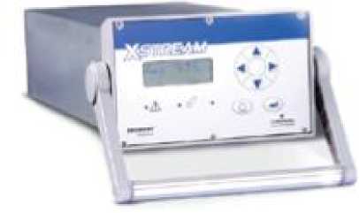
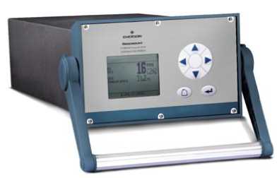
б) модель X-STREAM ХЕ исполнение XEGK
а) модель X-STREAM Х2 исполнение X2GK
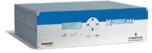
в) модель X-STREAM Х2 исполнение X2GP

г) модель X-STREAM ХЕ исполнение XEGP
д) модель X-STREAM Х2 исполнение X2FD
е) модель X-STREAM ХЕ исполнение XEFD
ж) модель X-STREAM ХЕ исполнения XEXF XDF
Рисунок 1 — Общий вид газоанализаторов (модели и исполнения)
з) модель X-STREAM ХЕ исполнения XEXF XEF
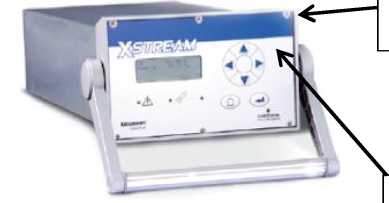
Место пломбирования
Место нанесения знака поверки
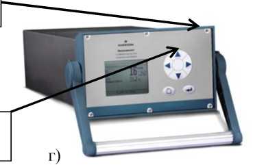
г)
б)
д)
Место пломбирования
е)
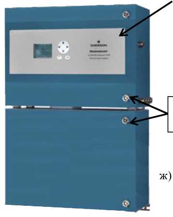
ж)
Место пломбирования
Рисунок 2 — Схема пломбировки от несанкционированного доступа, обозначение места нанесения знака поверки для газоанализаторов X-STREAM модели X-STREAM Х2 (исполнения: а) X2GK; б) X2GP; в) X2FD) и X-STREAM ХЕ (исполнения: г) XEGK; д) XEGP; е) XEFD; ж) XEXF XDF; з) XEXF XEF)
Основные параметры и характеристики газоанализаторов представлены в таблицах 2, 3, 4.
Таблица 2 — Наименования определяемых компонентов, диапазоны измерений, пределы допускаемой основной приведенной погрешности газоанализаторов
|
Определяемый компонент |
Метод анализа |
Диапазон измерений содержания компонента* |
Пределы допускаемой основной приведенной к ВПИ погрешности, % |
|
|
Ацетон |
CH3COCH3 |
ультрафиолетовая фотометрия |
от 0 до 400 млн-1 |
±10 |
|
от 0 до 3 % |
±5 |
|||
|
инфракрасная фотометрия |
от 0 до 500 млн-1 |
±10 |
||
|
от 0 до 3 % |
±5 |
|||
|
Ацетилен |
C2H2 |
инфракрасная фотометрия |
от 0 до 500 млн-1 |
±10 |
|
от 0 до 100 % |
±5 |
|||
|
Аммиак |
NH3 |
инфракрасная фотометрия |
от 0 до 100 млн-1 |
±8 |
|
от 0 до 3000 млн-1 |
±6 |
|||
|
от 0 до 100 % |
±5 |
|||
|
Аргон |
Ar |
по теплопроводности |
от 0 до 50 % |
±5 |
|
от 0 до 100 % |
±5 |
|
Определяемый компонент |
Метод анализа |
Диапазон измерений содержания компонента* |
Пределы допускаемой основной приведенной к ВПИ погрешности, % |
|
|
Двуокись углерода |
CO2 |
инфракрасная фотометрия |
от 0 до 5 млн-1 |
±10 |
|
от 0 до 100 млн-1 |
±8 |
|||
|
от 0 до 1 % |
±5 |
|||
|
от 0 до 10 % |
±5 |
|||
|
от 0 до 100 % |
±3 |
|||
|
Оксид углерода |
CO |
инфракрасная фотометрия |
от 0 до 10 млн-1 |
±10 |
|
от 0 до 500 млн-1 |
±8 |
|||
|
от 0 до 3000 млн-1 |
±6 |
|||
|
от 0 до 1 % |
±5 |
|||
|
от 0 до 10 % |
±5 |
|||
|
от 0 до 100 % |
±3 |
|||
|
Хлор |
Cl2 |
ультрафиолетовая фотометрия |
от 0 до 100 млн-1 |
±15 |
|
от 0 до 100 % |
±5 |
|||
|
Этан |
C2H6 |
инфракрасная фотометрия |
от 0 до 600 млн-1 |
±10 |
|
от 0 до 100 % |
±5 |
|||
|
Этанол |
C2H5OH |
инфракрасная фотометрия |
от 0 до 1000 млн-1 |
±15 |
|
от 0 до 10 % |
±5 |
|||
|
Этилен |
C2H4 |
инфракрасная фотометрия |
от 0 до 400 млн-1 |
±10 |
|
от 0 до 100 % |
±5 |
|||
|
Гелий |
He |
по теплопроводности |
от 0 до 10 % |
±10 |
|
от 0 до 100 % |
±5 |
|||
|
Г ексан |
СбН14 |
инфракрасная фотометрия |
от 0 до 100 млн-1 |
±10 |
|
от 0 до 10 % |
±5 |
|||
|
Водород |
H2 |
по теплопроводности |
от 0 до 1 % |
±5 |
|
от 0 до 10 % |
±5 |
|||
|
от 0 до 50 % |
±5 |
|||
|
от 0 до 100 % |
±3 |
|||
|
Сероводород |
H2S |
ультрафиолетовая фотометрия |
от 0 до 1 % |
±10 |
|
от 0 до 10 % |
±5 |
|||
|
инфракрасная фотометрия |
от 0 до 10 % |
±7 |
||
|
от 0 до 100 % |
±5 |
|||
|
Метан |
CH4 |
инфракрасная фотометрия |
от 0 до 100 млн-1 |
±10 |
|
от 0 до 1000 млн-1 |
±8 |
|||
|
от 0 до 1 % |
±6 |
|||
|
от 0 до 20 % |
±5 |
|||
|
от 0 до 100 % |
±3 |
|
Определяемый компонент |
Метод анализа |
Диапазон измерений содержания компонента* |
Пределы допускаемой основной приведенной к ВПИ погрешности, % |
|
|
Метанол |
CH3OH |
инфракрасная фотометрия |
от 0 до 1000 млн-1 |
±15 |
|
от 0 до 10 % |
±5 |
|||
|
н-Бутан |
C4H10 |
инфракрасная фотометрия |
от 0 до 800 млн-1 |
±10 |
|
от 0 до 100 % |
±3 |
|||
|
Диоксид азота |
NO2 |
ультрафиолетовая фотометрия |
от 0 до 25 млн-1 |
±10 |
|
от 0 до 250 млн-1 |
±8 |
|||
|
от 0 до 1000 млн-1 |
±6 |
|||
|
от 0 до 10 % |
±5 |
|||
|
Оксид азота |
NO |
инфракрасная фотометрия |
от 0 до 100 млн-1 |
±10 |
|
от 0 до 500 млн-1 |
±10 |
|||
|
от 0 до 2500 млн-1 |
±8 |
|||
|
от 0 до 1 % |
±6 |
|||
|
от 0 до 100 % |
±5 |
|||
|
Закись азота |
N2O |
инфракрасная фотометрия |
от 0 до 100 млн-1 |
±10 |
|
от 0 до 100 % |
±5 |
|||
|
Кислород |
O2 |
электрохимический |
от 0 до 5 % |
±5 |
|
от 0 до 25 % |
±5 |
|||
|
парамагнитный |
от 0 до 1 % |
±5 |
||
|
от 0 до 25 % |
±5 |
|||
|
от 0 до 100 % |
±3 |
|||
|
Кислород (следовое) |
O2 |
электрохимический |
от 0 до 10 млн-1 |
±15 |
|
от 0 до 10000 млн-1 |
±10 |
|||
|
Пропан |
C3H8 |
инфракрасная фотометрия |
от 0 до 1000 млн-1 |
±10 |
|
от 0 до 100 % |
±5 |
|||
|
Пропилен |
СзНб |
инфракрасная фотометрия |
от 0 до 400 млн-1 |
±10 |
|
от 0 до 100 % |
±5 |
|||
|
Диоксид серы |
SO2 |
ультрафиолетовая фотометрия |
от 0 до 25 млн-1 |
±10 |
|
от 0 до 500 млн-1 |
±10 |
|||
|
от 0 до 3000 млн-1 |
±6 |
|||
|
от 0 до 1 % |
±5 |
|||
|
инфракрасная фотометрия |
от 0 до 1 % |
±7 |
||
|
от 0 до 100 % |
±5 |
|||
|
Фторид серы |
SF6 |
инфракрасная фотометрия |
от 0 до 20 млн-1 |
±15 |
|
от 0 до 2 % |
±5 |
|||
|
Толуол |
C7H8 |
ультрафиолетовая фотометрия |
от 0 до 300 млн-1 |
±15 |
|
от 0 до 5 % |
±10 |
|||
|
Бензол |
СбНб |
ультрафиолетовая фотометрия |
от 0 до 300 млн-1 |
±15 |
|
от 0 до 5 % |
±10 |
|
Определяемый компонент |
Метод анализа |
Диапазон измерений содержания компонента* |
Пределы допускаемой основной приведенной к ВПИ погрешности, % |
|
|
Винилхлорид |
C2H3CI |
инфракрасная фотометрия |
от 0 до 1000 млн-1 |
±15 |
|
от 0 до 2 % |
±10 |
|||
|
Водяной пар |
H2O |
инфракрасная фотометрия |
от 0 до 1000 млн-1 |
±10 |
|
от 0 до 8 % |
±5 |
|||
|
Водяной пар (следовое) |
H2O |
емкостной |
от 0 до 100 млн-1 |
±15 |
|
от 0 до 3000 млн-1 |
±10 |
|||
|
* Диапазоны измерений и определяемые компоненты определяются при заказе и могут составлять от 1 до 5 для модели X-STREAM ХЕ и от 1 до 4 для модели X-STREAM Х2. При заказе диапазона с верхним значением, отличным от приведенных в таблице 2, выбирают наименьший диапазон измерений, включающий это значение. |
Таблица 3 — Метрологические характеристики газоанализаторов
|
Наименование характеристики |
Метод анализа |
||||||
|
— ультрафиолетовая фотометрия |
— инфракрасная фотометрия |
— электрохимический |
— электрохимический (O2 — следовое) |
— парамагнитный |
— емкостный (H2O — следовое) |
— теплопроводность (TCD) |
|
|
1 |
2 |
3 |
4 |
5 |
6 |
7 |
8 |
|
Предел допускаемого СКО случайной составляющей приведенной к ВПИ погрешности, % |
1 |
||||||
|
Предел допускаемой вариации выходного сигнала, % |
0,5 пределов допускаемой основной приведенной к ВПИ погрешности |
||||||
|
Пределы допускаемой дополнительной приведенной к ВПИ погрешности за счет изменения температуры окружающей среды на каждые 10 °С от нормальной, % |
±1 |
||||||
|
Пределы допускаемой дополнительной приведенной к ВПИ погрешности за счет изменения расхода газа, % |
±0,5 |
±2 |
±1 |
|
1 |
2 |
3 |
4 |
5 |
6 |
7 |
8 |
|
Пределы допускаемой дополнительной приведенной к ВПИ погрешности за счет влияния давления на 1 гПа, %, |
|||||||
|
при постоянной температуре: — без датчика компенсации |
|||||||
|
давления; |
±0,10 |
||||||
|
— с датчиком компенсации |
|||||||
|
давления |
±0,01 |
||||||
|
Нестабильность за 7 сут, % от верхнего предела диапазона измерений: — нуля |
2 |
2 |
|||||
|
-диапазона |
0,5 |
1 |
|||||
|
Время установления показаний (t90), c, не более |
7 |
12 |
80 |
5 |
300 |
30 |
|
|
Время прогрева, мин |
от 15 до 50 |
50 |
Таблица 4 — Технические характеристики
|
Технические характеристики |
Значения для исполнений |
||||
|
XEFD, X2FD |
XEGK, X2GK |
XEGP, X2GP |
XEXF XEF |
XEXF XDF |
|
|
Расход анализируемого газа, л/мин |
от 0,2 до 1,5 |
||||
|
Номинальное напряжение питания: |
|||||
|
— от источника переменного тока, В |
от 100 до 240 |
||||
|
— частота переменного тока, Гц |
50/60 |
||||
|
— от источника постоянного тока, В |
24 (опция) |
||||
|
одноотсечная |
двухотсечная |
||||
|
Габаритные размеры, мм, не более: |
модель |
модель |
|||
|
— длина |
222 |
460 |
411 |
400 |
815 |
|
— ширина |
512 |
130 |
133 |
550 |
550 |
|
— высота |
578 |
220 |
482 |
265 |
265 |
|
Масса, кг, не более |
63 |
12 |
16 |
25 |
45 |
|
Температура окружающей среды, °С |
от -20 до +50 |
от 0 до +50 |
от 0 до +50 |
от — 20 до + 50 |
|
|
Относительная влажность |
|||||
|
окружающей среды |
90 (при +20 °С), |
||||
|
(без конденсации), %, не более |
70 |
(при +40 °С) |
|||
|
Температура окружающей среды при хранении |
|||||
|
и транспортировании, °С |
от -20 до +70 |
||||
|
Средний срок службы, лет |
10 |
||||
|
Степень защиты оболочки по |
|||||
|
ГОСТ 14254 |
1Р66 |
IP20 |
IP20 |
1Р66 |
|
|
Маркировка взрывозащиты |
1ExdII BT4/H2 |
||||
|
X |
Конструктивно прибор выполнен в виде отдельного блока с ЖК дисплеем. Измерения концентрации газов осуществляются с помощью следующих детекторов (за исключением анализатора XS-O2):
— недисперсионного фотометрического NDIR/VIS/UV (аммиак, диоксид азота, оксид азота, гексан, метан, оксид азота, диоксид азота, пропан, диоксид серы, толуол, вода);
— парамагнитного РОг (кислород);
— электрохимического ЕОг (кислород);
— по теплопроводности TCD (аргон, гелий, водород, метан).
Измерение концентрации газа (кислорода) в анализаторе XS-O2 осуществляется при помощи циркониевого детектора (ячейки)/
Наименования модификаций и максимальное количество измерительных каналов газоанализаторов «X-STREAM» приведены в Таблице
На лицевой панели газоанализаторов расположена клавиатура и ЖК дисплей, на который может быть выведена необходимая информация о состоянии прибора и текущее значение концентрации анализируемого газа (за исключением анализатора XS-O2).
Конструкция приборов и программное обеспечение обеспечивают автоматическую градуировку. Также в анализаторах обеспечивается последовательный интерфейс передачи данных RS 485/232C (за исключением анализатора XS-O2). Во всех анализаторах предусмотрен вывод информации в аналоговой форме (4.. .2Р) мА/(Р.. .2Р) мА.
Модель X2GC выполнена в виде основного блока и внешнего источника блока питания.
Индикация показаний, настройка, калибровка и диагностика анализатора XS-O2 может осуществляться следующими методами:
— с помощью коммуникации HART через ручной коммуникатор модели 375;
— при помощи программного обеспечения AMS компании Emerson;

Газоанализатор — это измерительный прибор для определения качественного и количественного состава смесей газов.
Газоанализаторы X-STREAM модели X-STREAM ХЕ и X-STREAM Х2 (далее — газоанализаторы) предназначены для измерения объемной доли различных компонентов в газовых средах в промышленных выбросах, для определения примесей в чистых газах, биогазах и других технологических газах.
Данная стаття носит исключительно информационно-ознакомительный характер и не несет никакого рекламного или коммерческого подтекста.
Принимаем оплату российскими картами, выкупаем и доставляем ваши заказы из магазинов США и Германии. Наша доставка работает в стандартном режиме.
×
Сейчас вы находитесь в городе Москва
Выберите город, в который Вы хотите осуществить доставку


![]()
![]()
Вопрос по товару?
Мы перезвоним!
Основные характеристики
Группа товаров:
Другое автоматизированное оборудование
Оригинальное название:
Emerson Rosemount Analytical X-Stream X2FD-pO2 Gas Analyzer Flameproof Variation
Товар из США
Доставим в Ваш город
Артикул:303782277247
Продавец:
worldwide_commerce
(1680)
Местонахождение:Campbellsville, Kentucky, US
Доставка до склада США
Бесплатно

Товары из магазинов
США и Европы
без наценок!
Отправили
67 000 посылок
с 2008 года!
Знаменитый
каталог eBay
на русском языке!
Доставка курьером
до двери
Почтой или в удобный пункт выдачи!
Похожие товары
Emerson Rosemount Analytical X-Stream X2FD-pO2 Gas Analyzer Flameproof Variation
Emerson Rosemount Analytical X-Stream X2FD-pO2 Gas Analyzer Flameproof Variation – можно купить на shopozz.ru с доставкой
из Campbellsville, Kentucky, US. Все товары из
категории «Другое автоматизированное оборудование» быстро и вовремя доставляются в Россию и страны СНГ.
Полную информацию о доставке можно посмотреть в разделе «Доставка».
На товары категории «Другое автоматизированное оборудование» действует доступная цена,
поэтому Emerson Rosemount Analytical X-Stream X2FD-pO2 Gas Analyzer Flameproof Variation можно
приобрести всего за
721807 руб.
Не можете сделать выбор? Посмотрите другие товары продавца
worldwide_commerce
(1680)
–
«Смотреть все товары».
Возникли вопросы о товаре, условиях оплаты либо доставки?
Закажи обратный
звонок!
Другие бренды категории
В чем наша ценность
Покупки без ограничений
- Доставка в любой город СНГ
- Простой процесс оплаты
- Каталог на русском языке
Доступ к 3 млн. товаров
- Доставка в любой город СНГ
- Простой процесс оплаты
- Каталог на русском языке
Консолидация и сервис
- Доставка в любой город СНГ
- Простой процесс оплаты
- Каталог на русском языке
Покупки в США и Европе — это просто
Вы делаете заказ — мы выкупаем товары и доставляем вам
Склад

$46
Косметика M.A.C.maccosmetics.com

$46
Часы Timexamazon.com

$15
Джинсы levi’sebay.com
К вам домойОтправляем в Россию и
во все страны СНГ
Начать выгодные покупки в зарубежных интернет-магазинах