Использование Geoscan Planner
Предварительная настройка
- Подключите модем КРЛ к USB порту ноутбука.
- Включите бортовое питание БВС.
- Запустите программу MdmDisp.
В правом нижнем углу появится пиктограмма антенны и количество подключенных бортов.

Индикатор работы программы MdmDisp
3.1 При первом подключении необходимо настроить соединение с БВС, запустив программу NetTopology:
- Нажмите на значок Поиск новых устройств.

Значок поиска новых устройств
Программа отобразит список обнаруженных модемов.
Note
Эфир сканируется до тех пор, пока кнопка Поиск новых устройств не будет нажата повторно.
- Выберите появившийся Борт №xxx и нажмите на значок Добавить устройство.

Значок добавления устройства
Программа сохраняет список добавленных устройств.
При проведении повторных полетов достаточно запустить MdmDisp и убедиться, что подключение выполнено успешно.
Если БВС не обнаружен, запустить поиск бортовых модемов, нажав на значок MdmDisp правой кнопкой мыши и выбрав Переподключить.

Контекстное меню MdmDisp
- Запустите программу Geoscan Planner.
- В окне ввода логина и пароля введите свой логин и пароль пользователя продукта.
- Во вкладке Полет выберите Подключить БВС — Поиск….*

Подключение БВС
- Выбрать тип подключения MdmDisp. Задать IP-адрес localhost. В списке Борт установить для БВС — Порт 2.

Окно подключения БВС
Note
Параметры достаточно установить один раз. При последующих подключениях БВС воспользуйтесь кнопкой Подключить БВС панели инструментов. Приемник автоматически определит координаты и отобразит местоположение БВС на карте. В окне программы появятся панель телеметрии (слева) и панель приборов (справа).

Подключение БВС
Проектирование полетного задания
- Создайте Новый проект.

Создание нового проекта
Укажите имя проекта, параметры съемки, модель БВС и фотоаппарата.

Создание нового проекта полетного задания
Площадная аэрофотосъемка
Площадная аэрофотосъемка – съемка полигонов. Полигон – это область, ограниченная многоугольником. Оператор задает вершины многоугольника (не менее 3), а программа автоматически рассчитывает маршрут обхода.
- Нажмите на значок Создать площадную аэрофотосъемку панели инструментов.

Создание площадной аэрофотосъемки
- Щелчками кнопки мыши задайте на карте угловые точки исследуемого участка местности. Программа автоматически рассчитает маршрут обхода полигона.

Пример построения площадной аэрофотосъемки
Добавление и удаление вершин полигона
В готовый полигон можно добавлять вершины.
- С зажатой левой кнопкой мыши переместите среднюю точку стороны полигона.

Добавление вершины
Вершина будет создана автоматически.
В плавающем окне рядом с вершиной отобразятся ее координаты.

Результат добавления вершины
Для удаления вершины:
- нажмите на вершину правой кнопкой мыши;
- в контекстном меню выберите Удалить вершину.

Удаление вершины
Изменение направления линий облета
Необходимость оптимизировать полигон «по направлению» возникает, например, если на месте проведения работ сила и направление ветра неблагоприятны (сильный ветер вдоль линий облета полигона).
Для изменения типа оптимизации щелкните правой кнопкой мыши на полигоне и выберите в контекстном меню вариант Оптимизация «направление».

Оптимизация по направлению
Одна из вершин полигона будет подсвечена, на ней появится бегунок для задания направления.

Корректировка направления облета
Результатом будет новый маршрут облета полигона по заданному направлению.

Новый маршрут облета
Изменение точки входа
Если необходимо сменить точку входа в полигон, то выполните следующие действия:
- Выделите полигон.

Выделенный полигон
- Правой кнопкой мыши выделите точку, в которой нужно осуществить вход.
- В появившемся контекстном меню выберите Начать здесь.

Изменение точки входа в полигон
У выбранной точки входа появится флажок 
Линейная аэрофотосъемка
Команда Создать линейную аэрофотосъемку служит для облета линейных протяженных объектов, таких как: реки, дороги, нефтепроводы и т.п..
- Нажмите на значок Создать линейную аэрофотосъемку панели инструментов.

Создание области линейной аэрофотосъемки
- Однократными щелчками задайте маршрут обхода протяженного объекта по точкам разворотов. Программа автоматически построит линии облета.

Пример линейной аэрофотосъемки
Полет по точкам
Команда Создать полет по точкам может использоваться для обследования территорий или облета высотных объектов.
- Нажмите на значок Создать полет по точкам на панели инструментов.

- Однократными щелчками задайте маршрут полета по точкам.

Note
По умолчанию фотографирование во время полета по точкам не осуществляется. При необходимости настройте Режим фотографирования в панели Свойства.
- Щелчком правой кнопки мыши по точке вы можете задать время «зависания» БВС. Выберите Задать задержку в точке и укажите время в секундах.
Точка ожидания
Команда Создать точку ожидания служит для удержания БВС в точке на высоте заданное время.
- Нажмите на значок Создать точку ожидания на панели инструментов.

- Щелчком мыши на карте задайте точку, в которой должно осуществляться ожидание.
В экспертном режиме (см. полное руководство Geoscan Planner) можно изменить свойства: задать высоту точки ожидания, длительность ожидания, направление движения и активировать функции измерения ветра и бесконечного ожидания.

Планер будет на заданной высоте «удерживать» точку в течение указанного времени (по умолчанию 300 секунд), после чего отправится по запланированному маршруту.
При активации варианта Измерение ветра длительность автоматически выставляется в значение 0. При этом точка ожидания окрасится в желтый цвет. Самолет выполняет полный оборот с постоянным измерением ветра.

Функция бесконечного ожидания служит для постоянного удержания точки (пока не сработает отказ по низкому заряду АКБ, приводящий к автоматическому возврату). При этом цвет точки ожидания сменяется на темно-синий.

Attention!
Рекомендуется устанавливать точку ожидания с измерением ветра перед каждым полетным элементом на высоте полетного элемента. Автопилот, учитывая измеренные данные о ветре, будет плавнее идти по маршруту.
Attention!
Комплексы Геоскан не являются сертифицированными приборами измерения ветра, поэтому не могут быть использованы в качестве надежных источников данных о состоянии окружающей среды.
Панорамная съемка
Команда Создать панорамную съемку служит для съемки серии фотографий с последующим программным преобразованием в единую панораму.
- Нажмите на значок Создать панорамную съемку на панели инструментов.

По умолчанию выполняется съемка в полный оборот по азимуту и в пределах от 0 до 80 по наклону. При необходимости пользователь может изменить параметры панорамной съемки во вкладке Свойства режима эксперта (см. полное руководство по Geoscan Planner).
Точка посадки
Команда Создать точку посадки служит для указания места приземления БВС.
При отсутствии заданной точки посадки БВС по окончанию полетного задания вернется в точку старта.
- Нажмите на значок Создать точку посадки на панели инструментов.

- Щелчком мыши укажите точку приземления БВС.
Предстартовая подготовка
- Запустите Мастер предстартовой подготовки.

Запуск мастера предстартовой подготовки
Следуйте указаниям мастера предстартовой подготовки (большинство проверок выполняются автоматически).
Задайте радиус автоматического отцепа парашюта и время автономного полета (время, в течение которого осуществляется полет независимо от наличия связи между НСУ и БВС).
После прохождения предстартовой подготовки установите БВС на пусковую установку.
Полет
- Нажмите на значок Старт.

Значок старта
Убедитесь, что все ничего не мешает вращению лопастей и подтвердите запуск двигателей.

Подтверждение запуска двигателей
Автопилот проверит работу двигателей. На экране НСУ появится окно подтверждения взлета.

Подтверждение взлета
БВС осуществит взлет.
Note
БВС выполняет полет в автоматическом режиме, однако это не освобождает оператора от обязанностей по наблюдению за процессом полета. Постоянное наличие связи по радиолинии не является необходимым для успешного выполнения задания.
Возврат
Команда Возврат отправляет борт к стартовой точке. Достигнув положения напротив стартовой точки на высоте, БВС выполняет посадку.
- Нажмите на значок Возврат.

Значок возврата БВС
Посадка
Команда Посадка служит для выполнения снижения и немедленной посадки.
- Нажмите на значок Посадка.

Значок посадки БВС
Attention!
Автоматическое замедление при посадке срабатывает по барометрической высоте. Не рекомендуется указывать точку посадки в месте, сильно отличающемся по рельефу от места взлета.
Полет по требованию
Команда Полет по требованию позволяет отправить БВС на указанную точку на карте (с указанием высоты).
По достижении указанной точки БВС начнет удержание данной точки, пока оператор не вмешается в выполнение полетного задания, либо пока не сработает автоматический возврат по отсечке батареи.
- Нажмите на значок Полет по требованию.

Значок полета по требованию
- Укажите точку на карте и задайте высоту.

Задание высоты полета по требованию
По достижении точки БВС будет удерживать указанные координаты.

Пример полета по требованию
Дистанционное управление
Активация режима дистанционного управления возможна после прохождения предстартовой подготовки и взлета.
- Нажмите на Значок Дистанционное управление.

Значок дистанционного управления
Attention!
Если во время активации ручного режима БВС выполнял задание по площадной или линейной АФС, то после отключения ручного режима выполнение задания будет продолжено.
Будет осуществлен переход в ручной режим управления.
По умолчанию дистанционное управление осуществляется через Управление скоростями. В таком случае выполняется векторный контроль отклонений кнопками в окне
дистанционного управления или клавиш:

Окно дистанционного управления
- W – полет прямо по курсу (вперед)
- A — изменить направление полета в левую сторону (влево)
- S — полет в обратную сторону относительно курса (назад)
- D — изменить направление полета в правую сторону (вправо)
- T — набор высоты (вверх)
- G — снижение (вниз)
- [ – изменить курс в левую сторону (вращение влево)
- ] – изменить в правую сторону (вращение вправо)

- Manuals
- Brands
- Geoscan Manuals
- Drones
- 401
- Operating manual
-
Contents
-
Table of Contents
-
Bookmarks
Quick Links
Related Manuals for Geoscan 401
Summary of Contents for Geoscan 401
-
Page 2: Table Of Contents
……… 21 7 Geoscan Planner Preset .
-
Page 3
7.14 Semi-automatic control ……..37 8 Launch 9 UAV disassembly… -
Page 4: General Information
CHAPTER GENERAL INFORMATION Geoscan 401 – multifunctional complex, that included multirotor unmanned aerial vehicle (UAV) and ground control system (GCS). 1.1 Kit • Geoscan 401 unmanned aerial vehicle (UAV) • UAV’s transport container • Payload: * – customized Sony А6000 camera;…
-
Page 5: Technical Parameters
Visually inspect UAV for a damage after each flight. If a propellers are damaged, you can replace it yourself using spare parts and tools from the kit. If structural damage to the airframe or systems is detected, contact Geoscan support. Chapter 1. General information…
-
Page 6: Storage
After 80 flights it is recommended to send your UAV to the manufacturer for inspection and maintenance. 1.4 Storage Geoscan 401 complex (without battery) are recommended to be stored in a transport containers in dry rooms at a temperature of 5 to 25 °C and relative humidity not more than 80% without condensation.
-
Page 7: Safety Rules
• UAV launch and maintainence can be held only by persons trained according to the “Plan of the- oretical and practical training of the operator to control the unmanned complex GEOSCAN 401”; • before the flight it is necessary to inspect the flight area and make sure that the planned flight path passes not less than 100 m above the terrain and high-rise objects (mountains, towers, pipes, transmission towers, etc.);…
-
Page 8: Uav
CHAPTER THREE 3.1 Parts 3.2 Assembly 1) Take the landing gears base part and landing gears from the UAV’s transport container. 2) Put landing gears in the landing gears base part tubes. 3) Tighten connecting nuts on landing gears by hands. 4) Fix nuts position by elastic fixators.
-
Page 9
Fig. 1: Installation and fixation of the landing gears 5) Take the quadcopter from the UAV’s transport container. 6) Remove a protective transport elements. 7) Take the quadcopter’s frame arms out to the sides. Fig. 2: Quadcopter assemblyMove frame arms nuts to the quadcopter’s frame central part and tighten it. Chapter 3.
-
Page 10
Fig. 3: Quardcopter’s nuts moving Attention: Make sure that the nuts are covered frame pins. 9) Put the quadcopter on landing gears base part. • Frame loops must be connected with landing gear’s loops. • Take the servo cradle and position it under the quadcopter’s frame. The frame loops must be connected with servo cradle’s loops. -
Page 11
Fig. 5: Connection of the parts Attention: Make sure that, the rods are fully puted (Rod’s rings must be puted into red seals). 10) Install propellers on the motors. The color markings on the motors and propellers must be the same. -
Page 12
Attention: Before each start make sure that all propellers are not damaged. Do not use worn, cracked or damaged propellers. 11) Put payload’s connection cable (if payload connects with UAV) in quardcopter’s slot. Fig. 7: Connection of the payload cable 12) Screw CRL antenna in quadcopter’s arm pin. -
Page 13
13) Eject payload’s memory cards, format and insert them back. * * — Depends on equpment Fig. 9: Instaling memory card in UAV’s slot (kit with GNSS receiver). 14) Install the battery in battery slot until it stops (Battery pins must be on the left side looking forward). Fig. -
Page 14: Ground Control System
CHAPTER FOUR GROUND CONTROL SYSTEM 4.1 Kit 4.2 Assembly and set up 1) Eject the GCS table from the UAV’s transport container. 2) Place the table on a flat work surface. 3) Undo textile clasp and eject a laptop. 4) Assemble parts of the CRL pole together. 5) Eject the GCS modem and CRL antenna from UAV’s transport container.
-
Page 15: Set Up The Camera
CHAPTER FIVE SET UP THE CAMERA 5.1 Set up the Sony DSC-RX1 camera Read the camera’s full operating instructions to know about main control elements before make settings. • Set mode dial in S (Shutter Priority) position. • Use control dial to set exposition 1/800. •…
-
Page 16
Fig. 3: MF Assist is off and Focus Magnif. Time • In tab 3 set MOVIE Button — Movie Mode Only. Fig. 4: Set mode movie mode only for MOVIE button • In setup menu set Power Saving Start Time — 30 min (tab 2). Fig. -
Page 17: Set Up The Sony A6000 Camera
Fig. 6: File number reset • Press Fn (Function) button to set these settings: Drive Mode Single Shooting White Balance Auto AWB Select ISO — Auto and set: ISO Minimum ISO Maximum 1600 Keep default parameters for other camera settings. Format SD card 1) Select MENU [SD Card]…
-
Page 18
• Set the mode dial to S (Shutter Priority). Use the control wheel to set the following parameters: Exposition 1/800 Auto • In still shooting menu (tab 2) set Focus Mode — Manual focus. Fig. 7: Focus Mode • In custom settings menu (tab 1) disable Automatic preview. -
Page 19
• In custom settings menu (tab 6) set the MOVIE button — Video mode only. Fig. 10: Set “Video Mode Only” • In setup menu (tab 2) set Start time energy saving — 30 min. Fig. 11: Set the time to start energy saving •… -
Page 20: Offsets Coordinates
5.3 Offsets coordinates The antenna of the geodetic receiver is located inside the UAV. The phase center is offset from the center point of the camera lens. The amount of offset should be taken, when you generate ortophotomaps and 3D models. Fig.
-
Page 21: Charger And Battery
CHAPTER CHARGER AND BATTERY Table 1: Parameters of the battery Guaranteed number of charge-discharge cycles Upper charge voltage 42 V Normal voltage ~37 V Lower discharge voltage 33 V Charging current <24 А Number of cells Capacity 16 000 mAh Shelf life 1 year 6.1 Safety requirements…
-
Page 22: Preset Of The Battery Charger
6.2 Preset of the battery charger Follow these steps to open the settings menu: • In PROGRAM SELECT menu (main screen) press the Batt type/Stop button repeatedly, until charger’s display shows Settings menu; • Confirm by pressing the button Start/Enter; •…
-
Page 23: How To Connect The Battery To The Charger
6.3 How to connect the battery to the charger • Connect balance pin. • Connect + terminal (red cable). • Connect — terminal (black cable). Attention: Make sure that the engine is run, when you charge the battery from car battery. A car battery is completely discharged, if you don’t check it.
-
Page 24: Lithium Polymer (Lipo) Battery Recommendations On The Use
Table 3: Key battery’s state values Type of bat- Charged Half Charge level is near Dis- Power is lose, Battery is tery charge zero charged broken 10S 16Ah 42,0 V 37,0 V 35,0 V 33,0 V >25,0 V The battery discharge speed is directly dependent with speed of engines. The UAV use trajectory and weather’s data to automatically set a optimal speed level.
-
Page 25: Geoscan Planner
CHAPTER SEVEN GEOSCAN PLANNER 7.1 Preset 1) Connect CRL modem with the notebook. 2) Turn UAV power. 3) Run application MdmDisp. The antenna icon and the number of connected UAV’s on the screen’s lower right corner are displayed. Fig. 1: MdmDisp program indicator 3.1 At the first time you need to configure connection with UAV.
-
Page 26
You can reconnect the CRL modem by clicking Reconnect in context menu, if UAV is not detected. Fig. 4: MdmDisp сontext menu 4) Run the Geoscan Planner program. 5) Enter your login and password. 6) In context menu Flight select Connect to the UAV – Search… for a searching UAV’s. -
Page 27: Creating A Flight Task
UAV. The receiver will automatically detect the coordinates and display the UAV location on the map. The telemetry panel (left) and the instrument panel (right) will shown in program window. Fig. 7: Connect to the UAV 7.2 Creating a flight task 1) Create New project. Chapter 7. Geoscan Planner…
-
Page 28
Fig. 8: New project creation 2) Set a project name, shooting parameters, UAV and camera. Fig. 9: Project parameters 7.2. Creating a flight task… -
Page 29: Areal Surveying
1) Click on Create areal surveying button on the toolbar. Fig. 10: Areal surveying creation 2) By single mouse clicking specify the angular points of the research site. The program automatically calculates the route for bypassing the polygon. Fig. 11: Areal surveying example Chapter 7. Geoscan Planner…
-
Page 30
7.3.1 Adding and removing polygon vertices. You can add vertices to the completed polygon. 1) Hold the left mouse button and move the middle point of the polygon side. Fig. 12: Adding the vertex The vertex will be created automatically. In a floating window near the vertex will display its coordinates. Fig. -
Page 31
1) Right-click on the polygon area. 2) Select Optimization by “direction”. Fig. 15: Optimization by direction One of the vertices of the polygon will be highlighted and a rotation marker will appear on it to set the direction. Chapter 7. Geoscan Planner… -
Page 32
Fig. 16: Adjusting the direction of flight As a Result, there will be a new route to fly around the area in the specified direction. Fig. 17: New flight route 7.3.3 Change start point To change the polygon entry point, follow these steps: 1) Select polygon 7.3. -
Page 33
2) Right-click to select the point where you want to start circling the area. 3) In menu select Make start point here. Fig. 19: Change the polygon entry point A marker appears at the selected entry point. Chapter 7. Geoscan Planner… -
Page 34: Linear Surveying
7.4 Linear surveying Linear aerial photography is performed in order to survey linear extended objects, such as: rivers, roads, power lines, oil pipelines. 1) Click Create linear surveying button on the toolbar. Fig. 20: Linear surveying creation 2) Single-click to specify the route of traversing the extended object by turning points. The program will automatically draw lines of flight.
-
Page 35: Flight By Points
Set hover at point and specify the time in seconds. 7.6 Waiting point Waiting point serves to hold the indicated point at the specified altitude during the specified time interval. 1) Click Create waiting point button on the toolbar. Chapter 7. Geoscan Planner…
-
Page 36: Panoramic Survey
The UAV will hold the point for the specified time at the specified height, and then go along the planned route. In expert mode (see full Geoscan Planner instructions) properties may be changed: setting an altitude of the waiting point, the waiting time and activation of the wind measurement function.
-
Page 37: Landing Point
Shooting is carried out in full rotation in azimuth and in the range from 0 to 80 in tilt by default. If it needs, you can change the parameters of the panoramic shooting in the Properties tab of expert mode (see full Geoscan Planner instructions). 7.8 Landing point Use Create landing point command to set landing point different from start position.
-
Page 38: Flight
Attention: The return height must be must ensure that there are no barriers on the flight route. 7.10 Flight 1) Click on Start button. Fig. 29: Start button Make sure that nothing prevents the rotation of the propellers and confirm the engines start. Fig.
-
Page 39: Land
1) Click Guided flight button. Fig. 34: Guided flight button 2) Specify a point on the map and set the height. Fig. 35: Set the height of the guided flight Chapter 7. Geoscan Planner…
-
Page 40
The UAV will start holding the indicated point, when the point is reached. Fig. 36: Guided flight example 7.14 Semi-automatic control You can activate manual control mode after pre-launch preparation and take off. 1) Click Semi-automatic control button. Fig. 37: Semi-automatic control button Attention: Flight mission is paused when manual control mode is on. -
Page 41
Remove the lens cap. * — if the camera is in the kitOpen a flight task in Geoscan Planner. Launch start preparing wizard. Make sure the preparation is successfully. 9) Click on the Start icon in the Geoscan Planner.
-
Page 42
CHAPTER NINE UAV DISASSEMBLY 1) Unfasten textile clasp and take out the battery. 2) Unscrew propellers. 3) Disconnect payload cable. * 4) Unscrew CRL antenna. 5) Take out mounting rods and place servo cradle in transport container. 6) Unscrew quadcopter’s nuts and move them closer to motors. Nuts should not interfere to fold the quadcopter’s arms.
Поиск и добыча углеводородов
Используемое исследовательское оборудование
![]()
![]()
-
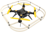
Беспилотный летательный аппарат Геоскан 401
Общество с ограниченной ответственностью «Геоскан»
Связанная услуга
Геодезические исследования с помощью аэрофотосъемки и магниторазведки
Поиск и добыча углеводородов
Стоимость: По запросу
![]()
Геоскан 401 позволяет выполнять съемку как по заданному полетному заданию с заранее рассчитанной траекторией движения, так и путем интерактивного указания контрольных путевых точек в наземной станции управления. Причем переход из одного режима в другой возможен непосредственно во время полета.
Использование современных композитных материалов в конструкции рамы и корпуса, а также ряда уникальных конструктивных решений позволяют Геоскан 401 находиться в воздухе до 60 минут и нести при этом полезную нагрузку до 1 кг.
Программное обеспечение наземной станции обладает простым и понятным пользовательским интерфейсом и позволяет подготовить полетное задание любой сложности. Полет Геоскан 401 выполняет по заданному полетному заданию в полностью автоматическом режиме. Вертикальный взлет и посадка позволяют осуществлять запуск аппарата даже в ограниченном пространстве. При падении уровня заряда батарей или при потери связи с наземной станцией управления летательный аппарат сам вернется к месту запуска и совершит мягкую посадку.
Камера устанавливается на гиростабилизированный подвес, позволяющий стабилизировать положение камеры в пространстве.
Геоскан 401 позволяет нести различные виды полезных нагрузок массой до 2 кг. Конструкция крепления полезной нагрузки и универсальный интерфейс подключения позволяет оперативно выполнять замену нагрузок.
Дополнительная полезная нагрузка:
- Гиростабилизированная оптико-электронная система с FullHD видеокамерой
- Гиростабилизированная оптико-электронная система с тепловизором
- Цифровая фотокамера Sony DSС-RX1 (24 Мпикс, объектив 35 мм, полноразмерная матрица, центральный затвор), модернизированная
- Цифровая фотокамера Sony Alpha A5000 с объективом 20 мм.
- Мультиспектральная фотокамера (на базе Sony A5000)
Дополнительное оборудование:
- Дополнительный коптер Геоскан 401 Видео (коптер, электроника, бортовой цифровой передатчик для передачи видео и тепловизионного изображения, бортовой блок связи управление/телеметрия, защитный контейнер IP67, ЗИП, без ПН)
- Модификация «Арктика» (расширение температурного диапазона от -40 до +20 )
Дополнительное программное обеспечение:
- PhotoScan Professional
- ГИС Спутник
- ГИС Спутник Агро
Geoscan 401: Available Instructions
Note for Owners:
Guidesimo.com webproject is not a service center of Geoscan trademark and does not carries out works for diagnosis and repair of faulty Geoscan 401 equipment. For quality services, please contact an official service center of Geoscan company. On our website you can read and download documentation for your Geoscan 401 device for free and familiarize yourself with the technical specifications of device.
-
Udirc U818A WIFI
2Name of Parts1. DroneWhite Blade BBlack Blade APicture 1Black Blade BWhite Blade ALED LightPicture 22. TransmitterPower IndicatorLightMobile PhoneScreenLens hoodThrottle/Rudder StickForward/Backward/Left/RightFlying StickForward/Backward TrimLeft/RightFlying TrimFlipPower SwitchLeft/RightRudder TrimHeadless ModeHigh/LowSpeed Mode LCDFlip IconHeadless Mode IconHigh/Low Speed IconPower OnDirectionU …
U818A WIFI Drones, 13
-
Wingsland Minivet
Product manual 1, Introduction Support and Service Thanks for your choice for Minivet multi-axis aircraft, in order to make it convenient and correct for you to use our product, please read the manual carefully. If you face some difficulties when using products, please contact our distributor or Wingsland Service Center by email or telephone. Wingsland service center: Email address: [email protected] …
Minivet Remote Control, 16
-
WLtoys Q222K
CONTENTS OF THE BOX:• 1 x Quadcopter• 1 x 2.4 GHz remote (6x AA-batteries not included)• 1 x 3.7V 730 mAh Li-po battery• 4 x Spare propeller• 1 x Charger• 1 x Manual• 4 x prop guardsSPECIFICATIONS:• 2.4GHz Assembled quadcopter drone Ready-to-fly• 6-axis Gyroscope• 4 main engines• 1 Li-po Battery 3.7V 730mAh• Height: 58 mm• Length: 375 mm• Width: 136 mm• Weight: 900 gS …
Q222K Drones, 10
-
tbs electronics XRACER
TBS XRACER Micro FPV Racer Revision 2016-10-30 Ready-to-fly micro fpv racer It’s a parrot frame, that we build up with BetaFlight, Spektrum R/C receiver and a TBS UNIFY PRO VTX. Aimed at indoor office/warehouse race flying, or people getting started with carpark racing and other shenanigans. Key features ● Ready-to-fly 120-size FPV racer ● Brushed motors, 56mm Props ● 32-bit Brushed Cle …
XRACER Drones, 38
-
DROCON Cyclone
Fuselage Length:310.5mmOverall height: 60mm Main Rotor Diameter: 138mmGross Weight: about 110gBattery: Li-polymer 3.7V 550 mAh Charging Time: about 90 minutesIntroduction The Quad-rotor design ensures a more stable and powerful performance . The newly-designed structure makes assembly and maintenance much easier.Product/spare parts included in this packagingManualDescription QTY (pc) Descr …
Cyclone Drones, 31
-
dji Phantom 2 Vision +
Place the Phantom on its head (make sure battery is removed) Remove jack plug out of the camera Pull the frame careful out of the rubber holders (Careful: there is a wire connected to the camera) Manual DJI Phantom 2 Vision Dronexpert Gimbal …
Phantom 2 Vision + Camera Accessories, 14
-
SWELLPRO SPLASH DRONE
Splash DroneSplash Drone Splash Drone Splash Drone Splash DroneRemote Controller Safety GuideV1. 0PRO010301 19020405060708091011 121314151617182021220203040506070809101112M2USBA112V12VA05VGNDIMUM1GPSPOWER LEDIO CHANNELS2. 4GHz RECEIVER01 02 03 04www. swellpro. coma. Check the all aircraft parts are in good conditionb. Ensure aircraft and remote controller battery are fullc. Before flight, please c …
SPLASH DRONE Drones, 2
-
Midoceanbrands MO9379
USER MANUAL (2014/53/EU art. 10-8) (a) Frequency Range; 2402-2480 MHz (b) Maximum radio-frequency power; 100mW (EIRP) (2014/53/EU art. 10-9 Simplified Declaration of Conformity) Hereby, MOB, declares that item MO9379 complies with the essential requirements and other relevant conditions of directive 2014/53/EU. The full text of the EU declaration of conformity is available at the fo …
MO9379 Drones, 55
Popular Drones User Guides:
Categories of Geoscan Devices:
- Drones
Содержание
- Внешний вид
- Варианты комплектации
- Лётные характеристики
- Режимы и функциональность
- Сфера применения
- Моторы и аккумулятор
- Камера
- Аппаратура управления
- Комплектация
- Цена
- Характеристики
- Видео
Здравствуйте, наш сегодняшний обзор мы посвятим квадрокоптеру Геоскан 401, выпускаемому группой компаний Геоскан (Санкт-Петербург). Этот производитель специализируется на разработке и выпуске беспилотных комплексов, ориентированных на проведение профессиональных аэрофотосъемок. Помимо этого, ГК Геоскан разрабатывает программное обеспечение для обработки и визуализации полученных данных.
Внешний вид
Стоит пользователю открыть транспортный кейс, как у него сразу появляется ощущение серьезности представшего перед его глазами изделия. Все (даже сам кейс) выглядит солидно и имеет высокий запас прочности. Посадочные ноги Геоскан 401 легко складываются и имеют специальную стыковочную площадку, на которой устанавливается тело летательного аппарата. В основу последнего заложена двухэтажная карбоновая рама, на первом этаже которой размещается аккумуляторная батарея, а на втором – вся электронная начинка квадрокоптера. К раме крепятся складные лучи, заканчивающиеся бесколлекторными электродвигателями. Воздушные винты очень крупные (порядка 17-ти дюймов в диаметре) и также выполнены из карбона.
Крепления специальной конструкции позволяют быстро менять навесное оборудование. Этому способствует и универсальный разъем для его подключения.

Варианты комплектации
Квадрокоптер выпускается в трех вариантах, отличающихся навесным оборудованием.
На базовый вариант дрона устанавливается модернизированная фотокамера Sony A5000, которая может быть заменена как разработанной на ее базе специальной мультиспектральной фотокамерой, так и цифровой камерой Sony DSC-RX1. Возможности летательного аппарата могут быть расширены за счет установки блока спутниковой навигации.

Геоскан 401 Геодезия оснащается модернизированной фотокамерой Sony DSC-RX1. Допускается ее замена на фотокамеру Sony A5000 или камеру, работающую в инфракрасном диапазоне. Этот вариант комплектации также позволяет установку блока спутниковой навигации.

Вариант Геоскан 401 Видео предназначен для ведения воздушной съёмки в режиме реального времени. На этот квадрокоптер устанавливается Full HD видеокамера или тепловизор. При этом дрон получил цифровой канал связи, по которому на монитор оператора передается изображение оптического или инфракрасного спектра.

Все три варианта доступны в исполнении Арктика, имеющем расширенный температурный диапазон применения (от -40 до +40 градусов Цельсия).
Лётные характеристики
Геоскан 401 имеет немалые габариты и вес, что позволяет ему эффективно противодействовать ветру. Его силовая часть разгоняет дрон до 50 км/ч. Практический потолок доходит до 500 м, а дальность – до 10 км. Заряда батареи хватает на 60 минут непрерывного полета в крейсерском режиме. За это время квадрокоптер способен пройти 24 км.
Взлет, посадка и сам полет проходят под управлением автопилота. Маршрут задает оператор с помощью специального мастера предполетной подготовки GeoScan Planner. Сенсоры представлены акселерометром, гироскопом, магнитометром, бародатчиком и датчиком скорости. Этот набор гарантирует летательному аппарату высокую стабильность полета и мягкое приземление. От потери это дорогостоящее изделие предохраняет встроенный радиомаяк. Для более точной привязки к местности может быть задействована система спутниковой навигации.
Модификация Геоскан 401 Видео позволяет оператору управлять подвесом и получать живое видео. Для этих целей аппаратура управления дополняется специальным джойстиком и монитором.
Режимы и функциональность
- Система стабилизации на базе гироскопа, акселерометра и бародатчика;
- Встроенные магнитометр;
- Взлет и посадка в автоматическом режиме;
- Функция экстренной посадки в автоматическом режиме;
- Встроенная система GPS (опция);
- Функция автоматического облета заданных объектов;
- Функция настройки автоматического режима съемки;
- Фиксация координат центров фотографирования;
- Режим круговой съемки;
- Возможность работы в сложных городских условиях;
- Создание 3D моделей местности и объектов;
- Создание виртуальных туров по объектам недвижимости;
- Автопилот по проложенному маршруту;
- Передача изображения в режиме реального времени (опция).


Сфера применения
- Геодезия;
- Строительство;
- Нефте — газовый сектор;
- Лесное и водное хозяйство;
- Экология;
- Охрана природных ресурсов.
Моторы и аккумулятор
Винтомоторная группа представлена бесколлекторными электродвигателями и семнадцатидюймовыми карбоновыми винтами. Тяги, создаваемой ВМГ, вполне хватает для обеспечения максимального взлетного веса квадрокоптера, превышающего 9 кг.


Трехбаночная АКБ собственной сборки имеет емкость 10 Ач и токоотдачу 5C (50 А). Весит батарея порядка 700 г.
Камера
Производитель предлагает три вида полетных камер:
- Модель Sony DSC-RX1 является полнокадровым фотоаппаратом с сенсором Exmor CMOS на 24,7 Мп, графическим процессором BIONZ и объективом Carl Zeiss Sonnar T с фиксированным фокусным расстоянием 35 мм. Максимальное разрешение в режиме фото составляет 6000×4000 точек. Максимальная частота кадров при съемке HD видео равна 60 fps (при разрешении 1920×1080). Данная модель имеет размеры 113x65x69 мм и вес 482 г.
- Фотоаппарат Sony Alpha A5000 представляет собой бюджетную модель с матрицей Exmor CMOS, процессором BIONZ X и разрешением 20,4 Мп. Камера комплектуется объективом Sony 16-50мм f/3,5-5,6 с оптическим стабилизатором изображения. Имеет возможность снимать HD видео с разрешением 1920×1080 при 60 fps. Габариты A5000 равны 110x63x36 мм, а вес не превышает 269 г.
ИК фотоаппарат на базе Sony Alpha A5000 имеет параметры, аналогичные A5000, но работает в волновом диапазоне 400-1000 нм.
- Особо выделим вариант Геоскан 401 Видео. Его спектр навесного оборудования дополнен двумя видами гиростабилизированных двухосевых платформ: тепловизионной и оснащенной видеокамерой формата Full HD.
Первая из них предназначена для тепловизионного обследования обширных территорий и объектов инфраструктуры. Она имеет тепловизор с объективом 19 мм, разрешением 640×480 и встроенным блоком сжатия изображения.
На второй платформе устанавливается цветная видеокамера 1080p, снимающая с частотой кадров 25 fps. Она имеет десятикратный зум и встроенный блок сжатия.
В ПО комплекса входит приложение Agisoft PhotoScan Pro, позволяющее в кратчайшие сроки проводить обработку полученных материалов. По результатам съемки можно строить 3D модели объекта или местности, создавать рекламные ролики или виртуальные туры.
Аппаратура управления
Аппаратура управления представляет собой наземную станцию, в которую входит ноутбук с установленными на нем приложениями GeoScan Planner 2.0 и Agisoft PhotoScan Pro, радиомодем для связи с БПЛА и зарядная станция. Для работы в тяжелых условиях предлагается ноутбук в защищенном исполнении.
В состав наземной станции модификации Геоскан 401 Видео дополнительно включены цифровой широкополосный видеоприемник, монитор для воспроизведения изображения в реальном масштабе времени и джойстик для управления бортовой камерой.
Все оборудование наземной станции помещается в отдельный транспортный кейс.

Комплектация
- БПЛА;
- Камера;
- Подвес;
- Наземная станция управления;
- Зарядное устройство;
- Комплект ЗИП;
- Два транспортных кейса;
- Обучающий курс.
Цена
Базовая версия квадрокоптера Геоскан 401 обойдется покупателю в 1,45 млн. рублей.
Характеристики
- Максимальный взлетный вес: 9,3 кг;
- Максимальный вес полезной нагрузки: 2,5 кг;
- Полные габариты: 1500x1500x430 мм;
- Транспортные габариты: 700x250x200 мм;
- Максимальная скорость: 50 км/ч;
- Максимальная дальность полёта: 10 км;
- Продолжительность полета: до 1 ч;
- Допустимая скорость ветра: до 10 м/с;
- Безопасная высота полета: 10-500 м;
- Размер площадки для приземления: 5×5 м;
- Время подготовки к полету: 5 минут;
- Тип двигателей: электрические бесколлекторные;
- Допустимый температурный диапазон (град. Цельсия): от -20 до +40.
Рейтинг квадрокоптера
- Цена- качество
- Лётные характеристики
- Комплектация
- Дизайн
- Камера
- FPV
- Надёжность
- Функциональность
Достоинства и недостатки
Геоскан 401 эксплуатируется уже несколько лет и получает неплохие отзывы промышленников. Данная модель квадрокоптера способна выполнять задачи геологической, картографической и геодезической разведки местности, вести воздушное патрулирование и наблюдение, использоваться в сельском хозяйстве и промышленности.
Конкурентом данной модели является новейший французский аппаратно-программный комплекс Parrot Bebop-Pro 3D Modeling pack, построенный на базе квадрокоптера Parrot Bebop 2.
Нужно признать, что Геоскан 401 стоит значительно дороже и очень сильно проигрывает Bebop 2 по своим массо-габаритным показателям. Впрочем, он в несколько раз превосходит Parrot по дальности и продолжительности полета. При этом функциональные возможности обоих беспилотных систем достаточно близки.
User Review
2.8 (5 votes)
Видео
Будем благодарны, если поделитесь с друзьями:

Вас приветствует команда mykvadrocopter.ru! Наше хобби — дроны. Здесь мы описываем их модели, характеристики, делимся новостями и выкладываем инструкции по применению. Вступайте в наше сообщество любителей дронов в Контакте.
Техническая поддержка
Пути решения типовых проблем и ответы на самые частые вопросы пользователей представлены на портале технической поддержки.
Если в предложенных статьях не удалось найти нужное Вам решение, или оно по какой-то причине не сработало, свяжитесь с нами удобным для Вас способом.
Инструкции по комплексам
Вопрос / ответ
В нашей базе собраны самые популярные вопросы по Agisoft Metashape, ГИС Спутник, Magnet Tools, Geoscan Planner и многое другое.
Перейти в базу знаний

- Manuals
- Brands
- Geoscan Manuals
- Drones
- Lite
- User manual
-
Contents
-
Table of Contents
-
Bookmarks
Quick Links
Geoscan Lite
User Manual
Updated on September 24, 2021
Related Manuals for Geoscan Lite
Summary of Contents for Geoscan Lite
-
Page 1
Geoscan Lite User Manual Updated on September 24, 2021… -
Page 2: Table Of Contents
Contents Introduction Abbreviations List Main Information Kit ……….Maintenance Service .
-
Page 3
Radio Modem Connection ……Connecting UAV to Geoscan Planner ….. -
Page 4
Appendix Specifications …….. -
Page 5: Introduction
We always glad to help you and answer any questions. The information, specifications and pictures in this manual are relevant at the time of publication. Geoscan Group may change the UAV design or specifications without prior notice. Do not make any changes to UAV structure by yourself. Any UAV damages or de- graded specifications caused by structure changes are not covered by the warranty.
-
Page 6: Abbreviations List
Abbreviations List GNSS Global Navigation Satellite System Unmanned Aerial Vehicle Universal Serial Bus…
-
Page 7: Main Information
Main Information Geoscan Lite designed obtain georeferenced photos objects aerial photography. The aerial data can be used for: • terrain evaluaton; • aerial photography with precise time stamps for georeferenced images; • orthophotos and digital terrain mod- els creation; • altitude maps creation;…
-
Page 8: Kit
• Geoscan Lite UAV • UAV Transport Bag/Protective Case • Launcher in Transport Bag • Customized Camera • Battery • Radio Modem with Antenna • Battery Charger • Geoscan Planner Software • Folding Rack • Spare parts and accessories…
-
Page 9: Maintenance Service
After 80 flights it is recommended to send your UAV to the manufacturer for inspection and maintenance. Storage Geoscan Lite system (without battery) and launcher are recommended to be stored in transport bags and dry room at a temperature of +5 to +25 °C and relative humidity not more than 80% without any condensation.
-
Page 10: Safety Rules
You should follow these rules for safe UAV using: • UAV launch and maintainence can be held only by persons, who trained for Geoscan Lite unmanned aerial system operation and read this manual. • Follow the dealer’s and/or manufacturer’s recommendations and instructions for use of the equipment, as given in this manual and received during operation period.
-
Page 11
Follow these operating precautions: • Do not assemble or disassemble the UAV when the power is on; • Do not stay near the propeller when the power is on; • Installation and removal of the propeller’s blades is allowed only when the power UAV turned off;… -
Page 12: Assembly
Assembly UAV Assembly 1.Take the Wings and Fuselage from the UAV transport bag. 2. Place the Parachute in the parachute compartment (see Parachute section for de- tails). 3. Remove Fuselage Top Cover: unclasp the rubber locks to unlock the cover; Eject back of the cover from grooves.
-
Page 13
4. Insert Mounting Rod into the Fuselage Tube. Mounting Rod inserting 5. Put the Wings on Mounting Rods and move them to fuselage. Wing installing… -
Page 14
6. Attach Fins and fix them in place. Make sure the Fins are secured by magnets. Installation of the fins 7. Connect wings’ cable connectors into the appropriate slots in the autopilot. Connect GNSS reciever cable, if UAV delivery kit included this option. Cables connection… -
Page 15
8. Remove memory cards from autopilot and camera. Format them and put back in slots. 9. Place and lock the Battery by textile clasp. 10. Connect power connector with the battery. SD card and Battery instaling. The Battery connection. 11. Set up the Camera (see Camera Settings section for details) Place Camera in UAV cradle. -
Page 16
12. Close the top cover and clasp the rubber locks. Fuselage Top Cover closing UAV is ready for pre-launch check. -
Page 17: Parachute
Parachute Parachute components: 1. Parachute Compartment Cover 5. Locking Ring 2. Parachute Dome 6. Long Static Line 3. Rigging Lines’ Pockets; 7. Short static line with unhook ring system 4. Rigging Lines…
-
Page 18: Parachute Folding
Parachute Folding Make sure that the Parachute Dome, Rigging Lines and their attachment to the dome are not damaged before laying the Parachute. The Dome and Rigging Lines should be dry and clean. Repack the Parachute if the previous packaging is more than 10 days ago, or you were carrying UAV in an airplane.
-
Page 19
4. Fold the Dome in half and align the edges. Folding the Dome in half second time As the result, the Rigging Lines should be collected in 4 bundles with 4 rigging lines in each. Result… -
Page 20
5. Fold the Dome in half again. The pockets for laying the rigging lines must be outside. Folding Rigging Lines pockets out 6. Fold the Dome as see on the picture. Folding the Dome Make sure that in the process of laying the parachute rigging lines are not tangled. Straighten the lines out if it needs. -
Page 21
7. Put the Rigging Lines in the pocket. Measure the length of the bundle of rigging lines exceeding the depth of the pocket. Fold the rigging lines bundle in half and stretch in the pocket, so that the bend of the bundle a few centimeters protruded from the opposite side of the pocket. -
Page 22
Result 9. Fold the Dome as see a picture. Dome folding… -
Page 23: Parachute Installing
Parachute Installing 1. Turn the UAV to The Parachute Compartment was on top. 2. Pick up the Carabiner and straight the Rigging Lines. 3. Put the short static line end in a carabiner (see a picture). Short static line end in carabiner 4.
-
Page 24
Short static line end turning into the ring of deattaching system 5. Put short static line end in deattach system ring and lock the rope between halfs of locker. Locking the loop in the lock Make sure that deattach system lock is securely locked. -
Page 25
6. Make sure that deattach system lock is securely locked: take the parachute dome and make some short sharp jerks. Deattach lock check 7. Carrfully pack the ropes of parachute system and rigging lines. 8. Pack the folded parachute. The base of the parachute with the ring was at the bottom of the parachute compartment. -
Page 26
9. Put the salient in parachute compartment’s cover rear in UAV body’s slot and hold down the cover. Lock the cover by servo horn. Check that the parashute compartment cover can opens. To do that just rotate servo horn. The parashute rigging lines must be free. 10. -
Page 27: Launcher
Launcher Parts…
-
Page 28: Assembly
Assembly 1. Take out the launcher parts from transport bag. 2. Spread out the supports on the launcher front part. Make sure that they are se- curely fastened by locks. To fold the supports pull the locks down. Supports installing 3.
-
Page 29
4. Attach the launcher’s rear part. Attaching of the launcher’s rear part 5. Insert the locking pin into the hole in the launcher’s middle and rear part. 6. Place the launcher on a flat surface. The UAV must be launched against the wind. Make sure that the launcher is stable on the ground and that its guide has no roll. -
Page 30
7. Install and hammer the stop peg into the hole at the rear part of the launcher to prevent displacements when the UAV starts. The jerk of the rubber cords leads to the throwing of the launcher’s rear part, when the UAV starting. You must hammer on the stop peg on the entire length to fix the launcher’s rear part. -
Page 31
9. Move the carriage down until it locks in the lock. 10. Insert the safety pin into the starting mechanism. Inserting the safety pin The lock may accidentally trigger, if you does not insert the pin! 11. Eject winch stopping pin and unwind the tension cable. -
Page 32
12. Take the rubber cords. Straighten the cords. Make sure the cords are not tangled. 13. Use the rope ring at the end of the rubber cord to make loop and hook the carriage. Rope ring loop 14. Connect the another end of the rubber cord to the end of the starting cable by a carabiner. -
Page 33: Preparation To Uav Launch
Preparation to UAV Launch Pull the cords only after the successful pre-launch preparation immedi- ately before the launch. This will increase their shelf life and ensure safety on the launch area. 1. Move the winch stopper to the cable tension position. 2.
-
Page 34: Camera Settings
Camera Settings UAV сamera type depends on delivery kit. This section describe recommended set- tings for aerial survey in normal daylight conditions. Sony DSC-RX1RM2 Digital Camera Main Parts Please, carfully read Camera Operating instructions https:// www.sony.com/ electronics/ support/ res/ manuals/ 4579/ 45798651M.pdf to get full information about functions and control parts before change settings.
-
Page 35: Presets
Presets Geoscan UAVs are equipped with 2 presets for Sony DSC-RX1RM2 cameras. Use Mode Dial near ONOFF switcher to select preset for your needs. Preset 1 serves for shooting in normal daylight conditions. The aperture value is fixed, which provides fixed aperture for better ortophotomosaic generation.
-
Page 36: Presets Restoring
Presets Restoring Settings of 1 and 2 presets can be restored, if you change them. For preset 1 restoring: • Set Mode Dial in position M (Manual aperture control). • Set shutter speed 1/1000 by Control Dial. • Select ISO — Auto in camera menu.. Press Menu button, go to Camera Settings (Tab
 and select Memory.
 -
Page 37: Sd Card Formating
• In settings section set Power Saving Start Time — 30 min. (tab 2) и File Number — Reset (tab 5). Power saving start time File number reset SD Card Formating • In Settings menu (tab 5) select Format. Format option All data on SD card will be deleted!
-
Page 38: Settings Reset
Settings Reset Reset of the camera will delete presets’ shooting settings (Presets 1 and 2)! • In Settings menu (tab 6) select Setting Reset «Setting reset» option Do not remove the battery during a reset process! • After camera reboot, you need to set Timezone and date, otherwise the settings will not be saved and this menu will appear at every turn on.
-
Page 39: Sony Dsc-Rx1 Digital Camera
Sony DSC-RX1 Digital Camera Main Parts Please, carfully read Camera Operating Instructions https:// www.sony.ru/ electronics/ support/ res/ manuals/ 4469/ 44695786M.pdf to get full information about functions and control parts before change settings. Basic camera control elements are shown on the picture: 1.
-
Page 40
To set camera soft parameters, push MENU button, then select parameters according to the following instructions. • In User settings menu (tab 1) turn off Automatic preview and set MOVIE Button — Movie mode only (tab 3). Turn off automatic preview Movie mode only •… -
Page 41: Sd Card Formating
SD Card Formating • Select MENU [Memory card] Format All memory card data will be deleted! Settings Reset Follow these steps to set default settings: • Select MENU [Settings menu] INITIALISATION Reset Do not remove the battery during a reset process! •…
-
Page 42: Sony A6000 Digital Camera
Sony A6000 Digital Camera Main Parts Please, carfully read Camera Operating Instructions https:// www.sony.ru/ electronics/ support/ res/ manuals/ 4532/ 45320554M.pdf to get full information about functions and control parts before change settings. Basic camera control elements are shown on the picture: AVCHD MENU 24.3 MEGAPIXELS…
-
Page 43: Sd Card Formating
• In Custom Settings menu (tab 1) disable Automatic preview, turn on Lens-less Shut- ter (tab 3) and set MOVIE button — Video mode only (tab 6). Automatic preview off Turn on the shutter without a lens Video mode only for Movie button •…
-
Page 44: Offsets
Offsets The information is valid for Geoscan Lite UAVs with GNSS-receiver Topcon B111. The antenna of the geodetic receiver is located inside the UAV wing. The phase center is offset from the center point of the camera lens. The offsets coor- dinates should be taken, when you generate ortophotomaps and 3D models.
-
Page 45: Charger And Battery
Charger and Battery The section contains presets for chargers’ , that can be included with UAV and rules for safe battery using. Safety Rules Battery • Do not disassemble or deform the battery (don’t drop and pierce). • Do not allow heat the battery more than +60 degrees. •…
-
Page 46: Tips For Lithium Polymer (Lipo) Battery Using
Tips for Lithium Polymer (LiPo) Battery Using The following rules must be observed to prevent dangerous situations: • The battery must be stored in a warm place before launch for a flights in a temperature lower than 0 °C. LiPo batteries can lose up to 30% of a capacity in cold.
-
Page 47: Skyrc 6X80+ Battery Charger
SkyRC 6X80+ Battery Charger 60X80+ PUSH ENTER START S KYRC Mode/Stop SkyRC 6X80+ Battery Charger Choose and change settings by control wheel on the front panel. Mode/Stop button provides cells type select and stop charging process. Charge Settings 1. Connect AC cable. 2.
-
Page 48: Skyrc T6755 Battery Charger
SkyRC T6755 Battery Charger SkyRC T6755 Battery Charger Use the touch screen to set charge parameters. Charge Settings Select LiPo in Batt Type section. Select Charge in Operation section. LiPo and Charge settings Set 4S in Cells menu. Cells menu…
-
Page 49: Battery Charging
In Capacity menu set: Capacity — 11300 mAh; Charge Current — 6.0 A; Discharge Current — 2.0 A. Capacity menu settings In Safety Protection section of Setting menu select: Capacity Cut Off — 11300 mAh. Safety Time Off — 200 min. Temp.
-
Page 50: Imaxrc X100 Battery Charger
ImaxRC X100 Battery Charger ImaxRC X100 Battery Charger Use the touch screen to set charge settings. Modes and Settings Select LiPo in Type section and 4Cells. Select 14.8V in Cells section and press Ok button. Type selection Cells section Select mode in Mode section: Balance — for battery cells balancing;…
-
Page 51
Select charge current (top slider) 6.0A, discharge current (bottom slider) in Current section and press ОK button. Current Select Uset section: Settings Select Cut-off Time — 200 Minute and press OK button. Select Cut-off Capacity —10.0 Ah and press ОK button. Cut-off Time Cut-off Capacity… -
Page 52: Battery Charging
Battery Charging 1. Connect AC power cable. 2. Put AC plug in a socket. 3. Connect balance cable to the battery. 4. Connect power cable to the battery. 5. Check settings and press Start button to start charge process. Start button 6.
-
Page 53: Storage And Discharge
Storage and Discharge Use storage mode for a long (more than 14 days) battery storage. Switch the charger to Storage mode, check battery cells (4 Cells (4S)) and start storage cells balancing by press Start button. Store batteries in dry cool place without direct sun light at the temperature range from +5 to +25 °С…
-
Page 54: Geoscan Planner Software
Geoscan Planner Software Geoscan Planner software allows to configure UAV and create flight tasks for aerial survey of areas and single objects. System Requirements Minimum System Requirements Operating system MS Windows 7,8,10 Intel Core i3 4 Gb GPU Type Dedicated…
-
Page 55: New Project
New Project 1. Install and launch Geoscan Planner software. 2. Enter your login/password in authentication window and create new project by press New Project button. Authentication window New Project button 3. Enter a project name and shooting parameters in the new project window.
-
Page 56: Aerial Surveying
Aerial Surveying Aerial surveying is a polygon surveying. User sets vertices of the polygon (more than 3) and the software will automatically calculates a flight route. 1. Press Create aerial surveying on the toolbar. Create aerial surveying 2. Click on the map to set vertexes of aerial survey area. The program will automati- cally calculate the flight route.
-
Page 57
To remove the vertex: 1. Right click on the vertex. 2. Select Delete vertex. Delete vertex Change Flight Route Direction The need to change a flight route may be caused, if the force and direction of the wind are unfavorable (strong wind along the flight route of the polygon). Right-click on the polygon and select the option Optimization «Direction»… -
Page 58
One of the vertices of the polygon will be colored gray. Use the point’s slider to set the flight route direction. Correction of the flight direction A new flight route through the polygon in a selected direction will be generated au- tomatically. -
Page 59
Start Point Changing Follow these steps to change the polygon entry point: 1. Select a polygon. Selected polygon 2. Select vertex, right click and choose Make start point here. Context menu of a point The selected point will be marked with a flag… -
Page 60: Linear Surveying
Linear Surveying Create linear surveying tool allows to create a flight route along linear objects, such as: rivers, roads, oil pipelines, etc. . 1. Press Create linear surveying button on the toolbar. Create linear surveying button 2. Single clicks to set a path around an object. The program will automatically gen- erate flight route.
-
Page 61: Hop
Fight by pre-seted route with a seted altitude. It is mainly used for passing around point objects (i.e. high objects) and topographic inequality. Click on the icon Create hop on the toolbar. Create hop button 2. Specify the flight route by single- clicking.
-
Page 62: Waiting Point
Waiting Point Create waiting point tool allows to hold UAV on selected map point. 1. Press Create waiting point on the toolbar. Waiting point button 2. Click mouse button on the map to set waiting point. You can activate more options an expert mode: set delay point height, waiting time, direction, wind measurement and endless devay functions.
-
Page 63
Infinite waiting option sets holding point in the air (point will be hold until the low battery charge will trigger automatic return to start point). The waiting point color will change to deep blue. Infinite waiting point We recommend to set the waiting point with wind measurement before each flight element at the height of the flight element, especially if they are located a large distance from each other. -
Page 64: Landing Point
Landing Point Create landing point tool is used to set the UAV landing point. It is necessary to land UAV at the flight mission end. Choose open dry place without trees and other barriers for landing. Check the wing direction at landing route and correct land trajectory if it needs. 1.
-
Page 65: Connection Settings
Connection Settings Radio Modem Connection The radio modem is used to load a flight task into the autopilot memory, set up and semi-automatic control UAV flight up to 40 km, if a flight zone doesn’t have any signal barriers. This section describes how to set up wireless connection between the UAV and laptop.
-
Page 66
Adding a new device If UAV is not detected reconnect radio modem by right-click on the MdmDisp icon and select Reconnect. in the context menu. If connection is failed: • Check connection of the radio modem to laptop’s USB socket. •… -
Page 67: Connecting Uav To Geoscan Planner
Connecting UAV to Geoscan Planner 1) Select Connect to the UAV — Search… in Flight tab. UAV connection 2) Select connection type in MdmDisp. Set IP-adress — localhost. In UAV list set UAV — Port 1. Connection settings The settings will be automatically saved. At the next connections turn on the UAV power and use Connect UAV button on the toolbar.
-
Page 68: Pre-Launch Check
Pre-launch Check Launch Start Preparing Wizard. Start Preparing Wizard launch button Follow the instructions of the Start preparing Wizard (most tests are runned automatically). On Parameters stage set: Parashute autodeatach radius (m) — radius around landing point, that trigged parashute autodeattach after landing.
-
Page 69: Flight
Flight Press Start button. Start button UAV autopilot will change mode to start. The telemetry panel will display CATAPULT mode. Catapult mode It is necessary to switch the UAV to start mode only after placing it on the launcher. It is forbidden to take and move the UAV after switching to CATAPULT mode.
-
Page 70: Launch
Launch Follow the instructions, to launch GEOSCAN Lite: 1. Charge the battery and make sure it works correctly (see Battery Charger section for details). 2. Create a flight task (see Geoscan Planner Software section for details). Don’t forget to set the landing point.
-
Page 71
12. Press Start button to switch UAV autopilot in catapult mode. Remove safety lock and pull the launching cord to launch the UAV. The UAV will take off. 13. Loose the tension of the rubber cords after starting the UAV. Hold the winch handle with one hand, and the second — remove the winch stopper and smoothly unwind the tension cable. -
Page 72: Uav Disassembly
UAV Disassembly 1. Unclasp rubber locks to remove fuselage’s top cover. Remove the back of the cover from grooves. 2. Turn UAV power off. SD card can be removed from UAV camera to process a shooting results. 3. Close fuselage’s top cover by inserting the back of the cover into grooves and clasp rubber locks.
-
Page 73
Appendix Specifications Fixed-wing UAV Type Electric Brushless Motor 64 — 130 km/h Flight Speed 3,1 kg Max. Weight 0,8 kg Max. Payload Weight 12 m/s Max. Wind Resistance 1,38 cm Wingspan 100 m Min. Safety Flight Altitude 4000 m Max. Flight Altitude (ASL) 60 min Max. -
Page 74
Battery LiPo Battery Type 11300 mA·h Capacity Cells Recommended Current: 6 A Charge Current Max. Current: 10 A 16,8 V Max. Charge Voltage 13,2 V Min. Charge Voltage 14,8 V Normal Voltage from -20 to +40°С Operating Temperature Range Dimensions 165 ×… -
Page 75
Sony DSC-RX1RM2 Digital Camera * Sensor Full-frame CMOS Exmor R (35.9×24 mm) Number of Pixels 43,6 MP Shutter central Aperture f/2-22 ISO Range 100-102400 Shutter Speed from 1/4000 to 30 sec Sony A6000 Digital Camera * Sensor CMOS Number of Pixels 24,3 MP Shutter focal… -
Page 76
Geoscan Group, 2021…
 and select Memory.