-
Contents
-
Table of Contents
-
Bookmarks
Quick Links
Operator manual
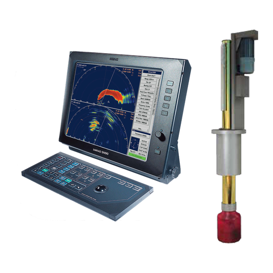
Simrad SX90
Fish finding sonar
www.simrad.com
T E C H N O L O G Y
F O R
S U S T A I N A B L E
F I S H E R I E S
Related Manuals for Simrad SX90 — REV D
Summary of Contents for Simrad SX90 — REV D
-
Page 1
Operator manual Simrad SX90 Fish finding sonar www.simrad.com T E C H N O L O G Y F O R S U S T A I N A B L E F I S H E R I E S… -
Page 3
Simrad SX90 Operator manual This manual provides you with the basic information required to operate the Simrad SX90 Fish finding sonar. For more detailed information about menus and parameters, refer to the Simrad SX90 Reference manual. WARNING: The Simrad SX90 sonar must never be powered up when the ship is in dry dock. -
Page 4
Support If you require maintenance on your Simrad product contact your local dealer. You can also contact us using the following address: simrad.support@simrad.com. If you need information about our other products, visit www.simrad.com. On our web site you will also find a list of our dealers and distributors. -
Page 5: Table Of Contents
Operator manual Table of contents ABOUT THIS MANUAL …………7 SIMRAD SX90 FISH FINDING SONAR…….. 8 Important matters …………………8 Basic information …………………8 GETTING STARTED…………10 Power on/off procedures………………10 How to perform basic operations …………….12 Echo presentation and menu ……………. 12 Temporary menu………………
-
Page 6
Simrad SX90 Storage procedures ………………..32 How to store sonar images…………….32 How to recall sonar images…………….33 How to keep sonar images …………….34 How to delete sonar images …………….. 34 How to rename sonar images …………… 35 How to print sonar images …………….36 How to burn sonar images on a CD ………….. -
Page 7
Operator manual Messages ……………………61 BASIC THEORY…………..63 Settings ……………………63 What is TVG? ……………….. 63 What is AGC? ……………….. 64 What is the PP Filter?……………… 64 About pulse form and length……………. 64 About beam widths ………………65 About Gain………………..65 What is RCG? ……………….. 66 About search sectors ………………. -
Page 8
Simrad SX90 307672/D… -
Page 9: About This Manual
Purpose The purpose of this operator manual is to present the descriptions and procedures required to operate the Simrad SX90 Fish finding sonar system in a safe and efficient manner. It is not possible to describe all functions and parameters in detail. It is therefore also important that you study the other documents that are provided with your sonar.
-
Page 10: Simrad Sx90 Fish Finding Sonar
Simrad SX90 SIMRAD SX90 FISH FINDING SONAR Study this chapter to familiarize yourself with the Simrad SX90 Fish finding sonar system. Important matters As with all advanced instruments, there are a few important matters about the SX90 that you must remember.
-
Page 11
In addition to the traditional single frequency transceiver system, the Simrad SX90 Fish finding sonar contains an advanced frequency modulated filter system (FM). The cylindrical multi-element transducer allows the omnidirectional sonar beam to be tilted electronically down to -60 degrees. -
Page 12: Getting Started
Simrad SX90 GETTING STARTED Please find the basic information required to get you started up. Power on/off procedures These procedures explain how to switch the sonar system on and off. How to switch on the sonar Press the button on the colour display monitor.
-
Page 13
Getting started Please note: • If the sonar system has been disconnected from AC power, the Processor and Beamformer Units must be started manually. Remove the protective panels on the front panels (above the fans), and use the on/off switch. •… -
Page 14: How To Perform Basic Operations
Simrad SX90 How to perform basic operations Observe this brief procedure to familiarize yourself with the basic operations with echo presentations and menu operations. Echo presentation and menu Once the sonar system is up and running, observe the layout of the display presentation: •…
-
Page 15
Getting started Observe that the menu reappears on the left hand side, and that the remaining echo presentation area is not re-scaled. Move the cursor towards the right side of the display again, and observe that the temporary menu disappears. On the Operating Panel, press the button one more Menu… -
Page 16: The Menu Structure
Simrad SX90 The menu structure The menu on the right hand side of the sonar display contains several different buttons, tabs and parameter dialogs. The following elements are in use on the menu: : This field simply states the Sonar type name of the sonar.
-
Page 17: Control The Cursor
Getting started Control the cursor Operate the trackball (A) on the Operating Panel. Observe that the cursor moves on the sonar display, and that it changes its form depending on its location. Observe the location of the button (B). Select Press this button to make a selection.
-
Page 18: Changing A Parameter Value
Simrad SX90 Changing a parameter value Observe this generic procedure to change a parameter value. Once you have gained more experience, and have become more familiar with the available options, you will select the parameters directly from the buttons. Figure 3 Changing a parameter value Move the cursor to the middle of the menu button (A).
-
Page 19: Visual Aids
Default setting Setup dedicated parameter dialog is used. In the Simrad SX90 sonar, all parameters are stored. This function will cause the sonar to remember all the selected parameter settings, even when the sonar is switched off. Visual aids…
-
Page 20
Simrad SX90 Move the cursor with the button depressed. Observe Select that the boundary line is moved. Release the button. Select Observe that the boundary line has been relocated to the new cursor position. 307672/D… -
Page 21: Cosmetics
Getting started Cosmetics The choices in the menu allows you to enable or Cosmetics disable a range of visual aids in the sonar picture. Click the tab to open the menu. Display Display Click the button to open the menu. Cosmetics Cosmetics Observe a range of parameters available to provide you with…
-
Page 22
Simrad SX90 Figure 6 Variable Range Marker (D), Compass Card (E) and Vertical Ring (F) (D) consists of an adjustable Variable Range Marker (VRM) range ring with range read-out. It can be used for any type of distance marking relative to the vessel. To adjust the marker,… -
Page 23: On-Line Help
On-line help The Simrad SX90 sonar is equipped with a comprehensive on-line help system. Help is provided in two levels: On-line and Free. It is available from all the parameter dialogs and menus by clicking the button.
-
Page 24
Simrad SX90 the information is accessed using the menu on the left hand side and interactive links throughout the document. Click in the Free bottom left corner to return to the small on-line dialog, or Close to exit the interactive manual. -
Page 25: Operational Procedures
Operational procedures OPERATIONAL PROCEDURES This chapter presents how to perform the most common procedures on the SX90 sonar. Note that the power on/off procedures have been previously explained. Topics • Power on/off procedures on page 10 • Menu procedures on page 23 •…
-
Page 26: How To Simplify The Menu
Simrad SX90 Open the menu, and click Display Full screen: On How to simplify the menu You can easily reduce the number of buttons on the sonar menus. This can be useful if you never use them. Procedure Click the tab to open the menu.
-
Page 27: How To Adjust The Agc
Operational procedures Click the left or right side of the button to decrease or Gain increase the gain, or the middle of the button to open the parameter dialog. For more information about this parameter, see About Gain on page 65. How to adjust the AGC (Automatic Gain Control) adjusts the gain in the sonar preamplifier circuitry.
-
Page 28: How To Adjust The Tvg
Simrad SX90 Click the left or right side of the button to decrease or increase the setting, or the middle of the button to open the parameter dialog. For more information about this parameter, see What is RCG? on page 66.
-
Page 29: Mode Procedures
Operational procedures Mode procedures This section explains how to choose operational modes, and how to set up the buttons on the SX90 Operating Unit. Mode How to select operational mode Your SX90 sonar is equipped with several operational modes. Observe these procedures to choose the mode best fit for your current operations.
-
Page 30: How To Sort The Operational Modes
Simrad SX90 How to sort the operational modes Your SX90 sonar provides you with a selection of operational modes. This list of modes can be sorted to suit your preferences. The top four modes on your list can be accessed by pressing the four buttons on the Operating Panel.
-
Page 31: How To Add An Own Ship Symbol
Operational procedures A triangular symbol with a corresponding number will appear on the screen over the target, while position data for the defined marker is displayed in the menu. Objects • The system continues to track the markers even when outside the sonar range.
-
Page 32
This is a useful aid in providing an overview of the trawl operation. Trawl data can be set manually using the menu or automatically by interfacing a Simrad FS trawl sonar or Simrad ITI trawl monitoring system with the sonar. -
Page 33: How To Investigate Marker And Symbol Information
Operational procedures Click once on the gear you wish to use. Click the button at the bottom of the parameter Edit Gear dialog. For each of the gear parameters available, select the requested value. Click when all the parameters have been defined. Close How to investigate marker and symbol information…
-
Page 34: Storage Procedures
Simrad SX90 Procedure Click the tab to open the menu. Objects Click on the object that you wish to delete. Click the button at the bottom of the list. Delete Alternative method Place the cursor on the object. Press the…
-
Page 35: How To Recall Sonar Images
Operational procedures Once the recording has been activated, the sonar will save sonar images as defined by the setting. Each Store mode image is added to the list of temporary files located below the buttons. Each file name reflects the date and time. Record a single image Either: Click the…
-
Page 36: How To Keep Sonar Images
Simrad SX90 The chosen image will be displayed. The phrase “RECALL” is used to indicate that a recalled image has replaced the sonar image. Click the button on the Operating Panel to restore Object normal operation. To recall several images…
-
Page 37: How To Rename Sonar Images
Operational procedures Click the tab to open the menu. Setup Click the button to open the menu. Store/Recall Store/Recall Observe the list of images in the menu. Store/Recall Click one of the images to select it. Click the button at the bottom of the file fields to Delete delete the selected image.
-
Page 38: How To Print Sonar Images
Simrad SX90 How to print sonar images Observe the following procedure to print selected sonar images. Click the tab to open the menu. Setup Click the button to open the menu. Store/Recall Store/Recall Observe the list of images in the menu.
-
Page 39: How To Copy Sonar Images To A Usb Memory Stick
Operational procedures How to copy sonar images to a USB memory stick The SX90 Processor Unit is provided with several USB interface ports. These are located on the rear side of the cabinet, and on some models below the CD player under the front cover. Observe the following procedure to copy selected sonar images over to a USB memory stick.
-
Page 40: How To Start The Vertical Search Program
Simrad SX90 Procedure Press the button in the field on the Auto search Train Operating Panel to start the horizontal search program. Hold the button depressed while you also press Auto search one of the two buttons in the field.
-
Page 41: How To Enable Position Track
Operational procedures Observe that the centre of the vertical search sector is adjusted accordingly. To exit the search program, press the button. Manual How to enable position track Observe this procedure to initiate a position track. Place the cursor over the desired location. Press the button in the field on the…
-
Page 42: How To Add A Target Tracking Line
Simrad SX90 Figure 9 Target tracking with related symbols The vector (C) originating from the target’s centre indicates its course and speed. The length of the vector increases relative to the target’s speed. One knot is represented by a small mark on the vector.
-
Page 43: User Setting Procedures
Operational procedures Observe that the parameter dialog opens below Target track the menu. Choose the length of the tracking line, and click to exit. Close User setting procedures This section explains how to handle user and default settings on the SX90 sonar. How to save the current user setting Observe the following procedure to save the current user settings.
-
Page 44: How To Delete A User Setting
Simrad SX90 Procedure Click the tab to open the menu. Setup Click the button to open the parameter dialog. User setting Click the one of the user settings on the list to select it. Click the button. Rename • Observe that a parameter dialog opens to present the current name.
-
Page 45: Installation Of Options
Optional functionality may be added to the SX90 sonar. All options are pre-programmed into the standard sonar version, and that Simrad offer a 1 month free test period for certain options. When ordering a permanent option installation, a code word will be released from Simrad. For a free test, or permanent option installation, use the following procedures.
-
Page 46
: This field displays the unique 12-character hardware HWID identification code. This code is different for each SX90 sonar. Simrad uses this code to generate the 32-character code word used for a permanent option installation. • : Each will start the 1 month free test period for the chosen option. -
Page 47: Display Modes
Display modes DISPLAY MODES The SX90 sonar provides you with several different display modes. These have been created to cover all your operational needs for various types of fishing and fishing gear. Bow up When Bow up mode is selected, the vessel symbol is stationary on the screen with the bow pointing upwards.
-
Page 48
Simrad SX90 Bow up/180° Vertical When the Bow up/180° Vertical mode is selected, the upper part of the screen shows a curtailed Bow up presentation, while the lower part shows a 180 degrees Vertical slice presentation. This mode is mainly intended for trawlers, where the vertical view acts as a multibeam echo sounder. -
Page 49
Display modes Dual 1 The Dual 1 mode is a kind of “two sonars in one” operation, where each presentation is updated for every second transmission. All settings can be set individually for each of the two presentations. This makes the dual mode especially useful for optimizing settings by directly comparing the two presentations. -
Page 50: Operating Panel
Simrad SX90 OPERATING PANEL The frequently used functions are directly accessible by the designated control buttons on the Operating Panel, and may enter operational commands directly. The buttons are grouped in fields according to their purpose. Most sonar functions are also…
-
Page 51
Operating panel Gain This is where you set up the gain in both horizontal and vertical presentations. See Gain adjustment procedures on page 24. Range This is where you select the range in the horizontal and vertical presentations. Cursor The trackball is used to move the cursor on the display. The Menu button is used to hide the menu, while the button is used to… -
Page 52: Menu Descriptions
Simrad SX90 MENU DESCRIPTIONS The Simrad SX90 sonar is equipped with an extensive menu system, and you will use this to choose parameters for the various operational modes. In order to select active menu and to click the various buttons, you must use the cursor. The cursor is controlled by the trackball on the Operating Panel, and to “click”…
-
Page 53: Horizontal Menu
Menu descriptions Horizontal menu Menu description menu is used to control the Horizontal horizontal presentations. The parameters chosen are present in all display modes. When a horizontal parameter setting is selected and defined in one mode, the chosen settings will automatically be applied to all modes.
-
Page 54
Simrad SX90 • : On the SX90 you can alter the sonar’s Frequency transmission frequency. This is very useful to eliminate interference from other equipment on board, or from other vessels in the vicinity. • : Time Varied Gain. This function will automatically adjust the gain in the sonar to compensate for geometric spread and absorption. -
Page 55: Vertical Menu
Menu descriptions Vertical menu Menu description menu is only shown in modes Vertical with a vertical slice function. All relevant settings, except the , can be TX Power selected separately for the vertical modes independent of the horizontal settings. When any vertical setting is selected and defined in one mode, the setting will be applied to all vertical modes.
-
Page 56: Vertical 180 Menu
Simrad SX90 • : Automatic Gain Control. This function will automatically reduce the gain if you experience reverberation and noise, or increase it if the conditions permit it. Using the AGC will ensure best possible signal processing. • : Reverberation Controlled Gain. This function will automatically remove unwanted reverberation from the bottom or from the sea surface.
-
Page 57
Menu descriptions • : This setting controls the amplification of the received Gain echoes in the vertical presentation. If you activate the (Automatic Gain Control) function, this gain setting is influenced. • : Use this function to select the form of the Pulse Form transmitted pulse. -
Page 58: Display Menu
Simrad SX90 Display menu Menu description menu is shown in all display Display modes, and provides access to parameters controlling the visual presentation of the sonar views. Some of the choices on the menu are simple on/off buttons. Menu buttons •…
-
Page 59: Setup Menu
Menu descriptions • : Choose the menu language. Language • : Allows you to choose the units used by the sonar. Units • : Click to access the menu, which allows Cosmetics Cosmetics you to control the amount of support information on the sonar picture.
-
Page 60
• : This function makes it possible to External sync(hronisation) eliminate interference from other Simrad sonars on board your vessel. If the sonars are connected together, you can use these settings to synchronise their transmissions. • : This function makes it possible to set up the… -
Page 61: Objects Menu
Menu descriptions • : This function is used to store the parameter User setting settings for different type of fisheries, or individual user related settings. • : Click this button to retrieve the default Default Setting factory settings. Objects menu Menu description menu is shown in all display modes, and displays the Objects…
-
Page 62: System Test Menu
Simrad SX90 System Test menu menu is activated by the button in the System test Test Setup menu. This menu provides several sensor measurements and test functions for operational and functional tests. Note that tests are designed only to be carried out by qualified service engineers.
-
Page 63: Geoview Menu
Menu descriptions GeoView menu menu provides control of selected parameters GeoView related to the current data displayed in the horizontal view; the scale and target track. It also provides you with a button to reposition the vessel symbol. The menu is identical to GeoView2 .
-
Page 64
Simrad SX90 Figure 11 The Message Bar buttons Each menu displays the warning, alarm and error messages issued by the sonar. Each message is identified with time of issue and a heading. Additional information is found in the small text field below the message list. -
Page 65: Basic Theory
Basic theory BASIC THEORY This chapter explains some of the basic theory related to settings, error sources and noise conditions. Settings A sonar will transmit a sound wave into the water around the vessel. When this sound wave hits fish, bottom, or other objects in the water, a part of the sound will be returned as echoes.
-
Page 66: What Is Agc
Simrad SX90 What is AGC? AGC means “Automatic Gain Control”. If you wish the SX90 sonar to control its own gain automatically, you must enable this function. You can choose from three different levels. When the AGC has been switched on, the manual…
-
Page 67: About Beam Widths
Basic theory About beam widths A narrow beam will always reach further than a wide beam. This is because the transmitted power of the sonar is concentrated. Nevertheless, you can easily “miss” a school of fish if you make the beam too narrow. If the range is reduced, it is the common to use a wider beam.
-
Page 68: What Is Rcg
Simrad SX90 What is RCG? RCG means “Reverberation Controlled Gain”. This function compare the strength from each echo, and then automatically adjust the range and echo level in the sonar picture. The RCG will remove unwanted echoes from the sea surface and the bottom.
-
Page 69: About Tilt
Basic theory About tilt The sonar beam can be tilted vertically in steps of 1 degree, and the chosen tilt is shown on the sonar picture. At 0 degrees tilt you will transmit the sonar beam in parallel with the sea surface, while 90 degrees tilt will direct it straight down.
-
Page 70: Cavitation
Simrad SX90 The most common cause of acoustic noise is the propeller and the cavitation caused by its rotation. Other typical noise sources on board your vessels are winches, refrigerating plants, power generators, pumps and cranes. If you experience problems you think are caused by noise, try to find out which system that causes the noise, and contact your dealer for advice.
-
Page 71: Blocking
Basic theory the bottom, you will still be able to identify the school of fish. In situation (B) you will be able to identify the upper school of fish, but the lower school will be hidden in the shadow of the rock. Be aware of that other vessels close to you will also generate reverberation due to the water disturbance caused by the wake, the propellers and the cooling water spill.
-
Page 72: Layers And Deflections
Simrad SX90 Layers and deflections Your sonar operations may also be disturbed by environmental situations that you are unable to control. Two typical conditions are temperature and salinity layers, and deflections caused by increasing or decreasing water temperature. Temperature and salinity layers You may experience that temperature and/or salinity layers exist in the water column.
-
Page 73
Basic theory When the temperature decreases (A) closer to the bottom, the sonar beam is deflected down as indicated by the illustration. The school of fish (B) you thought you would see is not visible at all. On cold days, you may experience the opposite: the cold water will be close to the surface, and the water temperature increases with increasing depth. -
Page 74
Simrad SX90 Index 270°/Vertical Bow up/180° vertical marker, 31 mode, 47 mode, 46 sonar images, 34 Bow up/Dual vertical user setting, 42 mode, 45 Depth Dividers Bow up/Vertical description, 21 mode, 45 Description About Burn on CD display modes, 45… -
Page 75
Index adjust, 24 load Investigate display read-out, 17 factory settings, 42 marker, 31 menu button, 51, 53, 55 user setting, 41 theory, 65 move the boundary lines, 17 Gear position menu button, 57 track, 39 Keep symbol power off, 11 sonar images, 34 delete, 31 power on, 10… -
Page 76
Simrad SX90 Colour Threshold, 56 True motion/Vertical, 46 rename, 35 Colours, 56 Mode buttons store, 32 Cosmetics, 57 menu button, 56 Ping Sector Dead Reckoning, 58 Modes menu button, 51 Default Setting, 59 display, 45 Position Display Gain, 56 sort, 28… -
Page 77
Index horizontal Range menu button, 58 search program, 37 display read-out, 17 Store investigate menu button, 51, 53–54 sonar images, 32 marker, 31 Store/Recall keep adjust, 25 menu, 59 sonar images, 34 menu button, 52, 54–55 menu button, 57 load theory, 66 System test factory settings, 42… -
Page 78
Simrad SX90 line, 40 Trawl symbol use, 30 True motion mode, 46 True motion/Vertical mode, 46 adjust, 26 menu button, 52–53, 55 theory, 63 TX Power menu button, 51, 53, 55 Units menu button, 57 User setting delete, 42 load, 41… -
Page 79: 307672/D
Index 307672/D…
-
Page 80
ISBN: 978-82-8066-085-5 © 2009 Kongsberg Maritime AS…
This manual is also suitable for:
Sx90
All public documents related to this product can be accessed using the links below. The documents are provided on several formats including PDF, HTML, EPUB and/or CHM. When applicable, certain publications are available as interactive electronic technical manuals (IETM) on separate websites.
End-user documentation
-
Operation
-
Installation
-
Installation drawings
-
Software release notes
-
Sales documents
-
Certificates and declarations
Online IETM Operator manuals
-
English
-
Spanish
-
French
-
Simplified Chinese
-
Traditional Chinese
Online IETM Reference manuals
-
English
Online IETM Installation manuals
-
English
-
Spanish
-
French
Simrad SX90
-
Start page
- Manuals
- Brands
- Kongsberg Manuals
- Transducer
- Simrad SX90 Series
Manuals and User Guides for Kongsberg Simrad SX90 Series. We have 3 Kongsberg Simrad SX90 Series manuals available for free PDF download: Reference Manual, Manual, Replacement Procedure
Kongsberg Simrad SX90 Series Reference Manual (702 pages)
Fish-finding sonar
Brand: Kongsberg
|
Category: Lighting Equipment
|
Size: 6.97 MB
Table of Contents
-
Table of Contents
5
-
About this Manual
17
-
Simrad Sx90
19
-
Important
20
-
System Description
22
-
System Diagram
23
-
System Units
24
-
Display
24
-
Processor Unit
24
-
Operating Panel
25
-
Transceiver Unit
25
-
Hull Unit
26
-
Transducer
27
-
-
Order Information
29
-
General Safety Rules
30
-
Network Security
31
-
Support Information
32
-
Getting Started
35
-
Operating Panels
36
-
Operating Panel Description (Mk1)
36
-
Operating Panel Description (Mk2)
43
-
Operating Panel Description (Mk3)
47
-
Microsoft Xbox Controller Description
51
-
-
Starting Normal Operation
53
-
Turning on the SX90 System for Normal Use
53
-
Getting to Know the User Interface
55
-
Getting to Know Presentation Modes and Views
58
-
Selecting Normal Mode to Start Pinging
62
-
Adjusting the Radius of the Search Area
63
-
Adjusting the Echo Sensitivity
65
-
Changing the Vertical Angle of the Sonar Beams
67
-
Adjusting the Horizontal Direction of the Sonar Beam
69
-
Turning off the SX90 System
71
-
Power
71
-
-
Basic Operating Procedures
72
-
Selecting the Language Displayed in the Menus and Dialog Boxes
72
-
Selecting Operating Frequency for Minimum Noise
73
-
Hiding the Menu System When You Do Not Need It
74
-
Saving Single or Sequential Screen Captures
75
-
Saving the Current User Settings
76
-
Defining the Ping (Transmission) Modes
77
-
-
Context-Sensitive Online Help
78
-
Operating Procedures
80
-
Getting Started
81
-
Turning on the SX90 System
81
-
Processor Unit Is Turned on
81
-
Caution
81
-
Procedure
81
-
Make Sure that You Have Sufficient Water Depth below the Keel before You Lower the Transducer
81
-
Turn on the Display(S)
81
-
On the Operating Panel, Press
81
-
Power , and Keep It Depressed for a few Seconds
81
-
Lowering and Hoisting the Transducer from the User Interface
83
-
Turning off the SX90 System
84
-
-
Choosing Operating Mode and Key Transmit Parameters
85
-
Selecting Normal Mode to Start Pinging
85
-
Selecting Replay Mode
86
-
Selecting Normal Mode to Start Pinging
86
-
Selecting Inactive Mode
88
-
Setting up the SX90 System for Maximum Echo Refresh Rate
89
-
Transmitting Single Pings
90
-
Transmitting with Fixed-Time Intervals
91
-
Adjusting the Output Power to Match Varying Conditions
92
-
Selecting the Best Operating Frequency
93
-
Open the
93
-
-
Controlling the Gain and Range Settings
95
-
Adjusting the Gain (Echo Sensitivity)
95
-
Adjusting the TVG (Time Variable Gain) Setting
97
-
Adjusting the Sonar Range
98
-
Expanding the Range Within the Sonar View
100
-
Adjusting the Intensity of the Echo Presentations
101
-
Changing the Tilt
101
-
Adjusting the Bearing
103
-
-
Using the Markers and Tracking Features
106
-
Starting a Position Track
106
-
Starting a Target Track
107
-
Placing a New Marker
109
-
Deleting a Marker
110
-
Measuring the Size of a School Relative to the Purse seine
110
-
Using Visual Aids During the Purse seine Catch Phase
111
-
Selecting a Geographical Area for Accurate Target Tracking
113
-
Defining the Physical Size of the Tracking Area
115
-
Choosing the Fishing Gear in Use
116
-
Changing the Fishing Gear Properties to Match Your Own Equipment
117
-
-
Improving the Recognition of Fish and Schools Using Receiver Filters
119
-
About the Receiver Filter Sequence in the SX90 System
120
-
Reducing Noise and Reverberation with the AGC (Automatic Gain Control) Function
121
-
Reducing Propeller Noise and Interference with the Noise Filter
122
-
Reducing Bottom and Surface Reverberation with the RCG (Reverberation Controlled Gain) Function
123
-
Reducing Noise and False Echoes with the Ping-Ping Filter
125
-
Reducing the Strong Bottom Echo to See Fish Close to the Seabed
126
-
Adjusting the Intensity of the Echo Presentations
127
-
-
Recording and Replaying Echo Data
128
-
Defining the File and Folder Settings for Data Recording
128
-
Recording Echo Data
129
-
Accessing the Echo Data Files to Delete, Move or Copy Them
130
-
Selecting Replay Mode
131
-
Choosing Which Echo Data File(S) to Replay
133
-
-
Recording and Exporting Processed Echo Data
135
-
Defining the Processed Data Recording Parameters
135
-
Recording Processed Data
136
-
Accessing the Processed Data Files to Delete, Move or Copy Them
138
-
-
Capturing the Display Presentation in Image and Video Files
140
-
Capturing the Display Presentation in an Image
140
-
Capturing the Display Presentation Using One Image for each Ping
141
-
Choosing Screen Capture Mode
142
-
Accessing the Screen Capture Images to Delete, Move or Copy Them
143
-
Capturing the Display Presentation in a Video File
144
-
Selecting Where to Save the Video Files
145
-
-
Setting up Presentation Modes and Views
147
-
Moving a View to Another Display
147
-
Rearranging the Layout of the Echo Presentations
148
-
Restoring the Locations and Sizes of the Views
149
-
-
Defining the Visual Information in the Sonar Views
151
-
Selecting True or Relative Motion Behaviour in the Views
151
-
Placing Data from a Sea Current Sensor in the Sonar View
152
-
Adding Markers for External Objects to the Echo Presentation
153
-
-
Using Maps
154
-
Enabling and Disabling the Map Presentation
154
-
Selecting Which Map Elements to Include in the Display Presentation
155
-
Setting up the Presentation of the Depth Lines in the Map
156
-
Choosing a Map Provider
156
-
-
Defining Settings Related to User Preferences and Individual Customizing
158
-
Selecting Menu Language
158
-
Hiding the Menu System
159
-
Placing the Menu on the Left Side of the Display Presentation
160
-
Selecting the Information to Appear on the Top Bar
161
-
Enabling Coordinated Universal Time (UTC) on the Bottom Bar
161
-
Selecting Which Tooltips to Appear in the User Interface
162
-
Adjusting the Backlight Intensity on the Operating Panel
163
-
Reducing the Light Emitted from the Display Presentation
164
-
Increasing the Visibility of the Information Panes
164
-
Changing the Colour Palette («Skin») Used in the Display Presentations
165
-
Choosing the Colours Used to Present the Echoes
166
-
Selecting Measurement Units
167
-
Configuring the Environmental Parameters
168
-
Setting up the Alarm Limits for System Protection
168
-
Defining the Middle Position of the Transducer
171
-
-
Saving, Retrieving and Handling User Settings
173
-
Saving the Current User Settings
173
-
Choosing Previously Saved User Settings
174
-
Renaming Existing User Settings
175
-
Deleting User Settings that Are no Longer Used
176
-
Choosing Factory Default Settings
177
-
-
Defining the User-Selected Features on the Operating Panel
178
-
Selecting Which Operating Panel to Use
178
-
Assigning User Settings or Presentation Modes to the Operating Panel
179
-
Assigning Functions to the Rotary Switches on the Operating Panel
181
-
Assigning Functions to F1, F2 and F3 on the Operating Panel (Mk2)
182
-
-
Exporting Sensor Data, Marker Positions and Technical Information
185
-
Exporting Target Markers
185
-
Exporting Sensor Data to a Peripheral System
187
-
Exporting Technical Information
188
-
-
Maintenance Procedures
190
-
Lowering and Hoisting the Transducer from the Sonar Room
191
-
Lowering and Hoisting the Transducer Using the Hoist/Lower Switch
192
-
Lowering and Hoisting the Transducer Using the Hand Crank
194
-
Emergency Lowering and Hoisting Using the Two Contactors
196
-
-
Setting up the Interfaces to Peripheral Devices
199
-
Installing Navigation Sensors and Other Sensors
199
-
Defining the Serial and Ethernet (LAN) Port Parameters
200
-
Setting up the Input from a Navigation System (GPS)
202
-
Setting up the Interface for Speed Log Input
205
-
Setting up the Interface for Course Gyro Input
207
-
Configuring the Sensor Interface
209
-
Setting up the Input from a Motion Reference Unit (MRU)
211
-
Setting up the SX90 System for Synchronized Operation
213
-
Setting up Input from Buoys, Fish Aggregating Devices and Other External Objects
216
-
-
Inserting the Installation Parameters
219
-
Inserting the Ship Origin and Dimensions
219
-
Inserting the Installation Parameters for the Transducer
222
-
Inserting the Installation Parameters for the Motion Reference Unit (MRU)
225
-
Adjusting the Built-In Motion Sensor Offset
228
-
Adjusting the Stabilization Offsets for the External Motion Sensor
230
-
-
Installing and Maintaining Software
234
-
Installing a New Version of the Operating Software
234
-
Removing the Operating Software
236
-
Updating the Online Help System
237
-
Adding Online Help in a New Language
238
-
Obtaining and Installing a Software License for Additional Functionality
240
-
Setting up the Operating Panel (Mk2)
242
-
Using more than One Operating Panel to Control the Sonar (Mk2)
245
-
Using a Single Operating Panel to Control more than One Sonar (Mk2)
249
-
Updating the Operating Panel Support Applications (Mk2)
253
-
Updating the Firmware on the Operating Panel (Mk2)
255
-
-
Testing the Noise Conditions and the Sonar Functionality
258
-
Checking the Status of the Transceiver Boards
258
-
Checking the Transducer by Means of the Diagnostics Functionality
260
-
Measuring the Noise in Passive Mode
264
-
Making a Noise/Speed Curve to Determine Vessel Noise
266
-
Measuring Flow Noise
270
-
-
Preventive Maintenance
276
-
Preventive Maintenance Schedule
277
-
Requirements for Personnel and Tools
279
-
Approved Anti-Fouling Paints
280
-
Preventive Maintenance Procedures
282
-
Accessing the Inside of the Installation Trunk
303
-
-
User Interface
309
-
User Interface Familiarization
310
-
Top Bar
312
-
Top Bar Overview
312
-
Logo and Product Name
314
-
Menu
315
-
Screen Recording
315
-
Screen Capture
316
-
Record
317
-
Hull Unit
318
-
Information Panes Overview
319
-
Navigational Information
321
-
Messages
325
-
Help
325
-
Operating System Functions
326
-
-
Replay Bar Description
328
-
Sonar Views
330
-
Presentation Modes
331
-
Horizontal View
332
-
Vertical View
340
-
Inspection View
344
-
Plane View
347
-
Echogram View
350
-
Catch View
352
-
270 Vertical View
355
-
-
Using Markers in the SX90 User Interface
360
-
Place Marker
361
-
Target Markers
364
-
Circle Marker
367
-
Own Ship Marker
367
-
Gear Symbol
369
-
Rulers
370
-
-
About Target Tracking
371
-
About Position Tracking
373
-
Information Panes
377
-
Biomass Information Pane Description
378
-
Size Distribution Information Pane Description
380
-
Fish Position Information Pane
383
-
Zoom Information Pane
385
-
-
Bottom Bar
387
-
Menu System
389
-
About the Menus and Menu Buttons
390
-
Using the «Smart» Menu Buttons
391
-
Main Menu
393
-
Operation Menu
395
-
Display Menu
398
-
Setup Menu
402
-
Active Menu
409
-
Objects Menu
414
-
Visual Objects Menu
419
-
Cosmetics Menu
423
-
Shortcut Menus
426
-
Functions and Dialog Boxes
430
-
Main Menu; Functions and Dialog Boxes
431
-
User Settings Dialog Box
431
-
Range Function
434
-
Gain Function
436
-
Tilt Function
437
-
Bearing Function
440
-
-
Operation Menu; Functions and Dialog Boxes
444
-
Operation Function
445
-
Transmission Mode Function
446
-
Tx Power Function
447
-
Record RAW Function
448
-
Record Processed Function
450
-
Output Dialog Box
452
-
Audio Function
452
-
-
Display Menu; Functions and Dialog Boxes
454
-
Visual Objects Function
455
-
Cosmetics Function
455
-
Motion Function
456
-
Transparency Function
457
-
View Range Function
458
-
Display Gain Function
458
-
Panel Backlight Function
460
-
Colour Threshold Function
461
-
Screen Brightness Function
461
-
Display Options Dialog Box
462
-
Colour Setup Dialog Box
463
-
Docking Views Function
464
-
-
Setup Menu; Functions and Dialog Boxes
466
-
Tracking Area Function
467
-
Fishing Gear Function
468
-
Fish Select Dialog Box
469
-
Environment Dialog Box
469
-
Language Function
470
-
Dead Reckoning Function
471
-
Stabilization Function
472
-
Screen Captures Dialog Box
473
-
Beam Visualization Dialog Box
475
-
Diagnostics Dialog Box
476
-
Export Dialog Box
477
-
Installation Dialog Box
478
-
About Dialog Box
479
-
-
Active Menu; Functions and Dialog Boxes
480
-
TVG Function
481
-
Ping-Ping Filter Function
483
-
Pulse Type Function
486
-
Bandwidth Function
489
-
Frequency Function
490
-
Horizontal TX Sector Function
491
-
Vertical TX Sector Function
493
-
Range Projection Function
495
-
AGC (Automatic Gain Control) Function
496
-
RCG (Reverberation Controlled Gain) Function
498
-
Bottom Filter Threshold Function
501
-
Noise Filter Function
502
-
Horizontal Scroll Function
504
-
Vertical Reference Function
505
-
Echogram Dialog Box
506
-
Information Pane Options Dialog Box
506
-
-
Secondary Functions and Dialog Boxes
508
-
Replay File Dialog Box
508
-
Recording Dialog Box
511
-
LAN Port Setup Dialog Box
512
-
Serial Port Setup Dialog Box
515
-
Add Serial Port Dialog Box
517
-
Port Monitor Dialog Box
518
-
Messages Dialog Box
519
-
Tracking Area Setup Dialog Box
522
-
Add Fishing Gear Dialog Box
523
-
Auto Configuration Dialog Box
524
-
Hull Unit Control Dialog Box
524
-
New Marker Dialog Box
525
-
Power off Dialog Box
526
-
-
Pages in the Output Dialog Box
527
-
File Setup Page
527
-
I/O Setup Page
530
-
Processed Data to File Page
534
-
Marker Output Page
537
-
Relay Output Page
539
-
Screen Recording Page
542
-
-
Pages in the Display Options Dialog Box
544
-
General Page
544
-
Map Display Page
547
-
Safety Depth Page
549
-
Tooltip Page
551
-
Own Ship Page
552
-
Vertical View Orientation Page
553
-
Off Centre Page
553
-
Current Flow Page
555
-
-
Pages in the Diagnostics Dialog Box
557
-
Processor Page
558
-
Sensors Page
560
-
Transceiver Page
561
-
Transducer Page
563
-
Noise Page
566
-
Element BITE Dialog Box
568
-
B-Scan Page
569
-
Matrix Page
574
-
-
Pages in the Installation Dialog Box
578
-
Sensor Installation Page
579
-
Sensor Configuration Page
584
-
Motion Reference Unit Page
587
-
Installation Parameters Page
590
-
Synchronization Page
596
-
Units Page
599
-
Operating Panel Page
601
-
Echogram Settings Page
611
-
Hull Unit Configuration Page
612
-
System Protection Page
613
-
Fishing Gear Setup Page
616
-
Map Setup Page
617
-
User Settings Setup Page
619
-
Software License Page
620
-
Transceiver Upgrade Page
621
-
Simrad Connect Page
622
-
-
Pages in the Echogram Dialog Box
623
-
Lines Page
623
-
Echogram Page
626
-
Horizontal Axis Page
629
-
-
Pages in the Information Pane Options Dialog Box
631
-
Size Distribution Page
631
-
Fish Position Page
634
-
Fish Size Adjustment Page
637
-
School Mass Adjustment Page
638
-
-
Concept Descriptions
640
-
Vessel Coordinate System
641
-
Layers and Deflections
644
-
Temperature and Salinity Layers
644
-
Sonar Beam Deflections
645
-
-
What Is Sampling
646
-
Acoustic Noise
647
-
Introduction to the Acoustic Noise Challenge
647
-
Contributing Factors
647
-
Self Noise
649
-
Ambient Noise
652
-
Electrical Self Noise
652
-
Reverberation
653
-
Some Means to Reduce Acoustic Noise
654
-
-
Technical Specifications
657
-
Introduction to Technical Specifications
658
-
Performance Specifications
658
-
Power Requirements
662
-
Display Power Requirements
662
-
Operating Panel Power Requirements (Mk1)
662
-
Operating Panel Power Requirements (Mk2)
663
-
Operating Panel Power Requirements (Mk3)
663
-
Transceiver Unit Power Requirements
663
-
Hull Unit Power Requirements
664
-
-
Weights and Outline Dimensions
665
-
Display Weight and Outline Dimensions
665
-
Enix Processor Unit Weight and Outline Dimensions
665
-
Operating Panel Weight and Outline Dimensions (Mk1)
666
-
Operating Panel Weight and Outline Dimensions (Mk2)
666
-
Operating Panel Weight and Outline Dimensions (Mk3)
666
-
Transceiver Unit Weight and Outline Dimensions
667
-
Hull Unit Weight and Outline Dimensions
667
-
-
Environmental Requirements
669
-
Display Environmental Requirements
669
-
Processor Unit Environmental Requirements
669
-
Operating Panel Environmental Requirements (Mk1)
670
-
Operating Panel Environmental Requirements (Mk2)
670
-
Operating Panel Environmental Requirements (Mk3)
671
-
Transceiver Unit Environmental Requirements
671
-
Hull Unit Environmental Requirements
671
-
-
Compass Safe Distance
673
-
Display Compass Safe Distance
673
-
Processor Unit Compass Safe Distance
673
-
Operating Panel Compass Safe Distance (Mk1)
674
-
Operating Panel Compass Safe Distance (Mk2)
674
-
Operating Panel Compass Safe Distance (Mk3)
674
-
Transceiver Unit Compass Safe Distance
674
-
Hull Unit Compass Safe Distance
675
-
-
Minimum Display Requirements
675
Advertisement
Kongsberg Simrad SX90 Series Manual (34 pages)
Brand: Kongsberg
|
Category: Fishing Equipment
|
Size: 0.83 MB
Table of Contents
-
Table of Contents
3
-
Software Changes
5
-
Do I Need to Upgrade
7
-
Software Licenses
8
-
Software Installation
9
-
Removing the Operating Software
9
-
Installing a New Version of the Operating Software
11
-
Settings You Need to Restore after a Software Upgrade
12
-
End-User Documentation
13
-
Updated Functions and Dialog Boxes
14
-
User Settings Setup Page
14
-
Units Page
15
-
New Marker Dialog Box
17
-
Operating Panel Page
17
-
Operating Panel Mk2
19
-
Operating Panel Mk3
23
-
Display Options Dialog Box
26
-
General Page
26
-
Minimum Display Requirements
30

Kongsberg Simrad SX90 Series Replacement Procedure (14 pages)
Brand: Kongsberg
|
Category: Transducer
|
Size: 0.46 MB
Table of Contents
-
Table of Contents
3
-
About this Document
5
-
Logistics
6
-
Personnel Requirements
6
-
Required Tools for Transducer Replacement
6
-
Procedures
8
-
Replacing the Transducer
8
-
Transducer Replacement Introduction
8
-
Relevant Spare Parts
9
-
Unpacking a New Transducer
9
-
Dismounting the Transducer from the Bottom of the Transducer Shaft
10
-
Mounting a New Transducer to the Bottom of the Transducer Shaft
11
-
-
Replacing the Zinc Anodes
12
Advertisement
Advertisement
Related Products
-
Kongsberg Simrad SP90 Series
-
Kongsberg Simrad SU90 Series
-
Kongsberg Simrad C-All
-
Kongsberg Simrad SN90
-
Kongsberg SV Series
-
Kongsberg SR 562
-
Kongsberg SR 622
-
Kongsberg SR 642
-
Kongsberg SR 662
-
Kongsberg SR 743
Kongsberg Categories
Marine Equipment
Sonar
Marine Radio
Radio
Transceiver
More Kongsberg Manuals
Manufacturer: Kongsberg
Category: Lighting Equipment

Download Manual (6.64 MB)
Related manuals
Kongsberg Simrad SX90 Reference Manual
Lighting Equipment
Kongsberg SIMRAD SX90 Manual
Fishing Equipment
Kongsberg Simrad SP90 Series Replacement Procedure
Transducer
More by Kongsberg
Kongsberg EM 1002 Operator’s Manual
Marine Equipment
394 pages
Kongsberg cPAP30 Instruction Manual
Transceiver
33 pages
Kongsberg EM 2000 Maintenance Manual
Marine Equipment
207 pages
Kongsberg Simrad EM 300 Operation Manual
Marine Equipment
408 pages
Kongsberg Seapath 320 Technical Manual
Marine GPS System
100 pages
SEE MORE ❯
Table of Contents for Simrad SX90 — REV B:
-
Operational procedures 2 Press the Position track button in the Train field on the Operating Panel. A geographically fixed circle will appear on the display, and its position will automatically be tracked by the system with respect to the bearing and tilt angle. The track parameters can be investigated by accessing the Objects menu. When the Auto Tilt function is activated in the Position Track mode the tilt search cen
-
Operational procedures Prepare the recording parameters 1 Click the Setup tab to open the menu. 2 Click the Store/Recall button to open the Store/Recall menu. 3 Click the Store mode button to choose recording mode. Click the left side of the Store mode button to scroll down the list of options. Click the middle of the button to open the parameter dialogue for direct access to the requested setting, or click the right side of the button to scroll up the list of options. 4 Record the images. 5 Click the Close button
-
Simrad SX90 gear symbol, 28 own ship symbol, 28 target marker, 27 vessel symbol, 28 adjust AGC, 24 display gain, 25 gain, 24 RCG, 24 TVG, 25 burnonCD sonar images, 34 change gear properties, 29 change a value, 15 control the cursor, 14 copy to USB sonar images, 35 define gear properties, 29 Mode buttons, 26 delete marker, 30 sonar images, 33 user setting, 39 hide menu, 23 hide the menu, 11 horizontal search program, 36 investigate marker, 29 keep sonar images, 32 load factory settings, 39 user setting, 38 move the
-
Simrad SX90 BASIC THEORY This chapter explains some of the basic theory related to settings, error sources and noise conditions. Topics Settings on page 54 Noise and reverberation on page 58 Layers and deflections on page 60 Settings A sonar will transmit a sound wave into the water around the vessel. When this sound wave hits fish, bottom, or other objects in the water, a part of the sound will be returned as echoes. These echoes are collected by the sonar, interpr
-
Operator manual About beam widths …………………………………………………………………………. 56 About Gain……………………………………………………………………………………. 56 What is RCG? ……………………………………………………………………………….. 57 About search sectors ……………………………………………………………………….. 57 About
-
Operational procedures How to sort the operational modes Your SX90 sonar p rovides you with a selection of operational modes. This list of modes can be sorted to suit your preferences. The top four modes on your list can be accessed by pressing the four Mode buttons on the Operating Panel. To sort the modes, observe the procedure. 1 Click the Setup tabtoopentheSetup menu. 2 Click the Sort Modes button to open the Sort Modes me
-
Index Move down, 53 Move up, 53 Store/Recall, 53 structure, 13 System test, 53 tabs, 13 temporary, 12 Vertical, 47 Vertical 180, 48 Menu descriptions, 45 Minute Markers description, 20 Mode buttons define, 26 select, 26 Mode buttons button Display menu, 49 Modes display, 41 sort, 27 Move down button Sort Modes menu, 53 Move up button Sort Modes menu, 53 Movements button Setup menu, 50 N Noise, test, 60 Noise, theory, 58 O Objects menu, 52 Omni transmission theory, 57 Operating panel description, 43 Operation basic, 11 Operational modes, 41 OS Own Ship marker, 52 O
-
Index A Add circle ma rker, 27 gear symbol, 28 own ship symb ol, 28 target marker, 27 vessel symbol, 28 AGC adjust, 24 button Horizontal menu, 45 theory, 55 Apply button Sort Modes menu, 53 AT Automatic Target Track marker, 52 Audio mute button Display menu, 49 Automatic position track, 36 target track, 37 tilt program, 36 train program, 36 Automatic Target Track marker, 52 B Basic operations, 11 Beam button Horizontal menu, 45 Beam width theory, 56 Bearing button Display menu, 49 Horizontal menu, 45 displa
-
Operator manual Simrad SX90 Fish nding sonar T E C H N O L O G Y F O R S U S T A I N A B L E F I S H E R I E S www.simrad.com
-
Simrad SX90 Important matters As with all advanced instruments, there are a few important matters about the SX90 that you must remember. Before you switch on the sonar When you power up the sonar, the transducer is lowered down below the vessel’s hull. Make sure that you have sufficient water depth before you do this! Whenthesonarisnotinuse To protect the sonar when it is not in use, we strongly advice you to
-
Menu descriptions Display menu The Display menu is shown in all display modes, and provides access to parameters controlling the visual presentation of the sonar views. Some of the choices on the menu are simple on/off buttons. Buttons Full screen: Click this button to remove or retrieve the menu. Audio mute: Not used. Palette: Click this button to choose a presentation colour palette to suit your personal preferences. Display Gain: This function controls the amount of echo that are displayed. Use this control together with Gain to control
Questions, Opinions and Exploitation Impressions:
You can ask a question, express your opinion or share our experience of Simrad SX90 — REV B device using right now.