-
Contents
-
Table of Contents
-
Bookmarks
Quick Links
Questo manuale d’istruzione è fornito da trovaprezzi.it. Scopri tutte le offerte per
HD3
o cerca il tuo prodotto tra le
B365 HD3
User’s Manual
Rev. 1002
For more product details, please visit GIGABYTE’s website.
To reduce the impacts on global warming, the packaging materials of this product
are recyclable and reusable. GIGABYTE works with you to protect the environment.
migliori offerte di Schede Madri
Gigabyte B365
Summary of Contents for Gigabyte B365 HD3
 Loading…
![]()
B365 HD3
User’s Manual
Rev. 1002
For more product details, please visit GIGABYTE’s website.
To reduce the impacts on global warming, the packaging materials of this product are recyclable and reusable. GIGABYTE works with you to protect the environment.

Motherboard
B365 HD3
Motherboard
B365 HD3
Jul. 26, 2019
Jul. 26, 2019
Copyright
© 2019 GIGA-BYTE TECHNOLOGY CO., LTD. All rights reserved.
The trademarks mentioned in this manual are legally registered to their respective owners.
Disclaimer
Information in this manual is protected by copyright laws and is the property of GIGABYTE.
ChangestothespecificationsandfeaturesinthismanualmaybemadebyGIGABYTEwithoutpriornotice.
No part of this manual may be reproduced, copied, translated, transmitted, or published in any form or by any means without GIGABYTE’s prior written permission.
In order to assist in the use of this product, carefully read the User’s Manual.
For product-related information, check on our website at: https://www.gigabyte.com
Identifying Your Motherboard Revision
The revision number on your motherboard looks like this: «REV: X.X.» For example, «REV: 1.0» means the revision of the motherboard is 1.0. Check your motherboard revision before updating motherboard BIOS, drivers, or when looking for technical information.
Example:

Table of Contents
|
B365 HD3 Motherboard Layout…………………………………………………………………………… |
4 |
|
|
Chapter 1 Hardware Installation………………………………………………………………………….. |
5 |
|
|
1-1 |
Installation Precautions…………………………………………………………………………. |
5 |
|
1-2 |
Product Specifications………………………………………………………………………….. |
6 |
|
1-3 |
Installing the CPU………………………………………………………………………………… |
9 |
|
1-4 |
Installing the Memory……………………………………………………………………………. |
9 |
|
1-5 Installing an Expansion Card……………………………………………………………….. |
10 |
|
|
1-6 |
Back Panel Connectors………………………………………………………………………. |
10 |
|
1-7 |
Internal Connectors……………………………………………………………………………. |
13 |
|
Chapter 2 BIOS Setup……………………………………………………………………………………… |
21 |
|
|
2-1 |
Startup Screen…………………………………………………………………………………… |
21 |
|
2-2 |
The Main Menu………………………………………………………………………………….. |
22 |
|
2-3 |
M.I.T…………………………………………………………………………………………………. |
23 |
|
2-4 |
System……………………………………………………………………………………………… |
29 |
|
2-5 |
BIOS………………………………………………………………………………………………… |
30 |
|
2-6 |
Peripherals………………………………………………………………………………………… |
33 |
|
2-7 |
Chipset……………………………………………………………………………………………… |
36 |
|
2-8 |
Power……………………………………………………………………………………………….. |
37 |
|
2-9 |
Save & Exit……………………………………………………………………………………….. |
39 |
|
Chapter 3 Appendix…………………………………………………………………………………………. |
40 |
|
|
3-1 Configuring a RAID Set………………………………………………………………………. |
40 |
|
|
3-2 Installing an Intel® Optane™ Memory…………………………………………………….. |
42 |
|
|
3-3 |
Drivers Installation……………………………………………………………………………… |
44 |
|
Regulatory Statements…………………………………………………………………………………. |
45 |
|
|
Contact Us………………………………………………………………………………………………….. |
47 |
— 3 —

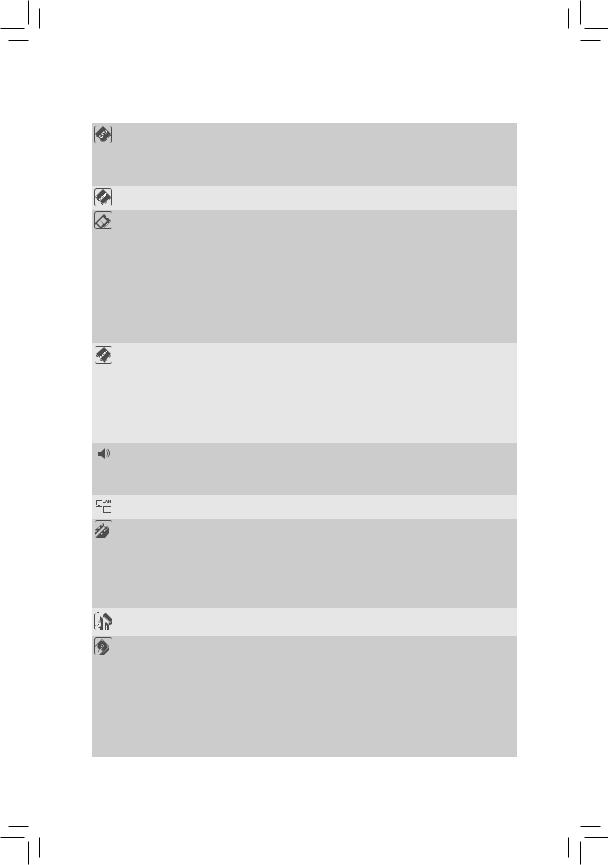
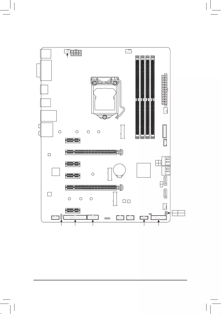
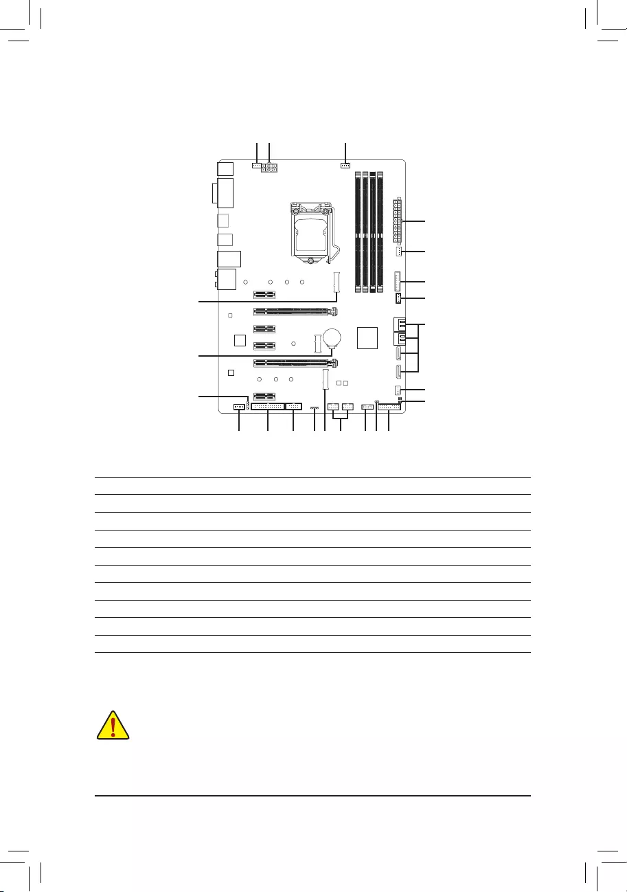
B365 HD3 Motherboard Layout
|
KB_MS_USB |
ATX_12V_2X4 |
|||
|
SYS_FAN1 |
||||
|
DVI SUB |
||||
|
D |
LGA1151 |
|||
|
HDMI |
||||
|
R_USB30 |
||||
|
USB30_LAN |
||||
|
AUDIO |
110 |
80 |
60 |
42 |
|
PCIEX1_1 |
||||
|
PCIEX16 |
B365 HD3 |
CPU_FAN
ATX
|
SYS FAN2 |
|
|
M2M |
USB30 |
|
F |
|
|
DDR4 4 DDR4 2 DDR4 3 DDR4 1 |
THB C |
|
Realtek® |
PCIEX1_2 |
||
|
GbE LAN |
|||
|
iTE® |
PCIEX1_3 |
30 |
|
|
Super I/O |
|||
|
PCIEX4 |
|||
|
CODEC |
|||
|
80 |
60 |
42 |
|
|
PCIEX1_4 |
|||
|
F_AUDIO |
|||
|
SPDIF_O |
LPT |
COM |
|
1 0 |
|||||
|
3 2 |
|||||
|
BAT |
Intel® B365 |
SATA3 |
|||
|
4 |
|||||
|
5 |
|||||
|
SATA3 |
|||||
|
B_BIOS |
M_BIOS |
FAN3 |
|||
|
F_USB2 F_USB1 |
CLR_CMOS |
SYS_ |
CPU DRAM |
||
|
VGA BOOT |
|||||
|
TPM |
F_PANEL |
Box Contents
|
55 |
B365 HD3 motherboard |
55 |
Two SATA cables |
|
55 |
Motherboard driver disc |
55 |
I/O Shield |
|
55 |
User’s Manual |
*The box contents above are for reference only and the actual items shall depend on the product package you obtain. The box contents are subject to change without notice.
—4 —

Chapter 1 Hardware Installation
1-1 Installation Precautions
The motherboard contains numerous delicate electronic circuits and components which can become damaged as a result of electrostatic discharge (ESD). Prior to installation, carefully read the user’s manual and follow these procedures:
•• Prior to installation, make sure the chassis is suitable for the motherboard.
•• Prior to installation, do not remove or break motherboard S/N (Serial Number) sticker or warranty sticker provided by your dealer. These stickers are required for warranty validation.
•• Always remove the AC power by unplugging the power cord from the power outlet before installing or removing the motherboard or other hardware components.
•• When connecting hardware components to the internal connectors on the motherboard, make sure they are connected tightly and securely.
•• When handling the motherboard, avoid touching any metal leads or connectors.
•• It is best to wear an electrostatic discharge (ESD) wrist strap when handling electronic components such as a motherboard, CPU or memory. If you do not have an ESD wrist strap, keep your hands dry and first touch a metal object to eliminate static electricity.
•• Prior to installing the motherboard, please have it on top of an antistatic pad or within an electrostatic shielding container.
•• Before connecting or unplugging the power supply cable from the motherboard, make sure the power supply has been turned off.
•• Before turning on the power, make sure the power supply voltage has been set according to the local voltage standard.
•• Before using the product, please verify that all cables and power connectors of your hardware components are connected.
•• To prevent damage to the motherboard, do not allow screws to come in contact with the motherboard circuit or its components.
•• Make sure there are no leftover screws or metal components placed on the motherboard or within the computer casing.
•• Do not place the computer system on an uneven surface.
•• Do not place the computer system in a high-temperature or wet environment.
•• Turning on the computer power during the installation process can lead to damage to system components as well as physical harm to the user.
•• If you are uncertain about any installation steps or have a problem related to the use of the product, please consult a certified computer technician.
•• If you use an adapter, extension power cable, or power strip, ensure to consult with its installation and/or grounding instructions.
— 5 —
|
1-2 |
Product Specifications |
|
|
CPU |
Support for 9th and 8th Generation Intel® Core™ i9 processors/Intel® Core™ i7 |
|
|
processors/Intel® Core™ i5 processors/Intel® Core™ i3 processors/Intel® Pentium® |
||
|
processors/Intel® Celeron® processors in the LGA1151 package |
||
|
(Go to GIGABYTE’s website for the latest CPU support list.) |
||
|
L3 cache varies with CPU |
||
|
Chipset |
Intel® B365 Express Chipset |
|
|
Memory |
4 x DDR4 DIMM sockets supporting up to 64 GB of system memory |
|
|
Dual channel memory architecture |
||
|
Support for DDR4 2666/2400/2133 MHz memory modules |
||
|
Support for ECC Un-buffered DIMM 1Rx8/2Rx8 memory modules (operate in |
||
|
non-ECC mode) |
||
|
Support for non-ECC Un-buffered DIMM 1Rx8/2Rx8/1Rx16 memory modules |
||
|
Support for Extreme Memory Profile (XMP) memory modules |
*To support 2666 MHz or XMP memory, you must install a 9th or 8th Generation Intel®
Core™ i9/i7/i5 processor.
(Go to GIGABYTE’s website for the latest supported memory speeds and memory modules.)
|
Onboard |
Integrated Graphics Processor-Intel® HD Graphics support: |
||
|
Graphics |
— |
1 x D-Sub port, supporting a maximum resolution of 1920×1200@60 Hz |
|
|
— |
1 x DVI-D port, supporting a maximum resolution of 1920×1200@60 Hz |
||
|
* The DVI-D port does not support D-Sub connection by adapter. |
|||
|
— |
1 x HDMI port, supporting a maximum resolution of 4096×2160@30 Hz |
||
|
* Support for HDMI 1.4 version and HDCP 2.2. |
|||
|
— |
Support for up to 3 displays at the same time |
||
|
Maximum shared memory of 1 GB |
|||
|
Audio |
Realtek® ALC892 codec |
||
|
High Definition Audio |
|||
|
2/4/5.1/7.1-channel |
|||
|
Support for S/PDIF Out |
|||
|
LAN |
Realtek® GbE LAN chip (10/100/1000 Mbit) |
||
|
Expansion Slots |
1 x PCI Express x16 slot, running at x16 (PCIEX16) |
||
|
* For optimum performance, if only one PCI Express graphics card is to be installed, |
|||
|
be sure to install it in the PCIEX16 slot. |
|||
|
1 x PCI Express x16 slot, running at x4 (PCIEX4) |
|||
|
4 x PCI Express x1 slots |
|||
|
(All of the PCI Express slots conform to PCI Express 3.0 standard.) |
|||
|
1 x M.2 Socket 1 connector for the wireless communication module (M2_WIFI) |
|||
|
Multi-Graphics |
Support for AMD Quad-GPU CrossFire™ and 2-Way AMD CrossFire™ technologies |
||
|
Technology |
|||
|
Storage Interface |
Chipset: |
||
|
— |
1 x M.2 connector (Socket 3, M key, type 2242/2260/2280/22110 PCIe x4/ |
||
|
x2 SSD support) (M2M) |
|||
|
— |
1 x M.2 connector (Socket 3, M key, type 2242/2260/2280 SATA and PCIe |
||
|
x2 SSD support) (M2P) |
|||
|
— |
6 x SATA 6Gb/s connectors |
||
|
— |
Support for RAID 0, RAID 1, RAID 5, and RAID 10 |
||
|
* Refer to «1-7 Internal Connectors,» for the installation notices for the M.2 and SATA |
|||
|
connectors. |
|||
|
Intel® Optane™ Memory Ready |
|||
|
— 6 — |
|
USB |
Chipset: |
|
|
— 6 x USB 3.1 Gen 1 ports (4 ports on the back panel, 2 ports available through |
||
|
the internal USB header) |
||
|
— 6 x USB 2.0/1.1 ports (2 ports on the back panel, 4 ports available through |
||
|
the internal USB headers) |
||
|
Internal |
1 x 24-pin ATX main power connector |
|
|
Connectors |
1 x 8-pin ATX 12V power connector |
|
|
1 x CPU fan header |
||
|
3 x system fan headers |
||
|
1 x RGB LED strip header |
||
|
6 x SATA 6Gb/s connectors |
||
|
2 x M.2 Socket 3 connectors |
||
|
1 x front panel header |
||
|
1 x front panel audio header |
||
|
1 x S/PDIF Out header |
||
|
1 x USB 3.1 Gen 1 header |
||
|
2 x USB 2.0/1.1 headers |
||
|
1 x Thunderbolt™ add-in card connector |
||
|
1 x Trusted Platform Module (TPM) header (2×6 pin, for the GC-TPM2.0_S |
||
|
module only) |
||
|
1 x parallel port header |
||
|
1 x serial port header |
||
|
1 x Clear CMOS jumper |
||
|
Back Panel |
1 x PS/2 keyboard/mouse port |
|
|
Connectors |
1 x D-Sub port |
|
|
1 x DVI-D port |
||
|
1 x HDMI port |
||
|
4 x USB 3.1 Gen 1 ports |
||
|
2 x USB 2.0/1.1 ports |
||
|
1 x RJ-45 port |
||
|
6 x audio jacks |
||
|
I/O Controller |
iTE® I/O Controller Chip |
|
|
Hardware |
Voltage detection |
|
|
Monitor |
Temperature detection |
|
|
Fan speed detection |
||
|
Overheating warning |
||
|
Fan fail warning |
||
|
Fan speed control |
*Whether the fan speed control function is supported will depend on the cooler you install.
— 7 —

|
BIOS |
2 x 128 Mbit flash |
|||
|
Use of licensed AMI UEFI BIOS |
||||
|
Support for DualBIOS™ |
||||
|
PnP 1.0a, DMI 2.7, WfM 2.0, SM BIOS 2.7, ACPI 5.0 |
||||
|
Unique Features |
Support for APP Center |
|||
|
* Available applications in APP Center may vary by motherboard model. Supported |
||||
|
functionsofeachapplicationmayalsovarydependingonmotherboardspecifications. |
||||
|
— |
@BIOS |
|||
|
— |
AutoGreen |
|||
|
— |
Cloud Station |
|||
|
— |
EasyTune |
|||
|
— |
Easy RAID |
|||
|
— |
Fast Boot |
|||
|
— |
Game Boost |
|||
|
— |
ON/OFF Charge |
|||
|
— |
Platform Power Management |
|||
|
— |
RGB Fusion |
|||
|
— |
Smart Backup |
|||
|
— |
Smart Keyboard |
|||
|
— |
Smart HUD |
|||
|
— |
Smart Survey |
|||
|
— |
System Information Viewer |
|||
|
— |
USB Blocker |
|||
|
Support for Q-Flash |
||||
|
Support for Xpress Install |
||||
|
Bundled |
Norton® Internet Security (OEM version) |
|||
|
Software |
Realtek® 8118 Gaming LAN Bandwidth Control Utility |
|||
|
Operating |
Support for Windows 10 64-bit |
|||
|
System |
||||
|
Form Factor |
ATX Form Factor; 30.5cm x 22.5cm |
*GIGABYTE reserves the right to make any changes to the product specifications and product-related information without prior notice.
Please visit GIGABYTE’s website for support lists of CPU, memory modules, SSDs, and M.2 devices.
Please visit the SupportUtility List page on GIGABYTE’s website to download the latest version of apps.
— 8 —
|
1-3 |
Installing the CPU |
|
|
Read the following guidelines before you begin to install the CPU: |
||
|
•• |
Make sure that the motherboard supports the CPU. |
|
|
(Go to GIGABYTE’s website for the latest CPU support list.) |
||
|
•• |
Always turn off the computer and unplug the power cord from the power outlet before installing the |
|
|
•• |
CPU to prevent hardware damage. |
|
|
Locate the pin one of the CPU. The CPU cannot be inserted if oriented incorrectly. (Or you may |
||
|
•• |
locate the notches on both sides of the CPU and alignment keys on the CPU socket.) |
|
|
Apply an even and thin layer of thermal grease on the surface of the CPU. |
||
|
•• |
Do not turn on the computer if the CPU cooler is not installed, otherwise overheating and damage |
|
|
•• |
of the CPU may occur. |
|
|
Set the CPU host frequency in accordance with the CPU specifications. It is not recommended |
||
|
that the system bus frequency be set beyond hardware specifications since it does not meet the |
||
|
standard requirements for the peripherals. If you wish to set the frequency beyond the standard |
||
|
specifications, please do so according to your hardware specifications including the CPU, graphics |
||
|
card, memory, hard drive, etc. |
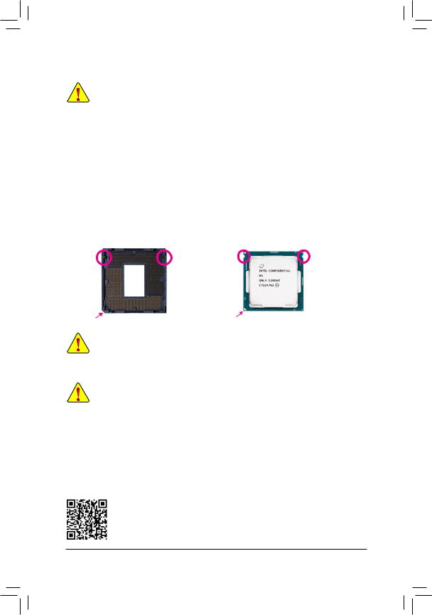
Installing the CPU
Locate the alignment keys on the motherboard CPU socket and the notches on the CPU.
|
LGA1151 CPU Socket |
LGA1151 CPU |
||
|
Alignment Key |
Alignment Key |
Notch |
Notch |
|
Pin One Corner of the CPU Socket |
Triangle Pin One Marking on the CPU |
Do not remove the CPU socket cover before inserting the CPU. It may pop off from the load plate automatically during the process of re-engaging the lever after you insert the CPU.
1-4 Installing the Memory
Read the following guidelines before you begin to install the memory:
•• Make sure that the motherboard supports the memory. It is recommended that memory of the same capacity, brand, speed, and chips be used.
(Go to GIGABYTE’s website for the latest supported memory speeds and memory modules.)
•• Always turn off the computer and unplug the power cord from the power outlet before installing the memory to prevent hardware damage.
•• Memory modules have a foolproof design. A memory module can be installed in only one direction. If you are unable to insert the memory, switch the direction.
Dual Channel Memory Configuration
This motherboard provides four memory sockets and supports Dual Channel Technology. After the memory is installed, the BIOS will automatically detect the specifications and capacity of the memory. Enabling Dual
Channel memory mode will double the original memory bandwidth.
Please visit GIGABYTE’s website for details on hardware installation.
— 9 —

The four memory sockets are divided into two channels and each channel has two memory sockets as following:
Channel A: DDR4_2, DDR4_4Channel B: DDR4_1, DDR4_3
Dual Channel Memory Configurations Table
|
DDR4_4 |
DDR4_2 |
DDR4_3 |
DDR4_1 |
|
|
2 Modules |
— — |
DS/SS |
— — |
DS/SS |
|
DS/SS |
— — |
DS/SS |
— — |
|
|
4 Modules |
DS/SS |
DS/SS |
DS/SS |
DS/SS |
(SS=Single-Sided, DS=Double-Sided, «- -«=No Memory)
Due to CPU limitations, read the following guidelines before installing the memory in Dual Channel mode.
1.Dual Channel mode cannot be enabled if only one memory module is installed.
2.When enabling Dual Channel mode with two or four memory modules, it is recommended that memory of the same capacity, brand, speed, and chips be used.
1-5 Installing an Expansion Card
Read the following guidelines before you begin to install an expansion card:
•• Make sure the motherboard supports the expansion card. Carefully read the manual that came with your expansion card.
•• Always turn off the computer and unplug the power cord from the power outlet before installing an expansion card to prevent hardware damage.
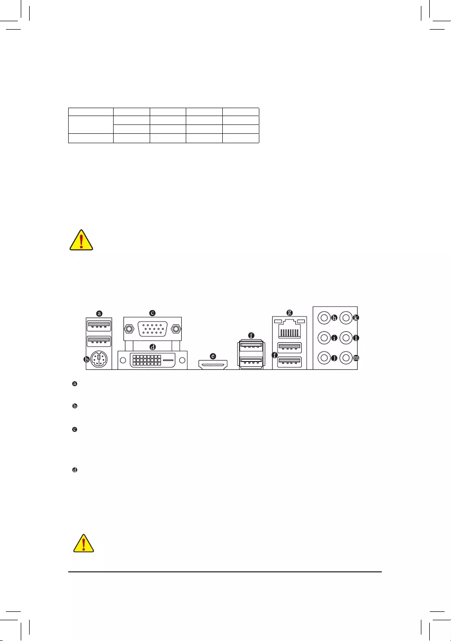
1-6 Back Panel Connectors
USB 2.0/1.1 Port
The USB port supports the USB 2.0/1.1 specification. Use this port for USB devices.
PS/2 Keyboard/Mouse Port
Use this port to connect a PS/2 mouse or keyboard.
D-Sub Port
The D-Sub port supports a 15-pin D-Sub connector and supports a maximum resolution of 1920×1200@60 Hz
(the actual resolutions supported depend on the monitor being used). Connect a monitor that supports D-Sub connection to this port.
DVI-D Port (Note)
The DVI-D port conforms to the DVI-D specification and supports a maximum resolution of 1920×1200@60 Hz
(the actual resolutions supported depend on the monitor being used). Connect a monitor that supports DVI-D connection to this port.
(Note) The DVI-D port does not support D-Sub connection by adapter.
•• When removing the cable connected to a back panel connector, first remove the cable from your device and then remove it from the motherboard.
•• When removing the cable, pull it straight out from the connector. Do not rock it side to side to prevent an electrical short inside the cable connector.
— 10 —
![]()
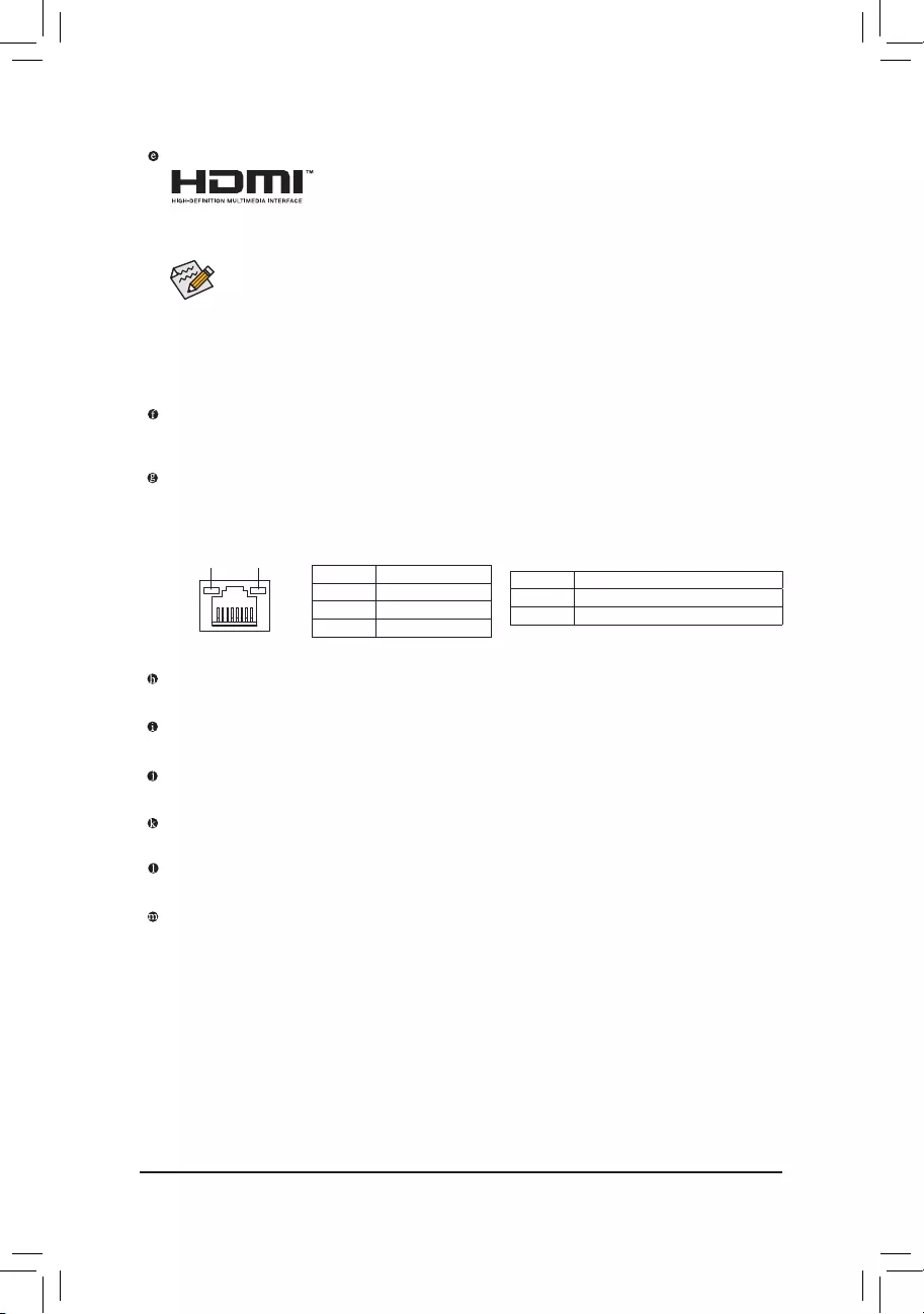
HDMI Port
 The HDMI port supports HDCP 2.2 and Dolby TrueHD and DTS HD Master Audio


 formats. It also supports up to 192KHz/16bit 8-channel LPCM audio output. You can use this port to connect your HDMI-supported monitor. The maximum supported resolution is
4096×2160@30 Hz, but the actual resolutions supported are dependent on the monitor being used.
After installing the HDMI device, make sure to set the default sound playback device to HDMI. (The item name may differ depending on your operating system.)
Triple-Display Configurations for the Onboard Graphics:
Triple-displayconfigurations aresupported after youinstallmotherboarddriversin OS.Onlydual-display configurations are supported during the BIOS Setup or POST process.
USB 3.1 Gen 1 Port
The USB 3.1 Gen 1 port supports the USB 3.1 Gen 1 specification and is compatible to the USB 2.0 specification. Use this port for USB devices.
RJ-45 LAN Port
The Gigabit Ethernet LAN port provides Internet connection at up to 1 Gbps data rate. The following describes the states of the LAN port LEDs.
|
Connection/ |
Connection/Speed LED: |
Activity LED: |
|||||||||||||||||
|
Speed LED |
Activity LED |
||||||||||||||||||
|
State |
Description |
State |
Description |
||||||||||||||||
|
Orange |
1 Gbps data rate |
Blinking |
Data transmission or receiving is occurring |
||||||||||||||||
|
Green |
100 Mbps data rate |
Off |
No data transmission or receiving is occurring |
||||||||||||||||
|
Off |
10 Mbps data rate |
||||||||||||||||||
|
LAN Port |
|||||||||||||||||||
Center/Subwoofer Speaker Out (Orange)
Use this audio jack to connect center/subwoofer speakers.
Rear Speaker Out (Black)
Use this audio jack to connect rear speakers.
Side Speaker Out (Gray)
Use this audio jack to connect side speakers.
Line In (Blue)
The line in jack. Use this audio jack for line in devices such as an optical drive, walkman, etc.
Line Out/Front Speaker Out (Green)
The line out jack.
Mic In (Pink)
The line out jack.
— 11 —
Audio Jack Configurations:
|
Jack |
Headphone/ |
4-channel |
5.1-channel |
7.1-channel |
|
|
2-channel |
|||||
|
Center/Subwoofer Speaker Out |
a |
a |
|||
|
Rear Speaker Out |
a |
a |
a |
||
|
Side Speaker Out |
a |
||||
|
Line In |
|||||
|
Line Out/Front Speaker Out |
a |
a |
a |
a |
|
|
Mic In |
|||||
Please visit GIGABYTE’s website for details on configuring the audio software.
— 12 —
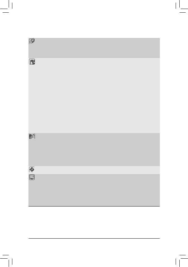
1-7 Internal Connectors
|
4 |
1 |
3 |
|||||||
|
2 |
|||||||
|
4 |
|||||||
|
11 |
|||||||
|
7 |
16 |
||||||
|
6 |
|||||||
|
18 |
|||||||
|
10 |
4 |
||||||
|
19 |
|||||||
|
9 |
13 |
14 |
5 |
7 |
12 |
15 17 |
8 |
|
1) |
ATX_12V_2X4 |
11) |
F_USB30 |
|
2) |
ATX |
12) |
F_USB1/F_USB2 |
|
3) |
CPU_FAN |
13) |
LPT |
|
4) |
SYS_FAN1/2/3 |
14) |
COM |
|
5) |
LED_C |
15) |
TPM |
|
6) |
SATA3 0/1/2/3/4/5 |
16) |
THB_C |
|
7) |
M2M/M2P |
17) |
CLR_CMOS |
|
|
F_PANEL |
18) |
BAT |
|
9) |
F_AUDIO |
19) |
CPU/DRAM/VGA/BOOT |
|
10) |
SPDIF_O |
Read the following guidelines before connecting external devices:
•• First make sure your devices are compliant with the connectors you wish to connect.
•• Before installing the devices, be sure to turn off the devices and your computer. Unplug the power cord from the power outlet to prevent damage to the devices.
•• After installing the device and before turning on the computer, make sure the device cable has been securely attached to the connector on the motherboard.
— 13 —
1/2) ATX_12V_2X4/ATX (2×4 12V Power Connector and 2×12 Main Power Connector)
With the use of the power connector, the power supply can supply enough stable power to all the components on the motherboard. Before connecting the power connector, first make sure the power supply is turned off and all devices are properly installed. The power connector possesses a foolproof design. Connect the power supply cable to the power connector in the correct orientation.
The 12V power connector mainly supplies power to the CPU. If the 12V power connector is not connected, the computer will not start.
To meet expansion requirements, it is recommended that a power supply that can withstand high power consumption be used (500W or greater). If a power supply is used that does not provide the required power, the result can lead to an unstable or unbootable system.
|
ATX_12V_2X4: |
||||||
|
Pin No. |
Definition |
Pin No. |
Definition |
|||
|
5 |
8 |
1 |
GND (Only for 2×4-pin 12V) |
5 |
+12V (Only for 2×4-pin 12V) |
|
|
1 |
4 |
2 |
GND (Only for 2×4-pin 12V) |
6 |
+12V (Only for 2×4-pin 12V) |
|
|
ATX_12V_2X4 |
3 |
GND |
7 |
+12V |
||
|
4 |
GND |
8 |
+12V |
|||
|
ATX: |
||||||
|
12 |
24 |
Pin No. |
Definition |
Pin No. |
Definition |
|
|
1 |
3.3V |
13 |
3.3V |
|||
|
2 |
3.3V |
14 |
-12V |
|||
|
3 |
GND |
15 |
GND |
|||
|
4 |
+5V |
16 |
PS_ON (soft On/Off) |
|||
|
5 |
GND |
17 |
GND |
|||
|
6 |
+5V |
18 |
GND |
|||
|
7 |
GND |
19 |
GND |
|||
|
8 |
Power Good |
20 |
NC |
|||
|
9 |
5VSB (stand by +5V) |
21 |
+5V |
|||
|
10 |
+12V |
22 |
+5V |
|||
|
11 |
+12V (Only for 2×12-pin |
23 |
+5V (Only for 2×12-pin ATX) |
|||
|
1 |
13 |
12 |
ATX) |
24 |
GND (Only for 2×12-pin ATX) |
|
|
3.3V (Only for 2×12-pin ATX) |
ATX
3/4) CPU_FAN/SYS_FAN1/2/3 (Fan Headers)
All fan headers on this motherboard are 4-pin. Most fan headers possess a foolproof insertion design. When connecting a fan cable, be sure to connect it in the correct orientation (the black connector wire is the ground wire). The speed control function requires the use of a fan with fan speed control design. For optimum heat dissipation, it is recommended that a system fan be installed inside the chassis.
|
Pin No. |
Definition |
||||||||
|
1 |
1 |
GND |
|||||||
|
1 |
2 |
Voltage Speed Control |
|||||||
|
CPU_FAN/SYS_FAN1 |
SYS_FAN2/SYS_FAN3 |
3 |
Sense |
||||||
|
4 |
PWM Speed Control |
•• Be sure to connect fan cables to the fan headers to prevent your CPU and system from overheating. Overheating may result in damage to the CPU or the system may hang.
•• Thesefanheadersarenotconfigurationjumperblocks.Donotplaceajumpercapontheheaders.
— 14 —
5)LED_C (RGB LED Strip Header)
The header can be used to connect a standard 5050 RGB LED strip (12V/G/R/B), with maximum power rating of 2A (12V) and maximum length of 2m.
1
RGB
LED Strip
1 
12V
|
Pin No. |
Definition |
|
1 |
12V |
|
2 |
G |
|
3 |
R |
|
4 |
B |
Connect your RGB LED strip to the header. The power pin (marked with a triangle on the plug) of the LED strip must be connected to Pin 1 (12V) of this header. Incorrect connection may lead to the damage of the LED strip.
For how to turn on/off the lights of the LED strip, refer to the instructions in Chapter 2, «BIOS Setup,» «Peripherals.»
Before installing the devices, be sure to turn off the devices and your computer. Unplug the power cord from the power outlet to prevent damage to the devices.
6)SATA3 0/1/2/3/4/5 (SATA 6Gb/s Connectors)
The SATA connectors conform to SATA 6Gb/s standard and are compatible with SATA 3Gb/s and SATA 1.5Gb/s standard. Each SATA connector supports a single SATA device. The Intel® ChipsetsupportsRAID0, RAID 1, RAID 5, and RAID 10. Refer to Chapter 3, «Configuring a RAID Set,» for instructions on configuring a RAID array.
|
SATA3 |
Pin No. |
Definition |
||||||||||
|
7 |
1 |
1 |
GND |
|||||||||
|
3 |
1 |
|||||||||||
|
7 |
1 |
2 |
0 |
2 |
TXP |
|||||||
|
3 |
TXN |
|||||||||||
|
1 |
4 |
GND |
||||||||||
|
5 |
RXN |
|||||||||||
|
6 |
RXP |
|||||||||||
|
SATA3 |
7 |
GND |
||||||||||
|
4 |
||||||||||||
|
5 |
||||||||||||
7
To enable hot-plugging for the SATA ports, refer to Chapter 2, «BIOS Setup,» «PeripheralsSATA And RST Configuration,» for more information.
— 15 —

To reduce the impacts on global warming, the packaging materials of this product
are recyclable and reusable. GIGABYTE works with you to protect the environment.
For more product details, please visit GIGABYTE’s website.
B365 HD3
User’s Manual
Rev. 1002
Copyright
© 2019 GIGA-BYTE TECHNOLOGY CO., LTD. All rights reserved.
The trademarks mentioned in this manual are legally registered to their respective owners.
Disclaimer
Information in this manual is protected by copyright laws and is the property of GIGABYTE.
Changes to the specications and features in this manual may be made by GIGABYTE without prior notice.
No part of this manual may be reproduced, copied, translated, transmitted, or published in any form or
by any means without GIGABYTE’s prior written permission.
In order to assist in the use of this product, carefully read the User’s Manual.
For product-related information, check on our website at: https://www.gigabyte.com
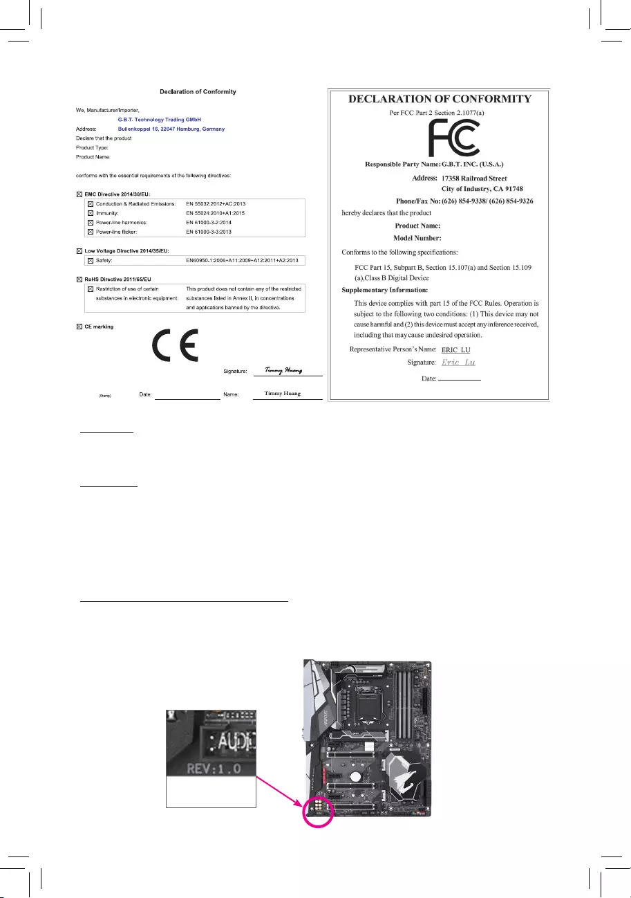
Identifying Your Motherboard Revision
The revision number on your motherboard looks like this: «REV: X.X.» For example, «REV: 1.0″ means
the revision of the motherboard is 1.0. Check your motherboard revision before updating motherboard
BIOS, drivers, or when looking for technical information.
Example:
Motherboard
B365 HD3
Jul. 26, 2019
Jul. 26, 2019
Motherboard
B365 HD3

— 3 —
Table of Contents
B365 HD3 Motherboard Layout …………………………………………………………………………… 4
Chapter 1 Hardware Installation ………………………………………………………………………….5
1-1 Installation Precautions ………………………………………………………………………… 5
1-2 ProductSpecications ………………………………………………………………………….. 6
1-3 Installing the CPU ……………………………………………………………………………….. 9
1-4 Installing the Memory …………………………………………………………………………… 9
1-5 Installing an Expansion Card ………………………………………………………………. 10
1-6 Back Panel Connectors ………………………………………………………………………. 10
1-7 Internal Connectors ……………………………………………………………………………. 13
Chapter 2 BIOS Setup ……………………………………………………………………………………..21
2-1 Startup Screen ………………………………………………………………………………….. 21
2-2 The Main Menu …………………………………………………………………………………. 22
2-3 M.I.T. ……………………………………………………………………………………………….. 23
2-4 System …………………………………………………………………………………………….. 29
2-5 BIOS ………………………………………………………………………………………………… 30
2-6 Peripherals ……………………………………………………………………………………….. 33
2-7 Chipset …………………………………………………………………………………………….. 36
2-8 Power ………………………………………………………………………………………………. 37
2-9 Save & Exit ……………………………………………………………………………………….. 39
Chapter 3 Appendix …………………………………………………………………………………………40
3-1 ConguringaRAIDSet ………………………………………………………………………. 40
3-2 Installing an Intel® Optane™ Memory …………………………………………………….. 42
3-3 Drivers Installation ……………………………………………………………………………… 44
RegulatoryStatements …………………………………………………………………………………. 45
Contact Us …………………………………………………………………………………………………. 47
— 4 —
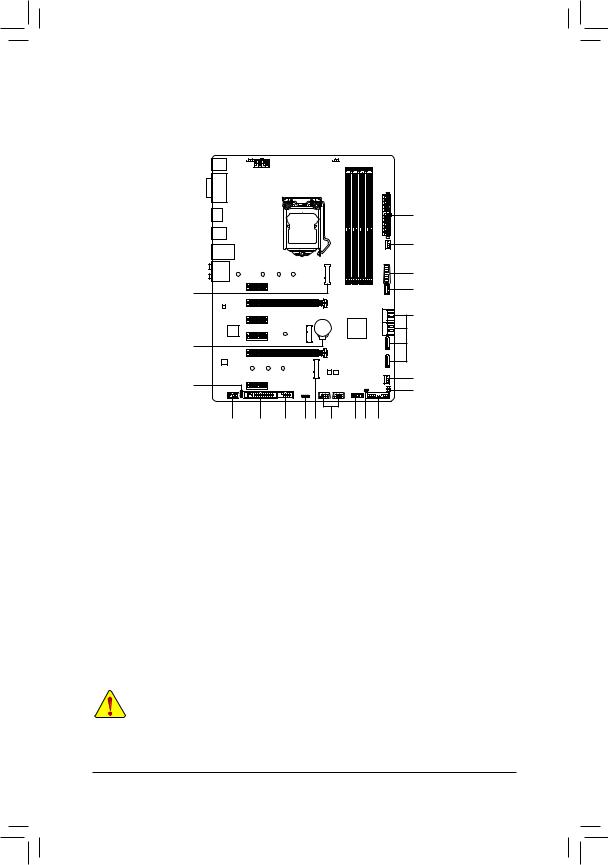
B365 HD3 Motherboard Layout
* The box contents above are for reference only and the actual items shall depend on the product package you obtain.
The box contents are subject to change without notice.
KB_MS_USB
DVI
D_SUB
HDMI
R_USB30
USB30_LAN
LGA1151
ATX
AUDIO
DDR4_4
DDR4_2
DDR4_3
DDR4_1
ATX_12V_2X4
Intel® B365
CLR_CMOS
M_BIOS
B_BIOS
PCIEX1_1
PCIEX4
PCIEX16
PCIEX1_2
PCIEX1_4
PCIEX1_3
F_USB30
M2M
M2P
M2_WIFI
CODEC
B365 HD3
F_PANELTPM
F_USB1F_USB2
LED_C
SPDIF_O
F_AUDIO
COMLPT
SYS_FAN3
SYS_FAN1
SYS_FAN2
THB_C
CPU_FAN
iTE®
Super I/O
42
42
30
60
60
80
80
110
BAT
Realtek®
GbE LAN
CPU DRAM
VGA BOOT
SATA3 3 1
2 0
SATA3 5 4
Box Contents
5B365 HD3 motherboard 5Two SATA cables
5Motherboard driver disc 5I/O Shield
5User’s Manual

Chapter 1 Hardware Installation
1-1 Installation Precautions
The motherboard contains numerous delicate electronic circuits and components which can become
damaged as a result of electrostatic discharge (ESD). Prior to installation, carefully read the user’s
manual and follow these procedures:
•Prior to installation, make sure the chassis is suitable for the motherboard.
•Prior to installation, do not remove or break motherboard S/N (Serial Number) sticker or
warranty sticker provided by your dealer. These stickers are required for warranty validation.
•Always remove the AC power by unplugging the power cord from the power outlet before
installing or removing the motherboard or other hardware components.
•When connecting hardware components to the internal connectors on the motherboard, make
sure they are connected tightly and securely.
•When handling the motherboard, avoid touching any metal leads or connectors.
•It is best to wear an electrostatic discharge (ESD) wrist strap when handling electronic
components such as a motherboard, CPU or memory. If you do not have an ESD wrist strap,
keepyourhandsdryandrsttouchametalobjecttoeliminatestaticelectricity.
•Prior to installing the motherboard, please have it on top of an antistatic pad or within an
electrostatic shielding container.
•Before connecting or unplugging the power supply cable from the motherboard, make sure
the power supply has been turned off.
•Before turning on the power, make sure the power supply voltage has been set according to
the local voltage standard.
•Before using the product, please verify that all cables and power connectors of your hardware
components are connected.
•To prevent damage to the motherboard, do not allow screws to come in contact with the
motherboard circuit or its components.
•Make sure there are no leftover screws or metal components placed on the motherboard or
within the computer casing.
•Do not place the computer system on an uneven surface.
•Do not place the computer system in a high-temperature or wet environment.
•Turning on the computer power during the installation process can lead to damage to system
components as well as physical harm to the user.
•If you are uncertain about any installation steps or have a problem related to the use of the
product,pleaseconsultacertiedcomputertechnician.
•If you use an adapter, extension power cable, or power strip, ensure to consult with its installation
and/or grounding instructions.
— 5 —
1-2 ProductSpecications
CPU Support for 9th and 8th Generation Intel® Core™ i9 processors/Intel® Core™ i7
processors/Intel® Core™ i5 processors/Intel® Core™ i3 processors/Intel® Pentium®
processors/Intel® Celeron® processors in the LGA1151 package
(Go to GIGABYTE’s website for the latest CPU support list.)
L3 cache varies with CPU
Chipset Intel® B365 Express Chipset
Memory 4xDDR4DIMMsocketssupportingupto64GBofsystemmemory
Dual channel memory architecture
SupportforDDR42666/2400/2133MHzmemorymodules
SupportforECCUn-bufferedDIMM 1Rx8/2Rx8 memory modules (operate in
non-ECC mode)
Supportfornon-ECCUn-bufferedDIMM1Rx8/2Rx8/1Rx16memorymodules
SupportforExtremeMemoryProle(XMP)memorymodules
* Tosupport2666MHzorXMPmemory,youmustinstalla9thor8thGenerationIntel®
Core™ i9/i7/i5 processor.
(Go to GIGABYTE’s website for the latest supported memory speeds and memory
modules.)
Onboard
Graphics
Integrated Graphics Processor-Intel® HD Graphics support:
- 1xD-Subport,supportingamaximumresolutionof1920×1200@60Hz
- 1xDVI-Dport,supportingamaximumresolutionof1920×1200@60Hz
* The DVI-D port does not support D-Sub connection by adapter.
- 1xHDMIport,supportingamaximumresolutionof4096×2160@30Hz
* Support for HDMI 1.4 version and HDCP 2.2.
— Support for up to 3 displays at the same time
Maximum shared memory of 1 GB
Audio Realtek® ALC892 codec
HighDenitionAudio
2/4/5.1/7.1-channel
Support for S/PDIF Out
LAN Realtek® GbE LAN chip (10/100/1000 Mbit)
Expansion Slots 1 x PCI Express x16 slot, running at x16 (PCIEX16)
* For optimum performance, if only one PCI Express graphics card is to be installed,
be sure to install it in the PCIEX16 slot.
1 x PCI Express x16 slot, running at x4 (PCIEX4)
4 x PCI Express x1 slots
(All of the PCI Express slots conform to PCI Express 3.0 standard.)
1 x M.2 Socket 1 connector for the wireless communication module (M2_WIFI)
Multi-Graphics
Technology Support for AMD Quad-GPU CrossFire™ and 2-Way AMD CrossFire™ technologies
Storage Interface Chipset:
— 1 x M.2 connector (Socket 3, M key, type 2242/2260/2280/22110 PCIe x4/
x2 SSD support) (M2M)
— 1 x M.2 connector (Socket 3, M key, type 2242/2260/2280 SATA and PCIe
x2 SSD support) (M2P)
— 6 x SATA 6Gb/s connectors
- SupportforRAID0,RAID1,RAID5,andRAID10
* Referto»1-7InternalConnectors,»fortheinstallationnoticesfortheM.2andSATA
connectors.
Intel® Optane™MemoryReady
— 6 —
USB Chipset:
— 6 x USB 3.1 Gen 1 ports (4 ports on the back panel, 2 ports available through
the internal USB header)
— 6 x USB 2.0/1.1 ports (2 ports on the back panel, 4 ports available through
the internal USB headers)
Internal
Connectors
1 x 24-pin ATX main power connector
1 x 8-pin ATX 12V power connector
1 x CPU fan header
3 x system fan headers
1xRGBLEDstripheader
6 x SATA 6Gb/s connectors
2 x M.2 Socket 3 connectors
1 x front panel header
1 x front panel audio header
1 x S/PDIF Out header
1 x USB 3.1 Gen 1 header
2 x USB 2.0/1.1 headers
1 x Thunderbolt™ add-in card connector
1 x Trusted Platform Module (TPM) header (2×6 pin, for the GC-TPM2.0_S
module only)
1 x parallel port header
1 x serial port header
1 x Clear CMOS jumper
Back Panel
Connectors
1 x PS/2 keyboard/mouse port
1 x D-Sub port
1 x DVI-D port
1 x HDMI port
4 x USB 3.1 Gen 1 ports
2 x USB 2.0/1.1 ports
1xRJ-45port
6 x audio jacks
I/O Controller iTE® I/O Controller Chip
Hardware
Monitor
Voltage detection
Temperature detection
Fan speed detection
Overheating warning
Fan fail warning
Fan speed control
* Whether the fan speed control function is supported will depend on the cooler you
install.
— 7 —
BIOS 2x128Mbitash
Use of licensed AMI UEFI BIOS
Support for DualBIOS™
PnP 1.0a, DMI 2.7, WfM 2.0, SM BIOS 2.7, ACPI 5.0
Unique Features Support for APP Center
* Available applications in APP Center may vary by motherboard model. Supported
functionsofeachapplicationmayalsovarydependingonmotherboardspecications.
— @BIOS
— AutoGreen
— Cloud Station
— EasyTune
- EasyRAID
— Fast Boot
— Game Boost
— ON/OFF Charge
— Platform Power Management
- RGBFusion
— Smart Backup
— Smart Keyboard
— Smart HUD
— Smart Survey
— System Information Viewer
— USB Blocker
Support for Q-Flash
Support for Xpress Install
Bundled
Software
Norton® Internet Security (OEM version)
Realtek® 8118 Gaming LAN Bandwidth Control Utility
Operating
System Support for Windows 10 64-bit
Form Factor ATX Form Factor; 30.5cm x 22.5cm
* GIGABYTEreservestherighttomakeanychangestotheproductspecicationsandproduct-relatedinformationwithout
prior notice.
Please visit GIGABYTE’s website
for support lists of CPU, memory
modules, SSDs, and M.2 devices.
Please visit the SupportUtility List
page on GIGABYTE’s website to
download the latest version of apps.
— 8 —

1-3 Installing the CPU
ReadthefollowingguidelinesbeforeyoubegintoinstalltheCPU:
•Make sure that the motherboard supports the CPU.
(Go to GIGABYTE’s website for the latest CPU support list.)
•Always turn off the computer and unplug the power cord from the power outlet before installing the
CPU to prevent hardware damage.
•Locate the pin one of the CPU. The CPU cannot be inserted if oriented incorrectly. (Or you may
locate the notches on both sides of the CPU and alignment keys on the CPU socket.)
•Apply an even and thin layer of thermal grease on the surface of the CPU.
•Do not turn on the computer if the CPU cooler is not installed, otherwise overheating and damage
of the CPU may occur.
•SettheCPUhostfrequencyinaccordancewiththeCPUspecications.Itisnotrecommended
thatthesystembusfrequencybesetbeyondhardwarespecicationssinceitdoesnotmeetthe
standard requirements for the peripherals. If you wish to set the frequency beyond the standard
specications,pleasedosoaccordingtoyourhardwarespecicationsincludingtheCPU,graphics
card, memory, hard drive, etc.
DualChannelMemoryConguration
This motherboard provides four memory sockets and supports Dual Channel Technology. After the memory
isinstalled,theBIOSwillautomaticallydetectthespecicationsandcapacityofthememory.EnablingDual
Channel memory mode will double the original memory bandwidth.
Please visit GIGABYTE’s website for details on hardware installation.
Installing the CPU
Locate the alignment keys on the motherboard CPU socket and the notches on the CPU.
Do not remove the CPU socket cover before inserting the CPU. It may pop off from the load
plate automatically during the process of re-engaging the lever after you insert the CPU.
Triangle Pin One Marking on the CPU
NotchNotch
LGA1151 CPU
Alignment KeyAlignment Key
LGA1151 CPU Socket
Pin One Corner of the CPU Socket
1-4 Installing the Memory
Readthefollowingguidelinesbeforeyoubegintoinstallthememory:
•Make sure that the motherboard supports the memory. It is recommended that memory of the same
capacity, brand, speed, and chips be used.
(Go to GIGABYTE’s website for the latest supported memory speeds and memory modules.)
•Always turn off the computer and unplug the power cord from the power outlet before installing the
memory to prevent hardware damage.
•Memory modules have a foolproof design. A memory module can be installed in only one direction.
If you are unable to insert the memory, switch the direction.
— 9 —
The four memory sockets are divided into two channels and each channel has two memory sockets as following:
ChannelA:DDR4_2,DDR4_4
ChannelB:DDR4_1,DDR4_3
DualChannelMemoryCongurationsTable
DDR4_4 DDR4_2 DDR4_3 DDR4_1
2 Modules — — DS/SS — — DS/SS
DS/SS — — DS/SS — —
4 Modules DS/SS DS/SS DS/SS DS/SS
(SS=Single-Sided,DS=Double-Sided,»--«=NoMemory)
Due to CPU limitations, read the following guidelines before installing the memory in Dual Channel mode.
1. Dual Channel mode cannot be enabled if only one memory module is installed.
2. When enabling Dual Channel mode with two or four memory modules, it is recommended that memory
of the same capacity, brand, speed, and chips be used.
1-5 Installing an Expansion Card
Readthefollowingguidelinesbeforeyoubegintoinstallanexpansioncard:
•Make sure the motherboard supports the expansion card. Carefully read the manual that came
with your expansion card.
•Always turn off the computer and unplug the power cord from the power outlet before installing an
expansion card to prevent hardware damage.
1-6 Back Panel Connectors
USB 2.0/1.1 Port
TheUSBportsupportstheUSB2.0/1.1specication.UsethisportforUSBdevices.
PS/2 Keyboard/Mouse Port
Use this port to connect a PS/2 mouse or keyboard.
D-Sub Port
TheD-Subportsupportsa15-pinD-Subconnectorandsupportsamaximumresolutionof1920×1200@60Hz
(the actual resolutions supported depend on the monitor being used). Connect a monitor that supports
D-Sub connection to this port.
DVI-D Port (Note)
TheDVI-DportconformstotheDVI-Dspecicationandsupportsamaximumresolutionof1920×1200@60Hz
(the actual resolutions supported depend on the monitor being used). Connect a monitor that supports
DVI-D connection to this port.
(Note) The DVI-D port does not support D-Sub connection by adapter.
•Whenremovingthecableconnectedtoabackpanelconnector,rstremovethecablefromyour
device and then remove it from the motherboard.
•When removing the cable, pull it straight out from the connector. Do not rock it side to side to
prevent an electrical short inside the cable connector.
— 10 —
HDMI Port
The HDMI port supports HDCP 2.2 and Dolby TrueHD and DTS HD Master Audio
formats.Italsosupportsupto192KHz/16bit8—channelLPCMaudiooutput.You
can use this port to connect your HDMI—supported monitor. The maximum supported resolution is
4096x2160@30Hz,buttheactualresolutionssupportedaredependentonthemonitorbeingused.
USB 3.1 Gen 1 Port
TheUSB3.1Gen1portsupportstheUSB3.1Gen1specicationandiscompatibletotheUSB2.0
specication.UsethisportforUSBdevices.
RJ-45 LAN Port
The Gigabit Ethernet LAN port provides Internet connection at up to 1 Gbps data rate. The following
describes the states of the LAN port LEDs.
After installing the HDMI device, make sure to set the default sound playback device to HDMI.
(The item name may differ depending on your operating system.)
Center/Subwoofer Speaker Out (Orange)
Use this audio jack to connect center/subwoofer speakers.
Rear Speaker Out (Black)
Use this audio jack to connect rear speakers.
Side Speaker Out (Gray)
Use this audio jack to connect side speakers.
Line In (Blue)
The line in jack. Use this audio jack for line in devices such as an optical drive, walkman, etc.
Line Out/Front Speaker Out (Green)
The line out jack.
Mic In (Pink)
The line out jack.
Triple-DisplayCongurationsfortheOnboardGraphics:
Triple—displaycongurationsaresupportedafteryouinstallmotherboarddriversinOS.Onlydual—display
congurationsaresupportedduringtheBIOSSetuporPOSTprocess.
Activity LED
Connection/
Speed LED
LAN Port
Activity LED:
Connection/Speed LED:
State Description
Orange 1 Gbps data rate
Green 100 Mbps data rate
Off 10 Mbps data rate
State Description
Blinking Data transmission or receiving is occurring
Off No data transmission or receiving is occurring
— 11 —
PleasevisitGIGABYTE’swebsitefordetailsonconguringtheaudiosoftware.
AudioJackCongurations:
Jack Headphone/
2-channel 4-channel 5.1-channel 7.1-channel
Center/Subwoofer Speaker Out a a
RearSpeakerOut a a a
Side Speaker Out a
Line In
Line Out/Front Speaker Out a a a a
Mic In
— 12 —
1-7 Internal Connectors
Readthefollowingguidelinesbeforeconnectingexternaldevices:
•First make sure your devices are compliant with the connectors you wish to connect.
•Before installing the devices, be sure to turn off the devices and your computer. Unplug the power
cord from the power outlet to prevent damage to the devices.
•After installing the device and before turning on the computer, make sure the device cable has
been securely attached to the connector on the motherboard.
1) ATX_12V_2X4
2) ATX
3) CPU_FAN
4) SYS_FAN1/2/3
5) LED_C
6) SATA3 0/1/2/3/4/5
7) M2M/M2P
 F_PANEL
9) F_AUDIO
10) SPDIF_O
11) F_USB30
12) F_USB1/F_USB2
13) LPT
14) COM
15) TPM
16) THB_C
17) CLR_CMOS
18) BAT
19) CPU/DRAM/VGA/BOOT
817
4
2
6
11
16
59 13
1
4
14
4
19
18
10
7
12 157
3
— 13 —
3/4) CPU_FAN/SYS_FAN1/2/3 (Fan Headers)
All fan headers on this motherboard are 4-pin. Most fan headers possess a foolproof insertion design.
When connecting a fan cable, be sure to connect it in the correct orientation (the black connector wire is
the ground wire). The speed control function requires the use of a fan with fan speed control design. For
optimum heat dissipation, it is recommended that a system fan be installed inside the chassis.
•Be sure to connect fan cables to the fan headers to prevent your CPU and system from
overheating. Overheating may result in damage to the CPU or the system may hang.
•Thesefanheadersarenotcongurationjumperblocks.Donotplaceajumpercapontheheaders.
CPU_FAN/SYS_FAN1
1
SYS_FAN2/SYS_FAN3
1
Pin No. Denition
1 GND
2 Voltage Speed Control
3 Sense
4 PWM Speed Control
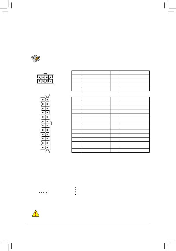
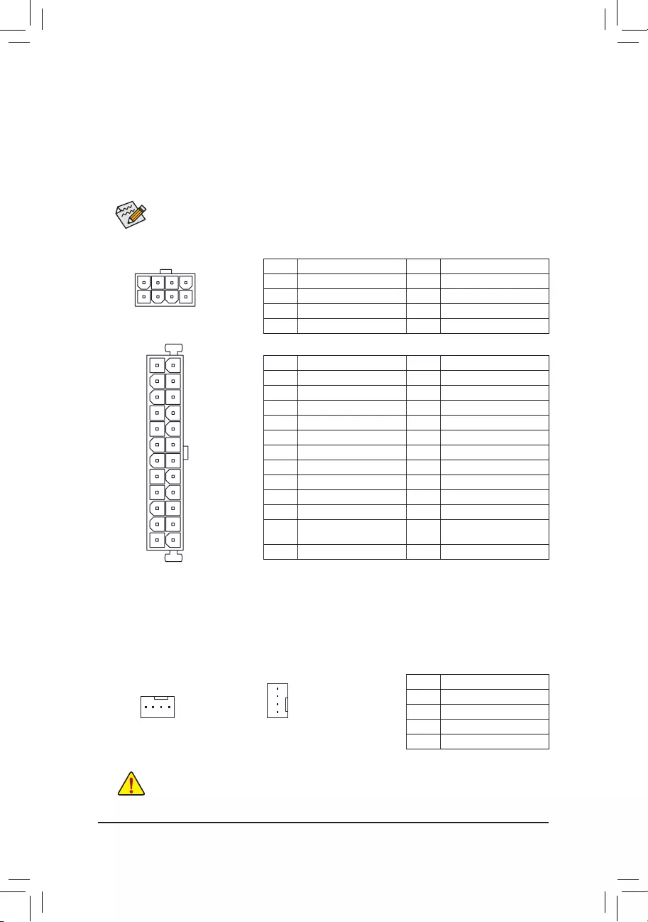
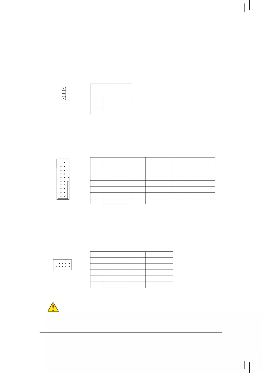
1/2) ATX_12V_2X4/ATX (2×4 12V Power Connector and 2×12 Main Power Connector)
With the use of the power connector, the power supply can supply enough stable power to all the components
onthemotherboard.Beforeconnectingthepowerconnector,rstmakesurethepowersupplyisturned
off and all devices are properly installed. The power connector possesses a foolproof design. Connect the
power supply cable to the power connector in the correct orientation.
The 12V power connector mainly supplies power to the CPU. If the 12V power connector is not connected,
the computer will not start.
To meet expansion requirements, it is recommended that a power supply that can withstand high
power consumption be used (500W or greater). If a power supply is used that does not provide the
required power, the result can lead to an unstable or unbootable system.
131
24
12
ATX
ATX:
Pin No. Denition Pin No. Denition
1 3.3V 13 3.3V
2 3.3V 14 -12V
3 GND 15 GND
4 +5V 16 PS_ON (soft On/Off)
5 GND 17 GND
6 +5V 18 GND
7 GND 19 GND
8 Power Good 20 NC
9 5VSB (stand by +5V) 21 +5V
10 +12V 22 +5V
11 +12V (Only for 2×12-pin
ATX)
23 +5V (Only for 2×12-pin ATX)
12 3.3V (Only for 2×12-pin ATX) 24 GND (Only for 2×12-pin ATX)
ATX_12V_2X4:
Pin No. Denition Pin No. Denition
1 GND (Only for 2×4-pin 12V) 5 +12V (Only for 2×4-pin 12V)
2 GND (Only for 2×4-pin 12V) 6 +12V (Only for 2×4-pin 12V)
3 GND 7 +12V
4 GND 8 +12V
ATX_12V_2X4
41
85
— 14 —
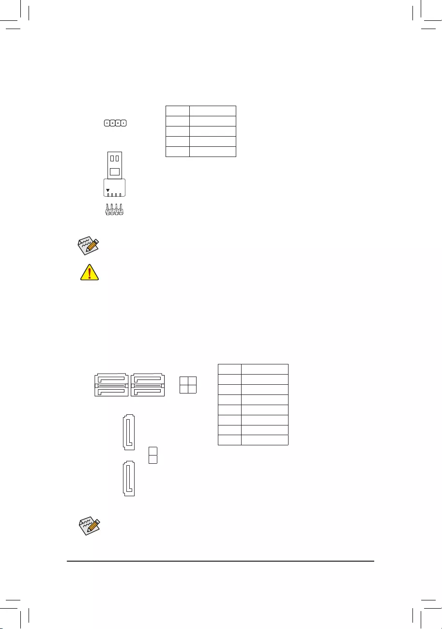
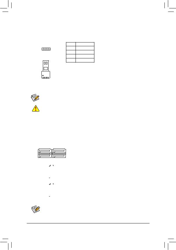
5) LED_C (RGB LED Strip Header)
Theheadercanbeusedtoconnectastandard5050RGBLEDstrip(12V/G/R/B),withmaximumpower
rating of 2A (12V) and maximum length of 2m.
Pin No. Denition
1 12V
2 G
3R
4 B
Before installing the devices, be sure to turn off the devices and your computer. Unplug the power
cord from the power outlet to prevent damage to the devices.
Forhowtoturnon/offthelightsoftheLEDstrip, refer to the instructions in Chapter2,«BIOS
Setup,»»Peripherals.»
1
ConnectyourRGBLEDstriptotheheader.Thepowerpin(markedwitha
triangle on the plug) of the LED strip must be connected to Pin 1 (12V) of
this header. Incorrect connection may lead to the damage of the LED strip.
RGB
LED Strip
1
12V
6) SATA3 0/1/2/3/4/5 (SATA 6Gb/s Connectors)
The SATA connectors conform to SATA 6Gb/s standard and are compatible with SATA 3Gb/s and SATA
1.5Gb/s standard. Each SATA connector supports a single SATA device. The Intel®ChipsetsupportsRAID0,
RAID1,RAID5,andRAID10.RefertoChapter3,»ConguringaRAIDSet,»forinstructionsonconguring
aRAIDarray.
Pin No. Denition
1 GND
2 TXP
3 TXN
4 GND
5RXN
6RXP
7 GND
Toenablehot-pluggingfortheSATAports,refertoChapter2,«BIOSSetup,»«PeripheralsSATA
AndRSTConguration,»formoreinformation.
1
1
SATA3
SATA3
3 1
2 0
4
5
7
7
1
7
— 15 —
7) M2M/M2P (M.2 Socket 3 Connectors)
TheM.2connectorssupportM.2SATASSDsorM.2PCIeSSDsandsupportRAIDconguration.Please
notethatanM.2PCIeSSDcannotbeusedtocreateaRAIDseteitherwithanM.2SATASSDoraSATA
harddrive.TocreateaRAIDarraywithanM.2PCIeSSD,youmustsetupthecongurationinUEFIBIOS
mode.RefertoChapter3,»ConguringaRAIDSet,»forinstructionsonconguringaRAIDarray.
Follow the steps below to correctly install an M.2 SSD in the M.2 connector.
Step 1:
Use a screw driver to unfasten the screw and standoff from the motherboard. Locate the proper mounting
holefortheM.2SSDtobeinstalledandthenscrewthestandoffrst.
Step 2:
Slide the M.2 SSD into the connector at an angle.
Step 3:
Press the M.2 SSD down and then secure it with the screw.
Select the proper hole for the M.2 SSD to be installed and refasten the screw and standoff.
F_USB30 F_U
B_
F_ F_
_
B
BS_
B
SB_
B
_S
S_
_
B
_U
_
B
S
123
123
123
123
1
1
1
1
BSS
S
_S
SSU
1 2 3 4 5
S3 BSSS
U
__ 3
F_USB3F
S _
S _
S _
SF
B_
B_
F
_0
S
S
_0F
_F
_
_
__B
U
S _S
_ SF_
B
USB0_B
B_ F_USB3
F_USB303
_
_3U
S_
80110 60 42
F_USB30 F_U
B_
F_ F_
_
B
BS_
B
SB_
B
_S
S_
_
B
_U
_
B
S
123
123
123
123
1
1
1
1
BSS
S
_S
SSU
1 2 3 4 5
S3 BSSS
U
__ 3
F_USB3F
S _
S _
S _
SF
B_
B_
F
_0
S
S
_0F
_F
_
_
__B
U
S _S
_ SF_
B
USB0_B
B_ F_USB3
F_USB303
_
_3U
S_
80 60 42
M2M
M2P
InstallationNoticesfortheM.2andSATAConnectors:
The availability of the SATA connectors may be affected by the type of device installed in the M.2 sockets.
TheM2PconnectorsharesbandwidthwiththeSATA30connector.Refertothefollowingtablefordetails.
•M2M:
SATA3 0 SATA3 1 SATA3 2 SATA3 3 SATA3 4 SATA3 5
M.2 PCIe SSD *
a a a a a a
No M.2 SSD Installed a a a a a a
a: Available, r: Not available
* The M2M connector supports only PCIe SSDs.
Connector
Type of
M.2 SSD
•M2P:
SATA3 0 SATA3 1 SATA3 2 SATA3 3 SATA3 4 SATA3 5
M.2 SATA SSD raaaaa
M.2 PCIe SSD*
a a a a a a
No M.2 SSD Installed a a a a a a
a: Available, r: Not available
* The M2P connector supports up to PCIe x2 SSDs only.
Connector
Type of
M.2 SSD
— 16 —
The front panel design may differ by chassis. A front panel module mainly consists of power switch,
reset switch, power LED, hard drive activity LED, speaker and etc. When connecting your chassis
front panel module to this header, make sure the wire assignments and the pin assignments are
matched correctly.
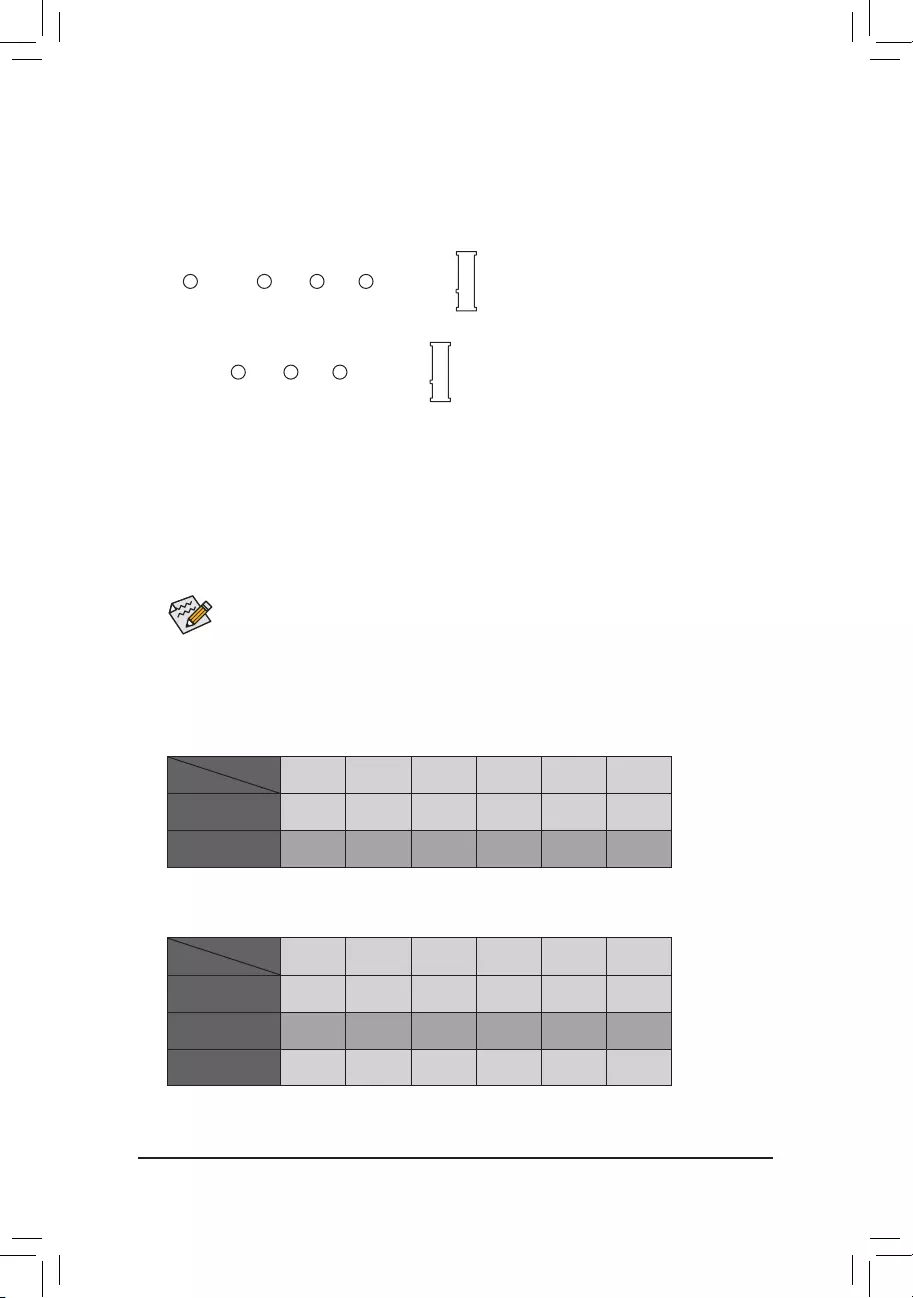
F_PANEL (Front Panel Header)
Connect the power switch, reset switch, speaker, chassis intrusion switch/sensor and system status indicator
on the chassis to this header according to the pin assignments below. Note the positive and negative pins
before connecting the cables.
System Status LED
S0 On
S3/S4/S5 Off
•PW(PowerSwitch,Red):
Connects to the power switch on the chassis front panel. You may
congurethewaytoturnoffyoursystemusingthepowerswitch(refer
toChapter2,»BIOSSetup,»»Power,»formoreinformation).
•SPEAK (Speaker, Orange):
Connects to the speaker on the chassis front panel. The system reports
system startup status by issuing a beep code. One single short beep
will be heard if no problem is detected at system startup.
•PLED/PWR_LED (Power LED, Yellow/Purple):
Connects to the power status indicator
on the chassis front panel. The LED is on
when the system is operating. The LED is
off when the system is in S3/S4 sleep state
or powered off (S5).
•HD (Hard Drive Activity LED, Blue):
Connects to the hard drive activity LED on the chassis front panel. The LED is on when the hard drive
is reading or writing data.
•RES (ResetSwitch,Green):
Connects to the reset switch on the chassis front panel. Press the reset switch to restart the computer
ifthecomputerfreezesandfailstoperformanormalrestart.
•CI (Chassis Intrusion Header, Gray):
Connects to the chassis intrusion switch/sensor on the chassis that can detect if the chassis cover has
been removed. This function requires a chassis with a chassis intrusion switch/sensor.
•NC (Orange): No Connection.
NC
NC
Power LED
1
2
19
20
CI-
CI+
PWR_LED-
PWR_LED+
PLED-
PW-
SPEAK+
SPEAK-
PLED+
PW+
Power LED
HD-
RES+
HD+
RES-
Hard Drive
Activity LED
Reset
Switch Chassis Intrusion
Header
Power Switch Speaker
PWR_LED-
9) F_AUDIO (Front Panel Audio Header)
ThefrontpanelaudioheadersupportsHighDenitionaudio(HD).Youmayconnectyourchassisfront
panel audio module to this header. Make sure the wire assignments of the module connector match the
pin assignments of the motherboard header. Incorrect connection between the module connector and the
motherboard header will make the device unable to work or even damage it.
F_USB30 F_U
B_
F_ F_
_
B
BS_
B
SB_
B
_S
S_
_
B
_U
_
B
S
123
123
123
123
1
1
1
1
BSS
S
_S
SSU
1 2 3 4 5
S3 BSSS
U
__ 3
F_USB3F
S _
S _
S _
SF
B_
B_
F
_0
S
S
_0F
_F
_
_
__B
U
S _S
_ SF_
B
USB0_B
B_ F_USB3
F_USB303
_
_3U
S_
9 1
10 2
Pin No. Denition Pin No. Denition
1 MIC2_L 6 Sense
2 GND 7 FAUDIO_JD
3MIC2_R 8 No Pin
4 NC 9 LINE2_L
5LINE2_R 10 Sense
Some chassis provide a front panel audio module that has separated connectors on each wire
instead of a single plug. For information about connecting the front panel audio module that has
different wire assignments, please contact the chassis manufacturer.
— 17 —
1
F_USB30 F_U
B_
F_ F_
_
B
BS_
B
SB_
B
_S
S_
_
B
_U
_
B
S
123
123
123
123
1
1
1
1
BSS
S
_S
SSU
1 2 3 4 5
S3 BSSS
U
__ 3
F_USB3F
S _
S _
S _
SF
B_
B_
F
_0
S
S
_0F
_F
_
_
__B
U
S _S
_ SF_
B
USB0_B
B_ F_USB3
F_USB303
_
_3U
S_
•Do not plug the IEEE 1394 bracket (2×5-pin) cable into the USB 2.0/1.1 header.
•Prior to installing the USB bracket, be sure to turn off your computer and unplug the power cord
from the power outlet to prevent damage to the USB bracket.
10) SPDIF_O (S/PDIF Out Header)
This header supports digital S/PDIF Out and connects a S/PDIF digital audio cable (provided by expansion
cards) for digital audio output from your motherboard to certain expansion cards like graphics cards and
sound cards. For example, some graphics cards may require you to use a S/PDIF digital audio cable for
digital audio output from your motherboard to your graphics card if you wish to connect an HDMI display
to the graphics card and have digital audio output from the HDMI display at the same time. For information
about connecting the S/PDIF digital audio cable, carefully read the manual for your expansion card.
Pin No. Denition
1 5VDUAL
2 No Pin
3 SPDIFO
4 GND
Pin No. Denition Pin No. Denition Pin No. Denition
1 VBUS 8 D1- 15 SSTX2-
2SSRX1- 9 D1+ 16 GND
3SSRX1+ 10 NC 17 SSRX2+
4 GND 11 D2+ 18 SSRX2-
5 SSTX1- 12 D2- 19 VBUS
6 SSTX1+ 13 GND 20 No Pin
7 GND 14 SSTX2+
11) F_USB30 (USB 3.1 Gen 1 Header)
TheheaderconformstoUSB3.1Gen1andUSB2.0specicationandcanprovidetwoUSBports.For
purchasingtheoptional3.5″frontpanelthatprovidestwoUSB3.1Gen1ports,pleasecontactthelocal
dealer.
F_USB30 F_U
B_
F_ F_
_
B
BS_
B
SB_
B
_S
S_
_
B
_U
_
B
S
123
123
123
123
1
1
1
1
BSS
S
_S
SSU
1 2 3 4 5
S3 BSSS
U
__ 3
F_USB3F
S _
S _
S _
SF
B_
B_
F
_0
S
S
_0F
_F
_
_
__B
U
S _S
_ SF_
B
USB0_B
B_ F_USB3
F_USB303
_
_3U
S_
10
20 1
11
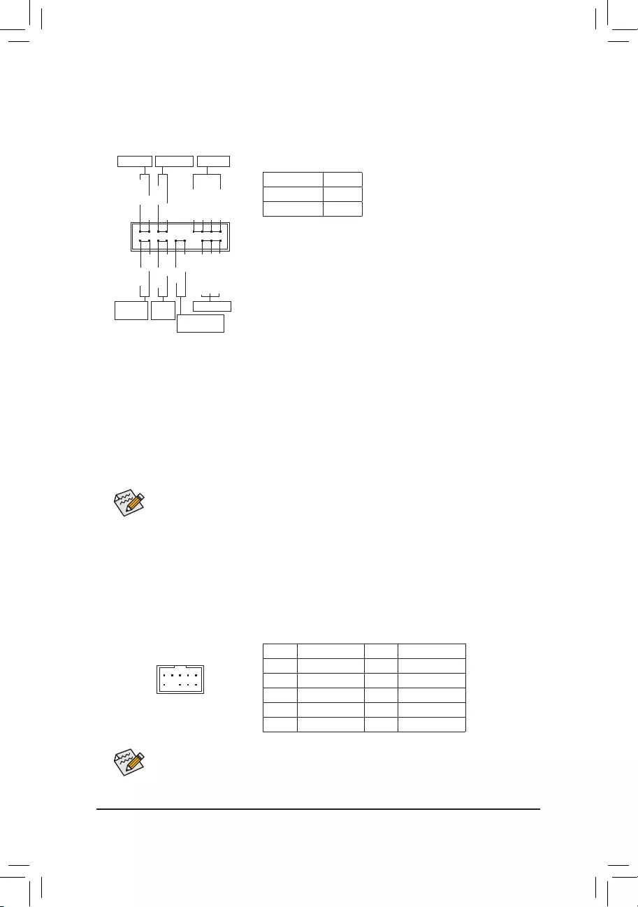
12) F_USB1/F_USB2 (USB 2.0/1.1 Headers)
TheheadersconformtoUSB2.0/1.1specication.EachUSBheadercanprovidetwoUSBportsviaan
optional USB bracket. For purchasing the optional USB bracket, please contact the local dealer.
Pin No. Denition Pin No. Denition
1 Power (5V) 6 USB DY+
2 Power (5V) 7 GND
3 USB DX- 8 GND
4 USB DY— 9 No Pin
5 USB DX+ 10 NC
10
9
2
1
— 18 —
10
12
9
11
2
2
1
1
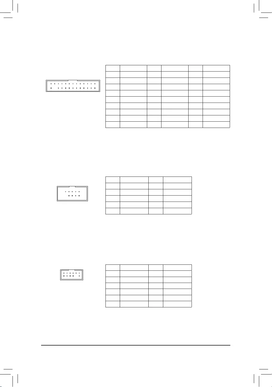
13) LPT (Parallel Port Header)
The LPT header can provide one parallel port via an optional LPT port cable. For purchasing the optional
LPT port cable, please contact the local dealer.
Pin No. Denition Pin No. Denition Pin No. Denition
1STB- 10 GND 19 ACK-
2AFD- 11 PD4 20 GND
3PD0 12 GND 21 BUSY
4ERR- 13 PD5 22 GND
5PD1 14 GND 23 PE
6INIT— 15 PD6 24 No Pin
7PD2 16 GND 25 SLCT
8SLIN- 17 PD7 26 GND
9PD3 18 GND
1
226
25
14) COM (Serial Port Header)
The COM header can provide one serial port via an optional COM port cable. For purchasing the optional
COM port cable, please contact the local dealer.
Pin No. Denition Pin No. Denition
1 NDCD- 6 NDSR-
2 NSIN 7 NRTS-
3 NSOUT 8 NCTS-
4NDTR- 9NRI-
5 GND 10 No Pin
15) TPM (Trusted Platform Module Header)
You may connect a TPM (Trusted Platform Module) to this header.
Pin No. Denition Pin No. Denition
1LAD0 7LAD3
2VCC3 8GND
3LAD1 9LFRAME
4No Pin 10 NC
5LAD2 11 SERIRQ
6LCLK 12 LRESET
F_USB30 F_U
B_
F_ F_
_
B
BS_
B
SB_
B
_S
S_
_
B
_U
_
B
S
123
123
123
123
1
1
1
1
BSS
S
_S
SSU
1 2 3 4 5
S3 BSSS
U
__ 3
F_USB3F
S _
S _
S _
SF
B_
B_
F
_0
S
S
_0F
_F
_
_
__B
U
S _S
_ SF_
B
USB0_B
B_ F_USB3
F_USB303
_
_3U
S_
— 19 —
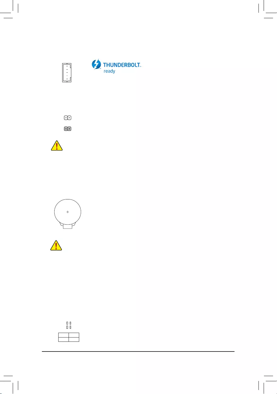
17) CLR_CMOS (Clear CMOS Jumper)
UsethisjumpertocleartheBIOScongurationandresettheCMOSvaluestofactorydefaults.Toclear
the CMOS values, use a metal object like a screwdriver to touch the two pins for a few seconds.
•Always turn off your computer and unplug the power cord from the power outlet before clearing
the CMOS values.
•Aftersystemrestart,gotoBIOSSetuptoloadfactorydefaults(selectLoadOptimizedDefaults)or
manuallyconguretheBIOSsettings(refertoChapter2,«BIOSSetup,»forBIOScongurations).
Open: Normal
Short: Clear CMOS Values
18) BAT (Battery)
Thebatteryprovidespowertokeepthevalues(suchasBIOScongurations,date,andtimeinformation)
intheCMOSwhenthecomputeristurnedoff.Replacethebatterywhenthebatteryvoltagedropstoalow
level, or the CMOS values may not be accurate or may be lost.
You may clear the CMOS values by removing the battery:
1. Turn off your computer and unplug the power cord.
2. Gently remove the battery from the battery holder and wait for one minute. (Or use a metal
object like a screwdriver to touch the positive and negative terminals of the battery holder,
making them short for 5 seconds.)
3. Replacethebattery.
4. Plug in the power cord and restart your computer.
•Always turn off your computer and unplug the power cord before replacing the battery.
•Replacethebatterywithanequivalentone.Damagetoyourdevicesmayoccurifthebatteryis
replaced with an incorrect model.
•Contact the place of purchase or local dealer if you are not able to replace the battery by yourself
or uncertain about the battery model.
•When installing the battery, note the orientation of the positive side (+) and the negative side (-)
of the battery (the positive side should face up).
•Used batteries must be handled in accordance with local environmental regulations.
16) THB_C (Thunderbolt™ Add-in Card Connector)
This connector is for a GIGABYTE Thunderbolt™ add-in card.
Supports a Thunderbolt™ add-in card.
F_USB30 F_U
B_
F_ F_
_
B
BS_
B
SB_
B
_S
S_
_
B
_U
_
B
S
123
123
123
123
1
1
1
1
BSS
S
_S
SSU
1 2 3 4 5
S3 BSSS
U
__ 3
F_USB3F
S _
S _
S _
SF
B_
B_
F
_0
S
S
_0F
_F
_
_
__B
U
S _S
_ SF_
B
USB0_B
B_ F_USB3
F_USB303
_
_3U
S_
1
19) CPU/DRAM/VGA/BOOT (Status LEDs)
The status LEDs show whether the CPU, memory, graphics card, and operating system are working
properlyaftersystempower-on.IftheCPU/DRAM/VGALEDison,thatmeansthecorrespondingdevice
is not working normally; if the BOOT LED is on, that means you haven’t entered the operating system yet.
CPU:CPU status LED
DRAM:Memory status LED
VGA:Graphics card status LED
BOOT:Operating system status LED
F_USB30 F_U
B_
F_ F_
_
B
BS_
B
SB_
B
_S
S_
_
B
_U
_
B
S
123
123
123
123
1
1
1
1
BSS
S
_S
SSU
1 2 3 4 5
S3 BSSS
U
__ 3
F_USB3F
S _
S _
S _
SF
B_
B_
F
_0
S
S
_0F
_F
_
_
__B
U
S _S
_ SF_
B
USB0_B
B_ F_USB3
F_USB303
_
_3U
S_
CPU DRAM
VGA BOOT
— 20 —
BIOS (Basic Input and Output System) records hardware parameters of the system in the CMOS on the
motherboard. Its major functions include conducting the Power-On Self-Test (POST) during system startup,
saving system parameters and loading operating system, etc. BIOS includes a BIOS Setup program that allows
theusertomodifybasicsystemcongurationsettingsortoactivatecertainsystemfeatures.
When the power is turned off, the battery on the motherboard supplies the necessary power to the CMOS to
keepthecongurationvaluesintheCMOS.
To access the BIOS Setup program, press the <Delete> key during the POST when the power is turned on.
To upgrade the BIOS, use either the GIGABYTE Q-Flash or @BIOS utility.
•Q-Flash allows the user to quickly and easily upgrade or back up BIOS without entering the operating system.
•@BIOS is a Windows-based utility that searches and downloads the latest version of BIOS from the Internet
and updates the BIOS.
Chapter 2 BIOS Setup
•BecauseBIOSashingispotentiallyrisky,ifyoudonotencounterproblemsusingthecurrentversionofBIOS,
itisrecommendedthatyounotashtheBIOS.ToashtheBIOS,doitwithcaution.InadequateBIOSashing
may result in system malfunction.
•It is recommended that you not alter the default settings (unless you need to) to prevent system instability or other
unexpected results. Inadequately altering the settings may result in system’s failure to boot. If this occurs, try to
cleartheCMOSvaluesandresettheboardtodefaultvalues.(Refertothe»LoadOptimizedDefaults»sectionin
this chapter or introductions of the battery/clear CMOS jumper in Chapter 1 for how to clear the CMOS values.)
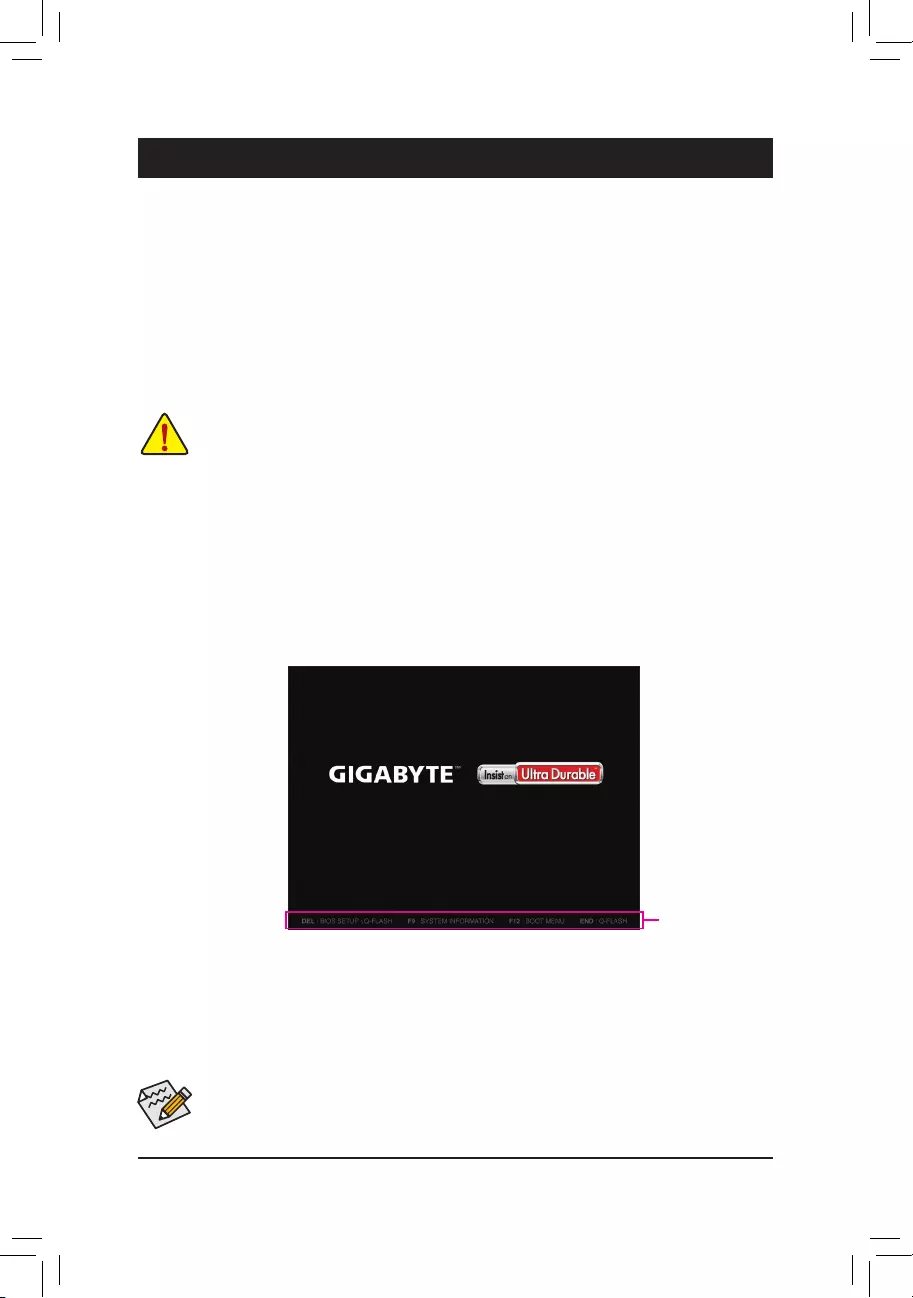
2-1 Startup Screen
The following startup Logo screen will appear when the computer boots.
(Sample BIOS Version: T13)
•When the system is not stable as usual, select the Load Optimized Defaults item to set your system to its defaults.
•The BIOS Setup menus described in this chapter are for reference only and may differ by BIOS version.
There are two different BIOS modes as follows and you can use the <F2> key to switch between the two modes.
The Classic Setup mode provides detailed BIOS settings. You can press the arrow keys on your keyboard to move
among the items and press <Enter> to accept or enter a sub-menu. Or you can use your mouse to select the
item you want. Easy Mode allows users to quickly view their current system information or to make adjustments
foroptimumperformance.InEasyMode,youcanuseyourmousetomovethroughcongurationitems.
Function Keys
— 21 —
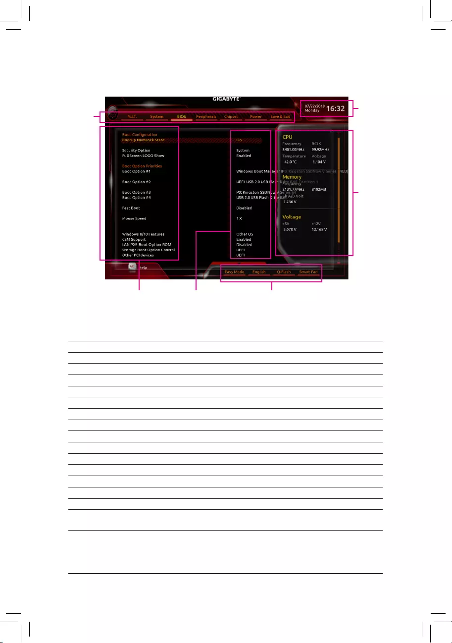
2-2 The Main Menu
Classic Setup Function Keys
<f><g> Move the selection bar to select a setup menu
<h><i>Movetheselectionbartoselectancongurationitemonamenu
<Enter>/Double Click Execute command or enter a menu
<+>/<Page Up> Increase the numeric value or make changes
<—>/<Page Down> Decrease the numeric value or make changes
<F1> Show descriptions of the function keys
<F2> Switch to Easy Mode
<F3> SavethecurrentBIOSsettingstoaprole
<F4> LoadtheBIOSsettingsfromaprolecreatedbefore
<F5> RestorethepreviousBIOSsettingsforthecurrentsubmenus
<F7> LoadtheOptimizedBIOSdefaultsettingsforthecurrentsubmenus
<F8> Access the Q-Flash utility
<F9> Display system information
<F10> Save all the changes and exit the BIOS Setup program
<F12> Capture the current screen as an image and save it to your USB drive
<Esc> Main Menu: Exit the BIOS Setup program
Submenus: Exit current submenu
Hardware
Information
CongurationItems Current Settings
Setup
Menus
System Time
Quick Access Bar allows you to enter Easy Mode, select
BIOSdefaultlanguage,congurefansettings,orenter
Q-Flash.
— 22 —
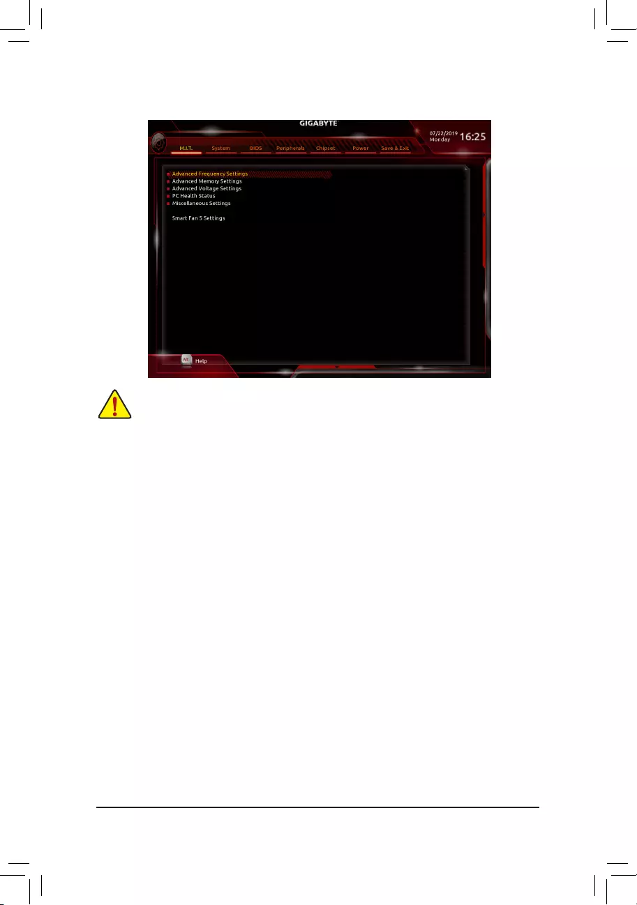
2-3 M.I.T.
Whether the system will work stably with the overclock/overvoltage settings you made is dependent on your overall
systemcongurations.Incorrectlydoingoverclock/overvoltagemayresultindamagetoCPU,chipset,ormemory
and reduce the useful life of these components. This page is for advanced users only and we recommend you not to
alter the default settings to prevent system instability or other unexpected results. (Inadequately altering the settings
may result in system’s failure to boot. If this occurs, clear the CMOS values and reset the board to default values.)
`Advanced Frequency Settings
&Host Clock Value
Displays the current operating Host Clock frequency.
&Graphics Slice Ratio (Note)
AllowsyoutosettheGraphicsSliceRatio.
&Graphics UnSlice Ratio (Note)
AllowsyoutosettheGraphicsUnSliceRatio.
&CPU Clock Ratio
Allows you to alter the clock ratio for the installed CPU. The adjustable range is dependent on the CPU
being installed.
&CPU Frequency
Displays the current operating CPU frequency.
&FCLK Frequency for Early Power On
AllowsyoutosettheFCLKfrequency.Optionsare:Normal(800Mhz),1GHz,400MHz.(Default:1GHz)
`Advanced CPU Core Settings
&CPU Clock Ratio, CPU Frequency, FCLK Frequency for Early Power On
The settings above are synchronous to those under the same items on the Advanced Frequency Settings
menu.
(Note) This item is present only when you install a CPU that supports this feature. For more information about
Intel® CPUs’ unique features, please visit Intel’s website.
— 23 —

&Uncore Ratio
Allows you to set the CPU Uncore ratio. The adjustable range is dependent on the CPU being used.
&Uncore Frequency
Displays the current CPU Uncore frequency.
&CPU Flex Ratio Override
EnablesordisablestheCPUFlexRatio.ThemaximumCPUclockratiowillbebasedontheCPU Flex
Ratio Settings value if CPU Clock Ratio is set to Auto. (Default: Disabled)
&CPU Flex Ratio Settings
AllowsyoutosettheCPUFlexRatio.TheadjustablerangemayvarybyCPU.
&Intel(R) Turbo Boost Technology (Note)
Allows you to determine whether to enable the Intel® CPU Turbo Boost technology. Auto lets the BIOS
automaticallycongurethissetting.(Default:Auto)
&Turbo Ratio (Note)
Allows you to set the CPU Turbo ratios for different number of active cores. Auto sets the CPU Turbo ratios
accordingtotheCPUspecications.(Default:Auto)
&No. of CPU Cores Enabled (Note)
Allows you to select the number of CPU cores to enable in an Intel® multi-core CPU (the number of CPU
cores may vary by CPU). AutoletstheBIOSautomaticallycongurethissetting.(Default:Auto)
&Hyper-Threading Technology (Note)
Allows you to determine whether to enable multi-threading technology when using an Intel® CPU that
supports this function. This feature only works for operating systems that support multi-processor mode.
AutoletstheBIOSautomaticallycongurethissetting.(Default:Auto)
&Intel(R) Speed Shift Technology (Intel® Speed Shift Technology) (Note)
Enables or disables Intel® Speed Shift Technology. Enabling this feature allows the processor to ramp up
its operating frequency more quickly and then improves the system responsiveness. (Default: Auto)
&CPU Enhanced Halt (C1E) (Note)
Enables or disables Intel
®
CPU Enhanced Halt (C1E) function, a CPU power-saving function in system halt
state.
When enabled, the CPU core frequency and voltage will be reduced during system halt state to
decrease power consumption. AutoletstheBIOSautomaticallycongurethissetting.(Default:Auto)
&C3 State Support (Note)
Allows you to determine whether to let the CPU enter C3 mode in system halt state. When enabled, the
CPU core frequency and voltage will be reduced during system halt state to decrease power consumption.
The C3 state is a more enhanced power-saving state than C1. AutoletstheBIOSautomaticallycongure
this setting. (Default: Auto)
&C6/C7 State Support (Note)
Allows you to determine whether to let the CPU enter C6/C7 mode in system halt state. When enabled, the
CPU core frequency and voltage will be reduced during system halt state to decrease power consumption.
The C6/C7 state is a more enhanced power-saving state than C3. AutoletstheBIOSautomaticallycongure
this setting. (Default: Auto)
&C8 State Support (Note)
Allows you to determine whether to let the CPU enter C8 mode in system halt state. When enabled, the CPU
core frequency and voltage will be reduced during system halt state to decrease power consumption. The
C8 state is a more enhanced power-saving state than C6/C7. AutoletstheBIOSautomaticallycongure
this setting. (Default: Auto)
(Note) This item is present only when you install a CPU that supports this feature. For more information about
Intel® CPUs’ unique features, please visit Intel’s website.
— 24 —

&C10 State Support (Note 1)
Allows you to determine whether to let the CPU enter C10 mode in system halt state. When enabled, the
CPU core frequency and voltage will be reduced during system halt state to decrease power consumption.
The C10 state is a more enhanced power-saving state than C8. AutoletstheBIOSautomaticallycongure
this setting. (Default: Auto)
&Package C State Limit (Note 1)
Allows you to specify the C-state limit for the processor. AutoletstheBIOSautomaticallycongurethis
setting. (Default: Auto)
&CPU Thermal Monitor (Note 1)
Enables or disables Intel® Thermal Monitor function, a CPU overheating protection function. When enabled,
the CPU core frequency and voltage will be reduced when the CPU is overheated. Auto lets the BIOS
automaticallycongurethissetting.(Default:Auto)
&Ring to Core offset (Down Bin)
AllowsyoutodeterminewhethertodisabletheCPURingratioauto-downfunction.Auto lets the BIOS
automaticallycongurethissetting.(Default:Auto)
&CPU EIST Function (Note 1)
Enables or disables Enhanced Intel® Speed Step Technology (EIST). Depending on CPU loading, Intel®
EIST technology can dynamically and effectively lower the CPU voltage and core frequency to decrease
average power consumption and heat production. AutoletstheBIOSautomaticallycongurethissetting.
(Default: Auto)
&Race To Halt (RTH) (Note 1)/EnergyEfcientTurbo (Note 1)
Enables or disables the CPU power saving related settings.
&Voltage Optimization
Allowsyoutodeterminewhethertoenablevoltageoptimizationtoreducepowerconsumption.(Default:
Auto)
&Hardware Prefetcher
Allows you to determine whether to enable hardware prefetcher to prefetch data and instructions from the
memory into the cache. (Default: Auto)
&Adjacent Cache Line Prefetch
Allows you to determine whether to enable the adjacent cache line prefetch mechanism that lets the
processor retrieve the requested cache line as well as the subsequent cache line. (Default: Auto)
&ExtremeMemoryProle(X.M.P.)(Note 2)
Allows the BIOS to read the SPD data on XMP memory module(s) to enhance memory performance when
enabled.
Disabled Disables this function. (Default)
Prole1 UsesProle1settings.
Prole2(Note 2) UsesProle2settings.
&System Memory Multiplier
Allows you to set the system memory multiplier. Auto sets memory multiplier according to memory SPD
data. (Default: Auto)
&Memory Ref Clock
Allows you to manually adjust the memory reference clock. (Default: Auto)
&Memory Odd Ratio (100/133 or 200/266)
Enabled allows Qclk to run in odd frequency. (Default: Auto)
(Note 1) This item is present only when you install a CPU that supports this feature. For more information about
Intel® CPUs’ unique features, please visit Intel’s website.
(Note 2) This item is present only when you install a CPU and a memory module that support this feature.
— 25 —

&Memory Frequency (MHz)
Therstmemoryfrequencyvalueisthenormaloperatingfrequencyofthememorybeingused;thesecond
is the memory frequency that is automatically adjusted according to the System Memory Multiplier settings.
`Advanced Memory Settings
&ExtremeMemoryProle(X.M.P.)(Note), System Memory Multiplier, Memory Ref Clock,
Memory Odd Ratio (100/133 or 200/266), Memory Frequency(MHz)
The settings above are synchronous to those under the same items on the Advanced Frequency Settings
menu.
&Memory Boot Mode (Note)
Provides memory detection and training methods.
Auto LetstheBIOSautomaticallycongurethissetting.(Default)
Normal The BIOS automatically performs memory training. Please note that if the system
becomes unstable or unbootable, try to clear the CMOS values and reset the board
todefaultvalues.(Refertotheintroductionsofthebattery/clearCMOSjumperin
Chapter 1 for how to clear the CMOS values.)
EnableFastBoot Skipmemorydetectionandtraininginsomespeciccriteriaforfastermemory
boot.
Disable Fast Boot Detect and train memory at every single boot.
&Realtime Memory Timing
Allowsyoutone-tunememorytimingsaftertheBIOSstage.(Default:Auto)
&Memory Enhancement Settings
Providesseveralmemoryperformanceenhancementsettings:Normal(basicperformance),RelaxOC,
Enhanced Stability, and Enhanced Performance. (Default: Normal)
&Memory Timing Mode
Manual and Advanced Manual allows the Memory Multiplier Tweaker, Channel Interleaving, Rank
Interleaving,andmemorytimingsettingsbelowtobecongurable.Optionsare:Auto(default),Manual,
Advanced Manual.
&ProleDDRVoltage
When using a non-XMP memory module or ExtremeMemoryProle(X.M.P.) is set to Disabled, the value
isdisplayedaccordingtoyourmemoryspecication.WhenExtremeMemoryProle(X.M.P.) is set to
Prole1 or Prole2, the value is displayed according to the SPD data on the XMP memory.
&Memory Multiplier Tweaker
Provides different levels of memory auto-tuning. (Default: Auto)
&Channel Interleaving
Enables or disables memory channel interleaving. Enabled allows the system to simultaneously access
different channels of the memory to increase memory performance and stability. Auto lets the BIOS
automaticallycongurethissetting.(Default:Auto)
&Rank Interleaving
Enables or disables memory rank interleaving. Enabled allows the system to simultaneously access different
ranks of the memory to increase memory performance and stability. Auto lets the BIOS automatically
congurethissetting.(Default:Auto)
(Note) This item is present only when you install a CPU and a memory module that support this feature.
— 26 —

`Channel A/B Memory Sub Timings
This sub-menu provides memory timing settings for each channel of memory. The respective timing setting
screensarecongurableonlywhenMemory Timing Mode is set to Manual or Advanced Manual. Note:
Your system may become unstable or fail to boot after you make changes on the memory timings. If this
occurs,pleaseresettheboardtodefaultvaluesbyloadingoptimizeddefaultsorclearingtheCMOSvalues.
`Advanced Voltage Settings
`Advanced Power Settings
&CPU Vcore Loadline Calibration
AllowsyoutocongureLoad-LineCalibrationfortheCPUVcorevoltage.Selectingahigherlevelkeeps
the CPU Vcore voltage more consistent with what is set in BIOS under heavy load. Auto lets the BIOS
automaticallycongurethissettingandsetsthevoltagefollowingIntel’sspecications.(Default:Auto)
`CPU Core Voltage Control
This section provides CPU voltage control options.
`Chipset Voltage Control
This section provides Chipset voltage control options.
`DRAM Voltage Control
This section provides memory voltage control options.
`Internal VR Control
ThissectionprovidesVRvoltagecontroloptions.
`PC Health Status
&Reset Case Open Status
Disabled Keeps or clears the record of previous chassis intrusion status. (Default)
Enabled Clears the record of previous chassis intrusion status and the Case Openeldwill
show»No»atnextboot.
&Case Open
Displays the detection status of the chassis intrusion detection device attached to the motherboard CI
header.Ifthesystemchassiscoverisremoved,thiseldwillshow«Yes»,otherwiseitwillshow«No».To
clear the chassis intrusion status record, set Reset Case Open Status to Enabled, save the settings to
the CMOS, and then restart your system.
& CPU Vcore/CPU VCCSA/DRAM Channel A/B Voltage/+3.3V/+5V/+12V/CPU VAXG
Displays the current system voltages.
`Miscellaneous Settings
&Max Link Speed
Allows you to set the operation mode of the PCI Express slots to Gen 1, Gen 2, or Gen 3. Actual operation
modeissubjecttothehardwarespecicationofeachslot.AutoletstheBIOSautomaticallycongurethis
setting. (Default: Auto)
&3DMark01 Enhancement
Allows you to determine whether to enhance some legacy benchmark performance. (Default: Disabled)
`Smart Fan 5 Settings
&Monitor
Allows you to select a target to monitor and to make further adjustment. (Default: CPU FAN)
— 27 —

&Fan Speed Control
Allows you to determine whether to enable the fan speed control function and adjust the fan speed.
Normal Allows the fan to run at different speeds according to the temperature. You can adjust
the fan speed with System Information Viewer based on your system requirements.
(Default)
Silent Allows the fan to run at slow speeds.
Manual Allows you to control the fan speed in the curve graph.
Full Speed Allows the fan to run at full speeds.
&Fan Control Use Temperature Input
Allows you to select the reference temperature for fan speed control.
&Temperature Interval
Allows you to select the temperature interval for fan speed change.
&Fan Control mode
Auto Lets the BIOS automatically detect the type of fan installed and sets the optimal control
mode. (Default)
Voltage Voltage mode is recommended for a 3-pin fan.
PWM PWM mode is recommended for a 4-pin fan.
&Fan Stop
Enables or disables the fan stop function. You can set the temperature limit using the temperature curve.
The fan stops operation when the temperature is lower than the limit. (Default: Disabled)
&Temperature
Displays the current temperature of the selected target area.
&Fan Speed
Displays current fan speeds.
&Temperature Warning Control
Sets the warning threshold for temperature. When temperature exceeds the threshold, BIOS will emit
warning sound. Options are: Disabled (default), 60oC/140oF, 70oC/158oF, 80oC/176oF, 90oC/194oF.
&Fan Fail Warning
Allows the system to emit warning sound if the fan is not connected or fails. Check the fan condition or fan
connection when this occurs. (Default: Disabled)
— 28 —
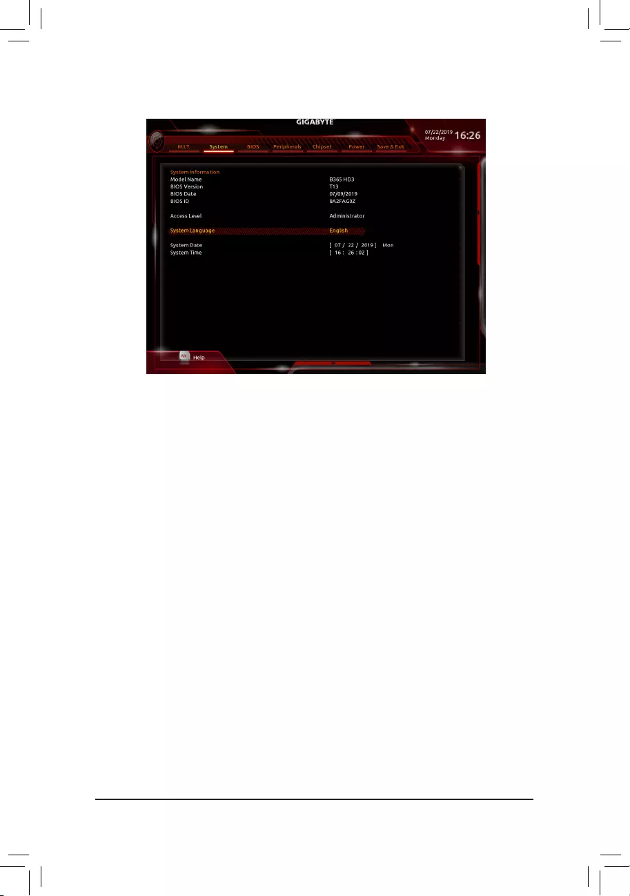
2-4 System
This section provides information on your motherboard model and BIOS version. You can also select the default
language used by the BIOS and manually set the system time.
&Access Level
Displays the current access level depending on the type of password protection used. (If no password is
set, the default will display as Administrator.) The Administrator level allows you to make changes to all
BIOS settings; the User level only allows you to make changes to certain BIOS settings but not all.
&System Language
Selects the default language used by the BIOS.
&System Date
Sets the system date. The date format is week (read-only), month, date, and year. Use <Enter> to switch
betweentheMonth,Date,andYeareldsandusethe<PageUp>or<PageDown>keytosetthedesired
value.
&System Time
Sets the system time. The time format is hour, minute, and second. For example, 1 p.m. is 13:00:00. Use
<Enter>toswitchbetweentheHour,Minute,andSecondeldsandusethe<PageUp>or<PageDown>
key to set the desired value.
— 29 —
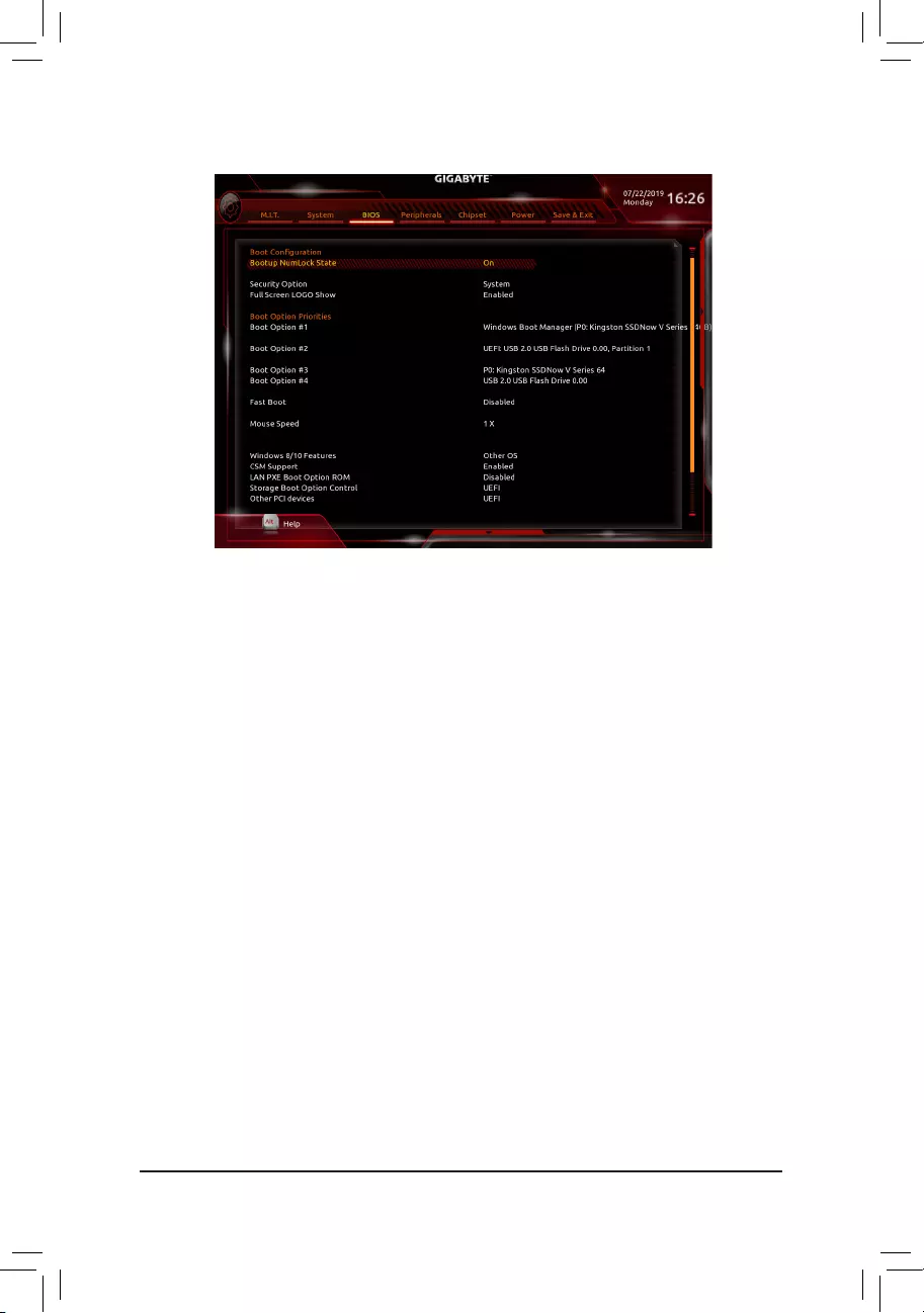
2-5 BIOS
&Bootup NumLock State
Enables or disables Numlock feature on the numeric keypad of the keyboard after the POST. (Default: On)
&Security Option
Specieswhetherapasswordisrequiredeverytimethesystemboots,oronlywhenyouenterBIOSSetup.
Afterconguringthisitem,setthepassword(s)undertheAdministrator Password/User Password item.
Setup A password is only required for entering the BIOS Setup program.
System A password is required for booting the system and for entering the BIOS Setup program.
(Default)
&Full Screen LOGO Show
Allows you to determine whether to display the GIGABYTE Logo at system startup. Disabled skips the
GIGABYTE Logo when the system starts up. (Default: Enabled)
&Boot Option Priorities
Speciestheoverallbootorderfromtheavailabledevices.RemovablestoragedevicesthatsupportGPT
formatwillbeprexedwith«UEFI:»stringonthebootdevicelist.Tobootfromanoperatingsystemthat
supportsGPTpartitioning,selectthedeviceprexedwith»UEFI:»string.
Or if you want to install an operating system that supports GPT partitioning such as Windows 10 64-bit,
selecttheopticaldrivethatcontainstheWindows1064-bitinstallationdiscandisprexedwith«UEFI:»
string.
& Hard Drive/CD/DVD ROM Drive/Floppy Drive/Network Device BBS Priorities
Speciesthebootorderforaspecicdevicetype,suchasharddrives,opticaldrives,oppydiskdrives,
and devices that support Boot from LAN function, etc. Press <Enter> on this item to enter the submenu that
presents the devices of the same type that are connected. This item is present only if at least one device
for this type is installed.
&Fast Boot
Enables or disables Fast Boot to shorten the OS boot process. Ultra Fast provides the fastest bootup
speed. (Default: Disabled)
— 30 —

&SATA Support
Last Boot HDD Only Except for the previous boot drive, all SATA devices are disabled before the OS
boot process completes.
All Sata Devices All SATA devices are functional in the operating system and during the POST.
(Default)
ThisitemiscongurableonlywhenFast Boot is set to Enabled or Ultra Fast.
&VGA Support
Allows you to select which type of operating system to boot.
Auto EnableslegacyoptionROMonly.
EFIDriver EnablesEFIoptionROM.(Default)
ThisitemiscongurableonlywhenFast Boot is set to Enabled or Ultra Fast.
&USB Support
Disabled All USB devices are disabled before the OS boot process completes.
Full Initial All USB devices are functional in the operating system and during the POST.
Partial Initial Part of the USB devices are disabled before the OS boot process completes.
(Default)
ThisitemiscongurableonlywhenFast Boot is set to Enabled. This function is disabled when Fast Boot
is set to Ultra Fast.
&PS2 Devices Support
Disabled All PS/2 devices are disabled before the OS boot process completes.
Enabled All PS/2 devices are functional in the operating system and during the POST.
(Default)
ThisitemiscongurableonlywhenFast Boot is set to Enabled. This function is disabled when Fast Boot
is set to Ultra Fast.
&NetWork Stack Driver Support
Disabled Disables booting from the network. (Default)
Enabled Enables booting from the network.
ThisitemiscongurableonlywhenFast Boot is set to Enabled or Ultra Fast.
&Next Boot After AC Power Loss
Normal Boot Enables normal bootup upon the return of the AC power. (Default)
Fast Boot Keeps the Fast Boot settings upon the return of the AC power.
ThisitemiscongurableonlywhenFast Boot is set to Enabled or Ultra Fast.
&Mouse Speed
Allows you to set the mouse cursor movement speed. (Default: 1 X)
&Windows 8/10 Features
Allows you to select the operating system to be installed. (Default: Other OS)
&CSM Support
Enables or disables UEFI CSM (Compatibility Support Module) to support a legacy PC boot process.
Disabled Disables UEFI CSM and supports UEFI BIOS boot process only.
Enabled Enables UEFI CSM. (Default)
&LAN PXE Boot Option ROM
AllowsyoutoselectwhethertoenablethelegacyoptionROMfortheLANcontroller.(Default:Disabled)
ThisitemiscongurableonlywhenCSM Support is set to Enabled.
— 31 —

&Storage Boot Option Control
AllowsyoutoselectwhethertoenabletheUEFIorlegacyoptionROMforthestoragedevicecontroller.
Donotlaunch DisablesoptionROM.
UEFI EnablesUEFIoptionROMonly.(Default)
Legacy EnableslegacyoptionROMonly.
ThisitemiscongurableonlywhenCSM Support is set to Enabled.
&Other PCI devices
AllowsyoutoselectwhethertoenabletheUEFIorLegacyoptionROMforthePCIdevicecontrollerother
than the LAN, storage device, and graphics controllers.
Donotlaunch DisablesoptionROM.
UEFI EnablesUEFIoptionROMonly.(Default)
Legacy EnableslegacyoptionROMonly.
ThisitemiscongurableonlywhenCSM Support is set to Enabled.
&Administrator Password
Allowsyoutocongureanadministratorpassword.Press<Enter>onthisitem,typethepassword,and
thenpress<Enter>.Youwillberequestedtoconrmthepassword.Typethepasswordagainandpress
<Enter>. You must enter the administrator password (or user password) at system startup and when entering
BIOS Setup. Differing from the user password, the administrator password allows you to make changes to
all BIOS settings.
&User Password
Allowsyoutocongureauserpassword.Press<Enter>onthisitem,typethepassword,andthenpress
<Enter>.Youwillberequestedtoconrmthepassword.Typethepasswordagainandpress<Enter>.
You must enter the administrator password (or user password) at system startup and when entering BIOS
Setup. However, the user password only allows you to make changes to certain BIOS settings but not all.
To cancel the password, press <Enter> on the password item and when requested for the password, enter
thecorrectonerst.Whenpromptedforanewpassword,press<Enter>withoutenteringanypassword.
Press<Enter>againwhenpromptedtoconrm.
NOTE:BeforesettingtheUserPassword,besuretosettheAdministratorPasswordrst.
&Secure Boot
AllowsyoutoenableordisableSecureBootandcongurerelatedsettings.Thisitemiscongurableonly
when CSM Support is set to Disabled.
— 32 —
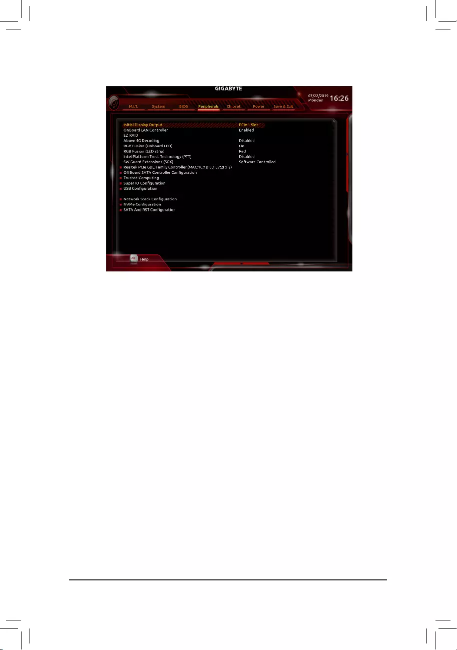
2-6 Peripherals
&Initial Display Output
SpeciestherstinitiationofthemonitordisplayfromtheinstalledPCIExpressgraphicscardortheonboard
graphics.
IGFX Setstheonboardgraphicsastherstdisplay.
PCIe1Slot SetsthegraphicscardonthePCIEX16slotastherstdisplay.(Default)
PCIe2Slot SetsthegraphicscardonthePCIEX4slotastherstdisplay.
&OnBoard LAN Controller
Enables or disables the onboard LAN function. (Default: Enabled)
If you wish to install a 3rd party add-in network card instead of using the onboard LAN, set this item to
Disabled.
&EZ RAID
AllowsyoutoquicklysetupaRAIDarray.RefertoChapter3,«ConguringaRAIDSet,»forinstructions
onconguringaRAIDarray.
&Above 4G Decoding
Enables or disables 64-bit capable devices to be decoded in above 4 GB address space (only if your system
supports 64-bit PCI decoding). Set to Enabled if more than one advanced graphics card are installed and
their drivers are not able to be launched when entering the operating system (because of the limited 4 GB
memory address space). (Default: Disabled)
&RGB Fusion (Onboard LED)
Allows you to set the LED lighting mode for the motherboard.
On Enables this function. (Default)
Off Disables this function.
Pulse Mode All LEDs simultaneously fade in and fade out.
&RGB Fusion (LED strip)
Allows you to set the display color of the external LED strip.
&Intel Platform Trust Technology (PTT)
Enables or disables Intel® PTT Technology. (Default: Disabled)
— 33 —

&SW Guard Extensions (SGX)
Enables or disables the Intel® Software Guard Extensions technology. This feature allows legal software
to operate in a safe environment and protects the software against attacks from malicious software. The
Software Controlled option allows you to enable or disable this feature with an Intel-provided application.
(Default: Software Controlled)
`Realtek PCIe GBE Family Controller
Thissub-menuprovidesinformationonLANcongurationandrelatedcongurationoptions.
`OffBoardSATAControllerConguration
Displays information on your M.2 PCIe SSD if installed.
`Trusted Computing
Enables or disables Trusted Platform Module (TPM).
`SuperIOConguration
&Serial Port
Enables or disables the onboard serial port. (Default: Enabled)
&Parallel Port
Enables or disables the onboard parallel port. (Default: Enabled)
`USBConguration
&Legacy USB Support
Allows USB keyboard/mouse to be used in MS-DOS. (Default: Enabled)
&XHCI Hand-off
Determines whether to enable XHCI Hand-off feature for an operating system without XHCI Hand-off
support. (Default: Disabled)
&USB Mass Storage Driver Support
Enables or disables support for USB storage devices. (Default: Enabled)
&Port 60/64 Emulation
Enables or disables emulation of I/O ports 64h and 60h. This should be enabled for full legacy support
for USB keyboards/mice in MS-DOS or in operating system that does not natively support USB devices.
(Default: Enabled)
&Mass Storage Devices
Displays a list of connected USB mass storage devices. This item appears only when a USB storage device
is installed.
`NetworkStackConguration
&Network Stack
Disables or enables booting from the network to install a GPT format OS, such as installing the OS from
the Windows Deployment Services server. (Default: Disabled)
&Ipv4 PXE Support
EnablesordisablesIPv4PXESupport.ThisitemiscongurableonlywhenNetwork Stack is enabled.
&Ipv4 HTTP Support
EnablesordisablesHTTPbootsupportforIPv4.ThisitemiscongurableonlywhenNetwork Stack is
enabled.
— 34 —

&Ipv6 PXE Support
EnablesordisablesIPv6PXESupport.ThisitemiscongurableonlywhenNetwork Stack is enabled.
&Ipv6 HTTP Support
EnablesordisablesHTTPbootsupportforIPv6.ThisitemiscongurableonlywhenNetwork Stack is
enabled.
&PXE boot wait time
Allowsyoutocongurehowlongtowaitbeforeyoucanpress<Esc>toabortthePXEboot.Thisitemis
congurableonlywhenNetwork Stack is enabled. (Default: 0)
&Media detect count
Allowsyoutosetthenumberoftimestocheckthepresenceofmedia.Thisitemiscongurableonlywhen
Network Stack is enabled. (Default: 1)
`NVMeConguration
Displays information on your M.2 NVME PCIe SSD if installed.
`SATAAndRSTConguration
&SATA Controller(s)
Enables or disables the integrated SATA controllers. (Default: Enabled)
&SATA Mode Selection
EnablesordisablesRAIDfortheSATAcontrollersintegratedintheChipsetorcongurestheSATAcontrollers
to AHCI mode.
IntelRSTPremiumWithIntelOptaneSystemAcceleration EnablesRAIDfortheSATAcontroller.
AHCI CongurestheSATAcontrollerstoAHCImode.AdvancedHostControllerInterface
(AHCI)isaninterfacespecicationthatallowsthestoragedrivertoenableadvanced
Serial ATA features such as Native Command Queuing and hot plug. (Default)
&Aggressive LPM Support
Enables or disables the power saving feature, ALPM (Aggressive Link Power Management), for the Chipset
SATA controllers. (Default: Disabled)
&Port 0/1/2/3/4/5
Enables or disables each SATA port. (Default: Enabled)
&Hot plug
Enables or disable the hot plug capability for each SATA port. (Default: Disabled)
&ConguredaseSATA
Enables or disables support for external SATA devices.
&Mechanical Presence Switch
Allows you to determine whether to turn on the Mechanical Presence switch for the SATA device. This item
iscongurableonlywhenHot plug is enabled. (Default: Enabled)
— 35 —
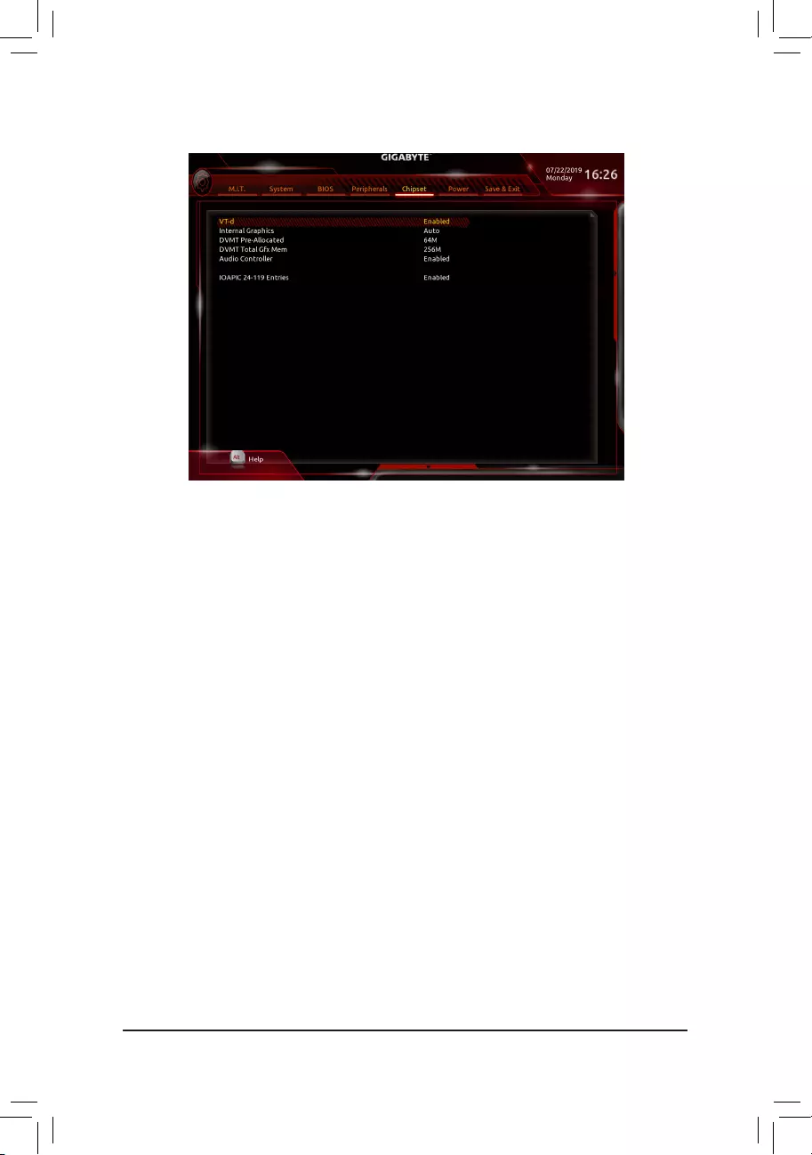
&VT-d (Note)
Enables or disables Intel®VirtualizationTechnologyforDirectedI/O.(Default:Enabled)
&Internal Graphics
Enables or disables the onboard graphics function. (Default: Auto)
&DVMT Pre-Allocated
Allowsyoutosettheonboardgraphicsmemorysize.Optionsare:32M~1024M.(Default:64M)
&DVMT Total Gfx Mem
AllowsyoutoallocatetheDVMTmemorysizeoftheonboardgraphics.Optionsare:128M,256M,MAX.
(Default: 256M)
&Audio Controller
Enables or disables the onboard audio function. (Default: Enabled)
If you wish to install a 3rd party add-in audio card instead of using the onboard audio, set this item to
Disabled.
&IOAPIC 24-119 Entries
Enables or disables this function. (Default: Enabled)
2-7 Chipset
(Note) This item is present only when you install a CPU that supports this feature. For more information about
Intel® CPUs’ unique features, please visit Intel’s website.
— 36 —
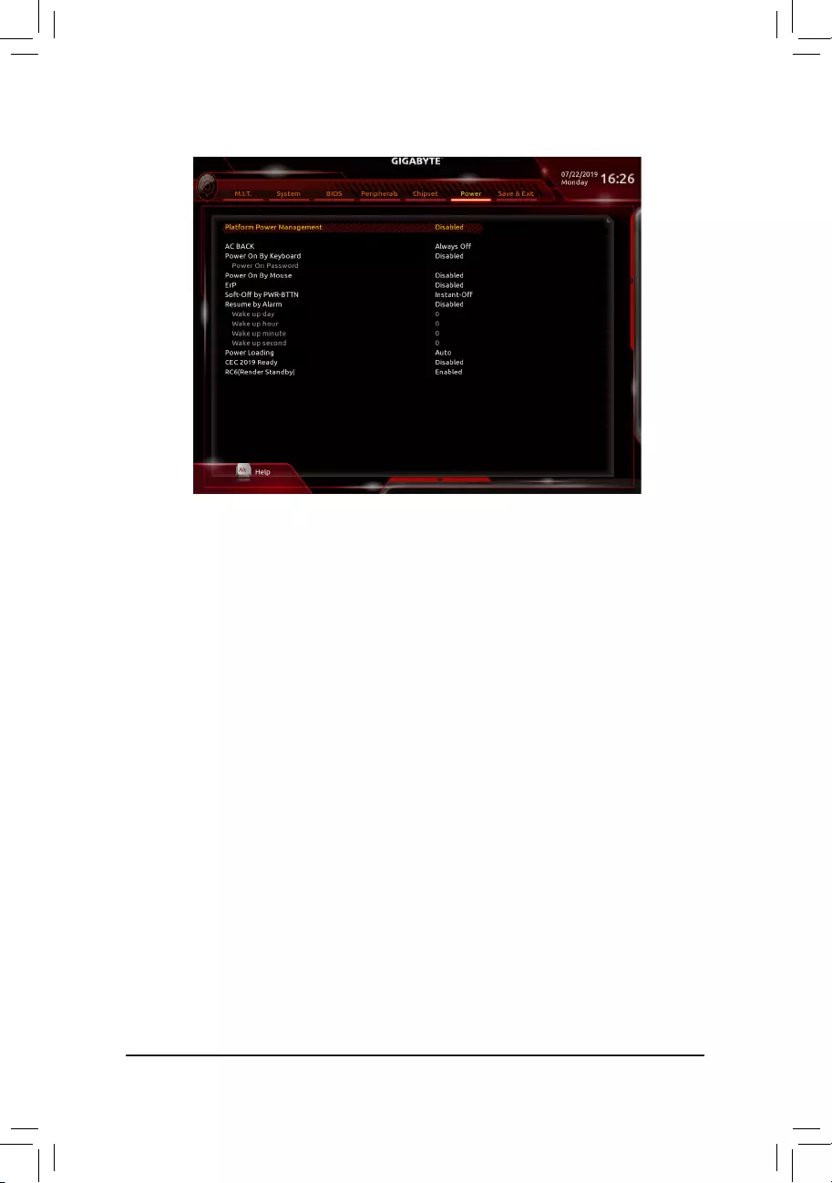
2-8 Power
&Platform Power Management
Enables or disables the Active State Power Management function (ASPM). (Default: Disabled)
&PEG ASPM
AllowsyoutoconguretheASPM mode for the device connected to the CPU PEG bus.Thisitemis
congurableonlywhenPlatform Power Management is set to Enabled. (Default: Enabled)
&PCH ASPM
AllowsyoutoconguretheASPMmodeforthedeviceconnectedtoChipset’sPCIExpressbus.Thisitem
iscongurableonlywhenPlatform Power Management is set to Enabled. (Default: Enabled)
&DMI ASPM
AllowsyoutoconguretheASPMmodeforbothCPUsideandChipsetsideoftheDMIlink.Thisitemis
congurableonlywhenPlatform Power Management is set to Enabled. (Default: Enabled)
&AC BACK
Determines the state of the system after the return of power from an AC power loss.
Memory The system returns to its last known awake state upon the return of the AC power.
Always On The system is turned on upon the return of the AC power.
Always Off The system stays off upon the return of the AC power. (Default)
&Power On By Keyboard
Allows the system to be turned on by a PS/2 keyboard wake-up event.
Note: To use this function, you need an ATX power supply providing at least 1A on the +5VSB lead.
Disabled Disables this function. (Default)
Password Setapasswordwith1~5characterstoturnonthesystem.
Keyboard98 PressPOWERbuttonontheWindows98keyboardtoturnonthesystem.
Any Key Press any key to turn on the system.
— 37 —

&Power On Password
Set the password when Power On By Keyboard is set to Password.
Press <Enter> on this item and set a password with up to 5 characters and then press <Enter> to accept.
To turn on the system, enter the password and press <Enter>.
Note: To cancel the password, press <Enter> on this item. When prompted for the password, press <Enter>
again without entering the password to clear the password settings.
&Power On By Mouse
Allows the system to be turned on by a PS/2 mouse wake-up event.
Note: To use this function, you need an ATX power supply providing at least 1A on the +5VSB lead.
Disabled Disables this function. (Default)
Move Move the mouse to turn on the system.
Double Click Double click on left button on the mouse to turn on the system.
&ErP
Determines whether to let the system consume least power in S5 (shutdown) state. (Default: Disabled)
Note: When this item is set to Enabled,thefollowingfunctionswillbecomeunavailable:ResumebyAlarm,
power on by mouse, and power on by keyboard.
&Soft-Off by PWR-BTTN
ConguresthewaytoturnoffthecomputerinMS-DOSmodeusingthepowerbutton.
Instant-Off Press the power button and then the system will be turned off instantly. (Default)
Delay 4 Sec. Press and hold the power button for 4 seconds to turn off the system. If the power
button is pressed for less than 4 seconds, the system will enter suspend mode.
&Resume by Alarm
Determines whether to power on the system at a desired time. (Default: Disabled)
If enabled, set the date and time as following:
Wakeupday:Turnonthesystemataspecictimeoneachdayoronaspecicdayinamonth.
Wake up hour/minute/second: Set the time at which the system will be powered on automatically.
Note: When using this function, avoid inadequate shutdown from the operating system or removal of the
AC power, or the settings may not be effective.
&Power Loading
Enables or disables dummy load. When the power supply is at low load, a self-protection will activate causing
it to shutdown or fail. If this occurs, please set to Enabled. AutoletstheBIOSautomaticallycongurethis
setting. (Default: Auto)
&CEC 2019 Ready
Allows you to select whether to allow the system to adjust power consumption when it is in shutdown, idle,
or standby state in order to comply with the CEC (California Energy Commission) 2019 Standards. (Default:
Disabled)
&RC6(Render Standby)
Allows you to determine whether to let the onboard graphics enter standby mode to decrease power
consumption. (Default: Enabled)
— 38 —
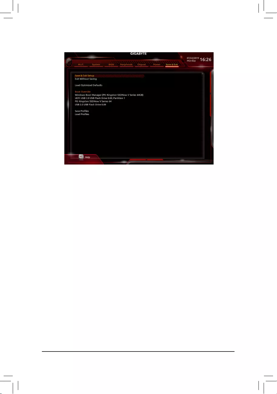
2-9 Save & Exit
&Save & Exit Setup
Press <Enter> on this item and select Yes. This saves the changes to the CMOS and exits the BIOS Setup
program. Select No or press <Esc> to return to the BIOS Setup Main Menu.
&Exit Without Saving
Press <Enter> on this item and select Yes. This exits the BIOS Setup without saving the changes made
in BIOS Setup to the CMOS. Select No or press <Esc> to return to the BIOS Setup Main Menu.
&Load Optimized Defaults
Press <Enter> on this item and select Yes to load the optimal BIOS default settings. The BIOS defaults
settingshelpthesystemtooperateinoptimumstate.AlwaysloadtheOptimizeddefaultsafterupdating
the BIOS or after clearing the CMOS values.
&Boot Override
Allows you to select a device to boot immediately. Press <Enter> on the device you select and select Yes
toconrm.Yoursystemwillrestartautomaticallyandbootfromthatdevice.
&SaveProles
ThisfunctionallowsyoutosavethecurrentBIOSsettingstoaprole.Youcancreateupto8prolesand
saveasSetupProle1~SetupProle8.Press<Enter>tocomplete.OryoucanselectSelect File in
HDD/FDD/USBtosavetheproletoyourstoragedevice.
&LoadProles
If your system becomes unstable and you have loaded the BIOS default settings, you can use this function
toloadtheBIOSsettingsfromaprole createdbefore,without thehasslesofreconguringtheBIOS
settings.Firstselecttheproleyouwishtoloadandthenpress<Enter>tocomplete.YoucanselectSelect
File in HDD/FDD/USBtoinputtheprolepreviouslycreatedfromyourstoragedeviceorloadtheprole
automatically created by the BIOS, such as reverting the BIOS settings to the last settings that worked
properly (last known good record).
— 39 —
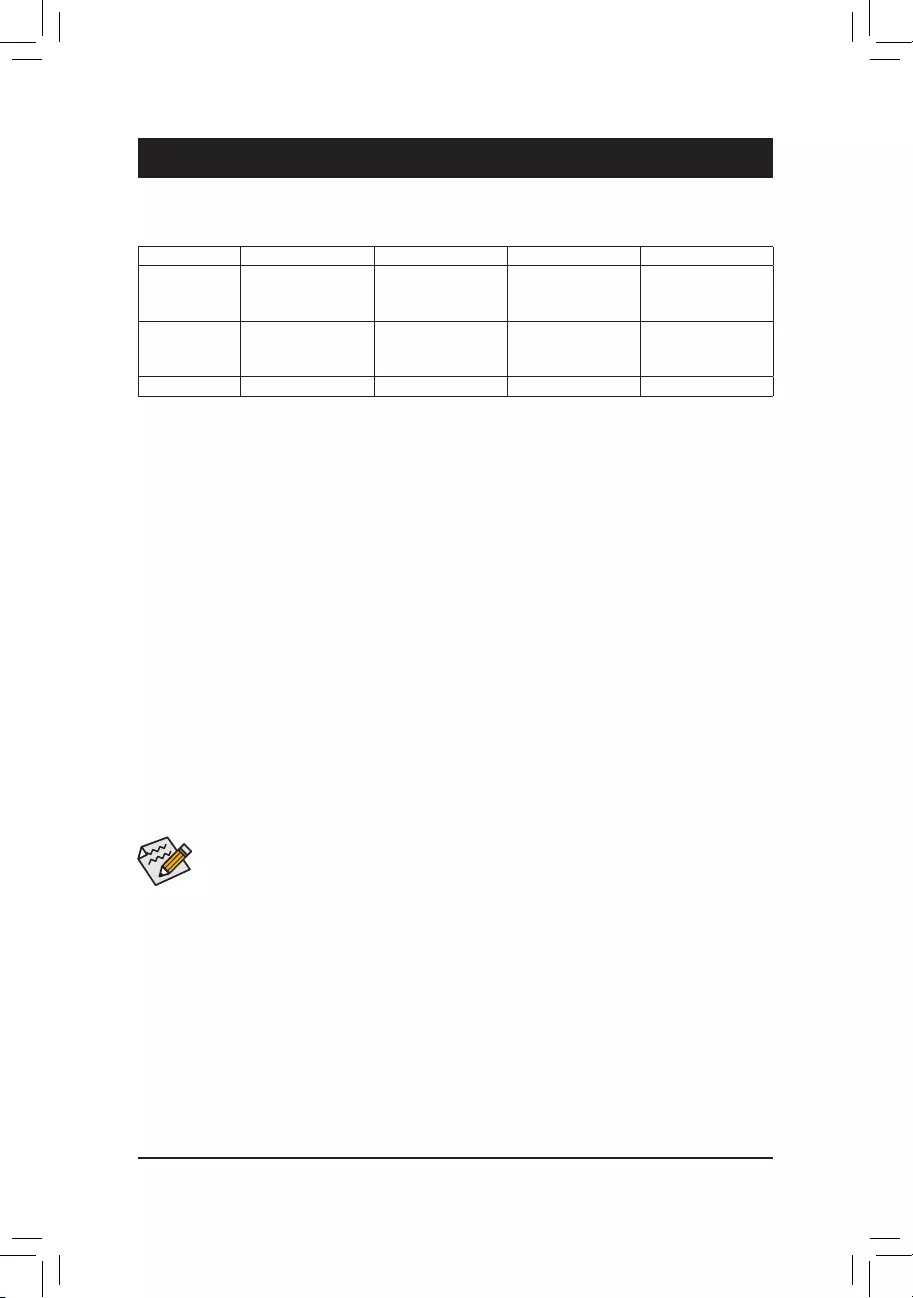
Chapter 3 Appendix
3-1 ConguringaRAIDSet
RAID Levels
Beforeyoubegin,pleasepreparethefollowingitems:
•At least two SATA hard drives or SSDs. (Note 1) (To ensure optimal performance, it is recommended that you
use two hard drives with identical model and capacity). (Note 2)
•Windows setup disc.
•Motherboard driver disc.
•A USB thumb drive.
ConguringtheOnboardSATAController
A. Installing SATA hard drive(s) in your computer
Install the hard drives/SSDs in the Intel® Chipset controlled connectors on the motherboard. Then connect the
power connectors from your power supply to the hard drives.
B.ConguringSATAcontrollermodeinBIOSSetup
MakesuretoconguretheSATAcontrollermodecorrectlyinsystemBIOSSetup.
Steps:
1. Go to PeripheralsSATAAndRSTConguration, make sure SATA Controller(s) is enabled. To create
RAID,setSATA Mode Selection to Intel RST Premium With Intel Optane System Acceleration. Then
save the settings and restart your computer. Note: When using a PCIe SSD, make sure to set the USE RST
Legacy OROM item under PeripheralsSATAAndRSTConguration to Disabled. Then depending the
M.2 connector you use, set the corresponding PCIe Storage Dev on Port XX item to RST Controlled.
2. TousetheEZRAIDfeature,followthestepsin»C-1.»TocongureUEFIRAID,followthestepsin«C-2.»To
enterthelegacyRAIDROM,referto«C-3″formoreinformation.Finally,savethesettingsandexitBIOSSetup.
The BIOS Setup menus described in this section may differ from the exact settings for your motherboard.
The actual BIOS Setup menu options you will see shall depend on the motherboard you have and
the BIOS version.
C-1. Using EZ RAID
GIGABYTEmotherboardsprovideyouwith theEZRAID feature,allowingyoutoquicklycongureaRAID
arraywithsimpliedsteps.
Steps:
1. After restarting the computer, enter the BIOS Setup and go to Peripherals. Press <Enter> on the EZ RAID
item.SelectthetypeofharddrivesyouuseforRAIDintheType tab and then press <Enter>.
2. Go to the ModetabtoselectaRAIDlevel.RAIDlevelssupportedincludeRAID0,RAID1,RAID10,andRAID
5 (the selections available depend on the number of the hard drives being installed). Then press <Enter> to
move to the Create tab. Click Proceed to begin.
(Note1) AnM.2PCIeSSDcannotbeusedtosetupaRAIDseteitherwithanM.2SATASSDoraSATAharddrive.
(Note2) Referto»1-7InternalConnectors,»fortheinstallationnoticesfortheM.2andSATAconnectors.
RAID 0 RAID 1 RAID 5 RAID 10
Minimum
Number of Hard
Drives
≥2 2≥3 4
Array Capacity Number of hard
drives*Sizeofthe
smallest drive
Sizeofthesmallest
drive
(Number of hard
drives-1)*Sizeof
the smallest drive
(Number of hard
drives/2)*Sizeofthe
smallest drive
Fault Tolerance No Yes Yes Yes
— 40 —

C-2.UEFIRAIDConguration
Steps:
1. In BIOS Setup, go to BIOS and set CSM Support to Disabled. Save the changes and exit BIOS Setup.
2. After the system reboot, enter BIOS Setup again. Then enter the PeripheralsIntel(R) Rapid Storage
Technology sub-menu.
3. On the Intel(R) Rapid Storage Technology menu, press <Enter> on Create RAID Volume to enter the
Create RAID Volumescreen.Enteravolumenamewith1~16letters(letterscannotbespecialcharacters)
under the Nameitemandpress<Enter>.Then,selectaRAIDlevel.RAIDlevelssupportedincludeRAID0,
RAID1,RAID10,andRAID5(theselectionsavailabledependonthenumberoftheharddrivesbeing
installed). Next, use the down arrow key to move to Select Disks.
4. Under Select Disksitem,selecttheharddrivestobeincludedintheRAIDarray.Pressthe<Space>key
ontheharddrivestobeselected(selectedharddrivesaremarkedwith«X»).Thensetthestripeblocksize.
Thestripeblocksizecanbesetfrom4KBto128KB.Onceyouhaveselectedthestripeblocksize,setthe
volume capacity.
5. After setting the capacity, move to Create Volume and press <Enter> to begin.
6. After completing, you’ll be brought back to the Intel(R) Rapid Storage Technology screen. Under RAID
VolumesyoucanseethenewRAIDvolume.Toseemoredetailedinformation,press<Enter>onthevolume
tocheckforinformationonRAIDlevel,stripeblocksize,arrayname,andarraycapacity,etc.
PleasevisitGIGABYTE’swebsitefordetailsonconguringaRAIDarray.
C-3.ConguringLegacyRAIDROM
Enter the Intel®legacyRAIDBIOSsetuputilitytocongureaRAIDarray.Skipthisstepandproceedwiththe
installationofWindowsoperatingsystemforanon-RAIDconguration.
Steps:
1. In BIOS Setup, go to BIOS and set CSM Support to Enabled and Storage Boot Option Control to Legacy.
Next, go to PeripheralsSATAAndRSTConguration and make sure Use RST Legacy OROM is set
to Enabled. Save the changes and exit BIOS Setup. After the POST memory test begins and before the
operatingsystembootbegins,lookforamessagewhichsays«Press<Ctrl-I>toenterCongurationUtility».
Press<Ctrl>+<I>toentertheRAIDCongurationUtility.
2. After you press <Ctrl> + <I>, the MAIN MENUscreenwillappear.IfyouwanttocreateaRAIDarray,select
Create RAID Volume in MAIN MENU and press <Enter>.
3. After entering the CREATE VOLUME MENUscreen,enteravolumenamewith1~16letters(letterscannot
be special characters) under the Nameitemandpress<Enter>.Then,selectaRAIDlevel.RAIDlevels
supportedincludeRAID0,RAID1,RAID10,andRAID5(theselectionsavailabledependonthenumberof
the hard drives being installed). Press <Enter> to proceed.
4. Under Disksitem,selecttheharddrivestobeincludedintheRAIDarray.Ifonlytwoharddrivesareinstalled,
theywillbeautomaticallyassignedtothearray.Setthestripeblocksizeifnecessary.Thestripeblocksize
canbesetfrom4KBto128KB.Onceyouhaveselectedthestripeblocksize,press<Enter>.
5. Enter the array capacity and press <Enter>. Finally press <Enter> on the Create Volume item to begin
creatingtheRAIDarray.Whenpromptedtoconrmwhethertocreatethisvolume,press<Y>toconrmor
<N> to cancel.
6. Whencompleted,youcanseedetailedinformationabouttheRAIDarrayintheDISK/VOLUME INFORMATION
section,includingtheRAIDlevel,stripeblocksize,arrayname,andarraycapacity,etc.ToexittheRAID
BIOS utility, press <Esc> or select 6. Exit in MAIN MENU.
3. After completing, you’ll be brought back to the Intel(R) Rapid Storage Technology screen. Under RAID
VolumesyoucanseethenewRAIDvolume.Toseemoredetailedinformation,press<Enter>onthevolume
tocheckforinformationonRAIDlevel,stripeblocksize,arrayname,andarraycapacity,etc.
— 41 —

(Note) If the system already has Intel®RapidStorageTechnologyutilityinstalled,youhavetoremoveitrst
beforeinstallingtheIntel(R)Optane(TM)MemorySystemAccelerationapplication.
Install the SATA RAID/AHCI driver and operating system
With the correct BIOS settings, you are ready to install the operating system.
Installing the Operating System
As some operating systems already include Intel®RAID/AHCIdriver,youdonotneedtoinstallseparateRAID/
AHCI driver during the Windows installation process. After the operating system is installed, we recommend
thatyouinstallallrequireddriversfromthemotherboarddriverdiscusing«XpressInstall»toensuresystem
performance and compatibility. If the operating system to be installed requires that you provide additional SATA
RAID/AHCIdriverduringtheOSinstallationprocess,pleaserefertothestepsbelow:
1. Copy the IRST folder under Boot in the driver disc to your USB thumb drive.
2. Boot from the Windows setup disc and perform standard OS installation steps. When the screen requesting
you to load the driver appears, select Browse.
3. ThenbrowsetotheUSBashdriveandselectthelocationofthedriver.Thelocationofthedriverisas
follows:IRSTf6py-x64
4. When a screen as shown, select Intel Chipset SATA RAID Controller and click Next to load the driver and
continue the OS installation.
3-2 Installing an Intel® Optane™ Memory
System Requirements
1. Intel® Optane™ memory
2. The Optane™ memory must have at least 16 GB capacity, and it must have equal or smaller capacity than
the hard drive/SSD to be accelerated.
3. The Optane™memorycannotbeusedtoaccelerateanexistingRAIDarray;theacceleratedharddrive/SSD
cannotbeincludedinaRAIDarray.
4. The hard drive/SSD to be accelerated must be a SATA hard drive or M.2 SATA SSD.
5. The hard drive/SSD to be accelerated can be a system drive or data drive. The system drive must be GPT
formatted and have Windows 10 64-bit (or later version) installed on it. The data drive must also be GPT
formatted.
6. The motherboard driver disc
Installation Guidelines
A-1:InstallationinAHCImode
IftheSATAcontrollerhasbeenconguredinAHCImode,pleasefollowthestepsbelow:
1. After entering the operating system, insert the motherboard driver disc into your optical drive. On the Xpress
Install screen, select Intel(R) Optane(TM) Memory System Acceleration (Note) to install. Follow the on-screen
instructions to continue. When completed, restart the system.
2. After re-entering the operating system, follow the on-screen instructions to complete the settings, and then the
Intel® Optane™ Memory application will appear automatically. If you install more than one Optane™ memory,
please select which one you are going to use. Then select which drive to be accelerated. Click Enable. All
data on the Optane™ memory will be erased. Make sure you back up the data before continuing. Follow the
on-screen instructions to proceed. When completed, restart the system.
3. Launch the Intel® Optane™ Memory application from the Start menu and make sure the Intel® Optane™
Memoryhasbeenenabled.(TheSATAcontrollermodeischangedto«IntelRSTPremiumWithIntelOptane
SystemAcceleration»fromAHCImode.DONOTchangeyourSATAcontrollermodebacktoAHCI.Doing
so will cause the Optane™ memory unable to function properly.)
4. Ifyouwanttoacceleratethesystemdrive,youcanselectspecicfolders,les,orapplicationstoaccelerate
using the Intel® Optane™ Memory Pinning function. (The Intel® Optane™ memory used must have at least
32 GB capacity.)
— 42 —

A-2:InstallationinIntelRSTPremiumWithIntelOptaneSystemAccelerationmode
IftheSATAcontrollerhasbeenconguredinIntelRSTPremiumWithIntelOptaneSystemAccelerationmode,
please follow the steps below:
1. After system restarts, go to the BIOS Setup, make sure CSM Support under the BIOS menu is disabled.
2. Go to PeripheralsSATAAndRSTConguration and make sure Use RST Legacy OROM is disabled. If
you want to enable the Optane™ memory installed in the M2M connector, set PCIe Storage Dev On Port 21
to RST Controlled; to enable the Optane™ memory installed in the M2P connector, set PCIe Storage Dev
On Port 9 to RST Controlled.
3. Enter the operating system, launch the Intel®RapidStorageTechnologyutilityfromtheStartmenu,andthen
enable Intel® Optane™ Memory on the Intel® Optane™ Memory screen.
4. If you install more than one Optane™ memory, please select which one you are going to use. Then select
which drive to be accelerated. Click Yes to continue. Follow the on-screen instructions to proceed. When
completed, restart the system.
5. Launch the Intel® Rapid Storage Technology utility from the Start menu and make sure the Intel® Optane™
Memoryhasbeenenabled.Ifyouwanttoacceleratethesystemdrive,youcanselectspecicfolders,les,or
applications to accelerate using the Intel® Optane™ Memory Pinning function. (The Intel® Optane™ memory
used must have at least 32 GB capacity.)
•An Optane™ memory cannot be used to accelerate an M.2 PCIe SSD.
•If more than one Optane™ memory is installed, you can select only one of them to accelerate your
SATA-based boot drive. The other(s) can only be used as data drive(s).
•Do not abruptly remove the Optane™ memory. Doing so will cause the operating system to stop
functioning correctly.
•If you want to change/remove the Optane™ memory, you must disable it using the Intel®Rapid
StorageTechnologyorIntel(R)Optane™Memoryapplicationrst.
•After enabling the Optane™ memory, the related BIOS settings will remain even after a BIOS update.
— 43 —
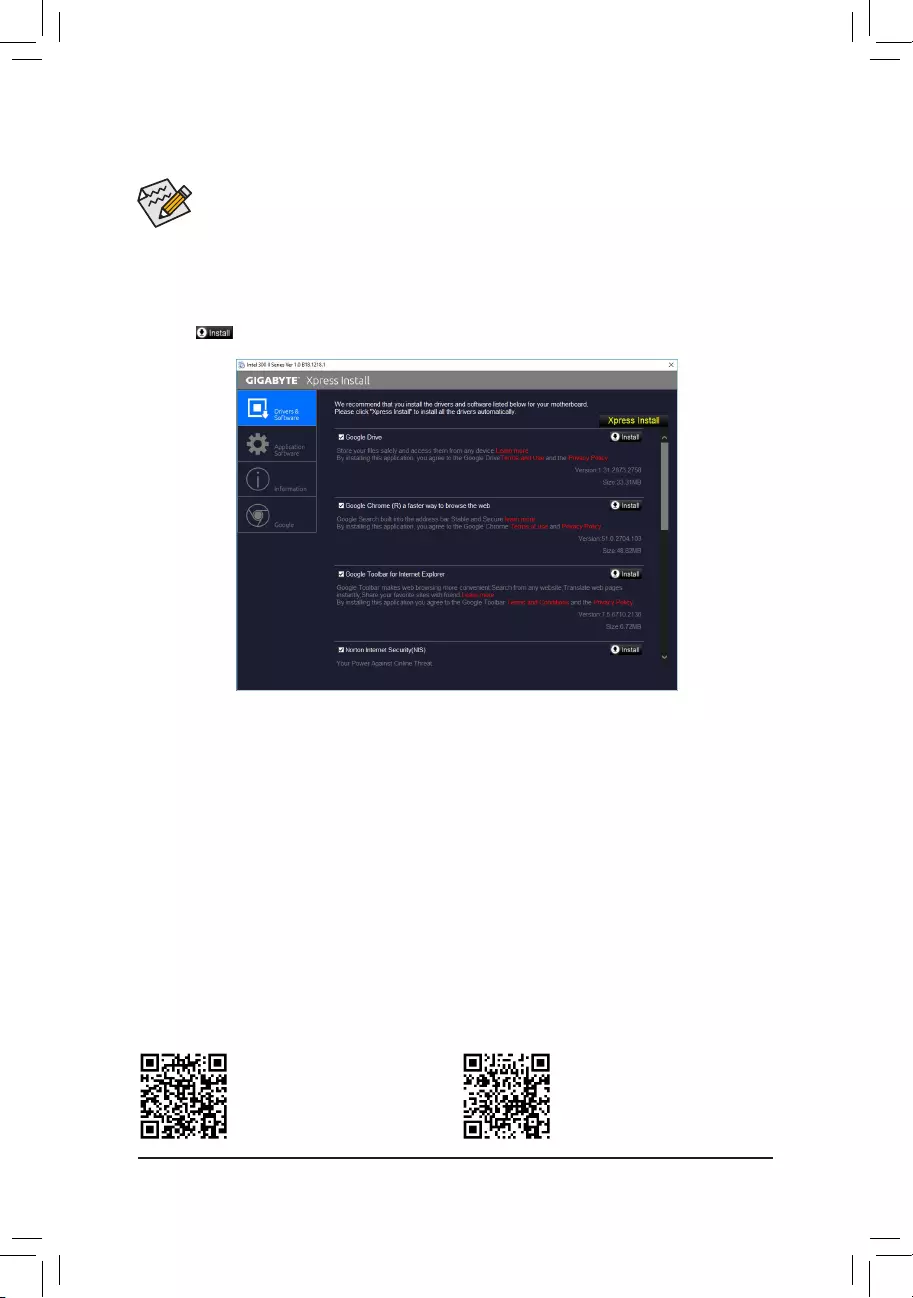
•Beforeinstallingthedrivers,rstinstalltheoperatingsystem.
•After installing the operating system, insert the motherboard driver disk into your optical drive. Click
onthemessage»Taptochoosewhathappenswiththisdisc»onthetop-rightcornerofthescreen
andselect»RunRun.exe.»(OrgotoMyComputer,double-clicktheopticaldriveandexecutethe
Run.exeprogram.)
«XpressInstall»willautomaticallyscanyoursystemandthenlistallofthedriversthatarerecommendedto
install. You can click the Xpress Installbuttonand«XpressInstall»willinstallalloftheselecteddrivers.Orclick
the arrow icon to individually install the drivers you need.
3-3 Drivers Installation
Please visit GIGABYTE’s website for
more software information.
Please visit GIGABYTE’s website for
more troubleshooting information.
— 44 —
Regulatory Statements
Regulatory Notices
This document must not be copied without our written permission, and the contents there of must not be imparted to a
thirdpartynorbeusedforanyunauthorizedpurpose.
Contravention will be prosecuted. We believe that the information contained herein was accurate in all respects at the
time of printing. GIGABYTE cannot, however, assume any responsibility for errors or omissions in this text. Also note
that the information in this document is subject to change without notice and should not be construed as a commitment
by GIGABYTE.
Our Commitment to Preserving the Environment
Inadditiontohigh-efciencyperformance,allGIGABYTEmotherboardsfulllEuropeanUnionregulationsforRoHS
(RestrictionofCertainHazardousSubstancesinElectricalandElectronicEquipment)andWEEE(WasteElectricaland
Electronic Equipment) environmental directives, as well as most major worldwide safety requirements. To prevent releases
ofharmfulsubstancesintotheenvironmentandtomaximizetheuseofournaturalresources,GIGABYTEprovidesthe
followinginformationonhowyoucanresponsiblyrecycleorreusemostofthematerialsinyour»endoflife»product.
Restriction of Hazardous Substances (RoHS) Directive Statement
GIGABYTEproductshavenotintendedtoaddandsafefromhazardoussubstances(Cd,Pb,Hg,Cr+6,PBDEand
PBB).ThepartsandcomponentshavebeencarefullyselectedtomeetRoHSrequirement.Moreover,weatGIGABYTE
are continuing our efforts to develop products that do not use internationally banned toxic chemicals.
Waste Electrical & Electronic Equipment (WEEE) Directive Statement
GIGABYTEwillfulllthenationallawsasinterpretedfromthe2012/19/EUWEEE(WasteElectricalandElectronic
Equipment)directive.TheWEEEDirectivespeciesthetreatment,collection,recyclinganddisposalofelectricand
electronic devices and their components. Under the Directive, used equipment must be marked, collected separately,
and disposed of properly.
WEEE Symbol Statement
The symbol shown below is on the product or on its packaging, which indicates that this product must
not be disposed of with other waste. Instead, the device should be taken to the waste collection centers
for activation of the treatment, collection, recycling and disposal procedure. The separate collection and
recycling of your waste equipment at the time of disposal will help to conserve natural resources and ensure
that it is recycled in a manner that protects human health and the environment. For more information about where you
candropoffyourwasteequipmentforrecycling,pleasecontactyourlocalgovernmentofce,yourhouseholdwaste
disposal service or where you purchased the product for details of environmentally safe recycling.
Whenyourelectricalorelectronicequipmentisnolongerusefultoyou,«takeitback»toyourlocalorregionalwaste
collection administration for recycling.
Ifyouneedfurtherassistanceinrecycling,reusinginyour«endoflife»product,youmaycontactusattheCustomer
Care number listed in your product’s user’s manual and we will be glad to help you with your effort.
Finally, we suggest that you practice other environmentally friendly actions by understanding and using the energy-saving
features of this product (where applicable), recycling the inner and outer packaging (including shipping containers) this
product was delivered in, and by disposing of or recycling used batteries properly. With your help, we can reduce the
amountofnaturalresourcesneededtoproduceelectricalandelectronicequipment,minimizetheuseoflandllsfor
thedisposalof«endoflife»products,andgenerallyimproveourqualityoflifebyensuringthatpotentiallyhazardous
substances are not released into the environment and are disposed of properly.
Battery Information
European Union—Disposal and recycling information
GIGABYTERecyclingProgram(availableinsomeregions)
This symbol indicates that this product and/or battery should not be disposed of with household waste. You must use
the public collection system to return, recycle, or treat them in compliance with the local regulations.
— 45 —

FCC Notice (U.S.A. Only)
This equipment has been tested and found to comply with the limits for a Class B digital device, pursuant to Part
15oftheFCCRules.Theselimitsaredesignedtoprovidereasonableprotectionagainstharmfulinterference
in a residential installation. This equipment generates, uses, and can radiate radio frequency energy and, if not
installed and used in accordance with the instructions, may cause harmful interference to radio communications.
However, there is no guarantee that interference will not occur in a particular installation. If this equipment does
cause harmful interference to radio or television reception, which can be determined by turning the equipment
off and on, the user is encouraged to try to correct the interference by one or more of the following measures:
Reorientorrelocatethereceivingantenna.
Increase the separation between the equipment and receiver.
Connect the equipment into an outlet on a circuit different from that to which the receiver is connected.
Consult a dealer or experienced TV/radio technician for help.
Canada, Industry Canada (IC) Notices / Canada, avis d‘Industry Canada (IC)
ThisClassBdigitalapparatuscomplieswithCanadianICES-003andRSS-210.
Operation is subject to the following two conditions: (1) this device may not cause interference, and (2) this
device must accept any interference, including interference that may cause undesired operation of the device.
CetappareilnumériquedeclasseBestconformeauxnormescanadiennesICES-003etRSS-210.
Son fonctionnement est soumis aux deux conditions suivantes : (1) cet appareil ne doit pas causer
d’interférence et (2) cet appareil doit accepter toute interférence, notamment les interférences qui peuvent
affecter son fonctionnement.
— 46 —

Contact Us
GIGA-BYTE TECHNOLOGY CO., LTD.
Address:No.6,BaoqiangRd.,XindianDist.,NewTaipeiCity231,Taiwan
TEL: +886—2-8912-4000, FAX: +886-2-8912-4005
Tech. and Non-Tech. Support (Sales/Marketing) : https://esupport.gigabyte.com
WEB address (English): https://www.gigabyte.com
WEB address (Chinese): https://www.gigabyte.com/tw
•GIGABYTE eSupport
To submit a technical or non-technical (Sales/Marketing) question, please link to:
https://esupport.gigabyte.com
— 47 —
Посмотреть инструкция для Gigabyte B365M HD3 бесплатно. Руководство относится к категории Материнские платы, 1 человек(а) дали ему среднюю оценку 8.6. Руководство доступно на следующих языках: английский. У вас есть вопрос о Gigabyte B365M HD3 или вам нужна помощь? Задайте свой вопрос здесь
Не можете найти ответ на свой вопрос в руководстве? Вы можете найти ответ на свой вопрос ниже, в разделе часто задаваемых вопросов о Gigabyte B365M HD3.
Какая ширина Gigabyte B365M HD3?
Какая толщина Gigabyte B365M HD3?
Инструкция Gigabyte B365M HD3 доступно в русский?
Не нашли свой вопрос? Задайте свой вопрос здесь