инструкцияGigabyte B450 Aorus M

To reduce the impacts on global warming, the packaging materials of this product
are recyclable and reusable. GIGABYTE works with you to protect the environment.
For more product details, please visit GIGABYTE’s website.
B450 AORUS M
User’s Manual
Rev. 1001
12ME-B45ARSM-1001R
Смотреть руководство для Gigabyte B450 Aorus M ниже. Все руководства на ManualsCat.com могут просматриваться абсолютно бесплатно. Нажав кнопку «Выбор языка» вы можете изменить язык руководства, которое хотите просмотреть.

MANUALSCAT | RU
Вопросы и ответы
У вас есть вопрос о Gigabyte B450 Aorus M, но вы не можете найти ответ в пользовательском руководстве? Возможно, пользователи ManualsCat.com смогут помочь вам и ответят на ваш вопрос. Заполните форму ниже — и ваш вопрос будет отображаться под руководством для Gigabyte B450 Aorus M. Пожалуйста, убедитесь, что вы опишите свои трудности с Gigabyte B450 Aorus M как можно более детально. Чем более детальным является ваш вопрос, тем более высоки шансы, что другой пользователь быстро ответит на него. Вам будет автоматически отправлено электронное письмо, чтобы проинформировать вас, когда кто-то из пользователей ответит на ваш вопрос.
Задать вопрос о Gigabyte B450 Aorus M
- Бренд:
- Gigabyte
- Продукт:
- Материнские платы
- Модель/название:
- B450 Aorus M
- Тип файла:
- Доступные языки:
- английский
Сопутствующие товары Gigabyte B450 Aorus M
 Loading…
![]()
B450 AORUS M
User’s Manual
Rev. 1001
12ME-B45ARSM-1001R
For more product details, please visit GIGABYTE’s website.
To reduce the impacts on global warming, the packaging materials of this product are recyclable and reusable. GIGABYTE works with you to protect the environment.

Motherboard
B450 AORUS M
Motherboard
B450 AORUS M
Jun. 15, 2018
Jun. 15, 2018
Copyright
© 2018 GIGA-BYTE TECHNOLOGY CO., LTD. All rights reserved.
The trademarks mentioned in this manual are legally registered to their respective owners.
Disclaimer
Information in this manual is protected by copyright laws and is the property of GIGABYTE.
ChangestothespecificationsandfeaturesinthismanualmaybemadebyGIGABYTEwithoutpriornotice.
No part of this manual may be reproduced, copied, translated, transmitted, or published in any form or by any means without GIGABYTE’s prior written permission.
In order to assist in the use of this product, carefully read the User’s Manual.
For product-related information, check on our website at: https://www.gigabyte.com
Identifying Your Motherboard Revision
The revision number on your motherboard looks like this: «REV: X.X.» For example, «REV: 1.0» means the revision of the motherboard is 1.0. Check your motherboard revision before updating motherboard BIOS, drivers, or when looking for technical information.
Example:

Table of Contents
|
B450 AORUS M Motherboard Layout…………………………………………………………………… |
4 |
|
|
Chapter 1 Hardware Installation………………………………………………………………………….. |
5 |
|
|
1-1 |
Installation Precautions…………………………………………………………………………. |
5 |
|
1-2 |
Product Specifications………………………………………………………………………….. |
6 |
|
1-3 |
Installing the CPU………………………………………………………………………………… |
9 |
|
1-4 |
Installing the Memory……………………………………………………………………………. |
9 |
|
1-5 Installing an Expansion Card……………………………………………………………….. |
10 |
|
|
1-6 |
Back Panel Connectors………………………………………………………………………. |
10 |
|
1-7 |
Internal Connectors……………………………………………………………………………. |
12 |
|
Chapter 2 BIOS Setup……………………………………………………………………………………… |
21 |
|
|
2-1 |
Startup Screen…………………………………………………………………………………… |
21 |
|
2-2 |
The Main Menu………………………………………………………………………………….. |
22 |
|
2-3 |
M.I.T…………………………………………………………………………………………………. |
23 |
|
2-4 |
System……………………………………………………………………………………………… |
27 |
|
2-5 |
BIOS………………………………………………………………………………………………… |
28 |
|
2-6 |
Peripherals………………………………………………………………………………………… |
31 |
|
2-7 |
Chipset……………………………………………………………………………………………… |
33 |
|
2-8 |
Power……………………………………………………………………………………………….. |
35 |
|
2-9 |
Save & Exit……………………………………………………………………………………….. |
37 |
|
Chapter 3 Appendix…………………………………………………………………………………………. |
38 |
|
|
3-1 Configuring a RAID Set………………………………………………………………………. |
38 |
|
|
3-2 |
Drivers Installation……………………………………………………………………………… |
40 |
|
Regulatory Statements…………………………………………………………………………………. |
41 |
|
|
Contact Us………………………………………………………………………………………………….. |
44 |
— 3 —
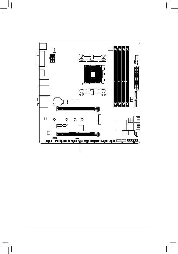
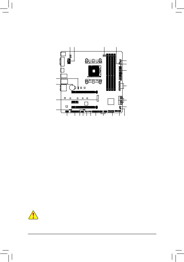
B450 AORUS M Motherboard Layout
KB_MS_USB

 SYS_FAN1
Socket AM4
HDMI
R_USB30
|
USB31_LAN |
LED CPU |
B BIOS |
||||
|
AUDIO |
M_BIOS |
|||||
|
BAT |
B450 AORUS M |
|||||
|
PCIEX16 |
||||||
|
Realtek® |
||||||
|
GbE LAN |
110 |
80 |
60 |
42 |
||
|
PCIEX1 |
iTE® |
|||||
|
CODEC |
PCIEX4 |
Super I/O |
||||
|
SPDIF_O |
DLED_V_SW1 |
|
SYS FAN2 |
||
|
V SW2 |
D_LED2 |
|
|
DLED |
||
ATX
|
1 |
|
|
0 |
|
|
DDR4 4 DDR4 2 DDR4 3 DDR4 1 ASATA3 |
|
|
2 3 |
|
|
0 1 |
|
|
AMD B450 |
SATA3 |
CPU DRAM
VGA BOOT 

CLR_CMOS 
|
F_AUDIO |
LPT |
COMA |
LED |
_C TPM F_USB1 F_USB2 F_USB30 F_PANEL |
D_LED1
Box Contents
|
55 |
B450 AORUS M Motherboard |
55 |
Two SATA cables |
|
55 |
Motherboard driver disk |
55 |
I/O Shield |
|
55 |
User’s Manual |
55 |
M.2 screw(s)/M.2 standoff(s) |
*The box contents above are for reference only and the actual items shall depend on the product package you obtain. The box contents are subject to change without notice.
—4 —

Chapter 1 Hardware Installation
1-1 Installation Precautions
The motherboard contains numerous delicate electronic circuits and components which can become damaged as a result of electrostatic discharge (ESD). Prior to installation, carefully read the user’s manual and follow these procedures:
•• Prior to installation, make sure the chassis is suitable for the motherboard.
•• Prior to installation, do not remove or break motherboard S/N (Serial Number) sticker or warranty sticker provided by your dealer. These stickers are required for warranty validation.
•• Always remove the AC power by unplugging the power cord from the power outlet before installing or removing the motherboard or other hardware components.
•• When connecting hardware components to the internal connectors on the motherboard, make sure they are connected tightly and securely.
•• When handling the motherboard, avoid touching any metal leads or connectors.
•• It is best to wear an electrostatic discharge (ESD) wrist strap when handling electronic components such as a motherboard, CPU or memory. If you do not have an ESD wrist strap, keep your hands dry and first touch a metal object to eliminate static electricity.
•• Prior to installing the motherboard, please have it on top of an antistatic pad or within an electrostatic shielding container.
•• Before connecting or unplugging the power supply cable from the motherboard, make sure the power supply has been turned off.
•• Before turning on the power, make sure the power supply voltage has been set according to the local voltage standard.
•• Before using the product, please verify that all cables and power connectors of your hardware components are connected.
•• To prevent damage to the motherboard, do not allow screws to come in contact with the motherboard circuit or its components.
•• Make sure there are no leftover screws or metal components placed on the motherboard or within the computer casing.
•• Do not place the computer system on an uneven surface.
•• Do not place the computer system in a high-temperature or wet environment.
•• Turning on the computer power during the installation process can lead to damage to system components as well as physical harm to the user.
•• If you are uncertain about any installation steps or have a problem related to the use of the product, please consult a certified computer technician.
•• If you use an adapter, extension power cable, or power strip, ensure to consult with its installation and/or grounding instructions.
— 5 —
1-2 Product Specifications
|
CPU |
AM4 Socket: |
|
— AMD Ryzen™ 2nd Generation processors |
—AMD Ryzen™ with Radeon™ Vega Graphics processors
—AMD Ryzen™ 1st Generation processors
(Go to GIGABYTE’s website for the latest CPU support list.)
|
Chipset |
AMD B450 |
|
|
Memory |
4 x DDR4 DIMM sockets supporting up to 64 GB of system memory |
|
|
Dual channel memory architecture |
||
|
Support for DDR4 2933/2667/2400/2133 MHz memory modules |
||
|
Support for ECC Un-buffered DIMM 1Rx8/2Rx8 memory modules (operate in |
||
|
non-ECC mode) |
||
|
Support for non-ECC Un-buffered DIMM 1Rx8/2Rx8/1Rx16 memory modules |
||
|
Support for Extreme Memory Profile (XMP) memory modules |
||
|
(Go to GIGABYTE’s website for the latest supported memory speeds and memory |
||
|
modules.) |
||
|
Onboard |
Integrated Graphics Processor: |
|
|
Graphics (Note) |
— 1 x DVI-D port, supporting a maximum resolution of 1920×1200@60 Hz |
*The DVI-D port does not support D-Sub connection by adapter.
—1 x HDMI port, supporting a maximum resolution of 4096×2160@60 Hz(Note)
*Support for HDMI 2.0 version and HDCP 2.2.(Note)
Maximum shared memory of 16 GB
|
Audio |
Realtek® ALC892 codec |
|
|
High Definition Audio |
||
|
2/4/5.1/7.1-channel |
||
|
Support for S/PDIF Out |
||
|
LAN |
Realtek® GbE LAN chip (10/100/1000 Mbit) |
|
|
Expansion Slots |
1 x PCI Express x16 slot, running at x16 (PCIEX16) (Note) |
|
|
* For optimum performance, if only one PCI Express graphics card is to be installed, |
||
|
be sure to install it in the PCIEX16 slot. |
||
|
(The PCIEX16 slot conforms to PCI Express 3.0 standard.) |
||
|
1 x PCI Express x16 slot, running at x4 (PCIEX4) |
||
|
1 x PCI Express x1 slot |
||
|
(The PCIEX4 and PCIEX1 slots conform to PCI Express 2.0 standard.) |
||
|
Multi-Graphics |
SupportforAMDQuad-GPUCrossFire™ and2-WayAMDCrossFire™ technologies |
|
|
Technology |
Storage Interface 1 x M.2 connector (Socket 3, M key, type 2242/2260/2280/22110 SATA and
PCIe 3.0 x4/x2 SSD support)
6 x SATA 6Gb/s connectors
Support for RAID 0, RAID 1, and RAID 10
*Refer to «1-7 Internal Connectors,» for the installation notices for the M.2 and SATA connectors.
(Note) Actual support may vary by CPU.
— 6 —
|
USB |
Chipset: |
|
|
— 2 x USB 3.1 Gen 2 Type-A ports (red) on the back panel |
||
|
— |
2 x USB 3.1 Gen 1 ports available through the internal USB header |
|
|
— |
6 x USB 2.0/1.1 ports (2 ports on the back panel, 4 ports available through |
the internal USB headers)CPU:
—4 x USB 3.1 Gen 1 ports on the back panel
|
Internal |
1 x 24-pin ATX main power connector |
|
|
Connectors |
1 x 8-pin ATX 12V power connector |
|
|
1 x CPU fan header |
||
|
2 x system fan headers |
||
|
1 x M.2 Socket 3 connector |
||
|
6 x SATA 6Gb/s connectors |
||
|
1 x CPU cooler LED strip/RGB LED strip header |
||
|
1 x RGB (RGBW) LED strip header |
||
|
2 x digital LED strip headers |
||
|
2 x digital LED strip power select jumpers |
||
|
1 x front panel header |
||
|
1 x front panel audio header |
||
|
1 x S/PDIF Out header |
||
|
1 x USB 3.1 Gen 1 header |
||
|
2 x USB 2.0/1.1 headers |
||
|
1 x Trusted Platform Module (TPM) header (2×10 pin, for the GC-TPM2.0 module |
||
|
only) |
||
|
1 x serial port header |
||
|
1 x parallel port header |
||
|
1 x Clear CMOS jumper |
||
|
Back Panel |
1 x PS/2 keyboard/mouse port |
|
|
Connectors |
1 x DVI-D port |
|
|
1 x HDMI port |
||
|
2 x USB 3.1 Gen 2 Type-A ports (red) |
||
|
4 x USB 3.1 Gen 1 ports |
||
|
2 x USB 2.0/1.1 ports |
||
|
1 x RJ-45 port |
||
|
6 x audio jacks |
||
|
I/O Controller |
iTE® I/O Controller Chip |
|
|
Hardware |
Voltage detection |
|
|
Monitor |
Temperature detection |
|
|
Fan speed detection |
||
|
Overheating warning |
||
|
Fan fail warning |
||
|
Fan speed control |
*Whether the fan speed control function is supported will depend on the cooler you install.
— 7 —
|
BIOS |
2 x 128 Mbit flash |
|||
|
Use of licensed AMI UEFI BIOS |
||||
|
Support for DualBIOS™ |
||||
|
PnP 1.0a, DMI 2.7, WfM 2.0, SM BIOS 2.7, ACPI 5.0 |
||||
|
Unique Features |
Support for APP Center |
|||
|
* Available applications in APP Center may vary by motherboard model. Supported |
||||
|
functionsofeachapplicationmayalsovarydependingonmotherboardspecifications. |
||||
|
— |
3D OSD |
|||
|
— |
@BIOS |
|||
|
— |
AutoGreen |
|||
|
— |
Cloud Station |
|||
|
— |
EasyTune |
|||
|
— |
Fast Boot |
|||
|
— |
Game Boost |
|||
|
— |
ON/OFF Charge |
|||
|
— |
RGB Fusion |
|||
|
— |
Smart Backup |
|||
|
— |
Smart Keyboard |
|||
|
— |
Smart TimeLock |
|||
|
— |
Smart HUD |
|||
|
— |
Smart Survey |
|||
|
— |
System Information Viewer |
|||
|
— |
USB Blocker |
|||
|
— |
V-Tuner |
|||
|
Support for Q-Flash |
||||
|
Support for Xpress Install |
||||
|
Bundled |
Norton® Internet Security (OEM version) |
|||
|
Software |
Realtek® 8118 Gaming LAN Bandwidth Control Utility |
|||
|
Operating |
Support for Windows 10 64-bit |
|||
|
System |
||||
|
Form Factor |
Micro ATX Form Factor; 24.4cm x 24.4cm |
*GIGABYTE reserves the right to make any changes to the product specifications and product-related information without prior notice.
Please visit GIGABYTE’s website for support lists of CPU, memory modules, SSDs, and M.2 devices.
Please visit the SupportUtility List page on GIGABYTE’s website to download the latest version of apps.
— 8 —
|
1-3 |
Installing the CPU |
||||
|
Read the following guidelines before you begin to install the CPU: |
|||||
|
•• |
Make sure that the motherboard supports the CPU. |
||||
|
(Go to GIGABYTE’s website for the latest CPU support list.) |
|||||
|
•• |
Always turn off the computer and unplug the power cord from the power outlet before installing the |
||||
|
•• |
CPU to prevent hardware damage. |
||||
|
Locate the pin one of the CPU. The CPU cannot be inserted if oriented incorrectly. |
|||||
|
•• |
Apply an even and thin layer of thermal grease on the surface of the CPU. |
||||
|
•• |
Do not turn on the computer if the CPU cooler is not installed, otherwise overheating and damage |
||||
|
•• |
of the CPU may occur. |
||||
|
Set the CPU host frequency in accordance with the CPU specifications. It is not recommended |
|||||
|
that the system bus frequency be set beyond hardware specifications since it does not meet the |
|||||
|
standard requirements for the peripherals. If you wish to set the frequency beyond the standard |
|||||
|
specifications, please do so according to your hardware specifications including the CPU, graphics |
|||||
|
card, memory, hard drive, etc. |
|||||
|
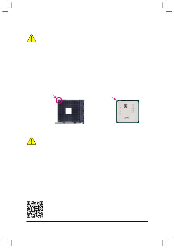
Installing the CPU |
|||||
|
Locate the pin one (denoted by a small triangle) of the CPU socket and the CPU. |
|||||
|
A Small Triangle Marking |
A Small Triangle Marking |
||||
|
Denotes Pin One of the |
AM4 Socket |
AM4 CPU |
|||
|
Denotes CPU Pin One |
|||||
|
Socket |
1-4 Installing the Memory
Read the following guidelines before you begin to install the memory:
•• Make sure that the motherboard supports the memory. It is recommended that memory of the same capacity, brand, speed, and chips be used.
(Go to GIGABYTE’s website for the latest supported memory speeds and memory modules.)
•• Always turn off the computer and unplug the power cord from the power outlet before installing the memory to prevent hardware damage.
•• Memory modules have a foolproof design. A memory module can be installed in only one direction. If you are unable to insert the memory, switch the direction.
Dual Channel Memory Configuration
This motherboard provides four memory sockets and supports Dual Channel Technology. After the memory is installed, the BIOS will automatically detect the specifications and capacity of the memory. Enabling Dual
Channel memory mode will double the original memory bandwidth.
The four memory sockets are divided into two channels and each channel has two memory sockets as following:
Channel A: DDR4_2, DDR4_4Channel B: DDR4_1, DDR4_3
Please visit GIGABYTE’s website for details on hardware installation.
— 9 —
Dual Channel Memory Configurations Table
|
DDR4_4 |
DDR4_2 |
DDR4_3 |
DDR4_1 |
|
|
2 Modules |
— — |
DS/SS |
— — |
DS/SS |
|
DS/SS |
— — |
DS/SS |
— — |
|
|
4 Modules |
DS/SS |
DS/SS |
DS/SS |
DS/SS |
(SS=Single-Sided, DS=Double-Sided, «- -«=No Memory)
Due to CPU limitations, read the following guidelines before installing the memory in Dual Channel mode.
1.Dual Channel mode cannot be enabled if only one memory module is installed.
2.WhenenablingDualChannelmodewithtwoorfourmemorymodules,itisrecommendedthatmemory of the same capacity, brand, speed, and chips be used. For optimum performance, when enabling
Dual Channel mode with two memory modules, we recommend that you install them in the DDR4_1 and DDR4_2 sockets.
1-5 Installing an Expansion Card
Read the following guidelines before you begin to install an expansion card:
•• Make sure the motherboard supports the expansion card. Carefully read the manual that came with your expansion card.
•• Always turn off the computer and unplug the power cord from the power outlet before installing an expansion card to prevent hardware damage.
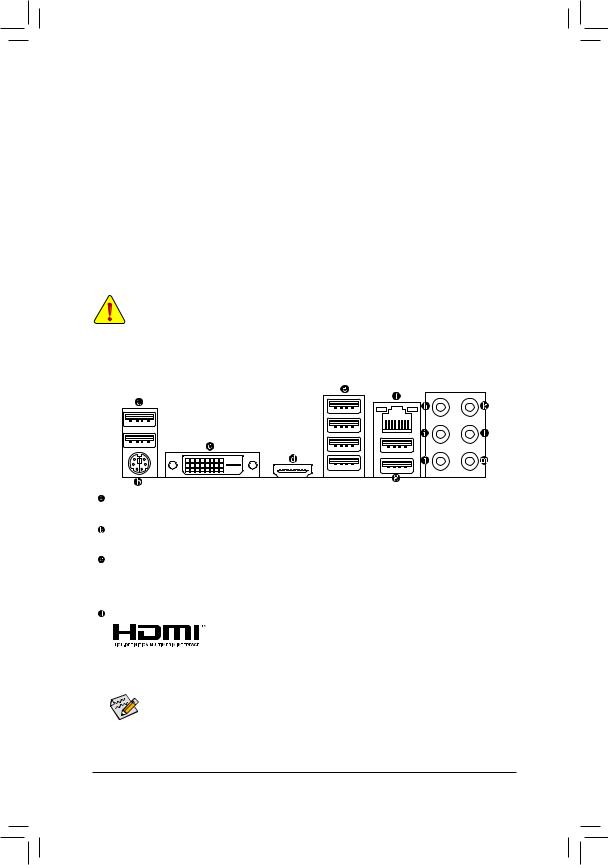
1-6 Back Panel Connectors
USB 2.0/1.1 Port
The USB port supports the USB 2.0/1.1 specification. Use this port for USB devices.
PS/2 Keyboard/Mouse Port
Use this port to connect a PS/2 mouse or keyboard.
DVI-D Port (Note 1)
The DVI-D port conforms to the DVI-D specification and supports a maximum resolution of 1920×1200@60 Hz
(the actual resolutions supported depend on the monitor being used). Connect a monitor that supports
DVI-D connection to this port.
HDMI Port
|
The HDMI port supports HDCP 2.2 (Note 2) and Dolby TrueHD and DTS HD |
|
Master Audio formats. It also supports up to 192KHz/24bit 8-channel LPCM |
|
audio output. You can use this port to connect your HDMI-supported monitor. The maximum supported |
resolution is 4096×2160@60 Hz (Note 2), but the actual resolutions supported are dependent on the monitor being used.
After installing the HDMI device, make sure to set the default sound playback device to HDMI. (The item name may differ depending on your operating system.)
(Note 1) The DVI-D port does not support D-Sub connection by adapter.
(Note 2) Actual support may vary by CPU.
— 10 —
![]()
USB 3.1 Gen 1 Port
The USB 3.1 Gen 1 port supports the USB 3.1 Gen 1 specification and is compatible to the USB 2.0 specification. Use this port for USB devices.
RJ-45 LAN Port
The Gigabit Ethernet LAN port provides Internet connection at up to 1 Gbps data rate. The following describes the states of the LAN port LEDs.
|
Connection/ |
Activity LED |
Connection/Speed LED: |
Activity LED: |
||||||||||||||
|
Speed LED |
|||||||||||||||||
|
State |
Description |
State |
Description |
||||||||||||||
|
Orange |
1 Gbps data rate |
Blinking |
Data transmission or receiving is occurring |
||||||||||||||
|
Green |
100 Mbps data rate |
Off |
No data transmission or receiving is occurring |
||||||||||||||
|
Off |
10 Mbps data rate |
||||||||||||||||
|
LAN Port |
|||||||||||||||||
USB 3.1 Gen 2 Type-A Port (Red)
The USB 3.1 Gen 2 Type-A port supports the USB 3.1 Gen 2 specification and is compatible to the USB 3.1 Gen 1 and USB 2.0 specification. Use this port for USB devices.
Center/Subwoofer Speaker Out (Orange)
Use this audio jack to connect center/subwoofer speakers.
Rear Speaker Out (Black)
Use this audio jack to connect rear speakers.
Side Speaker Out (Gray)
Use this audio jack to connect side speakers.
Line In (Blue)
The line in jack. Use this audio jack for line in devices such as an optical drive, walkman, etc.
Line Out/Front Speaker Out (Green)
The line out jack.
Mic In (Pink)
The Mic in jack.
Audio Jack Configurations:
|
Jack |
Headphone/ |
4-channel |
5.1-channel |
7.1-channel |
|
|
2-channel |
|||||
|
Center/Subwoofer Speaker Out |
a |
a |
|||
|
Rear Speaker Out |
a |
a |
a |
||
|
Side Speaker Out |
a |
||||
|
Line In |
|||||
|
Line Out/Front Speaker Out |
a |
a |
a |
a |
|
|
Mic In |
•• When removing the cable connected to a back panel connector, first remove the cable from your device and then remove it from the motherboard.
•• When removing the cable, pull it straight out from the connector. Do not rock it side to side to prevent an electrical short inside the cable connector.
Please visit GIGABYTE’s website for details on configuring the audio software.
— 11 —
1-7 Internal Connectors
|
4 |
|
|
7 |
|
|
2 |
|
|
5 |
|
|
11 |
9 |
|
12 |
10 |
|
14 |
22 |
|
15 |
20 |
8 |
19 |
7 |
6 |
18 |
17 |
16 |
13 |
21 |
|
1) |
ATX_12V |
12) |
M2A_SOCKET |
|
2) |
ATX |
13) |
F_PANEL |
|
3) |
CPU_FAN |
14) |
SPDIF_O |
|
4) |
SYS_FAN1/2 |
15) |
F_AUDIO |
|
5) |
LED_CPU |
16) |
F_USB30 |
|
6) |
LED_C |
17) |
F_USB1/F_USB2 |
|
7) |
D_LED1/D_LED2 |
18) |
TPM |
|
|
DLED_V_SW1/DLED_V_SW2 |
19) |
COMA |
|
9) |
ASATA3 0/1 |
20) |
LPT |
|
10) |
SATA3 0/1/2/3 |
21) |
CLR_CMOS |
|
11) |
BAT |
22) |
CPU/DRAM/VGA/BOOT |

Read the following guidelines before connecting external devices:
•• First make sure your devices are compliant with the connectors you wish to connect.
•• Before installing the devices, be sure to turn off the devices and your computer. Unplug the power cord from the power outlet to prevent damage to the devices.
•• After installing the device and before turning on the computer, make sure the device cable has been securely attached to the connector on the motherboard.
— 12 —
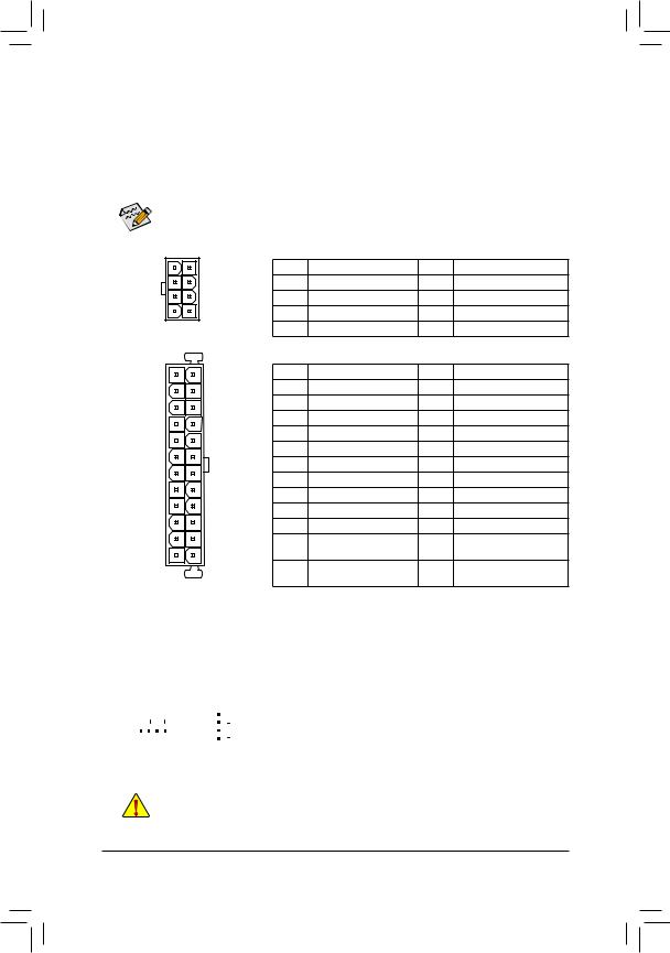
1/2) ATX_12V/ATX (2×4 12V Power Connector and 2×12 Main Power Connector)
Withtheuseofthepowerconnector,thepowersupplycansupplyenoughstablepowertoallthecomponents on the motherboard. Before connecting the power connector, first make sure the power supply is turned off and all devices are properly installed. The power connector possesses a foolproof design. Connect the power supply cable to the power connector in the correct orientation.
The 12V power connector mainly supplies power to the CPU. If the 12V power connector is not connected, the computer will not start.
To meet expansion requirements, it is recommended that a power supply that can withstand high power consumption be used (500W or greater). If a power supply is used that does not provide the required power, the result can lead to an unstable or unbootable system.
|
ATX_12V: |
|||||
|
8 |
4 |
Pin No. |
Definition |
Pin No. |
Definition |
|
1 |
GND (Only for 2×4-pin 12V) |
5 |
+12V (Only for 2×4-pin 12V) |
||
|
2 |
GND (Only for 2×4-pin 12V) |
6 |
+12V (Only for 2×4-pin 12V) |
||
|
5 |
1 |
3 |
GND |
7 |
+12V |
|
ATX_12V |
4 |
GND |
8 |
+12V |
|
|
ATX: |
|||||
|
12 |
24 |
Pin No. |
Definition |
Pin No. |
Definition |
|
1 |
3.3V |
13 |
3.3V |
||
|
2 |
3.3V |
14 |
-12V |
||
|
3 |
GND |
15 |
GND |
||
|
4 |
+5V |
16 |
PS_ON (soft On/Off) |
||
|
5 |
GND |
17 |
GND |
||
|
6 |
+5V |
18 |
GND |
||
|
7 |
GND |
19 |
GND |
||
|
8 |
Power Good |
20 |
NC |
||
|
9 |
5VSB (stand by +5V) |
21 |
+5V |
||
|
10 |
+12V |
22 |
+5V |
||
|
11 |
+12V (Only for 2×12-pin |
23 |
+5V (Only for 2×12-pin ATX) |
||
|
1 |
13 |
12 |
ATX) |
24 |
GND (Only for 2×12-pinATX) |
|
3.3V (Only for 2×12-pin |
|||||
|
ATX |
ATX) |
||||
3/4) CPU_FAN/SYS_FAN1/2 (Fan Headers)
All fan headers on this motherboard are 4-pin. Most fan headers possess a foolproof insertion design.
When connecting a fan cable, be sure to connect it in the correct orientation (the black connector wire is the ground wire). The motherboard supports CPU fan speed control, which requires the use of a CPU fan with fan speed control design. For optimum heat dissipation, it is recommended that a system fan be installed inside the chassis.
|
Pin No. |
Definition |
||||||
|
1 |
1 |
GND |
|||||
|
1 |
2 |
Voltage Speed Control |
|||||
|
CPU_FAN |
SYS_FAN1/2 |
3 |
Sense |
||||
|
4 |
PWM Speed Control |
•• Be sure to connect fan cables to the fan headers to prevent your CPU and system from overheating. Overheating may result in damage to the CPU or the system may hang.
•• Thesefanheadersarenotconfigurationjumperblocks.Donotplaceajumpercapontheheaders.
— 13 —
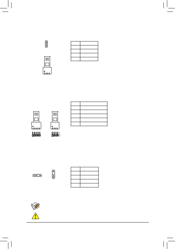
5)LED_CPU (CPU Cooler LED Strip/RGB LED Strip Header)
TheheadercanbeusedtoconnectaCPUcoolerLEDstriporastandard5050RGBLEDstrip(12V/G/R/B), with maximum power rating of 2A (12V) and maximum length of 2m.
1 
RGB
LED Strip
1 
12V
|
Pin No. |
Definition |
|
1 |
12V |
|
2 |
G |
|
3 |
R |
|
4 |
B |
Connect the CPU cooler LED strip/RGB LED strip to the header. The power pin (marked with a triangle on the plug) of the LED strip must be connected to Pin 1 (12V) of this header. Incorrect connection may lead to the damage of the LED strip.
6)LED_C (RGB (RGBW) LED Strip Header)
Theheadercanbeusedtoconnectastandard5050RGB(RGBW)LEDstrip(12V/G/R/B/W),withmaximum power rating of 2A (12V) and maximum length of 2m.
1 


|
RGBW |
RGB |
|
LED Strip |
LED Strip |
|
1 |
1 |
|
12V |
12V |
Pin No. Definition
112V
2G
3R
4B
5W
Connect your RGB (RGBW) LED strip to the header. The power pin (marked with a triangle on the plug) of the LED strip must be connected to Pin 1 (12V) of this header. Incorrect connection may lead to the damage of the LED strip.
7)D_LED1/D_LED2 (Digital LED Strip Headers)
The headers can be used to connect a standard 5050 digital LED strip, with maximum power rating of 2A (12V or 5V) and maximum number of 300 LEDs. There are 12V and 5V digital LED strips. Be sure to verify the voltage requirements of your digital LED strip and set the DLED_V_SW1 and DLED_V_SW2 jumpers accordingly.
|
Pin No. |
Definition |
|||
|
1 |
1 |
V |
||
|
1 |
2 |
D |
||
|
D_LED1 |
||||
|
D_LED2 |
3 |
No Pin |
||
|
4 |
G |
ConnectyourdigitalLEDstriptotheheader. There are 12V and 5V digital LED strips.
Be sure to verify the voltage requirements of your digital LED strip and set the DLED_V_SW1andDLED_V_SW2jumpers accordingly. The power pin (marked with a
triangle on the plug) of the LED strip must beconnectedtoPin1ofthedigitalLEDstrip header. Incorrect connection may lead to the damage of the LED strip.

 For how to turn on/off the lights of the LED strip, refer to the instructions on in Chapter 2, «BIOS
Setup,» «Peripherals.»
Before installing the devices, be sure to turn off the devices and your computer. Unplug the power cord from the power outlet to prevent damage to the devices.
— 14 —
- Manuals
- Brands
- Gigabyte Manuals
- Motherboard
- B450 AORUS ELITE V2
- User manual
-
Contents
-
Table of Contents
-
Bookmarks
Quick Links
B450 AORUS ELITE V2
User’s Manual
Rev. 1101
12ME-B45AET2-1101R
For more product details, please visit GIGABYTE’s website.
To reduce the impacts on global warming, the packaging materials of this product
are recyclable and reusable. GIGABYTE works with you to protect the environment.
Related Manuals for Gigabyte B450 AORUS ELITE V2
Summary of Contents for Gigabyte B450 AORUS ELITE V2
-
Page 1
B450 AORUS ELITE V2 User’s Manual Rev. 1101 12ME-B45AET2-1101R For more product details, please visit GIGABYTE’s website. To reduce the impacts on global warming, the packaging materials of this product are recyclable and reusable. GIGABYTE works with you to protect the environment. -
Page 2
The trademarks mentioned in this manual are legally registered to their respective owners. Disclaimer Information in this manual is protected by copyright laws and is the property of GIGABYTE. Changes to the specifications and features in this manual may be made by GIGABYTE without prior notice. -
Page 3: Table Of Contents
Table of Contents B450 AORUS ELITE V2 Motherboard Layout …………..4 Chapter 1 Hardware Installation ………………5 Installation Precautions ………………5 1-2 Product Specifications ………………6 Installing the CPU ……………….. 9 Installing the Memory ………………9 Installing an Expansion Card …………….. 10 Back Panel Connectors ……………… 10 Internal Connectors ………………
-
Page 4: B450 Aorus Elite V2 Motherboard Layout
B450 AORUS ELITE V2 Motherboard Layout ATX_12V KB_MS_USB CPU_FAN Socket AM4 R_USB30 USB_LAN SYS_FAN1 LED_CPU AUDIO M_BIOS PCIEX1_1 B450 AORUS ELITE V2 PCIEX16 Realtek ® GbE LAN AMD B450 PCIEX4 CODEC CPU DRAM VGA BOOT ® Super I/O PCIEX1_2 DLED_V_SW1 SPDIF_O…
-
Page 5: Chapter 1 Hardware Installation
Chapter 1 Hardware Installation Installation Precautions The motherboard contains numerous delicate electronic circuits and components which can become damaged as a result of electrostatic discharge (ESD). Prior to installation, carefully read the user’s manual and follow these procedures: • Prior to installation, make sure the chassis is suitable for the motherboard. • Prior to installation, do not remove or break motherboard S/N (Serial Number) sticker or warranty sticker provided by your dealer.
-
Page 6: 1-2 Product Specifications
Š S upport for ECC Un-buffered DIMM 1Rx8/2Rx8 memory modules (operate in Š non-ECC mode) Support for non-ECC Un-buffered DIMM 1Rx8/2Rx8/1Rx16 memory modules Š Support for Extreme Memory Profile (XMP) memory modules Š (Go to GIGABYTE’s website for the latest supported memory speeds and memory modules.) Onboard Integrated Graphics Processor: Š Graphics 1 x DVI-D port, supporting a maximum resolution of 1920×1200@60 Hz (Note) * The DVI-D port does not support D-Sub connection by adapter.
-
Page 7
Storage Interface Š 1 x M.2 connector (Socket 3, M key, type 2242/2260/2280/22110 SATA and PCIe 3.0 x4/x2 SSD support) (M2A_SOCKET) 1 x M.2 connector (Socket 3, M key, type 2242/2260/2280 PCIe 3.0 x2 SSD Š support) (M2B_SOCKET) 6 x SATA 6Gb/s connectors Š… -
Page 8
ATX Form Factor; 30.5cm x 23.5cm Š * GIGABYTE reserves the right to make any changes to the product specifications and product-related information without prior notice. Please visit the SupportUtility List Please visit GIGABYTE’s website for support lists of CPU, memory page on GIGABYTE’s website to modules, SSDs, and M.2 devices. download the latest version of apps. — 8 -… -
Page 9: Installing The Cpu
• Make sure that the motherboard supports the memory. It is recommended that memory of the same capacity, brand, speed, and chips be used. (Go to GIGABYTE’s website for the latest supported memory speeds and memory modules.) • Always turn off the computer and unplug the power cord from the power outlet before installing the memory to prevent hardware damage.
-
Page 10: Installing An Expansion Card
Dual Channel Memory Configurations Table DDR4_4 DDR4_2 DDR4_3 DDR4_1 2 Modules DS/SS DS/SS DS/SS DS/SS 4 Modules DS/SS DS/SS DS/SS DS/SS (SS=Single-Sided, DS=Double-Sided, «- -«=No Memory) Due to CPU limitations, read the following guidelines before installing the memory in Dual Channel mode. Dual Channel mode cannot be enabled if only one memory module is installed. When enabling Dual Channel mode with two or four memory modules, it is recommended that memory of the same capacity, brand, speed, and chips be used. For optimum performance, when enabling Dual Channel mode with two memory modules, we recommend that you install them in the DDR4_1 and DDR4_2 sockets. Installing an Expansion Card Read the following guidelines before you begin to install an expansion card: •…
-
Page 11
Side Speaker Out Line In Line Out/Front Speaker Out Mic In To enable or configure the audio amplifying function for the Line out jack, please access the HD Audio Manager application. • When removing the cable connected to a back panel connector, first remove the cable from your device and then remove it from the motherboard. • When removing the cable, pull it straight out from the connector. Do not rock it side to side to prevent an electrical short inside the cable connector. Please visit GIGABYTE’s website for details on configuring the audio software. — 11 -… -
Page 12: Internal Connectors
Internal Connectors ATX_12V SPDIF_O F_PANEL CPU_FAN F_AUDIO SYS_FAN1/2/3 LED_CPU CLR_CMOS LED_C F_USB30 D_LED1/D_LED2 F_USB1/F_USB2 DLED_V_SW1/DLED_V_SW2 COMA ASATA3 0/1 SATA3 0/1/2/3 CPU/DRAM/VGA/BOOT M2A_SOCKET/M2B_SOCKET Read the following guidelines before connecting external devices: • First make sure your devices are compliant with the connectors you wish to connect. •…
-
Page 13
1/2) ATX_12V/ATX (2×4 12V Power Connector and 2×12 Main Power Connector) With the use of the power connector, the power supply can supply enough stable power to all the components on the motherboard. Before connecting the power connector, first make sure the power supply is turned off and all devices are properly installed. The power connector possesses a foolproof design. Connect the power supply cable to the power connector in the correct orientation. The 12V power connector mainly supplies power to the CPU. -
Page 14
S B_ 1 2 3 5) LED_CPU (CPU Cooler LED Strip/RGB LED Strip Header) The header can be used to connect a CPU cooler LED strip or a standard 5050 RGB LED strip (12V/G/R/B), with maximum power rating of 2A (12V) and maximum length of 2m. Pin No. Definition F_USB3 F Connect the CPU cooler LED strip/RGB LED strip to the header. The power pin (marked with a triangle on the plug) of the LED strip must LED Strip be connected to Pin 1 (12V) of this header. Incorrect connection may lead to the damage of the LED strip. -
Page 15
7) D_LED1/D_LED2 (Addressable LED Strip Headers) The headers can be used to connect a standard 5050 Addressable LED strip, with maximum power rating of 2A (12V or 5V) and maximum length of 5m or maximum number of 300 LEDs. There are 12V and 5V Addressable LED strips. Be sure to verify the voltage requirements of your Addressable LED strip and set the DLED_V_SW1 and DLED_V_SW2 jumpers accordingly. Pin No. Definition V (5V) Data No Pin D_LED1 D_LED2 Connect your addressable LED strip to the header. There are 12V and Addressable LED Strip 5V addressable LED strips. Be sure to verify the voltage requirements of your addressable LED strip and set the DLED_V_SW1 and DLED_V_SW2 jumpers accordingly. The power pin (marked with a triangle on the plug) of the LED strip must be connected to Pin 1 of the addressable LED strip header. Incorrect connection may lead to the damage of the LED strip. -
Page 16
S B_ DEBUG PORT DEBUG PORT 9/10) ASATA3 0/1, SATA 3 0/1/2/3 (SATA 6Gb/s Connectors) The SATA connectors conform to SATA 6Gb/s standard and are compatible with SATA 3Gb/s and SATA 1.5Gb/s standard. Each SATA connector supports a single SATA device. The SATA connectors support RAID 0, RAID 1, and RAID 10. Refer to Chapter 3, «Configuring a RAID Set,» for instructions on configuring a RAID array. -
Page 17
B S_ Installation Notices for the M.2 and SATA Connectors: The availability of the SATA connectors may be affected by the type of device installed in the M.2 connector. S B_ Refer to the following table for details. • M2A_SOCKET: Connector Type of M.2 SATA3 0… -
Page 18
13) F_PANEL (Front Panel Header) Connect the power switch, reset switch, speaker, chassis intrusion switch/sensor and system status indicator on the chassis to this header according to the pin assignments below. Note the positive and negative pins before connecting the cables. •… -
Page 19
15) BAT (Battery) The battery provides power to keep the values (such as BIOS configurations, date, and time information) in the CMOS when the computer is turned off. Replace the battery when the battery voltage drops to a low level, or the CMOS values may not be accurate or may be lost. You may clear the CMOS values by removing the battery: 1. -
Page 20
18) F_USB1/F_USB2 (USB 2.0/1.1 Headers) The headers conform to USB 2.0/1.1 specification. Each USB header can provide two USB ports via an optional USB bracket. For purchasing the optional USB bracket, please contact the local dealer. Pin No. Definition Pin No. Definition Power (5V) USB DY+ Power (5V) USB DX- USB DY- No Pin USB DX+ • Do not plug the IEEE 1394 bracket (2×5-pin) cable into the USB 2.0/1.1 header. • Prior to installing the USB bracket, be sure to turn off your computer and unplug the power cord from the power outlet to prevent damage to the USB bracket. -
Page 21
21) CPU/DRAM/VGA/BOOT (Status LEDs) The status LEDs show whether the CPU, memory, graphics card, and operating system are working F_USB3 F_USB30 3 properly after system power-on. If the CPU/DRAM/VGA LED is on, that means the corresponding device is not working normally; if the BOOT LED is on, that means you haven’t entered the operating system yet. USB 0_ B CPU: CPU status LED DRAM: Memory status LED VGA: Graphics card status LED DRAM BOOT: Operating system status LED BOOT — 21 -… -
Page 22: Chapter 2 Bios Setup
Its major functions include conducting the Power-On Self-Test (POST) during system startup, saving system parameters and loading operating system, etc. BIOS includes a BIOS Setup program that allows the user to modify basic system configuration settings or to activate certain system features. When the power is turned off, the battery on the motherboard supplies the necessary power to the CMOS to keep the configuration values in the CMOS. To access the BIOS Setup program, press the <Delete> key during the POST when the power is turned on. To upgrade the BIOS, use either the GIGABYTE Q-Flash or @BIOS utility. Q-Flash allows the user to quickly and easily upgrade or back up BIOS without entering the operating system. • @BIOS is a Windows-based utility that searches and downloads the latest version of BIOS from the Internet • and updates the BIOS.
-
Page 23: The Main Menu
The Main Menu System Setup Menus Time Hardware Information Configuration Items Current Settings Quick Access Bar allows you to enter Easy Mode, select BIOS default language, configure fan settings, or enter Q-Flash. Classic Setup Function Keys <f><g> Move the selection bar to select a setup menu <h><i> Move the selection bar to select an configuration item on a menu <Enter> Execute command or enter a menu < + >/<Page Up> Increase the numeric value or make changes <…
-
Page 24
M.I.T. Whether the system will work stably with the overclock/overvoltage settings you made is dependent on your overall system configurations. Incorrectly doing overclock/overvoltage may result in damage to CPU, chipset, or memory and reduce the useful life of these components. This page is for advanced users only and we recommend you not to alter the default settings to prevent system instability or other unexpected results. (Inadequately altering the settings may result in system’s failure to boot. -
Page 25
& Core Performance Boost Allows you to determine whether to enable the Core Performance Boost (CPB) technology, a CPU performance-boost technology. (Default: Auto) & AMD Cool&Quiet function Enabled L ets the AMD Cool’n’Quiet driver dynamically adjust the CPU clock and VID to reduce heat output from your computer and its power consumption. (Default) Disabled Disables this function. & SVM Mode Virtualization enhanced by Virtualization Technology will allow a platform to run multiple operating systems and applications in independent partitions. With virtualization, one computer system can function as multiple virtual systems. (Default: Disabled) & PPC Adjustment (Note 1) Allows you to fix the PState of the CPU. (Default: PState 0) &… -
Page 26
& Memory Frequency (MHz) The first memory frequency value is the normal operating frequency of the memory being used; the second is the memory frequency that is automatically adjusted according to the System Memory Multiplier settings. ƒ Advanced Memory Settings & Extreme Memory Profile (X.M.P.) , System Memory Multiplier, Memory Frequency(MHz) (Note) The settings above are synchronous to those under the same items on the Advanced Frequency Settings menu. -
Page 27
ƒ Smart Fan 5 & Monitor Allows you to select a target to monitor and to make further adjustment. (Default: CPU FAN) & Fan Speed Control Allows you to determine whether to enable the fan speed control function and adjust the fan speed. Allows the fan to run at different speeds according to the temperature. You can adjust Normal the fan speed with System Information Viewer based on your system requirements. -
Page 28: System
System This section provides information on your motherboard model and BIOS version. You can also select the default language used by the BIOS and manually set the system time. & System Language Selects the default language used by the BIOS. &…
-
Page 29: Bios
System program. (Default) & Full Screen LOGO Show Allows you to determine whether to display the GIGABYTE Logo at system startup. Disabled skips the GIGABYTE Logo when the system starts up. (Default: Enabled) & Fast Boot Enables or disables Fast Boot to shorten the OS boot process. Ultra Fast provides the fastest bootup speed. (Default: Disabled)
-
Page 30
& VGA Support Allows you to select which type of operating system to boot. Enables legacy option ROM only. Auto EFI Driver Enables EFI option ROM. (Default) This item is configurable only when Fast Boot is set to Enabled or Ultra Fast. & USB Support Disabled All USB devices are disabled before the OS boot process completes. Full Initial All USB devices are functional in the operating system and during the POST. (Default) Partial Initial Part of the USB devices are disabled before the OS boot process completes. -
Page 31
& Administrator Password Allows you to configure an administrator password. Press <Enter> on this item, type the password, and then press <Enter>. You will be requested to confirm the password. Type the password again and press <Enter>. You must enter the administrator password (or user password) at system startup and when entering BIOS Setup. Differing from the user password, the administrator password allows you to make changes to all BIOS settings. & User Password Allows you to configure a user password. Press <Enter> on this item, type the password, and then press <Enter>. You will be requested to confirm the password. Type the password again and press <Enter>. You must enter the administrator password (or user password) at system startup and when entering BIOS Setup. However, the user password only allows you to make changes to certain BIOS settings but not all. To cancel the password, press <Enter> on the password item and when requested for the password, enter the correct one first. When prompted for a new password, press <Enter> without entering any password. -
Page 32: Peripherals
Peripherals & AMD CPU fTPM Enables or disables the TPM 2.0 function integrated in the AMD CPU. (Default: Disabled) & Initial Display Output Specifies the first initiation of the monitor display from the installed PCI Express graphics card or the onboard graphics. Sets the onboard graphics as the first display. (Note) IGD Video Sets the graphics card on the PCIEX16 slot as the first display. (Default) PCIe 1 Slot Sets the graphics card on the PCIEX4 slot as the first display. PCIe 2 Slot Sets the graphics card on the PCIEX1_2 slot as the first display. PCIe 3 Slot & RGB Fusion Allows you to set the LED lighting mode for the motherboard. Disables this function. Off All LEDs simultaneously fade in and fade out. Pulse Mode Color Cycle All LEDs simultaneously cycle through a full spectrum of colors. All LEDs emit a single color. (Default) Static Mode All LEDs simultaneously flash on and off. Flash Mode Double Flash All LEDs flash in an interlaced pattern. & LEDs in Sleep, Hibernation, and Soft Off States Allows you to set the lighting mode of the motherboard LEDs in system S3/S4/S5 state.
-
Page 33
ƒ Trusted Computing Enables or disables Trusted Platform Module (TPM). ƒ Super IO Configuration & Serial Port 1 Enables or disables the onboard serial port. (Default: Enabled) ƒ USB Configuration & Legacy USB Support Allows USB keyboard/mouse to be used in MS-DOS. (Default: Enabled) & XHCI Hand-off Determines whether to enable XHCI Hand-off feature for an operating system without XHCI Hand-off support. (Default: Enabled) &… -
Page 34
& Ipv6 PXE Support Enables or disables IPv6 PXE Support. This item is configurable only when Network Stack is enabled. & Ipv6 HTTP Support Enables or disables HTTP boot support for IPv6. This item is configurable only when Network Stack is enabled. & IPSEC Certificate Enables or disables Internet Protocol Security. This item is configurable only when Network Stack is enabled. & PXE boot wait time Allows you to configure how long to wait before you can press <Esc> to abort the PXE boot. This item is configurable only when Network Stack is enabled. (Default: 0) &… -
Page 35: Chipset
Chipset & IOMMU Enables or disables AMD IOMMU support. (Default: Auto) & Integrated Graphics (Note) Enables or disables the onboard graphics function. The BIOS will automatically enable or disable the onboard graphics depending on the Auto graphics card being installed. (Default) Enables the onboard graphics. Forces Disabled Disables the onboard graphics. & UMA Mode (Note) Specify the UMA mode.
-
Page 36
& NVMe RAID mode (M2A_SOCKET and M2B_SOCKET Connectors) Allows you to determine whether to use your M.2 NVMe PCIe SSDs to configure RAID. (Default: Disabled) & APU SATA Port Enable (ASATA3 0, 1 Connectors) Enables or disables the integrated SATA controller(s). (Default: Enabled) & APU SATA Hot plug Enables or disable the hot plug capability for each SATA port. (Default: Disabled) & Chipset SATA Port Enable (SATA3 0, 1, 2, 3 Connectors) Enables or disables the integrated SATA controller(s). (Default: Enabled) & APU SATA Port 0/1 (ASATA3 0, 1 Connectors) Displays the information of the connected SATA device(s). -
Page 37: Power
Power & AC BACK Determines the state of the system after the return of power from an AC power loss. The system returns to its last known awake state upon the return of the AC power. Memory Always On The system is turned on upon the return of the AC power. Always Off T he system stays off upon the return of the AC power. (Default) & Power On By Keyboard Allows the system to be turned on by a PS/2 keyboard wake-up event.
-
Page 38
& Power Loading Enables or disables dummy load. When the power supply is at low load, a self-protection will activate causing it to shutdown or fail. If this occurs, please set to Enabled. Auto lets the BIOS automatically configure this setting. (Default: Auto) & Resume by Alarm Determines whether to power on the system at a desired time. (Default: Disabled) If enabled, set the date and time as following: Wake up day: Turn on the system at a specific time on each day or on a specific day in a month. Wake up hour/minute/second: Set the time at which the system will be powered on automatically. Note: When using this function, avoid inadequate shutdown from the operating system or removal of the AC power, or the settings may not be effective. & Wake on LAN Enables or disables the wake on LAN function. (Default: Enabled) & High Precision Event Timer Enables or disables High Precision Event Timer (HPET) in the operating system. (Default: Enabled) &… -
Page 39: Save & Exit
Save & Exit & Save & Exit Setup Press <Enter> on this item and select Yes. This saves the changes to the CMOS and exits the BIOS Setup program. Select No or press <Esc> to return to the BIOS Setup Main Menu. & Exit Without Saving Press <Enter> on this item and select Yes. This exits the BIOS Setup without saving the changes made in BIOS Setup to the CMOS. Select No or press <Esc> to return to the BIOS Setup Main Menu. &…
-
Page 40: Chapter 3 Appendix
Chapter 3 Appendix 3-1 Configuring a RAID Set RAID Levels RAID 0 RAID 1 RAID 10 Minimum Number of ≥2 Hard Drives Array Capacity Number of hard drives * Size of the smallest drive (Number of hard drives/2) * Size of the smallest drive Size of the smallest drive Fault Tolerance Before you begin, please prepare the following items: •…
-
Page 41
3. Insert the USB thumb drive and then browse to the location of the driver. The location of the drivers is as follows: Hw10RAIDx64 4. Select AMD-RAID Bottom Device first and click Next to load the driver. Then select AMD-RAID Controller and click Next to load the driver. Finally, continue the OS installation. Please visit GIGABYTE’s website for details on configuring a RAID array. — 41 -… -
Page 42: Drivers Installation
You can click the Xpress Install button and «Xpress Install» will install all of the selected drivers. Or click the arrow icon to individually install the drivers you need. Please visit GIGABYTE’s website for Please visit GIGABYTE’s website for more software information.
-
Page 43: Regulatory Notices
The parts and components have been carefully selected to meet RoHS CE Declaración de conformidad requirement. Moreover, we at GIGABYTE are continuing our efforts to Este producto que llevan la marca CE cumplen con las siguientes develop products that do not use internationally banned toxic chemicals.
-
Page 44: Contact Us
Contact Us GIGA-BYTE TECHNOLOGY CO., LTD. Address: No.6, Baoqiang Rd., Xindian Dist., New Taipei City 231, Taiwan TEL: +886-2-8912-4000, FAX: +886-2-8912-4005 Tech. and Non-Tech. Support (Sales/Marketing) : https://esupport.gigabyte.com WEB address (English): https://www.gigabyte.com WEB address (Chinese): https://www.gigabyte.com/tw GIGABYTE eSupport • To submit a technical or non-technical (Sales/Marketing) question, please link to: https://esupport.gigabyte.com — 44 -…