-
Драйверы
8
-
Инструкции по эксплуатации
8
Языки:

Gigabyte GA-EP41-UD3L инструкция по эксплуатации
(72 страницы)
- Языки:Венгерский, Греческий, Испанский, Итальянский, Немецкий, Польский, Португальский, Русский, Турецкий, Французский, Чешский
-
Тип:
PDF -
Размер:
18.6 MB -
Описание:
Installation Guidebook


На NoDevice можно скачать инструкцию по эксплуатации для Gigabyte GA-EP41-UD3L. Руководство пользователя необходимо для ознакомления с правилами установки и эксплуатации Gigabyte GA-EP41-UD3L. Инструкции по использованию помогут правильно настроить Gigabyte GA-EP41-UD3L, исправить ошибки и выявить неполадки.
Посмотреть инструкция для Gigabyte GA-EP41-UD3L бесплатно. Руководство относится к категории Материнские платы, 1 человек(а) дали ему среднюю оценку 7.5. Руководство доступно на следующих языках: английский. У вас есть вопрос о Gigabyte GA-EP41-UD3L или вам нужна помощь? Задайте свой вопрос здесь
Не можете найти ответ на свой вопрос в руководстве? Вы можете найти ответ на свой вопрос ниже, в разделе часто задаваемых вопросов о Gigabyte GA-EP41-UD3L.
Какая ширина Gigabyte GA-EP41-UD3L?
Какая толщина Gigabyte GA-EP41-UD3L?
Инструкция Gigabyte GA-EP41-UD3L доступно в русский?
Не нашли свой вопрос? Задайте свой вопрос здесь
-
Contents
-
Table of Contents
-
Troubleshooting
-
Bookmarks
Quick Links
GA-EP41-UD3L
GA-EP41-US3L
LGA775 socket motherboard for Intel
Intel
Pentium
®
®
User’s Manual
Rev. 1003
12ME-EP41UD3L-1003R
processor family/Intel
Core
processor family/
®
™
Celeron
processor family
®
®
Related Manuals for Gigabyte GA-EP41-UD3L
Summary of Contents for Gigabyte GA-EP41-UD3L
-
Page 1
GA-EP41-UD3L GA-EP41-US3L LGA775 socket motherboard for Intel Core processor family/ ® ™ Intel Pentium processor family/Intel Celeron processor family ® ® ® ® User’s Manual Rev. 1003 12ME-EP41UD3L-1003R… -
Page 3: Identifying Motherboard Revision
GIGABYTE’s prior written permission. Documentation Classifications In order to assist in the use of this product, GIGABYTE provides the following types of documentations: For quick set-up of the product, read the Quick Installation Guide included with the product.
-
Page 4: Table Of Contents
Table of Contents Box Contents ……………………6 Optional Items …………………….6 GA-EP41-UD3L/US3L Motherboard Layout …………..7 Block Diagram …………………….8 Chapter 1 Hardware Installation ………………9 Installation Precautions ………………9 Product Specifications ………………10 Installing the CPU and CPU Cooler …………… 13 1-3-1 Installing the CPU ………………..13 1-3-2 Installing the CPU Cooler ………………15…
-
Page 5
Chapter 3 Drivers Installation ………………57 Installing Chipset Drivers …………….57 Application Software ………………58 Technical Manuals ………………58 Contact ………………….59 System ………………….59 Download Center ………………. 60 Chapter 4 Unique Features ……………….61 Xpress Recovery2 ………………61 BIOS Update Utilities ………………64 4-2-1 Updating the BIOS with the Q-Flash Utility ………….64 4-2-2… -
Page 6: Box Contents
Box Contents GA-EP41-UD3L or GA-EP41-US3L motherboard Motherboard driver disk User’s Manual Quick Installation Guide One IDE cable Two SATA 3Gb/s cables I/O Shield • The box contents above are for reference only and the actual items shall depend on the product package you obtain.
-
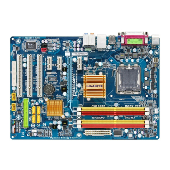
Page 7: Ga-Ep41-Ud3L/Us3L Motherboard Layout
GA-EP41-UD3L/ PCIEX1_1 GA-EP41-US3L PCIEX16 RTL8111C/D(L) PCIEX1_2 CLR_CMOS Intel ® ICH7 CODEC PCIEX1_3 SPDIF_O BATTERY CD_IN PCI1 SATA2_0 SATA2_2 SYS_FAN2 SPDIF_I PCI2 SATA2_1 SATA2_3 PCI3 B_BIOS M_BIOS PWR_LED F_USB1 F_USB2 F_PANEL «*» The GA-EP41-UD3L adopts All-Solid Capacitor design. — 7 -…
-
Page 8: Block Diagram
Block Diagram PCIe CLK CPU CLK+/- (100 MHz) LGA775 (333/266/200 MHz) Processor 1 PCI Express x16 Host Interface DDR2 800/667 MHz PCI Express x16 Dual Channel Memory ® Intel GMCH CLK (333/266/200 MHz) RJ45 RTL8111C/D(L) Dual BIOS ATA-100/66/33 PCI Express Bus IDE Channel 3 PCI Express x1 4 SATA 3Gb/s…
-
Page 9: Chapter 1 Hardware Installation
Chapter 1 Hardware Installation Installation Precautions The motherboard contains numerous delicate electronic circuits and components which can become damaged as a result of electrostatic discharge (ESD). Prior to installation, carefully read the user’s manual and follow these procedures: • Prior to installation, do not remove or break motherboard S/N (Serial Number) sticker or warranty sticker provided by your dealer.
-
Page 10: Product Specifications
Pentium processor/Intel Celeron processor in the LGA775 package ® ® ® ® (Go to GIGABYTE’s website for the latest CPU support list.) L2 cache varies with CPU Front Side Bus 1333/1066/800 MHz FSB Chipset North Bridge: Intel G41 Express Chipset ®…
-
Page 11
Internal Connectors 1 x 24-pin ATX main power connector 1 x 4-pin ATX 12V power connector 1 x floppy disk drive connector 1 x IDE connector 4 x SATA 3Gb/s connectors 1 x CPU fan header … -
Page 12
DDR2_1 or DDR2_3 socket; to install two memory modules, we suggest that you install them on the DDR2_1 and DDR2_3 sockets. (Go to GIGABYTE’s website for the latest memory support list.) (Note 3) Whether the CPU/system fan speed control function is supported will depend on the CPU/system cooler you install. -
Page 13: Installing The Cpu And Cpu Cooler
Read the following guidelines before you begin to install the CPU: • Make sure that the motherboard supports the CPU. (Go to GIGABYTE’s website for the latest CPU support list.) • Always turn off the computer and unplug the power cord from the power outlet before installing the CPU to prevent hardware damage.
-
Page 14
B. Follow the steps below to correctly install the CPU into the motherboard CPU socket. Before installing the CPU, make sure to turn off the computer and unplug the power cord from the power outlet to prevent damage to the CPU. CPU Socket Lever Step 1: Step 2:… -
Page 15: Installing The Cpu Cooler
1-3-2 Installing the CPU Cooler Follow the steps below to correctly install the CPU cooler on the motherboard. (The following procedure uses Intel boxed cooler as the example cooler.) ® Male Push Direction of the Arrow Sign on the Male Push The Top of Female Push Pin…
-
Page 16: Installing The Memory
DDR2_1 or DDR2_3 socket; to install two memory modules, we suggest that you install them on the DDR2_1 and DDR2_3 sockets. (Go to GIGABYTE’s website for the latest memory support list.) When memory modules of different capacity and chips are installed, a message which says mem- ory is operating in Flex Memory Mode will appear during the POST.
-
Page 17: Installing A Memory
1-4-2 Installing a Memory Before installing a memory module, make sure to turn off the computer and unplug the power cord from the power outlet to prevent damage to the memory module. DDR2 DIMMs are not compatible to DDR DIMMs. Be sure to install DDR2 DIMMs on this moth- erboard.
-
Page 18: Installing An Expansion Card
Installing an Expansion Card Read the following guidelines before you begin to install an expansion card: • Make sure the motherboard supports the expansion card. Carefully read the manual that came with your expansion card. • Always turn off the computer and unplug the power cord from the power outlet before installing an expansion card to prevent hardware damage.
-
Page 19: Back Panel Connectors
Back Panel Connectors PS/2 Keyboard and PS/2 Mouse Port Use the upper port (green) to connect a PS/2 mouse and the lower port (purple) to connect a PS/2 keyboard. Parallel Port Use the parallel port to connect devices such as a printer, scanner and etc. The parallel port is also called a printer port.
-
Page 20
Center/Subwoofer Speaker Out Jack (Orange) Use this audio jack to connect center/subwoofer speakers in a 5.1/7.1-channel audio configuration. Rear Speaker Out Jack (Black) Use this audio jack to connect rear speakers in a 4/5.1/7.1-channel audio configuration. Side Speaker Out Jack (Gray) Use this audio jack to connect side speakers in a 7.1-channel audio configuration. -
Page 21: Internal Connectors
Internal Connectors 3 19 ATX_12V F_PANEL F_AUDIO CPU_FAN CD_IN SYS_FAN1/2 SPDIF_I PWR_FAN SPDIF_O F_USB1/F_USB2 SATA2_0/1/2/3 CLR_CMOS PWR_LED PHASE_LED BATTERY Read the following guidelines before connecting external devices: • First make sure your devices are compliant with the connectors you wish to connect. • Before installing the devices, be sure to turn off the devices and your computer.
-
Page 22
1/2) ATX_12V/ATX (2×2 12V Power Connector and 2×12 Main Power Connector) With the use of the power connector, the power supply can supply enough stable power to all the components on the motherboard. Before connecting the power connector, first make sure the power supply is turned off and all devices are properly installed. -
Page 23
3/4/5) CPU_FAN/SYS_FAN1/SYS_FAN2/PWR_FAN (Fan Headers) The motherboard has a 4-pin CPU fan header (CPU_FAN), a 4-pin (SYS_FAN2) and a 3-pin (SYS_FAN1) system fan headers, and a 3-pin power fan header (PWR_FAN). Most fan headers possess a foolproof insertion design. When connecting a fan cable, be sure to connect it in the correct orientation (the black connector wire is the ground wire). -
Page 24
7) IDE (IDE Connector) The IDE connector supports up to two IDE devices such as hard drives and optical drives. Before attach- ing the IDE cable, locate the foolproof groove on the connector. If you wish to connect two IDE devices, remember to set the jumpers and the cabling according to the role of the IDE devices (for example, master or slave). -
Page 25: System Power Led Header
9) PWR_LED (System Power LED Header) This header can be used to connect a system power LED on the chassis to indicate system power status. The LED is on when the system is operating. The LED keeps blinking when the system is in S1 sleep state.
-
Page 26: F_Panel
11) F_PANEL (Front Panel Header) Connect the power switch, reset switch, speaker and system status indicator on the chassis front panel to this header according to the pin assignments below. Note the positive and negative pins before con- necting the cables. Message/Power/ Power Speaker…
-
Page 27: Cd In Connector
12) F_AUDIO (Front Panel Audio Header) The front panel audio header supports Intel High Definition audio (HD) and AC’97 audio. You may connect your chassis front panel audio module to this header. Make sure the wire assignments of the module con- nector match the pin assignments of the motherboard header.
-
Page 28
14) SPDIF_I (S/PDIF In Header, Red) This header supports digital S/PDIF In and can connect to an audio device that supports digital audio out via an optional S/PDIF In cable. For purchasing the optional S/PDIF In cable, please contact the local dealer. -
Page 29
16) F_USB1/F_USB2 (USB Headers) The headers conform to USB 2.0/1.1 specification. Each USB header can provide two USB ports via an optional USB bracket. For purchasing the optional USB bracket, please contact the local dealer. Pin No. Definition Power (5V) Power (5V) USB DX- USB DY-… -
Page 30: Clear Cmos Jumper
18) CLR_CMOS (Clearing CMOS Jumper) Use this jumper to clear the CMOS values (e.g. date information and BIOS configurations) and reset the CMOS values to factory defaults. To clear the CMOS values, place a jumper cap on the two pins to temporarily short the two pins or use a metal object like a screwdriver to touch the two pins for a few seconds.
-
Page 31: Chapter 2 Bios Setup
To see more advanced BIOS Setup menu options, you can press <Ctrl> + <F1> in the main menu of the BIOS Setup program. To upgrade the BIOS, use either the GIGABYTE Q-Flash or @BIOS utility. Q-Flash allows the user to quickly and easily upgrade or back up BIOS without entering the operating •…
-
Page 32: Startup Screen
Startup Screen The following screens may appear when the computer boots. A. The LOGO Screen (Default) Function Keys B. The POST Screen Award Modular BIOS v6.00PG, An Energy Star Ally Copyright (C) 1984-2009, Award Software, Inc. EP41-UD3L F2e Motherboard Model BIOS Version Function Keys <DEL>: BIOS Setup <F9>: XpressRecovery2 <F12>: Boot Menu <End>: Qflash…
-
Page 33: The Main Menu
Once you enter the BIOS Setup program, the Main Menu (as shown below) appears on the screen. Use ar- row keys to move among the items and press <Enter> to accept or enter a sub-menu. (Sample BIOS Version: GA-EP41-UD3L F2e) CMOS Setup Utility-Copyright (C) 1984-2009 Award Software MB Intelligent Tweaker(M.I.T.)
-
Page 34: Standard Cmos Features
The Functions of the <F11> and <F12> keys (For the Main Menu Only) F11: Save CMOS to BIOS This function allows you to save the current BIOS settings to a profile. You can create up to 8 profiles (Profile 1-8) and name each profile.
-
Page 35: Mb Intelligent Tweaker(M.i.t.)
MB Intelligent Tweaker(M.I.T.) CMOS Setup Utility-Copyright (C) 1984-2009 Award Software MB Intelligent Tweaker(M.I.T.) Item Help Robust Graphics Booster [Auto] Menu Level CPU Clock Ratio [10X] (Note) Fine CPU Clock Ratio [+0.0] (Note) CPU Frequency 2.66GHz ( 266×10) ******** Clock Chip Control ******** >>>>>…
-
Page 36: Cpu Frequency
Robust Graphics Booster Robust Graphics Booster (R.G.B.) helps to enhance the performance of the graphics chip and memory. Auto allows the BIOS to automatically set the R.G.B. mode based on system configurations. Options are: Auto (default), Fast, Turbo. CPU Clock Ratio (Note) Allows you to alter the clock ratio for the installed CPU.
-
Page 37
(G)MCH Frequency Latch Allows you to fix the chipset frequency at system bootup. Options for adjusting memory multiplier below may differ according to the fixed frequency. Options are: Auto (default), 200MHz, 266MHz, 333MHz. System Memory Multiplier (SPD) Allows you to set the system memory multiplier. Options are dependent on CPU FSB and the (G)MCH Frequency Latch settings. -
Page 38
>>>>> Advanced Timing Control tRRD Options are: Auto (default), 1~15. tWTR Options are: Auto (default), 1~31. Options are: Auto (default), 1~31. tRFC Options are: Auto (default), 1~255. tRTP Options are: Auto (default), 1~15. Command Rate(CMD) Options are: Auto (default), 1~3. >>>>>… -
Page 39
Trd2rd(Different Rank) Options are: Auto (default), 1~15. Twr2wr(Different Rank) Options are: Auto (default), 1~15. Twr2rd(Different Rank) Options are: Auto (default), 1~15. Trd2wr(Same/Diff Rank) Options are: Auto (default), 1~15. DIMM1 Clock Skew Control Options are: Auto (default), +800ps~-700ps. DIMM2 Clock Skew Control Options are: Auto (default), +800ps~-700ps. -
Page 40
Clk Driving Pull-Up Level Options are: Auto (default), +8~-7. Data Driving Pull-Down Level Options are: Auto (default), +8~-7. Cmd Driving Pull-Down Level Options are: Auto (default), +8~-7. Ctrl Driving Pull-Down Level Options are: Auto (default), +8~-7. Clk Driving Pull-Down Level Options are: Auto (default), +8~-7. -
Page 41: Standard Cmos Features
Standard CMOS Features CMOS Setup Utility-Copyright (C) 1984-2009 Award Software Standard CMOS Features Item Help Date (mm:dd:yy) Tue, Jan 20 2009 Menu Level Time (hh:mm:ss) 22:31:24 IDE Channel 0 Master [None] IDE Channel 0 Slave [None] IDE Channel 2 Master [None] …
-
Page 42
The following fields display your hard drive specifications. If you wish to enter the parameters manually, refer to the information on the hard drive. Capacity Approximate capacity of the currently installed hard drive. Cylinder Number of cylinders. Head Number of heads. Precomp Write precompensation cylinder. -
Page 43: Advanced Bios Features
Advanced BIOS Features CMOS Setup Utility-Copyright (C) 1984-2009 Award Software Advanced BIOS Features Item Help Hard Disk Boot Priority [Press Enter] Menu Level First Boot Device [Floppy] Second Boot Device [Hard Disk] Third Boot Device [CDROM] Password Check [Setup] HDD S.M.A.R.T.
-
Page 44
CPU Multi-Threading (Note) Allows you to determine whether to enable all CPU cores and multi-threading function when using an Intel CPU that supports multi-core technology. This feature only works for operating systems that support multi-processor mode. Enabled Enables all CPU cores and multi-threading capability. (Default) Disabled Enables only one CPU core. -
Page 45: Init Display First
Full Screen LOGO Show Allows you to determine whether to display the GIGABYTE Logo at system startup. Disabled displays normal POST message. (Default: Enabled) Init Display First Specifies the first initiation of the monitor display from the installed PCI graphics card or the PCI Express graphics card.
-
Page 46: Integrated Peripherals
Integrated Peripherals CMOS Setup Utility-Copyright (C) 1984-2009 Award Software Integrated Peripherals Item Help On-Chip Primary PCI IDE [Enabled] Menu Level On-Chip SATA Mode [Auto] x PATA IDE Set to Ch.0 Master/Slave SATA Port 0/2 Set to Ch.2 Master/Slave SATA Port 1/3 Set to Ch.3 Master/Slave Azalia Codec [Auto]…
-
Page 47
SATA Port 1/3 Set to This value is dependent on the On-Chip SATA Mode and PATA IDE Set to settings. When PATA IDE Set to is configured to Ch. 0 Master/Slave, this option will be automatically set to Ch. 1 Master/Slave. -
Page 48: Onboard Parallel Port
When a Cable Problem Occurs… If a cable problem occurs on a specified pair of wires, the Status field will show Short and then length shown will be the approximate distance to the fault or short. Example: Part1-2 Status = Short / Length Explanation: A fault or short might occur at about 2m on Part 1-2.
-
Page 49: Power Management Setup
Power Management Setup CMOS Setup Utility-Copyright (C) 1984-2009 Award Software Power Management Setup Item Help ACPI Suspend Type [S3(STR)] Menu Level Soft-Off by PWR-BTTN [Instant-Off] PME Event Wake Up [Enabled] Power On by Ring [Enabled] Resume by Alarm [Disabled] Date (of Month) Alarm Everyday Time (hh:mm:ss) Alarm…
-
Page 50
Resume by Alarm Determines whether to power on the system at a desired time. (Default: Disabled) If enabled, set the date and time as following: Date (of Month) Alarm: Turn on the system at a specific time on each day or on a specific day in a month. -
Page 51: Pnp/Pci Configurations
PnP/PCI Configurations CMOS Setup Utility-Copyright (C) 1984-2009 Award Software PnP/PCI Configurations Item Help PCI1 IRQ Assignment [Auto] Menu Level PCI2 IRQ Assignment [Auto] PCI3 IRQ Assignment [Auto] higf : Move Enter: Select +/-/PU/PD: Value F10: Save ESC: Exit F1: General Help F5: Previous Values F6: Fail-Safe Defaults F7: Optimized Defaults…
-
Page 52: Pc Health Status
PC Health Status CMOS Setup Utility-Copyright (C) 1984-2009 Award Software PC Health Status Item Help Reset Case Open Status [Disabled] Menu Level Case Opened Vcore 1.140V DDR18V 1.840V +3.3V 3.328V +12V 12.048V Current System Temperature Current CPU Temperature Current CPU FAN Speed 2872 RPM Current SYSTEM FAN2 Speed Current POWER FAN Speed…
-
Page 53: Load Fail-Safe Defaults
2-10 Load Fail-Safe Defaults CMOS Setup Utility-Copyright (C) 1984-2009 Award Software MB Intelligent Tweaker(M.I.T.) Load Fail-Safe Defaults Standard CMOS Features Load Optimized Defaults Advanced BIOS Features Set Supervisor Password Integrated Peripherals Set User Password Power Management Setup Save &…
-
Page 54: Set Supervisor/User Password
2-12 Set Supervisor/User Password CMOS Setup Utility-Copyright (C) 1984-2009 Award Software MB Intelligent Tweaker(M.I.T.) Load Fail-Safe Defaults Standard CMOS Features Load Optimized Defaults Advanced BIOS Features Set Supervisor Password Integrated Peripherals Set User Password Power Management Setup Save &…
-
Page 55: Save & Exit Setup
2-13 Save & Exit Setup CMOS Setup Utility-Copyright (C) 1984-2009 Award Software MB Intelligent Tweaker(M.I.T.) Load Fail-Safe Defaults Standard CMOS Features Load Optimized Defaults Advanced BIOS Features Set Supervisor Password Save to CMOS and EXIT (Y/N)? Y Integrated Peripherals Set User Password …
-
Page 56
BIOS Setup — 56 -… -
Page 57: Chapter 3 Drivers Installation
Chapter 3 Drivers Installation • Before installing the drivers, first install the operating system. • After installing the operating system, insert the motherboard driver disk into your optical drive. The driver Autorun screen is automatically displayed which looks like that shown in the screen shot below.
-
Page 58: Application Software
Application Software This page displays all the utilities and applications that GIGABYTE develops and some free software. You can click the Install button on the right of an item to install it. Technical Manuals This page provides GIGABYTE’s application guides, content descriptions for this driver disk, and the mother- board manuals.
-
Page 59: Contact
Contact For the detailed contact information of the GIGABYTE Taiwan headquarter or worldwide branch offices, click the URL on this page to link to the GIGABYTE website. System This page provides the basic system information. — 59 — Drivers Installation…
-
Page 60: Download Center
Download Center To update the BIOS, drivers, or applications, click the Download Center button to link to the GIGABYTE website. The latest version of the BIOS, drivers, or applications will be displayed. Drivers Installation — 60 -…
-
Page 61: Chapter 4 Unique Features
Chapter 4 Unique Features Xpress Recovery2 Xpress Recovery2 is a utility that allows you to quickly compress and back up your system data and perform restoration of it. Supporting NTFS, FAT32, and FAT16 file systems, Xpress Recovery2 can back up data on PATA and SATA hard drives and restore it.
-
Page 62
Step 3: Step 4: When partitioning your hard drive, make sure to After the operating system is installed, right-click the Computer icon on your desktop and select leave unallocated space (10 GB or more is recom- mended; actual size requirements vary, depending Manage. -
Page 63
D. Using the Restore Function in Xpress Recovery2 Select RESTORE to restore the backup to your hard drive in case the system breaks down. The RESTORE option will not be present if no backup is created before. E. Removing the Backup Step 1: Step 2: If you wish to remove the backup file, select… -
Page 64: Bios Update Utilities
4-2-1 Updating the BIOS with the Q-Flash Utility A. Before You Begin From GIGABYTE’s website, download the latest compressed BIOS update file that matches your moth- erboard model. Extract the file and save the new BIOS file (e.g. EP41UD3L.F1) to your floppy disk, USB flash drive, or hard drive.
-
Page 65
B. Updating the BIOS When updating the BIOS, choose the location where the BIOS file is saved. The following procedure as- sumes that you save the BIOS file to a floppy disk. Step 1: Insert the floppy disk containing the BIOS file into the floppy disk drive. In the main menu of Q-Flash, use the up or down arrow key to select Update BIOS from Drive and press <Enter>. -
Page 66
Step 4: Press <Esc> and then <Enter> to exit Q-Flash and reboot the system. As the system boots, you should see the new BIOS version is present on the POST screen. Step 5: During the POST, press <Delete> to enter BIOS Setup. Select Load Optimized Defaults and press <Enter> to load BIOS defaults. -
Page 67: Updating The Bios With The @Bios Utility
BIOS or a system that is unable to start. Do not use the G.O.M. (GIGABYTE Online Management) function when using @BIOS. GIGABYTE product warranty does not cover any BIOS damage or system failure resulting from an inad- equate BIOS flashing.
-
Page 68: Easytune 6
EasyTune 6 GIGABYTE’s EasyTune 6 is a simple and easy-to-use interface that allows users to fine-tune their system settings or do overclock/overvoltage in Windows environment. The user-friendly EasyTune 6 interface also includes tabbed pages for CPU and memory information, letting users read their system-related information without the need to install additional software.
-
Page 69: Dynamic Energy Saver Advanced
The Dynamic Energy Saver Advanced Interface A. Meter Mode In Meter Mode, GIGABYTE Dynamic Energy Saver Advanced shows how much power they have saved in a set period of time. Meter Mode — Button Information Table…
-
Page 70
B. Total Mode In Total Mode, users are able to see how much total power savings they have accumulated in a set period of time since activating Dynamic Energy Saver Advanced for the first time (Note 4) Total Mode — Button Information Table Button Description Dynamic Energy Saver On/Off Switch (Default: Off) Motherboard Phase LED On/Off Switch (Default: On) -
Page 71: Q-Share
Q-Share, you are able to share your data with computers on the same network, making full use of Internet resources. Directions for using Q-Share After installing Q-Share from the motherboard driver disk, go to Start>All Programs>GIGABYTE>Q-Share.exe to launch the Q-Share tool. Find the Q-Share icon in your taskbar and right-click on this icon to configure the data sharing settings.
-
Page 72: Time Repair
Time Repair Based on the Microsoft Volume Shadow Copy Services technology, Time Repair allows you to quickly back up and restore your system data in the Windows Vista operating system. Time Repair supports NTFS file system and can restore system data on PATA and SATA hard drives. System Restore Choose a system restore point using the navigation bar on the right or at the bottom of the screen to view the system data backed up at different time.
-
Page 73: Chapter 5 Appendix
Chapter 5 Appendix Configuring Audio Input and Output 5-1-1 Configuring 2/4/5.1/7.1-Channel Audio The motherboard provides six audio jacks on the back panel which support 2/4/5.1/7.1-channel audio. (Note) The picture to the right shows the default audio jack Center/Subwoofer Line In Speaker Out assignments.
-
Page 74
Step 2: Connect an audio device to an audio jack. The The current connected device is dialog box appears. Select the device according to the type of device you connect. Then click OK. Step 3: On the Speakers screen, click the Speaker Configura- tion tab. -
Page 75: Configuring S/Pdif In/Out
5-1-2 Configuring S/PDIF In/Out A. S/PDIF In The S/PDIF In cable (optional) allows you to input digital audio signals to the computer for audio processing. S/PDIF In Cable Optical Coaxial S/PDIF In S/PDIF In 1. Installing the S/PDIF In Cable: Step 1: Step 2: First, attach the connector at the end of the cable…
-
Page 76
B. S/PDIF Out The S/PDIF Out jacks can transmit audio signals to an external decoder for decoding to get the best audio quality. 1. Connecting a S/PDIF Out Cable: S/PDIF Coaxial Cable S/PDIF Optical Cable Connect a S/PDIF coaxial cable or a S/PDIF optical cable (either one) to an external decoder for transmitting the S/PDIF digital audio signals. -
Page 77: Configuring Microphone Recording
5-1-3 Configuring Microphone Recording Step 1: After installing the audio driver, the HD Audio Manager icon will appear in the notification area. Double-click the icon to access the HD Audio Manager. Step 2: Connect your microphone to the Mic in jack (pink) on the back panel or the Mic in jack (pink) on the front panel.
-
Page 78
Step 4: To raise the recording and playback volume for the microphone, click the Microphone Boost icon the right of the Recording Volume slider and set the Microphone Boost level. Step 5: After completing the settings above, click Start, point to All Programs, point to Accessories, and then click Sound Recorder to begin the sound recording. -
Page 79: Using The Sound Recorder
Step 3: When the Stereo Mix item appears, right-click on this item and select Enable. Then set it as the default device. Step 4: Now you can access the HD Audio Manager to config- ure Stereo Mix and use Sound Recorder to record the sound.
-
Page 80: Troubleshooting
5-2-1 Frequently Asked Questions To read more FAQs for your motherboard, please go to the Support&DownloadsMotherboardFAQ page on GIGABYTE’s website. Q: In the BIOS Setup program, why are some BIOS options missing? A: Some advanced options are hidden in the BIOS Setup program. Press <Delete> to enter BIOS Setup dur- ing the POST.
-
Page 81: Troubleshooting Procedure
5-2-2 Troubleshooting Procedure If you encounter any troubles during system startup, follow the troubleshooting procedure below to solve the problem. START Turn off the power. Remove all peripherals, connecting cables, and power cord etc. Make sure the motherboard does not short-circuit with the chassis or Isolate the short circuit.
-
Page 82
The power supply, CPU or When the computer is turned on, is the CPU cooler running? CPU socket might fail. The problem is verified and solved. The graphics card, expansion slot, or monitor Check if there is display on your monitor. might fail. -
Page 83: Regulatory Statements
Contravention will be prosecuted. We believe that the information contained herein was accurate in all respects at the time of printing. GIGABYTE cannot, however, assume any responsibility for errors or omissions in this text. Also note that the informa- tion in this document is subject to change without notice and should not be construed as a commitment by GIGABYTE.
-
Page 84
Finally, we suggest that you practice other environmentally friendly actions by understanding and using the energy-saving features of this product (where applicable), recycling the inner and outer packaging (including shipping containers) this product was delivered in, and by disposing of or recycling used batteries properly. With your help, we can reduce the amount of natural resources needed to produce electrical and electronic equipment, minimize the use of landfills for the disposal of «end of life»… -
Page 85
— 85 — Appendix… -
Page 86
Appendix — 86 -… -
Page 87
Shenyang http://rma.gigabyte-usa.com Web address: http://latam.giga-byte.com TEL: +86-24-83992901 • Giga-Byte SINGAPORE PTE. LTD. — Singapore FAX: +86-24-83992909 • GIGABYTE TECHNOLOGY (INDIA) LIMITED — India WEB address : http://www.gigabyte.sg • Thailand WEB address : http://www.gigabyte.in WEB address : http://th.giga-byte.com • Saudi Arabia •… -
Page 88
WEB address : http://www.giga-byte.gr WEB address : http://www.giga-byte.kz • Czech Republic You may go to the GIGABYTE website, select your language WEB address : http://www.gigabyte.cz in the language list on the top right corner of the website. • GIGABYTE Global Service System…
Specifications:
|
Accompanying Data:
Gigabyte GA-EP41-UD3L Motherboard PDF Operation & User’s Manual (Updated: Sunday 19th of February 2023 11:09:45 AM)
Rating: 4.7 (rated by 46 users)
Compatible devices: GA-8PE800, GA-8SG667, GA-EP43-DS3, XP-M8VM800, GA-8IDX3, GA-8I915ME Series, GA-8I915G Pro, GA-8I915G Duo.
Recommended Documentation:
Gigabyte GA-EP41-UD3L: Text of Operation & User’s Manual
(Ocr-Read Version Summary of Contents, UPD: 19 February 2023)
-
80, Appendix — 80 — 5-2 Troubleshooting 5-2-1 Frequently Asked Questions To read more FAQs for your motherboard, please go to the Support&DownloadsMotherboardFAQ page on GIGABYTE’s website. Q: In the BIOS Setup program, why are some BIOS options missing? A: Some advanced options are hidden in the BIOS Setup program. Press <Delete> to enter BIOS Setu…
-
73, — 73 — Appendix 5-1-1 Conguring 2/4/5.1/7.1-Channel Audio The motherboard provides six audio jacks on the back panel which support 2/4/5.1/7.1-channel (Note) audio. The picture to the right shows the default audio jack assignments. The integrated HD (High Definition) audio provides jack retasking capability that allows the user to change the function f…
-
44, BIOS Setup — 44 — CPU Multi-Threading (Note) Allows you to determine whether to enable all CPU cores and multi-threading function when using an Intel CPU that supports multi-core technology. This feature only works for operating systems that support multi-processor mode. Enabled Enables all CPU cores and multi-threading capability. (Default) Disabled Enables only one CPU core. …
-
69, — 69 — Unique Features 4-4 Dynamic Energy Saver Advanced GIGABYTE Dynamic Energy Saver Advanced (Note 1) is a revolutionary technology that delivers unparalleled power savings with a click of the button. Featuring an advanced proprietary hardware and software design, GIGABYTE Dynamic Energy Saver Advanced is able to provide exceptional power savings and enhanced …
-
79, — 79 — Appendix Step 3: When the Stereo Mix item appears, right-click on this item and select Enable. Then set it as the default device. Step 4: Now you can access the HD Audio Manager to cong- ure Stereo Mix and use Sound Recorder to record the sound. 5-1-4 Using the Sound Recorder A. Recording Sound 1. Make sure you have connected the sound input…
-
88, Appendix — 88 — • G.B.T. TECHNOLOGY TRADING GMBH — Germany WEB address : http://www.gigabyte.de • G.B.T. TECH. CO., LTD. — U.K. WEB address : http://www.giga-byte.co.uk • Giga-Byte Technology B.V. — The Netherlands WEB address : http://www.giga-byte.nl • GIGABYTE TECHNOLOGY FRANCE — France WEB address : http://www.gigabyte.fr • Sweden WEB address : http…
-
74, Appendix — 74 — Step 2: Connect an audio device to an audio jack. The The current connected device is dialog box appears. Select the device according to the type of device you connect. Then click OK. Step 3: On the Speakers screen, click the Speaker Congura- tion tab. In the Speaker Conguration list, select Stereo, Quadraphonic, 5.1 Sp…
-
4, — 4 — Table of Contents Box Contents …………………………………………………………………………………………………….6 Optional Items …………………………………………………………………………………………………..6 GA-EP41-UD3L/US3L Motherboard Layout ………………………………………….…
-
30, Hardware Installation — 30 — 19) PHASE LED The number of lighted LEDs indicates the CPU loading. The higher the CPU loading, the more the number of lighted LEDs. To enable the Phase LED display function, please rst enable Dynamic Energy Saver Advanced. Refer to Chapter 4, «Dynamic Energy Saver Advanced,» for more details. 18) CLR_C…
-
34, BIOS Setup — 34 — The Functions of the <F11> and <F12> keys (For the Main Menu Only) F11: Save CMOS to BIOS This function allows you to save the current BIOS settings to a prole. You can create up to 8 proles (Prole 1-8) and name each prole. First enter the prole name (to erase the default prole name, use the SPACE key) and …
-
46, BIOS Setup — 46 — 2-6 Integrated Peripherals CMOS Setup Utility-Copyright (C) 1984-2009 Award Software Integrated Peripherals On-Chip Primary PCI IDE [Enabled] On-Chip SATA Mode [Auto] x PATA IDE Set to Ch.0 Master/Slave SATA Port 0/2 Set to Ch.2 Master/Slave SATA Port 1/3 Set to Ch.3 Master/Slave Azalia Codec [Auto] Onboard H/W LA…
-
16, Hardware Installation — 16 — 1-4-1 Dual Channel Memory Conguration This motherboard provides four DDR2 memory sockets and supports Dual Channel Tech- nology. After the memory is installed, the BIOS will automatically detect the specications and capacity of the memory. Enabling Dual Channel memory mode will double the original memory bandwidth. The four DDR2 memory sockets are divided int…
Gigabyte GA-EP41-UD3L: Recommended Instructions
WM1-M, MCD-100, Inno Spot Elite, MultiSync 3090WQXI


-
ASUS M3N78 PRO 5-9Audio congurationsThe Realtek® audio CODEC provides 8-channel audio capability to deliver the ultimate audio experience on your computer. The software provides Jack-Sensing function, S/PDIF Out support, and interrupt capability. The CODEC also includes the Realtek® proprietary UAJ® (Universal Audio Jack) technology for all audio ports, eliminating cable connection …
Application 8
-
EVAL-AD7492SDZ User Guide UG-371 One Technology Way • P. O. Box 9106 • Norwood, MA 02062-9106, U.S.A. • Tel: 781.329.4700 • Fax: 781.461.3113 • www.analog.com Evaluation Board for the AD7492 1.25 MSPS, 16 mW Internal REF and CLK, 12-Bit Parallel ADC PLEASE SEE THE LAST PAGE FOR AN IMPORTANT WARNING AND LEGAL TERMS AND CONDITIONS. Rev. 0 | Page 1 of 24 FEATURES Full-featured evalu …
EVAL-AD7492SDZ 24
-
1This document describes how to replace the dual in-line memory modules (DIMMs, or memory cards) on an AX100-Series motherboard. Topics include◆ Handling FRUs …………………………………………………………………………..2◆ Removing the Storage Processor Assembly ………………………………..4◆ Replacing the Memory Card.. …
AX100 Series 14
-
P4TPT BIOS Setup i BIOS Setup ……………………………………………………………………………1 1 Main Menu ……………………………………………………………………………………… 3 2 Standard CMOS Features ………………………………………………………………….. 6 3 Advanced BIOS Features . …
P4TPT 29
-
Case Open Connector CD-IN ConnectorFront Audio ConnectorIrDA ConnectorFront Panel ConnectorFDD ConnectorUSB2.0 ConnectorJP14 CMOS Clear JumperResetable Fuse478-pin CPU socket (Willamette/Northwood)that supports Intel® Pentium® 4 CPU AGP 4x Expansion Slot 32-bit PCI Expansion Slot x3184-pin DIMMx2 supports DDR200/266 (MX46U2-GN) maximum up to 2 …
MX46U2-GN 8
-
Coaxlink1629 Coaxlink Duo PCIe/104-EMB3300 HD26F I/O module for Coaxlink Duo PCIe/1043301 Thermal drain (Model 1) for Coaxlink Duo PCIe/1043302 DIN1.0/2.3 Coaxial cable for Coaxlink Duo PCIe/104INSTALLATION GUIDE© EURESYS s.a.2018 — Document D221EN-PCIe104 Installation Guide-Coaxlink-10.3.1.2052 built on 2018-11-22 …
Coaxlink Duo PCIe/104-EMB 4
-
ATtiny817 Xplained Pro ATtiny817 Xplained ProPrefaceThe ATtiny817 Xplained Pro evaluation kit is a hardware platform to evaluate the ATtiny817microcontroller.Supported by the Atmel Studio integrated development platform, the kit provides easy access to thefeatures of the ATtiny817 and explains how to integrate the device into a custom design.Xplained Pro MCU se …
ATtiny817 Xplained Pro 35
-
User’s GuideSLAU625–November 2015ADC14X250EVM Evaluation ModuleThis user’s guide describes the characteristics, operation, and use of the ADC14X250EVM EvaluationModule (EVM). This document includes a quick-start guide, directions for optimizing evaluation results, adescription of the software, alternate hardware configurations, and jumper, connector, and LEDd …
ADC14X250EVM 19
Additional Information:
Popular Right Now:
Operating Impressions, Questions and Answers:
View a manual of the Gigabyte GA-EP41-UD3L below. All manuals on ManualsCat.com can be viewed completely free of charge. By using the ‘Select a language’ button, you can choose the language of the manual you want to view.
Page: 1
GA-EP41-UD3L
GA-EP41-US3L
LGA775 socket motherboard for Intel®
Core™
processor family/
Intel®
Pentium®
processor family/Intel®
Celeron®
processor family
User’s Manual
Rev. 1201
12ME-EP41U3L-1201R
Page: 2
Motherboard
GA-EP41-UD3L/
GA-EP41-US3L
Mar.
26,
2009
Mar.
26,
2009
Motherboard
GA-EP41-UD3L/GA-EP41-US3L
Page: 3
Copyright
© 2009 GIGA-BYTE TECHNOLOGY CO., LTD. All rights reserved.
The trademarks mentioned in this manual are legally registered to their respective owners.
Disclaimer
Information in this manual is protected by copyright laws and is the property of GIGABYTE.
Changes to the specifications and features in this manual may be made by GIGABYTE with-
out prior notice. No part of this manual may be reproduced, copied, translated, transmitted, or
published in any form or by any means without GIGABYTE’s prior written permission.
Documentation Classifications
Inordertoassistintheuseofthisproduct,GIGABYTEprovidesthefollowingtypesofdocumentations:
For quick set-up of the product, read the Quick Installation Guide included with the product.
For detailed product information, carefully read the User’s Manual.
For instructions on how to use GIGABYTE’s unique features, read or download the information
on/from the Support&DownloadsMotherboardTechnology Guide page on our website.
For product-related information, check on our website at:
http://www.gigabyte.com.tw
Identifying Your Motherboard Revision
The revision number on your motherboard looks like this: «REV: X.X.» For example, «REV: 1.0»
means the revision of the motherboard is 1.0. Check your motherboard revision before updating
motherboard BIOS, drivers, or when looking for technical information.
Example:
Page: 4
— 4 —
Table of Contents
Box Contents……………………………………………………………………………………………………..6
Optional Items……………………………………………………………………………………………………6
GA-EP41-UD3L/US3L Motherboard Layout……………………………………………………………7
Block Diagram……………………………………………………………………………………………………8
Chapter 1 Hardware Installation…………………………………………………………………………..9
1-1 Installation Precautions…………………………………………………………………………. 9
1-2 Product Specifications.
………………………………………………………………………… 10
1-3 Installing the CPU and CPU Cooler………………………………………………………. 13
1-3-1 Installing the CPU……………………………………………………………………………………….13
1-3-2 Installing the CPU Cooler…………………………………………………………………………….15
1-4 Installing the Memory………………………………………………………………………….. 16
1-4-1 Dual Channel Memory Configuration…………………………………………………………….16
1-4-2 Installing a Memory ……………………………………………………………………………………17
1-5 Installing an Expansion Card……………………………………………………………….. 18
1-6 Back Panel Connectors.
………………………………………………………………………. 19
1-7 Internal Connectors…………………………………………………………………………….. 21
Chapter 2 BIOS Setup………………………………………………………………………………………31
2-1 Startup Screen…………………………………………………………………………………… 32
2-2 The Main Menu………………………………………………………………………………….. 33
2-3 MB Intelligent Tweaker(M.I.T.).
……………………………………………………………… 35
2-4 Standard CMOS Features.
…………………………………………………………………… 41
2-5 Advanced BIOS Features……………………………………………………………………. 43
2-6 Integrated Peripherals…………………………………………………………………………. 46
2-7 Power Management Setup.
………………………………………………………………….. 49
2-8 PnP/PCI Configurations………………………………………………………………………. 51
2-9 PC Health Status.
……………………………………………………………………………….. 52
2-10 Load Fail-Safe Defaults.
………………………………………………………………………. 53
2-11 Load Optimized Defaults……………………………………………………………………… 53
2-12 Set Supervisor/User Password…………………………………………………………….. 54
2-13 Save & Exit Setup………………………………………………………………………………. 55
2-14 Exit Without Saving…………………………………………………………………………….. 55
Page: 5
— 5 —
Chapter 3 Drivers Installation.
…………………………………………………………………………….57
3-1 Installing Chipset Drivers…………………………………………………………………….. 57
3-2 Application Software…………………………………………………………………………… 58
3-3 Technical Manuals.
……………………………………………………………………………… 58
3-4 Contact……………………………………………………………………………………………… 59
3-5 System……………………………………………………………………………………………… 59
3-6 Download Center……………………………………………………………………………….. 60
Chapter 4 Unique Features.
……………………………………………………………………………….61
4-1 Xpress Recovery2………………………………………………………………………………. 61
4-2 BIOS Update Utilities………………………………………………………………………….. 64
4-2-1 Updating the BIOS with the Q-Flash Utility.
…………………………………………………….64
4-2-2 Updating the BIOS with the @BIOS Utility……………………………………………………..67
4-3 EasyTune 6……………………………………………………………………………………….. 68
4-4 Dynamic Energy Saver Advanced.
………………………………………………………… 69
4-5 Q-Share.
……………………………………………………………………………………………. 71
4-6 Time Repair.
………………………………………………………………………………………. 72
Chapter 5 Appendix………………………………………………………………………………………….73
5-1 Configuring Audio Input and Output………………………………………………………. 73
5-1-1 Configuring 2/4/5.1/7.1-Channel Audio.
………………………………………………………….73
5-1-2 Configuring S/PDIF In/Out……………………………………………………………………………75
5-1-3 Configuring Microphone Recording……………………………………………………………….77
5-1-4 Using the Sound Recorder…………………………………………………………………………..79
5-2 Troubleshooting…………………………………………………………………………………. 80
5-2-1 Frequently Asked Questions .
……………………………………………………………………….80
5-2-2 Troubleshooting Procedure………………………………………………………………………….81
5-3 Regulatory Statements.
……………………………………………………………………….. 83
Page: 6
— 6 —
Box Contents
GA-EP41-UD3L or GA-EP41-US3L motherboard
Motherboard driver disk
User’s Manual
Quick Installation Guide
One IDE cable
Two SATA 3Gb/s cables
I/O Shield
Optional Items
Floppy Disk Drive cable (Part No. 12CF1-1FD001-7*R)
2-port USB 2.0 bracket (Part No. 12CR1-1UB030-5*R)
2-port SATA power cable (Part No. 12CF1-2SERPW-0*R)
S/PDIF In cable (Part No. 12CR1-1SPDIN-0*R)
• The box contents above are for reference only and the actual items shall depend on the product package you obtain.
The box contents are subject to change without notice.
• The motherboard image is for reference only.
Page: 7
— 7 —
GA-EP41-UD3L/US3L Motherboard Layout
KB_MS
Optical
Coaxial
CPU_FAN
PHASE_LED
LGA775
ATX
GA-EP41-UD3L/
GA-EP41-US3L
USB
LAN
CD_IN
F_AUDIO
AUDIO
B_BIOS M_BIOS
PCIEX16
PCIEX1_1
IDE
SPDIF_O
SPDIF_I
CI
DDR2_1
DDR2_2
DDR2_3
DDR2_4
BATTERY
F_PANEL
IT8718
SATA2_0
ATX_12V
Intel®
G41
Intel®
ICH7
PWR_LED
FDD
SATA2_1
PCI1
PCI2
R_USB
CLR_CMOS
COM
CODEC
PWR_FAN
SYS_FAN1
F_USB1 F_USB2
SYS_FAN2
LPT
SATA2_2
SATA2_3
PCIEX1_2
PCIEX1_3
PCI3
RTL8111C/D(L)
«*» The GA-EP41-UD3L adopts All-Solid Capacitor design.
Page: 8
— 8 —
Block Diagram
PS/2 KB/Mouse
8 USB Ports
LGA775
Processor
Host
Interface
Intel®
G41
GMCH CLK
(333/266/200 MHz)
DDR2 800/667 MHz
Intel®
ICH7
3 PCI
PCI Bus
Dual Channel Memory
PCI CLK
(33 MHz)
PCIe CLK
(100 MHz)
PCI Express x16
IT8718
Floppy
LPT Port
CPU CLK+/-
(333/266/200 MHz)
3 PCI Express x1
PCI Express Bus
PCIe CLK
(100 MHz)
x1
x1 x1
x1
4 SATA 3Gb/s
ATA-100/66/33
IDE Channel
1 PCI Express x16
Dual BIOS
COM Port
LAN
RJ45
RTL8111C/D(L)
Center/Subwoofer
Speaker
Out
Line
Out
MIC
Line
In
S/PDIF
In
S/
PDIF
Out
Side
Speaker
Out
Surround
Speaker
Out
CODEC
Page: 9
— 9 — Hardware Installation
1-1 Installation Precautions
The motherboard contains numerous delicate electronic circuits and components which can
become damaged as a result of electrostatic discharge (ESD). Prior to installation, carefully read
the user’s manual and follow these procedures:
• Prior to installation, do not remove or break motherboard S/N (Serial Number) sticker or
warranty sticker provided by your dealer. These stickers are required for warranty validation.
• Always remove the AC power by unplugging the power cord from the power outlet before
installing or removing the motherboard or other hardware components.
• When connecting hardware components to the internal connectors on the motherboard,
make sure they are connected tightly and securely.
• When handling the motherboard, avoid touching any metal leads or connectors.
• It is best to wear an electrostatic discharge (ESD) wrist strap when handling electronic com-
ponents such as a motherboard, CPU or memory. If you do not have an ESD wrist strap,
keep your hands dry and first touch a metal object to eliminate static electricity.
• Prior to installing the motherboard, please have it on top of an antistatic pad or within an
electrostatic shielding container.
• Before unplugging the power supply cable from the motherboard, make sure the power sup-
ply has been turned off.
• Before turning on the power, make sure the power supply voltage has been set according to
the local voltage standard.
• Before using the product, please verify that all cables and power connectors of your hard-
ware components are connected.
• To prevent damage to the motherboard, do not allow screws to come in contact with the
motherboard circuit or its components.
• Make sure there are no leftover screws or metal components placed on the motherboard or
within the computer casing.
• Do not place the computer system on an uneven surface.
• Do not place the computer system in a high-temperature environment.
• Turning on the computer power during the installation process can lead to damage to sys-
tem components as well as physical harm to the user.
• If you are uncertain about any installation steps or have a problem related to the use of the
product, please consult a certified computer technician.
Chapter 1 Hardware Installation
Page: 10
Hardware Installation — 10 —
1-2 Product Specifications
CPU Support for an Intel®
Core™
2 Extreme processor/
Intel®
Core™
2 Quad processor/Intel®
Core™
2 Duo processor/
Intel®
Pentium®
processor/Intel®
Celeron®
processor in the LGA775 package
(Go to GIGABYTE’s website for the latest CPU support list.)
L2 cache varies with CPU
Front Side Bus 1333/1066/800 MHz FSB
Chipset North Bridge: Intel®
G41 Express Chipset
South Bridge: Intel®
ICH7
Memory 4 x 1.8V DDR2 DIMM sockets supporting up to 8 GB of system memory(Note 1)
Dual channel memory architecture(Note 2)
Support for DDR2 800/667 MHz memory modules
(Go to GIGABYTE’s website for the latest memory support list.)
Audio Realtek ALC888 codec
High Definition Audio
2/4/5.1/7.1-channel
Support for S/PDIF In/Out
Support for CD In
LAN RTL8111C/D(L) chip (10/100/1000 Mbit)
Expansion Slots 1 x PCI Express x16 slot, running at x16
3 x PCI Express x1 slots
3 x PCI slots
Storage Interface South Bridge:
— 1 x IDE connector supporting ATA-100/66/33 and up to 2 IDE devices
— 4 x SATA 3Gb/s connectors supporting up to 4 SATA 3Gb/s devices
iTE IT8718 chip:
— 1 x floppy disk drive connector supporting up to 1 floppy disk drive
USB Integrated in the South Bridge
Up to 8 USB 2.0/1.1 ports (4 on the back panel, 4 via the USB brackets
connected to the internal USB headers)
«*» The GA-EP41-UD3L adopts All-Solid Capacitor design.
Page: 11
— 11 — Hardware Installation
Internal Connectors w 1 x 24-pin ATX main power connector
w 1 x 4-pin ATX 12V power connector
w 1 x floppy disk drive connector
w 1 x IDE connector
w 4 x SATA 3Gb/s connectors
w 1 x CPU fan header
w 2 x system fan headers
w 1 x power fan header
w 1 x front panel header
w 1 x front panel audio header
w 1 x CD In connector
w 1 x S/PDIF In header
w 1 x S/PDIF Out header
w 2 x USB 2.0/1.1 headers
w 1 x power LED header
w 1 x chassis intrusion header
w 1 x clearing CMOS jumper
Back Panel w 1 x PS/2 keyboard port
Connectors w 1 x PS/2 mouse port
1 x parallel port
1 x coaxial S/PDIF Out connector
1 x optical S/PDIF Out connector
1 x serial port
w 4 x USB 2.0/1.1 ports
w 1 x RJ-45 port
w 6 x audio jacks (Center/Subwoofer Speaker Out/Rear Speaker Out/
Side Speaker Out/Line In/Line Out/Microphone)
I/O Controller w iTE IT8718 chip
Hardware Monitor w System voltage detection
w CPU/System temperature detection
w CPU/System/Power fan speed detection
w CPU overheating warning
w CPU/System/Power fan fail warning
w CPU/System fan speed control(Note 3)
Page: 12
Hardware Installation — 12 —
BIOS w 2 x 8 Mbit flash
w Use of licensed AWARD BIOS
w Support for DualBIOS™
w PnP 1.0a, DMI 2.0, SM BIOS 2.4, ACPI 1.0b
Unique Features w Support for @BIOS
w Support for Q-Flash
w Support for Xpress BIOS Rescue
w Support for Download Center
w Support for Xpress Install
w Support for Xpress Recovery2
w Support for EasyTune(Note 4)
w Support for Dynamic Energy Saver Advanced
w Support for Time Repair
w Support for Q-Share
Bundled Software w Norton Internet Security (OEM version)
Operating System w Support for Microsoft®
Windows®
7/Vista/XP
Form Factor w ATX Form Factor; 30.5cm x 21.0cm
(Note 1) Due to Windows 32-bit operating system limitation, when more than 4 GB of physical memory is
installed, the actual memory size displayed will be less than 4 GB.
(Note 2) Because of chipset limitations, to avoid the system being unable to start or the memory being incor-
rectly detected, if only one memory module is to be installed, we suggest that you install it on the
DDR2_1 or DDR2_3 socket; to install two memory modules, we suggest that you install them on the
DDR2_1 and DDR2_3 sockets. (Go to GIGABYTE’s website for the latest memory support list.)
(Note 3) Whether the CPU/system fan speed control function is supported will depend on the CPU/system
cooler you install.
(Note 4) Available functions in EasyTune may differ by motherboard model.
Page: 13
— 13 — Hardware Installation
1-3 Installing the CPU and CPU Cooler
Read the following guidelines before you begin to install the CPU:
• Make sure that the motherboard supports the CPU.
(Go to GIGABYTE’s website for the latest CPU support list.)
• Always turn off the computer and unplug the power cord from the power outlet before installing
the CPU to prevent hardware damage.
• Locate the pin one of the CPU. The CPU cannot be inserted if oriented incorrectly. (Or you may
locate the notches on both sides of the CPU and alignment keys on the CPU socket.)
• Apply an even and thin layer of thermal grease on the surface of the CPU.
• Do not turn on the computer if the CPU cooler is not installed, otherwise overheating and dam-
age of the CPU may occur.
• Set the CPU host frequency in accordance with the CPU specifications. It is not recommended
that the system bus frequency be set beyond hardware specifications since it does not meet the
standard requirements for the peripherals. If you wish to set the frequency beyond the standard
specifications, please do so according to your hardware specifications including the CPU, graph-
ics card, memory, hard drive, etc.
1-3-1 Installing the CPU
A. Locate the alignment keys on the motherboard CPU socket and the notches on the CPU.
Notch Notch
Alignment Key
Alignment Key
LGA775 CPU
LGA775 CPU Socket
Pin One Corner of the CPU Socket
Triangle Pin One Marking on the CPU
Page: 14
Hardware Installation — 14 —
B. Follow the steps below to correctly install the CPU into the motherboard CPU socket.
Before installing the CPU, make sure to turn off the computer and unplug the power cord from
the power outlet to prevent damage to the CPU.
Step 1:
Completely raise the CPU socket lever.
Step 3:
Remove the protective socket cover from the
load plate. (To protect the CPU socket, always
replace the protective socket cover when the
CPU is not installed.)
Step 5:
Once the CPU is properly inserted, replace the
load plate and push the CPU socket lever back
into its locked position.
Step 2:
Lift the metal load plate from the CPU socket.
(DO NOT touch socket contacts.)
Step 4:
Hold the CPU with your thumb and index fingers.
Align the CPU pin one marking (triangle) with the
pin one corner of the CPU socket (or you may
align the CPU notches with the socket alignment
keys) and gently insert the CPU into position.
CPU Socket Lever
Page: 15
— 15 — Hardware Installation
1-3-2 Installing the CPU Cooler
Follow the steps below to correctly install the CPU cooler on the motherboard. (The following procedure uses
Intel®
boxed cooler as the example cooler.)
Step 1:
Apply an even and thin layer of thermal grease
on the surface of the installed CPU.
Male Push
Pin
Female
Push Pin
The Top
of Female
Push Pin
Direction of the
Arrow Sign on
the Male Push
Pin
Step 2:
Before installing the cooler, note the direction of
the arrow sign on the male push pin. (Turn-
ing the push pin along the direction of arrow is to
remove the cooler, on the contrary, is to install.)
Step 3:
Place the cooler atop the CPU, aligning the four
push pins through the pin holes on the mother-
board. Push down on the push pins diagonally.
Step 4:
You should hear a «click» when pushing down
each push pin. Check that the Male and Female
push pins are joined closely. (Refer to your CPU
cooler installation manual for instructions on
installing the cooler.)
Use extreme care when removing the CPU cooler because the thermal grease/tape between the
CPU cooler and CPU may adhere to the CPU. Inadequately removing the CPU cooler may damage
the CPU.
Step 5:
After the installation, check the back of the moth-
erboard. If the push pin is inserted as the picture
above shows, the installation is complete.
Step 6:
Finally, attach the power connector of the CPU
cooler to the CPU fan header (CPU_FAN) on the
motherboard.
Page: 16
Hardware Installation — 16 —
1-4-1 Dual Channel Memory Configuration
This motherboard provides four DDR2 memory sockets and supports Dual Channel Tech-
nology. After the memory is installed, the BIOS will automatically detect the specifications
and capacity of the memory. Enabling Dual Channel memory mode will double the original
memory bandwidth.
The four DDR2 memory sockets are divided into two channels and each channel has two memory sockets as
following:
Channel 0: DDR2_1, DDR2_2
Channel 1: DDR2_3, DDR2_4
1-4 Installing the Memory
DDR2_1
DDR2_2
DDR2_3
DDR2_4
Dual Channel Memory Configurations Table
(SS=Single-Sided, DS=Double-Sided, «- -«=No Memory)
DDR2_1 DDR2_2 DDR2_3 DDR2_4
DS/SS — — DS/SS — —
— — DS/SS — — DS/SS
SS SS SS SS
Two Modules
Four Modules
Due to chipset limitations, read the following guidelines before installing the memory in Dual Channel mode.
1. Dual Channel mode cannot be enabled if only one DDR2 memory module is installed.
2. When enabling Dual Channel mode with two or four memory modules, it is recommended that
memory of the same capacity, brand, speed, and chips be used and installed in the same colored
DDR2 sockets for optimum performance.
3. Because of chipset limitations, to avoid the system being unable to start or the memory being incor-
rectly detected, if only one memory module is to be installed, we suggest that you install it on the
DDR2_1 or DDR2_3 socket; to install two memory modules, we suggest that you install them on the
DDR2_1 and DDR2_3 sockets. (Go to GIGABYTE’s website for the latest memory support list.)
Read the following guidelines before you begin to install the memory:
• Make sure that the motherboard supports the memory. It is recommended that memory of the
same capacity, brand, speed, and chips be used.
(Go to GIGABYTE’s website for the latest memory support list.)
• Always turn off the computer and unplug the power cord from the power outlet before installing
the memory to prevent hardware damage.
• Memory modules have a foolproof design. A memory module can be installed in only one direc-
tion. If you are unable to insert the memory, switch the direction.
When memory modules of different capacity and chips are installed, a message which says mem-
ory is operating in Flex Memory Mode will appear during the POST. Intel Flex Memory Technology
offers greater flexibility to upgrade by allowing different memory sizes to be populated and remain in
Dual Channel mode/performance.
Page: 17
— 17 — Hardware Installation
1-4-2 Installing a Memory
Notch
DDR2 DIMM
A DDR2 memory module has a notch, so it can only fit in one direction. Follow the steps below to correctly
install your memory modules in the memory sockets.
Step 1:
Note the orientation of the memory module. Spread the retaining
clips at both ends of the memory socket. Place the memory module
on the socket. As indicated in the picture on the left, place your fin-
gers on the top edge of the memory, push down on the memory and
insert it vertically into the memory socket.
Step 2:
The clips at both ends of the socket will snap into place when the
memory module is securely inserted.
Before installing a memory module, make sure to turn off the computer and unplug the power
cord from the power outlet to prevent damage to the memory module.
DDR2 DIMMs are not compatible to DDR DIMMs. Be sure to install DDR2 DIMMs on this moth-
erboard.
Page: 18
Hardware Installation — 18 —
PCI Slot
1-5 Installing an Expansion Card
PCI Express x1 Slot
Follow the steps below to correctly install your expansion card in the expansion slot.
1. Locate an expansion slot that supports your card. Remove the metal slot cover from the chassis back panel.
2. Align the card with the slot, and press down on the card until it is fully seated in the slot.
3. Make sure the metal contacts on the card are completely inserted into the slot.
4. Secure the card’s metal bracket to the chassis back panel with a screw.
5. After installing all expansion cards, replace the chassis cover(s).
6. Turn on your computer. If necessary, go to BIOS Setup to make any required BIOS changes for your
expansion card(s).
7. Install the driver provided with the expansion card in your operating system.
Example: Installing and Removing a PCI Express x16 Graphics Card:
• Installing a Graphics Card:
Gently push down on the top edge of the card until
it is fully inserted into the PCI Express x16 slot.
Make sure the card is securely seated in the slot
and does not rock.
• Removing the Card:
Gently push back on the lever on the slot and then lift the card straight out from
the slot.
PCI Express x16 Slot
Read the following guidelines before you begin to install an expansion card:
• Make sure the motherboard supports the expansion card. Carefully read the manual that came
with your expansion card.
• Always turn off the computer and unplug the power cord from the power outlet before installing
an expansion card to prevent hardware damage.
Page: 19
— 19 — Hardware Installation
1-6 Back Panel Connectors
PS/2 Keyboard and PS/2 Mouse Port
Use the upper port (green) to connect a PS/2 mouse and the lower port (purple) to connect a PS/2
keyboard.
Parallel Port
Use the parallel port to connect devices such as a printer, scanner and etc. The parallel port is also
called a printer port.
Coaxial S/PDIF Out Connector
This connector provides digital audio out to an external audio system that supports digital coaxial audio.
Before using this feature, ensure that your audio system provides a coaxial digital audio in connector.
Optical S/PDIF Out Connector
This connector provides digital audio out to an external audio system that supports digital optical audio.
Before using this feature, ensure that your audio system provides an optical digital audio in connector.
Serial Port
Use the serial port to connect devices such as a mouse, modem or other peripherals.
USB Port
The USB port supports the USB 2.0/1.1 specification. Use this port for USB devices such as a USB
keyboard/mouse, USB printer, USB flash drive and etc.
RJ-45 LAN Port
The Gigabit Ethernet LAN port provides Internet connection at up to 1 Gbps data rate. The following
describes the states of the LAN port LEDs.
Activity LED:
State Description
Blinking Data transmission or receiving is occurring
Off No data transmission or receiving is occurring
Connection/Speed LED:
State Description
Orange 1 Gbps data rate
Green 100 Mbps data rate
Off 10 Mbps data rate
Activity LED
Connection/
Speed LED
LAN Port
• When removing the cable connected to a back panel connector, first remove the cable from your
device and then remove it from the motherboard.
• When removing the cable, pull it straight out from the connector. Do not rock it side to side to
prevent an electrical short inside the cable connector.
Page: 20
Hardware Installation — 20 —
Center/Subwoofer Speaker Out Jack (Orange)
Use this audio jack to connect center/subwoofer speakers in a 5.1/7.1-channel audio configuration.
Rear Speaker Out Jack (Black)
Use this audio jack to connect rear speakers in a 4/5.1/7.1-channel audio configuration.
Side Speaker Out Jack (Gray)
Use this audio jack to connect side speakers in a 7.1-channel audio configuration.
Line In Jack (Blue)
The default line in jack. Use this audio jack for line in devices such as an optical drive, walkman, etc.
Line Out Jack (Green)
The default line out jack. Use this audio jack for a headphone or 2-channel speaker. This jack can be
used to connect front speakers in a 4/5.1/7.1-channel audio configuration.
Mic In Jack (Pink)
The default Mic in jack. Microphones must be connected to this jack.
In addition to the default speakers settings, the ~ audio jacks can be reconfigured to
perform different functions via the audio software. Only microphones still MUST be connected to
the default Mic in jack ( ). Refer to the instructions on setting up a 2/4/5.1/7.1-channel audio
configuration in Chapter 5, «Configuring 2/4/5.1/7.1-Channel Audio.»
Page: 21
— 21 — Hardware Installation
1-7 Internal Connectors
1
2
3 19
5
4
11
7
6 16
12
15
4
14
17
18
9
8
10
13
1) ATX_12V
2) ATX
3) CPU_FAN
4) SYS_FAN1/2
5) PWR_FAN
6) FDD
7) IDE
 SATA2_0/1/2/3
9) PWR_LED
10) BATTERY
11) F_PANEL
12) F_AUDIO
13) CD_IN
14) SPDIF_I
15) SPDIF_O
16) F_USB1/F_USB2
17) CI
18) CLR_CMOS
19) PHASE_LED
Read the following guidelines before connecting external devices:
• First make sure your devices are compliant with the connectors you wish to connect.
• Before installing the devices, be sure to turn off the devices and your computer. Unplug the
power cord from the power outlet to prevent damage to the devices.
• After installing the device and before turning on the computer, make sure the device cable has
been securely attached to the connector on the motherboard.
Page: 22
Hardware Installation — 22 —
ATX_12V:
ATX_12V
1
3
2
4
13
1
24
12
ATX
ATX:
Pin No. Definition
13 3.3V
14 -12V
15 GND
16 PS_ON (soft On/Off)
17 GND
18 GND
19 GND
20 -5V
21 +5V
22 +5V
23 +5V (Only for 2×12-pin ATX)
24 GND (Only for 2×12-pin ATX)
Pin No. Definition
1 3.3V
2 3.3V
3 GND
4 +5V
5 GND
6 +5V
7 GND
8 Power Good
9 5VSB (stand by +5V)
10 +12V
11 +12V(Onlyfor2x12-pinATX)
12 3.3V (Only for 2×12-pinATX)
1/2) ATX_12V/ATX (2×2 12V Power Connector and 2×12 Main Power Connector)
With the use of the power connector, the power supply can supply enough stable power to all the
components on the motherboard. Before connecting the power connector, first make sure the power
supply is turned off and all devices are properly installed. The power connector possesses a foolproof
design. Connect the power supply cable to the power connector in the correct orientation. The 12V
power connector mainly supplies power to the CPU. If the 12V power connector is not connected, the
computer will not start.
• To meet expansion requirements, it is recommended that a power supply that can withstand
high power consumption be used (500W or greater). If a power supply is used that does not
provide the required power, the result can lead to an unstable or unbootable system.
• The main power connector is compatible with power supplies with 2×10 power connectors.
When using a 2×12 power supply, remove the protective cover from the main power connector
on the motherboard. Do not insert the power supply cable into pins under the protective cover
when using a 2×10 power supply.
Pin No. Definition
1 GND
2 GND
3 +12V
4 +12V
Page: 23
— 23 — Hardware Installation
3/4/5) CPU_FAN/SYS_FAN1/SYS_FAN2/PWR_FAN (Fan Headers)
The motherboard has a 4-pin CPU fan header (CPU_FAN), a 4-pin (SYS_FAN2) and a 3-pin (SYS_FAN1)
system fan headers, and a 3-pin power fan header (PWR_FAN). Most fan headers possess a foolproof
insertion design. When connecting a fan cable, be sure to connect it in the correct orientation (the black
connector wire is the ground wire). The motherboard supports CPU fan speed control, which requires
the use of a CPU fan with fan speed control design. For optimum heat dissipation, it is recommended
that a system fan be installed inside the chassis.
• Be sure to connect fan cables to the fan headers to prevent your CPU and system from over-
heating. Overheating may result in damage to the CPU or the system may hang.
• These fan headers are not configuration jumper blocks. Do not place a jumper cap on the
headers.
CPU_FAN
SYS_FAN2
SYS_FAN1/PWR_FAN
1
1
CPU_FAN:
Pin No. Definition
1 GND
2 +12V / Speed Control
3 Sense
4 Speed Control
SYS_FAN2:
Pin No. Definition
1 GND
2 +12V / Speed Control
3 Sense
4 Reserve
SYS_FAN1/PWR_FAN:
Pin No. Definition
1 GND
2 +12V
3 Sense
6) FDD (Floppy Disk Drive Connector)
This connector is used to connect a floppy disk drive. The types of floppy disk drives supported are:
360 KB, 720 KB, 1.2 MB, 1.44 MB, and 2.88 MB. Before connecting a floppy disk drive, be sure to locate
pin 1 of the connector and the floppy disk drive cable. The pin 1 of the cable is typically designated by a
stripe of different color. For purchasing the optional floppy disk drive cable, please contact the local dealer.
1
2
33
34
1
Page: 24
Hardware Installation — 24 —
7) IDE (IDE Connector)
The IDE connector supports up to two IDE devices such as hard drives and optical drives. Before attach-
ing the IDE cable, locate the foolproof groove on the connector. If you wish to connect two IDE devices,
remember to set the jumpers and the cabling according to the role of the IDE devices (for example,
master or slave). (For information about configuring master/slave settings for the IDE devices, read the
instructions from the device manufacturers.)
39
1
40
2
SATA2_0/1/2/3 (SATA 3Gb/s Connectors)
The SATA connectors conform to SATA 3Gb/s standard and are compatible with SATA 1.5Gb/s standard.
Each SATA connector supports a single SATA device.
1
7
7
1
Pin No. Definition
1 GND
2 TXP
3 TXN
4 GND
5 RXN
6 RXP
7 GND
SATA2_3
SATA2_2
SATA2_1
SATA2_0
Please connect the L-shaped end of
the SATA 3Gb/s cable to your SATA
hard drive.
Page: 25
— 25 — Hardware Installation
9) PWR_LED (System Power LED Header)
This header can be used to connect a system power LED on the chassis to indicate system power
status. The LED is on when the system is operating. The LED keeps blinking when the system is in S1
sleep state. The LED is off when the system is in S3/S4 sleep state or powered off (S5).
1
Pin No. Definition
1 MPD+
2 MPD-
3 MPD-
System Status LED
S0 On
S1 Blinking
S3/S4/S5 Off
10) BATTERY
The battery provides power to keep the values (such as BIOS configurations, date, and time information)
in the CMOS when the computer is turned off. Replace the battery when the battery voltage drops to a
low level, or the CMOS values may not be accurate or may be lost.
You may clear the CMOS values by removing the battery:
1. Turn off your computer and unplug the power cord.
2. Gently remove the battery from the battery holder and wait for one
minute. (Or use a metal object like a screwdriver to touch the positive
and negative terminals of the battery holder, making them short for 5
seconds.)
3. Replace the battery.
4. Plug in the power cord and restart your computer.
• Always turn off your computer and unplug the power cord before replacing the battery.
• Replace the battery with an equivalent one. Danger of explosion if the battery is replaced with
an incorrect model.
• Contact the place of purchase or local dealer if you are not able to replace the battery by your-
self or uncertain about the battery model.
• When installing the battery, note the orientation of the positive side (+) and the negative side (-)
of the battery (the positive side should face up).
• Used batteries must be handled in accordance with local environmental regulations.
Page: 26
Hardware Installation — 26 —
11) F_PANEL (Front Panel Header)
Connect the power switch, reset switch, speaker and system status indicator on the chassis front panel
to this header according to the pin assignments below. Note the positive and negative pins before con-
necting the cables.
• PW (Power Switch, Red):
Connects to the power switch on the chassis front panel. You may configure the way to turn off your
system using the power switch (refer to Chapter 2, «BIOS Setup,» «Power Management Setup,» for
more information).
• SPEAK (Speaker, Orange):
Connects to the speaker on the chassis front panel. The system reports system startup status by
issuing a beep code. One single short beep will be heard if no problem is detected at system startup.
If a problem is detected, the BIOS may issue beeps in different patterns to indicate the problem. Refer
to Chapter 5, «Troubleshooting,» for information about beep codes.
• HD (Hard Drive Activity LED, Blue)
Connects to the hard drive activity LED on the chassis front panel. The LED is on when the hard drive
is reading or writing data.
• RES (Reset Switch, Green):
Connects to the reset switch on the chassis front panel. Press the reset switch to restart the computer
if the computer freezes and fails to perform a normal restart.
• NC (Purple):
No connection
• MSG (Message/Power/Sleep LED, Yellow):
Connects to the power status indicator on the chassis front panel. The
LED is on when the system is operating. The LED keeps blinking when the
system is in S1 sleep state. The LED is off when the system is in S3/S4
sleep state or powered off (S5).
G.QBOFM
1
2
19
20
MSG-
HD-
PW-
RES+
SPEAK+
SPEAK-
MSG+
HD+
PW+
RES-
NC
Message/Power/
Sleep LED
Hard Drive
Activity LED
Speaker
Power
Switch
Reset
Switch
System Status LED
S0 On
S1 Blinking
S3/S4/S5 Off
The front panel design may differ by chassis. A front panel module mainly consists of power
switch, reset switch, power LED, hard drive activity LED, speaker and etc. When connecting your
chassis front panel module to this header, make sure the wire assignments and the pin assign-
ments are matched correctly.
Page: 27
— 27 — Hardware Installation
12) F_AUDIO (Front Panel Audio Header)
The front panel audio header supports Intel High Definition audio (HD) and AC’97 audio. You may connect
your chassis front panel audio module to this header. Make sure the wire assignments of the module con-
nector match the pin assignments of the motherboard header. Incorrect connection between the module
connector and the motherboard header will make the device unable to work or even damage it.
Pin No. Definition
1 MIC2_L
2 GND
3 MIC2_R
4 -ACZ_DET
5 LINE2_R
6 GND
7 FAUDIO_JD
8 No Pin
9 LINE2_L
10 GND
Pin No. Definition
1 MIC
2 GND
3 MIC Power
4 NC
5 Line Out (R)
6 NC
7 NC
8 No Pin
9 Line Out (L)
10 NC
For HD Front Panel Audio: ForAC’97 Front PanelAudio:
1 2
9 10
• The front panel audio header supports HD audio by default. If your chassis provides an AC’97
front panel audio module, refer to the instructions on how to activate AC’97 functionality via
the audio software in Chapter 5, «Configuring 2/4/5.1/7.1-Channel Audio.»
• Audio signals will be present on both of the front and back panel audio connections simultane-
ously. If you want to mute the back panel audio (only supported when using an HD front panel
audio module), refer to Chapter 5, «Configuring 2/4/5.1/7.1-Channel Audio.»
• Some chassis provide a front panel audio module that has separated connectors on each wire
instead of a single plug. For information about connecting the front panel audio module that
has different wire assignments, please contact the chassis manufacturer.
13) CD_IN (CD In Connector)
You may connect the audio cable that came with your optical drive to the header.
Pin No. Definition
1 CD-L
2 GND
3 GND
4 CD-R
1
Page: 28
Hardware Installation — 28 —
14) SPDIF_I (S/PDIF In Header)
This header supports digital S/PDIF In and can connect to an audio device that supports digital audio out
via an optional S/PDIF In cable. For purchasing the optional S/PDIF In cable, please contact the local
dealer.
1
Pin No. Definition
1 Power
2 SPDIFI
3 GND
Pin No. Definition
1 SPDIFO
2 GND
15) SPDIF_O (S/PDIF Out Header)
This header supports digital S/PDIF Out and connects a S/PDIF digital audio cable (provided by expan-
sion cards) for digital audio output from your motherboard to certain expansion cards like graphics cards
and sound cards. For example, some graphics cards may require you to use a S/PDIF digital audio cable
for digital audio output from your motherboard to your graphics card if you wish to connect an HDMI
display to the graphics card and have digital audio output from the HDMI display at the same time. For
information about connecting the S/PDIF digital audio cable, carefully read the manual for your expan-
sion card.
1
Page: 29
— 29 — Hardware Installation
16) F_USB1/F_USB2 (USB Headers)
The headers conform to USB 2.0/1.1 specification. Each USB header can provide two USB ports via an
optional USB bracket. For purchasing the optional USB bracket, please contact the local dealer.
1
2
9
10
Pin No. Definition
1 Power (5V)
2 Power (5V)
3 USB DX-
4 USB DY-
5 USB DX+
6 USB DY+
7 GND
8 GND
9 No Pin
10 NC
• Do not plug the IEEE 1394 bracket (2×5-pin) cable into the USB header.
• Prior to installing the USB bracket, be sure to turn off your computer and unplug the power
cord from the power outlet to prevent damage to the USB bracket.
17) CI (Chassis Intrusion Header)
This motherboard provides a chassis detection feature that detects if the chassis cover has been re-
moved. This function requires a chassis with chassis intrusion detection design.
1
Pin No. Definition
1 Signal
2 GND
Page: 30
Hardware Installation — 30 —
19) PHASE LED
The number of lighted LEDs indicates the CPU loading. The higher the CPU loading, the more the
number of lighted LEDs. To enable the Phase LED display function, please first enable Dynamic Energy
Saver Advanced. Refer to Chapter 4, «Dynamic Energy Saver Advanced,» for more details.
18) CLR_CMOS (Clearing CMOS Jumper)
Use this jumper to clear the CMOS values (e.g. date information and BIOS configurations) and reset
the CMOS values to factory defaults. To clear the CMOS values, place a jumper cap on the two pins to
temporarily short the two pins or use a metal object like a screwdriver to touch the two pins for a few
seconds.
Open: Normal
Short: Clear CMOS Values
• Always turn off your computer and unplug the power cord from the power outlet before clear-
ing the CMOS values.
• After clearing the CMOS values and before turning on your computer, be sure to remove the
jumper cap from the jumper. Failure to do so may cause damage to the motherboard.
• After system restart, go to BIOS Setup to load factory defaults (select Load Optimized
Defaults) or manually configure the BIOS settings (refer to Chapter 2, «BIOS Setup,» for BIOS
configurations).
Page: 31
— 31 — BIOS Setup
BIOS (Basic Input and Output System) records hardware parameters of the system in the CMOS on the
motherboard. Its major functions include conducting the Power-On Self-Test (POST) during system startup,
saving system parameters and loading operating system, etc. BIOS includes a BIOS Setup program that
allows the user to modify basic system configuration settings or to activate certain system features. When
the power is turned off, the battery on the motherboard supplies the necessary power to the CMOS to keep
the configuration values in the CMOS.
To access the BIOS Setup program, press the <Delete> key during the POST when the power is turned on.
To see more advanced BIOS Setup menu options, you can press <Ctrl> + <F1> in the main menu of the
BIOS Setup program.
To upgrade the BIOS, use either the GIGABYTE Q-Flash or @BIOS utility.
• Q-Flash allows the user to quickly and easily upgrade or back up BIOS without entering the operating
system.
• @BIOS is a Windows-based utility that searches and downloads the latest version of BIOS from the
Internet and updates the BIOS.
For instructions on using the Q-Flash and @BIOS utilities, refer to Chapter 4, «BIOS Update Utilities.»
Chapter 2 BIOS Setup
• Because BIOS flashing is potentially risky, if you do not encounter problems using the current
version of BIOS, it is recommended that you not flash the BIOS. To flash the BIOS, do it with
caution. Inadequate BIOS flashing may result in system malfunction.
• BIOS will emit a beep code during the POST. Refer to Chapter 5, «Troubleshooting,» for the beep
codes description.
• It is recommended that you not alter the default settings (unless you need to) to prevent system
instability or other unexpected results. Inadequately altering the settings may result in system’s
failure to boot. If this occurs, try to clear the CMOS values and reset the board to default values.
(Refer to the «Load Optimized Defaults» section in this chapter or introductions of the battery/
clearing CMOS jumper in Chapter 1 for how to clear the CMOS values.)
Page: 32
BIOS Setup — 32 —
2-1 Startup Screen
The following screens may appear when the computer boots.
A. The LOGO Screen (Default)
B. The POST Screen
Function Keys:
<TAB>: POST SCREEN
Press the <Tab> key to show the BIOS POST screen. To show the BIOS POST screen at system start-
up, refer to the instructions on the Full Screen LOGO Show item on page 45.
<DEL>: BIOS SETUPQ-FLASH
Press the <Delete> key to enter BIOS Setup or to access the Q-Flash utility in BIOS Setup.
<F9>: XPRESS RECOVERY2
If you have ever entered Xpress Recovery2 to back up hard drive data using the driver disk, the <F9>
key can be used for subsequent access to Xpress Recovery2 during the POST. For more information,
refer to Chapter 4, “Xpress Recovery2.”
<F12>: BOOT MENU
Boot Menu allows you to set the first boot device without entering BIOS Setup. In Boot Menu, use the up
arrow key <h> or the down arrow key <i> to select the first boot device, then press <Enter> to accept.
To exit Boot Menu, press <Esc>. The system will directly boot from the device configured in Boot Menu.
Note: The setting in Boot Menu is effective for one time only. After system restart, the device boot order
will still be based on BIOS Setup settings. You can access Boot Menu again to change the first boot de-
vice setting as needed.
<END>: Q-FLASH
Press the <End> key to access the Q-Flash utility directly without having to enter BIOS Setup first.
Function Keys
Motherboard Model
BIOS Version
Award Modular BIOS v6.00PG, An Energy Star Ally
Copyright (C) 1984-2009, Award Software, Inc.
EP41-UD3L F2e
.
.
.
.
<DEL>: BIOS Setup <F9>: XpressRecovery2 <F12>: Boot Menu <End>: Qflash
03/11/2009-G41-ICH7-7A69PG0OC-00
Function Keys
Page: 33
— 33 — BIOS Setup
2-2 The Main Menu
Once you enter the BIOS Setup program, the Main Menu (as shown below) appears on the screen. Use ar-
row keys to move among the items and press <Enter> to accept or enter a sub-menu.
(Sample BIOS Version: GA-EP41-UD3L F2e)
Main Menu Help
The on-screen description of a highlighted setup option is displayed on the bottom line of the Main Menu.
Submenu Help
While in a submenu, press <F1> to display a help screen (General Help) of function keys available for the
menu. Press <Esc> to exit the help screen. Help for each item is in the Item Help block on the right side of
the submenu.
BIOS Setup Program Function Keys
<h><i><f><g> Move the selection bar to select an item
<Enter> Execute command or enter the submenu
<Esc> Main Menu: Exit the BIOS Setup program
Submenus: Exit current submenu
<Page Up> Increase the numeric value or make changes
<Page Down> Decrease the numeric value or make changes
<F1> Show descriptions of the function keys
<F2> Move cursor to the Item Help block on the right (submenus only)
<F5> Restore the previous BIOS settings for the current submenus
<F6> Load the Fail-Safe BIOS default settings for the current submenus
<F7> Load the Optimized BIOS default settings for the current submenus
<F8> Access the Q-Flash utility
<F9> Display system information
<F10> Save all the changes and exit the BIOS Setup program
<F11> Save CMOS to BIOS
<F12> Load CMOS from BIOS
CMOS Setup Utility-Copyright (C) 1984-2009 Award Software
Change CPU’s Clock & Voltage
MB Intelligent Tweaker(M.I.T.)
Standard CMOS Features
Advanced BIOS Features
Integrated Peripherals
Power Management Setup
PnP/PCI Configurations
PC Health Status
Load Fail-Safe Defaults
Load Optimized Defaults
Set Supervisor Password
Set User Password
Save & Exit Setup
Exit Without Saving
ESC: Quit : Select Item F11: Save CMOS to BIOS
F8: Q-Flash F10: Save & Exit Setup F12: Load CMOS from BIOS
• If you do not find the settings you want in the Main Menu or a submenu, press <Ctrl>+<F1> to
access more advanced options.
• When the system is not stable as usual, select the Load Optimized Defaults item to set your
system to its defaults.
• The BIOS Setup menus described in this chapter are for reference only and may differ by BIOS
version.
Page: 34
BIOS Setup — 34 —
The Functions of the <F11> and <F12> keys (For the Main Menu Only)
F11: Save CMOS to BIOS
This function allows you to save the current BIOS settings to a profile. You can create up to 8 profiles
(Profile 1-8) and name each profile. First enter the profile name (to erase the default profile name, use
the SPACE key) and then press <Enter> to complete.
F12: Load CMOS from BIOS
If your system becomes unstable and you have loaded the BIOS default settings, you can use this
function to load the BIOS settings from a profile created before, without the hassles of reconfiguring the
BIOS settings. First select the profile you wish to load, then press <Enter> to complete.
MB Intelligent Tweaker(M.I.T.)
Use this menu to configure the clock, frequency and voltages of your CPU, memory, etc.
Standard CMOS Features
Use this menu to configure the system time and date, hard drive types, floppy disk drive types, and the
type of errors that stop the system boot, etc.
Advanced BIOS Features
Use this menu to configure the device boot order, advanced features available on the CPU, and the pri-
mary display adapter.
Integrated Peripherals
Use this menu to configure all peripheral devices, such as IDE, SATA, USB, integrated audio, and inte-
grated LAN, etc.
Power Management Setup
Use this menu to configure all the power-saving functions.
PnP/PCI Configurations
Use this menu to configure the system’s PCI & PnP resources.
PC Health Status
Use this menu to see information about autodetected system/CPU temperature, system voltage and fan
speed, etc.
Load Fail-Safe Defaults
Fail-Safe defaults are factory settings for the most stable, minimal-performance system operations.
Load Optimized Defaults
Optimized defaults are factory settings for optimal-performance system operations.
Set Supervisor Password
Change, set, or disable password. It allows you to restrict access to the system and BIOS Setup.
A supervisor password allows you to make changes in BIOS Setup.
Set User Password
Change, set, or disable password. It allows you to restrict access to the system and BIOS Setup.
A user password only allows you to view the BIOS settings but not to make changes.
Save & Exit Setup
Save all the changes made in the BIOS Setup program to the CMOS and exit BIOS Setup. (Pressing
<F10> can also carry out this task.)
Exit Without Saving
Abandon all changes and the previous settings remain in effect. Pressing <Y> to the confirmation mes-
sage will exit BIOS Setup. (Pressing <Esc> can also carry out this task.)
Page: 35
— 35 — BIOS Setup
2-3 MB Intelligent Tweaker(M.I.T.)
CMOS Setup Utility-Copyright (C) 1984-2009 Award Software
MB Intelligent Tweaker(M.I.T.)
Robust Graphics Booster [Auto]
CPU Clock Ratio(Note)
[10X]
Fine CPU Clock Ratio(Note)
[+0.0]
CPU Frequency 2.66GHz ( 266×10)
******** Clock Chip Control ********
>>>>> Standard Clock Control
CPU Host Clock Control [Disabled]
x CPU Host Frequency (Mhz) 266
PCI Express Frequency (Mhz) [Auto]
>>>>> Advanced Clock Control
******** DRAM Performance Control ********
Performance Enhance [Standard]
(G)MCH Frequency Latch [Auto]
System Memory Multiplier (SPD) [Auto]
Memory Frequency (Mhz) 667 667
DRAM Timing Selectable (SPD) [Auto]
>>>>> Standard Timing Control
: Move Enter: Select +/-/PU/PD: Value F10: Save ESC: Exit F1: General Help
F5: Previous Values F6: Fail-Safe Defaults F7: Optimized Defaults
Item Help
Menu Level
(Note) This item appears only if you install a CPU that supports this feature.
CMOS Setup Utility-Copyright (C) 1984-2009 Award Software
MB Intelligent Tweaker(M.I.T.)
: Move Enter: Select +/-/PU/PD: Value F10: Save ESC: Exit F1: General Help
F5: Previous Values F6: Fail-Safe Defaults F7: Optimized Defaults
Item Help
Menu Level
x CAS Latency Time 5 Auto
x tRCD 5 Auto
x tRP 5 Auto
x tRAS 15 Auto
>>>>> Advanced Timing Control
} Advanced Timing Control [Press Enter]
******** Mother Board Voltage Control ********
Voltage Types Normal Current
——————————————————————————
>>> CPU
CPU Vcore 1.17500V [Auto]
CPU Termination 1.200V [Auto]
CPU Reference 0.820V [Auto]
>>> MCH/ICH
MCH Core 1.100V [Auto]
ICH I/O 1.550V [Auto]
>>> DRAM
DRAM Voltage 1.800V [Auto]
Whether the system will work stably with the overclock/overvoltage settings you made is dependent
on your overall system configurations. Incorrectly doing overclock/overvoltage may result in dam-
age to CPU, chipset, or memory and reduce the useful life of these components. This page is for
advanced users only and we recommend you not to alter the default settings to prevent system
instability or other unexpected results. (Inadequately altering the settings may result in system’s
failure to boot. If this occurs, clear the CMOS values and reset the board to default values.)
Page: 36
BIOS Setup — 36 —
Robust Graphics Booster
Robust Graphics Booster (R.G.B.) helps to enhance the performance of the graphics chip and memory.
Auto allows the BIOS to automatically set the R.G.B. mode based on system configurations. Options
are: Auto (default), Fast, Turbo.
CPU Clock Ratio(Note)
Allows you to alter the clock ratio for the installed CPU.
The item is present only if a CPU with unlocked clock ratio is installed.
Fine CPU Clock Ratio(Note)
Allows you to increases clock ratio by 0.5 for the installed CPU.
The item is present only if a CPU with unlocked clock ratio is installed.
CPU Frequency
Displays the current operating CPU frequency.
******** Clock Chip Control ********
>>>>> Standard Clock Control
CPU Host Clock Control
Enables or disables the control of CPU host clock. Enabled will allow the CPU Host Frequency item
below to be configurable. Note: If your system fails to boot after overclocking, please wait for 20 seconds
to allow for automated system reboot, or clear the CMOS values to reset the board to default values.
(Default: Disabled)
CPU Host Frequency (Mhz)
Allows you to manually set the CPU host frequency. The adjustable range is from 100 MHz to 1200 MHz.
This item is configurable only if the CPU Host Clock Control option is enabled.
For an 800 MHz FSB CPU, set this item to 200 MHz.
For a 1066 MHz FSB CPU, set this item to 266 MHz.
For a 1333 MHz FSB CPU, set this item to 333 MHz.
Important: It is highly recommended that the CPU frequency be set in accordance with the CPU
specifications.
PCI Express Frequency (Mhz)
Allows you to manually set the PCIe clock frequency. The adjustable range is from 90 MHz to 150 MHz.
Auto sets the PCIe clock frequency to standard 100 MHz. (Default: Auto)
******** DRAM Performance Control ********
Performance Enhance
Allows the system to operate at three different performance levels.
Standard Lets the system operate at its basic performance level. (Default)
Turbo Lets the system operate at its good performance level.
Extreme Lets the system operate at its best performance level.
(Note) This item appears only if you install a CPU that supports this feature.
Page: 37
— 37 — BIOS Setup
(G)MCH Frequency Latch
Allows you to fix the chipset frequency at system bootup. Options for adjusting memory multiplier below
may differ according to the fixed frequency. Options are: Auto (default), 200MHz, 266MHz, 333MHz.
System Memory Multiplier (SPD)
Allows you to set the system memory multiplier. Options are dependent on CPU FSB and the (G)MCH
Frequency Latch settings. Auto sets memory multiplier according to memory SPD data. (Default: Auto)
Memory Frequency (Mhz)
The first memory frequency value is the normal operating frequency of the memory being used; the
second is the memory frequency that is automatically adjusted according to the CPU Host Frequency
(Mhz) and System Memory Multiplier settings.
DRAM Timing Selectable (SPD)
Manual allows all DRAM timing control items below to be configurable. Options are: Auto (default),
Manual.
>>>>> Standard Timing Control
CAS Latency Time
Options are: Auto (default), 3~7.
tRCD
Options are: Auto (default), 1~15.
tRP
Options are: Auto (default), 1~15.
tRAS
Options are: Auto (default), 1~63.
>>>>> Advanced Timing Control
Advanced Timing Control
CMOS Setup Utility-Copyright (C) 1984-2009 Award Software
Advanced Timing Control
: Move Enter: Select +/-/PU/PD: Value F10: Save ESC: Exit F1: General Help
F5: Previous Values F6: Fail-Safe Defaults F7: Optimized Defaults
Item Help
Menu Level
x tRRD 3 Auto
x tWTR 3 Auto
x tWR 5 Auto
x tRFC 44 Auto
x tRTP 3 Auto
x Command Rate (CMD) 0 Auto
>>>>> Channel A
} Channel A Timing Settings [Press Enter]
} Channel A Driving Settings [Press Enter]
>>>>> Channel B
} Channel B Timing Settings [Press Enter]
} Channel B Driving Settings [Press Enter]
Page: 38
BIOS Setup — 38 —
>>>>> Advanced Timing Control
tRRD
Options are: Auto (default), 1~15.
tWTR
Options are: Auto (default), 1~31.
tWR
Options are: Auto (default), 1~31.
tRFC
Options are: Auto (default), 1~255.
tRTP
Options are: Auto (default), 1~15.
Command Rate(CMD)
Options are: Auto (default), 1~3.
>>>>> Channel A/B
Channel A/B Timing Settings
CMOS Setup Utility-Copyright (C) 1984-2009 Award Software
Channel A/B Timing Settings
: Move Enter: Select +/-/PU/PD: Value F10: Save ESC: Exit F1: General Help
F5: Previous Values F6: Fail-Safe Defaults F7: Optimized Defaults
Item Help
Menu Level
x Static tRead Value 6 Auto
x tRD Phase0 Adjustment 0 Auto
x tRD Phase1 Adjustment 0 Auto
x tRD Phase2 Adjustment 0 Auto
x tRD Phase3 Adjustment 0 Auto
x Trd2rd(Different Rank) 6 Auto
x Twr2wr(Different Rank) 6 Auto
x Twr2rd(Different Rank) 5 Auto
x Trd2wr(Same/Diff Rank) 8 Auto
x DIMM1 Clock Skew Control Auto
x DIMM2 Clock Skew Control Auto
x DDR Write Training Auto
Static tRead Value
Options are: Auto (default), 1~15.
tRD Phase0 Adjustment
Options are: Auto (default), 0-Normal, 1-Advanced.
tRD Phase1 Adjustment
Options are: Auto (default), 0-Normal, 1-Advanced.
tRD Phase2 Adjustment
Options are: Auto (default), 0-Normal, 1-Advanced.
tRD Phase3 Adjustment
Options are: Auto (default), 0-Normal, 1-Advanced.
Page: 39
— 39 — BIOS Setup
Trd2rd(Different Rank)
Options are: Auto (default), 1~15.
Twr2wr(Different Rank)
Options are: Auto (default), 1~15.
Twr2rd(Different Rank)
Options are: Auto (default), 1~15.
Trd2wr(Same/Diff Rank)
Options are: Auto (default), 1~15.
DIMM1 Clock Skew Control
Options are: Auto (default), +800ps~-700ps.
DIMM2 Clock Skew Control
Options are: Auto (default), +800ps~-700ps.
DDR Write Training
Allows you to determine whether to fine-tune memory parameters to enhance memory compatibility.
Auto Lets the BIOS decide whether to enable this function. (Default)
Disabled Disables this function.
Enabled Enables this function to enhance memory compatibility.
Channel A/B Driving Settings
CMOS Setup Utility-Copyright (C) 1984-2009 Award Software
Channel A/B Driving Settings
: Move Enter: Select +/-/PU/PD: Value F10: Save ESC: Exit F1: General Help
F5: Previous Values F6: Fail-Safe Defaults F7: Optimized Defaults
Item Help
Menu Level
x Driving Strength Profile Auto
x Data Driving Pull-Up Level Auto
x Cmd Driving Pull-Up Level Auto
x Ctrl Driving Pull-Up Level Auto
x Clk Driving Pull-Up Level Auto
x Data Driving Pull-Down Level Auto
x Cmd Driving Pull-Down Level Auto
x Ctrl Driving Pull-Down Level Auto
x Clk Driving Pull-Down Level Auto
Driving Strength Profile
Options are: Auto (default), 667MHz, 800MHz, 1066MHz, OC-1200, OC-1333.
Data Driving Pull-Up Level
Options are: Auto (default), +8~-7.
Cmd Driving Pull-Up Level
Options are: Auto (default), +8~-7.
Ctrl Driving Pull-Up Level
Options are: Auto (default), +8~-7.
Page: 40
BIOS Setup — 40 —
Clk Driving Pull-Up Level
Options are: Auto (default), +8~-7.
Data Driving Pull-Down Level
Options are: Auto (default), +8~-7.
Cmd Driving Pull-Down Level
Options are: Auto (default), +8~-7.
Ctrl Driving Pull-Down Level
Options are: Auto (default), +8~-7.
Clk Driving Pull-Down Level
Options are: Auto (default), +8~-7.
******** Mother Board Voltage Control ********
>>> CPU
CPU Vcore
The default is Auto.
CPU Termination
The default is Auto.
CPU Reference
The default is Auto.
>>> MCH/ICH
MCH Core
The default is Auto.
ICH I/O
The default is Auto.
>>> DRAM
DRAM Voltage
The default is Auto.
Page: 41
— 41 — BIOS Setup
Date (mm:dd:yy)
Sets the system date. The date format is week (read-only), month, date and year. Select the desired field
and use the up arrow or down arrow key to set the date.
Time (hh:mm:ss)
Sets the system time. For example, 1 p.m. is 13:0:0. Select the desired field and use the up arrow or
down arrow key to set the time.
IDE Channel 0 Master/Slave
IDE HDD Auto-Detection
Press <Enter> to autodetect the parameters of the IDE/SATA device on this channel.
IDE Channel 0 Master/Slave
Configure your IDE/SATA devices by using one of the three methods below:
• Auto Lets BIOS automatically detect IDE/SATA devices during the POST. (Default)
• None If no IDE/SATA devices are used, set this item to None so the system will skip the
detection of the device during the POST for faster system startup.
• Manual Allows you to manually enter the specifications of the hard drive when the hard drive
access mode is set to CHS.
Access Mode Sets the hard drive access mode. Options are: Auto (default), CHS, LBA, Large.
IDE Channel 2, 3 Master/Slave
IDE Auto-Detection
Press <Enter> to autodetect the parameters of the IDE/SATA device on this channel.
Extended IDE Drive
Configure your IDE/SATA devices by using one of the two methods below:
• Auto Lets BIOS automatically detect IDE/SATA devices during the POST. (Default)
• None If no IDE/SATA devices are used, set this item to None so the system will skip the
detection of the device during the POST for faster system startup.
Access Mode Sets the hard drive access mode. Options are: Auto (default), Large.
2-4 Standard CMOS Features
CMOS Setup Utility-Copyright (C) 1984-2009 Award Software
Standard CMOS Features
Date (mm:dd:yy) Tue, Jan 20 2009
Time (hh:mm:ss) 22:31:24
} IDE Channel 0 Master [None]
} IDE Channel 0 Slave [None]
} IDE Channel 2 Master [None]
} IDE Channel 2 Slave [None]
} IDE Channel 3 Master [None]
} IDE Channel 3 Slave [None]
Drive A [1.44M, 3.5”]
Floppy 3 Mode Support [Disabled]
Halt On [All, But Keyboard]
Base Memory 640K
Extended Memory 510M
Total Memory 512M
: Move Enter: Select +/-/PU/PD: Value F10: Save ESC: Exit F1: General Help
F5: Previous Values F6: Fail-Safe Defaults F7: Optimized Defaults
Item Help
Menu Level
Page: 42
BIOS Setup — 42 —
The following fields display your hard drive specifications. If you wish to enter the parameters manually,
refer to the information on the hard drive.
Capacity Approximate capacity of the currently installed hard drive.
Cylinder Number of cylinders.
Head Number of heads.
Precomp Write precompensation cylinder.
Landing Zone Landing zone.
Sector Number of sectors.
Drive A
Allows you to select the type of floppy disk drive installed in your system. If you do not install a floppy
disk drive, set this item to None. Options are: None, 360K/5.25″, 1.2M/5.25″, 720K/3.5″, 1.44M/3.5″,
2.88M/3.5″.
Floppy 3 Mode Support
Allows you to specify whether the installed floppy disk drive is 3-mode floppy disk drive, a Japanese
standard floppy disk drive. Options are: Disabled (default), Drive A.
Halt On
Allows you to determine whether the system will stop for an error during the POST.
All Errors Whenever the BIOS detects a non-fatal error the system boot will stop.
No Errors The system boot will not stop for any error.
All, But Keyboard The system boot will not stop for a keyboard error but stop for all other errors.
(Default)
All, But Diskette The system boot will not stop for a floppy disk drive error but stop for all other
errors.
All, But Disk/Key The system boot will not stop for a keyboard or a floppy disk drive error but it
will stop for all other errors.
Memory
These fields are read-only and are determined by the BIOS POST.
Base Memory Also called conventional memory. Typically, 640 KB will be reserved for the
MS-DOS operating system.
Extended Memory The amount of extended memory.
Total Memory The total amount of memory installed on the system.
Page: 43
— 43 — BIOS Setup
(Note) This item is present only if you install a CPU that supports this feature. For more information about
Intel CPUs’ unique features, please visit Intel’s website.
2-5 Advanced BIOS Features
CMOS Setup Utility-Copyright (C) 1984-2009 Award Software
Advanced BIOS Features
} Hard Disk Boot Priority [Press Enter]
First Boot Device [Floppy]
Second Boot Device [Hard Disk]
Third Boot Device [CDROM]
Password Check [Setup]
HDD S.M.A.R.T. Capability [Enabled]
CPU Multi-Threading(Note)
[Enabled]
Limit CPUID Max. to 3(Note)
[Disabled]
No-Execute Memory Protect(Note)
[Enabled]
CPU Enhanced Halt (C1E)(Note)
[Enabled]
C2/C2E State Support(Note)
[Disabled]
CPU Thermal Monitor 2(TM2)(Note)
[Enabled]
CPU EIST Function(Note)
[Enabled]
Virtualization Technology(Note)
[Enabled]
Delay For HDD (Secs) [0]
Full Screen LOGO Show [Enabled]
Init Display First [PCI]
: Move Enter: Select +/-/PU/PD: Value F10: Save ESC: Exit F1: General Help
F5: Previous Values F6: Fail-Safe Defaults F7: Optimized Defaults
Item Help
Menu Level
Hard Disk Boot Priority
Specifies the sequence of loading the operating system from the installed hard drives. Use the up or
down arrow key to select a hard drive, then press the plus key <+> (or <PageUp>) or the minus key <-> (or
<PageDown>) to move it up or down on the list. Press <Esc> to exit this menu when finished.
First/Second/Third Boot Device
Specifies the boot order from the available devices. Use the up or down arrow key to select a device
and press <Enter> to accept. Options are: Floppy, LS120, Hard Disk, CDROM, ZIP, USB-FDD, USB-ZIP,
USB-CDROM, USB-HDD, Legacy LAN, Disabled.
Password Check
Specifies whether a password is required every time the system boots, or only when you enter BIOS
Setup. After configuring this item, set the password(s) under the Set Supervisor/User Password item in
the BIOS Main Menu.
Setup A password is only required for entering the BIOS Setup program. (Default)
System A password is required for booting the system and for entering the BIOS Setup
program.
HDD S.M.A.R.T. Capability
Enables or disables the S.M.A.R.T. (Self Monitoring and Reporting Technology) capability of your hard
drive. This feature allows your system to report read/write errors of the hard drive and to issue warnings
when a third party hardware monitor utility is installed. (Default: Enabled)
Page: 44
BIOS Setup — 44 —
CPU Multi-Threading(Note)
Allows you to determine whether to enable all CPU cores and multi-threading function when using an
Intel CPU that supports multi-core technology. This feature only works for operating systems that support
multi-processor mode.
Enabled Enables all CPU cores and multi-threading capability. (Default)
Disabled Enables only one CPU core.
Limit CPUID Max. to 3(Note)
Allows you to determine whether to limit CPUID maximum value. Set this item to Disabled for Windows
XP operating system; set this item to Enabled for legacy operating system such as Windows NT4.0.
(Default: Disabled)
No-Execute Memory Protect(Note)
Enables or disables Intel Execute Disable Bit function. This function may enhance protection for the
computer, reducing exposure to viruses and malicious buffer overflow attacks when working with its
supporting software and system. (Default: Enabled)
CPU Enhanced Halt (C1E)(Note)
Enables or disables Intel CPU Enhanced Halt (C1E) function, a CPU power-saving function in system
halt state. When enabled, the CPU core frequency and voltage will be reduced during system halt state
to decrease power consumption. (Default: Enabled)
C2/C2E State Support(Note)
Allows you to determine whether to let the CPU enter C2/C2E mode in system halt state. When enabled,
the CPU core frequency and voltage will be reduced during system halt state to decrease power con-
sumption. (Default: Disabled)
CPU Thermal Monitor 2 (TM2)(Note)
Enables or disables Intel CPU Thermal Monitor (TM2) function, a CPU overheating protection function.
When enabled, the CPU core frequency and voltage will be reduced when the CPU is overheated. (Default:
Enabled)
CPU EIST Function(Note)
Enables or disables Enhanced Intel SpeedStep Technology (EIST). Depending on CPU loading, Intel
EIST technology can dynamically and effectively lower the CPU voltage and core frequency to decrease
average power consumption and heat production. (Default: Enabled)
Virtualization Technology(Note)
Enables or disables Intel Virtualization Technology. Virtualization enhanced by Intel Virtualization
Technology will allow a platform to run multiple operating systems and applications in independent
partitions. With virtualization, one computer system can function as multiple virtual systems. (Default:
Enabled)
Delay For HDD (Secs)
Allows you to set a delay time for the BIOS to initialize the hard drive as the system boots up. The
adjustable range is from 0 to 15 seconds. (Default: 0)
(Note) This item is present only if you install a CPU that supports this feature. For more information about
Intel CPUs’ unique features, please visit Intel’s website.
Page: 45
— 45 — BIOS Setup
Full Screen LOGO Show
Allows you to determine whether to display the GIGABYTE Logo at system startup. Disabled displays
normal POST message. (Default: Enabled)
Init Display First
Specifies the first initiation of the monitor display from the installed PCI graphics card or the PCI Express
graphics card.
PCI Sets the PCI graphics card as the first display. (Default)
PEG Sets the PCI Express graphics card as the first display.
Page: 46
BIOS Setup — 46 —
2-6 Integrated Peripherals
CMOS Setup Utility-Copyright (C) 1984-2009 Award Software
Integrated Peripherals
On-Chip Primary PCI IDE [Enabled]
On-Chip SATA Mode [Auto]
x PATA IDE Set to Ch.0 Master/Slave
SATA Port 0/2 Set to Ch.2 Master/Slave
SATA Port 1/3 Set to Ch.3 Master/Slave
Azalia Codec [Auto]
Onboard H/W LAN [Enabled]
Green LAN [Disabled]
} SMART LAN [Press Enter]
Onboard LAN Boot ROM [Disabled]
Onboard Serial Port 1 [3F8/IRQ4]
Onboard Parallel Port [378/IRQ7]
Parallel Port Mode [SPP]
USB 1.0 Controller [Enabled]
USB 2.0 Controller [Enabled]
USB Keyboard Function [Disabled]
USB Mouse Function [Disabled]
USB Storage Function [Enabled]
: Move Enter: Select +/-/PU/PD: Value F10: Save ESC: Exit F1: General Help
F5: Previous Values F6: Fail-Safe Defaults F7: Optimized Defaults
Item Help
Menu Level
On-Chip Primary PCI IDE
Enables or disables the first integrated IDE controller. (Default: Enabled)
On-Chip SATA Mode
Configures the integrated SATA controller.
Disabled Disables the integrated SATA controller.
Auto Lets the BIOS set SATA devices to Combined or Enhanced mode.
If your onboard SATA controller is automatically configured to Combined mode,
you can manually re-configure it to Enhanced mode as needed. (Default)
Combined Sets all SATA devices to operate in PATA mode. Combined allows a maximum
of 4 ATA devices to be used simultaneously: two PATA devices plus two SATA
devices.
Enhanced Sets all SATA devices to operate in SATA mode.
Non-Combined Sets all SATA devices to operate in PATA mode and disables the integrated IDE
controller.
PATA IDE Set to
This item is configurable only if the On-Chip SATA Mode is set to Combined.
Ch.0 Master/Slave Sets the IDE channels to Ch. 0 Master/Slave. (Default)
Ch.1 Master/Slave Sets the IDE channels to Ch. 1 Master/Slave.
Disabled Disables the integrated IDE controller when Non-Combined is selected.
SATA Port 0/2 Set to
This value is dependent on the On-Chip SATA Mode and PATA IDE Set to settings.
When PATA IDE Set to is configured to Ch. 1 Master/Slave, this option will be automatically set to Ch. 0
Master/Slave.
Page: 47
— 47 — BIOS Setup
SATA Port 1/3 Set to
This value is dependent on the On-Chip SATA Mode and PATA IDE Set to settings.
When PATA IDE Set to is configured to Ch. 0 Master/Slave, this option will be automatically set to Ch. 1
Master/Slave.
Azalia Codec
Enables or disables the onboard audio function. (Default: Auto)
If you wish to install a 3rd party add-in audio card instead of using the onboard audio, set this item to
Disabled.
Onboard H/W LAN
Enables or disables the onboard LAN function. (Default: Enabled)
If you wish to install a 3rd party add-in network card instead of using the onboard LAN, set this item to
Disabled.
Green LAN
When the onboard LAN function and Green LAN are enabled, the system will dynamically detect if a
LAN cable is connected or not. If not, the corresponding LAN controller will be disabled automatically.
(Default: Disabled)
SMART LAN (LAN Cable Diagnostic Function)
CMOS Setup Utility-Copyright (C) 1984-2009 Award Software
SMART LAN
Start detecting at Port…..
Part1-2 Status = Open / Length = 0m
Part3-6 Status = Open / Length = 0m
Part4-5 Status = Open / Length = 0m
Part7-8 Status = Open / Length = 0m
: Move Enter: Select +/-/PU/PD: Value F10: Save ESC: Exit F1: General Help
F5: Previous Values F6: Fail-Safe Defaults F7: Optimized Defaults
Item Help
Menu Level
This motherboard incorporates cable diagnostic feature designed to detect the status of the attached LAN
cable. This feature will detect cabling issue and report the approximate distance to the fault or short. Refer to
the following information for diagnosing your LAN cable:
When No LAN Cable Is Attached…
If no LAN cable is attached to the motherboard, the Status fields of all four pairs of wires will show Open
and the Length fields show 0m, as shown in the figure above.
When LAN Cable Is Functioning Normally…
If no cable problem is detected on the LAN cable connected to a Gigabit hub or a 10/100 Mbps hub, the
following message will appear:
Start detecting at Port…..
Link Detected —> 100Mbps
Cable Length= 30m
Link Detected Displays transmission speed.
Cable Length Displays the approximate length of the attached LAN cable.
Note: The Gigabit hub will only operate at a speed of 10/100 Mbps in MS-DOS mode; it will operate at a
normal speed of 10/100/1000 Mbps in Windows mode or when the LAN Boot ROM is activated.
Page: 48
BIOS Setup — 48 —
When a Cable Problem Occurs…
If a cable problem occurs on a specified pair of wires, the Status field will show Short and then length
shown will be the approximate distance to the fault or short.
Example: Part1-2 Status = Short / Length = 2m
Explanation: A fault or short might occur at about 2m on Part 1-2.
Note: Part 4-5 and Part 7-8 are not used in a 10/100 Mbps environment, so their Status fields will show
Open, and the length shown is the approximate length of the attached LAN cable.
Onboard LAN Boot ROM
Allows you to decide whether to activate the boot ROM integrated with the onboard LAN chip.
(Default: Disabled)
Onboard Serial Port 1
Enables or disables the first serial port and specifies its base I/O address and corresponding interrupt.
Options are: Auto, 3F8/IRQ4 (default), 2F8/IRQ3, 3E8/IRQ4, 2E8/IRQ3, Disabled.
Onboard Parallel Port
Enables or disables the onboard parallel port (LPT) and specifies its base I/O address and correspond-
ing interrupt. Options are: 378/IRQ7 (default), 278/IRQ5, 3BC/IRQ7, Disabled.
Parallel Port Mode
Selects an operating mode for the onboard parallel (LPT) port. Options are: SPP (Standard Parallel Port)
(default), EPP (Enhanced Parallel Port), ECP (Extended Capabilities Port), ECP+EPP.
USB 1.0 Controller
Enables or disables the integrated USB 1.0 controller. (Default: Enabled)
Disabled will turn off all of the USB functionalities below.
USB 2.0 Controller
Enables or disables the integrated USB 2.0 controller. (Default: Enabled)
USB Keyboard Function
Allows USB keyboard to be used in MS-DOS. (Default: Disabled)
USB Mouse Function
Allows USB mouse to be used in MS-DOS. (Default: Disabled)
USB Storage Function
Determines whether to detect USB storage devices, including USB flash drives and USB hard drives
during the POST. (Default: Enabled)
Page: 49
— 49 — BIOS Setup
ACPI Suspend Type
Specifies the ACPI sleep state when the system enters suspend.
S1(POS) Enables the system to enter the ACPI S1 (Power on Suspend) sleep state.
In S1 sleep state, the system appears suspended and stays in a low power mode.
The system can be resumed at any time.
S3(STR) Enables the system to enter the ACPI S3 (Suspend to RAM) sleep state (default).
In S3 sleep state, the system appears to be off and consumes less power than in
the S1 state. When signaled by a wake-up device or event, the system resumes to
its working state exactly where it was left off.
Soft-Off by PWR-BTTN
Configures the way to turn off the computer in MS-DOS mode using the power button.
Instant-Off Press the power button and then the system will be turned off instantly. (Default)
Delay 4 Sec. Press and hold the power button for 4 seconds to turn off the system. If the power
button is pressed for less than 4 seconds, the system will enter suspend mode.
PME Event Wake Up
Allows the system to be awakened from an ACPI sleep state by a wake-up signal from a PCI or PCIe
device. Note: To use this function, you need an ATX power supply providing at least 1A on the +5VSB
lead. (Default: Enabled)
Power On by Ring
Allows the system to be awakened from an ACPI sleep state by a wake-up signal from a modem that
supports wake-up function. (Default: Enabled)
(Note) Supported on Windows Vista operating system only.
2-7 Power Management Setup
CMOS Setup Utility-Copyright (C) 1984-2009 Award Software
Power Management Setup
ACPI Suspend Type [S3(STR)]
Soft-Off by PWR-BTTN [Instant-Off]
PME Event Wake Up [Enabled]
Power On by Ring [Enabled]
Resume by Alarm [Disabled]
x Date (of Month) Alarm Everyday
x Time (hh:mm:ss) Alarm 0 : 0 : 0
HPET Support(Note)
[Enabled]
HPET Mode(Note)
[32-bit mode]
Power On By Mouse [Disabled]
Power On By Keyboard [Disabled]
x KB Power ON Password Enter
AC Back Function [Soft-Off]
EuP Support [Disabled]
: Move Enter: Select +/-/PU/PD: Value F10: Save ESC: Exit F1: General Help
F5: Previous Values F6: Fail-Safe Defaults F7: Optimized Defaults
Item Help
Menu Level
Page: 50
BIOS Setup — 50 —
(Note) Supported on Windows Vista operating system only.
Resume by Alarm
Determines whether to power on the system at a desired time. (Default: Disabled)
If enabled, set the date and time as following:
Date (of Month) Alarm: Turn on the system at a specific time on each day or on a specific day in a
month.
Time (hh: mm: ss) Alarm: Set the time at which the system will be powered on automatically.
Note: When using this function, avoid inadequate shutdown from the operating system or removal of the
AC power, or the settings may not be effective.
HPET Support(Note)
Enables or disables High Precision Event Timer (HPET) for Windows Vista operating system.
(Default: Enabled)
HPET Mode(Note)
Allows you to select the HPET mode for your Windows Vista operating system. Select 32-bit mode
when you install 32-bit Windows Vista; select 64-bit mode when you install 64-bit Windows Vista. This
item is configurable only if the HPET Support is set to Enabled. (Default: 32-bit mode)
Power On By Mouse
Allows the system to be turned on by a PS/2 mouse wake-up event.
Note: To use this function, you need an ATX power supply providing at least 1A on the +5VSB lead.
Disabled Disables this function. (Default)
Double Click Double click on left button on the PS/2 mouse to turn on the system.
Power On By Keyboard
Allows the system to be turned on by a PS/2 keyboard wake-up event.
Note: you need an ATX power supply providing at least 1A on the +5VSB lead.
Disabled Disables this function. (Default)
Password Set a password with 1~5 characters to turn on the system.
Keyboard 98 Press POWER button on the Windows 98 keyboard to turn on the system.
KB Power ON Password
Set the password when Power On by Keyboard is set to Password. Press <Enter> on this item and set
a password with up to 5 characters and then press <Enter> to accept. To turn on the system, enter the
password and press <Enter>.
Note: To cancel the password, press <Enter> on this item. When prompted for the password, press
<Enter> again without entering the password to clear the password settings.
AC Back Function
Determines the state of the system after the return of power from an AC power loss.
Soft-Off The system stays off upon the return of the AC power. (Default)
Full-On The system is turned on upon the return of the AC power.
Memory The system returns to its last known awake state upon the return of the AC power.
EuP Support
Determines whether to let the system consume less than 1W power in S5 (shutdown) state. (Default:
Disabled)
Note: When this item is set to Enabled, the following four functions will become unavailable:
PME event wake up, power on by mouse, power on by keyboard, and wake on LAN.