- Manuals
- Brands
- Gigabyte Manuals
- Motherboard
- GA-AB350M-DS3H V2
- User manual
-
Contents
-
Table of Contents
-
Bookmarks
Quick Links
GA-AB350M-DS3H V2
User’s Manual
Rev. 1101
For more product details, please visit GIGABYTE’s website.
To reduce the impacts on global warming, the packaging materials of this product
are recyclable and reusable. GIGABYTE works with you to protect the environment.
Related Manuals for Gigabyte GA-AB350M-DS3H V2
Summary of Contents for Gigabyte GA-AB350M-DS3H V2
-
Page 1
GA-AB350M-DS3H V2 User’s Manual Rev. 1101 For more product details, please visit GIGABYTE’s website. To reduce the impacts on global warming, the packaging materials of this product are recyclable and reusable. GIGABYTE works with you to protect the environment. -
Page 2
Information in this manual is protected by copyright laws and is the property of GIGABYTE. Changes to the specifications and features in this manual may be made by GIGABYTE without prior notice. No part of this manual may be reproduced, copied, translated, transmitted, or published in any form or by any means without GIGABYTE’s prior written permission. -
Page 3: Table Of Contents
Table of Contents GA-AB350M-DS3H V2 Motherboard Layout …………..4 Chapter 1 Hardware Installation ………………5 Installation Precautions ………………5 1-2 Product Specifications ………………6 Installing the CPU ……………….. 9 Installing the Memory ………………9 Installing an Expansion Card …………….. 10 Back Panel Connectors ……………… 10 Internal Connectors ………………
-
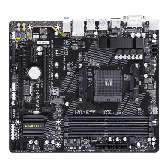
Page 4: Ga-Ab350M-Ds3H V2 Motherboard Layout
GA-AB350M-DS3H V2 Motherboard Layout CPU_FAN KB_MS_USB ATX_12V Socket AM4 HDMI R_USB30_1 R_USB30_2 SYS_FAN1 USB_LAN M_BIOS AUDIO M2F_32G GA-AB350M-DS3H V2 PCIEX16 Realtek ® GbE LAN SATA3 PCIEX1 ® AMD B350 Super I/O SATA3 CODEC PCIEX4 CLR_CMOS SPDIF_O F_PANEL LED_C F_USB1 F_AUDIO…
-
Page 5: Chapter 1 Hardware Installation
Chapter 1 Hardware Installation Installation Precautions The motherboard contains numerous delicate electronic circuits and components which can become damaged as a result of electrostatic discharge (ESD). Prior to installation, carefully read the user’s manual and follow these procedures: • Prior to installation, make sure the chassis is suitable for the motherboard. •…
-
Page 6: 1-2 Product Specifications
Š non-ECC mode) Support for non-ECC Un-buffered DIMM 1Rx8/2Rx8/1Rx16 memory modules Š Support for Extreme Memory Profile (XMP) memory modules Š (Go to GIGABYTE’s website for the latest supported memory speeds and memory modules.) Onboard Integrated Graphics Processor: Š 1 x DVI-D port, supporting a maximum resolution of 1920×1200@60 Hz Graphics * The DVI-D port does not support D-Sub connection by adapter.
-
Page 7
Internal 1 x 24-pin ATX main power connector Š 1 x 8-pin ATX 12V power connector Connectors Š 1 x CPU fan header Š 1 x system fan header Š 1 x M.2 Socket 3 connector Š 4 x SATA 6Gb/s connectors Š… -
Page 8
Support for Windows 10 64-bit Š Support for Windows 7 64-bit System Š * Please download the «Windows USB Installation Tool» from GIGABYTE’s website and install it before installing Windows 7. Form Factor Micro ATX Form Factor; 24.4cm x 21.5cm Š… -
Page 9: Installing The Cpu
• Make sure that the motherboard supports the memory. It is recommended that memory of the same capacity, brand, speed, and chips be used. (Go to GIGABYTE’s website for the latest supported memory speeds and memory modules.) • Always turn off the computer and unplug the power cord from the power outlet before installing the memory to prevent hardware damage.
-
Page 10: Installing An Expansion Card
Dual Channel Memory Configurations Table: DDR4_4 DDR4_2 DDR4_3 DDR4_1 2 Modules DS/SS DS/SS DS/SS DS/SS 4 Modules DS/SS DS/SS DS/SS DS/SS (SS=Single-Sided, DS=Double-Sided, «- -«=No Memory) Due to CPU limitations, read the following guidelines before installing the memory in Dual Channel mode. Dual Channel mode cannot be enabled if only one memory module is installed. When enabling Dual Channel mode with two or four memory modules, it is recommended that memory of the same capacity, brand, speed, and chips be used.
-
Page 11
• When removing the cable, pull it straight out from the connector. Do not rock it side to side to prevent an electrical short inside the cable connector. To configure 7.1-channel audio, you have to use an HD front panel audio module and enable the multi-channel audio feature through the audio driver. Please visit GIGABYTE’s website for details on configuring the audio software. — 11 -… -
Page 12: Internal Connectors
Internal Connectors ATX_12V F_PANEL F_AUDIO CPU_FAN F_USB30 SYS_FAN1 F_USB1/F_USB2 LED_C SATA3 0/1/2/3 M2F_32G SPDIF_O CLR_CMOS Read the following guidelines before connecting external devices: • First make sure your devices are compliant with the connectors you wish to connect. • Before installing the devices, be sure to turn off the devices and your computer. Unplug the power cord from the power outlet to prevent damage to the devices.
-
Page 13
1/2) ATX_12V/ATX (2×4 12V Power Connector and 2×12 Main Power Connector) With the use of the power connector, the power supply can supply enough stable power to all the components on the motherboard. Before connecting the power connector, first make sure the power supply is turned off and all devices are properly installed. The power connector possesses a foolproof design. Connect the power supply cable to the power connector in the correct orientation. -
Page 14
3/4) CPU_FAN/SYS_FAN1 (Fan Headers) All fan headers on this motherboard are 4-pin. Most fan headers possess a foolproof insertion design. When connecting a fan cable, be sure to connect it in the correct orientation (the black connector wire is the ground wire). The motherboard supports CPU fan speed control, which requires the use of a CPU fan with fan speed control design. -
Page 15
6) SATA3 0/1/2/3 (SATA 6Gb/s Connectors) The SATA connectors conform to SATA 6Gb/s standard and are compatible with SATA 3Gb/s and SATA 1.5Gb/s standard. Each SATA connector supports a single SATA device. The SATA connectors support RAID 0, RAID 1, and RAID 10. Refer to Chapter 3, «Configuring a RAID Set,» for instructions on configuring F_USB3 F a RAID array. SATA3 Pin No. -
Page 16
 SPDIF_O (S/PDIF Out Header) This header supports digital S/PDIF Out and connects a S/PDIF digital audio cable (provided by expansion cards) for digital audio output from your motherboard to certain expansion cards like graphics cards and sound cards. For example, some graphics cards may require you to use a S/PDIF digital audio cable for digital audio output from your motherboard to your graphics card if you wish to connect an HDMI display to the graphics card and have digital audio output from the HDMI display at the same time.
 -
Page 17
10) F_AUDIO (Front Panel Audio Header) The front panel audio header supports High Definition audio (HD). You may connect your chassis front panel audio module to this header. Make sure the wire assignments of the module connector match the pin assignments of the motherboard header. Incorrect connection between the module connector and the motherboard header will make the device unable to work or even damage it. Pin No. -
Page 18
12) F_USB1/F_USB2 (USB 2.0/1.1 Headers) The headers conform to USB 2.0/1.1 specification. Each USB header can provide two USB ports via an optional USB bracket. For purchasing the optional USB bracket, please contact the local dealer. Pin No. Definition Pin No. Definition Power (5V) USB DY+ Power (5V) USB DX- USB DY- No Pin USB DX+ •… -
Page 19
14) TPM (Trusted Platform Module Header) You may connect a TPM (Trusted Platform Module) to this header. Pin No. Definition Pin No. Definition LCLK LAD0 LFRAME No Pin LRESET SB3V DEBUG PORT SERIRQ LAD3 LAD2 VCC3 LAD1 15) BAT (Battery) The battery provides power to keep the values (such as BIOS configurations, date, and time information) in the CMOS when the computer is turned off. Replace the battery when the battery voltage drops to a low level, or the CMOS values may not be accurate or may be lost. -
Page 20
16) CLR_CMOS (Clear CMOS Jumper) Use this jumper to clear the BIOS configuration and reset the CMOS values to factory defaults. To clear the CMOS values, use a metal object like a screwdriver to touch the two pins for a few seconds. Open: Normal Short: Clear CMOS Values • Always turn off your computer and unplug the power cord from the power outlet before clearing the CMOS values. -
Page 21: Chapter 2 Bios Setup
To access the BIOS Setup program, press the <Delete> key during the POST when the power is turned on. To upgrade the BIOS, use either the GIGABYTE Q-Flash or @BIOS utility. Q-Flash allows the user to quickly and easily upgrade or back up BIOS without entering the operating system.
-
Page 22: The Main Menu
The Main Menu System Time Setup Menus Hardware Informa- tion Configuration Items Current Settings Quick Access Bar allows you to enter Easy Mode, select BIOS default language, configure fan settings, or enter Q-Flash. Classic Setup Function Keys <f><g> Move the selection bar to select a setup menu <h><i>…
-
Page 23
M.I.T. Whether the system will work stably with the overclock/overvoltage settings you made is dependent on your overall system configurations. Incorrectly doing overclock/overvoltage may result in damage to CPU, chipset, or memory and reduce the useful life of these components. This page is for advanced users only and we recommend you not to alter the default settings to prevent system instability or other unexpected results. -
Page 24
& AMD Cool&Quiet function Lets the AMD Cool’n’Quiet driver dynamically adjust the CPU clock and VID to Enabled reduce heat output from your computer and its power consumption. (Default) Disables this function. Disabled & SVM Mode Virtualization enhanced by Virtualization Technology will allow a platform to run multiple operating systems and applications in independent partitions. With virtualization, one computer system can function as multiple virtual systems. (Default: Disabled) &… -
Page 25
Manual and Advanced Manual allow the Channel Interleaving , Rank Interleaving , and memory (Note) (Note) (Note) timing settings below to be configurable. Options are: Auto (default), Manual, Advanced Manual (Note) & Profile DDR Voltage When using a non-XMP memory module or Extreme Memory Profile (X.M.P.) is set to Disabled, the value is displayed according to your memory specification. When Extreme Memory Profile (X.M.P.) is set to Profile1 or Profile2, the value is displayed according to the SPD data on the XMP memory. &… -
Page 26
& PCIe Slot Configuration Allows you to set the operation mode of the PCI Express slots to Gen 1, Gen 2, or Gen 3. Actual operation mode is subject to the hardware specification of each slot. Auto lets the BIOS automatically configure this setting. (Default: Auto) & 3DMark01 Enhancement Allows you to determine whether to enhance some legacy benchmark performance. (Default: Disabled) ` Smart Fan 5 Settings &… -
Page 27: System
System This section provides information on your motherboard model and BIOS version. You can also select the default language used by the BIOS and manually set the system time. & System Language Selects the default language used by the BIOS. &…
-
Page 28: Bios
System program. (Default) & Full Screen LOGO Show Allows you to determine whether to display the GIGABYTE Logo at system startup. Disabled skips the GIGABYTE Logo when the system starts up. (Default: Enabled) & Fast Boot Enables or disables Fast Boot to shorten the OS boot process. Ultra Fast provides the fastest bootup speed.
-
Page 29
& SATA Support All Sata Devices All SATA devices are functional in the operating system and during the POST. Last Boot HDD Only Except for the previous boot drive, all SATA devices are disabled before the OS boot process completes. (Default) This item is configurable only when Fast Boot is set to Enabled or Ultra Fast. -
Page 30
& Network Stack Disables or enables booting from the network to install a GPT format OS, such as installing the OS from the Windows Deployment Services server. (Default: Disabled) & Ipv4 PXE Support Enables or disables IPv4 PXE Support. This item is configurable only when Network Stack is enabled. & Ipv4 HTTP Support Enables or disables HTTP boot support for IPv4. This item is configurable only when Network Stack is enabled. -
Page 31: Peripherals
Peripherals & AMD CPU fTPM Enables or disables the TPM 2.0 function integrated in the AMD CPU. (Default: Disabled) & Initial Display Output (Note) Specifies the first initiation of the monitor display from the installed PCI Express graphics card or the onboard graphics. IGD Video Sets the onboard graphics as the first display. Sets the graphics card on the PCIEX16 slot as the first display. (Default) PCIe 1 Slot & RGB Fusion (Onboard LED) Allows you to set the LED lighting mode for the motherboard. Enables this function.
-
Page 32
& USB Mass Storage Driver Support Enables or disables support for USB storage devices. (Default: Enabled) & Mass Storage Devices Displays a list of connected USB mass storage devices. This item appears only when a USB storage device is installed. &… -
Page 33: Chipset
Chipset & IOMMU Enables or disables AMD IOMMU support. (Default: Auto) & Integrated Graphics (Note) Enables or disables the onboard graphics function. The BIOS will automatically enable or disable the onboard graphics depending on the Auto graphics card being installed. (Default) Disables the onboard graphics.
-
Page 34: Power
Power & AC BACK Determines the state of the system after the return of power from an AC power loss. The system returns to its last known awake state upon the return of the AC power. Memory Always On The system is turned on upon the return of the AC power. Always Off The system stays off upon the return of the AC power.
-
Page 35
& Soft-Off by PWR-BTTN Configures the way to turn off the computer in MS-DOS mode using the power button. Press the power button and then the system will be turned off instantly. (Default) Instant-Off Delay 4 Sec. Press and hold the power button for 4 seconds to turn off the system. If the power button is pressed for less than 4 seconds, the system will enter suspend mode. -
Page 36: Save & Exit
Save & Exit & Save & Exit Setup Press <Enter> on this item and select Yes. This saves the changes to the CMOS and exits the BIOS Setup program. Select No or press <Esc> to return to the BIOS Setup Main Menu. &…
-
Page 37: Chapter 3 Appendix
Chapter 3 Appendix 3-1 Configuring a RAID Set RAID Levels RAID 0 RAID 1 RAID 10 Minimum Number of ≥2 Hard Drives Array Capacity Number of hard drives * Size of the smallest drive (Number of hard drives/2) * Size of the smallest drive Size of the smallest drive Fault Tolerance Before you begin, please prepare the following items: •…
-
Page 38
3. Insert the USB thumb drive and then browse to the location of the driver. The location of the drivers is as follows: Hw10RAIDx64 4. Select AMD-RAID Bottom Device first and click Next to load the driver. Then select AMD-RAID Controller and click Next to load the driver. Finally, continue the OS installation. Please visit GIGABYTE’s website for details on configuring a RAID array. — 38 -… -
Page 39: Drivers Installation
You can click the Xpress Install button and «Xpress Install» will install all of the selected drivers. Or click the arrow icon to individually install the drivers you need. Please visit GIGABYTE’s website for Please visit GIGABYTE’s website for more software information.
-
Page 40: Regulatory Statements
Contravention will be prosecuted. We believe that the information contained herein was accurate in all respects at the time of printing. GIGABYTE cannot, however, assume any responsibility for errors or omissions in this text. Also note that the information in this document is subject to change without notice and should not be construed as a commitment by GIGABYTE.
-
Page 41
FCC Notice (U.S.A. Only) This equipment has been tested and found to comply with the limits for a Class B digital device, pursuant to Part 15 of the FCC Rules. These limits are designed to provide reasonable protection against harmful interference in a residential installation. This equipment generates, uses, and can radiate radio frequency energy and, if not installed and used in accordance with the instructions, may cause harmful interference to radio communications. -
Page 42: Contact Us
Contact Us GIGA-BYTE TECHNOLOGY CO., LTD. Address: No.6, Baoqiang Rd., Xindian Dist., New Taipei City 231, Taiwan TEL: +886-2-8912-4000, FAX: +886-2-8912-4005 Tech. and Non-Tech. Support (Sales/Marketing) : https://esupport.gigabyte.com WEB address (English): https://www.gigabyte.com WEB address (Chinese): https://www.gigabyte.com/tw GIGABYTE eSupport • To submit a technical or non-technical (Sales/Marketing) question, please link to: https://esupport.gigabyte.com…
 SPDIF_O (S/PDIF Out Header) This header supports digital S/PDIF Out and connects a S/PDIF digital audio cable (provided by expansion cards) for digital audio output from your motherboard to certain expansion cards like graphics cards and sound cards. For example, some graphics cards may require you to use a S/PDIF digital audio cable for digital audio output from your motherboard to your graphics card if you wish to connect an HDMI display to the graphics card and have digital audio output from the HDMI display at the same time.
 Посмотреть инструкция для Gigabyte GA-AB350M-DS3H V2 бесплатно. Руководство относится к категории Материнские платы, 1 человек(а) дали ему среднюю оценку 7.5. Руководство доступно на следующих языках: английский. У вас есть вопрос о Gigabyte GA-AB350M-DS3H V2 или вам нужна помощь? Задайте свой вопрос здесь
Не можете найти ответ на свой вопрос в руководстве? Вы можете найти ответ на свой вопрос ниже, в разделе часто задаваемых вопросов о Gigabyte GA-AB350M-DS3H V2.
Какие сертификаты Gigabyte GA-AB350M-DS3H V2 имеет?
Какая ширина Gigabyte GA-AB350M-DS3H V2?
Какая толщина Gigabyte GA-AB350M-DS3H V2?
Инструкция Gigabyte GA-AB350M-DS3H V2 доступно в русский?
Не нашли свой вопрос? Задайте свой вопрос здесь
 Loading…
![]()
GA-AB350M-DS3H V2
User’s Manual
Rev. 1101
For more product details, please visit GIGABYTE’s website.
To reduce the impacts on global warming, the packaging materials of this product are recyclable and reusable. GIGABYTE works with you to protect the environment.

Motherboard
GA-AB350M-DS3H V2
Motherboard
GA-AB350M-DS3H V2
Oct. 12, 2018
Oct. 12, 2018
Copyright
© 2018 GIGA-BYTE TECHNOLOGY CO., LTD. All rights reserved.
The trademarks mentioned in this manual are legally registered to their respective owners.
Disclaimer
Information in this manual is protected by copyright laws and is the property of GIGABYTE.
ChangestothespecificationsandfeaturesinthismanualmaybemadebyGIGABYTEwithoutpriornotice.
No part of this manual may be reproduced, copied, translated, transmitted, or published in any form or by any means without GIGABYTE’s prior written permission.
In order to assist in the use of this product, carefully read the User’s Manual.
For product-related information, check on our website at: https://www.gigabyte.com
Identifying Your Motherboard Revision
The revision number on your motherboard looks like this: «REV: X.X.» For example, «REV: 1.0» means the revision of the motherboard is 1.0. Check your motherboard revision before updating motherboard BIOS, drivers, or when looking for technical information.
Example:

Table of Contents
|
GA-AB350M-DS3H V2 Motherboard Layout |
…………………………………………………………..4 |
|
|
Chapter 1 Hardware Installation………………………………………………………………………….. |
5 |
|
|
1-1 |
Installation Precautions…………………………………………………………………………. |
5 |
|
1-2 |
Product Specifications………………………………………………………………………….. |
6 |
|
1-3 |
Installing the CPU………………………………………………………………………………… |
9 |
|
1-4 |
Installing the Memory……………………………………………………………………………. |
9 |
|
1-5 Installing an Expansion Card……………………………………………………………….. |
10 |
|
|
1-6 |
Back Panel Connectors………………………………………………………………………. |
10 |
|
1-7 |
Internal Connectors……………………………………………………………………………. |
12 |
|
Chapter 2 BIOS Setup……………………………………………………………………………………… |
21 |
|
|
2-1 |
Startup Screen…………………………………………………………………………………… |
21 |
|
2-2 |
The Main Menu………………………………………………………………………………….. |
22 |
|
2-3 |
M.I.T…………………………………………………………………………………………………. |
23 |
|
2-4 |
System……………………………………………………………………………………………… |
27 |
|
2-5 |
BIOS………………………………………………………………………………………………… |
28 |
|
2-6 |
Peripherals………………………………………………………………………………………… |
31 |
|
2-7 |
Chipset……………………………………………………………………………………………… |
33 |
|
2-8 |
Power……………………………………………………………………………………………….. |
34 |
|
2-9 |
Save & Exit……………………………………………………………………………………….. |
36 |
|
Chapter 3 Appendix…………………………………………………………………………………………. |
37 |
|
|
3-1 Configuring a RAID Set………………………………………………………………………. |
37 |
|
|
3-2 |
Drivers Installation……………………………………………………………………………… |
39 |
|
Regulatory Statements…………………………………………………………………………………. |
40 |
|
|
Contact Us………………………………………………………………………………………………….. |
42 |
— 3 —
GA-AB350M-DS3H V2 Motherboard Layout
|
KB_MS_USB |
CPU_FAN |
|
ATX_12V |
|
|
DVI |
Socket AM4 |
|
HDMI |
|||||
|
R_USB30_1 |
|||||
|
R_USB30_2 SYS_FAN1 |
|||||
|
USB_LAN |
|||||
|
M_BIOS |
M2F_32G |
||||
|
AUDIO |
GA-AB350M-DS3H V2 |
||||
|
110 |
80 |
60 |
42 |
||
|
Realtek® |
PCIEX16 |
||||
|
GbE LAN |
|||||
|
PCIEX1 |
BAT |
iTE® |
|||
|
CODEC |
PCIEX4 |
Super I/O |
|||
|
SPDIF_O |
|||||
|
LED_C |
COM |
F_USB1 |
|||
|
F_AUDIO |
TPM |
F_USB2 |
ATX
|
DDR4 4 DDR4 2 DDR4 3 |
DDR4 1 |
|
SATA3 |
|
|
3 |
|
|
AMD B350 |
|
|
CLR_CMOS |
2 SATA3 |
|
0 |
|
|
1 |
|
|
F_PANEL |
|
|
F_USB30 |
Box Contents
|
55 |
GA-AB350M-DS3H motherboard |
55 |
Two SATA cables |
|
55 |
Motherboard driver disk |
55 |
I/O Shield |
|
55 |
User’s Manual |
*The box contents above are for reference only and the actual items shall depend on the product package you obtain. The box contents are subject to change without notice.
—4 —

Chapter 1 Hardware Installation
1-1 Installation Precautions
The motherboard contains numerous delicate electronic circuits and components which can become damaged as a result of electrostatic discharge (ESD). Prior to installation, carefully read the user’s manual and follow these procedures:
•• Prior to installation, make sure the chassis is suitable for the motherboard.
•• Prior to installation, do not remove or break motherboard S/N (Serial Number) sticker or warranty sticker provided by your dealer. These stickers are required for warranty validation.
•• Always remove the AC power by unplugging the power cord from the power outlet before installing or removing the motherboard or other hardware components.
•• When connecting hardware components to the internal connectors on the motherboard, make sure they are connected tightly and securely.
•• When handling the motherboard, avoid touching any metal leads or connectors.
•• It is best to wear an electrostatic discharge (ESD) wrist strap when handling electronic components such as a motherboard, CPU or memory. If you do not have an ESD wrist strap, keep your hands dry and first touch a metal object to eliminate static electricity.
•• Prior to installing the motherboard, please have it on top of an antistatic pad or within an electrostatic shielding container.
•• Before connecting or unplugging the power supply cable from the motherboard, make sure the power supply has been turned off.
•• Before turning on the power, make sure the power supply voltage has been set according to the local voltage standard.
•• Before using the product, please verify that all cables and power connectors of your hardware components are connected.
•• To prevent damage to the motherboard, do not allow screws to come in contact with the motherboard circuit or its components.
•• Make sure there are no leftover screws or metal components placed on the motherboard or within the computer casing.
•• Do not place the computer system on an uneven surface.
•• Do not place the computer system in a high-temperature or wet environment.
•• Turning on the computer power during the installation process can lead to damage to system components as well as physical harm to the user.
•• If you are uncertain about any installation steps or have a problem related to the use of the product, please consult a certified computer technician.
•• If you use an adapter, extension power cable, or power strip, ensure to consult with its installation and/or grounding instructions.
— 5 —
1-2 Product Specifications
|
CPU |
AM4 Socket: |
|
— AMD Ryzen™ processor |
—AMD 7th Generation A-series/Athlon™ processors
(Go to GIGABYTE’s website for the latest CPU support list.)
|
Chipset |
AMD B350 |
||
|
Memory |
4 x DDR4 DIMM sockets supporting up to 64 GB of system memory |
||
|
Dual channel memory architecture |
|||
|
Support for DDR4 2667 (Note 1)/2400/2133 MHz memory modules |
|||
|
Support for ECC Un-buffered DIMM 1Rx8/2Rx8 memory modules (operate in |
|||
|
non-ECC mode) |
|||
|
Support for non-ECC Un-buffered DIMM 1Rx8/2Rx8/1Rx16 memory modules |
|||
|
Support for Extreme Memory Profile (XMP) memory modules |
|||
|
(Go to GIGABYTE’s website for the latest supported memory speeds and memory |
|||
|
modules.) |
|||
|
Onboard |
Integrated Graphics Processor: |
||
|
Graphics |
— |
1 x DVI-D port, supporting a maximum resolution of 1920×1200@60 Hz |
|
|
* The DVI-D port does not support D-Sub connection by adapter. |
|||
|
— |
1 x HDMI port, supporting a maximum resolution of 4096×2160@24 Hz |
||
|
* Support for HDMI 1.4 version. |
|||
|
Maximum shared memory of 2 GB |
|||
|
Audio |
Realtek® ALC887 codec |
||
|
High Definition Audio |
|||
|
2/4/5.1/7.1-channel |
|||
|
* To configure 7.1-channel audio, you have to use an HD front panel audio module |
|||
|
and enable the multi-channel audio feature through the audio driver. |
|||
|
Support for S/PDIF Out |
|||
|
LAN |
Realtek® GbE LAN chip (10/100/1000 Mbit) |
||
|
Expansion Slots |
1 x PCI Express x16 slot, running at x16 (PCIEX16) (Note 1) |
||
|
* For optimum performance, if only one PCI Express graphics card is to be installed, |
|||
|
be sure to install it in the PCIEX16 slot. |
(The PCIEX16 slot conforms to PCI Express 3.0 standard.)
1 x PCI Express x16 slot, running at x4 (PCIEX4)
1 x PCI Express x1 slot
(The PCIEX4 and PCI Express x1 slots conform to PCI Express 2.0 standard.)
Storage Interface 1 x M.2 connector (Socket 3, M key, type 2242/2260/2280/22110 SATA and PCIe x4/x2 (Note 2) SSD support)
4 x SATA 6Gb/s connectors
Support for RAID 0, RAID 1, and RAID 10
*Refer to «1-7 Internal Connectors,» for the installation notices for the M.2 and SATA connectors.
|
USB |
Chipset: |
||
|
— 2 x USB 3.1 |
Gen 1 ports available through the internal USB header |
||
|
— 8 x USB 2.0/1.1 ports (4 ports on the back panel, 4 ports available through |
|||
|
the internal USB headers) |
|||
|
CPU: |
|||
|
— 4 x USB 3.1 |
Gen 1 ports on the back panel |
(Note 1) Actual support may vary by CPU.
(Note 2) Supports only M.2 SATA SSDs when using an AMD 7th Generation A-series or Athlon™ processor. — 6 —
1 x 24-pin ATX main power connector
1 x 8-pin ATX 12V power connector
1 x CPU fan header
1 x system fan header
1 x M.2 Socket 3 connector
4 x SATA 6Gb/s connectors
1 x front panel header
1 x front panel audio header
1 x S/PDIF Out header
1 x RGB LED strip header
1 x USB 3.1 Gen 1 header
2 x USB 2.0/1.1 headers
1 x Trusted Platform Module (TPM) header (2×10 pin, for the GC-TPM2.0 module only)
1 x serial port header
1 x Clear CMOS jumper
|
Back Panel |
1 x PS/2 keyboard/mouse port |
|
Connectors |
1 x DVI-D port |
|
1 x HDMI port |
|
|
4 x USB 3.1 Gen 1 ports |
|
|
4 x USB 2.0/1.1 ports |
|
|
1 x RJ-45 port |
|
|
3 x audio jacks |
|
|
I/O Controller |
iTE® I/O Controller Chip |
Voltage detection
Temperature detection
Fan speed detection
Overheating warning
Fan fail warning
Fan speed control
*Whether the fan speed control function is supported will depend on the cooler you install.
|
BIOS |
1 x 128 Mbit flash |
|
|
Use of licensed AMI UEFI BIOS |
||
|
PnP 1.0a, DMI 2.7, WfM 2.0, SM BIOS 2.7, ACPI 5.0 |
||
|
Unique Features |
Support for APP Center |
|
* Available applications in APP Center may vary by motherboard model. Supported |
|
|
functions of each application may also vary depending on motherboard specifications. |
|
|
— |
@BIOS |
|
— |
3D OSD |
|
— |
AutoGreen |
|
— |
BIOS Setup |
|
— |
Cloud Station |
|
— |
Color Temperature |
|
— |
EasyTune |
|
— |
Fast Boot |
— 7 —
|
Unique Features |
— |
Game Boost |
|
— |
ON/OFF Charge |
|
|
— |
RGB Fusion |
|
|
— |
Smart Backup |
|
|
— |
Smart Keyboard |
|
|
— |
Smart TimeLock |
|
|
— |
System Information Viewer |
|
|
— |
USB Blocker |
|
|
— |
V-Tuner |
|
|
Support for Q-Flash |
||
|
Support for Xpress Install |
||
|
Bundled |
Norton® Internet Security (OEM version) |
|
|
Software |
cFosSpeed |
|
|
Operating |
Support for Windows 10 64-bit |
|
|
System |
Support for Windows 7 64-bit |
* Please download the «Windows USB Installation Tool» from GIGABYTE’s website and install it before installing Windows 7.
|
Form Factor |
Micro ATX Form Factor; 24.4cm x 21.5cm |
*GIGABYTE reserves the right to make any changes to the product specifications and product-related information without prior notice.
Please visit GIGABYTE’s website for support lists of CPU, memory modules, SSDs, and M.2 devices.
— 8 —
Please visit the SupportUtility List page on GIGABYTE’s website to download the latest version of apps.
|
1-3 |
Installing the CPU |
|
|
Read the following guidelines before you begin to install the CPU: |
||
|
•• |
Make sure that the motherboard supports the CPU. |
|
|
(Go to GIGABYTE’s website for the latest CPU support list.) |
||
|
•• |
Always turn off the computer and unplug the power cord from the power outlet before installing the |
|
|
•• |
CPU to prevent hardware damage. |
|
|
Locate the pin one of the CPU. The CPU cannot be inserted if oriented incorrectly. |
||
|
•• |
Apply an even and thin layer of thermal grease on the surface of the CPU. |
|
|
•• |
Do not turn on the computer if the CPU cooler is not installed, otherwise overheating and damage |
|
|
•• |
of the CPU may occur. |
|
|
Set the CPU host frequency in accordance with the CPU specifications. It is not recommended |
||
|
that the system bus frequency be set beyond hardware specifications since it does not meet the |
||
|
standard requirements for the peripherals. If you wish to set the frequency beyond the standard |
||
|
specifications, please do so according to your hardware specifications including the CPU, graphics |
||
|
card, memory, hard drive, etc. |
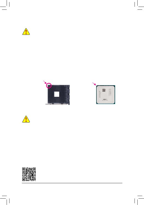
Installing the CPU
Locate the pin one (denoted by a small triangle) of the CPU socket and the CPU.
|
A Small Triangle Marking |
A Small Triangle Marking |
|||
|
Denotes Pin One of the |
AM4 Socket |
AM4 CPU |
||
|
Denotes CPU Pin One |
||||
|
Socket |
1-4 Installing the Memory
Read the following guidelines before you begin to install the memory:
•• Make sure that the motherboard supports the memory. It is recommended that memory of the same capacity, brand, speed, and chips be used.
(Go to GIGABYTE’s website for the latest supported memory speeds and memory modules.)
•• Always turn off the computer and unplug the power cord from the power outlet before installing the memory to prevent hardware damage.
•• Memory modules have a foolproof design. A memory module can be installed in only one direction. If you are unable to insert the memory, switch the direction.
Dual Channel Memory Configuration
This motherboard provides four memory sockets and supports Dual Channel Technology. After the memory is installed, the BIOS will automatically detect the specifications and capacity of the memory. Enabling Dual
Channel memory mode will double the original memory bandwidth.
The four memory sockets are divided into two channels and each channel has two memory sockets as following:
Channel A: DDR4_2, DDR4_4Channel B: DDR4_1, DDR4_3
Please visit GIGABYTE’s website for details on hardware installation.
— 9 —
Dual Channel Memory Configurations Table:
|
DDR4_4 |
DDR4_2 |
DDR4_3 |
DDR4_1 |
|
|
2 Modules |
— — |
DS/SS |
— — |
DS/SS |
|
DS/SS |
— — |
DS/SS |
— — |
|
|
4 Modules |
DS/SS |
DS/SS |
DS/SS |
DS/SS |
(SS=Single-Sided, DS=Double-Sided, «- -«=No Memory)
Due to CPU limitations, read the following guidelines before installing the memory in Dual Channel mode.
1.Dual Channel mode cannot be enabled if only one memory module is installed.
2.When enabling Dual Channel mode with two or four memory modules, it is recommended that memory of the same capacity, brand, speed, and chips be used. For optimum performance, when enabling
Dual Channel mode with two memory modules, we recommend that you install them in the DDR4_1 and DDR4_2 sockets.
1-5 Installing an Expansion Card
Read the following guidelines before you begin to install an expansion card:
•• Make sure the motherboard supports the expansion card. Carefully read the manual that came with your expansion card.
•• Always turn off the computer and unplug the power cord from the power outlet before installing an expansion card to prevent hardware damage.
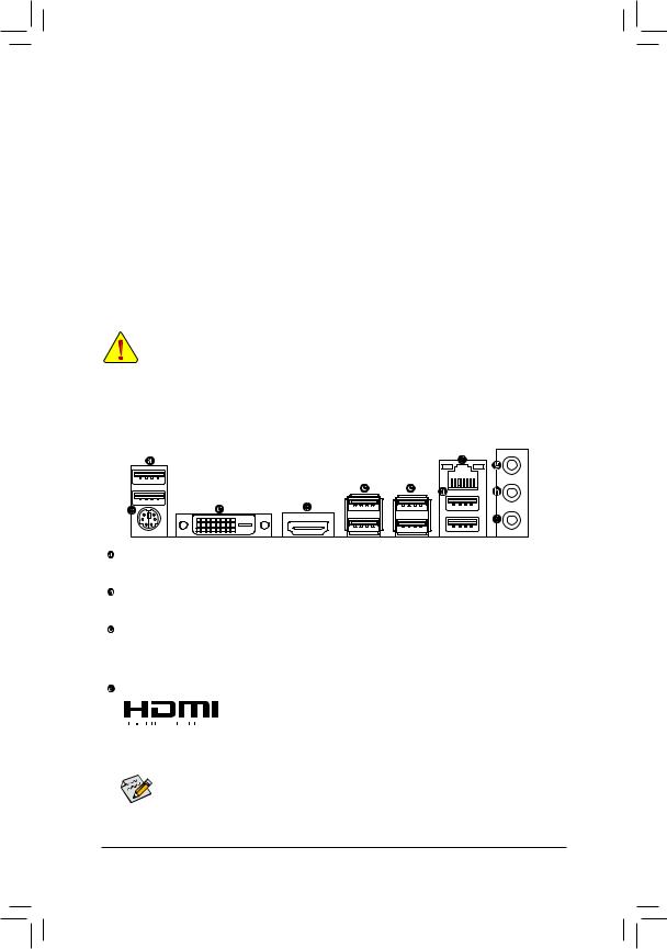
1-6 Back Panel Connectors
USB 2.0/1.1 Port
The USB port supports the USB 2.0/1.1 specification. Use this port for USB devices.
PS/2 Keyboard/Mouse Port
Use this port to connect a PS/2 mouse or keyboard.
DVI-D Port (Note)
The DVI-D port conforms to the DVI-D specification and supports a maximum resolution of 1920×1200@60 Hz
(the actual resolutions supported depend on the monitor being used). Connect a monitor that supports DVI-D connection to this port.
HDMI Port
 The HDMI port is HDCP compliant and supports Dolby TrueHD and DTS HD


 Master Audio formats. It also supports up to 192KHz/24bit 8-channel LPCM audio output. You can use this port to connect your HDMI-supported monitor. The maximum supported resolution is 4096×2160@24 Hz, but the actual resolutions supported are dependent on the monitor being used.
After installing the HDMI device, make sure to set the default sound playback device to HDMI. (The item name may differ depending on your operating system.)
(Note) The DVI-D port does not support D-Sub connection by adapter.
— 10 —
![]()
USB 3.1 Gen 1 Port
The USB 3.1 Gen 1 port supports the USB 3.1 Gen 1 specification and is compatible to the USB 2.0 specification. Use this port for USB devices.
RJ-45 LAN Port
The Gigabit Ethernet LAN port provides Internet connection at up to 1 Gbps data rate. The following describes the states of the LAN port LEDs.
|
Connection/ |
Connection/Speed LED: |
Activity LED: |
|||||||||||||||||
|
Speed LED |
Activity LED |
||||||||||||||||||
|
State |
Description |
State |
Description |
||||||||||||||||
|
Orange |
1 Gbps data rate |
Blinking |
Data transmission or receiving is occurring |
||||||||||||||||
|
Green |
100 Mbps data rate |
Off |
No data transmission or receiving is occurring |
||||||||||||||||
|
Off |
10 Mbps data rate |
||||||||||||||||||
|
LAN Port |
|||||||||||||||||||
Line In/Rear Speaker Out (Blue)
The line in jack. Use this audio jack for line in devices such as an optical drive, walkman, etc.
Line Out/Front Speaker Out (Green)
The line out jack.
Mic In/Center/Subwoofer Speaker Out (Pink)
The Mic in jack.
Audio Jack Configurations:
|
Jack |
Headphone/ |
4-channel |
5.1-channel |
7-channel |
|
|
2-channel |
|||||
|
Line In/Rear Speaker Out |
a |
a |
a |
||
|
Line Out/Front Speaker Out |
a |
a |
a |
a |
|
|
Mic In/Center/Subwoofer |
a |
a |
|||
|
Speaker Out |
|||||
|
Front Panel Line Out/ |
a |
||||
|
Side Speaker Out |
|||||
•• When removing the cable connected to a back panel connector, first remove the cable from your device and then remove it from the motherboard.
•• When removing the cable, pull it straight out from the connector. Do not rock it side to side to prevent an electrical short inside the cable connector.

 To configure 7.1-channel audio, you have to use an HD front panel audio module and enable the
  multi-channel audio feature through the audio driver.
Please visit GIGABYTE’s website for details on configuring the audio software.
— 11 —
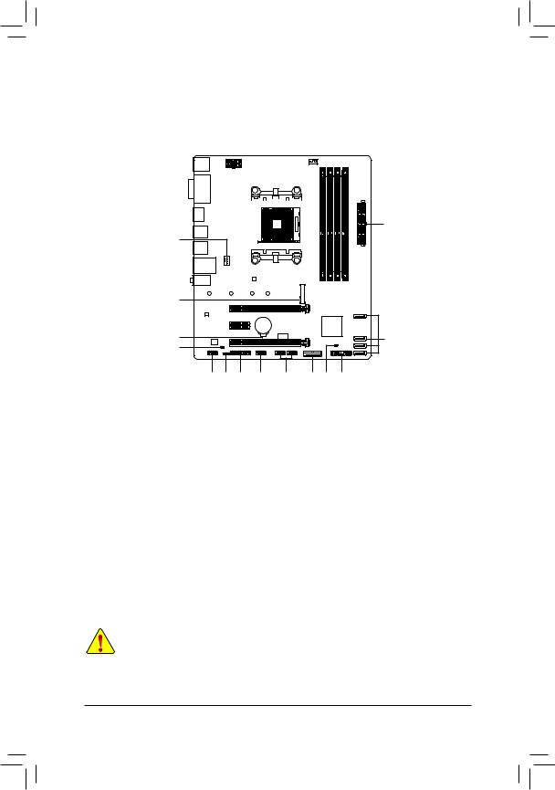
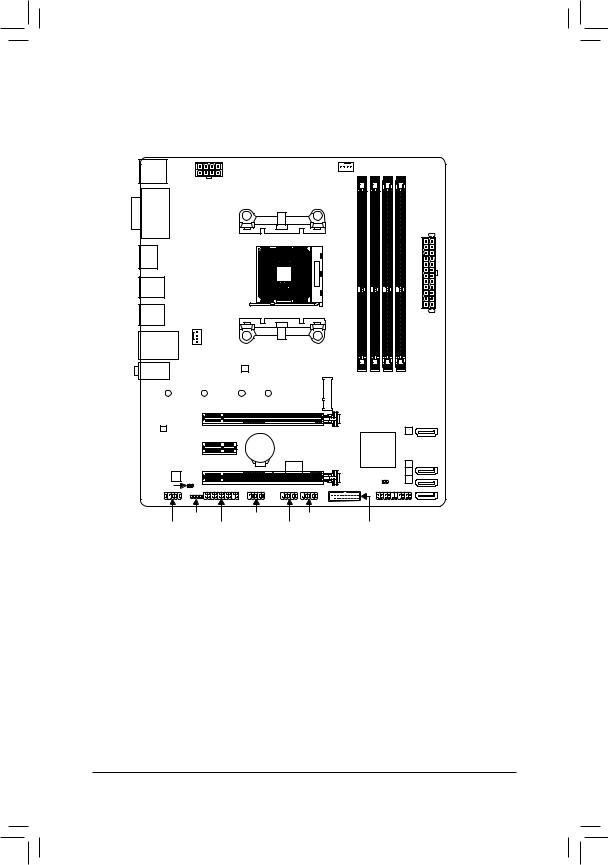
1-7 Internal Connectors
|
1 |
3 |
||||||||||
2
4
|
7 |
|||||||
|
15 |
6 |
||||||
|
8 |
|||||||
|
10 |
5 |
14 |
13 |
12 |
11 |
16 |
9 |
|
1) |
ATX_12V |
9) |
F_PANEL |
|
2) |
ATX |
10) |
F_AUDIO |
|
3) |
CPU_FAN |
11) |
F_USB30 |
|
4) |
SYS_FAN1 |
12) |
F_USB1/F_USB2 |
|
5) |
LED_C |
13) |
COM |
|
6) |
SATA3 0/1/2/3 |
14) |
TPM |
|
7) |
M2F_32G |
15) |
BAT |
|
|
SPDIF_O |
16) |
CLR_CMOS |
Read the following guidelines before connecting external devices:
•• First make sure your devices are compliant with the connectors you wish to connect.
•• Before installing the devices, be sure to turn off the devices and your computer. Unplug the power cord from the power outlet to prevent damage to the devices.
•• After installing the device and before turning on the computer, make sure the device cable has been securely attached to the connector on the motherboard.
— 12 —
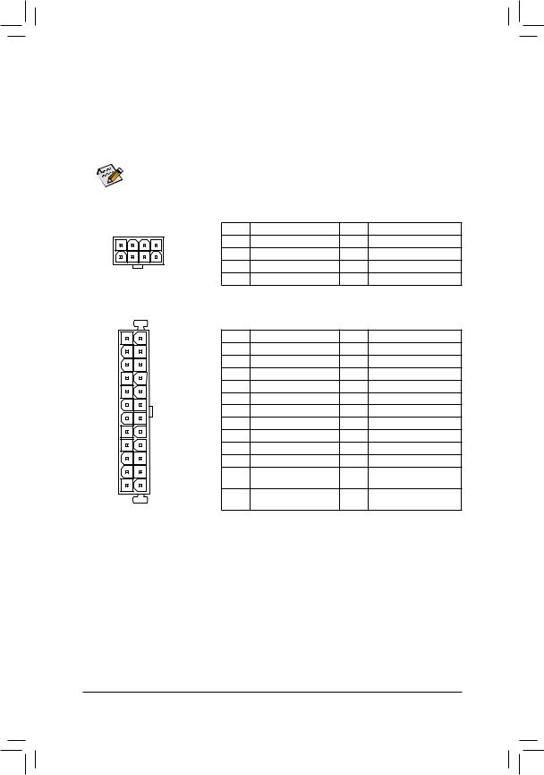
1/2) ATX_12V/ATX (2×4 12V Power Connector and 2×12 Main Power Connector)
With the use of the power connector, the power supply can supply enough stable power to all the components on the motherboard. Before connecting the power connector, first make sure the power supply is turned off and all devices are properly installed. The power connector possesses a foolproof design. Connect the power supply cable to the power connector in the correct orientation.
The 12V power connector mainly supplies power to the CPU. If the 12V power connector is not connected, the computer will not start.
 To meet expansion requirements, it is recommended that a power supply that can withstand high
  power consumption be used (500W or greater). If a power supply is used that does not provide the required power, the result can lead to an unstable or unbootable system.
|
ATX_12V: |
||||||
|
4 |
1 |
Pin No. |
Definition |
Pin No. |
Definition |
|
|
1 |
GND (Only for 2×4-pin 12V) |
5 |
+12V (Only for 2×4-pin 12V) |
|||
|
2 |
GND (Only for 2×4-pin 12V) |
6 |
+12V (Only for 2×4-pin 12V) |
|||
|
8 |
5 |
3 |
GND |
7 |
+12V |
|
|
4 |
GND |
8 |
+12V |
|||
|
ATX_12V |
||||||
|
ATX: |
||||||
|
12 |
24 |
Pin No. |
Definition |
Pin No. |
Definition |
|
|
1 |
3.3V |
13 |
3.3V |
|||
|
2 |
3.3V |
14 |
-12V |
|||
|
3 |
GND |
15 |
GND |
|||
|
4 |
+5V |
16 |
PS_ON (soft On/Off) |
|||
|
5 |
GND |
17 |
GND |
|||
|
6 |
+5V |
18 |
GND |
|||
|
7 |
GND |
19 |
GND |
|||
|
8 |
Power Good |
20 |
NC |
|||
|
9 |
5VSB (stand by +5V) |
21 |
+5V |
|||
|
10 |
+12V |
22 |
+5V |
|||
|
11 |
+12V (Only for 2×12-pin |
23 |
+5V (Only for 2×12-pin ATX) |
|||
|
1 |
13 |
12 |
ATX) |
24 |
GND (Only for 2×12-pin ATX) |
|
|
3.3V (Only for 2×12-pin |
||||||
|
ATX |
ATX) |
|||||
— 13 —