-
Драйверы
31
-
Инструкции по эксплуатации
18
Языки:

Gigabyte GA-H77M-D3H инструкция по эксплуатации
(72 страницы)
- Языки:Венгерский, Греческий, Испанский, Итальянский, Немецкий, Польский, Португальский, Русский, Турецкий, Французский, Чешский
-
Тип:
PDF -
Размер:
18.6 MB -
Описание:
Installation Guidebook


На NoDevice можно скачать инструкцию по эксплуатации для Gigabyte GA-H77M-D3H. Руководство пользователя необходимо для ознакомления с правилами установки и эксплуатации Gigabyte GA-H77M-D3H. Инструкции по использованию помогут правильно настроить Gigabyte GA-H77M-D3H, исправить ошибки и выявить неполадки.

-
Contents
-
Table of Contents
-
Troubleshooting
-
Bookmarks
Quick Links
GA-Z77M-D3H-MVP
GA-Z77M-D3H
GA-H77M-D3H
User’s Manual
Rev. 1002
12ME-H77MD3H-1002R
Related Manuals for Gigabyte GA-Z77M-D3H
Summary of Contents for Gigabyte GA-Z77M-D3H
-
Page 1
GA-Z77M-D3H-MVP GA-Z77M-D3H GA-H77M-D3H User’s Manual Rev. 1002 12ME-H77MD3H-1002R… -
Page 3: Identifying Motherboard Revision
GIGABYTE’s prior written permission. Documentation Classifications In order to assist in the use of this product, GIGABYTE provides the following types of documentations: For quick set-up of the product, read the Quick Installation Guide included with the product.
-
Page 4: Table Of Contents
Table of Contents Box Contents ……………………6 Optional Items …………………….6 GA-Z77M-D3H-MVP/GA-Z77M-D3H/GA-H77M-D3H Motherboard Layout ….7 GA-Z77M-D3H-MVP/GA-Z77M-D3H/GA-H77M-D3H Motherboard Block Diagram ..8 Chapter 1 Hardware Installation ………………9 Installation Precautions ………………9 Product Specifications ………………10 Installing the CPU and CPU Cooler …………… 13 1-3-1 Installing the CPU ………………..13…
-
Page 5
Chapter 3 Drivers Installation ………………53 Installing Chipset Drivers …………….53 Application Software ………………54 Technical Manuals ………………54 Contact ………………….55 System ………………….55 Download Center ………………. 56 New Program ………………..56 Chapter 4 Unique Features ……………….57 Xpress Recovery2 ………………57 BIOS Update Utilities ……………… -
Page 6: Box Contents
Box Contents GA-Z77M-D3H-MVP, GA-Z77M-D3H or GA-H77M-D3H motherboard Motherboard driver disk User’s Manual Quick Installation Guide Two SATA 6Gb/s cables I/O Shield The box contents above are for reference only and the actual items shall depend on the product package you obtain.
-
Page 7: Ga-Z77M-D3H-Mvp/Ga-Z77M-D3H/Ga-H77M-D3H Motherboard Layout
PCIEX16 Atheros SATA3 GbE LAN M_BIOS PCIEX1 B_BIOS Intel Z77MN ® Intel H77O SATA2 ® PCIe to PCI Bridge PCIEX4 CODEC CLR_CMOS F_AUDIO F_USB3 F_USB2 F_USB1 F_PANEL SPDIF_O Only for GA-Z77M-D3H-MVP. Only for GA-Z77M-D3H. Only for GA-H77M-D3H. — 7 -…
-
Page 8: Ga-Z77M-D3H-Mvp/Ga-Z77M-D3H/Ga-H77M-D3H Motherboard Block Diagram
PCIe to PCI Bridge CODEC PS/2 KB/Mouse PCI Bus 1 PCI Express x1 1 PCI Express x4 1 PCI Only for GA-Z77M-D3H-MVP. Only for GA-Z77M-D3H. Only for GA-H77M-D3H. For detailed product information/limitation(s), refer to “1-2 Product Specifications.” — 8 -…
-
Page 9: Chapter 1 Hardware Installation
Chapter 1 Hardware Installation Installation Precautions The motherboard contains numerous delicate electronic circuits and components which can become damaged as a result of electrostatic discharge (ESD). Prior to installation, carefully read the user’s manual and follow these procedures: Prior to installation, make sure the chassis is suitable for the motherboard. •…
-
Page 10: Product Specifications
Support for Extreme Memory Profile (XMP) memory modules Š * To support XMP memory, you must install an Intel 22nm (Ivy Bridge) CPU. O (Go to GIGABYTE’s website for the latest supported memory speeds and memory modules.) Onboard Integrated Graphics Processor: Š…
-
Page 11
Storage Interface Chipset: Š 2 x SATA 6Gb/s connectors (SATA3 0/1) supporting up to 2 SATA 6Gb/s devices 4 x SATA 3Gb/s connectors (SATA2 2/3/4/5) supporting up to 4 SATA 3Gb/s devices Support for RAID 0, RAID 1, RAID 5, and RAID 10 * When a RAID set is built across the SATA 6Gb/s and SATA 3Gb/s channels, the system performance of the RAID set may vary depending on the devices being connected. -
Page 12
Š ® System Form Factor Micro ATX Form Factor; 24.4cm x 22.0cm Š * GIGABYTE reserves the right to make any changes to the product specifications and product-related information without prior notice. Only for GA-Z77M-D3H-MVP. Hardware Installation — 12 -… -
Page 13: Installing The Cpu And Cpu Cooler
Read the following guidelines before you begin to install the CPU: Make sure that the motherboard supports the CPU. • (Go to GIGABYTE’s website for the latest CPU support list.) Always turn off the computer and unplug the power cord from the power outlet before installing the •…
-
Page 14
B. Follow the steps below to correctly install the CPU into the motherboard CPU socket. Before installing the CPU, make sure to turn off the computer and unplug the power cord from the power outlet to prevent damage to the CPU. Step 1: Step 2: Remove the CPU socket cover as shown. -
Page 15: Installing The Cpu Cooler
1-3-2 Installing the CPU Cooler Follow the steps below to correctly install the CPU cooler on the motherboard. (The following procedure uses Intel boxed cooler as the example cooler.) ® Male Push Pin Direction of the Arrow Sign The Top on the Male of Female Push Pin…
-
Page 16: Installing The Memory
Make sure that the motherboard supports the memory. It is recommended that memory of the same • capacity, brand, speed, and chips be used. (Go to GIGABYTE’s website for the latest supported memory speeds and memory modules.) Always turn off the computer and unplug the power cord from the power outlet before installing the •…
-
Page 17: Installing A Memory
1-4-2 Installing a Memory Before installing a memory module, make sure to turn off the computer and unplug the power cord from the power outlet to prevent damage to the memory module. DDR3 and DDR2 DIMMs are not compatible to each other or DDR DIMMs. Be sure to install DDR3 DIMMs on this motherboard. Notch DDR3 DIMM A DDR3 memory module has a notch, so it can only fit in one direction.
-
Page 18: Installing An Expansion Card
Installing an Expansion Card Read the following guidelines before you begin to install an expansion card: Make sure the motherboard supports the expansion card. Carefully read the manual that came • with your expansion card. Always turn off the computer and unplug the power cord from the power outlet before installing an •…
-
Page 19: Back Panel Connectors
Back Panel Connectors USB 2.0/1.1 Port The USB port supports the USB 2.0/1.1 specification. Use this port for USB devices such as a USB keyboard/mouse, USB printer, USB flash drive and etc. PS/2 Keyboard/Mouse Port Use this port to connect a PS/2 mouse or keyboard. D-Sub Port The D-Sub port supports a 15-pin D-Sub connector.
-
Page 20
Dual Display Configurations for the Onboard Graphics: This motherboard provides three video output ports: D-Sub, DVI-D, and HDMI. Dual monitor confgurations are supported in operating system environment only, but not during the BIOS Setup or POST process. USB 3.0/2.0 Port The USB 3.0 port supports the USB 3.0 specification and is compatible to the USB 2.0/1.1 specification. -
Page 21: Internal Connectors
Internal Connectors ATX_12V F_AUDIO SPDIF_O CPU_FAN F_USB30 SYS_FAN1/SYS_FAN2 F_USB1/2/3 SATA3 0/1 SATA2 2/3/4/5 F_PANEL CLR_CMOS Read the following guidelines before connecting external devices: First make sure your devices are compliant with the connectors you wish to connect. • Before installing the devices, be sure to turn off the devices and your computer. Unplug the power •…
-
Page 22
1/2) ATX_12V/ATX (2×2 12V Power Connector and 2×12 Main Power Connector) With the use of the power connector, the power supply can supply enough stable power to all the components on the motherboard. Before connecting the power connector, first make sure the power supply is turned off and all devices are properly installed. -
Page 23: Bat Battery
3/4) CPU_FAN/SYS_FAN1/SYS_FAN2 (Fan Headers) All fan headers on this motherboard are 4-pin. Most fan headers possess a foolproof insertion design. When connecting a fan cable, be sure to connect it in the correct orientation (the black connector wire is the ground wire). The speed control function requires the use of a fan with fan speed control design. For optimum heat dissipation, it is recommended that a system fan be installed inside the chassis.
-
Page 24
6) SATA3 0/1 (SATA 6Gb/s Connectors, Controlled by Intel Z77/H77 Chipset) The SATA connectors conform to SATA 6Gb/s standard and are compatible with SATA 3Gb/s and SATA 1.5Gb/s standard. Each SATA connector supports a single SATA device. The SATA3 0/1 connectors support RAID 0 and RAID 1. -
Page 25: F_Panel
 F_PANEL (Front Panel Header) Connect the power switch, reset switch, speaker, chassis intrusion switch/sensor and system status indicator on the chassis to this header according to the pin assignments below. Note the positive and negative pins before connecting the cables. Message/Power/ Power Sleep LED…
 -
Page 26: Front Panel Audio Header
9) F_AUDIO (Front Panel Audio Header) The front panel audio header supports Intel High Definition audio (HD) and AC’97 audio. You may connect your chassis front panel audio module to this header. Make sure the wire assignments of the module connector match the pin assignments of the motherboard header.
-
Page 27: Usb 2.0/1.1 Headers
11) F_USB30 (USB 3.0/2.0 Header) F_USB30 F_AUDIO(H) F_PANEL(NH) The header conforms to USB 3.0/2.0 specification and can provide two USB ports. For purchasing the optional 3.5″ front panel that provides two USB 3.0/2.0 ports, please contact the local dealer. Pin No. Definition Pin No.
-
Page 28
13) COM (Serial Port Header) The COM header can provide one serial port via an optional COM port cable. For purchasing the optional COM port cable, please contact the local dealer. Pin No. Definition NDCD- NSIN NSOUT NDTR- NDSR- NRTS- NCTS- NRI- No Pin… -
Page 29: Trusted Platform Module Header
15) TPM (Trusted Platform Module Header) You may connect a TPM (Trusted Platform Module) to this header. Pin No. Definition Pin No. Definition LCLK LAD0 LFRAME No Pin LRESET SB3V SERIRQ LAD3 LAD2 VCC3 LAD1 SUSCLK 16) CLR_CMOS (Clear CMOS Jumper) Use this jumper to clear the CMOS values (e.g.
-
Page 30
Hardware Installation — 30 -… -
Page 31: Chapter 2 Bios Setup
To access the BIOS Setup program, press the <Delete> key during the POST when the power is turned on. To upgrade the BIOS, use either the GIGABYTE Q-Flash or @BIOS utility. Q-Flash allows the user to quickly and easily upgrade or back up BIOS without entering the operating •…
-
Page 32: Startup Screen
Startup Screen The following startup Logo screen will appear when the computer boots. Function Keys Function Keys: <DEL>: BIOS SETUPQ-FLASH Press the <Delete> key to enter BIOS Setup or to access the Q-Flash utility in BIOS Setup. <F9>: SYSTEM INFORMATION Press the <F9>…
-
Page 33: The Main Menu
A. The 3D BIOS Screen (Default) On GIGABYTE’s uniquely designed 3D BIOS screen, you can use your mouse to move through the motherboard image and click to enter the function menu in each area for quick configuration. For example, pass your mouse arrow over the CPU and memory sockets and enter the System Tuning menu to configure CPU/memory frequency, memory timings, and voltage settings.
-
Page 34
BIOS Setup Program Function Keys Move the selection bar to select a setup menu <f><g> <h><i> Move the selection bar to select an configuration item on a menu <Enter> Execute command or enter a menu <+>/<Page Up> Increase the numeric value or make changes <->/<Page Down>… -
Page 35: M.i.t
M.I.T. Whether the system will work stably with the overclock/overvoltage settings you made is dependent on your overall system configurations. Incorrectly doing overclock/overvoltage may result in damage to CPU, chipset, or memory and reduce the useful life of these components. This page is for advanced users only and we recommend you not to alter the default settings to prevent system instability or other unexpected results.
-
Page 36
M.I.T. Current Status This screen provides information on CPU/memory frequencies/parameters. Advanced Frequency Settings Internal Graphics Clock & Allows you to set the onboard graphics clock. The adjustable range is from 400 MHz to 3000 MHz. (Default: Auto) CPU Clock Ratio &… -
Page 37
Advanced CPU Core Features CPU Clock Ratio, CPU Frequency & The settings under the two items above are synchronous to those under the same items on the Advanced Frequency Settings menu. Intel(R) Turbo Boost Technology (Note) & Allows you to determine whether to enable the Intel CPU Turbo Boost technology. Auto lets the BIOS automatically configure this setting. -
Page 38
CPU Enhanced Halt (C1E) (Note 1) & Enables or disables Intel CPU Enhanced Halt (C1E) function, a CPU power-saving function in system halt state. When enabled, the CPU core frequency and voltage will be reduced during system halt state to decrease power consumption. -
Page 39
Advanced Memory Settings Extreme Memory Profile (X.M.P.) , System Memory Multiplier (SPD), Memory (Note) & Frequency(Mhz) The settings under the three items above are synchronous to those under the same items on the Advanced Frequency Settings menu. Performance Enhance & Allows the system to operate at three different performance levels. -
Page 40
Channel A/B Timing Settings This sub-menu provides memory timing settings for each channel of memory. The respective timing setting screens are configurable only when DRAM Timing Selectable is set to Quick or Expert. Note: Your system may become unstable or fail to boot after you make changes on the memory timings. If this occurs, please reset the board to default values by loading optimized defaults or clearing the CMOS values. -
Page 41
PC Health Status Reset Case Open Status & Disabled Keeps or clears the record of previous chassis intrusion status. (Default) Enabled Clears the record of previous chassis intrusion status and the Case Open field will show «No» at next boot. Case Open &… -
Page 42
CPU Vcore/Dram Voltage/+3.3V/+12V & Displays the current system voltages. CPU/System Temperature & Displays current CPU/system temperature. CPU/System FAN Speed & Displays current CPU/system fan speeds. CPU Warning Temperature & Sets the warning threshold for CPU temperature. When CPU temperature exceeds the threshold, BIOS will emit warning sound. -
Page 43: System
System This section provides information on your CPU, memory, motherboard model, and BIOS version. You can also select the default language used by the BIOS and manually set the system time. System Language & Selects the default language used by the BIOS. System Date &…
-
Page 44: Bios Features
Enables or disables Numlock feature on the numeric keypad of the keyboard after the POST. (Default: Disabled) Full Screen LOGO Show & Allows you to determine whether to display the GIGABYTE Logo at system startup. Disabled skips the GIGABYTE Logo when the system starts up. (Default: Enabled) PCI ROM Priority &…
-
Page 45: Administrator Password
Limit CPUID Maximum (Note) & Allows you to determine whether to limit CPUID maximum value. Set this item to Disabled for Windows XP operating system; set this item to Enabled for legacy operating system such as Windows NT4.0. (Default: Disabled) Execute Disable Bit (Note) &…
-
Page 46: Peripherals
Peripherals LAN PXE Boot Option ROM & Allows you to decide whether to activate the boot ROM integrated with the onboard LAN chip. (Default: Disabled) SATA Controller(s) & Enables or disables the integrated SATA controllers. (Default: Enabled) BIOS Setup — 46 -…
-
Page 47
SATA Mode Selection & Enables or disables RAID for the SATA controllers integrated in the Intel Chipset or configures the SATA controllers to AHCI mode. Configures the SATA controller to IDE mode. (Default) AHCI Configures the SATA controller to AHCI mode. Advanced Host Controller Interface (AHCI) is an interface specification that allows the storage driver to enable advanced Serial ATA features such as Native Command Queuing and hot plug. -
Page 48
Audio Controller & Enables or disables the onboard audio function. (Default: Enabled) If you wish to install a 3rd party add-in audio card instead of using the onboard audio, set this item to Disabled. Init Display First & Specifes the frst initiation of the monitor display from the installed PCI graphics card, PCI Express graphics card, or the onboard graphics. -
Page 49
OnBoard LAN Controller#1 & Enables or disables the onboard LAN function. (Default: Enabled) If you wish to install a 3rd party add-in network card instead of using the onboard LAN, set this item to Disabled. Super IO Configuration This section provides information on the super I/O chip and allows you to configure the serial port and parallel port. -
Page 50: Power Management
Power Management AC BACK & Determines the state of the system after the return of power from an AC power loss. Always Off The system stays off upon the return of the AC power. (Default) Always On The system is turned on upon the return of the AC power. Memory The system returns to its last known awake state upon the return of the AC power.
-
Page 51
Soft-Off by PWR-BTTN & Configures the way to turn off the computer in MS-DOS mode using the power button. Instant-Off Press the power button and then the system will be turned off instantly. (Default) Delay 4 Sec Press and hold the power button for 4 seconds to turn off the system. If the power button is pressed for less than 4 seconds, the system will enter suspend mode. -
Page 52: Save & Exit
Save & Exit Save & Exit Setup & Press <Enter> on this item and select Yes. This saves the changes to the CMOS and exits the BIOS Setup program. Select No or press <Esc> to return to the BIOS Setup Main Menu. Exit Without Saving &…
-
Page 53: Chapter 3 Drivers Installation
After «Xpress Install» installs all of the drivers, a dialog box will appear asking whether to install • new GIGABYTE utilities. Click Yes to automatically install the utilities. Or click No if you want to manually select the utilities to install on the Application Software page later.
-
Page 54: Application Software
Application Software This page displays all the utilities and applications that GIGABYTE develops and some free software. You can click the Install button on the right of an item to install it. Technical Manuals This page provides the content descriptions for this driver disk.
-
Page 55: Contact
Contact For the detailed contact information of the GIGABYTE Taiwan headquarter or worldwide branch offices, click the URL on this page to link to the GIGABYTE website. System This page provides the basic system information. — 55 — Drivers Installation…
-
Page 56: Download Center
The latest version of the BIOS, drivers, or applications will be displayed. New Program This page provides a quick link to GIGABYTE’s lately developed utilities for users to install. You can click the Install button on the right of an item to install it.
-
Page 57: Chapter 4 Unique Features
Chapter 4 Unique Features Xpress Recovery2 Xpress Recovery2 is a utility that allows you to quickly compress and back up your system data and perform restoration of it. Supporting NTFS, FAT32, and FAT16 file systems, Xpress Recovery2 can back up data on PATA and SATA hard drives and restore it.
-
Page 58
Step 3: Step 4: When partitioning your hard drive, make sure to leave After the operating system is installed, click Start, unallocated space (10 GB or more is recommended; right-click the Computer and select Manage. Go to actual size requirements vary, depending on the Disk Management to check disk allocation. -
Page 59
D. Using the Restore Function in Xpress Recovery2 Select RESTORE to restore the backup to your hard drive in case the system breaks down. The RESTORE option will not be present if no backup is created before. E. Removing the Backup Step 1: Step 2: If you wish to remove the backup file, select… -
Page 60: Bios Update Utilities
4-2-1 Updating the BIOS with the Q-Flash Utility A. Before You Begin From GIGABYTE’s website, download the latest compressed BIOS update file that matches your motherboard model. Extract the file and save the new BIOS file (e.g. H77MD3H.F1) to your USB flash drive or hard drive. Note: The USB flash drive or hard drive must use FAT32/16/12 file system.
-
Page 61
B. Updating the BIOS In the main menu of Q-Flash, use the keyboard or mouse to select an item to execute. When updating the BIOS, choose the location where the BIOS file is saved. The following procedure assumes that you save the BIOS file to a USB flash drive. -
Page 62
Step 4: During the POST, press <Delete> to enter BIOS Setup. Select Load Optimized Defaults on the Save & Exit screen and press <Enter> to load BIOS defaults. System will re-detect all peripheral devices after a BIOS update, so we recommend that you reload BIOS defaults. Select Yes to load BIOS defaults Step 5: Select Save &… -
Page 63: Updating The Bios With The @Bios Utility
B. Using @BIOS Update the BIOS Using the Internet Update Function: Click Update BIOS from GIGABYTE Server, select the @BIOS server site closest to your location and then download the BIOS file that matches your motherboard model. Follow the on-screen instructions to complete.
-
Page 64: Easytune 6
EasyTune 6 GIGABYTE’s EasyTune 6 is a simple and easy-to-use interface that allows users to fine-tune their system settings or do overclock/overvoltage in Windows environment. The user-friendly EasyTune 6 interface also includes tabbed pages for CPU and memory information, letting users read their system-related information without the need to install additional software.
-
Page 65: Q-Share
Internet resources. Directions for using Q-Share After installing Q-Share from the motherboard driver disk, go to Start>All Programs>GIGABYTE>Q-Share.exe to launch the Q-Share tool. Find the Q-Share icon in the notification area and right-click on this icon to configure the data sharing settings.
-
Page 66: Extreme Hard Drive (X.h.d)
After installing the operating system, insert the motherboard driver disk. You can click the Xpress Install All button to automatically install all motherboard drivers, including the X.H.D utility. Or you can go to the Application Software screen to individually install the X.H.D utility later. B. Using GIGABYTE eXtreme Hard Drive (X.H.D) Instructions (Note 2) Before launching X.H.D, make sure the newly added harddrive…
-
Page 67: Auto Green
Auto Green Auto Green is an easy-to-use tool that provides users with simple options to enable system power savings via a Bluetooth cell phone. When the phone is out of the range of the computer’s Bluetooth receiver, the system will enter the specified power saving mode. The Configuration dialog box: First, you have to set your Bluetooth cell phone as a portable key.
-
Page 68: Intel Rapid Start Technology
Intel Rapid Start Technology A. System Requirements Windows 7 with SP1 An SSD with size larger than the total system memory Intel Rapid Start Technology enabled in BIOS Setup AHCI/RAID mode supported (please note if the SSD has been assigned as a member of a RAID array, it cannot be used to set up Intel Rapid Start store partition);…
-
Page 69
DISKPART>detail disk (Displays the properties of the selected disk and the volumes on that disk) DISKPART>select volume X (Selects the specified volume. «X» is volume of your store partition. Refer to the results from «detail disk» for exact volume number) DISKPART>set id=84 override (Change the partition type) (Figure 3) GPT format:… -
Page 70: Intel Smart Connect Technology
Intel Smart Connect Technology Intel Smart Connect Technology allows user’s computer to automatically update programs designed to work (Note) with the Internet to obtain their data while your system is suspended (sleeping). The user can obtain the latest data when the computer is waked up. A.
-
Page 71
Step 3: As shown in the left screenshot below, right-click on OEM, select New > Multi-String Value, and type WhiteList. Double-click WhiteList and type the application name to be added in Edit Multi-String. For example, to add Microsoft Outlook, type outlook.exe; to add Microsoft Windows Live, type wlmail. exe. -
Page 72: Intel Smart Response
Intel Smart Response A. System Requirements An Intel Chipset-based motherboard An Intel Core series processor RAID enabled for the Intel SATA controllers in BIOS Setup A conventional SATA disk and an SSD (Note 1) Windows 7 with SP1 (Note 2) All motherboard drivers correctly installed If you have installed the operating system before configuring the Smart Response Technology, all original data on the hard disk will be lost once you enable RAID mode.
-
Page 73
Step 4: After selecting the SSD you want to use, the size of the SSD allocated for the cache memory, the hard disk/ volume to accelerate, and the acceleration mode, click OK to complete the configuration of the Intel Smart Response Technology. -
Page 74
Unique Features — 74 -… -
Page 75: Chapter 5 Appendix
Chapter 5 Appendix Configuring SATA Hard Drive(s) RAID Levels RAID 0 RAID 1 RAID 5 RAID 10 Minimum Number of Hard ≥2 ≥3 ≥4 Drives Array Capacity Number of hard Size of the smallest (Number of hard (Number of hard drives * Size of the drive drives -1) * Size of…
-
Page 76
B. Configuring SATA controller mode in BIOS Setup Make sure to configure the SATA controller mode correctly in system BIOS Setup. Step 1: Turn on your computer and press <Delete> to enter BIOS Setup during the POST (Power-On Self-Test). To create RAID, set SATA Mode Selection under the Peripherals menu to RAID (Figure 1) (IDE by default). -
Page 77
C. Configuring a RAID array in RAID BIOS Enter the RAID BIOS setup utility to configure a RAID array. Skip this step and proceed with the installation of Windows operating system for a non-RAID configuration. Step 1: After the POST memory test begins and before the operating system boot begins, look for a message which says «Press <Ctrl-I>… -
Page 78
Step 3: After entering the CREATE VOLUME MENU screen, enter a volume name with 1~16 letters (letters cannot be special characters) under the Name item and press <Enter>. Then, select a RAID level (Figure 4). RAID levels supported include RAID 0, RAID 1, RAID 10, and RAID 5 (the selections available depend on the number of the hard drives being installed). -
Page 79
Step 5: Enter the array capacity and press <Enter>. Finally press <Enter> on the Create Volume item to begin creating the RAID array. When prompted to confirm whether to create this volume, press <Y> to confirm or <N> to cancel (Figure 6). Intel(R) Rapid Storage Technology — Option ROM — 11.0.0.1339 Copyright(C) 2003-11 Intel Corporation. -
Page 80
Recovery Volume Options Intel Rapid Recover Technology provides data protection by allowing users to easily restore data and system operation using a designated recovery drive. With the Rapid Recovery Technology, which employs RAID 1 functionality, users can copy the data from the master drive to the recovery drive; if needed, the data on the recovery drive can be restored back to the master drive. -
Page 81
Step 3: Press <Enter> under the Select Disks item. In the SELECT DISKS box, press <Tab> on the hard drive you want to use for the master drive and press <Space> on the hard drive you want to use for the recovery drive. (Make sure the recovery drive has equal or larger capacity than the master drive.) Then press <Enter>… -
Page 82
Delete RAID Volume To delete a RAID array, select Delete RAID Volume in MAIN MENU and press <Enter>. In the DELETE VOLUME MENU section, use the up or down arrow key to select the array to be deleted and press <Delete>. When prompted to confirm your selection (Figure 12), press <Y>… -
Page 83: Installing The Sata Raid/Ahci Driver And Operating System
5-1-2 Installing the SATA RAID/AHCI Driver and Operating System With the correct BIOS settings, you are ready to install Windows 7/Vista/XP. A. Installing Windows 7 As Windows 7 already include Intel SATA RAID/AHCI driver, you do not need to install separate RAID/AHCI driver during the Windows installation process.
-
Page 84
Refer to the following for installing the driver during the Windows setup process. Step 1: Restart your system to boot from the Windows XP setup disk and press <F6> as soon as you see the message «Press F6 if you need to install a 3rd party SCSI or RAID driver.» A screen will then appear asking you to specify an additional SCSI adapter. -
Page 85
C. Rebuilding an Array Rebuilding is the process of restoring data to a hard drive from other drives in the array. Rebuilding applies only to fault-tolerant arrays such as RAID 1, RAID 5 or RAID 10 arrays. The procedures below assume a new drive is added to replace a failed drive to rebuild a RAID 1 array. -
Page 86
Performing the Rebuild in the Operating System • While in the operating system, make sure the chipset driver has been installed from the motherboard driver disk. Then launch the Intel Rapid Storage Technology utility from All Programs in the Start menu. Step 2: Select a new drive to rebuild the RAID and click Rebuild. -
Page 87
Restoring the Master Drive to a Previous State (for Recovery Volume only) • When two hard drives are set to Recovery Volume in Update on Request mode, you can restore the master drive data to the last backup state when needed. For example, in case the master drive detects a virus, you can restore the recovery drive data to the master drive. -
Page 88: Configuring Audio Input And Output
Configuring Audio Input and Output 5-2-1 Configuring 2/4/5.1/7.1-Channel Audio The motherboard provides three audio jacks on the back panel which support 2/4/5.1/7.1 -channel audio. The picture to the right shows the (Note) default audio jack assignments. Line In The integrated HD (High Definition) audio provides jack retasking Front Speaker Out capability that allows the user to change the function for each jack through the audio driver.
-
Page 89
The pictures to the right show the 7.1-channel speaker 7.1-Channel Speakers: configurations. Front Speaker Out Rear Speaker Out Center/Subwoofer Speaker Out Side Speaker Out Step 2: Connect an audio device to an audio jack. The Please select a function dialog box appears. Select the device according to the type of device you connect. -
Page 90: Configuring S/Pdif Out
C. Activating an AC’97 Front Panel Audio Module If your chassis provides an AC’97 front panel audio module, to activate the AC’97 functionality, click the Advanced Options icon on the bottom right corner to open the Advanced Options dialog box. Do not select the Enable front panel jack detection check box.
-
Page 91: Configuring Microphone Recording
5-2-3 Configuring Microphone Recording Step 1: After installing the audio driver, the VIA HD Audio Deck icon will appear in the notification area. Click the icon to access the VIA HD Audio Deck. Step 2: Connect your microphone to the Mic in jack (pink) on the back panel or the Mic in jack (pink) on the front panel.
-
Page 92
Step 5: After completing the settings above, click Start, point to All Programs, point to Accessories, and then click Sound Recorder to begin the sound recording. * Enabling Stereo Mix If the VIA HD Audio Deck does not display the recording device you wish to use, refer to the steps below. The following steps explain how to enable Stereo Mix (which may be needed when you want to record sound from your computer). -
Page 93: Using The Sound Recorder
Step 4: Now you can access the VIA HD Audio Deck to configure Stereo Mix and use Sound Recorder to record the sound. 5-2-4 Using the Sound Recorder A. Recording Sound Make sure you have connected the sound input device (e.g. microphone) to the computer. To record the audio, click the Start Recording button To stop recording audio, click the…
-
Page 94: Troubleshooting
Troubleshooting 5-3-1 Frequently Asked Questions To read more FAQs for your motherboard, please go to the Support & DownloadsFAQ page on GIGABYTE’s website. Q: Why is the light of my keyboard/optical mouse still on after the computer shuts down? A: Some motherboards provide a small amount of standby power after the computer shuts down and that’s why the light is still…
-
Page 95: Troubleshooting Procedure
5-3-2 Troubleshooting Procedure If you encounter any troubles during system startup, follow the troubleshooting procedure below to solve the problem. START Turn off the power. Remove all peripherals, connecting cables, and power cord etc. Make sure the motherboard does not short-circuit with the chassis or Isolate the short circuit.
-
Page 96
The power supply, CPU or When the computer is turned on, is the CPU cooler running? CPU socket might fail. The problem is verified and solved. The graphics card, expansion slot, or monitor Check if there is display on your monitor. might fail. -
Page 97: Regulatory Statements
«end of life» product. Restriction of Hazardous Substances (RoHS) Directive Statement GIGABYTE products have not intended to add and safe from hazardous substances (Cd, Pb, Hg, Cr+6, PBDE and PBB). The parts and components have been carefully selected to meet RoHS requirement. Moreover, we at GIGABYTE are continuing our efforts to develop products that do not use internationally banned toxic chemicals.
-
Page 98
Appendix — 98 -… -
Page 99
— 99 — Appendix… -
Page 100
Appendix — 100 -… -
Page 101
— 101 — Appendix… -
Page 102
Appendix — 102 -… -
Page 103
Shenyang Web address: http://latam.giga-byte.com Giga-Byte SINGAPORE PTE. LTD. — Singapore TEL: +86-24-83992901 • WEB address : http://www.gigabyte.sg FAX: +86-24-83992909 Thailand GIGABYTE TECHNOLOGY (INDIA) LIMITED — India • • WEB address : http://th.giga-byte.com WEB address : http://www.gigabyte.in Vietnam Saudi Arabia •… -
Page 104
WEB address : http://www.gigabyte.com.gr WEB address : http://www.gigabyte.kz Czech Republic • You may go to the GIGABYTE website, select your language in WEB address : http://www.gigabyte.cz the language list on the top right corner of the website. GIGABYTE Global Service System •…
 F_PANEL (Front Panel Header) Connect the power switch, reset switch, speaker, chassis intrusion switch/sensor and system status indicator on the chassis to this header according to the pin assignments below. Note the positive and negative pins before connecting the cables. Message/Power/ Power Sleep LED…
 Посмотреть инструкция для Gigabyte GA-H77M-D3H бесплатно. Руководство относится к категории Материнские платы, 1 человек(а) дали ему среднюю оценку 7.5. Руководство доступно на следующих языках: английский. У вас есть вопрос о Gigabyte GA-H77M-D3H или вам нужна помощь? Задайте свой вопрос здесь
Не можете найти ответ на свой вопрос в руководстве? Вы можете найти ответ на свой вопрос ниже, в разделе часто задаваемых вопросов о Gigabyte GA-H77M-D3H.
Какая ширина Gigabyte GA-H77M-D3H?
Какая толщина Gigabyte GA-H77M-D3H?
Инструкция Gigabyte GA-H77M-D3H доступно в русский?
Не нашли свой вопрос? Задайте свой вопрос здесь
В представленном списке руководства для конкретной модели Материнской платы — GIGABYTE GA-H77M-D3H (rev. 1.1). Вы можете скачать инструкции к себе на компьютер или просмотреть онлайн на страницах сайта бесплатно или распечатать.
- Инструкции и файлы
- Характеристики
- Основные поломки
- Сервисы по ремонту
В случае если инструкция на русском не полная или нужна дополнительная информация по этому устройству, если вам нужны
дополнительные файлы: драйвера, дополнительное руководство пользователя (производители зачастую для каждого
продукта делают несколько различных документов технической помощи и руководств), свежая версия прошивки, то
вы можете задать вопрос администраторам или всем пользователям сайта, все постараются оперативно отреагировать
на ваш запрос и как можно быстрее помочь. Ваше устройство имеет характеристики:Socket: LGA1155, Поддерживаемые процессоры: Intel Core i7/Core i5/Core i3/Pentium/Celeron, Поддержка многоядерных процессоров: есть, Чипсет: Intel H77, BIOS: AMI c возможностью аварийного восстановления, Поддержка EFI: есть, полные характеристики смотрите в следующей вкладке.
Для многих товаров, для работы с GIGABYTE GA-H77M-D3H (rev. 1.1) могут понадобиться различные дополнительные файлы: драйвера, патчи, обновления, программы установки. Вы можете скачать онлайн эти файлы для конкретнй модели GIGABYTE GA-H77M-D3H (rev. 1.1) или добавить свои для бесплатного скачивания другим посетителями.
Если вы не нашли файлов и документов для этой модели то можете посмотреть интсрукции для похожих товаров и моделей, так как они зачастую отличаются небольшим изменениями и взаимодополняемы.
Обязательно напишите несколько слов о преобретенном вами товаре, чтобы каждый мог ознакомиться с вашим отзывом или вопросом. Проявляйте активность что как можно бльше людей смогли узнать мнение настоящих людей которые уже пользовались GIGABYTE GA-H77M-D3H (rev. 1.1).
Основные и самые важные характеристики модели собраны из надежных источников и по характеристикам можно найти похожие модели.
| Процессор | |
| Socket | LGA1155 |
| Поддерживаемые процессоры | Intel Core i7/Core i5/Core i3/Pentium/Celeron |
| Поддержка многоядерных процессоров | есть |
| Чипсет | |
| Чипсет | Intel H77 |
| BIOS | AMI c возможностью аварийного восстановления |
| Поддержка EFI | есть |
| Поддержка SLI/CrossFire | CrossFire X |
| Память | |
| Память | DDR3 DIMM, 1066 — 1600 МГц |
| Количество слотов памяти | 4 |
| Поддержка двухканального режима | есть |
| Максимальный объем памяти | 32 Гб |
| Дисковые контроллеры | |
| IDE | нет |
| SATA | количество разъемов SATA 3Gb/s: 4, количество разъемов SATA 6Gb/s: 2, RAID: 0, 1, 5, 10 |
| Слоты расширения | |
| Слоты расширения | 2xPCI-E x16, 1xPCI-E x1, 1xPCI |
| Поддержка PCI Express 2.0 | есть |
| Поддержка PCI Express 3.0 | есть |
| Аудио/видео | |
| Звук | 7.1CH, HDA, на основе VIA VT2021 |
| Встроенный видеоадаптер | есть |
| Сеть | |
| Ethernet | 1000 Мбит/с, на основе Atheros 8161 |
| Подключение | |
| Наличие интерфейсов | 14 USB, из них 4 USB 3.0 (2 на задней панели), выход S/PDIF, 1xCOM, D-Sub, DVI, HDMI, Ethernet, PS/2 (клавиатура), PS/2 (мышь), LPT |
| Разъемы на задней панели | 6 USB, из них 2 USB 3.0, D-Sub, DVI, HDMI, Ethernet, PS/2 (клавиатура), PS/2 (мышь) |
| Основной разъем питания | 24-pin |
| Разъем питания процессора | 8-pin |
| Дополнительные параметры | |
| Форм-фактор | microATX |
| Дополнительная информация | 1 слот PCI Express x16 работает в режиме x4 |
Здесь представлен список самых частых и распространенных поломок и неисправностей у Материнских плат. Если у вас такая поломка то вам повезло, это типовая неисправность для GIGABYTE GA-H77M-D3H (rev. 1.1) и вы можете задать вопрос о том как ее устранить и вам быстро ответят или же прочитайте в вопросах и ответах ниже.
| Название поломки | Описание поломки | Действие |
|---|---|---|
| Разрыв Печатных Проводников | ||
| Обрыв Конденсаторов Или Резисторов | ||
| Короткое Замыкание В Электрических Цепях | ||
| Разрушение Разъемов И Слотов | ||
| Поломка Процессорного Разъема | ||
| Выгорание Портов | ||
| Микротрещины В Плате | ||
| Выход Из Строя Сетевого Адаптера | ||
| Перегрев Компонентов | ||
| Не Запускается При Включении | При Включении Не Загружается. В Биос Не Входит. Пост Код — А3 | |
| Какой Компонент | Подскажите Марку Траyзистора Q46? | |
| Не Работает Ps/2 | Сначала Отвалилась Клавиатура, А Через Некоторое Время 6 Коротких Гудков И Не Запускается | |
| Подключить Переднюю Панель | Не Могу Подключить Переднюю Панель | |
| Судя По Всему Отвал Биоса | Материнка Стартует Секунд На 5,Кулер Процессора Берет Обороты И Останавливается.и Так-Циклически,Без Остановок.запуск Невозможен.вечером Либо Завтра Буду Пытаться Его Восстановить,Потом Может Дополню | |
| Пропал Звук На Материнке | Пропал Звук На Материнке, Отображается Только Nvidia Hdmi. Переустановка Драйверов С Офсайта Не Помогла. | |
| Биос | При Старте Звук Через Промежетки Времени Примерно В 1-3 Мин Три Сигнала Потом Стартует Винда , Недавно Вообще Написал Cmos Setting Wrong И C7, Жму Del Меняется На B2 Чтоб Воити В Биос Три Сигнала По Одному Через Промеежутки Времени 1-3 Мин И Черный Экра | |
| Asus M2A-Vm Hdmi | Не Запускается Процессор Phenom Ii X4 945 Rev. C3, На Socket-Ам 3, Нет Даже Сигнала, Черный Экран | |
| Не Включается | После Замены Конденсаторов С34 И С35 Не Включается | |
| Черный Экран | Все Уже Перепробовал И Озу Менял И Переставлял И Ластиком Чистил, И Батарейку Вынимал И Измерял, И Видеокарту С Бп На Заведомо Годную Ставил Исход Один, Черный Экран И Speaker Издает 1 Длинный 2 Коротких, Если Я Не Путаю. | |
| Неправильно Отображается Память | При Установленной Памяти 4 Гигабайта В Биосе Отображается 8. Установил Одну Планку 2 Гига — Отображается 4 | |
В нашей базе сейчас зарегестрированно 18 353 сервиса в 513 города России, Беларусии, Казахстана и Украины.

МАСТЕР КОМП
⭐
⭐
⭐
⭐
⭐
Адресс:
Волгоградский проспект, дом 93, корпус 2
Телефон:
74959892248
Сайт:
n/a
Время работы
Будни: с 1000 до 2000
Суббота: выходной
Воскресенье: выходной
ASUS
⭐
⭐
⭐
⭐
⭐
Адресс:
Старокачаловская улица, д.3 к.2
Телефон:
74999630187
Сайт:
n/a
Время работы
Время работы не указано
REMOBI
⭐
⭐
⭐
⭐
⭐
Адресс:
ул. Люблинская, 102а, ТЦ Марьинский пассаж
Телефон:
74993222524
Сайт:
n/a
Время работы
Ежедневно: с 1000 до 2100
СЕРВИС СЛАИР
⭐
⭐
⭐
⭐
⭐
Адресс:
маршала федоренко д.7
Телефон:
79778029960
Сайт:
n/a
Время работы
Будни: с 1000 до 1800
Суббота: с 1000 до 1500
Воскресенье: выходной
APPLE-AID
⭐
⭐
⭐
⭐
⭐
Адресс:
Рублево-успенское шоссе 201
Телефон:
79035229401
Сайт:
n/a
Время работы
Ежедневно: с 0900 до 2200
Обзор Gigabyte GA-Z77-D3H
6:23
Очень доволен
хочу
авпваы
Хочу купить
ирлдоьвап ькеьпрлджыкеь дзьакерджь щзрбкежбрь апкыезрбкыеджрбеджр щзапбкерл
Только приобрела,а инструкции нет
Только приобрела,а инструкции нет
Отвалился распрыскиватель
24-05-2012
Далеко не все покупатели компьютеров заинтересованы в покупке полноценных ATX решений, некоторым нужен небольшой системный блок, другие не испытывают необходимости в сборке систем с несколькими графическими адаптерами. Именно для таких покупателей производители выпускают материнские платы формата MicroATX. С одной из них мы познакомимся поближе в сегодняшнем обзоре.
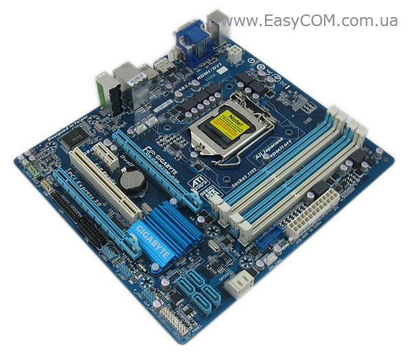
Материнская плата GA-H77M-D3H от компании GIGABYTE основана на новом наборе системной логики Intel H77 Express (более подробно с основными характеристиками чипсета Intel H77 Express, а также его отличиями от «старшего» Intel Z77 Express мы ознакомились ранее) и рассчитана на установку процессоров Intel Sandy Bridge или лучше Intel Ivy Bridge, установка которых обеспечит работу слота расширения PCI-Express х16 по стандарту 3.0.
Стоит отметить, что в линейке MicroATX решений от GIGABYTE, основанных на чипсете Intel H77 Express, рассматриваемая плата является пока единственной моделью.
Ее «старшим» братом можно назвать плату GIGABYTE GA-H77-DS3H, основными отличиями которой являются другой формат (ATX), большее количество слотов расширения, наличие порта mSATA, а также отсутствие устаревшего порта LPT (в GIGABYTE GA-H77M-D3H он присутствует).
Предлагаем перейти непосредственно к обзору материнской платы GIGABYTE GA-H77M-D3H.
Спецификации материнской платы GIGABYTE GA-H77M-D3H:
|
Производитель |
GIGABYTE |
|
Модель |
GA-H77M-D3H (rev 1.0) |
|
Чипсет |
Intel H77 Express |
|
Процессорный разъем |
Socket LGA 1155 |
|
Поддерживаемые процессоры |
Intel Core i7/ Core i5 / Core i3 второго и третьего поколения |
|
Используемая память |
1600/1333/1066 МГц |
|
Поддержка памяти |
4 x 1.5V DDR3 DIMM слота с поддержкой до 32 ГБ памяти |
|
Слоты расширения |
1 x PCI Express 16 3.0 (x16) |
|
Дисковая подсистема |
Чипсет Intel H77 Express поддерживает: |
|
LAN |
1 x гигабитный сетевой контроллер Atheros AR8151 (10/100/1000 Мбит/с) |
|
Звуковая подсистема |
Кодек VIA VT2021 |
|
Питание |
24-контактный разъем питания ATX |
|
Охлаждение |
Алюминиевый радиатор чипсета |
|
Внешние порты I/O |
1 x HDMI |
|
Внутренние порты I/O |
1 x USB 3.0 с поддержкой подключения двух USB 3.0 (19-пин) |
|
BIOS |
2 x 64 Мбит ПЗУ |
|
Комплектация |
руководство пользователя; |
|
Форм-фактор, |
MicroATX |
|
Сайт производителя |
http://www.gigabyte.ua/ |
Упаковка и комплектация
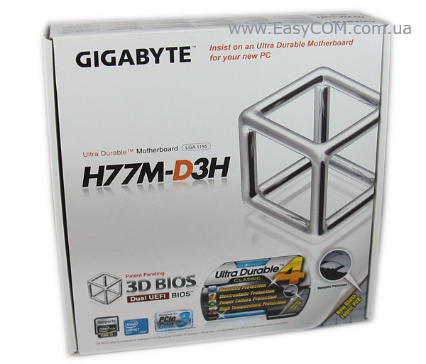
Стандартно для GIGBYTE, материнские платы, основанные на новом поколении чипсетов, поставляются в компактной картонной коробке, выполненной из белого глянцевого картона. Общее оформление упаковки выполнено в сдержанном стиле. В отличие от упаковок предыдущего поколения материнских плат, преобладают серый и черный цвета. На лицевой стороне коробки производитель перечислил некоторые ключевые спецификации решения и поддерживаемые им фирменные технологии. Особое внимание обращено на поддержку платой функций GIGABYTE 3D BIOS на базе фирменной технологии GIGABYTE UEFI DualBIOS и 3D POWER. Также производитель отметил поддержку платой фирменной концепции Ultra Durable 4, которая подразумевает применение качественной элементной базы в процессе производства и дополнительную защиту платы от повышенной влажности, перепадов напряжения в процессе обновления версии прошивки, а также статического напряжения и высоких температур. Отдельно отмечена готовность платы к работе с новыми процессорами семейства Intel Ivy Bridge, выполненными по 22-нанометровому процессу, и поддержка PCI-Express 3.0.
Исходя из названия платы, заранее становится понятно, какими именно отличительными особенностями она обладает. Давайте разберемся в маркировке платы GA-H77M-D3H:
-
GA — изделие компании GIGABYTE: категория «Системные платы»;
-
H77 — название использованного в материнской плате чипсета;
-
M — обозначение форм-фактора, а именно Micro-ATX;
-
D — на плате установлены только твёрдотельные конденсаторы;
-
3 — сегмент (от 2 до 9), в данном случае бюджетный;
-
H — расширенные возможности для вывода видеосигнала средствами интегрированного в ядро ЦП графического контроллера (несколько различных видеопортов, в т.ч. HDMI).
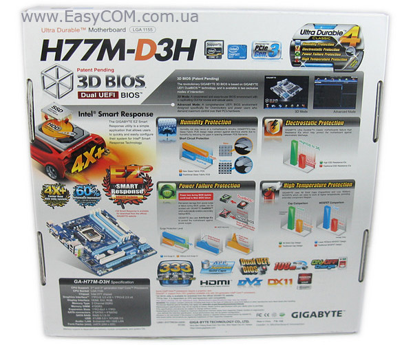
На обратной стороне упаковки детально описаны основные технологии, примененные в материнской плате, а также ее ключевые особенности. В центральной части упаковки расположено детальное описание фирменной концепции Ultra Durable 4.
В нижней части нанесены логотипы использованных технологий, а именно:
-
Поддержка в BIOS накопителей объемом свыше 3 ТБ;
-
Поддержка USB 3.0, SATA 3.0, 3x USB Power Boost (концепция 333);
-
Наличие DVI и HDMI выходов;
-
Поддержка технологии ATI CrossFireX;
-
GIGABYTE On/Off Charge – зарядка портативных устройств даже при выключенном компьютере;
-
Intel Smart Response Technology – данная технология позволяет пользователям самостоятельно создать гибридный жесткий диск (пространство твердотельного накопителя (SSD) можно использовать в качестве кэша для традиционного жесткого диска (или RAID-массива), тем самым получая скорость SSD при работе с часто используемыми файлами и преимущества жесткого диска – его большой объем).
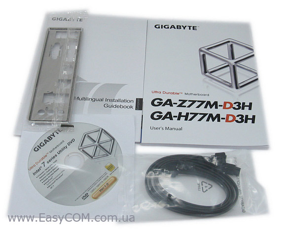
Комплект поставки очень скромный, все во имя снижения конечной стоимости материнской платы для потребителя. В комплекте с GIGABYTE GA-H77M-D3H поставляется:
-
Документация;
-
Диск с драйверами и утилитами;
-
Два SATA-шлейфа (один из них с Г-образным коннектором);
-
Заглушка интерфейсной панели.
Дизайн и особенности платы
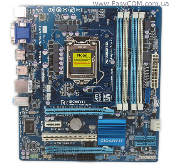
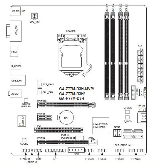
Дизайн материнской платы GIGABYTE GA-H77M-D3H типичный для Micro-ATX моделей компании. Компоновка платы выполнена достаточно продуманно, но присутствуют и стандартные, для решений подобного размера, недостатки, а именно: нижние защелки разъемов для установки модулей памяти близко соседствуют со слотом PCI Express x16, что затруднит доступ к модулям при установленной видеокарте. На нижнем правом краю платы отсутствует крепежное отверстие под винт, что требует определенной аккуратности при подключении SATA устройств. Однако фактически все порты и разъемы размещены по краю платы, что будет удобно при размещении проводов и кабелей в системном блоке.
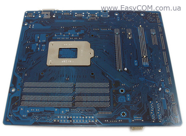
Обратная сторона привлекает внимание разве что усилительной пластиной разъема Socket LGA1155 производства Lotes, что должно обеспечить возможность установки достаточно мощных систем охлаждения.
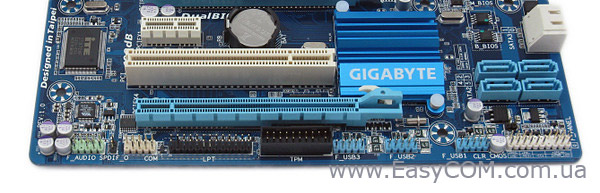
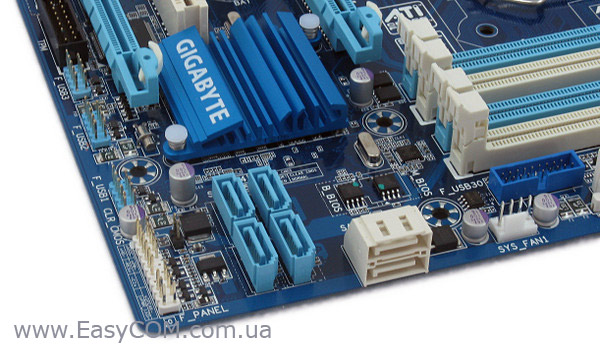
В нижней части материнской платы расположены шесть портов SATA, правда странно, что производитель расположил два порта параллельно, а остальные четыре – перпендикулярно текстолиту. Все они реализованы силами чипсета Intel H77 Express. Четыре порта синего цвета соответствуют спецификации SATA 3 Гбит/с, два порта белого — SATA 6 Гбит/с. Присутствует поддержка массивов SATA RAID 0, RAID 1, RAID 5 и RAID 10. Порты расположены на достаточном отдалении от PCI Express слотов, и соответственно даже длинные видеокарты не затруднят подключение накопителей. Рядом расположены три колодки подключения внутренних портов USB 2.0, передней панели, джампер Clr_CMOS, колодка подключения аудио разъемов фронтальной панели, порты LPT и COM, а также разъем под Trusted Platform Module (TPM).
На правой стороне материнской платы кроме SATA-портов расположена колодка подключения выносной панели с двумя портами USB 3.0 (в комплекте не поставляется). Можно отметить очень удобное ее расположение, при подключении не придется протягивать провода по всему системному блоку.
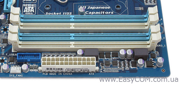
Системная плата GIGABYTE GA-H77M-D3H оснащена четырьмя DIMM-слотами для установки модулей оперативной памяти стандарта DDR3, которые оборудованы защелками с обеих сторон. Оперативная память может работать в двухканальном режиме, для его реализации модули необходимо устанавливать либо в два белых, либо в два синих слота. Поддерживаются модули работающие на частотах 1600/1333/1066 МГц в номинальном режиме. Что интересно, работа памяти на частоте 1600 МГц возможна только при установленном процессоре от Intel третьего поколения. Максимальный объем памяти может составлять 32 ГБ, чего должно быть достаточно в большинстве случаев.
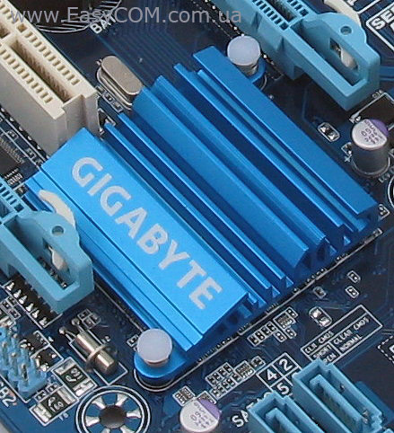
Система охлаждения рассматриваемой платы состоит одного алюминиевого радиатора, который осуществляет отвод тепла от чипсета Intel H77 Express. Крепится радиатор при помощи пластиковых клипс на пружинках. В процессе тестирования температура радиатора не превышала 43°C, что является неплохим результатом для материнских плат, основанных на чипсете Intel H 77 Express, с достаточно скромной системой охлаждения.
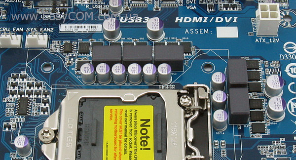
К сожалению, производитель не оснастил дополнительным охлаждением силовые элементы платы. Хотя, учитывая отсутствие возможностей для существенного оверклокинга, такой шаг вполне закономерен.
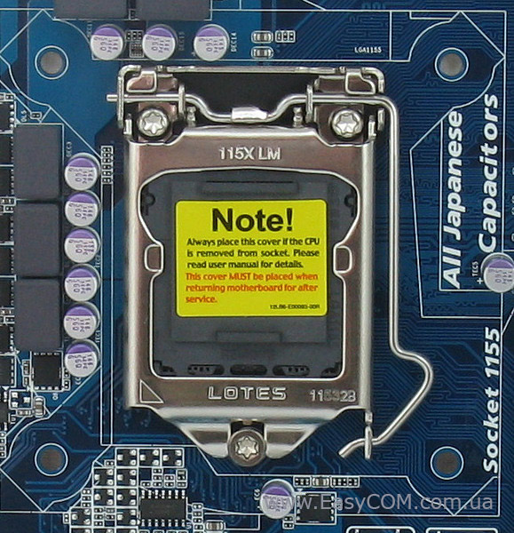
Расположение Socket LGA1155 и опорной пластины стандартно. Питание процессора осуществляется по 3+1+1-фазной схеме для вычислительных ядер и дополнительных узлов. Сам преобразователь основан на ШИМ-контроллере ISL95836, который поддерживает активное переключение фаз питания для повышения уровня КПД.
Для питания GIGABYTE GA-H77M-D3H предназначены стандартные для устройства такого класса основной 24-х и дополнительный 4-контактный разъемы.
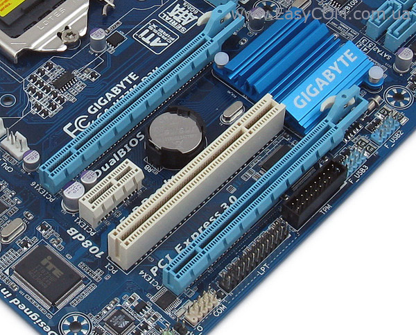
Возможности расширения функциональности материнской платы GIGABYTE GA-H77M-D3H соответствуют стоимости и классу продукта, а также характерны для решений выполненных в форм-факторе Micro-ATX. В наличии два слота для установки графических адаптеров — PCI-Express 3.0 х16 и PCI-Express 2.0 х16 (х4) Производителем заявлена поддержка технологии ATI CrossFireX.
Если у вас один графический адаптер, то его необходимо устанавливать в первый слот, который будет функционировать в режиме х16. Поскольку возможности чипсета Intel H77 Express позволяют выводить изображение со встроенного в процессор видеоядра, то слоты PCI-Express могут быть использованы и для установки иных карт расширения. Также расширение функциональности материнской платы возможно за счет одного слота PCI-Express х1 и одного PCI. Поскольку современные чипсеты Intel, в том числе и Intel H77 Express, не поддерживают устаревшую шину PCI, то функционирование слота, расположенного на материнской плате, реализуется за счет моста PCIE-PCI, основанного на контроллере ITE IT8892E.
Отдельно стоит отметить, что работа слотов PCI-Express по спецификации 3.0 будет возможна только при наличии процессора семейства Intel Ivy Bridge.
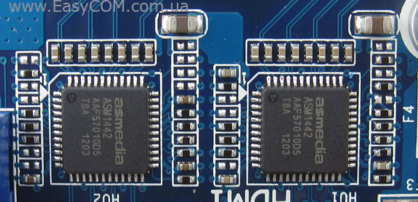
Если вы планируете использовать интегрированную графику, проблем с подключением современных устройств вывода изображения не возникнет, поскольку все необходимые разъёмы присутствуют. Функционирование видеовыходов и переключение между портами VGA, DVI и HDMI интегрированного видео осуществляется силами двух микросхем ASMedia ASM1442.
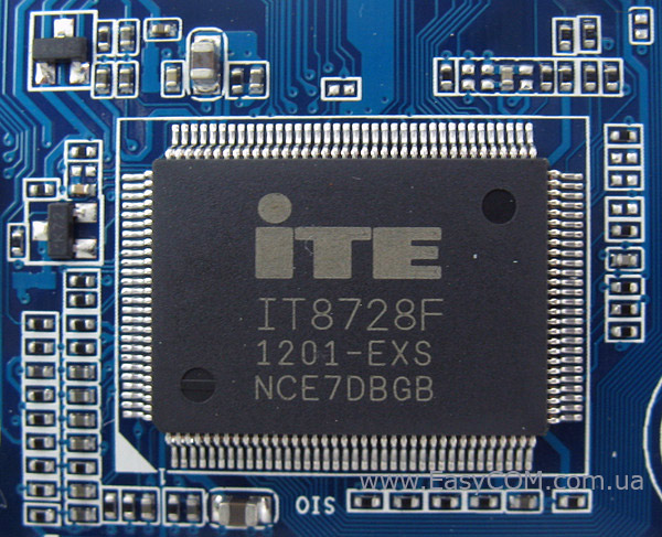
Возможности Multi I/O обеспечены микросхемой ITE IT8728F, которая управляет портами PS/2, работой системных вентиляторов и обеспечивает мониторинг.
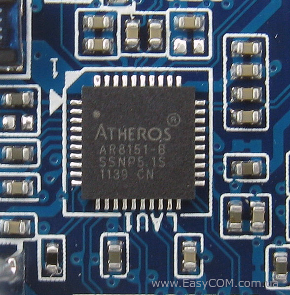
Для поддержки сетевых соединений служит гигабитный LAN-контроллер Atheros AR8151.
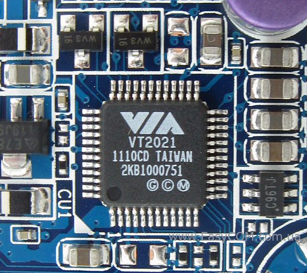
Звуковая подсистема рассматриваемой материнской платы основана на HDA-кодеке 8-канального звука VIA VT2021, который поддерживает аудиосистемы форматов 2/4/5.1/7.1.
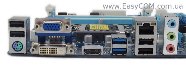
На интерфейсную панель материнской платы GIGABYTE GA-H77M-D3H выведены следующие порты:
- 1 x HDMI;
- 1 x DVI-D;
- 1 x VGA;
- 1 x LAN (RJ45);
- 2 x USB 3.0;
- 4 x USB 2.0;
- 3 x Аудио порта;
- 1 x PS/2 (мышь/клавиатура).
Как видим, конфигурация внешних портов вполне достаточна для комфортного использования системы, огорчает разве что отсутствие eSATA и малое количество USB 3.0, но назвать это недостатком платы нельзя. К недостаткам же можно отнести наличие всего трех аудио портов, при наличии поддержки восьмиканального звука, что выглядит достаточно спорным решением. Впрочем, многоканальную аудиосистему подключить можно, задействовав и выходы фронтальной аудиопанели, но это будет очень неудобно.
Материнская плата GIGABYTE GA-H77M-D3H оснащена тремя разъемами для подключения вентиляторов, один из которых выполнен в четырехконтактном исполнении для подключения вентилятора системы охлаждения процессора, а два других предназначены для подключения системных вентиляторов.
BIOS

Материнская плата GIGABYTE GA-H77M-D3H оснащена современной прошивкой UEFI на основе микрокода AMI с приятным графическим интерфейсом, возможностью управления с помощью мышки и поддержкой накопителей объёмом больше 3 ТБ. К тому же отметим, что плата оснащена двумя микросхемами BIOS (технология DualBIOS), что позволит сохранить работоспособность системы в случае повреждения основной микросхемы с прошивкой.
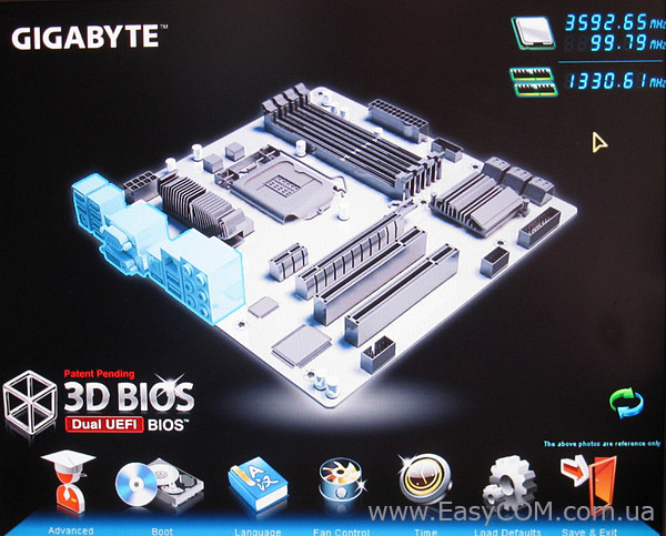
Само меню разделено на два отдельных режима работы, первый из них – 3D BIOS. При наведении указателя «мышки» на один из компонентов материнской платы открывается список параметров, доступных для изменения, относящихся к данному компоненту платы.
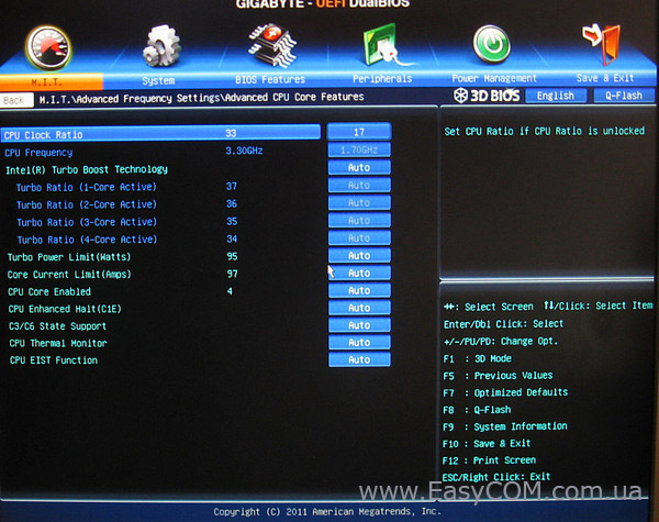
Основная часть настроек, касающихся изменения частоты работы тактового генератора (BCLK), CPU, встроенного графического ядра, оперативной памяти сгруппированы в разделе MB Intelligent Tweaker (M.I.T.), где в свою очередь они удобно разнесены по подразделам, в зависимости от типа.
Настройки, необходимые для разгона, сведены в таблицу:
|
Параметр |
Название меню |
Диапазон |
Шаг |
|
Частота системной шины, МГц |
CPU/PCIe Base Clock |
80 – 150 |
0,1 |
|
Частота встроенного графического ядра, МГц |
Internal Graphics Clock |
400 – 1600 |
50 |
|
Процессорные технологии |
C1E, C3/C6 State, EIST, CPU Thermal Monitor |
||
|
Процессорный множитель |
CPU Clock Ratio |
17 – 34 |
1 |
|
Ограничение по мощности, Вт |
Turbo Power Limit |
0 – 1200 |
1 |
|
Ограничение по току, А |
Core Current Limit |
0 – 300 |
1 |
|
Делитель для памяти |
System Memory Multipllier |
10.66, 13.33, 16, |
|
|
Задержки ОЗУ |
CAS Latency, tRCD, tRP, tRAS, tRRD, tWTR, tWR, tWTP, tRFC, tRTP, tFAW, tCMD |
||
|
Напряжение на модулях памяти, Вт |
DRAM Voltage (CH A/B) |
1,1 – 2,8 |
0,005 |
В разделе PC Health Status открывается доступ к наблюдению за температурой процессора и чипсета, а также скоростью вращения установленных вентиляторов. Здесь же можно задавать вручную требуемую скорость вращения вентиляторов.
Также не обошлось без отдельного раздела мониторинга, в котором можно следить за:
-
напряжением на ядре процессора;
- напряжением на графическом ядре;
- напряжением на модулях памяти;
- напряжением на линии питания +12В, +5В и +3,3В.
Отдельно стоит отметить возможность снятия «скриншотов» прямо в BIOS и поддержку русского языка.
Тестирование
Для проверки возможностей материнской платы использовалось следующее оборудование:
|
Процессор |
Intel Core i5-2500K (LGA1155, 3,3 ГГц, L3 6 МБ) |
|
Кулер |
Scythe Kama Angle Rev.B |
|
Оперативная память |
2x DDR3-2000 1024 МБ Kingston HyperX KHX16000D3T1K3/3GX |
|
Видеокарта |
MSI R4850-2D1G-OC (Radeon HD 4850, 1 ГБ GDDR3, PCIe 2.0) |
|
Жесткий диск |
Seagate Barracuda 7200.12 ST3500418AS, 500 ГБ, SATA-300, NCQ |
|
Оптический привод |
ASUS DRW-1814BLT SATA |
|
Блок питания |
Seasonic SS-650JT Active PFC (650 Вт, 120 мм вентилятор) |
|
Корпус |
CODEGEN M603 MidiTower (2х 120 мм вентилятора на вдув/выдув) |
Результаты тестов:
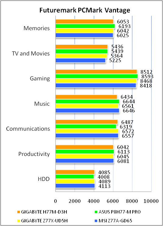
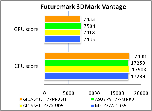
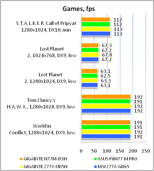
В процессе тестирования GIGABYTE GA-H77M-D3H показала производительность на уровне с конкурентами. В целом, исходя из результатов тестирования, можно сделать вывод о качественном уровне исполнения платы и хорошей оптимизации BIOS. Также, как видно по результатам тестирования, чипсет Intel H77 Express не уступает в производительности «старшему» Intel Z77 Express.
Тестирование звукового тракта на основе кодека VIA VT2021
Отчет о тестировании в RightMark Audio Analyzer
16-bit, 44,1 kHz
|
Неравномерность АЧХ (в диапазоне 40 Гц — 15 кГц), дБ |
+0.14, -0.20 |
Очень хорошо |
|
Уровень шума, дБ (А) |
-87.1 |
Хорошо |
|
Динамические диапазон, дБ (А) |
86.9 |
Хорошо |
|
Гармонические искажения, % |
0.0050 |
Очень хорошо |
|
Гармонические искажения + шум, дБ(A) |
-65.9 |
Средне |
|
Интермодуляционные искажения + шум, % |
0.067 |
Хорошо |
|
Взаимопроникновение каналов, дБ |
-85.1 |
Отлично |
|
Интермодуляции на 10 кГц, % |
0.049 |
Хорошо |
|
Общая оценка |
Хорошо |
Режим работы 24-bit, 192 kHz
|
Неравномерность АЧХ (в диапазоне 40 Гц — 15 кГц), дБ |
+0.12, -0.20 |
Очень хорошо |
|
Уровень шума, дБ (А) |
-88.2 |
Хорошо |
|
Динамические диапазон, дБ (А) |
88.0 |
Хорошо |
|
Гармонические искажения, % |
0.0039 |
Очень хорошо |
|
Гармонические искажения + шум, дБ(A) |
-80.6 |
Хорошо |
|
Интермодуляционные искажения + шум, % |
0.013 |
Очень хорошо |
|
Взаимопроникновение каналов, дБ |
-82.3 |
Очень хорошо |
|
Интермодуляции на 10 кГц, % |
0.018 |
Очень хорошо |
|
Общая оценка |
Хорошо |
Встроенный 8-канальный звуковой кодек продемонстрировал довольно хорошие результаты, и его будет достаточно подавляющему большинству пользователей для повседневной работы, прослушивания музыки, обеспечения звукового сопровождения к фильмам и играм при домашнем использовании. Вот только наличие всего трех аналоговых аудио выходов на интерфейсной панели не располагает к использованию многоканальных аудио систем.
Выводы
Рассмотренное сегодня решение от GIGABYTE для сборки компактных, но вместе с тем производительных компьютеров, обладает рядом как положительных, так и отрицательных особенностей. Прежде чем перейти непосредственно к выводам напомним читателю, что стоимость данного решения колеблется в пределах 100 долл. США.
Из достоинств платы стоит отметить общую функциональность и производительность на фоне небольшого размера, возможность установки двух дискретных видеоадаптеров, наличие современных портов USB 3.0. и SATA 6 Гбит/с.
К отличительным особенностям платы, безусловно, можно отнести использование надежной элементной базы, использование двух микросхем с прошивками BIOS, что позволит вам избежать проблем с неудачным обновлением. Также к преимуществам платы можно отнести наличие интересной технологии 3D BIOS. Возможно, некоторых покупателей заинтересует наличие уже устаревших, но все еще используемых пользователями портов COM и LPT.
Из недостатков GIGABYTE GA-H77M-D3H можно отметить скромную комплектацию, а так же тот факт, что потенциальным покупателям рассмотренного нами решения, которые являются владельцами аудиосистем формата 5.1 или 7.1, будет очень непросто их задействовать. Кроме того, кому-то может показаться критичным отсутствие портов eSATA и DisplayPort.
В итоге, нам кажется, что GIGABYTE GA-H77M-D3H может найти своего покупателя при условии снижения стоимости, ведь при наличии дополнительных 20 долл. США намного более разумным кажется приобретение GIGABYTE GA-Z77MX-D3H.
Достоинства:
-
качественная элементная база;
-
поддержка USB 3.0 и наличие портов SATA 6 Гбит/с;
-
наличие цифровых видеовыходов;
-
функции DualBIOS и 3D BIOS;
-
поддержка интерфейсов COM и LPT.
Недостатки:
-
очень скромный комплект поставки;
-
отсутствие портов eSATA и DisplayPort;
-
завышенная стоимость;
-
наличие только трех аналоговых аудиовыходов на интерфейсной панели.
Особенности:
-
поддержка технологии AMD CrossFireX;
-
«провисание» верхнего и нижнего углов правого края потребует аккуратности при сборке;
-
отсутствует поддержка устаревших интерфейсов FDD и IDE.

Автор: Константин Шорохов
Выражаем благодарность украинскому представительству компании GIGABYTE за предоставленную для тестирования материнскую плату.
Выражаем благодарность компаниям Intel, Kingston, MSI и SeaSonic за предоставленное для тестового стенда оборудование.