-
Драйверы
31
-
Инструкции по эксплуатации
18
Языки:

Gigabyte GA-H77M-D3H инструкция по эксплуатации
(72 страницы)
- Языки:Венгерский, Греческий, Испанский, Итальянский, Немецкий, Польский, Португальский, Русский, Турецкий, Французский, Чешский
-
Тип:
PDF -
Размер:
18.6 MB -
Описание:
Installation Guidebook


На NoDevice можно скачать инструкцию по эксплуатации для Gigabyte GA-H77M-D3H. Руководство пользователя необходимо для ознакомления с правилами установки и эксплуатации Gigabyte GA-H77M-D3H. Инструкции по использованию помогут правильно настроить Gigabyte GA-H77M-D3H, исправить ошибки и выявить неполадки.
Посмотреть инструкция для Gigabyte GA-H77M-D3H бесплатно. Руководство относится к категории Материнские платы, 1 человек(а) дали ему среднюю оценку 7.5. Руководство доступно на следующих языках: английский. У вас есть вопрос о Gigabyte GA-H77M-D3H или вам нужна помощь? Задайте свой вопрос здесь
Не можете найти ответ на свой вопрос в руководстве? Вы можете найти ответ на свой вопрос ниже, в разделе часто задаваемых вопросов о Gigabyte GA-H77M-D3H.
Какая ширина Gigabyte GA-H77M-D3H?
Какая толщина Gigabyte GA-H77M-D3H?
Инструкция Gigabyte GA-H77M-D3H доступно в русский?
Не нашли свой вопрос? Задайте свой вопрос здесь
4 июля 2013 г.
- Производитель
- Gigabyte
- Модель
- GA-H77M-D3H
- Операционная система
-
- Неизвестная ОС
- Тип файла
-
- Инструкция
- Версия
-
1201
32-bit
Просмотреть содержимое архива
Вы нашли то, что искали?
Изображения

‹
›
×
Полезно
0 %
0
Commentary
Ваше имя
-
Contents
-
Table of Contents
-
Troubleshooting
-
Bookmarks
GA-Z77M-D3H-MVP/GA-Z77M-D3H/GA-H77M-D3H
Motherboard Layout
KB_MS_USB
ATX_12V
HDMI
R_USB30
USB_LAN
SYS_FAN2
CPU_FAN
AUDIO
PCIEX16
Atheros
GbE LAN
PCIEX1
PCI
PCIEX4
CODEC
F_AUDIO
COM
SPDIF_O
Only for GA-Z77M-D3H-MVP.
M
Only for GA-Z77M-D3H.
N
Only for GA-H77M-D3H.
O
LGA1155
GA-Z77M-D3H-MVP/
GA-Z77M-D3H/
GA-H77M-D3H
BAT
PCIe to
PCI Bridge
TPM
LPT
F_USB3
— 7 —
M_BIOS
B_BIOS
Intel
Z77MN
®
Intel
H77O
SATA2
®
2 3
4 5
CLR_CMOS
F_USB2
F_USB1
F_PANEL
ATX
SATA3
1 0
Related Manuals for Gigabyte GA-Z77M-D3H
Related Content for Gigabyte GA-Z77M-D3H
Table of Contents
 Loading…
![]()
GA-Z77M-D3H-MVP GA-Z77M-D3H GA-H77M-D3H
User’s Manual
Rev. 1003
12ME-H77MD3H-1003R
|
Declaration of Conformity |
|
|
We, Manufacturer/Importer, |
|
|
G.B.T. Technology Trading GMbH |
|
|
ddress:A |
Bullenkoppel 16, 22047 Hamburg, Germany |
|
Declare that the product |
|
|
Product Type: |
Motherboard |
|
Product Name: |
GA-Z77M-D3H-MVP/GA-Z77M-D3H/GA-H77M-D3H |
conforms with the essential requirements of the following directives:
 2004/108/EC EMC Directive:
|
Conduction & Radiated Emissions: |
EN55022:2006+A1:2007 |
|||
|
Immunity: |
EN55024:1998+A1:2001+A2:2003 |
|||
|
EN61000-3-2:2006 |
||||
|
Power-line harmonics: |
||||
|
Power-line flicker: |
EN61000-3-3:2008 |
|||
|
2006/95/EC LVD Directive |
||||
|
: |
Safety |
EN60950-1:2006+A11:2009 |
||
|
2011/65/EU RoHS Directive |
||||
|
Restriction of use of certain |
This product does not contain any of the restricted |
|||
|
substances in electronic equipment: |
substances listed in Annex II, in concentrations |
|||
|
and applications banned by the directive. |
||||
|
CE marking |
||||
|
(EC conformity marking) |
||||
|
Signature: |
Timmy Huang |
|||
|
(Stamp) |
Date: Jan. 31, 2012 |
Name: |
Timmy Huang |
|
Motherboard
GA-Z77M-D3H-MVP GA-Z77M-D3H GA-H77M-D3H
Jan. 31, 2012
Copyright
© 2012 GIGA-BYTE TECHNOLOGY CO., LTD. All rights reserved.
The trademarks mentioned in this manual are legally registered to their respective owners.
Disclaimer
Information in this manual is protected by copyright laws and is the property of GIGABYTE.
Changes to the specifications and features in this manual may be made by GIGABYTE without prior notice.
No part of this manual may be reproduced, copied, translated, transmitted, orpublished in any form or by any means without GIGABYTE’s prior written permission.
Documentation Classifications
In order to assist in the use of this product, GIGABYTE provides the following types of
documentations:
For quick set-up of the product, read the Quick Installation Guide included with the product.For detailed product information, carefully read the User’s Manual.
For product-related information, check on our website at: http://www.gigabyte.com
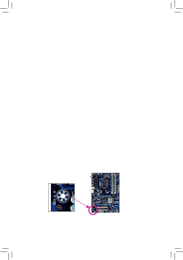
Identifying Your Motherboard Revision
The revision number on your motherboard looks like this: «REV: X.X.» For example, «REV: 1.0» means the revision of the motherboard is 1.0. Check your motherboard revision before updating motherboard BIOS, drivers, or when looking for technical information.
Example:

Table of Contents
|
Box Contents…………………………………………………………………………………………………….. |
6 |
||
|
Optional Items…………………………………………………………………………………………………… |
6 |
||
|
GA-Z77M-D3H-MVP/GA-Z77M-D3H/GA-H77M-D3H Motherboard Layout………………… |
7 |
||
|
GA-Z77M-D3H-MVP/GA-Z77M-D3H/GA-H77M-D3H Motherboard Block Diagram…….. |
8 |
||
|
Chapter 1 Hardware Installation………………………………………………………………………….. |
9 |
||
|
1-1 |
Installation Precautions…………………………………………………………………………. |
9 |
|
|
1-2 |
Product Specifications………………………………………………………………………… |
10 |
|
|
1-3 Installing the CPU and CPU Cooler………………………………………………………. |
13 |
||
|
1-3-1 |
Installing the CPU……………………………………………………………………………………… |
13 |
|
|
1-3-2 Installing the CPU Cooler……………………………………………………………………………. |
15 |
||
|
1-4 |
Installing the Memory………………………………………………………………………….. |
16 |
|
|
1-4-1 Dual Channel Memory Configuration………………………………………………………………… |
16 |
||
|
1-4-2 |
Installing a Memory……………………………………………………………………………………. |
17 |
|
|
1-5 Installing an Expansion Card……………………………………………………………….. |
18 |
||
|
1-6 |
Back Panel Connectors………………………………………………………………………. |
19 |
|
|
1-7 |
Internal Connectors……………………………………………………………………………. |
21 |
|
|
Chapter 2 BIOS Setup……………………………………………………………………………………… |
31 |
||
|
2-1 |
Startup Screen…………………………………………………………………………………… |
32 |
|
|
2-2 |
The Main Menu………………………………………………………………………………….. |
33 |
|
|
2-3 |
M.I.T…………………………………………………………………………………………………. |
35 |
|
|
2-4 |
System……………………………………………………………………………………………… |
43 |
|
|
2-5 |
BIOS Features…………………………………………………………………………………… |
44 |
|
|
2-6 |
Peripherals………………………………………………………………………………………… |
46 |
|
|
2-7 |
Power Management……………………………………………………………………………. |
50 |
|
|
2-8 |
Save & Exit……………………………………………………………………………………….. |
52 |
— 4 —

|
Chapter 3 Drivers Installation……………………………………………………………………………. |
53 |
|
|
3-1 |
Installing Chipset Drivers…………………………………………………………………….. |
53 |
|
3-2 |
Application Software…………………………………………………………………………… |
54 |
|
3-3 |
Technical Manuals……………………………………………………………………………… |
54 |
|
3-4 |
Contact…………………………………………………………………………………………….. |
55 |
|
3-5 |
System……………………………………………………………………………………………… |
55 |
|
3-6 |
Download Center……………………………………………………………………………….. |
56 |
|
3-7 |
New Program…………………………………………………………………………………….. |
56 |
|
Chapter 4 Unique Features………………………………………………………………………………. |
57 |
||
|
4-1 |
Xpress Recovery2……………………………………………………………………………… |
57 |
|
|
4-2 |
BIOS Update Utilities………………………………………………………………………….. |
60 |
|
|
4-2-1 Updating the BIOS with the Q-Flash Utility……………………………………………………. |
60 |
||
|
4-2-2 Updating the BIOS with the @BIOS Utility…………………………………………………….. |
63 |
||
|
4-3 |
EasyTune 6……………………………………………………………………………………….. |
64 |
|
|
4-4 |
Q-Share……………………………………………………………………………………………. |
65 |
|
|
4-5 |
eXtreme Hard Drive (X.H.D)………………………………………………………………… |
66 |
|
|
4-6 |
Auto Green……………………………………………………………………………………….. |
67 |
|
|
4-7 |
Intel Rapid Start Technology………………………………………………………………… |
68 |
|
|
4-8 |
Intel Smart Connect Technology…………………………………………………………… |
70 |
|
|
4-9 |
Intel Smart Response…………………………………………………………………………. |
72 |
|
Chapter 5 Appendix |
…………………………………………………………………………………………. |
75 |
|
|
5-1 |
Configuring SATA Hard Drive(s)…………………………………………………………… |
75 |
|
|
5-1-1 |
Configuring SATA Controllers ………………………………………………………………………. |
75 |
|
|
5-1-2 Installing the SATA RAID/AHCI Driver and Operating System………………………….. |
83 |
||
|
5-2 |
Configuring ……………………………………………………….Audio Input and Output |
88 |
|
|
5-2-1 …………………………………………………………. |
Configuring 2/4/5.1/7.1 — Channel Audio |
88 |
|
|
5-2-2 ……………………………………………………………………………… |
Configuring S/PDIF Out |
90 |
|
|
5-2-3 ………………………………………………………………. |
Configuring Microphone Recording |
91 |
|
|
5-2-4 …………………………………………………………………………..Using the Sound Recorder |
93 |
||
|
5-3 |
Troubleshooting…………………………………………………………………………………. |
94 |
|
|
5-3-1 ………………………………………………………………………. |
Frequently Asked Questions |
94 |
|
|
5-3-2 …………………………………………………………………………. |
Troubleshooting Procedure |
95 |
|
|
5-3-3 ……………………………………………………………………………….. |
Regulatory Statements |
97 |
|
|
— 5 — |
Box Contents
55 GA-Z77M-D3H-MVP, GA-Z77M-D3H or GA-H77M-D3H motherboard 55 Motherboard driver disk
55 User’s Manual
55 Quick Installation Guide
55 Two SATA 6Gb/s cables
55 I/O Shield
The box contents above are for reference only and the actual items shall depend on the product package you obtain. The box contents are subject to change without notice.
Optional Items
2-port USB 2.0 bracket (Part No. 12CR1-1UB030-5*R)2-port SATA power cable (Part No. 12CF1-2SERPW-0*R)
3.5″ Front Panel with 2 USB 3.0/2.0 ports (Part No. 12CR1-FPX582-0*R)COM port cable (Part No. 12CF1-1CM001-3*R)
LPT port cable (Part No. 12CF1-1LP001-0*R)
— 6 —
GA-Z77M-D3H-MVP/GA-Z77M-D3H/GA-H77M-D3H
Motherboard Layout
|
KB_MS_USB |
|
|
ATX_12V |
|
|
VGA DVI |
|
|
HDMI |
|
|
R_USB30 |
|
|
USB_LAN |
|
|
SYS_FAN2 |
|
|
AUDIO |
CPU_FAN |
|
Atheros |
PCIEX16 |
|
GbE LAN |
|
|
PCIEX1 |
LGA1155
GA-Z77M-D3H-MVP/ GA-Z77M-D3H/ GA-H77M-D3H
|
DDR3 4 |
DDR3 2 |
DDR3 3 DDR3 1 |
ATX
|
F USB30 |
SYS FAN1 |
||
|
M_BIOS |
SATA3 |
||
|
1 |
0 |
||
iTE Super I/O
|
BAT |
B_BIOS |
||
|
Intel® Z77jk |
|||
|
PCI |
|||
|
Intel® H77• |
SATA2 |
||
|
PCIe to |
2 |
3 |
||||
|
4 |
5 |
|||||
|
PCIEX4 |
PCI Bridge |
|||||
|
CODEC |
CLR_CMOS |
|||||
|
TPM |
||||||
|
F_AUDIO |
COM |
LPT |
F_USB3 F_USB2 |
F_USB1 |
F_PANEL |
|
|
SPDIF_O |
MM Only for GA-Z77M-D3H-MVP. NN Only for GA-Z77M-D3H.
OO Only for GA-H77M-D3H.
— 7 —
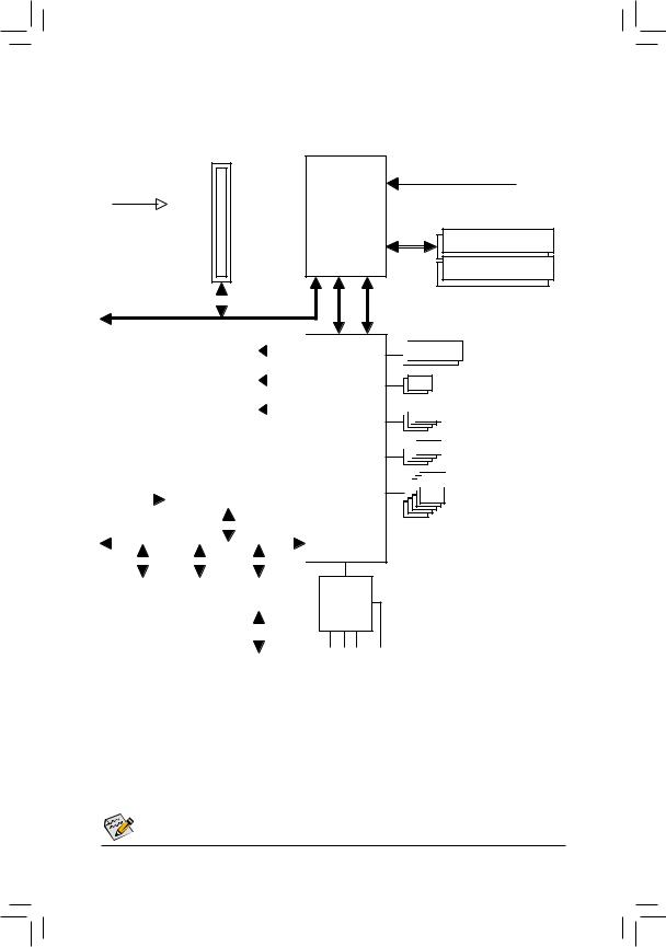
GA-Z77M-D3H-MVP/GA-Z77M-D3H/GA-H77M-D3H
Motherboard Block Diagram
1 PCI Express x16
PCIe CLK
(100 MHz)
|
PCI Express Bus |
x16 |
|||||||||||||||||||||||||||
|
D-Sub |
||||||||||||||||||||||||||||
|
DVI-D |
||||||||||||||||||||||||||||
|
HDMI |
||||||||||||||||||||||||||||
|
LAN |
||||||||||||||||||||||||||||
|
PCIe CLK |
RJ45 |
|||||||||||||||||||||||||||
|
(100 MHz) |
Atheros |
|||||||||||||||||||||||||||
|
GbE LAN |
||||||||||||||||||||||||||||
|
PCI Express Bus |
x1 |
|||||||||||||||||||||||||||
|
x1 |
x4 |
x1 |
||||||||||||||||||||||||||
|
PCIe to |
||||||||||||||||||||||||||||
|
PCI Bridge |
||||||||||||||||||||||||||||
|
PCI Bus |
||||||||||||||||||||||||||||
|
1 PCI Express x1 |
||||||||||||||||||||||||||||
|
1 PCI Express x4 |
||||||||||||||||||||||||||||
1 PCI
MM Only for GA-Z77M-D3H-MVP.
NN Only for GA-Z77M-D3H.
OO Only for GA-H77M-D3H.
LGA1155
CPU
FDI
DMI 2.0
Intel® Z77 jk
Intel® H77 •
CODEC
CPU CLK+/- (100 MHz)
DDR3 1600/1333/1066 MHz
Dual Channel Memory

 Dual BIOS
2 SATA 6Gb/s


 4 SATA 3Gb/s


 4 USB 3.0/2.0


 10 USB 2.0/1.1
|
LPC |
iTE |
LPT |
||||
|
Bus |
||||||
|
Super |
COM |
|||||
|
I/O |
||||||
|
PS/2 KB/Mouse |
|
Speaker Out) |
Speaker Out) Speaker Out) S/PDIF Out |
|
(Center/Subwoofer |
Line |
|
(Rear |
|
|
(Front |
|
|
In |
|
|
Out |
|
|
Line |
|
|
MIC |
For detailed product information/limitation(s), refer to “1-2 Product Specifications.”
— 8 —

Chapter 1 Hardware Installation
1-1 Installation Precautions
The motherboard contains numerous delicate electronic circuits and components which can become damaged as a result of electrostatic discharge (ESD). Prior to installation, carefully read the user’s manual and follow these procedures:
•• Prior to installation, make sure the chassis is suitable for the motherboard.
•• Prior to installation, do not remove or break motherboard S/N (Serial Number) sticker or warranty sticker provided by your dealer. These stickers are required for warranty validation.
•• Always remove the AC power by unplugging the power cord from the power outlet before installing or removing the motherboard or other hardware components.
•• When connecting hardware components to the internal connectors on the motherboard, make sure they are connected tightly and securely.
•• When handling the motherboard, avoid touching any metal leads or connectors.
•• It is best to wear an electrostatic discharge (ESD) wrist strap when handling electronic components such as a motherboard, CPU or memory. If you do not have an ESD wrist strap, keep your hands dry and first touch a metal object to eliminate static electricity.
•• Prior to installing the motherboard, please have it on top of an antistatic pad or within an electrostatic shielding container.
•• Before unplugging the power supply cable from the motherboard, make sure the power supply has been turned off.
•• Before turning on the power, make sure the power supply voltage has been set according to the local voltage standard.
•• Before using the product, please verify that all cables and power connectors of your hardware components are connected.
•• To prevent damage to the motherboard, do not allow screws to come in contact with the motherboard circuit or its components.
•• Make sure there are no leftover screws or metal components placed on the motherboard or within the computer casing.
•• Do not place the computer system on an uneven surface.
•• Do not place the computer system in a high-temperature environment.
•• Turning on the computer power during the installation process can lead to damage to system components as well as physical harm to the user.
•• If you are uncertain about any installation steps or have a problem related to the use of the product, please consult a certified computer technician.
|
— 9 — |
Hardware Installation |
|
1-2 |
Product Specifications |
|
|
CPU |
Support for Intel® Core™ i7 processors/Intel® Core™ i5 processors/ |
|
|
Intel® Core™ i3 processors/Intel® Pentium® processors/Intel® Celeron® processors |
||
|
in the LGA1155 package |
||
|
(Go to GIGABYTE’s website for the latest CPU support list.) |
||
|
L3 cache varies with CPU |
||
|
Chipset |
Intel® Z77jk/Intel® H77• Express Chipset |
|
|
Memory |
4 x 1.5V DDR3 DIMM sockets supporting up to 32 GB of system memory |
* Due to Windows 32-bit operating system limitation, when more than 4 GB of physical memory is installed, the actual memory size displayed will be less than 4 GB.
Dual channel memory architecture
Support for DDR3 1600/1333/1066 MHz memory modules
* To support DDR3 1600 MHz, you must install an Intel 22nm (Ivy Bridge) CPU. •
Support for non-ECC memory modules
Support for Extreme Memory Profile (XMP) memory modules
|
* To support XMP memory, you must install an Intel 22nm (Ivy Bridge) CPU. • |
||
|
(Go to GIGABYTE’s website for the latest supported memory speeds and memory |
||
|
modules.) |
||
|
Onboard |
Integrated Graphics Processor: |
|
|
Graphics |
— |
1 x D-Sub port |
|
— |
1 x DVI-D port, supporting a maximum resolution of 1920×1200 |
|
|
* The DVI-D port does not support D-Sub connection by adapter. |
||
|
— |
1 x HDMI port, supporting a maximum resolution of 1920×1200 |
|
Audio |
VIA VT2021 codec |
|
|
High Definition Audio |
||
|
2/4/5.1/7.1-channel |
*To configure 7.1-channel audio, you have to use an HD front panel audio module and enable the multi-channel audio feature through the audio driver.
Support for S/PDIF Out
|
LAN |
Atheros GbE LAN chip (10/100/1000 Mbit) |
|
Expansion Slots |
1 x PCI Express x16 slot, running at x16 (PCIEX16) |
|
(The PCIEX16 slot conforms to PCI Express 3.0 standard.) |
|
|
* For optimum performance, if only one PCI Express graphics card is to be installed, |
|
|
be sure to install it in the PCIEX16 slot. |
|
|
* To support PCI Express 3.0, you must install an Intel 22nm (Ivy Bridge) CPU. |
|
|
1 x PCI Express x16 slot, running at x4 (PCIEX4) |
|
|
1 x PCI Express x1 slot |
|
|
(The PCIEX4 and PCIEX1 slots conform to PCI Express 2.0 standard.) |
|
|
1 x PCI slot |
|
Multi-Graphics |
Support for AMD CrossFireX™ technology |
||
|
Technology |
|||
|
MM |
Only for GA-Z77M-D3H-MVP. |
||
|
NN |
Only for GA-Z77M-D3H. |
||
|
OO |
Only for GA-H77M-D3H. |
||
|
Hardware Installation |
— 10 — |
![]()
|
Storage Interface |
Chipset: |
||
|
— |
2 x SATA 6Gb/s connectors (SATA3 0/1) supporting up to 2 SATA 6Gb/s |
||
|
devices |
|||
|
— |
4 x SATA 3Gb/s connectors (SATA2 2/3/4/5) supporting up to 4 SATA 3Gb/s |
||
|
devices |
|||
|
— |
Support for RAID 0, RAID 1, RAID 5, and RAID 10 |
||
|
* When a RAID set is built across the SATA 6Gb/s and SATA 3Gb/s channels, the |
|||
|
system performance of the RAID set may vary depending on the devices being |
|||
|
connected. |
|||
|
USB |
Chipset: |
||
|
— |
Up to 10 USB 2.0/1.1 ports (4 ports on the back panel, 6 ports available |
||
|
through the internal USB headers) |
|||
|
— |
Up to 4 USB 3.0/2.0 ports (2 ports on the back panel, 2 ports available through |
||
|
the internal USB headers) |
|||
|
* In Windows XP, the Intel USB 3.0 ports can support up to USB 2.0 transfer speed. |
|||
|
Internal |
1 x 24-pin ATX main power connector |
||
|
Connectors |
1 x 4-pin ATX 12V power connector |
||
|
2 x SATA 6Gb/s connectors |
|||
|
4 x SATA 3Gb/s connectors |
|||
|
1 x CPU fan header |
|||
|
2 x system fan headers |
|||
|
1 x front panel header |
|||
|
1 x front panel audio header |
|||
|
1 x S/PDIF Out header |
|||
|
1 x USB 3.0/2.0 header |
|||
|
3 x USB 2.0/1.1 headers |
|||
|
1 x serial port header |
|||
|
1 x parallel port |
|||
|
1 x Trusted Platform Module (TPM) header |
|||
|
1 x Clear CMOS jumper |
|||
|
Back Panel |
1 x PS/2 keyboard/mouse port |
||
|
Connectors |
1 x D-Sub port |
||
|
1 x DVI-D port |
|||
|
1 x HDMI port |
|||
|
2 x USB 3.0/2.0 ports |
|||
|
4 x USB 2.0/1.1 ports |
|||
|
1 x RJ-45 port |
|||
|
3 x audio jacks (Line In/Line Out/Microphone) |
|||
|
I/O Controller |
iTE I/O Controller Chip |
||
|
— 11 — |
Hardware Installation |
|
Hardware |
System voltage detection |
|
|
Monitor |
CPU/System temperature detection |
CPU/System fan speed detectionCPU overheating warning
CPU/System fan fail warningCPU/System fan speed control
*Whether the CPU/system fan speed control function is supported will depend on the CPU/system cooler you install.
|
BIOS |
2 x 64 Mbit flash |
|
|
Use of licensed AMI EFI BIOS |
||
|
Support for DualBIOS™ |
||
|
PnP 1.0a, DMI 2.0, SM BIOS 2.6, ACPI 2.0a |
||
|
Unique Features |
Support for @BIOS |
|
|
Support for Q-Flash |
Support for Xpress Install
Support for Xpress Recovery2
Support for EasyTune
* Available functions in EasyTune may differ by motherboard model.
|
Support for eXtreme Hard Drive (X.H.D) |
|||
|
Support for Auto Green |
|||
|
Support for ON/OFF Charge |
|||
|
Support for Q-Share |
|||
|
Bundled |
Norton Internet Security (OEM version) |
||
|
Software |
Intel® Rapid Start Technology |
||
|
Intel® Smart Connect Technology |
|||
|
Intel® Smart Response Technology |
|||
|
LucidLogix Virtu MVP j |
|||
|
* Make sure the monitor cable has been connected to the integrated graphics port(s) |
|||
|
on the back panel. |
|||
|
Operating |
Support for Microsoft® Windows 7/XP |
||
|
System |
|||
|
Form Factor |
Micro ATX Form Factor; 24.4cm x 22.0cm |
*GIGABYTE reserves the right to make any changes to the product specifications and product-related information without prior notice.
*Please visit GIGABYTE’s website to check the supported operating system(s) for the software listed in the «Unique Features» and «Bundled Software» columns.
|
MM Only for GA-Z77M-D3H-MVP. |
|
|
Hardware Installation |
— 12 — |
1-3 Installing the CPU and CPU Cooler
Read the following guidelines before you begin to install the CPU:
•• Make sure that the motherboard supports the CPU.
(Go to GIGABYTE’s website for the latest CPU support list.)
•• Always turn off the computer and unplug the power cord from the power outlet before installing the CPU to prevent hardware damage.
•• Locate the pin one of the CPU. The CPU cannot be inserted if oriented incorrectly. (Or you may locate the notches on both sides of the CPU and alignment keys on the CPU socket.)
•• Apply an even and thin layer of thermal grease on the surface of the CPU.
•• Do not turn on the computer if the CPU cooler is not installed, otherwise overheating and damage of the CPU may occur.
•• Set the CPU host frequency in accordance with the CPU specifications. It is not recommended that the system bus frequency be set beyond hardware specifications since it does not meet the standard requirements for the peripherals. If you wish to set the frequency beyond the standard specifications, please do so according to your hardware specifications including the CPU, graphics card, memory, hard drive, etc.
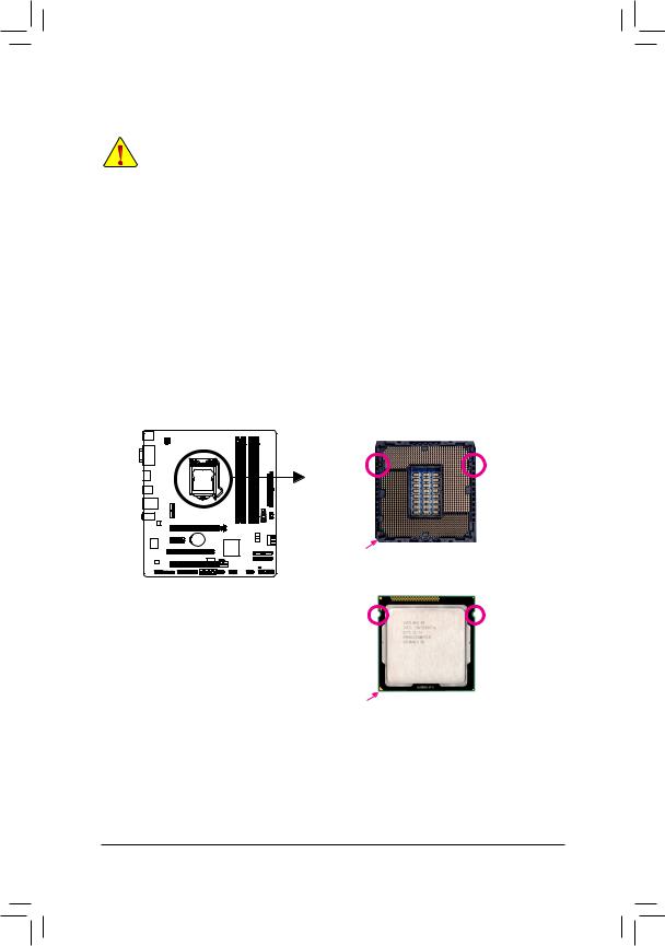
1-3-1 Installing the CPU
A. Locate the alignment keys on the motherboard CPU socket and the notches on the CPU.
LGA1155 CPU Socket
|
Alignment Key |
Alignment Key |
Pin One Corner of the CPU Socket
Triangle Pin One Marking on the CPU
|
— 13 — |
Hardware Installation |

B. Follow the steps below to correctly install the CPU into the motherboard CPU socket.
Before installing the CPU, make sure to turn off the computer and unplug the power cord from the power outlet to prevent damage to the CPU.
Step 1:
Gently press the CPU socket lever handle down and away from the socket with your finger. Then completely lift the CPU socket lever and the metal load plate will be lifted as well.
Step 3:
Hold the CPU with your thumb and index fingers.
Align the CPU pin one marking (triangle) with the pin one corner of the CPU socket (or you may align the CPU notches with the socket alignment keys) and gently insert the CPU into position.
Step 2:
Remove the CPU socket cover as shown. Hold your indexfingerdownonthereargripofthesocketcover and use your thumb to lift up the front edge (next to the «REMOVE» mark) and then remove the cover. (DO NOT touch socket contacts. To protect the CPU socket, always replace the protective socket cover when the CPU is not installed.)
Step 4:
Once the CPU is properly inserted, use one hand to hold the socket lever and use the other to lightly replace the load plate. When replacing the load plate, make sure the front end of the load plate is under the shoulder screw.
|
Step 5: |
NOTE: |
|||
|
Push the CPU socket lever back into its locked |
Hold the CPU socket lever by the handle, not the |
|||
|
position. |
lever base portion. |
|||
|
Hardware Installation |
— 14 — |
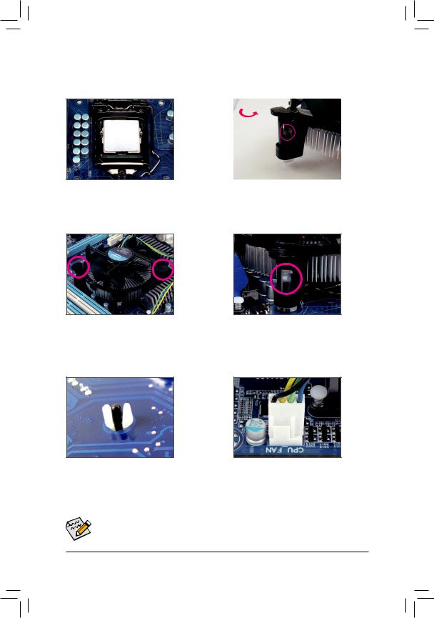
1-3-2 Installing the CPU Cooler
Follow the steps below to correctly install the CPU cooler on the motherboard. (The following procedure uses Intel® boxed cooler as the example cooler.)
Step 1:
Apply an even and thin layer of thermal grease on the surface of the installed CPU.
Step 3:
Place the cooler atop the CPU, aligning the four push pins through the pin holes on the motherboard. Push down on the push pins diagonally.
Step 5:
After the installation, check the back of the motherboard. If the push pin is inserted as the picture above shows, the installation is complete.
|
Male |
||||||
|
Direction of |
Push Pin |
|||||
|
the Arrow Sign |
The Top |
|||||
|
on the Male |
||||||
|
of Female |
||||||
|
Push Pin |
||||||
|
Push Pin |
||||||
|
Female |
||||||
|
Push Pin |
||||||
Step 2:
Before installing the cooler, note the direction of the arrow sign on the male push pin. (Turning the push pin along the direction of arrow is to remove the cooler, on the contrary, is to install.)
Step 4:
You should hear a «click» when pushing down each push pin. Check that the Male and Female push pins are joined closely.
(Refer to your CPU cooler installation manual for instructions on installing the cooler.)
Step 6:
Finally, attach the power connector of the CPU cooler to the CPU fan header (CPU_FAN) on the motherboard.
 Use extreme care when removing the CPU cooler because the thermal grease/tape between the
CPU cooler and CPU may adhere to the CPU. Inadequately removing the CPU cooler may damage the CPU.
|
— 15 — |
Hardware Installation |
1-4 Installing the Memory
Read the following guidelines before you begin to install the memory:
•• Make sure that the motherboard supports the memory. It is recommended that memory of the same capacity, brand, speed, and chips be used.
(Go to GIGABYTE’s website for the latest supported memory speeds and memory modules.)
•• Always turn off the computer and unplug the power cord from the power outlet before installing the memory to prevent hardware damage.
•• Memory modules have a foolproof design. A memory module can be installed in only one direction. If you are unable to insert the memory, switch the direction.
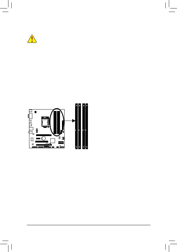
1-4-1 Dual Channel Memory Configuration
This motherboard provides four DDR3 memory sockets and supports Dual Channel Technology. After the memory is installed, the BIOS will automatically detect the specifications and capacity of the memory. Enabling
Dual Channel memory mode will double the original memory bandwidth.
The four DDR3 memory sockets are divided into two channels and each channel has two memory sockets as following:
Channel A: DDR3_1, DDR3_3Channel B: DDR3_2, DDR3_4
Dual Channel Memory Configurations Table
|
DDR3_4 |
DDR3_2 |
DDR3_3 |
DDR3_1 |
|
|
Two Modules |
— — |
DS/SS |
— — |
DS/SS |
|
DS/SS |
— — |
DS/SS |
— — |
|
|
Four Modules |
DS/SS |
DS/SS |
DS/SS |
DS/SS |
(SS=Single-Sided, DS=Double-Sided, «- -«=No Memory)
DDR3_1
DDR3_3
DDR3_2
DDR3_4
Due to CPU limitations, read the following guidelines before installing the memory in Dual Channel mode.
1.Dual Channel mode cannot be enabled if only one DDR3 memory module is installed.
2.When enabling Dual Channel mode with two or four memory modules, it is recommended that memory of the same capacity, brand, speed, and chips be used and installed in the same colored DDR3 sockets. For optimum performance, when enabling Dual Channel mode with two memory modules, we recommend that you install them in the DDR3_1 and DDR3_2 sockets.
|
Hardware Installation |
— 16 — |
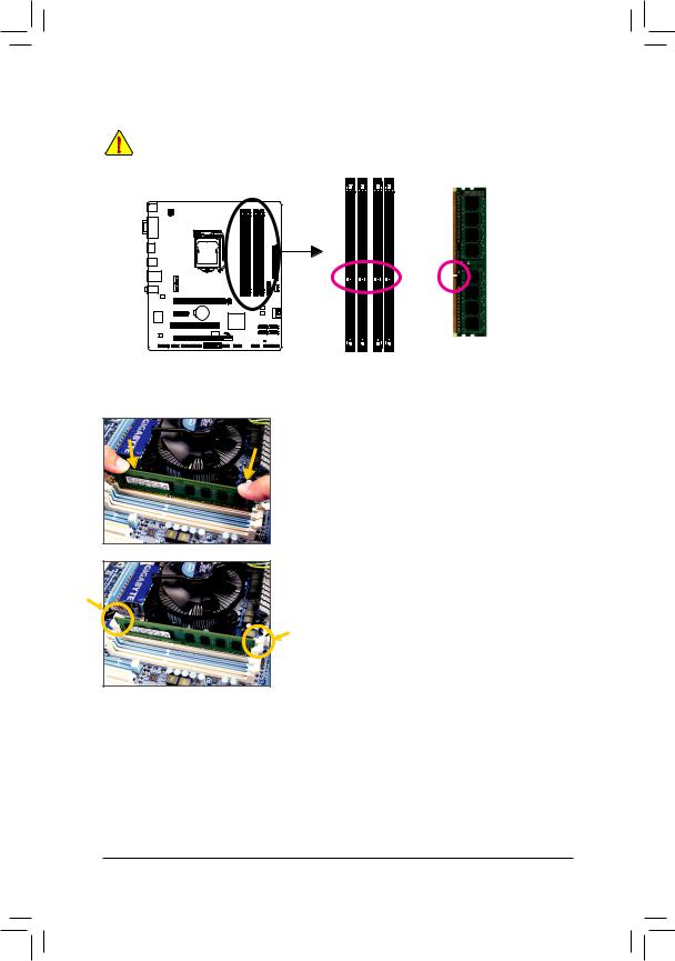
1-4-2 Installing a Memory
Before installing a memory module, make sure to turn off the computer and unplug the power cord from the power outlet to prevent damage to the memory module. DDR3 and DDR2 DIMMs are not compatible to each other or DDR DIMMs. Be sure to install DDR3 DIMMs on this motherboard.
Notch
DDR3 DIMM
ADDR3 memory module has a notch, so it can only fit in one direction. Follow the steps below to correctly install your memory modules in the memory sockets.
Step 1:
Note the orientation of the memory module. Spread the retaining clips at both ends of the memory socket. Place the memory module on the socket. As indicated in the picture on the left, place your fingers on the top edge of the memory, push down on the memory and insert it vertically into the memory socket.
Step 2:
The clips at both ends of the socket will snap into place when the memory module is securely inserted.
|
— 17 — |
Hardware Installation |
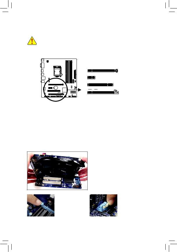
1-5 Installing an Expansion Card
Read the following guidelines before you begin to install an expansion card:
•• Make sure the motherboard supports the expansion card. Carefully read the manual that came with your expansion card.
•• Always turn off the computer and unplug the power cord from the power outlet before installing an expansion card to prevent hardware damage.
PCI Express x16 Slot (PCIEX16)
PCI Express x1 Slot
PCI Slot
PCI Express x16 Slot (PCIEX4)
Follow the steps below to correctly install your expansion card in the expansion slot.
1.Locate an expansion slot that supports your card. Remove the metal slot cover from the chassis back panel.
2.Align the card with the slot, and press down on the card until it is fully seated in the slot.
3.Make sure the metal contacts on the card are completely inserted into the slot.
4.Secure the card’s metal bracket to the chassis back panel with a screw.
5.After installing all expansion cards, replace the chassis cover(s).
6.Turn on your computer. If necessary, go to BIOS Setup to make any required BIOS changes for your expansion card(s).
7.Install the driver provided with the expansion card in your operating system.
Example: Installing and Removing a PCI Express Graphics Card:
•• Installing a Graphics Card:
Gently push down on the top edge of the card until it is fully inserted into the PCI Express slot. Make sure the card is securely seated in the slot and does not rock.
|
•• |
Removing the Card from |
•• Removing the Card from |
||
|
the PCIEX16 Slot: |
the PCIEX4 Slot: |
|||
|
Gently push back on the |
Press the latch at the end |
|||
|
lever on the slot and then |
of the PCI Express slot to |
|||
|
lift the card straight out |
release the card and then |
|||
|
from the slot. |
pull the card straight up |
|||
|
from the slot. |
||||
|
Hardware Installation |
— 18 — |
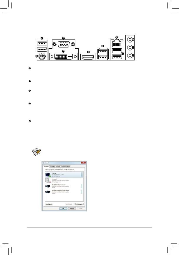
1-6 Back Panel Connectors
USB 2.0/1.1 Port
The USB port supports the USB 2.0/1.1 specification. Use this port for USB devices such as a USB keyboard/mouse, USB printer, USB flash drive and etc.
PS/2 Keyboard/Mouse Port
Use this port to connect a PS/2 mouse or keyboard.
D-Sub Port
The D-Sub port supports a 15-pin D-Sub connector. Connect a monitor that supports D-Sub connection to this port.
DVI-D Port (Note)
The DVI-D port conforms to the DVI-D specificationand supports a maximum resolution of 1920×1200
(the actual resolutions supported depend on the monitor being used). Connect a monitor that supports DVI-D connection to this port.
HDMI Port
HDMI (High-Definition Multimedia Interface) is an all-digital audio/video interface capable of transmitting uncompressed audio/video signals. The HDMI port is HDCP compliant and supports Dolby TrueHD and DTS HDMaster Audio formats. It also supports up to 192KHz/24bit 8-channel LPCM audio output. You can use this port to connect your HDMI-supported audio/video device. The maximum supported resolution is 1920×1200, but the actual resolutions supported are dependent on the monitor being used.

 After installing the HDMI device, make sure to set the default sound playback device to HDMI.
(The item name may differ depending on your operating system. The screenshot below is from Windows 7.)
In Windows 7, select Start>Control Panel>Hardware and Sound>Sound>Playback, set Intel(R) Display Audio to the default playback device.
|
(Note) The DVI-D port does not support D-Sub connection by adapter. |
|
|
— 19 — |
Hardware Installation |
Dual Display Configurations for the Onboard Graphics:
This motherboard provides three video output ports: D-Sub, DVI-D, and HDMI. Dual monitor confgurations are supported in operating system environment only, but not during the BIOS Setup or POST process.
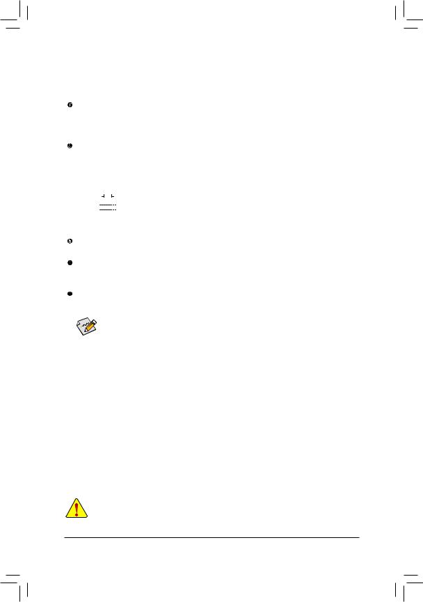
USB 3.0/2.0 Port
The USB 3.0 port supports the USB 3.0 specification and is compatible to the USB 2.0/1.1 specification.
Use this port for USB devices Use this port for USB devices such as a USB keyboard/mouse, USB printer,
USB flash drive and etc.
RJ-45 LAN Port
The Gigabit Ethernet LAN port provides Internet connection at up to 1 Gbps data rate. The following describes the states of the LAN port LEDs.
|
Connection/ |
Connection/Speed LED: |
Activity LED: |
|||||||||||||||||
|
Speed LED |
Activity LED |
||||||||||||||||||
|
State |
Description |
State |
Description |
||||||||||||||||
|
Orange |
1 Gbps data rate |
Blinking |
Data transmission or receiving is occurring |
||||||||||||||||
|
Green |
100 Mbps data rate |
Off |
No data transmission or receiving is occurring |
||||||||||||||||
|
Off |
10 Mbps data rate |
||||||||||||||||||
|
LAN Port |
|||||||||||||||||||
Line In Jack (Blue)
The default line in jack. Use this audio jack for line in devices such as an optical drive, walkman, etc.
Line Out Jack (Green)
The default line out jack. Use this audio jack for a headphone or 2-channel speaker. This jack can be used to connect front speakers in a 4/5.1/7.1-channel audio configuration.
Mic In Jack (Pink)
The default Mic in jack. Microphones must be connected to this jack.

 To configure 7.1-channel audio, you have to use an HD front panel audio module and enable
the multi-channel audio feature through the audio driver. Refer to the instructions on setting up a
2/4/5.1/7.1-channel audio configuration in Chapter 5, «Configuring 2/4/5.1/7.1-Channel Audio.»
•• When removing the cable connected to a back panel connector, first remove the cable from your device and then remove it from the motherboard.
•• When removing the cable, pull it straight out from the connector. Do not rock it side to side to prevent an electrical short inside the cable connector.
|
Hardware Installation |
— 20 — |
![]()
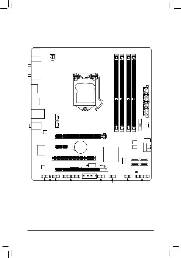
1-7 Internal Connectors
1
|
2 |
|
|
4 |
|
|
3 |
4 |
|
11 |
|
|
5 |
6 |
|
7 |
|
|
10 |
16 |
|
9 |
13 |
14 |
15 |
12 |
8 |
|
1) |
ATX_12V |
9) |
F_AUDIO |
|
2) |
ATX |
10) |
SPDIF_O |
|
3) |
CPU_FAN |
11) |
F_USB30 |
|
4) |
SYS_FAN1/SYS_FAN2 |
12) |
F_USB1/2/3 |
|
5) |
BAT |
13) |
COM |
|
6) |
SATA3 0/1 |
14) |
LPT |
|
7) |
SATA2 2/3/4/5 |
15) |
TPM |
|
|
F_PANEL |
16) |
CLR_CMOS |
Read the following guidelines before connecting external devices:
•• First make sure your devices are compliant with the connectors you wish to connect.
•• Before installing the devices, be sure to turn off the devices and your computer. Unplug the power cord from the power outlet to prevent damage to the devices.
•• After installing the device and before turning on the computer, make sure the device cable has been securely attached to the connector on the motherboard.
|
— 21 — |
Hardware Installation |
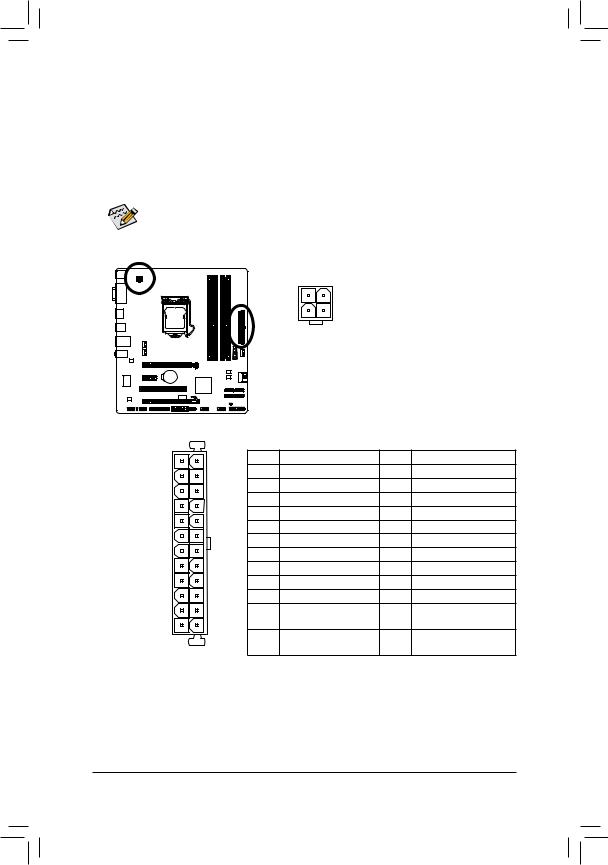
1/2) ATX_12V/ATX (2×2 12V Power Connector and 2×12 Main Power Connector)
With the use of the power connector, the power supply can supply enough stable power to all the components on the motherboard. Before connecting the power connector, first make sure the power supply is turned off and all devices are properly installed. The power connector possesses a foolproof design. Connect the power supply cable to the power connector in the correct orientation.
The 12V power connector mainly supplies power to the CPU. If the 12V power connector is not connected, the computer will not start.
To meet expansion requirements, it is recommended that a power supply that can withstand high power consumption be used (500W or greater). If a power supply is used that does not provide the required power, the result can lead to an unstable or unbootable system.
|
ATX_12V |
||||
|
Pin No. |
Definition |
|||
|
2 |
1 |
1 |
GND |
|
|
4 |
3 |
2 |
GND |
|
|
3 |
+12V |
|||
|
ATX_12V |
4 |
+12V |
||
|
ATX: |
|||||
|
12 |
24 |
Pin No. |
Definition |
Pin No. |
Definition |
|
1 |
3.3V |
13 |
3.3V |
||
|
2 |
3.3V |
14 |
-12V |
||
|
3 |
GND |
15 |
GND |
||
|
4 |
+5V |
16 |
PS_ON (soft On/Off) |
||
|
5 |
GND |
17 |
GND |
||
|
6 |
+5V |
18 |
GND |
||
|
7 |
GND |
19 |
GND |
||
|
8 |
Power Good |
20 |
-5V |
||
|
9 |
5VSB (stand by +5V) |
21 |
+5V |
||
|
10 |
+12V |
22 |
+5V |
||
|
11 |
+12V (Only for 2×12-pin |
23 |
+5V (Only for 2×12-pin ATX) |
||
|
1 |
13 |
12 |
ATX) |
24 |
GND (Only for 2×12-pin |
|
3.3V (Only for 2×12-pin |
|||||
|
ATX |
ATX) |
ATX) |
|||
|
Hardware Installation |
— 22 — |
3/4) CPU_FAN/SYS_FAN1/SYS_FAN2 (Fan Headers)
All fan headers on this motherboard are 4-pin. Most fan headers possess a foolproof insertion design. When connecting a fan cable, be sure to connect it in the correct orientation (the black connector wire is the ground wire). The speed control function requires the use of a fan with fan speed control design. For optimum heat dissipation, it is recommended that a system fan be installed inside the chassis.
|
CPU_FAN: |
||||
|
Pin No. |
Definition |
|||
|
1 |
GND |
|||
|
2 |
+12V |
|||
|
1 |
||||
|
CPU_FAN |
3 |
Sense |
||
|
4 |
Speed Control |
|||
|
SYS_FAN1/SYS_FAN2: |
||||
|
Pin No. |
Definition |
|||
|
1 |
GND |
|||
|
2 |
+12V |
|||
|
1 |
||||
|
SYS_FAN1/SYS_FAN2 |
3 |
Sense |
||
|
4 |
Reserve |
•• Be sure to connect fan cables to the fan headers to prevent your CPU and system from overheating. Overheating may result in damage to the CPU or the system may hang.
•• These fan headers are not configuration jumper blocks. Do not place a jumper cap on the headers.
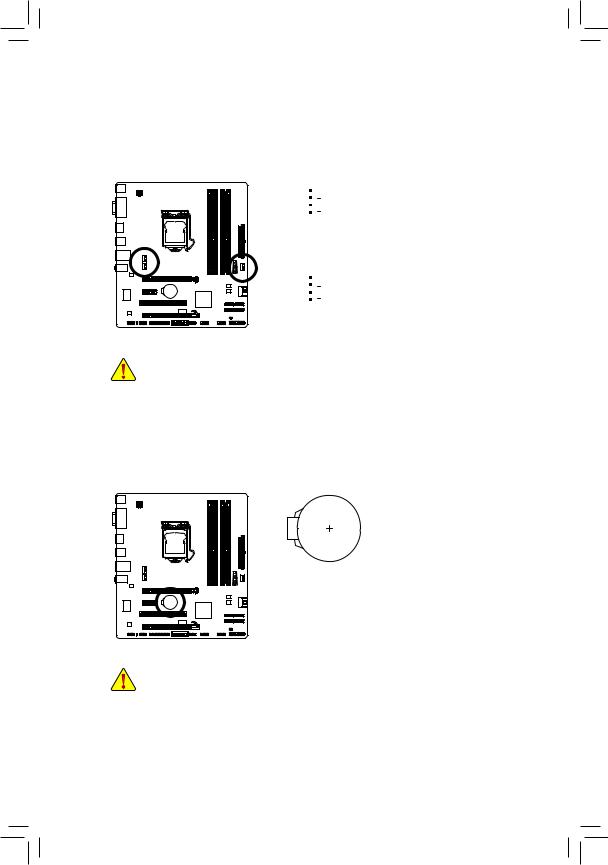
5)BAT (Battery)
The battery provides power to keep the values (such as BIOS configurations, date, and time information) in the CMOS when the computer is turned off. Replace the battery when the battery voltage drops to a low level, or the CMOS values may not be accurate or may be lost.
|
You may clear the CMOS values by removing the battery: |
||
|
1. |
Turn off your computer and unplug the power cord. |
|
|
2. |
Gently remove the battery from the battery holder and wait for one minute. |
|
|
(Or use a metal object like a screwdriver to touch the positive and negative |
||
|
terminals of the battery holder, making them short for 5 seconds.) |
||
|
3. |
Replace the battery. |
|
|
4. |
Plug in the power cord and restart your computer. |
|
|
•• |
Always turn off your computer and unplug the power cord before replacing the battery. |
|
|
•• |
Replace the battery with an equivalent one. Danger of explosion if the battery is replaced with |
|
|
an incorrect model. |
•• Contact the place of purchase or local dealer if you are not able to replace the battery by yourself
|
or uncertain about the battery model. |
||
|
•• |
When installing the battery, note the orientation of the positive side (+) and the negative side (-) of |
|
|
the battery (the positive side should face up). |
||
|
•• |
Used batteries must be handled in accordance with local environmental regulations. |
|
|
— 23 — |
Hardware Installation |
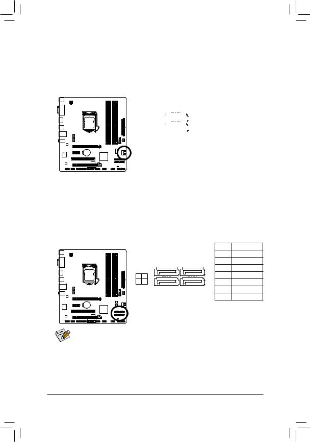
6)SATA3 0/1 (SATA 6Gb/s Connectors, Controlled by Intel Z77/H77 Chipset)
The SATA connectors conform to SATA 6Gb/s standard and are compatible with SATA 3Gb/s and SATA 1.5Gb/s standard. Each SATA connector supports a single SATA device. The SATA3 0/1 connectors support RAID 0 and RAID 1. RAID 5 and RAID 10 can be implemented on the two connectors with the SATA2 2/3/4/5 connector (Note).Refer toChapter 5, «Configuring SATAHard Drive(s),» for instructions on configuring a RAID array.
|
Pin No. |
Definition |
||||||||||
|
SATA3 |
1 |
GND |
|||||||||
|
7 |
1 |
2 |
TXP |
||||||||
|
1 |
7 |
1 |
3 |
TXN |
|||||||
|
0 |
|||||||||||
|
4 |
GND |
||||||||||
|
5 |
RXN |
||||||||||
|
6 |
RXP |
||||||||||
|
7 |
GND |
7) SATA2 2/3/4/5 (SATA 3Gb/s Connectors, Controlled by Intel Z77/H77 Chipset)
The SATA connectors conform to SATA 3Gb/s standard and are compatible with SATA 1.5Gb/s standard. Each SATA connector supports a single SATA device. The Intel Z77/H77 Chipset supports RAID 0, RAID 1,
RAID 5, and RAID 10. Refer to Chapter 5, «Configuring SATAHard Drive(s),» for instructions on configuring
|
a RAID array. |
Pin No. |
Definition |
||||
|
1 |
GND |
|||||
|
2 |
TXP |
|||||
|
SATA2 |
7 |
1 |
3 |
TXN |
||
|
4 |
GND |
|||||
|
2 |
3 |
|||||
|
4 |
5 7 |
1 |
5 |
RXN |
||
|
6 |
RXP |
|||||
|
7 |
GND |
•• A RAID 0 or RAID 1 configuration requires at least two hard drives. If more than two hard drives are to be used, the total number of hard drives must be an even number.
•• ARAID 5 configuration requires at least three hard drives. (The total number of hard drives does not have to be an even number.)
•• ARAID 10 configuration requires four hard drives.
(Note) When a RAID set is built across the SATA 6Gb/s and SATA 3Gb/s channels, the system performance of the RAID set may vary depending on the devices being connected.
|
Hardware Installation |
— 24 — |
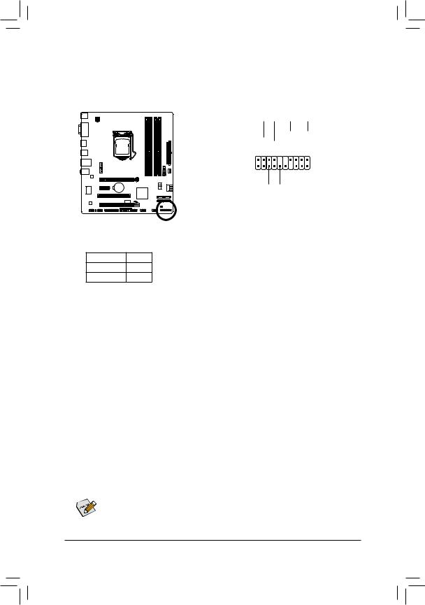
 F_PANEL (Front Panel Header)
Connect the power switch, reset switch, speaker, chassis intrusion switch/sensor and system status indicator on the chassis to this header according to the pin assignments below. Note the positive and negative pins before connecting the cables.
|
Message/Power/ |
Power |
|||||||||||||||||
|
Sleep LED |
Switch |
Speaker |
||||||||||||||||
|
MSG+ MSG |
-PW |
SPEAK+ |
-SPEAK |
|||||||||||||||
|
— |
PW+ |
|||||||||||||||||
|
2 |
20 |
|||||||||||||||||
|
1 |
19 |
|||||||||||||||||
|
HD+ |
RES |
-CI |
PWR+ -PWR |
|||||||||||||||
|
HD- |
RES+ |
CI+ |
||||||||||||||||
|
— |
||||||||||||||||||
|
Hard Drive |
Reset |
Power LED |
||||||||||||||||
|
Activity LED |
Switch |
|||||||||||||||||
|
Chassis |
||||||||||||||||||
|
Intrusion Header |
•• MSG/PWR (Message/Power/Sleep LED):
|
System Status |
LED |
|
S0 |
On |
|
S3/S4/S5 |
Off |
Connects to the power status indicator on the chassis front panel. The LED is on when the system is operating. The LED is off when the system is in S3/S4 sleep state or powered off (S5).
•• PW (Power Switch):
Connectstothepowerswitchonthechassisfrontpanel.Youmayconfigurethewaytoturnoffyoursystem using the power switch (refer to Chapter 2, «BIOS Setup,» «Power Management,» for more information).
•• Speaker (Speaker):
Connects to the speaker on the chassis front panel. The system reports system startup status by issuing a beep code. One single short beep will be heard if no problem is detected at system startup.
•• HD (Hard Drive Activity LED):
Connects to the hard drive activity LED on the chassis front panel. The LED is on when the hard drive is reading or writing data.
•• RES (Reset Switch):
Connects to the reset switch on the chassis front panel. Press the reset switch to restart the computer if the computer freezes and fails to perform a normal restart.
•• CI (Chassis Intrusion Header):
Connects to the chassis intrusion switch/sensor on the chassis that can detect if the chassis cover has been removed. This function requires a chassis with a chassis intrusion switch/sensor.

 The front panel design may differ by chassis. A front panel module mainly consists of power switch,
reset switch, power LED, hard drive activity LED, speaker and etc. When connecting your chassis front panel module to this header, make sure the wire assignments and the pin assignments are matched correctly.
|
— 25 — |
Hardware Installation |
9)F_AUDIO (Front Panel Audio Header)
The front panel audio header supports Intel High Definition audio (HD) andAC’97 audio. You may connect your chassis front panel audio module to this header. Make sure the wire assignments of the module connector match the pin assignments of the motherboard header. Incorrect connection between the module connector and the motherboard header will make the device unable to work or even damage it.
|
For HD Front Panel Audio: |
For AC’97 Front Panel Audio: |
||||||
|
Pin No. |
Definition |
Pin No. |
Definition |
||||
|
1 |
MIC2_L |
1 |
MIC |
||||
|
9 |
1 |
2 |
GND |
2 |
GND |
||
|
10 |
2 |
||||||
|
3 |
MIC2_R |
3 |
MIC Power |
||||
|
4 |
-ACZ_DET |
4 |
NC |
||||
|
5 |
LINE2_R |
5 |
Line Out (R) |
||||
|
6 |
GND |
6 |
NC |
||||
|
7 |
FAUDIO_JD |
7 |
NC |
||||
|
8 |
No Pin |
8 |
No Pin |
||||
|
9 |
LINE2_L |
9 |
Line Out (L) |
||||
|
10 |
GND |
10 |
NC |
•• The front panel audio header supports HD audio by default. If your chassis provides an AC’97 front panel audio module, refer to the instructions on how to activate AC’97 functionality via the audio software in Chapter 5, «Configuring 2/4/5.1/7.1-Channel Audio.»
•• Audio signals will be present on both of the front and back panel audio connections simultaneously. If you want to mute the back panel audio (only supported when using an HD front panel audio module), refer to Chapter 5, «Configuring 2/4/5.1/7.1-Channel Audio.»
•• Some chassis provide a front panel audio module that has separated connectors on each wire instead of a single plug. For information about connecting the front panel audio module that has different wire assignments, please contact the chassis manufacturer.
10)SPDIF_O (S/PDIF Out Header)
This header supports digital S/PDIF Out and connects a S/PDIF digital audio cable (provided by expansion cards) for digital audio output from your motherboard to certain expansion cards like graphics cards and sound cards. For example, some graphics cards may require you to use a S/PDIF digital audio cable for digital audio output from your motherboard to your graphics card if you wish to connect an HDMI display to the graphics card and have digital audio output from the HDMI display at the same time. For information about connecting the S/PDIF digital audio cable, carefully read the manual for your expansion card.
|
Pin No. |
Definition |
|
|
1 |
SPDIFO |
|
|
1 |
2 |
GND |
|
Hardware Installation |
— 26 — |

11)F_USB30 (USB 3.0/2.0 Header)
The header conforms to USB 3.0/2.0 specification and can provide two USB ports. For purchasing the optional 3.5″ front panel that provides two USB 3.0/2.0 ports, please contact the local dealer.
|
Pin No. |
Definition |
Pin No. |
Definition |
||
|
1 |
VBUS |
11 |
D2+ |
||
|
20 |
1 |
2 |
SSRX1- |
12 |
D2- |
|
3 |
SSRX1+ |
13 |
GND |
||
|
4 |
GND |
14 |
SSTX2+ |
||
|
5 |
SSTX1- |
15 |
SSTX2- |
||
|
6 |
SSTX1+ |
16 |
GND |
||
|
7 |
GND |
17 |
SSRX2+ |
||
|
11 |
10 |
8 |
D1- |
18 |
SSRX2- |
|
9 |
D1+ |
19 |
VBUS |
||
|
10 |
NC |
20 |
No Pin |
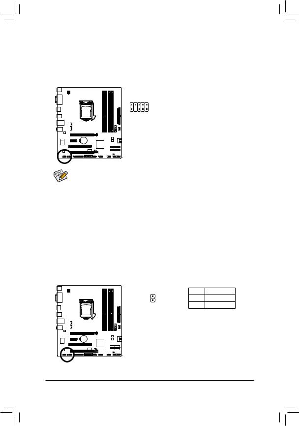
12)F_USB1/2/3 (USB 2.0/1.1 Headers)
The headers conform to USB 2.0/1.1 specification. Each USB header can provide two USB ports via an optional USB bracket. For purchasing the optional USB bracket, please contact the local dealer.
|
Pin No. |
Definition |
|||
|
1 |
Power (5V) |
|||
|
9 |
1 |
2 |
Power (5V) |
|
|
3 |
USB DX- |
|||
|
10 |
2 |
|||
|
4 |
USB DY- |
|||
|
5 |
USB DX+ |
|||
|
6 |
USB DY+ |
|||
|
7 |
GND |
|||
|
8 |
GND |
|||
|
9 |
No Pin |
|||
|
10 |
NC |
•• Do not plug the IEEE 1394 bracket (2×5-pin) cable into the USB 2.0/1.1 header.
•• Prior to installing the USB bracket, be sure to turn off your computer and unplug the power cord from the power outlet to prevent damage to the USB bracket.
|
— 27 — |
Hardware Installation |
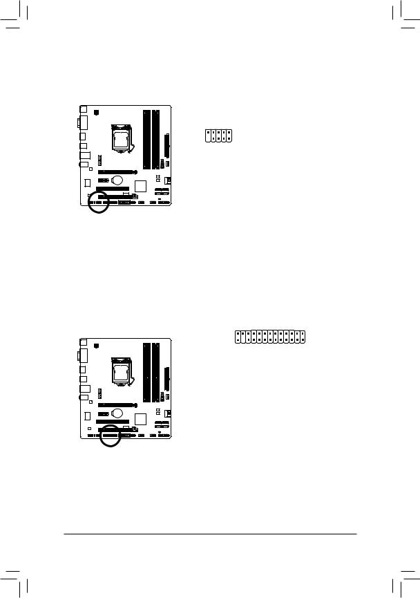
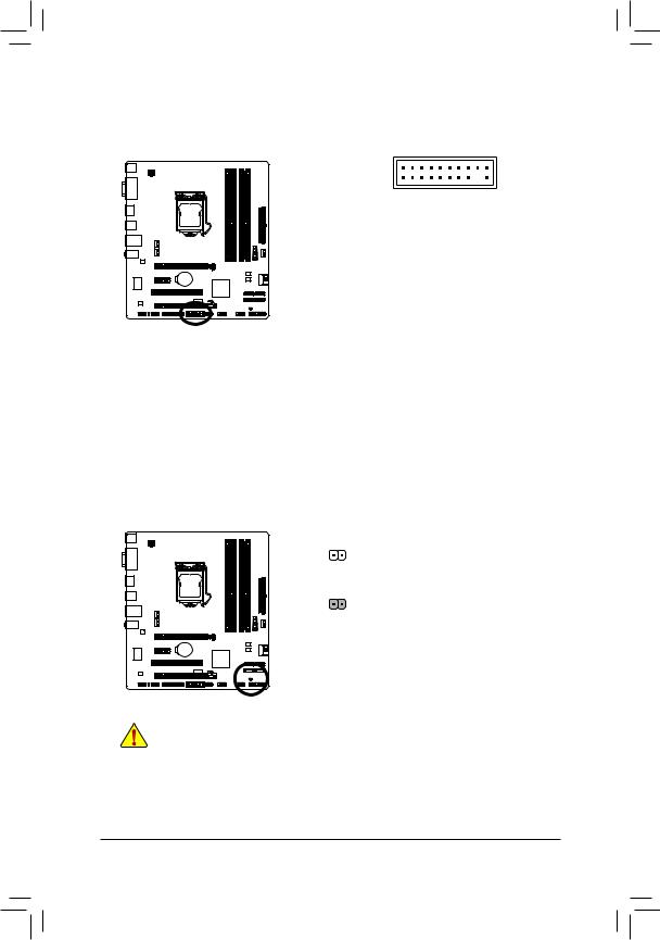
13)COM (Serial Port Header)
The COM header can provide one serial port via an optional COM port cable. For purchasing the optional COM port cable, please contact the local dealer.
|
Pin No. |
Definition |
|||
|
1 |
NDCD- |
|||
|
9 |
1 |
2 |
NSIN |
|
|
3 |
NSOUT |
|||
|
10 |
2 |
|||
|
4 |
NDTR- |
|||
|
5 |
GND |
|||
|
6 |
NDSR- |
|||
|
7 |
NRTS- |
|||
|
8 |
NCTS- |
|||
|
9 |
NRI- |
|||
|
10 |
No Pin |
14)LPT (Parallel Port Header)
The LPT header can provide one parallel port via an optional LPT port cable. For purchasing the optional LPT port cable, please contact the local dealer.
|
25 |
1 |
||
|
26 |
2 |
||
|
Pin No. |
Definition |
Pin No. |
Definition |
|
1 |
STB- |
14 |
GND |
|
2 |
AFD- |
15 |
PD6 |
|
3 |
PD0 |
16 |
GND |
|
4 |
ERR- |
17 |
PD7 |
|
5 |
PD1 |
18 |
GND |
|
6 |
INIT- |
19 |
ACK- |
|
7 |
PD2 |
20 |
GND |
|
8 |
SLIN- |
21 |
BUSY |
|
9 |
PD3 |
22 |
GND |
|
10 |
GND |
23 |
PE |
|
11 |
PD4 |
24 |
No Pin |
|
12 |
GND |
25 |
SLCT |
|
13 |
PD5 |
26 |
GND |
|
Hardware Installation |
— 28 — |
15)TPM (Trusted Platform Module Header)
You may connect a TPM (Trusted Platform Module) to this header.
|
19 |
1 |
||
|
20 |
2 |
||
|
Pin No. |
Definition |
Pin No. |
Definition |
|
1 |
LCLK |
11 |
LAD0 |
|
2 |
GND |
12 |
GND |
|
3 |
LFRAME |
13 |
NC |
|
4 |
No Pin |
14 |
ID |
|
5 |
LRESET |
15 |
SB3V |
|
6 |
NC |
16 |
SERIRQ |
|
7 |
LAD3 |
17 |
GND |
|
8 |
LAD2 |
18 |
NC |
|
9 |
VCC3 |
19 |
NC |
|
10 |
LAD1 |
20 |
SUSCLK |
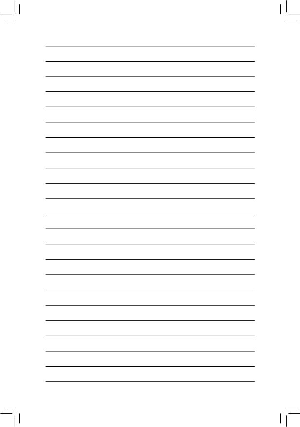
16)CLR_CMOS (Clear CMOS Jumper)
Use this jumper to clear the CMOS values (e.g. date information and BIOS configurations) and reset the
CMOS values to factory defaults. To clear the CMOS values, use a metal object like a screwdriver to touch the two pins for a few seconds.
Open: Normal
Short: Clear CMOS Values
•• Always turn off your computer and unplug the power cord from the power outlet before clearing the CMOS values.
•• After system restart, go to BIOS Setup to load factory defaults (select Load Optimized
Defaults) or manually configure the BIOS settings (refer to Chapter 2, «BIOS Setup,» for BIOS configurations).
|
— 29 — |
Hardware Installation |
|
Hardware Installation |
— 30 — |
![]()
Chapter 2 BIOS Setup
BIOS (Basic Input and Output System) records hardware parameters of the system in the CMOS on the motherboard. Its major functions include conducting the Power-On Self-Test (POST) during system startup, saving system parameters and loading operating system, etc. BIOS includes a BIOS Setup program that allows the user to modify basic system configuration settings or to activate certain system features.
When the power is turned off, the battery on the motherboard supplies the necessary power to the CMOS to keep the configuration values in the CMOS.
To access the BIOS Setup program, press the <Delete> key during the POST when the power is turned on.
To upgrade the BIOS, use either the GIGABYTE Q-Flash or @BIOS utility.
•• Q-Flash allows the user to quickly and easily upgrade or back up BIOS without entering the operating system.
•• @BIOS is a Windows-based utility that searches and downloads the latest version of BIOS from the Internet and updates the BIOS.
For instructions on using the Q-Flash and @BIOS utilities, refer to Chapter 4, «BIOS Update Utilities.»
•• Because BIOS flashing is potentially risky, if you do not encounter problems using the current version of BIOS, it is recommended that you not flash the BIOS. To flash the BIOS, do it with caution. Inadequate BIOS flashing may result in system malfunction.
•• It is recommended that you not alter the default settings (unless you need to) to prevent system instability or other unexpected results. Inadequately altering the settings may result in system’s failure to boot. If this occurs, try to clear the CMOS values and reset the board to default values. (Refer to the «Load Optimized Defaults» section in this chapter or introductions of the battery/clear CMOS jumper in Chapter 1 for how to clear the CMOS values.)

2-1 Startup Screen
The following startup Logo screen will appear when the computer boots.
 Function Keys
Function Keys:
<DEL>: BIOS SETUPQ-FLASH
Press the <Delete> key to enter BIOS Setup or to access the Q-Flash utility in BIOS Setup.
<F9>: SYSTEM INFORMATION
Press the <F9> key to display your system information.
<F12>: BOOT MENU
Boot Menu allows you to set the first boot device without entering BIOS Setup. In Boot Menu, use the up arrow key <h> or the down arrow key <i> to select the first boot device, then press <Enter> to accept.
The system will boot from the device immediately.
Note: The setting in Boot Menu is effective for one time only. After system restart, the device boot order will still be based on BIOS Setup settings.
<END>: Q-FLASH
Press the <End> key to access the Q-Flash utility directly without having to enter BIOS Setup first.