- Manuals
- Brands
- Gigabyte Manuals
- Motherboard
- X570 I AORUS PRO WIFI
- User manual
-
Contents
-
Table of Contents
-
Bookmarks
Quick Links
X570 I AORUS PRO
WIFI
User’s Manual
Rev. 1001
12ME-X57IAPW-1001R
For more product details, please visit GIGABYTE’s website.
To reduce the impacts on global warming, the packaging materials of this product
are recyclable and reusable. GIGABYTE works with you to protect the environment.
Related Manuals for Gigabyte X570 I AORUS PRO WIFI
Summary of Contents for Gigabyte X570 I AORUS PRO WIFI
-
Page 1
X570 I AORUS PRO WIFI User’s Manual Rev. 1001 12ME-X57IAPW-1001R For more product details, please visit GIGABYTE’s website. To reduce the impacts on global warming, the packaging materials of this product are recyclable and reusable. GIGABYTE works with you to protect the environment. -
Page 2
Motherboard X570 I AORUS PRO WIFI Motherboard X570 I AORUS PRO WIFI Jun. 14, 2019 Jun. 14, 2019 Wireless Module Country Approvals:… -
Page 3
Information in this manual is protected by copyright laws and is the property of GIGABYTE. Changes to the specifications and features in this manual may be made by GIGABYTE without prior notice. No part of this manual may be reproduced, copied, translated, transmitted, or published in any form or by any means without GIGABYTE’s prior written permission. -
Page 4: Table Of Contents
Table of Contents X570 I AORUS PRO WIFI Motherboard Layout …………..5 Chapter 1 Hardware Installation ………………6 Installation Precautions ………………6 Product Specifications ………………7 Installing the CPU ………………10 Installing the Memory ………………11 Installing an Expansion Card …………….. 11 Back Panel Connectors ………………
-
Page 5: X570 I Aorus Pro Wifi Motherboard Layout
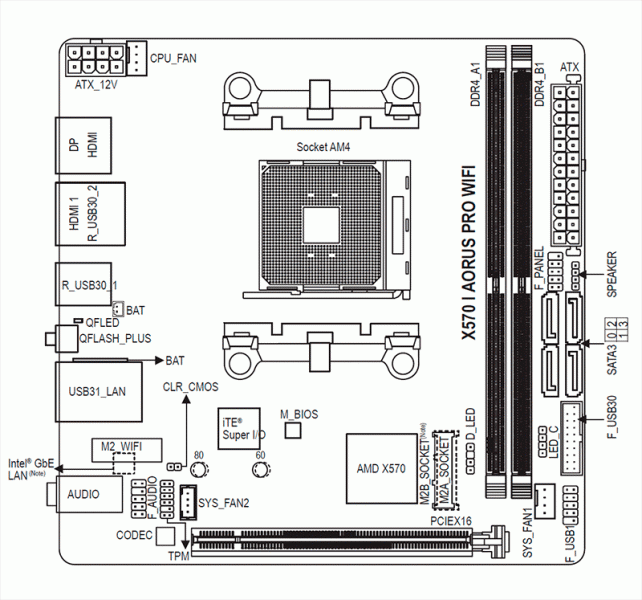
X570 I AORUS PRO WIFI Motherboard Layout CPU_FAN ATX_12V Socket AM4 R_USB30_1 QFLED QFLASH_PLUS CLR_CMOS USB31_LAN M_BIOS ® Super I/O M2_WIFI Intel ® AMD X570 (Note) AUDIO SYS_FAN2 PCIEX16 CODEC Box Contents 5 X570 I AORUS PRO WIFI Motherboard 5 Motherboard driver disk…
-
Page 6: Chapter 1 Hardware Installation
Chapter 1 Hardware Installation Installation Precautions The motherboard contains numerous delicate electronic circuits and components which can become damaged as a result of electrostatic discharge (ESD). Prior to installation, carefully read the user’s manual and follow these procedures: • Prior to installation, make sure the chassis is suitable for the motherboard. •…
-
Page 7: 1-2 Product Specifications
Support for ECC Un-buffered DIMM 1Rx8/2Rx8 memory modules Š Support for non-ECC Un-buffered DIMM 1Rx8/2Rx8/1Rx16 memory modules Support for Extreme Memory Profile (XMP) memory modules Š (Go to GIGABYTE’s website for the latest supported memory speeds and memory modules.) Š Onboard Integrated Graphics Processor:…
-
Page 8
Expansion Slots Integrated in the CPU (PCIEX16): Š 3rd Generation AMD Ryzen ™ processors: 1 x PCI Express x16 slot, supporting PCIe 4.0 and running at x16 Š 2nd Generation AMD Ryzen ™ processors: 1 x PCI Express x16 slot, supporting PCIe 3.0 and running at x16 Š… -
Page 9
Support for Q-Flash Š Support for Xpress Install Please visit GIGABYTE’s website Please visit the SupportUtility List for support lists of CPU, memory page on GIGABYTE’s website to modules, SSDs, and M.2 devices. download the latest version of apps. — 9 -… -
Page 10: Installing The Cpu
Š Form Factor Mini-ITX Form Factor; 17.0cm x 17.0cm * GIGABYTE reserves the right to make any changes to the product specifications and product-related information without prior notice. Installing the CPU Read the following guidelines before you begin to install the CPU: •…
-
Page 11: Installing The Memory
• Make sure that the motherboard supports the memory. It is recommended that memory of the same capacity, brand, speed, and chips be used. (Go to GIGABYTE’s website for the latest supported memory speeds and memory modules.) • Always turn off the computer and unplug the power cord from the power outlet before installing the memory to prevent hardware damage.
-
Page 12
(Note 1) For 2nd Generation AMD Ryzen ™ with Radeon ™ Vega Graphics processors/AMD Ryzen ™ with Radeon ™ Vega Graphics processors only. (Note 2) To enable the Q-Flash Plus function please visit the «Unique Features» webpage of GIGABYTE’s website. — 12 -… -
Page 13
• When removing the cable, pull it straight out from the connector. Do not rock it side to side to prevent an electrical short inside the cable connector. Please visit GIGABYTE’s website for details on configuring the audio software. — 13 -… -
Page 14: Internal Connectors
Internal Connectors ATX_12V F_PANEL F_AUDIO CPU_FAN SPEAKER SYS_FAN1/SYS_FAN2 D_LED F_USB30 LED_C F_USB1 SATA3 0/1/2/3 CLR_CMOS M2A_SOCKET/M2B_SOCKET (Note) (Note) The connector is on the back of the motherboard. Read the following guidelines before connecting external devices: • First make sure your devices are compliant with the connectors you wish to connect. •…
-
Page 15
1/2) ATX_12V/ATX (2×4 12V Power Connector and 2×12 Main Power Connector) With the use of the power connector, the power supply can supply enough stable power to all the components on the motherboard. Before connecting the power connector, first make sure the power supply is turned off and all devices are properly installed. -
Page 16
LED strip. For how to turn on/off the lights of the LED strip please visit the «Unique Features» webpage of GIGABYTE’s website. Before installing the devices, be sure to turn off the devices and your computer. Unplug the power cord from the power outlet to prevent damage to the devices. -
Page 17
7) SATA3 0/1/2/3 (SATA 6Gb/s Connectors) The SATA connectors conform to SATA 6Gb/s standard and are compatible with SATA 3Gb/s and SATA 1.5Gb/s standard. Each SATA connector supports a single SATA device. The SATA connectors support RAID 0, RAID 1, and RAID 10. Refer to Chapter 3, «Configuring a RAID Set,» for instructions on configuring a RAID array. -
Page 18
M2B_SOCKET (Note) Follow the steps below to correctly install an M.2 SSD in the M2B_SOCKET connector. Step 1: Use a screw driver to unfasten the screw and standoff from the motherboard. Locate the proper mounting hole for the M.2 SSD to be installed and then screw the standoff first. Step 2: Slide the M.2 SSD into the connector at an angle. -
Page 19
10) F_AUDIO (Front Panel Audio Header) The front panel audio header supports High Definition audio (HD). You may connect your chassis front panel audio module to this header. Make sure the wire assignments of the module connector match the pin assignments of the motherboard header. Incorrect connection between the module connector and the motherboard header will make the device unable to work or even damage it. -
Page 20
13) F_USB30 (USB 3.1 Gen 1 Header) The header conforms to USB 3.1 Gen 1 and USB 2.0 specification and can provide two USB ports. For purchasing the optional 3.5″ front panel that provides two USB 3.1 Gen 1 ports, please contact the local dealer. -
Page 21
15) CLR_CMOS (Clear CMOS Jumper) Use this jumper to clear the BIOS configuration and reset the CMOS values to factory defaults. To clear the CMOS values, use a metal object like a screwdriver to touch the two pins for a few seconds. Open: Normal Short: Clear CMOS Values •… -
Page 22: Chapter 2 Bios Setup
CMOS. To access the BIOS Setup program, press the <Delete> key during the POST when the power is turned on. To upgrade the BIOS, use either the GIGABYTE Q-Flash or @BIOS utility. • Q-Flash allows the user to quickly and easily upgrade or back up BIOS without entering the operating system.
-
Page 23: The Main Menu
The Main Menu System Time Setup Menus Configuration Items Hardware Information Option Description Current Settings Quick Access Bar allows you to quickly move to the General Help, Easy Mode, Smart Fan 5, or Q-Flash screen. Advanced Mode Function Keys <f><g> Move the selection bar to select a setup menu Move the selection bar to select an configuration item on a menu <h><i>…
-
Page 24: Favorites (F11)
Favorites (F11) Set your frequently used options as your favorites and use the <F11> key to quickly switch to the page where all of your favorite options are located. To add or remove a favorite option, go to its original page and press <Insert>…
-
Page 25: Tweaker
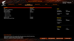
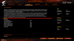
Tweaker Whether the system will work stably with the overclock/overvoltage settings you made is dependent on your overall system configurations. Incorrectly doing overclock/overvoltage may result in damage to CPU, chipset, or memory and reduce the useful life of these components. This page is for advanced users only and we recommend you not to alter the default settings to prevent system instability or other unexpected results.
-
Page 26
& SMT Mode Allows you to enable or disable the CPU Simultaneous Multi-Threading technology. This feature only works for operating systems that support multi-processor mode. Auto lets the BIOS automatically configure this setting. (Default: Auto) & AMD CPU fTPM Enables or disables the TPM 2.0 function integrated in the AMD CPU. (Default: Disabled) &… -
Page 27: Settings
Settings ƒ Platform Power & AC BACK Determines the state of the system after the return of power from an AC power loss. Memory The system returns to its last known awake state upon the return of the AC power. Always On The system is turned on upon the return of the AC power.
-
Page 28
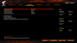
ƒ IO Ports & Integrated Graphics (Note) Enables or disables the onboard graphics function. Auto The BIOS will automatically enable or disable the onboard graphics depending on the graphics card being installed. (Default) Forces Enables the onboard graphics. Disabled Disables the onboard graphics. &… -
Page 29
ƒ USB Configuration & Legacy USB Support Allows USB keyboard/mouse to be used in MS-DOS. (Default: Enabled) & XHCI Hand-off Determines whether to enable XHCI Hand-off feature for an operating system without XHCI Hand-off support. (Default: Enabled) & USB Mass Storage Driver Support Enables or disables support for USB storage devices. -
Page 30
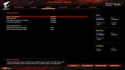
& IPSEC Certificate Enables or disables the Internet Protocol Security. This item is configurable only when Network Stack is enabled. & PXE boot wait time Allows you to configure how long to wait before you can press <Esc> to abort the PXE boot. This item is configurable only when Network Stack is enabled. -
Page 31
ƒ Smart Fan 5 & Monitor Allows you to select a target to monitor and to make further adjustment. (Default: CPU FAN) & Fan Speed Control Allows you to determine whether to enable the fan speed control function and adjust the fan speed. Normal Allows the fan to run at different speeds according to the temperature. -
Page 32: System Info
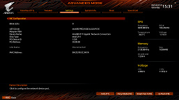
System Info. This section provides information on your motherboard model and BIOS version. You can also select the default language used by the BIOS and manually set the system time. & System Language Selects the default language used by the BIOS. &…
-
Page 33: Boot
A password is required for booting the system and for entering the BIOS Setup program. (Default) & Full Screen LOGO Show Allows you to determine whether to display the GIGABYTE Logo at system startup. Disabled skips the GIGABYTE Logo when the system starts up. (Default: Enabled) & Fast Boot Enables or disables Fast Boot to shorten the OS boot process.
-
Page 34
& NVMe Support Allows you to enable or disable NVMe device(s). (Default: Enabled) This item is configurable only when Fast Boot is set to Enabled or Ultra Fast. & VGA Support Allows you to select which type of operating system to boot. Auto Enables legacy option ROM only. -
Page 35
& Administrator Password Allows you to configure an administrator password. Press <Enter> on this item, type the password, and then press <Enter>. You will be requested to confirm the password. Type the password again and press <Enter>. You must enter the administrator password (or user password) at system startup and when entering BIOS Setup. -
Page 36: Save & Exit
Save & Exit & Save & Exit Setup Press <Enter> on this item and select Yes. This saves the changes to the CMOS and exits the BIOS Setup program. Select No or press <Esc> to return to the BIOS Setup Main Menu. &…
-
Page 37: Chapter 3 Appendix
Chapter 3 Appendix 3-1 Configuring a RAID Set RAID Levels RAID 0 RAID 1 RAID 10 ≥2 Minimum Number of Hard Drives Number of hard drives * Size of the smallest drive (Number of hard drives/2) * Array Capacity Size of the smallest drive Size of the smallest drive Fault Tolerance Before you begin, please prepare the following items:…
-
Page 38
4. Select AMD-RAID Bottom Device first and click Next to load the driver. Then select AMD-RAID Controller and click Next to load the driver. Finally, continue the OS installation. Please visit GIGABYTE’s website for details on configuring a RAID array. — 38 -… -
Page 39: Drivers Installation
You can click the Xpress Install button and «Xpress Install» will install all of the selected drivers. Or click the arrow icon to individually install the drivers you need. Please visit GIGABYTE’s website for more software information. Please visit GIGABYTE’s website for more troubleshooting information. — 39 -…
-
Page 40: Regulatory Statements
Contravention will be prosecuted. We believe that the information contained herein was accurate in all respects at the time of printing. GIGABYTE cannot, however, assume any responsibility for errors or omissions in this text. Also note that the information in this document is subject to change without notice and should not be construed as a commitment by GIGABYTE.
-
Page 41
FCC Notice (U.S.A. Only) Operation is subject to the following two conditions: (1) this device may not cause harmful interference, and (2) this device must accept any interference received, including interference that may cause undesired operation. WARNING: This equipment has been tested and found to comply with the limits for a Class B digital device, pursuant to Part 15 of the FCC Rules. -
Page 42
Canada-Industry Canada (IC): This device complies with Canadian RSS-210. This device complies with Industry Canada license-exempt RSS standard(s). Operation is subject to the following two conditions: (1) this device may not cause interference, and (2) this device must accept any interference, including interference that may cause undesired operation of the device. -
Page 43
European Community Radio Equipment Directive (RED) Compliance Statement: This equipment complies with all the requirements and other relevant provisions of Radio Equipment Directive 2014/53/EU. This equipment is suitable for home and office use in all the European Community Member States and EFTA Member States. -
Page 44: Contact Us
Contact Us GIGA-BYTE TECHNOLOGY CO., LTD. Address: No.6, Baoqiang Rd., Xindian Dist., New Taipei City 231, Taiwan TEL: +886-2-8912-4000, FAX: +886-2-8912-4005 Tech. and Non-Tech. Support (Sales/Marketing) : https://esupport.gigabyte.com WEB address (English): https://www.gigabyte.com WEB address (Chinese): https://www.gigabyte.com/tw • GIGABYTE eSupport To submit a technical or non-technical (Sales/Marketing) question, please link to: https://esupport.gigabyte.com…
инструкцияGigabyte X570 I AORUS PRO WIFI

To reduce the impacts on global warming, the packaging materials of this product
are recyclable and reusable. GIGABYTE works with you to protect the environment.
For more product details, please visit GIGABYTE’s website.
X570 I AORUS PRO
WIFI
User’s Manual
Rev. 1002
12ME-X57IAPW-1002R
Посмотреть инструкция для Gigabyte X570 I AORUS PRO WIFI бесплатно. Руководство относится к категории Материнские платы, 1 человек(а) дали ему среднюю оценку 7.5. Руководство доступно на следующих языках: английский. У вас есть вопрос о Gigabyte X570 I AORUS PRO WIFI или вам нужна помощь? Задайте свой вопрос здесь
- X570 I AORUS PRO WIFI Motherboard Layout
- Chapter 1 Hardware Installation
- Chapter 2 BIOS Setup
- Chapter 3 Appendix
Главная
| Gigabyte | |
| X570 I AORUS PRO WIFI | X570 I AORUS PRO WIFI | |
| Материнская плата | |
| 4719331806408, 0889523018040 | |
| английский | |
| Руководство пользователя (PDF), Инструкция по установке (PDF) |
Процессор
| Производитель процессора | AMD |
| Сокет процессора | Разъем AM4 |
| Совместимые серии процессоров | AMD Ryzen 3 2nd Gen, AMD Ryzen 3 3rd Gen, AMD Ryzen 5 2nd Gen, AMD Ryzen 5 3rd Gen, AMD Ryzen 7 2nd Gen, AMD Ryzen 7 3rd Gen, AMD Ryzen 9 3rd Gen |
Свойства
| Семейство чипсета материнской платы | AMD |
| Чипсет материнской платы | AMD X570 |
| Комплектующие для | ПК |
| Формат материнской платы | Mini ITX |
| Поддерживаемые операционные системы Windows | Да |
| Мониторинг состояния ПК | FAN, Temperature, Voltage |
| Аудио чип | Realtek ALC1220-VB |
| Выходные звуковые каналы | 7.1 канала |
Память
| Поддерживаемые типы памяти | DDR4-SDRAM |
| Количество слотов памяти | 2 |
| Каналы памяти | Dual-channel |
| Error-correcting code (ECC) | Да |
| без функции коррекции ошибок | Да |
| Поддерживаемые частоты памяти | 2133,2400,2667,2933,3200,3300,3333,3400,3466,3600,3733,3800,3866,4000,4133,4266,4300,4400 MHz |
| Максимальная внутренняя память | 64 GB |
| Небуферизованная память | Да |
Контроллеры хранения данных
| Поддерживаемые интерфейсы носителя | M.2, SATA III |
| Уровни RAID | 0, 1,10 |
Графический адаптер
| Максимальное разрешение | 4096 x 2304 пикселей |
| HDCP | Да |
| Количество поддерживаемых дисплеев | 3 |
| Поддержка выделеной видео карты | Да |
| Поддержка технологии параллельной обработки | — |
Слоты расширения
| Количество M.2 (M) слотов | 2 |
| PCI Express x16 слоты | 1 |
Внутренние порты
| Разъемы USB 2.0 | 1 |
| Разъемы USB 3.2 Gen 1 (3.1 Gen 1) | 1 |
| Разъемы USB 3.2 Gen 2 (3.1 Gen 2) | 0 |
| Количество разъемов SATA III | 4 |
| Количество разъемов SATA II | 0 |
| Количество параллельных разъемов ATA (PATA) | 0 |
| Аудиоразъем передней панели | Да |
| Разъем передней панели | Да |
| Разъем питания ATX (24-конт.) | Да |
| Разъем вентилятора центрального процессора | Да |
| Количество разъемов вентилятора корпуса | 2 |
| TPM коннектор | Да |
| 12В разъем питания | Да |
| RGB LED контактный разъем | Да |
Порты на задней панели
| Количество портов USB 2.0 | 0 |
| Количество портов USB 3.2 Gen 1 (3.1 Gen 1) Type-A | 4 |
| Количество портов USB 3.2 Gen 1 (3.1 Gen 1) Type-С | 0 |
| Количество портов USB 3.2 Gen 2 (3.1 Gen 2) Type-A | 1 |
| Количество портов USB 3.2 Gen 2 (3.1 Gen 2) Type-С | 1 |
| Количество портов Ethernet LAN ( RJ-45) | 1 |
| Количество портов eSATA | 0 |
| Количество портов PS/2 | 0 |
| Порты FireWire | 0 |
| Количество портов VGA (D-Sub) | 0 |
| Количество HDMI портов | 2 |
| Версия HDMI | 2.0 |
| Количество портов DisplayPort | 1 |
| Версия DisplayPort | 1.2 |
| Линейные выходы наушников | 1 |
| Линейный вход микрофона | Да |
| Разъем антенны WiFi-AP | 2 |
Сеть
| Подключение Ethernet | Да |
| Тип Ethernet интерфейса | Fast Ethernet, Gigabit Ethernet |
| Wi-Fi | Да |
| Wi-Fi стандартов | 802.11a, 802.11b, 802.11g, Wi-Fi 4 (802.11n), Wi-Fi 5 (802.11ac), Wi-Fi 6 (802.11ax) |
| Bluetooth | Да |
| Версия Bluetooth | 5.0 |
BIOS
| Перемычка Clear CMOS | Да |
| Тип BIOS | UEFI AMI |
| Размер памяти BIOS | 128 Mbit |
| Версия ACPI | 5.0 |
| Desktop Management Interface (DMI) версия | 2.7 |
| Версия BIOS (SMBIOS) | 2.7 |
Вес и размеры
| Ширина | 170 mm |
| Глубина | 170 mm |
Содержимое упаковки
| Поставляемое ПО | Norton® Internet Security (OEM version)ncFosSpeednXSplit Gamecaster + Broadcaster (12 months license) |
Логистические данные
| Код гармонизированной системы описания (HS) | 84733020 |
показать больше
Не можете найти ответ на свой вопрос в руководстве? Вы можете найти ответ на свой вопрос ниже, в разделе часто задаваемых вопросов о Gigabyte X570 I AORUS PRO WIFI.
Какая ширина Gigabyte X570 I AORUS PRO WIFI?
Какая толщина Gigabyte X570 I AORUS PRO WIFI?
Инструкция Gigabyte X570 I AORUS PRO WIFI доступно в русский?
Не нашли свой вопрос? Задайте свой вопрос здесь
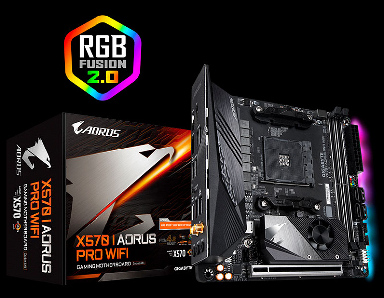
В начале августа мы тестировали суперплату Gigabyte X570 Aorus Xtreme на основе набора системной логики AMD X570. Данная модель может похвастать не только беспрецедентными возможностями для разгона процессоров или создания самых производительных систем, но и очень высокой стоимостью (около 60 тысяч рублей). Как оказалось, компания Gigabyte готова предложить очень многое из того, что есть в X570 Aorus Xtreme, почти в четыре раза дешевле, да еще и в компактном формате Mini-ITX. Вы думаете, мы шутим? Отнюдь! Встречайте: Gigabyte Aorus X570 I Pro WiFi.
Технические характеристики и стоимость
| Процессорный разъем | Socket AM4 |
|---|---|
| Поддерживаемые процессоры | AMD Ryzen 2-го и 3-го поколений |
| Чипсет | AMD X570 |
| Память | 2×DDR4, до 64 ГБ, до DDR4-4400 МГц на AMD Ryzen 3000 и до 3600 МГц на AMD Ryzen 2000 двухканальный режим работы модулей ОЗУ поддержка ECC-модулей DIMM 1Rx8/2Rx8 без буферизации поддержка non-ECC DIMM-модулей без буферизации 1Rx8/2Rx8/1Rx16 поддержка XMP-профилей модулей памяти (Extreme Memory Profile) |
| Слоты расширения | 1×PCI Express 4.0 x16 на AMD Ryzen 3000 или 3.0 х16 AMD Ryzen 2000 |
| Разъемы для накопителей | 4×SATA 6 Гбит/с (поддержка дисковых массивов RAID 0, RAID 1, и RAID 10) 1×M.2A (CPU, PCI-E 4.0/3.0 x4/SATA 6 Гбит/с для устройств формата 2260/2280) 1×M.2B (X570, PCI-E 4.0/3.0 x4/SATA 6 Гбит/с для устройств формата 2260/2280) |
| Сетевые контроллеры | Intel Ethernet Connection I211-AT (10/100/1000 Мбит/с, поддержка cFosSpeed) модуль Intel AX200NGW (Wi-Fi 6 802.11a/b/g/n/ac/ax, поддержка диапазонов 2,4/5 ГГц) модуль Bluetooth 5.0 поддерживается стандарт беспроводной связи 11ax 160 МГц и скорость передачи данных до 2,4 Гбит/с |
| Аудиоподсистема | Realtek ALC1220-VB + конденсаторы Nichicon (3 шт. 100 мкФ, 6,3 В) |
| USB-порты | 1×USB 3.2 Gen2 (Type-C на задней панели, X570) 1×USB 3.2 Gen2 (Type-A на задней панели, X570) 4×USB 3.2 Gen1 (на задней панели, CPU) 2×USB 3.2 Gen1 (доступны с внутреннего коннектора, X570) 2×USB 2.0 (доступны с внутреннего коннектора, X570) |
| Разъемы на задней панели | DisplayPort и HDMI 2×USB 3.2 Gen1 и HDMI 2×USB 3.2 Gen1 кнопка Q-Flash Plus 1×RJ-45 и 2×USB 3.2 Gen2 (Type-C и Type-A) 2 разъема SMA для подключения антенн (2T2R) 3 разъема аудиоподсистемы |
| Прочие внутренние разъемы | 24-контактный разъем питания ATX 8-контактный разъем питания ATX 12V разъем для подключения вентилятора системы охлаждения CPU разъем для подключения корпусного вентилятора разъем для подключения RGB LED-линеек разъем для подключения адресуемых RGB LED-линеек 4 разъема SATA 6 Гбит/с 2 разъема M.2 Socket 3 группа разъемов для передней панели корпуса группа аудиоразъемов для передней панели корпуса разъем для подключения динамика разъем для подключения 2 портов USB 2.0 разъем для подключения 2 портов USB 3.2 Gen1 разъем TPM-модуля (Trusted Platform Module) перемычка сброса CMOS |
| Форм-фактор | Mini-ITX (170×170 мм) |
| Розничные предложения |
узнать цену |
Упаковка и комплектация
Gigabyte Aorus X570 I Pro WiFi поставляется в компактной коробке, на лицевой стороне которой приведено название платы и основные ее особенности.
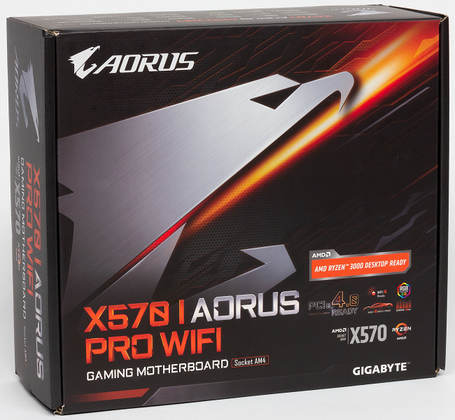
На обратной стороне коробки можно найти краткие технические характеристики, перечисление основных достоинств продукта и схематичное изображение портов на интерфейсной панели.

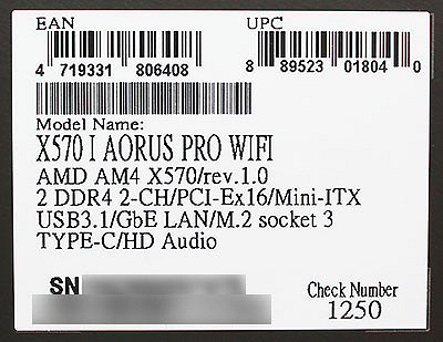
Небольшая наклейка со штрихкодами на торце коробки содержит краткое перечисление характеристик платы и ее серийный номер.
Внутри в коробке два отсека. Верхний занимает плата, упакованная в антистатический пакет и лежащая в мягкой оболочке из вспененного полиэтилена. Можно сказать, что это весьма неплохая защита, что немаловажно, поскольку только за прошедший месяц я получил на тестирование две комплектующих с пробитыми коробками. И пусть само устройство пострадало только в одном случае, дополнительная страховка в виде таких вот мягких оболочек не помешает.
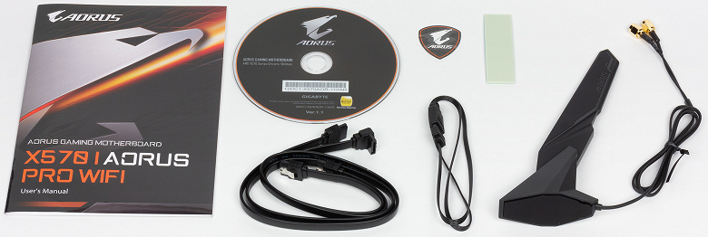
Нижнюю часть коробки занимают комплектующие. В их числе два SATA-кабеля, кабель для подсветки, антенна модуля беспроводной связи, наклейка с логотипом Aorus, диск с драйверами и инструкция.
Плата производится на Тайване и обеспечивается трехлетней гарантией. Gigabyte Aorus X570 I Pro WiFi уже поступила в продажу в российские магазины, где ее можно приобрести по цене от 16 тысяч рублей.
Дизайн и особенности
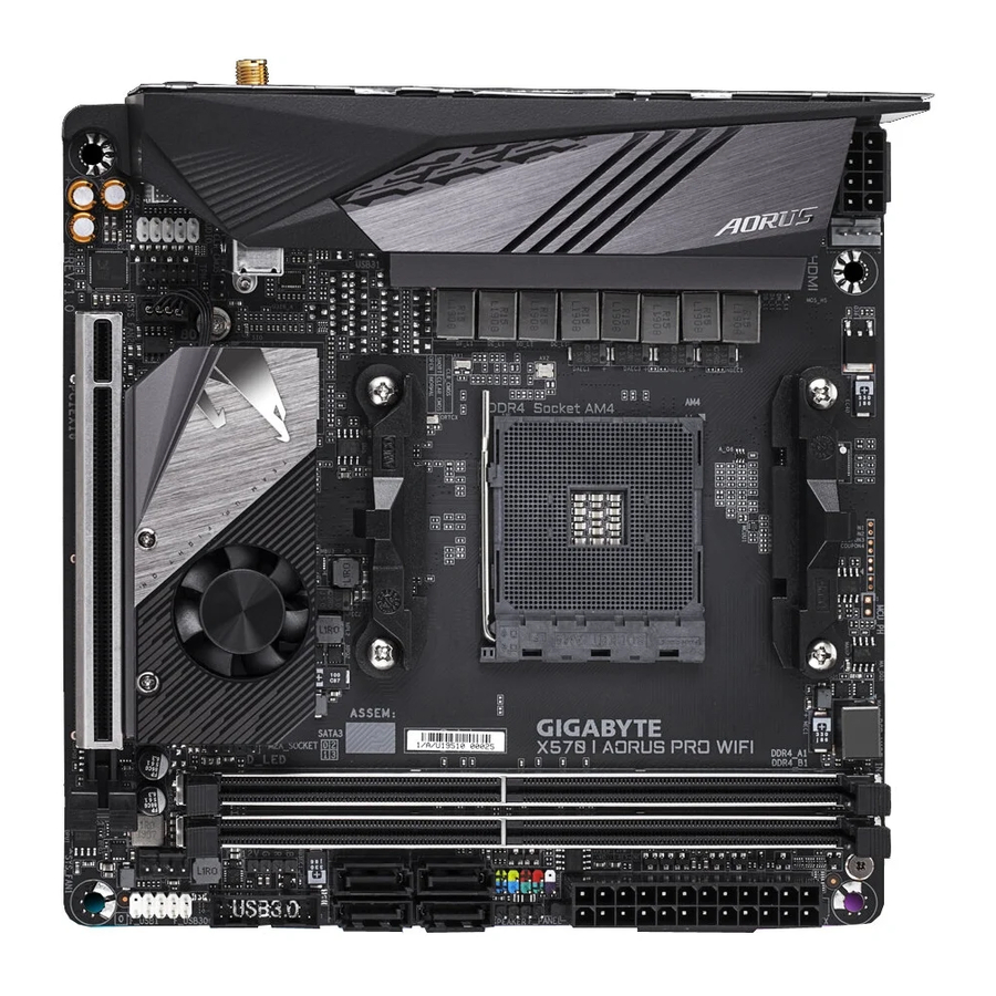
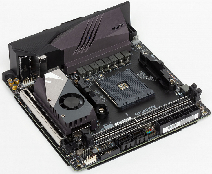
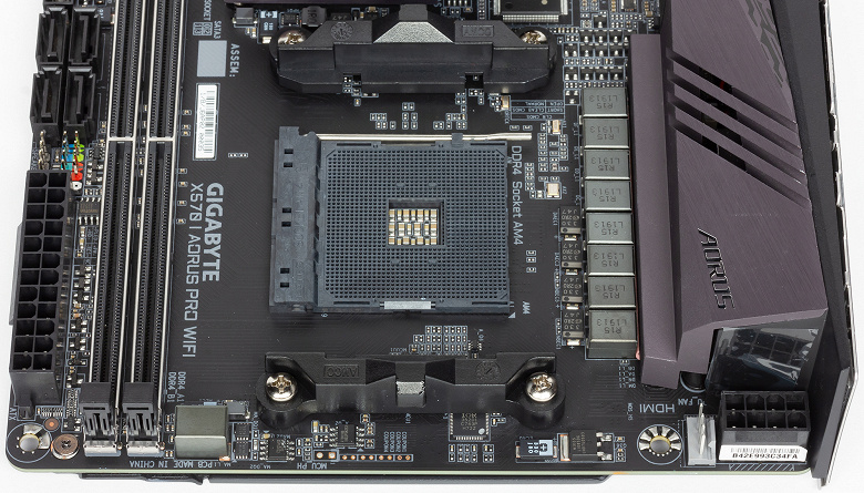
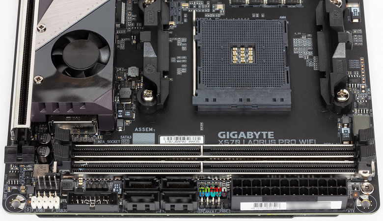
Gigabyte Aorus X570 I Pro WiFi — компактная плата формата Mini-ITX, оформленная в темных тонах. Она имеет плотную компоновку, когда все элементы размещены в непосредственной близости друг к другу, а радиатор силовой цепи питания процессора интегрирован в кожух интерфейсной панели платы.
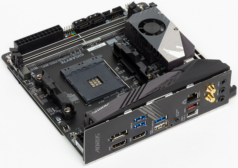
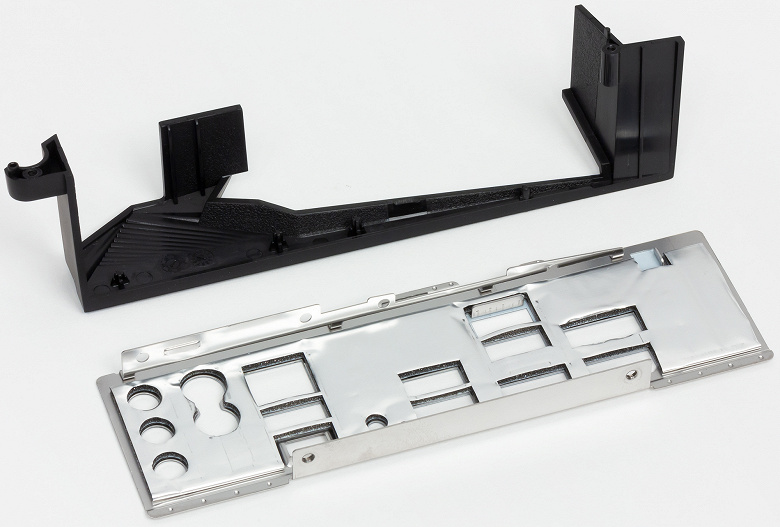
Сама панель здесь идет сразу встроенная в порты, что облегчает установку такой маленькой платы в корпус системного блока.
Среди основных достоинств новой Gigabyte Aorus X570 I Pro WiFi, приведенных на фото ниже, можно выделить восьмислойную печатную плату с восьмифазной же системой питания процессора, два разъема M.2 и разъем PCI Express версии 4.0, два сетевых контроллера и подсветку.
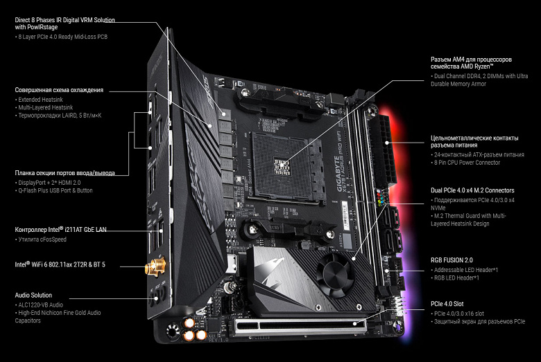
Детальное расположение элементов и контроллеров платы приведено на схеме из инструкции по эксплуатации.
На панели ввода/вывода платы размещено три видеовыхода, 6 портов USB, включая два высокоскоростных USB 3.2 Gen2, сетевая розетка RJ-45 и разъемы для подключения беспроводной антенны, три аудиовыхода и кнопка Q-Flash plus.
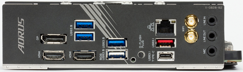
Если плата будет размещена на тестовом стенде, то промаркированные порты можно считать удобством, а когда она будет установлена в корпус системного блока, то особого значения данный факт уже иметь не будет. Добавим, что интерфейсная панель снимается вместе с пластиковой накладкой.
Поскольку в формате Mini-ITX есть только 289 см² площади, то плотность элементов и разъемов на лицевой стороне очень высокая.
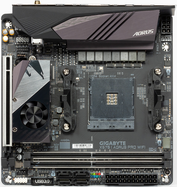
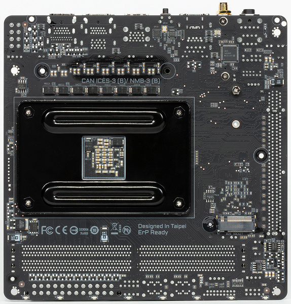
И это несмотря на тот факт, что некоторые микросхемы, контроллеры и разъемы вынесены на обратную сторону текстолита, дополнительно защищенную металлической пластиной.
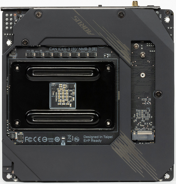
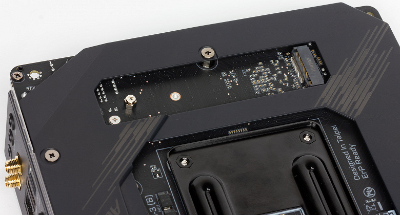
Удобно, что место под размещение накопителя в порт M.2 не закрыто данной пластиной, что не только позволит устанавливать и вынимать накопитель без демонтажа платы из корпуса системного блока (без вырезов в поддоне мы корпусов уже несколько лет не встречали), но и оснастить накопитель радиатором для его более эффективного охлаждения.
Винтовое крепление всех радиаторов и навесных элементов платы позволяет быстро и аккуратно снять с нее радиаторы и кожух, чтобы предметно изучить все компоненты.
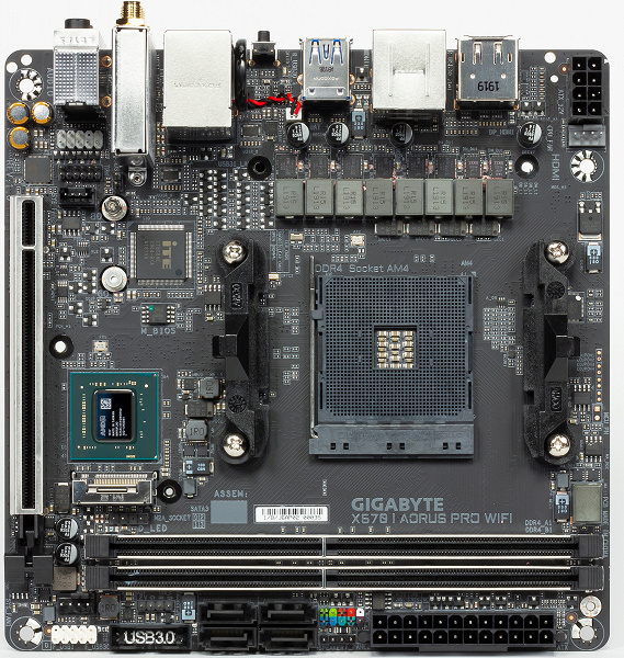
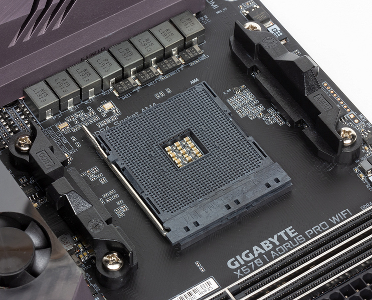
Gigabyte Aorus X570 I Pro WiFi оснащается стандартным разъемом Socket AM4 и поддерживает все процессоры AMD Ryzen второго и третьего поколений. Еще одним плюсом такого подхода к процессорным разъемам AMD является совместимость с существующими системами охлаждения CPU.
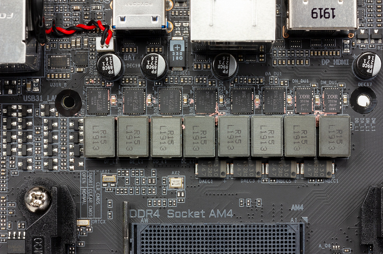
В системе питания платы используются восемь честных фаз (без дублеров), скомпонованные из шести Infineon TDA21472 Power Stage (70 A) для ядра процессора и двух IR3553 (40 A) для SoC.
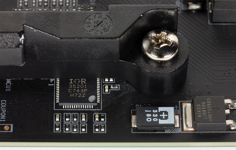
За управление питанием процессора отвечает восьмиканальный PWM-контроллер IR 35201.
Видеть подобную систему питания процессора на плате формата Mini-ITX весьма необычно и в то же время приятно, поскольку ее с запасом хватит для любых вышедших процессоров AMD Ryzen 3000 как в номинальном режиме работы, так и при разгоне.
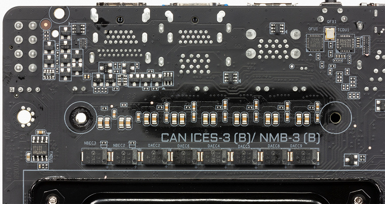
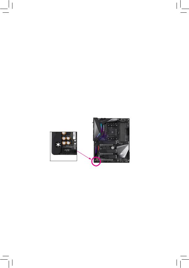
На плате используются два разъема питания с 24 и 8 контактами, но восьмиконтактный разъем расположен в самом углу и в непосредственной близости к интерфейсной панели, поэтому подключать и отключать от него кабель мы рекомендуем до установки платы в посадочное место корпуса.
Отметим, что контактные иглы внутри разъемов питания платы цельнометаллические и повышенной плотности, поэтому они долговечнее и надежнее обычных полых игл.
В основе материнской платы лежит новый набор системной логики AMD X570. Кристалл чипсета контактирует со своим небольшим радиатором через сухой термоинтерфейс серого цвета.
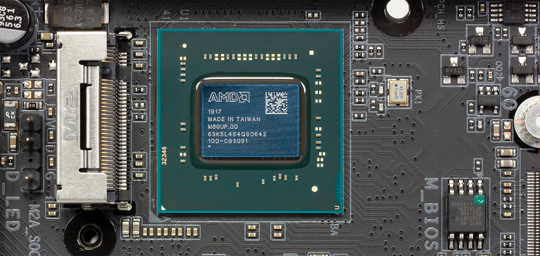
Кстати, в процессе работы чипсет довольно серьезно греется, вплоть до 65 °C.
Плата оснащена двумя слотами DIMM оперативной памяти, облаченными в металлизированную оболочку Ultra Durable Memory Armor. Последняя не только усиливает сами разъемы, но и защищает контакты в них от электромагнитных помех.
На Gigabyte Aorus X570 I Pro WiFi можно установить два DDR4-модуля суммарным объемом 64 ГБ с частотами от 2133 до 4400 МГц при использовании процессоров AMD Ryzen третьего поколения и до 3600 МГц при использовании процессоров второго поколения. Поддерживаются XMP (Extreme Memory Profile) и огромный перечень сертифицированных для данной модели платы комплектов памяти.
Слот PCI Express на плате всего один, но он также имеет оболочку Ultra Durable, усиливающую его на излом в 1,7 раза и на выдергивание в 3,2 раза.
Слот PCI Express поддерживает работу в режиме 4.0 x16 (31,5 Гбит/с) с процессорами AMD Ryzen 3000 и в режиме 3.0 х16 (15,8 Гбит/с) с AMD Ryzen 2000.
Для накопителей плата имеет четыре порта SATA600 с пропускной способностью до 6 Гбит/с, которые реализованы возможностями чипсета AMD X570 и расположены в вертикальной ориентации. Поддерживается создание массивов RAID уровней 0, 1 и 10. Поддержку высокоскоростных накопителей SSD на данной модели платы реализовали двумя портами M.2, совместимыми, как с SATA-, так и PCI Express-устройствами длиной 60 или 80 мм. M.2A расположен на обратной стороне текстолита и подключен к процессору, а M.2B размещен под радиатором и вентилятором чипсета, к которому он и подключен.
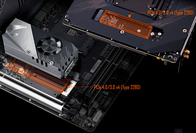
Интересно, что из двух одинаковых накопителей в этих портах можно организовать RAID 0, достигнув очень высоких скоростей чтения и записи.
Несмотря на компактные размеры, Gigabyte Aorus X570 I Pro WiFi оснастили десятью портами USB. Два скоростных порта USB 3.2 Gen2 (Type-A и Type-C) реализованы набором системной логики AMD X570 и выведены на заднюю панель платы. Там же можно найти четыре USB 3.2 Gen1, реализованные процессорными линиями. Еще две пары портов USB 3.2 Gen1 и USB 2.0 можно подключить к коннекторам на текстолите. За их работу отвечает чипсет AMD X570.
Кабельная сеть на плате реализована контроллером Intel Ethernet Connection I211-AT
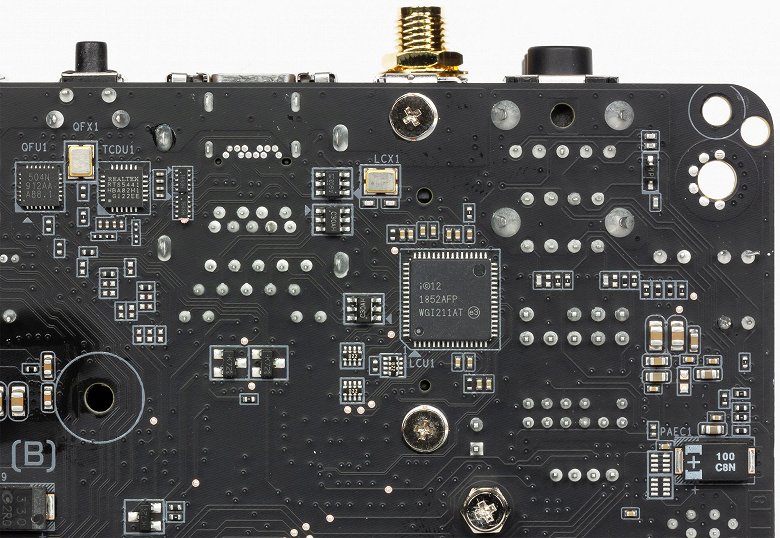
Он поддерживает технологию приоритезации трафика cFosSpeed, уменьшающую задержки и снижающую время отклика.
Беспроводная связь реализована контроллером Intel AX200NGW, установленным в слот M.2 (E-key) с выведенными коннекторами для антенн на заднюю панель.
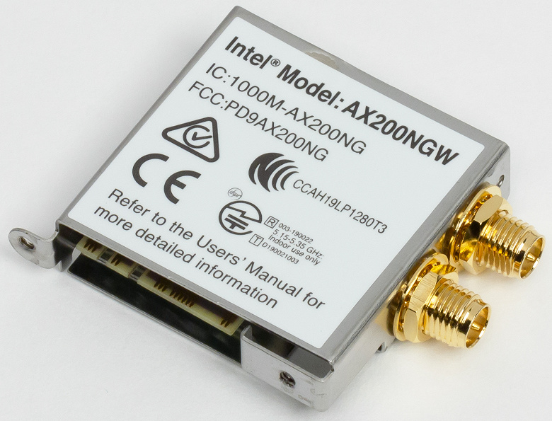
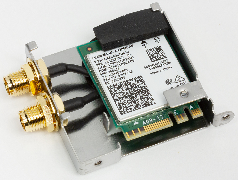
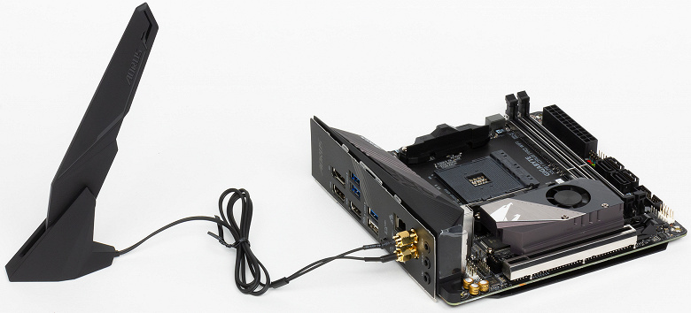
Контроллером поддерживаются высокоскоростные стандарты связи WiFi 6 (802.11ax) и Bluetooth 5.0.
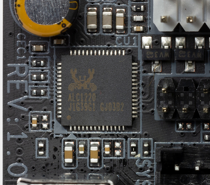
Звуковой тракт платы основан на 7.1-канальном HDA-аудиокодеке Realtek ALC1220-VB в паре с интеллектуальным усилителем для наушников. Компанию им составляют три «аудиофильских» конденсатора Nichicon японского производства (100 мкФ, 6,3 В).
Реализация функций Super I/O и мониторинга на Gigabyte Aorus X570 I Pro WiFi выполнена с помощью контроллера iTE IT8688E.
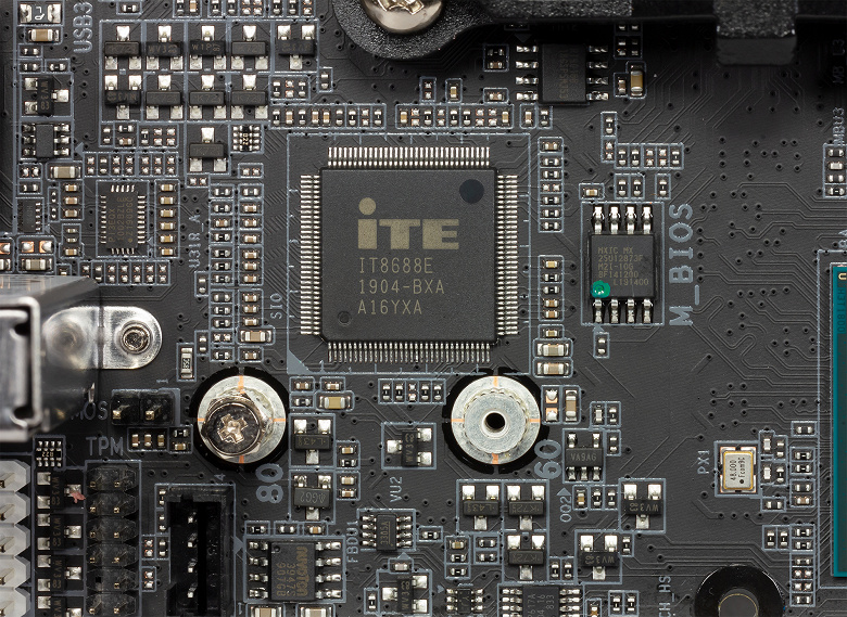
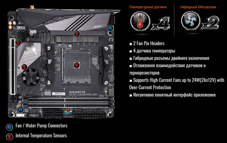
Данный контроллер используется и на других платах Gigabyte и имеет достаточно широкие возможности, но ввиду компактности платы на ней есть только четыре термодатчика и два разъема для вентиляторов с поддержкой ШИМ-управления.
Есть у малютки Gigabyte Aorus X570 I Pro WiFi и подсветка. На самом текстолите с обратной его стороны встроена линейка светодиодов, а на лицевой есть два разъема для обычных и адресуемых лент светодиодной подсветки.
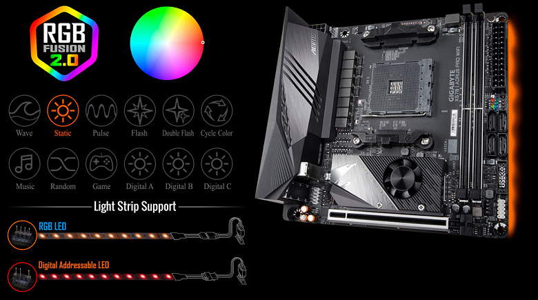
Управление подсветкой платы и подключенной к ней RGB-ленты осуществляется через приложение Gigabyte RGB Fusion.
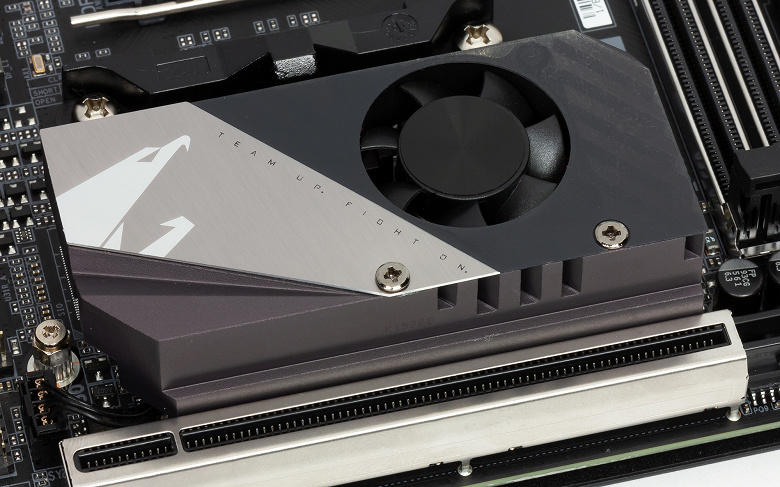
В системе охлаждения Gigabyte Aorus X570 I Pro WiFi используются три радиатора и один маленький вентилятор 30 мм.
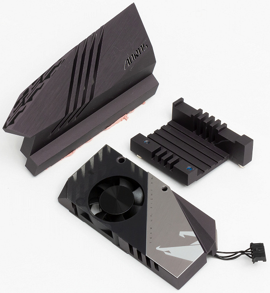
Самый массивный радиатор установлен на силовых цепях питания процессора, с которыми контактирует через термопрокладку. Над чипсетом размещен маленький радиатор, охлаждаемый малюсеньким вентилятором модели Everflow R123510BM, скорость которого может достигать 7500 об/мин, но в наших тестах она не превышала 3600 об/мин.
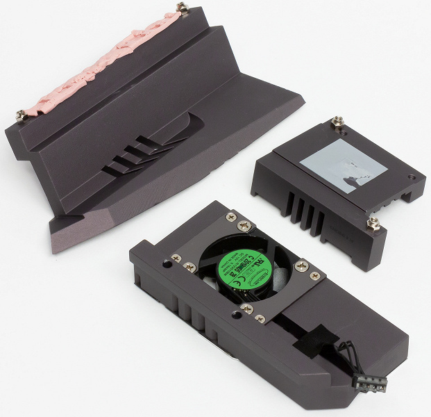
Однако самым необычным моментом в системе охлаждения является тот факт, что между радиатором чипсета AMF X570 и вентилятором в порт M.2 может устанавливаться SSD-накопитель. Забегая вперед скажем, что по датчику мониторинга температура чипсета без накопителя достигает 65 °C, поэтому остается только догадываться, как сильно будет нагреваться чипсет, если над ним еще и разместится SSD, и что будет происходить с производительностью самого накопителя. Благо, приоритетным для использования является порт M.2 на обратной стороне платы, а два SSD-накопителя в портах M.2 пока еще редко встречаются в домашних системах.
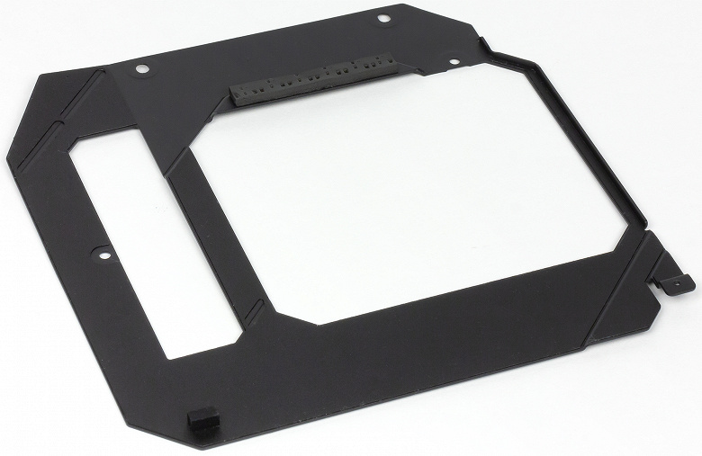
Добавим, что металлическая пластина на обратной стороне платы выполняет не только защитную и декоративную функцию, поскольку через толстую термопрокладку она контактирует с зоной силовых ключей.
Возможности UEFI BIOS
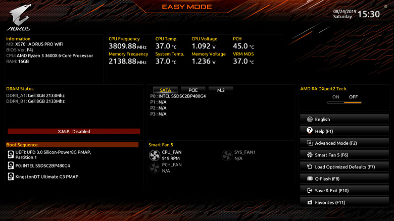
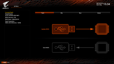
Перед тестированием мы прошили Gigabyte Aorus X570 I Pro WiFi последнюю доступную версию BIOS F4j от 2 августа текущего года. Плата стартует в упрощенном режиме BIOS Easy Mode, где для настройки доступны базовые параметры и основные показатели мониторинга.
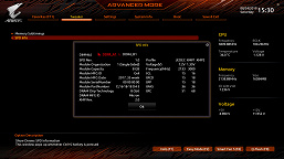
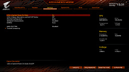
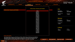
Переключение в классический режим BIOS традиционно происходит при нажатии на F2. Здесь мы видим пять основных разделов с настройками и раздел с избранными настройками. В наиболее функциональном разделе Tweaker можно регулировать частоту (100—119 МГц) и множитель (8—63,75) процессора, задействовать XMP оперативной памяти, а также отъюстировать основные напряжения.
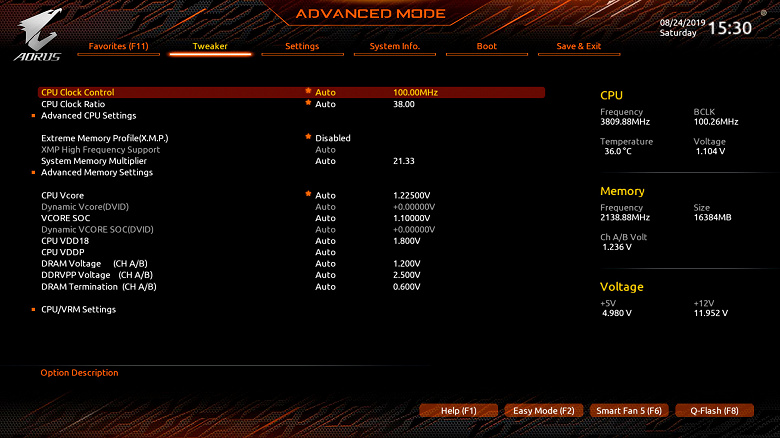
Для процессора, оперативной памяти и VRM в этом разделе есть дополнительные подразделы, касающиеся тонких настроек каждого компонента платы.
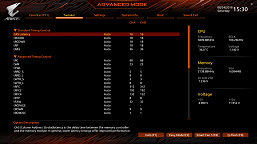
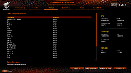
Традиционно широки настройки таймингов оперативной памяти и очень удобно выводится информация из ее SPD.
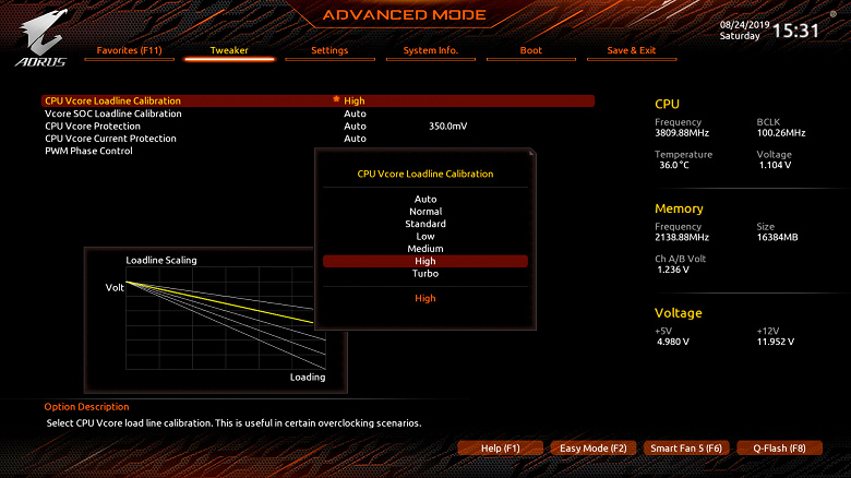
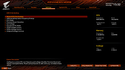
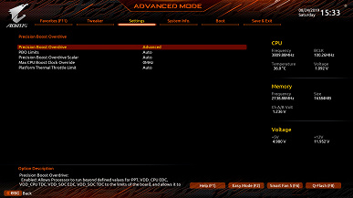
Для процессора в BIOS предусмотрены семь уровней стабилизации напряжения (LLC), при выборе каждого из которых на графике показывается, в какой степени напряжение CPU будет стабилизировано.
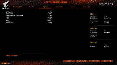
Доступных для изменения напряжений у платы Gigabyte Aorus X570 I Pro WiFi более чем достаточно. Приведем их в таблице.
| Напряжение | Минимальное значение, В | Максимальное значение, В | Шаг |
|---|---|---|---|
| CPU Vcore | 0,7500 | 1,8000 | 0,00625 |
| Dynamic Vcore | –0,3000 | +0,3000 | 0,00625 |
| Vcore SOC | 0,7500 | 1,8000 | 0,00625 |
| Dynamic Vcore SOC | –0,3000 | +0,3000 | 0,00625 |
| CPU VDD18 | 1,6000 | 2,3200 | 0,040 |
| CPU VDDP | –0,2000 | +0,7000 | 0,020 |
| DRAM | 1,000 | 2,000 | 0,010 |
| DRAM VPP | 1,980 | 3,020 | 0,040 |
| DRAM Termination | 0,375 | 0,833 | 0,004 |
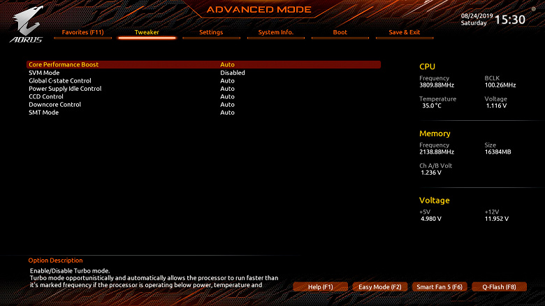
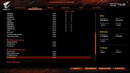
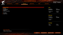
В основном разделе Settings собраны настройки контроллеров и периферийных устройств, а также тонкие настройки AMD Ryzen.
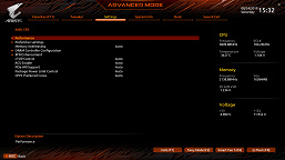
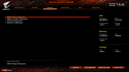
Здесь же расположен подраздел с мониторингом всех напряжений в реальном времени.
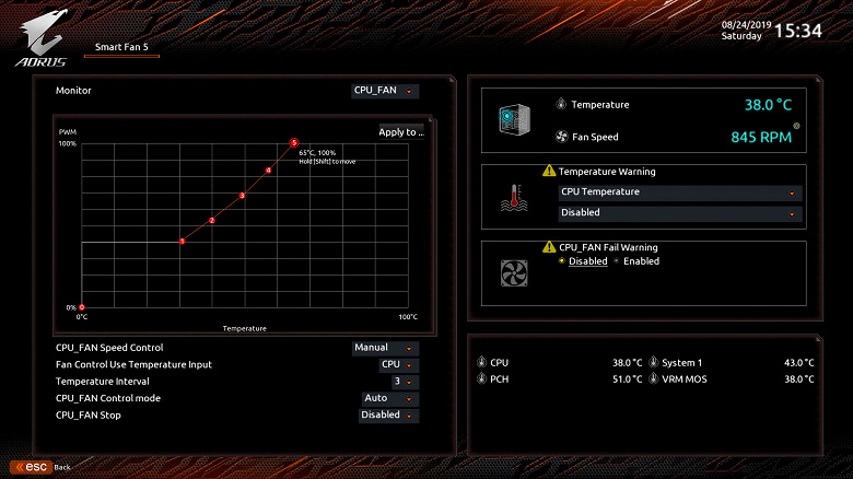
Встроенная в BIOS утилита Smart Fan 5 быстро и легко поможет настроить оба подключенных к плате вентилятора, а также вентилятор чипсета.
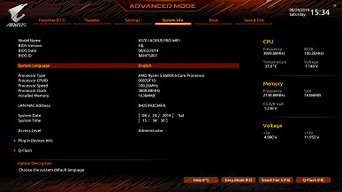
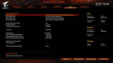
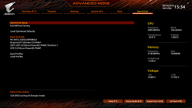
Остались разделы с информацией о системе, параметрами загрузки и встроенная утилита для обновления BIOS.
Отметим, что при работе в BIOS никаких проблем у нас не возникло. Скорость отклика оболочки очень высокая, а при выходе из BIOS отображаются все измененные настройки, чтобы их можно было еще раз перепроверить.
Разгон и стабильность
Проверка стабильности, оверклокерского потенциала и производительности материнской платы Gigabyte Aorus X570 I Pro WiFi была проведена в закрытом корпусе системного блока при температуре в помещении около 26 °C. Конфигурация тестового стенда состояла из следующих комплектующих:
- системная плата: Gigabyte Aorus X570 I Pro WiFi (AMD X570, Socket AM4, BIOS F4j от 02.08.2019);
- процессор: AMD Ryzen 5 3600X (Matisse, 7 нм, B0, 3,8 (4,4) ГГц, 6×512 КБ L2, 32 МБ L3, TDP 95 Вт);
- система охлаждения CPU: Noctua NH-D15 (один вентилятор 140 мм Noctua NF-A15 на 740—1530 об/мин);
- термоинтерфейс: Arctic MX-4;
- оперативная память: DDR4 2×8 ГБ GeIL Super Luce RGB (GLS416GB3000C16ADC), XMP 3000 МГц 16-18-18-36 CR2 при 1,35 В;
- видеокарта: Nvidia GeForce RTX 2080 Founders Edition 8 ГБ/256 бит, 1515—1800(1965)/14000 МГц;
- системный диск: Intel SSD 730 480 ГБ (SATA600, BIOS vL2010400);
- диск для программ и игр: Western Digital VelociRaptor 300 ГБ (SATA300, 10000 об/мин, 16 МБ, NCQ);
- архивный диск: Samsung Ecogreen F4 HD204UI 2 ТБ (SATA300, 5400 об/мин, 32 МБ, NCQ);
- корпус: Thermaltake Core X71 (шесть be quiet! Silent Wings 2 [BL063] на 900 об/мин, три — на вдув, три — на выдув);
- панель управления и мониторинга: Zalman ZM-MFC3;
- блок питания: Corsair AX1500i Digital ATX (1500 Вт, 80 Plus Titanium), вентилятор 140 мм.
Тестирование было проведено под управлением операционной системы Microsoft Windows 10 Pro (1903 18362.295) с установкой следующих драйверов:
- для чипсета материнской платы: AMD Chipset Drivers 1.8.19.0915 от 20.08.2019
- для видеокарты: Nvidia GeForce 431.68 WHQL от 26.07.2019
Стабильность системы в номинальном режиме и при разгоне мы проверяли стресс-утилитой Prime95 29.8 build 5 и другими бенчмарками, а мониторинг проводился с помощью HWiNFO64 версии 6.11-3895.
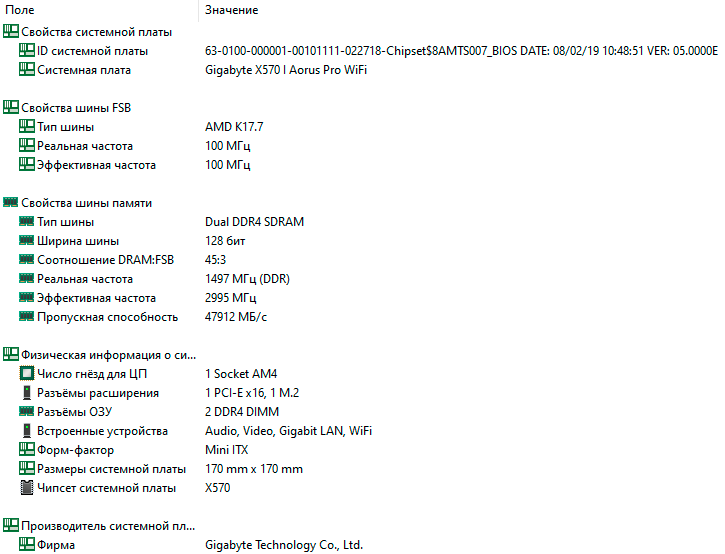
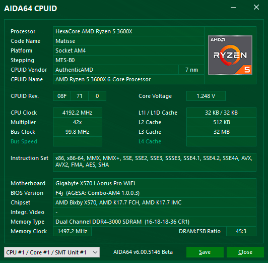
Сначала приведем характеристики платы Gigabyte Aorus X570 I Pro WiFi с помощью информационно-диагностической утилиты AIDA64 Extreme.
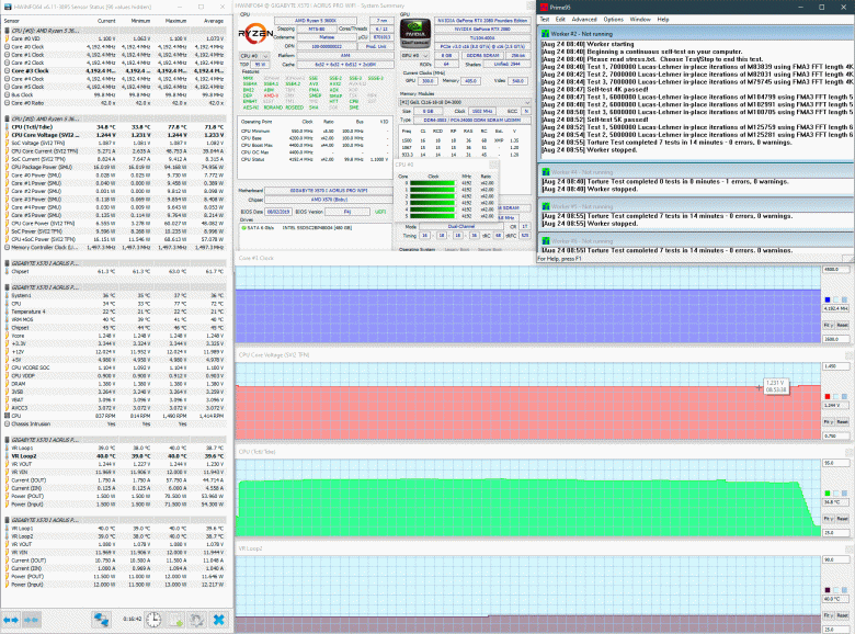
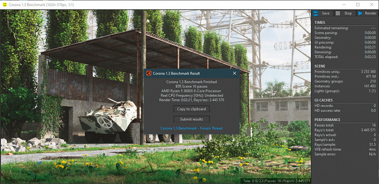
Активировав XMP оперативной памяти, мы провели тестирование собранной системы при настройках BIOS платы по умолчанию (LLC — auto).

Процессор работал на частотах от 3,0 до 4,37 ГГц при пиковом напряжении 1,452 В. В нагрузке частота процессора держалась у отметки 4,1 ГГц, а напряжение — у 1,30-1,31 В.
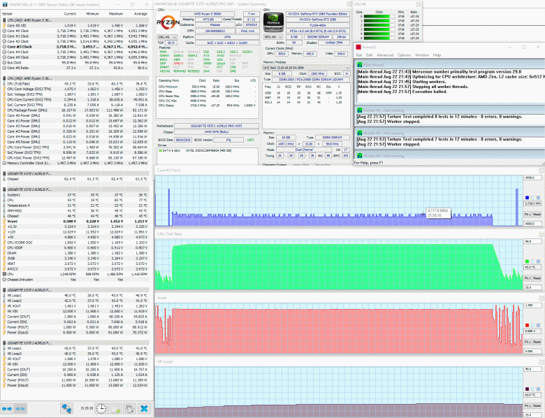
При этом температуры у нас вызвали определенное беспокойство. Максимальная температура процессора слегка превысила 83 °C, VRM цепей поднялась до 45 градусов, а чипсет функционировал на 62,4 градусах, вообще не опускаясь ниже 61. И это в огромном хорошо продуваемом корпусе с шестью вентиляторами 140 мм и суперкулере на процессоре (пусть и с одним вентилятором). Не трудно предположить, что в корпусах формата Mini-ITX, для которых и предназначена такая плата, температуры будут выше, а значит ресурс основных компонентов в какой-то степени сократится.
В попытках как-то урегулировать ситуацию с температурами, мы протестировали с помощью Prime95 все возможные уровни стабилизации напряжения на ядре процессора (LLC) в BIOS материнской платы, и вот какие данные получили:
| Уровень LLC | Частота CPU при нагрузке, ГГц | Напряжение CPU при нагрузке, B | Максимальная температура CPU, °C | Максимальная температура VRM, °C |
|---|---|---|---|---|
| Normal | 4,125 | 1,305 | 84 | 43 |
| Standard | 4,085 | 1,285 | 84 | 45 |
| Low | 4,085 | 1,300 | 89,3 | 45 |
| Medium | 4,100 | 1,316 | 89,5 | 46 |
| High | 4,100 | 1,325 | 89,8 | 47 |
| Turbo | 4,060 | 1,335 | 91,4 | 47 |
Как видим, с процессором AMD Ryzen 5 3600X каких-то результатов по снижению температур в сравнении с автоматическим режимом стабилизации добиться не удалось. Лучшие показатели демонстрируют уровни Normal и Standard, тогда как другие уровни LLC приводят лишь к росту температуры и напряжения, и даже снижению средней частоты процессора при нагрузке (что как раз является следствием повышения температуры). Однако с другими процессорами ситуация может быть иной.
Еще одним вариантом борьбы с высокими температурами является фиксация частоты процессора и подбор минимально возможного напряжения, при котором производительность процессора AMD Ryzen 5 3600X не снижалась. Здесь нам удалось добиться определенного успеха, определив после нескольких часов тестов, что наш экземпляр AMD Ryzen 5 3600X при множителе 42 по всем ядрам и LLC Standard стабилен при напряжении 1,25 В.
Температура процессора при этом не превысила отметку 78 °C, а температура VRM MOS — 41 градуса.
Правда, одну ошибку по одному ядру все же удалось поймать, но в целом система была стабильна. Конечно, производительность на одно ядро в данном случае слегка пострадала, зато немного выросла производительность в многопоточных задачах, но главное, что снизились температуры.
В плане разгона новые процессора AMD Ryzen третьего поколения не радуют оверклокеров и наш экземпляр, к сожалению, не является исключением. Максимум, чего удалось добиться, это 4,25 ГГц при напряжении 1,33125 В и уровне LLC High.
Температура процессора с таким «разгоном» достигла 92 °C, а по производительности добавились сущие крохи.
Остается дополнить, что наш комплект оперативной памяти GeIL Super Luce RGB объемом два по восемь гигабайт даже на платформе Intel практически не разгоняется (максимум 3,2 ГГц), а на данной плате даже этой отметки не смог достичь. Впрочем, это проблема исключительно данного комплекта памяти, а не материнской платы.
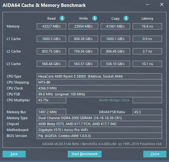
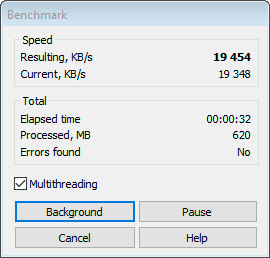
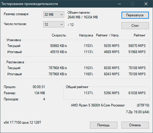
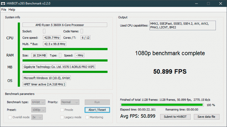
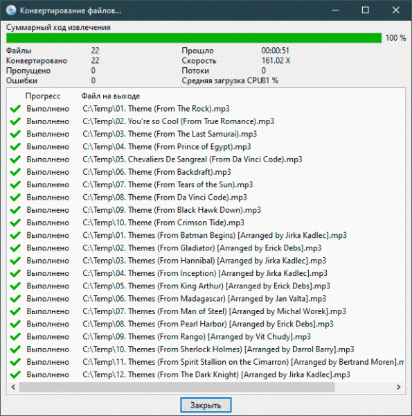
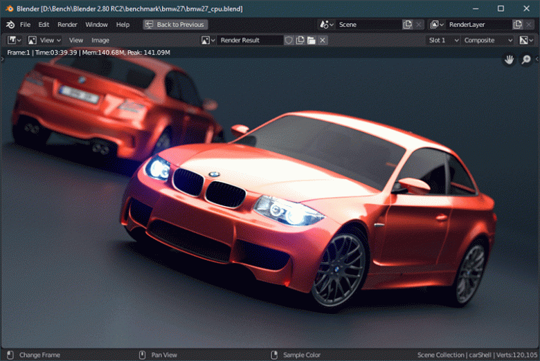
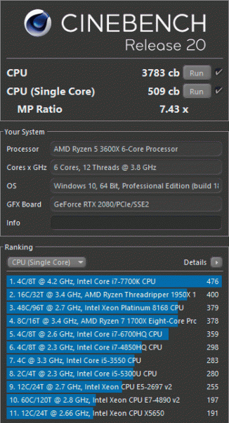
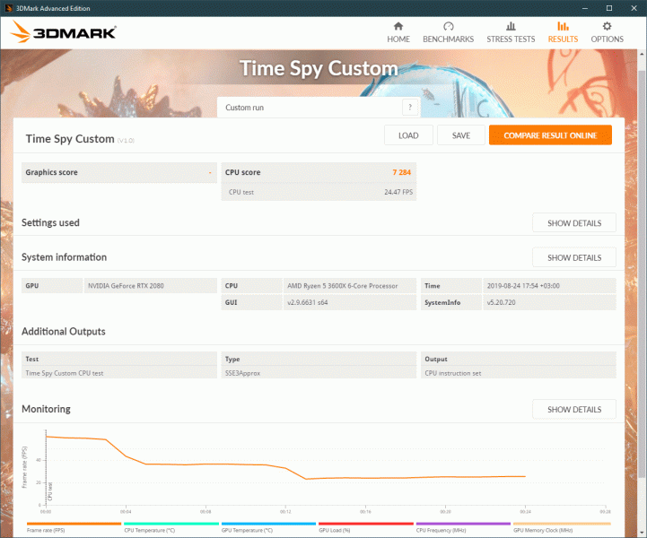
Производительность
Напоследок, мы протестировали Gigabyte Aorus X570 I Pro WiFi в нескольких бенчмарках.
Заключение
В формате Mini-ITX плата Gigabyte Aorus X570 I Pro WiFi предоставляет максимум возможностей для создания домашней системы любого уровня. Этому способствуют возможность установки любых актуальных процессоров AMD Ryzen, поддержка 64 ГБ оперативной памяти с частотами до 4,4 ГГц и нового интерфейса PCI Express 4.0, пара высокоскоростных M.2 с возможностью работы в RAID 0, два сетевых контроллера (включая беспроводной Wi-Fi 6), десять портов USB, очень приличный звук и подсветка, в том числе возможность подключения двух RGB-лент. Функциональный BIOS платы имеет массу как рядовых настроек, так и настроек для оверклокинга.
В то же время, из-за компактности платы у нее есть несколько проблемных моментов. Самый главный, на наш взгляд, это размещение накопителя во втором слоте M.2 над радиатором чипсета, который постоянно держит температуру не ниже 60 °C. То есть установка SSD в этот слот перекроет радиатор чипсета, который будет нагреваться еще сильнее и тем самым будет повышать температуру накопителя, а значит, и замедлять его работу. Кроме того, сам маленький вентилятор отчетливо слышно. Второй момент — это плотность расположения элементов и коннекторов на плате — подключать к ней кабели очень неудобно. Впрочем, это характерно для всех плат данного форм-фактора.
И все же в целом плата справляется со своими обязанностями, имеет мощную систему питания процессора, элементы которой эффективно охлаждаются в процессе работы и едва греются. Gigabyte Aorus X570 I Pro WiFi способна стать основой одновременно производительной и очень компактной системы любого уровня.
 Loading…
![]()
X570 I AORUS PRO WIFI
User’s Manual
Rev. 1001
12ME-X57IAPW-1001R
For more product details, please visit GIGABYTE’s website.
To reduce the impacts on global warming, the packaging materials of this product are recyclable and reusable. GIGABYTE works with you to protect the environment.


 Motherboard


 X570 I AORUS PRO WIFI
Motherboard
X570 I AORUS PRO WIFI
Jun. 14, 2019
Jun. 14, 2019
Wireless Module Country Approvals:
Copyright
© 2019 GIGA-BYTE TECHNOLOGY CO., LTD. All rights reserved.
The trademarks mentioned in this manual are legally registered to their respective owners.
Disclaimer
Information in this manual is protected by copyright laws and is the property of GIGABYTE.
ChangestothespecificationsandfeaturesinthismanualmaybemadebyGIGABYTEwithoutpriornotice.
No part of this manual may be reproduced, copied, translated, transmitted, or published in any form or by any means without GIGABYTE’s prior written permission.
In order to assist in the use of this product, carefully read the User’s Manual.
For product-related information, check on our website at: https://www.gigabyte.com
Identifying Your Motherboard Revision
The revision number on your motherboard looks like this: «REV: X.X.» For example, «REV: 1.0» means the revision of the motherboard is 1.0. Check your motherboard revision before updating motherboard BIOS, drivers, or when looking for technical information.
Example:

Table of Contents
|
X570 I AORUS PRO WIFI Motherboard Layout |
………………………………………………………5 |
|
|
Chapter 1 Hardware Installation………………………………………………………………………….. |
6 |
|
|
1-1 |
Installation Precautions…………………………………………………………………………. |
6 |
|
1-2 |
Product Specifications………………………………………………………………………….. |
7 |
|
1-3 |
Installing the CPU………………………………………………………………………………. |
10 |
|
1-4 |
Installing the Memory………………………………………………………………………….. |
11 |
|
1-5 Installing an Expansion Card……………………………………………………………….. |
11 |
|
|
1-6 |
Back Panel Connectors………………………………………………………………………. |
11 |
|
1-7 |
Internal Connectors……………………………………………………………………………. |
14 |
|
Chapter 2 BIOS Setup……………………………………………………………………………………… |
22 |
|
|
2-1 |
Startup Screen…………………………………………………………………………………… |
22 |
|
2-2 |
The Main Menu………………………………………………………………………………….. |
23 |
|
2-3 |
Favorites (F11)…………………………………………………………………………………… |
24 |
|
2-4 |
Tweaker……………………………………………………………………………………………. |
25 |
|
2-5 |
Settings…………………………………………………………………………………………….. |
27 |
|
2-6 |
System Info……………………………………………………………………………………….. |
32 |
|
2-7 |
Boot…………………………………………………………………………………………………. |
33 |
|
2-8 |
Save & Exit……………………………………………………………………………………….. |
36 |
|
Chapter 3 Appendix…………………………………………………………………………………………. |
37 |
|
|
3-1 Configuring a RAID Set………………………………………………………………………. |
37 |
|
|
3-2 |
Drivers Installation……………………………………………………………………………… |
39 |
|
Regulatory Statements…………………………………………………………………………………. |
40 |
|
|
Contact Us………………………………………………………………………………………………….. |
44 |
— 4 —
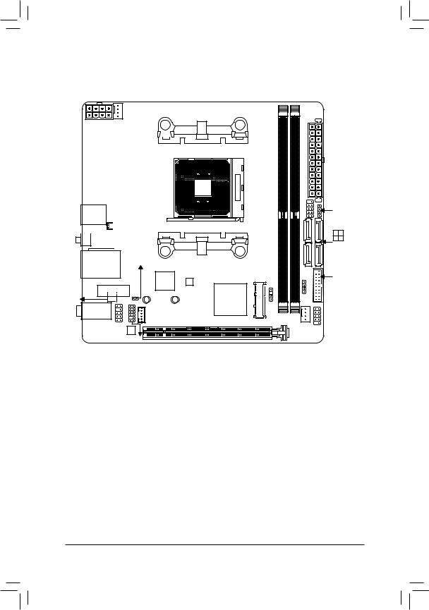
X570 I AORUS PRO WIFI Motherboard Layout
CPU_FAN
ATX_12V
|
DP |
HDMI |
|||
|
HDMI 1 |
USB30 2 |
|||
|
R |
||||
R_USB30_1

 QFLED
QFLED 
 BAT
BAT
QFLASH_PLUS

 BAT
BAT
USB31_LAN CLR_CMOS
|
iTE® |
|||
|
M2_WIFI |
Super I/O |
||
|
80 |
60 |
||
|
AUDIO |
AUDIO |
SYS_FAN2 |
|
|
F_ |
|
A1 |
B1 |
ATX |
|
DDR4_ |
DDR4_ |
|
|
Socket AM4 |
||
|
I AORUS PRO WIFI |
F PANEL |
SPEAKER |
|
X570 |
0 13 |
|
|
2 |
||
|
SATA3 |
M_BIOS
AMD X570
|
M2B SOCKET(Note) |
M2A SOCKET D LED |
Box Contents
|
55 |
X570 I AORUS PRO WIFI Motherboard |
||
|
55 |
Motherboard driver disk |
55 |
One antenna |
|
55 |
User’s Manual |
55 |
Thermal pad kit |
|
55 |
Two SATA cables |
55 |
One RGB LED strip extension cable |
*The box contents above are for reference only and the actual items shall depend on the product package you obtain. The box contents are subject to change without notice.
(Note) The chip/connector is on the back of the motherboard. — 5 —

Chapter 1 Hardware Installation
1-1 Installation Precautions
The motherboard contains numerous delicate electronic circuits and components which can become damaged as a result of electrostatic discharge (ESD). Prior to installation, carefully read the user’s manual and follow these procedures:
•• Prior to installation, make sure the chassis is suitable for the motherboard.
•• Prior to installation, do not remove or break motherboard S/N (Serial Number) sticker or warranty sticker provided by your dealer. These stickers are required for warranty validation.
•• Always remove the AC power by unplugging the power cord from the power outlet before installing or removing the motherboard or other hardware components.
•• When connecting hardware components to the internal connectors on the motherboard, make sure they are connected tightly and securely.
•• When handling the motherboard, avoid touching any metal leads or connectors.
•• It is best to wear an electrostatic discharge (ESD) wrist strap when handling electronic components such as a motherboard, CPU or memory. If you do not have an ESD wrist strap, keep your hands dry and first touch a metal object to eliminate static electricity.
•• Prior to installing the motherboard, please have it on top of an antistatic pad or within an electrostatic shielding container.
•• Before connecting or unplugging the power supply cable from the motherboard, make sure the power supply has been turned off.
•• Before turning on the power, make sure the power supply voltage has been set according to the local voltage standard.
•• Before using the product, please verify that all cables and power connectors of your hardware components are connected.
•• To prevent damage to the motherboard, do not allow screws to come in contact with the motherboard circuit or its components.
•• Make sure there are no leftover screws or metal components placed on the motherboard or within the computer casing.
•• Do not place the computer system on an uneven surface.
•• Do not place the computer system in a high-temperature or wet environment.
•• Turning on the computer power during the installation process can lead to damage to system components as well as physical harm to the user.
•• If you are uncertain about any installation steps or have a problem related to the use of the product, please consult a certified computer technician.
•• If you use an adapter, extension power cable, or power strip, ensure to consult with its installation and/or grounding instructions.
— 6 —
1-2 Product Specifications
|
CPU |
AMD Socket AM4, support for: |
|
3rd Generation AMD Ryzen™ processors/ |
|
|
2nd Generation AMD Ryzen™ processors/ |
|
|
2nd Generation AMD Ryzen™ with Radeon™ Vega Graphics processors/ |
|
|
AMD Ryzen™ with Radeon™ Vega Graphics processors |
|
|
(Go to GIGABYTE’s website for the latest CPU support list.) |
|
|
Chipset |
AMD X570 |
|
Memory |
3rd Generation AMD Ryzen™ processors: |
|
— Support for DDR4 3200/2933/2667/2400/2133 MHz memory modules |
|
|
2nd Generation AMD Ryzen™ processors/2nd Generation AMD Ryzen™ with |
|
|
Radeon™ Vega Graphics processors/AMD Ryzen™ with Radeon™ Vega Graphics |
|
|
processors: |
|
|
— Support for DDR4 2933/2667/2400/2133 MHz memory modules |
|
|
2 x DDR4 DIMM sockets supporting up to 64 GB (32 GB single DIMM capacity) |
|
|
of system memory |
|
|
Dual channel memory architecture |
|
|
Support for ECC Un-buffered DIMM 1Rx8/2Rx8 memory modules |
|
|
Support for non-ECC Un-buffered DIMM 1Rx8/2Rx8/1Rx16 memory modules |
|
|
Support for Extreme Memory Profile (XMP) memory modules |
|
|
(Go to GIGABYTE’s website for the latest supported memory speeds and memory |
|
|
modules.) |
|
Onboard |
Integrated Graphics Processor: |
|
|
Graphics (Note 1) |
— |
1 x DisplayPort, supporting a maximum resolution of 4096×2304@60 Hz |
*Support for DisplayPort 1.2 version.
—2 x HDMI port, supporting a maximum resolution of 4096×2160@60 Hz
*Support for HDMI 2.0 version, HDCP 2.2, and HDR.
Support for up to 3 displays at the same timeMaximum shared memory of 16 GB
|
Audio |
Realtek® ALC1220-VB codec |
|
|
* The back panel line out jack supports DSD audio. |
||
|
High Definition Audio |
||
|
2/4/5.1/7.1-channel |
||
|
* To configure 7.1-channel audio, you have to use an HD front panel audio module and |
||
|
enable the multi-channel audio feature through the audio driver. |
||
|
LAN |
Intel® GbE LAN chip (10/100/1000 Mbit) |
|
|
Wireless |
Wi-Fi 802.11a/b/g/n/ac/ax, supporting 2.4/5 GHz Dual-Band |
|
|
Communication |
BLUETOOTH 5.0 |
|
|
Module |
Support for 11ax 160MHz wireless standard and up to 2.4 Gbps data rate |
|
|
* Actual data rate may vary depending on environment and equipment. |
(Note 1) For 2nd Generation AMD Ryzen™ with Radeon™ Vega Graphics processors/AMD Ryzen™ with Radeon™ Vega Graphics processors only.
— 7 —
Expansion Slots Integrated in the CPU (PCIEX16):
3rd Generation AMD Ryzen™ processors:
—1 x PCI Express x16 slot, supporting PCIe 4.0 and running at x162nd Generation AMD Ryzen™ processors:
—1 x PCI Express x16 slot, supporting PCIe 3.0 and running at x16
2nd Generation AMD Ryzen™ with Radeon™ Vega Graphics processors/AMD Ryzen™ with Radeon™ Vega Graphics processors:
— 1 x PCI Express x16 slot, supporting PCIe 3.0 and running at x8 Integrated in the Chipset:
1 x M.2 Socket 1 connector for the wireless communication module (M2_WIFI)
Storage Interface Integrated in the CPU (M2A_SOCKET):
3rd Generation AMD Ryzen™ processors:
— 1 x M.2 connector (Socket 3, M key, type 2260/2280 SATA and PCIe 4.0 x4/ x2 SSD support)
2nd Generation AMD Ryzen™ processors/2nd Generation AMD Ryzen™ with Radeon™ Vega Graphics processors/AMD Ryzen™ with Radeon™ Vega Graphics processors:
— 1 x M.2 connector (Socket 3, M key, type 2260/2280 SATA and PCIe 3.0 x4/ x2 SSD support)
|
Integrated in the Chipset (M2B_SOCKET): |
||
|
— 1 x M.2 connector on the back of the motherboard (Socket 3, M key, type |
||
|
2260/2280 SATA and PCIe 4.0 (Note 2)/3.0 x4/x2 SSD support) |
||
|
— 4 x SATA 6Gb/s connectors |
||
|
— Support for RAID 0, RAID 1, and RAID 10 |
||
|
USB |
Integrated in the CPU: |
|
|
— 4 x USB 3.1 |
Gen 1 ports on the back panel |
|
|
Integrated in the Chipset: |
||
|
— 1 x USB Type-C™ port on the back panel, with USB 3.1 Gen 2 support |
||
|
— 1 x USB 3.1 |
Gen 2 Type-A ports (red) on the back panel |
|
|
— 2 x USB 3.1 |
Gen 1 ports available through the internal USB headers |
|
|
— 2 x USB 2.0/1.1 ports available through the internal USB headers |
||
|
Internal |
1 x 24-pin ATX main power connector |
|
|
Connectors |
1 x 8-pin ATX 12V power connector |
1 x CPU fan header
2 x system fan headers
1 x addressable LED strip header1 x RGB LED strip header
4 x SATA 6Gb/s connectors2 x M.2 Socket 3 connectors1 x front panel header
1 x front panel audio header1 x speaker header
1 x USB 3.1 Gen 1 header1 x USB 2.0/1.1 header
1 x Trusted Platform Module (TPM) header (2×6 pin, for the GC-TPM2.0_S module only)
1 x Clear CMOS jumper
(Note 2) For 3rd Generation AMD Ryzen™ processors only. — 8 —
|
Back Panel |
1 x DisplayPort |
||
|
Connectors |
2 x HDMI ports |
||
|
1 x USB 3.1 Gen 2 Type-A port (red) |
|||
|
4 x USB 3.1 Gen 1 ports |
|||
|
1 x USB Type-C™ port, with USB 3.1 Gen 2 support |
|||
|
1 x Q-Flash Plus button |
|||
|
1 x RJ-45 port |
|||
|
2 x SMA antenna connectors (2T2R) |
|||
|
3 x audio jacks |
|||
|
I/O Controller |
iTE® I/O Controller Chip |
||
|
Hardware |
Voltage detection |
||
|
Monitor |
Temperature detection |
||
|
Fan speed detection |
|||
|
Overheating warning |
|||
|
Fan fail warning |
|||
|
Fan speed control |
|||
|
* Whether the fan speed control function is supported will depend on the cooler you |
|||
|
install. |
|||
|
BIOS |
1 x 128 Mbit flash |
||
|
Use of licensed AMI UEFI BIOS |
|||
|
PnP 1.0a, DMI 2.7, WfM 2.0, SM BIOS 2.7, ACPI 5.0 |
|||
|
Unique Features |
Support for APP Center |
||
|
* Available applications in APP Center may vary by motherboard model. Supported |
|||
|
functionsofeachapplicationmayalsovarydependingonmotherboardspecifications. |
|||
|
— |
@BIOS |
||
|
— |
AutoGreen |
||
|
— |
Cloud Station |
||
|
— |
EasyTune |
||
|
— |
Fast Boot |
||
|
— |
Game Boost |
||
|
— |
ON/OFF Charge |
||
|
— |
RGB Fusion |
||
|
— |
Smart Backup |
||
|
— |
Smart Keyboard |
||
|
— |
Smart Survey |
||
|
— |
System Information Viewer |
||
|
— |
USB Blocker |
||
|
Support for Q-Flash Plus |
|||
|
Support for Q-Flash |
|||
|
Support for Xpress Install |
Please visit GIGABYTE’s website for support lists of CPU, memory modules, SSDs, and M.2 devices.
Please visit the SupportUtility List page on GIGABYTE’s website to download the latest version of apps.
— 9 —
|
Bundled |
Norton® Internet Security (OEM version) |
|
|
Software |
cFosSpeed |
|
|
XSplit Gamecaster + Broadcaster (12 months license) |
||
|
Operating |
Support for Windows 10 64-bit |
|
|
System |
||
|
Form Factor |
Mini-ITX Form Factor; 17.0cm x 17.0cm |
*GIGABYTE reserves the right to make any changes to the product specifications and product-related information without prior notice.
|
1-3 |
Installing the CPU |
|
|
Read the following guidelines before you begin to install the CPU: |
||
|
•• |
Make sure that the motherboard supports the CPU. |
|
|
(Go to GIGABYTE’s website for the latest CPU support list.) |
||
|
•• |
Always turn off the computer and unplug the power cord from the power outlet before installing the |
|
|
CPU to prevent hardware damage. |
||
|
•• |
Locate the pin one of the CPU. The CPU cannot be inserted if oriented incorrectly. |
|
|
•• |
Apply an even and thin layer of thermal grease on the surface of the CPU. |
|
|
•• |
Do not turn on the computer if the CPU cooler is not installed, otherwise overheating and damage |
|
|
of the CPU may occur. |
||
|
•• |
Set the CPU host frequency in accordance with the CPU specifications. It is not recommended |
|
|
that the system bus frequency be set beyond hardware specifications since it does not meet the |
||
|
standard requirements for the peripherals. If you wish to set the frequency beyond the standard |
||
|
specifications, please do so according to your hardware specifications including the CPU, graphics |
||
|
card, memory, hard drive, etc. |
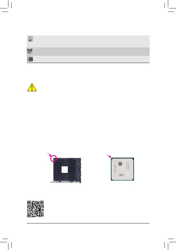
Installing the CPU
Locate the pin one (denoted by a small triangle) of the CPU socket and the CPU.
|
A Small Triangle |
A Small Triangle |
|||
|
Marking Denotes Pin |
AM4 Socket |
AM4 CPU |
||
|
Marking Denotes CPU |
||||
|
One of the Socket |
||||
|
Pin One |
||||
Please visit GIGABYTE’s website for details on hardware installation.
— 10 —
![]()
1-4 Installing the Memory
Read the following guidelines before you begin to install the memory:
•• Make sure that the motherboard supports the memory. It is recommended that memory of the same capacity, brand, speed, and chips be used.
(Go to GIGABYTE’s website for the latest supported memory speeds and memory modules.)
•• Always turn off the computer and unplug the power cord from the power outlet before installing the memory to prevent hardware damage.
•• Memory modules have a foolproof design. A memory module can be installed in only one direction. If you are unable to insert the memory, switch the direction.
Dual Channel Memory Configuration
This motherboard provides two memory sockets and supports Dual Channel Technology. After the memory is installed, the BIOS will automatically detect the specifications and capacity of the memory. Enabling Dual
Channel memory mode will double the original memory bandwidth.
The two memory sockets are divided into two channels and each channel has one memory socket as following:
Channel A: DDR4_A1Channel B: DDR4_B1
Due to CPU limitations, read the following guidelines before installing the memory in Dual Channel mode.
1.Dual Channel mode cannot be enabled if only one memory module is installed.
2.When enabling Dual Channel mode with two memory modules, it is recommended that memory of the same capacity, brand, speed, and chips be used.
1-5 Installing an Expansion Card
Read the following guidelines before you begin to install an expansion card:
•• Make sure the motherboard supports the expansion card. Carefully read the manual that came with your expansion card.
•• Always turn off the computer and unplug the power cord from the power outlet before installing an expansion card to prevent hardware damage.
1-6 Back Panel Connectors
DisplayPort (Note 1)
DisplayPort delivers high quality digital imaging and audio, supporting bi-directional audio transmission. DisplayPort can support both DPCP and HDCP 2.2 content protection mechanisms. It provides improved visuals supporting Rec. 2020 (Wide Color Gamut) and High Dynamic Range (HDR) for Blu-ray UHD playback. You can use this port to connect your DisplayPort-supported monitor. Note: The DisplayPort Technology can support a maximum resolution of 4096×2304@60 Hz but the actual resolutions supported depend on the monitor being used.
(Note 1) For 2nd Generation AMD Ryzen™ with Radeon™ Vega Graphics processors/AMD Ryzen™ with Radeon™ Vega Graphics processors only.
— 11 —
HDMI Port (Note 1)
 The HDMI port supports HDCP 2.2 (Note 1) and Dolby TrueHD and DTS HD Master


 Audio formats. It also supports up to 192 KHz/24bit 8-channel LPCM audio output. You can use this port to connect your HDMI-supported monitor. The maximum supported resolution is 4096×2160@60 Hz (Note 1), but the actual resolutions supported are dependent on the monitor being used.
After installing the DisplayPort/HDMI device, make sure to set the default sound playback device to DisplayPort/HDMI. (The item name may differ depending on your operating system.)
USB 3.1 Gen 1 Port
The USB 3.1 Gen 1 port supports the USB 3.1 Gen 1 specification and is compatible to the USB 2.0 specification. Use this port for USB devices.
USB 3.1 Gen 1 Port (White)
The USB 3.1 Gen 1 port supports the USB 3.1 Gen 1 specification and is compatible to the USB 2.0 specification. Use this port for USB devices.
Before using Q-Flash Plus (Note 2), make sure to insert the USB flash drive into this port first.
Q-Flash Plus Button (Note 2)
This button allows you to update the BIOS when the power connector is connected but the system is not powered on.
RJ-45 LAN Port
|
The Gigabit Ethernet LAN port provides Internet connection at up to 1 Gbps data rate. The following |
|||||||||||||||
|
describes the states of the LAN port LEDs. |
|||||||||||||||
|
Connection/ |
Connection/Speed LED: |
Activity LED: |
|||||||||||||
|
Speed LED |
Activity LED |
||||||||||||||
|
State |
Description |
State |
Description |
||||||||||||
|
Orange |
1 Gbps data rate |
Blinking |
Data transmission or receiving is occurring |
||||||||||||
|
Green |
100 Mbps data rate |
On |
No data transmission or receiving is occurring |
||||||||||||
|
Off |
10 Mbps data rate |
||||||||||||||
|
LAN Port |
|||||||||||||||
USB 3.1 Gen 2 Type-A Port (Red)
The USB 3.1 Gen 2 Type-A port supports the USB 3.1 Gen 2 specification and is compatible to the USB 3.1 Gen 1 and USB 2.0 specification. Use this port for USB devices.
USB Type-C™ Port
The reversible USB port supports the USB 3.1 Gen 2 specification and is compatible to the USB 3.1 Gen 1 and USB 2.0 specification. Use this port for USB devices.
SMA Antenna Connectors (2T2R)
Use this connector to connect an antenna.

 Tighten the antenna cables to the antenna connectors and then move the antenna to a place
  where the signal is good.
(Note 1) For 2nd Generation AMD Ryzen™ with Radeon™ Vega Graphics processors/AMD Ryzen™ with Radeon™ Vega Graphics processors only.
(Note 2) To enable the Q-Flash Plus function please visit the «Unique Features» webpage of GIGABYTE’s website.
— 12 —
Line In/Rear Speaker Out
The line in jack. Use this audio jack for line in devices such as an optical drive, walkman, etc.
Line Out/Front Speaker Out
The line out jack. This jack supports audio amplifying function. For better sound quality, it is recommended that you connect your headphone/speaker to this jack (actual effects may vary by the device being used). Use this audio jack for a headphone or 2-channel speaker.
Mic In/Center/Subwoofer Speaker Out
The Mic in jack.
Audio Jack Configurations:
|
Jack |
Headphone/ |
4-channel |
5.1-channel |
7.1-channel |
|
|
2-channel |
|||||
|
Line In/Rear Speaker Out |
a |
a |
a |
||
|
Line Out/Front Speaker Out |
a |
a |
a |
a |
|
|
Mic In/Center/Subwoofer Speaker Out |
a |
a |
|||
|
Front Panel Line Out/Side Speaker Out |
a |
To configure 7.1-channel audio, you have to use an HD front panel audio module and enable the multi-channel audio feature through the audio driver.
•• When removing the cable connected to a back panel connector, first remove the cable from your device and then remove it from the motherboard.
•• When removing the cable, pull it straight out from the connector. Do not rock it side to side to prevent an electrical short inside the cable connector.
Please visit GIGABYTE’s website for details on configuring the audio software.
— 13 —
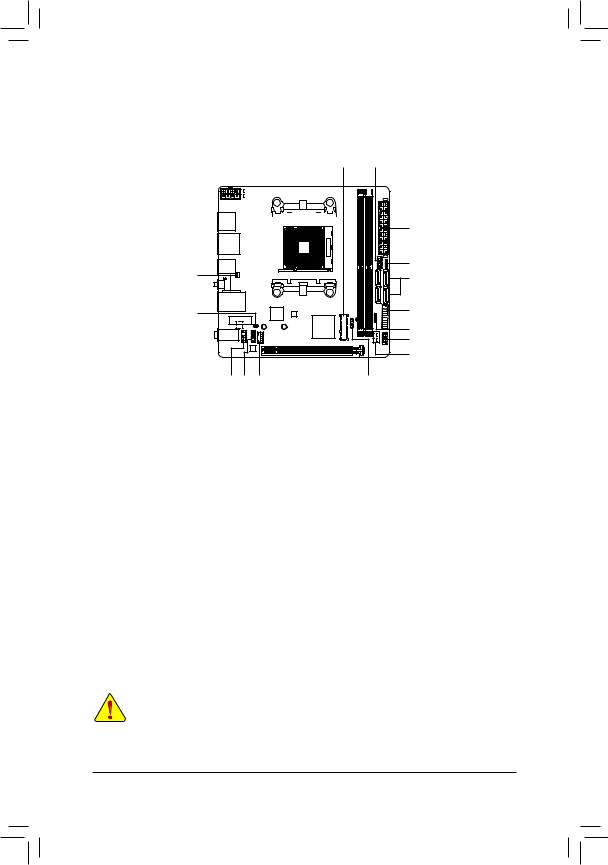
1-7 Internal Connectors
|
1 |
3 |
8 |
9 |
|||||||||||||||||||
|
2 |
|||
|
16 |
11 |
||
|
7 |
|||
|
15 |
13 |
||
|
6 |
|||
|
14 |
|||
|
4 |
|||
|
10 |
12 |
4 |
5 |
|
1) |
ATX_12V |
9) |
F_PANEL |
|
2) |
ATX |
10) |
F_AUDIO |
|
3) |
CPU_FAN |
11) |
SPEAKER |
|
4) |
SYS_FAN1/SYS_FAN2 |
12) |
TPM |
|
5) |
D_LED |
13) |
F_USB30 |
|
6) |
LED_C |
14) |
F_USB1 |
|
7) |
SATA3 0/1/2/3 |
15) |
CLR_CMOS |
|
|
M2A_SOCKET/M2B_SOCKET (Note) |
16) |
BAT |

(Note) The connector is on the back of the motherboard.
Read the following guidelines before connecting external devices:
•• First make sure your devices are compliant with the connectors you wish to connect.
•• Before installing the devices, be sure to turn off the devices and your computer. Unplug the power cord from the power outlet to prevent damage to the devices.
•• After installing the device and before turning on the computer, make sure the device cable has been securely attached to the connector on the motherboard.
— 14 —