- Manuals
- Brands
- Hach Manuals
- Controller
- sc200
- User manual
-
Contents
-
Table of Contents
-
Troubleshooting
-
Bookmarks
Quick Links
DOC023.52.80040
sc200 Controller
07/2016, Edition 8
User Manual
Related Manuals for Hach sc200
Summary of Contents for Hach sc200
-
Page 1
DOC023.52.80040 sc200 Controller 07/2016, Edition 8 User Manual… -
Page 3: Table Of Contents
Table of Contents Specifications ………………….3 General information ………………..3 Safety information ………………….4 Use of hazard information ………………4 Precautionary labels ………………… 4 Certification ………………….4 Product overview ………………….5 Sensors and sensor modules …………….6 Relays outputs and signals ………………. 6 Device scans ………………….
-
Page 4
Table of Contents Display setup ………………….39 Update the date and time ………………40 Set the datalog mode and interval …………….40 Set up a calculation ………………..40 Set up the discrete inputs ………………41 Update the display language ………………42 Using the secure digital memory (SD) card …………… -
Page 5: Specifications
Specifications Specifications are subject to change without notice. Specification Details Component description Microprocessor-controlled and menu-driven controller that operates the sensor and displays measured values. Operating temperature -20 to 60 ºC (-4 to 140 ºF); 95% relative humidity, non-condensing with sensor load <7 W;…
-
Page 6: Safety Information
make changes in this manual and the products it describes at any time, without notice or obligation. Revised editions are found on the manufacturer’s website. Safety information N O T I C E The manufacturer is not responsible for any damages due to misapplication or misuse of this product including, without limitation, direct, incidental and consequential damages, and disclaims such damages to the full extent permitted under applicable law.
-
Page 7: Product Overview
Supporting test records reside with the manufacturer. This Class A digital apparatus meets all requirements of the Canadian Interference-Causing Equipment Regulations. Cet appareil numérique de classe A répond à toutes les exigences de la réglementation canadienne sur les équipements provoquant des interférences. FCC Part 15, Class «A»…
-
Page 8: Sensors And Sensor Modules
Figure 1 System components 1 Controller 4 Network module (optional) 2 Strain relief assembly (optional depending on 5 High-voltage barrier controller version) 3 Digital connection fitting (optional depending on 6 Sensor modules (optional) controller version) Sensors and sensor modules The controller accepts up to a maximum of two sensor modules or two digital sensors (depending on the controller configuration), along with one communication module.
-
Page 9: Installation
Installation Mounting components and dimensions C A U T I O N Personal injury hazard. Only qualified personnel should conduct the tasks described in this section of the manual. The controller can be installed on a surface, panel or pipe (horizontal or vertical). For mounting options and instructions, refer to Figure Figure 3…
-
Page 10: Controller Mounting
Controller mounting Figure 3 Surface mounting dimensions 8 English…
-
Page 11
Figure 4 Panel mounting dimensions Note: If using the bracket (optional) for panel mounting, push the controller through the hole in the panel and then slide the bracket over the controller on the back side of the panel. Use the four 15 mm pan head screws (supplied) to attach the bracket to the controller and secure the controller to the panel. -
Page 12
Figure 5 Pipe mounting (vertical pipe) 10 English… -
Page 13: High-Voltage Barrier
Figure 6 Top and bottom views High-voltage barrier High-voltage wiring for the controller is located behind the high-voltage barrier in the controller enclosure. The barrier must remain in place except when installing modules or when a qualified installation technician is wiring for power, alarms, outputs or relays. Do not remove the barrier while power is applied to the controller.
-
Page 14: Wiring Overview
• Avoid excessive movement. Transport static-sensitive components in anti-static containers or packages. • Wear a wrist strap connected by a wire to earth ground. • Work in a static-safe area with anti-static floor pads and work bench pads. Wiring overview Figure 7 shows an overview of the wiring connections inside the controller with the high voltage barrier removed.
-
Page 15
W A R N I N G Potential Electrocution Hazard. If this equipment is used outdoors or in potentially wet locations, a Ground Fault Interrupt device must be used for connecting the equipment to its mains power source. D A N G E R Electrocution Hazard. -
Page 16
Table 2 DC power wiring information (DC powered models only) Terminal Description Color—North America Color—EU +24 VDC 24 VDC return Black Black — Protective Earth (PE) Ground lug Green Green with yellow stripe 14 English… -
Page 17: Alarms And Relays
Alarms and relays The controller is equipped with four unpowered, single pole relays rated 100-250 VAC, 50/60 Hz, 5 amp resistive maximum. Contacts are rated 250 VAC, 5 amp resistive maximum for the AC powered controller and 24 VDC, 5A resistive maximum for the DC powered controller. The relays are not rated for inductive loads.
-
Page 18
The wiring compartment is not designed for voltage connections in excess of 250 VAC. 24 VDC powered controllers W A R N I N G Potential electrocution hazard. AC mains powered controllers (115 V–230 V) are designed for relay connections to AC mains circuits (i.e., voltages greater than 16 V-RMS, 22.6 V-PEAK or 35 VDC). W A R N I N G Potential electrocution hazard. -
Page 19: Analog Output Connections
Analog output connections W A R N I N G Potential Electrocution Hazard. Always disconnect power to the instrument when making electrical connections. W A R N I N G Potential electrocution hazard. In order to maintain the NEMA/IP environmental ratings of the enclosure, use only conduit fittings and cable glands rated for at least NEMA 4X/IP66 to route cables in to the instrument.
-
Page 20: Discrete Input Wiring Connections
4. Make connections with twisted-pair shielded wire and connect the shield at the controlled component end or at the control loop end. • Do not connect the shield at both ends of the cable. • Use of non-shielded cable may result in radio frequency emission or susceptibility levels higher than allowed.
-
Page 21
Figure 9 Discrete input wiring connections Table 4 Input connections Discrete inputs Connector position — Switch input Connector position — Voltage input Input 1+ Input 1- Input 2+ Input 2- Input 3+ Input 3- English 19… -
Page 22: Connect A Digital Sc Sensor
Figure 10 Jumper settings 1 Input 1 configuration jumpers 4 Jumpers positioned to the left for switch inputs 2 Input 2 configuration jumpers 5 Jumpers positioned to the right for voltage inputs 3 Input 3 configuration jumpers 1. Open the controller cover. 2.
-
Page 23: Connect The Optional Digital Communication Output
For information about Modbus registers, go to http://www.de.hach.com http://www.hach.com search Modbus registers or go to any sc200 product page. Install a Secure Digital (SD) memory card For instructions on how to install an SD card in the controller, refer to Figure 12.
-
Page 24: User Interface And Navigation
User interface and navigation User interface The keypad has four menu keys and four directional keys as shown in Figure Figure 13 Keypad and front panel overview 1 Instrument display 5 BACK key. Moves back one level in the menu structure.
-
Page 25: Additional Display Formats
Figure 14 Example of Main Measurement screen 1 Home screen icon 7 Warning status bar 2 Sensor name 8 Date 3 SD Memory card icon 9 Analog output values 4 Relay status indicator 10 Time 5 Measurement value 11 Progress bar 6 Measurement unit 12 Measurement parameter Table 5 Icon descriptions…
-
Page 26: System Startup
Troubleshooting on page 46. Controller configuration information General information about configuration options is listed in the table. 1. To navigate to the menu options, from the Settings Menu, select sc200 Setup. Option Description Security setup Sets the passcode preferences (refer to…
-
Page 27: Advanced Operation
4. Select Disabled or Enabled and push the ENTER key. The passcode is enabled. 5. Push the BACK key to return to the sc200 Setup Menu, or push the MENU key to return to the Settings Menu. Edit the passcode The passcode is factory set to SC200.
-
Page 28: Protect Features
1. Make sure the passcode is enabled. Refer to Enable or disable the passcode on page 25 for information on how to enable the passcode. 2. From the Settings menu, select Security Setup and push ENTER. 3. Use the arrow keys to enter the current valid passcode and push ENTER. The Edit Passcode option appears in the Security Setup menu.
-
Page 29: Configure A 4-20 Ma Output Module
BACK key to cancel. For additional information, refer to the sc200 4–20 Analog Input Module User Manual. Configure a 4-20 mA output module The Network Setup option appears in the Settings Menu only if an analog output module or other network module such as Modbus or Profibus is installed in the controller.
-
Page 30
4. Choose Select Source and select a source from the list. Typically the source is one of the sensors attached to the system. If an analog input card is installed, the analog input may be used as a source. 5. From the Output Setup menu, choose Select Parameter and choose an option from the list. Parameters will vary depending on the type of sensors installed. -
Page 31: Logarithmic Output Mode
• Logarithmic Option Description Set 50% value Sets the value corresponding to 50% of the process variable range. Set high value Sets the upper value of the process variable range. • Bilinear Option Description Set low value Sets the low endpoint value of the process variable range. Set high value Sets the high endpoint value of the process variable range.
-
Page 32: Configure Relays
(unless the Fail Safe is set to Yes), or when power is removed from the controller. To select a menu option, highlight the option and push ENTER. 1. From the sc200 Setup menu, select Relay Setup. 2. Select a relay from the list.
-
Page 33
Option Description Frequency control Relay switches with a frequency depending on a process value Warning Relay indicates warning and error conditions in probes 6. From the Relay Setup menu, select Set Transfer and choose Active or Inactive. 7. From the Relay Setup menu, select Fail Safe and choose Yes or No. 8. -
Page 34
Option Description Low deadband Sets the range where the relay remains on after the measured value increases above the low alarm value. For example, if the low alarm is set for 1.0 and the low deadband is set for 0.5, the relay remains on between 1.0 and 1.5. Default is 5% of the range. High deadband Sets the range where the relay remains on after the measured value decreases below the high alarm value. -
Page 35
Option Description Overfeed timer Sets a time period for de-activating an active relay if the process setpoint cannot be reached. Once an overfeed alarm is present, it must be manually reset. Off delay Sets a delay time for the relay to turn off (default: 0 seconds). On delay Sets a delay time for the relay to turn on (default: 0 seconds). -
Page 36
Figure 20 Feeder control function (Phase low, Overfeed timer) 1 Deadband 5 ON delay 2 Setpoint 6 OFF delay 3 Overfeed timer 7 Source (y-axis) 4 Time (x-axis) • Event Control Function (refer to Figure Figure 22 Figure Option Description Set setpoint Sets the value where the relay will turn on. -
Page 37
Figure 21 Event control function (no delay) 1 Source (y-axis) 5 Low alarm 2 High alarm 6 Time (x-axis) 3 Deadband 7 OnMax-time 4 Setpoint 8 OffMax-time English 35… -
Page 38
Figure 22 Event control function (OnMin timer, OffMin timer) 1 High alarm 5 Time (x-axis) 2 Deadband 6 OffMin timer 3 Setpoint 7 OnMin timer 4 Low alarm 8 Source (y-axis) Figure 23 Event control function (ON/OFF delay) 1 High alarm 4 OFF delay 2 Low alarm 5 Time (x-axis) -
Page 39
• Pulse Width Modulation Control Function (refer to Figure Option Description Set mode Auto—the relay output works as a PID controller. Manual—the signal is controlled by the user through manual adjustment of the % change value. This option is shown as Manual Output after the manual set mode is selected. Phase Reverses the leading sign of the control deviation for the PID controller (default: Reverse). -
Page 40
• Frequency Control Function (refer to Figure Option Description Set mode Auto—The relay works as a PID controller. Manual—the signal is controlled by the user through manual adjustment of the % change value. This option is shown as Manual Output after the manual set mode is selected. Phase Reverses the leading sign of the control deviation for the PID controller (default: Reverse). -
Page 41: Display Setup
Warning Sets the level for warning activation. Refer to the sensor manual for the numbers for individual warning messages. Display setup Configures the controller display. 1. From the Settings menu, select sc200 Setup and push ENTER. 2. Select Display Setup and push ENTER. Option Description Adjust Order View and modify the measurement display order.
-
Page 42: Update The Date And Time
Update the date and time 1. From the Settings menu, select sc200 Setup and push ENTER. 2. Select Set Date/Time and push ENTER. 3. Select Date Format from the Set Date/Time screen and push ENTER. 4. Select a format and push ENTER.
-
Page 43: Set Up The Discrete Inputs
Use these inputs to switch closure inputs or logic level voltage inputs. 1. Press the MENU key. 2. Select sc200 Setup and push ENTER. 3. Select Discrete Input Setup and push ENTER. 4. Select the desired channel (Input 1, Input 2 or Input 3) and push ENTER.
-
Page 44: Update The Display Language
Update the display language The display language can be changed through the Setup menu. 1. From the Settings Menu, select sc200 Setup and push ENTER. 2. Select Language and push ENTER. The list of language options appears. English is the default language for the controller.
-
Page 45: Saving Data And Event Logs With Sd Cards
1. Attach the card reader device to the PC (if necessary) and install the SD card that contains the files in the reader device. 2. In the SD card directory, open the HACH folder. 3. Select the Logs folder. 4. Select a device folder.
-
Page 46: Firmware Updates With Sd Cards
A PC and a USB card reader or other device capable of reading an SD card are necessary. 1. Find the zip file at http://www.hach-lange.com http://www.hach.com and copy it to the PC. 2. Extract file(s) from the zip folder and save them to the SD card.
-
Page 47: Transfer Settings To Another Device
The DataCom application must be installed on a PC to read the files. Refer to the DataCom manual for more information on how to use the application. The DataCom manual, software updates and other downloadable resources are available at http://www.de.hach.com http://www.hach.com on any sc200 product page. English 45…
-
Page 48: Maintenance
Maintenance D A N G E R Multiple hazards. Only qualified personnel must conduct the tasks described in this section of the document. Cleaning the controller D A N G E R Always remove power from the controller before performing maintenance activities. Note: Never use flammable or corrosive solvents to clean any part of the controller.
-
Page 49
Problem Resolution Make sure relay connections are secure. If using an external power source, make sure the relay wiring is correct. Make sure the relay configuration is correct. Test the relay activation through the Test/Maintenance menu. No relay activation The relay should energize and de-energize as selected. Make sure the controller is not in calibration mode and that the relay is not being held. -
Page 50: Test And Maintenance Menu
Problem Resolution Make sure the AC power connections are properly terminated in the controller. Controller will not power up, or powers up Make sure the power strip, line power, wall plug are all properly intermittently plugged in. Contact Technical Support Make sure the module is properly installed.
-
Page 51: Warning And Error Conditions
Reset default config Resets the controller configuration settings to the default values (language, date and time, relay function and data output function). Restart sc200 Performs a controller restart Simulation (only After the sim value is entered, the controller outputs this value as if it was the displays if sensors or value sent from the sensor.
-
Page 52: Device Scan Information
Power cord kit, with strain relief, 230 VAC, European-style plug 9203000 Screw driver 6134300 SD card reader 9218200 SD card cover kit for sc200 controller 9200900 Screws for controller installation kit 9177800 Cord grip kit (1) 9178000 Sealing washer for cord grip assembly…
-
Page 53
Description Item number Flow module 9012700 4-20 mA input module 9012800 pH and DO module 9012900 4-20 mA output module 9334600 HART network module kit 9328100 Modbus network module 9013200 Profibus network module 9173900 Profibus M12 connector kit 9178500 Profibus M12 socket (hard wire to quick connector adapter) 9178200 Profibus M12 T-splitter 9178400… -
Page 54
52 English… -
Page 56
Tel. +49 (0) 2 11 52 88-320 SWITZERLAND Fax (970) 669-2932 Fax +49 (0) 2 11 52 88-210 Tel. +41 22 594 6400 orders@hach.com info-de@hach.com Fax +41 22 594 6499 www.hach.com www.de.hach.com © Hach Company/Hach Lange GmbH, 2011-2014, 2016. All rights reserved. Printed in Germany.
DOC023.98.80040
sc200 Controller
08/2013, Edition 6
Basic User Manual
Basis-Bedienungsanleitung
Manuale dell’utente di base
Manuel d’utilisation de base
Manual básico del usuario
Manual de operações básicas
Základní uživatelská příručka
Grundlæggende brugervejledning
Basisgebruikershandleiding
Podstawowa instrukcja obsługi
Grundläggande bruksanvisning
Peruskäyttöohje
Основно ръководство за потребителя
Alapvető felhasználói útmutató
Manual de bază al utilizatorului
Bendroji naudotojo instrukcija
Начальное руководство пользователя
Temel Kullanıcı Kılavuzu
Základný návod na použitie
Osnovni uporabniški priročnik
Osnovni korisnički priručnik
Βασικό εγχειρίδιο λειτουργίας
Kokkuvõtlik kasutusjuhend
Osnovno korisničko uputstvo
Универсальный контроллер HACH SC200 с ультразвуковым датчиком расхода

Универсальный контроллер SC200 с ультразвуковым датчиком предназначен для обеспечения высокоточных измерений расхода и глубины для приложений мониторинга расхода в открытом канале.
От легко читаемого дисплея до надежного управления данными с передачей данных на SD-карту, проточная система представляет собой экономичный выбор для мониторинга расхода.
Проточная система может использоваться для различных применений, в том числе в соответствии с требованиями разрешений NPDES и для мониторинга ливневых вод, входного стока, конечных стоков и активного ила. Он заменяет аналоговый контроллер Hach GLI53 с расширенными функциями для упрощения использования оператором.
Платформа контроллера SC200 может быть сконфигурирована для работы либо с 2 входами цифровых датчиков, либо с 1 или 2 входами аналоговых датчиков, либо с комбинацией входов цифровых и аналоговых датчиков. Клиенты могут выбирать варианты связи из множества предложений, начиная от MODBUS RTU и заканчивая Profibus DPV1.
Максимальная универсальность
- Стандартизированный контроллер устраняет необходимость в различных специализированных контроллерах.
- Многоканальный контроллер управляет 1 или 2 датчиками, что снижает затраты на хранение запасов и обеспечивает недорогой вариант добавления второго датчика в более позднее время.
- Настоящий контроллер с двумя датчиками обеспечивает выходы 4–20 мА для передачи первичных и вторичных значений измерений
- Контроллер может быть установлен на панели, поверхности или на столбе (оборудование входит в комплект)
Монитор
- Большой дисплей с прокручиваемым меню для легкой настройки
- Трансрефлективный дисплей остается читаемым даже при солнечном свете
Управление данными
- SD-карта упрощает загрузку и передачу данных
- Обновление прошивки через SD-карту или специальный кабель RS232
Ультразвуковой датчик потока
- Выберите первичную гидрометрическую структуру из библиотеки лотков и водосливов для настройки датчика расхода или введите кривую расхода для нестандартной конструкции.
- Бесконтактный датчик расхода не требует регулярного обслуживания
- Технология импульсного эха
Входы датчиков
- Модули аналоговых датчиков могут быть добавлены в полевых условиях.
- Порты цифровых датчиков устанавливаются на заводе
- Контроллер будет сканировать и обнаруживать новые добавленные датчики
- Работает с цифровыми датчиками GLI и Hach
Аналоговые входы
- Включает мониторинг анализатора, отличного от sc
- Принимает сигналы мА от других анализаторов для локального отображения
- Объединяет аналоговые сигналы мА в цифровой выход 4-20 мА Выходы
- Всего шесть (6) выходов 4–20 мА (2 стандартных/4 опционально) обеспечивают выходы до 3 мА на каждый вход датчика
Цифровая связь
- MODBUS 232/485 и Profibus DP V1.0
Простота использования и уверенность в результатах
- Новый дисплей и управляемые процедуры калибровки уменьшают количество ошибок оператора
- Защита паролем для предотвращения тampнежелательные и нежелательные программные изменения
- Система визуального предупреждения обеспечивает критические предупреждения
Характеристики
Общие характеристики SC200
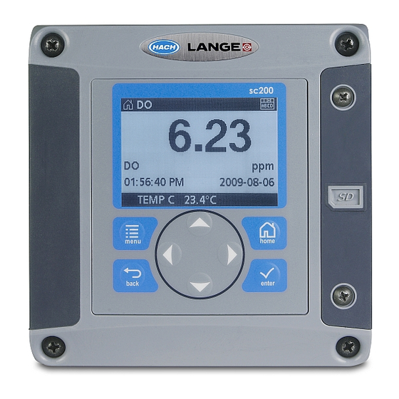
- Дисплей Графическая точечная матрица LCD со светодиодной подсветкой. трансрефлексивный
- Размер дисплея 48 x 68 мм (1.89 x 2.67 дюйма)
- Разрешение дисплея 240 х 160 пикселей
- Высота х Ширина x глубина 144 x 144 x 181 мм (5.7 x 5.7 x 7.1 дюйма)
- Вес 1.70 кг (3.75 фунтов)
- Требования к питанию 100–240 В переменного тока ±10 %, 50/60 Гц; 24 В постоянного тока -15% + 20%
- Рабочая Температура От -20 до 60 °C (от -4 до 140 °F), от 0 до 95 % относительной влажности без конденсации
- Температура хранения —от 20 до 70 °C (от -4 до 158 °F), от 0 до 95 % относительной влажности без конденсации
Аналоговый выходной сигнал
- Две Изолированные токовые выходы от 0/4 до 20 мА, макс. 500 Ом
- Основной режим работы или вторичное измерение или расчетное значение (только для двухканального режима) Режим работы Линейный, Логарифмический, Билинейный, ПИД
- Опционально 4 дополнительных Изолированные токовые выходы 4/20 мА, макс. 500 Ом при 18–24 В пост. тока (источник питания предоставляется заказчиком) макс. 500 Ом при 18–24 В пост.
- Уровни безопасности Два уровня защиты паролем
- Материалы корпуса Поликарбонат, Алюминий (с порошковым покрытием), Нержавеющая сталь
- Монтажные конфигурации Крепление к стене, столбу и панели
- Рейтинг шкафа NEMA 4X / IP 66
- Отверстия для проводов Трубка 1/2″ NPT
- Реле
Четыре электромеханических контакта SPDT (форма C), 1200 Вт, 5 А, 250 В переменного тока
Рабочий режим Первичное или вторичное измерение, расчетное значение (только для двухканального режима) или таймер - Цифровая связь MODBUS RS232/RS485, Profibus DPV1 опционально
- Резервное копирование памяти Флэш-память
- Электрические сертификаты
ЭМС: Соответствие стандартам CE для кондуктивных и излучаемых излучений CISPR 11 (ограничения класса A), устойчивость к электромагнитным помехам EN 61326-1 (промышленные ограничения)
Безопасность: UL/CSA 61010-1 общего назначения со знаком безопасности cETLus - Регистрация данных
Secure Digital Card (максимальная рекомендуемая емкость 8 ГБ) или специальный кабельный разъем RS232 для регистрации данных и выполнения обновлений программного обеспечения.
Ультразвуковой датчик потока
Скорость потока
- Расход 0–9999, 0–999.9, 0–99.99 с возможностью выбора единиц измерения расхода
- Громкости 0-9,999,999 XNUMX XNUMX с выбираемыми единицами объема
- Диапазон/разрешение измерения глубины единицы измеренияот 0.25 м (10 дюймов) до 6 м (20 футов) ±1 мм (0.04 дюйма)
- Температура воздуха от -40 до 90°C (от -40 до 194°F)±0.1°C (0.18°F)
- Входной фильтр 999 с
- Сумматоры Программный сумматор с 8-разрядным ЖК-дисплеем с возможностью сброса
- Суммарный поток. Гал., фут3, акр-фут., литр, м3, дюйм3Сумматор может быть установлен в автоматический или ручной режим. (Опция меню для сброса доступна только в ручном режиме.)
- точность ± 0.5% диапазона
- Повторяемость ± 0.1% диапазона
- Время отклика Менее 180 секунд до 90% значения при ступенчатом изменении
- Кабель датчика 10 м (33 фута), 20 м (66 футов),
- (интегрально) Длина 50 м (164 фута) или 100 м (328 футов)
- Методы калибровки Глубина калибровки 1 балл; Калибровка Глубина 2 балла
- Рабочая частота 75kHz
- Строительство Корпус из полибутилентерефталата (PBT) NEMA 6P (IP68) со встроенным датчиком температуры
- Вес ~ 0.5 кг (1.1 фунта)
Выберите один из следующих типов датчиков:
- V-образная плотина
- Прямоугольная плотина
- Прямоугольный желоб
- Круглый канал для ботов
- Чиполлетти Вейр
- Нейрпик Флюм
- Паршалл Флюм
- П. Боулус Флюм
- Хафаги Флюм
- L Lagco Flume
- Канал типа H
- Трапециевидный лоток
- User Defined
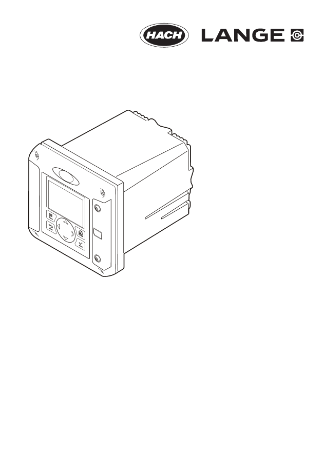
Размеры
Блок контроллера SC200 можно установить на поверхность, панель или трубу (горизонтально или вертикально). Для подключения блока контроллера к любому цифровому датчику Hach не требуются инструменты. ПРИМЕЧАНИЕ: Размеры указаны в дюймах [миллиметрах].

Минимальные промежутки для группового монтажа
Информация для заказа
| Интеллектуальная система нумерации деталей контроллера и модуля SC200 | 0 | 0 | 3 | 0 | 2 |
| LXV404.99. | X | X | X | X | X |
| Питания | |||||
| Нет шнура питания | 0 | ||||
| Нет шнура питания | 1 | ||||
| С кабелем питания ЕС, установленным с зажимом для шнура | 2 | ||||
| С кабелем питания для Великобритании, установленным с зажимом для шнура | 3 | ||||
| С кабелем питания США, установленным с зажимом для шнура | 5 | ||||
| Блок питания 24VCD без шнура или зажимов для шнура | 7 | ||||
| Коммуникация Результат | |||||
| Стандарт (два выхода 4-20 мА) | 0 | ||||
| МОДБУС 232 и 485 | 1 | ||||
| Профибус ДП | 3 | ||||
| HART + четыре аналоговых выхода 4–20 мА | 5 | ||||
| Четыре дополнительных аналоговых выхода 4-20 мА | 9 | ||||
| Вход датчика 1 | |||||
| рН и DO | 1 | ||||
| Проводимость | 2 | ||||
| Поток | 3 | ||||
| вход мА | 4 | ||||
| Цифровое | 5 | ||||
| Вход датчика 2 | |||||
| Ничто | 0 | ||||
| рН и DO | 1 | ||||
| Проводимость | 2 | ||||
| Поток | 3 | ||||
| вход мА | 4 | ||||
| Цифровое | 5 | ||||
| Бренд | |||||
| Хач | 2 |
Ультразвуковые датчики потока
- У53С010 Ультразвуковой датчик с 10-футовым кабелем
- У53С030 Ультразвуковой датчик с 30-футовым кабелем
- У53С100 Ультразвуковой датчик с 100-футовым кабелем
Кабели питания
- Шнур питания Sc200 с компенсатором натяжения, 125 В переменного тока
- 9202900 шнур питания Sc200 с компенсатором натяжения,
- 9203000 230 В перем. тока, европейская вилка
Комплектация
- 9220600 SC200 Weather and Sun Shield с экраном для защиты от УФ-излучения
- 8809200 SC200 УФ-защитный экран
- 1000G3088-001 Защитный кожух от непогоды
- 9218200 Устройство чтения SD-карт (USB) для подключения к ПК
- 9218100 4 ГБ SD-карта
- 9012700 Модуль потока
- 9013100 Модуль для 4 дополнительных аналоговых выходов мА (пассивный)
- 9013200 Модуль Modbus
- ЯБ104 Комплект Profibus DP
- LZX887 Кабель передачи данных
- 3004А0017-001 Монтажный комплект датчика расхода
Штаб-квартира Hach World: Лавленд, Колорадо, США
США: 800-368-2723 тел. 970-669-5150 факс hachflowsales@hach.com
За пределами США: 970-622-7120 тел.
hachflow.com
Напечатано в США ©Hach 2022. Все права защищены.
В интересах улучшения и обновления своего оборудования Hach оставляет за собой право изменять технические характеристики оборудования в любое время.
Документы / Ресурсы
Рекомендации

Flow — Онлайн-инструменты | Хач

измерения для устройства в положении 1. Если контроллер не смог обнаружить
подключенные устройства, обратитесь к разделу
Поиск и устранение проблем
на стр. 451.
Сведения о настройке контроллера
В таблице приведены общие сведения возможных настройках.
1. Для перемещения по опциям меню выберите в меню настроек пункт «Настройка sc200».
Опция
Наименование
Настройки безопасности
Задает настройки парольной защиты.
Настройка выхода
Настраивает аналоговые выходы контроллера
Настройка реле
Настраивает реле контроллера
Настройка дисплея
Настраивает дисплей контроллера
Установка даты/времени
Устанавливает дату и время в контроллере
Настройки регистрации
данных
Выполняет настройки регистрации данных. Доступно только в том
случае, если был настроен режим «Расчет».
Управление данными
Чтобы посмотреть данные или журнал событий, выберите устройство
из списка установленных компонентов
Режим удержания ошибки
Удержание выходов—На выходах удерживается последнее
значение, известное к моменту потери контроллером связи с датчиком.
Передача выходов—Переключение в режим передачи, когда
контроллер теряет связь с датчиком. Выход переводится на
предустановленное значение.
Calculation (Вычисление)
Настраивает математическую функцию контроллера
Информация об sc200
ВЕРСИЯ ПО:—Выводится текущая версия программного обеспечения
контроллера
ВЕРСИЯ ЗАГРУЗЧИКА:—Выводится текущая версия загрузчика.
Загрузчик представляет собой файл, загружающий основную
операционную систему контроллера
С/Н:—Выводится серийный номер контроллера
Версия:—Отображает текущую версию оборудования контроллера
Discrete Input Setup
(Настройка дискретного
ввода данных)
Настраивает три отдельных входных канала
Язык
Задает язык, используемый контроллером
2. Выберите опцию и нажмите ВВОД для активации элемента меню.
Обслуживание
О С Т О Р О Ж Н О
Различные опасности. Работы, описываемые в данном разделе, должны выполняться только
квалифицированным персоналом.
450 Русский
Технические характеристики
В технические характеристики могут быть внесены изменения без
предварительного уведомления.
Таблица 1 Технические характеристики ультразвукового
модуля расхода
Характеристика
Скорость потока
Полный расход
Погрешность
Чувствительность
Воспроизводимость
Время отклика
Входной фильтр
Таблица 2 Технические характеристики модуля расхода с
крыльчатым колесом
Характеристика
Диапазон частот
Скорость потока
Абсолютная погрешность
Чувствительность
Воспроизводимость
Входной фильтр
84 Русский
Данные
Функциональные возможности
конструкции затворного типа
0-999 999 999 с выбираемым
расходом и узлами умножителей
± 0,5% диапазона
± 0,1% диапазона
± 0,1% диапазона
Менее 180 секунд до 90% значения
при ступенчатом изменении
999 секунд
Данные
0-5000 Гц
Функциональные возможности
размеров монтажной арматуры
± 0,1% диапазона
± 0,1% диапазона
± 0,05% диапазона
999 секунд
Таблица 2 Технические характеристики модуля расхода с
крыльчатым колесом (продолжение)
Характеристика
Температурный дрейф
Время отклика
Общая информация
Производитель ни при каких обстоятельствах не несет
ответственности за прямой, непрямой, умышленный, неумышленный
или косвенный ущерб в результате любых недочетов или ошибок,
содержащихся в данном руководстве. Производитель оставляет за
собой право вносить изменения в руководство или описанную в нем
продукцию без извещений и обязательств. Все обновления можно
найти на веб-сайте производителя.
Указания по безопасности
Внимательно прочтите все руководство пользователя, прежде чем
распаковывать, устанавливать или вводить в эксплуатацию
оборудование. Соблюдайте все указания и предупреждения
относительно безопасности. Их несоблюдение может привести к
серьезной травме обслуживающего персонала или выходу из строя
оборудования.
Чтобы гарантировать, что обеспечиваемая оборудованием защита
не нарушена, не используйте или не устанавливайте данное
оборудование никаким иным способом, кроме указанного в данном
руководстве.
Информация о потенциальных опасностях
О П А С Н О С Т Ь
Указывает на потенциальные или непосредственно опасные ситуации,
которые при нарушении могут привести к серьезным травмам или смерти.
Данные
Нуль и диапазон: ± 0,02% от
диапазона на °C
от 1-60 секунд до 90% значения при
ступенчатом изменении