hp-detect-load-my-device-portlet
![]()
Действия
- ${title}
Загрузка…
hp-product-information-portlet
![]()
Действия
- ${title}
Загрузка…
У вас уже есть учетная запись HP? Выберите продукты, которыми вы владеете.
Войти
/
Зарегистрироваться
Серия настольных моноблоков HP 24-g000 All-in-One
Выбрать другие серии продуктов
![]()
Добавить этот продукт в личную панель


Этот продукт был добавлен в личную панель
hp-product-builder-portlet
![]()
Действия
- ${title}
Загрузка…
hp-pdp-secondary-navigation-portlet
![]()
Действия
- ${title}
Загрузка…
hp-promotion-tiles-portlet
![]()
Действия
- ${title}
Загрузка…
hp-country-locator-portlet
![]()
Действия
- ${title}
Загрузка…
Страна/регион:

Казахстан
hp-product-warranty-check
![]()
Действия
- ${title}
Загрузка…
перейти к содержанию
Серия принтеров HP All-in-One
Руководство пользователя
Чернила HP DeskJet Advantagэлектронной 2770
Серия принтеров All-in-One
Все самое необходимое — рассчитывайте на простую настройку с помощью приложения HP Smart и получите беспроблемную беспроводную связь.
Все основы теперь с простыми в использовании функциями. Печатайте, сканируйте и копируйте повседневные документы и получайте беспроблемную беспроводную связь. Простая настройка с помощью приложения HP Smart означает, что вы готовы к работе с любым устройством.


Простая установка. Простая печать.
- Начните работу быстро благодаря простой настройке, которая проведет вас через каждый шаг с помощью приложения HP Smart2.
- С легкостью справляйтесь с задачами и получайте много всего на одном устройстве — печатайте, сканируйте и копируйте.
- С легкостью печатайте повседневные документы со своего смартфона с помощью приложения HP Smart2.
- С приложением HP Smart вы получите высококачественное сканирование и отправку, а также легкое копирование со своего смартфона.

Беспокойство беспроводной
- Увеличьте радиус действия, а также более быстрые и надежные соединения с помощью двухдиапазонного Wi-Fi® с функцией автоматического сброса.
- Подключайтесь с помощью Bluetooth® и начинайте быстро печатать со своего смартфона или планшета — простая настройка.
- Встроенные возможности беспроводной связи позволяют легко получать доступ, печатать и совместно использовать ресурсы в сети.
- Подключитесь и начните печать. Легко подключите принтер к компьютеру с помощью встроенного USB-порта

Качество, на которое можно положиться
- Оригинальные струйные картриджи HP обеспечивают четкий текст и яркую графику для всех ваших повседневных документов и фотографий.
Технические характеристики HP DeskJet Ink AdvantagМФУ серии e 2770 All-in-One
Технические характеристики

Информация для заказа

© 2020 HP Development Company, LP Информация, содержащаяся в данном документе, может быть изменена без предварительного уведомления. Единственные гарантии для продуктов и услуг HP изложены в заявлениях о прямой гарантии, прилагаемых к таким продуктам и услугам. Ничто в данном документе не должно толковаться как дополнительная гарантия. В той степени, в которой это разрешено законом, HP не несет ответственности за технические или редакторские ошибки или упущения, содержащиеся в данном документе.
4AA7-7398EEAP, июль 2020 г.
Документы / Ресурсы
Рекомендации
HP DeskJet 2320 All-in-One недорогой и довольно популярный МФУ в белом компактном корпусе, который представляет собой очень удобное приспособление для печати и способен решать многочисленные задачи. Основными направлениями работы устройства являются копирование документов, печать, а также их сканирование, при котором осуществляется перевод документов в электронный вид. В качестве носителей аппарат использует бумагу для брошюр, обычную бумагу, а также фотобумагу, поэтому МФУ будет идеальным аппаратом для решения различных задач.
При распечатке в черно-белом варианте максимальная скорость составляет 7.5 страниц, а в цвете — 5.5 страниц в минуту. Производитель также оснастил струйный МФУ HP DeskJet 2320 возможностью распечатки конвертов и фотографий. Сканирующее устройство представлено тут планшетным типом. Максимальный формат сканирования здесь А4. Скорость копирования листов формата А4 достигает 6 страниц за одну минуту. Максимальное количество копий за один цикл равно 9 экземплярам.
Устройство принтера
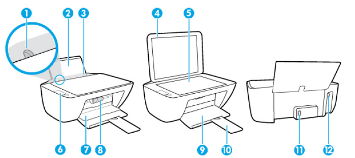
- Направляющая ширины бумаги
- Входной лоток
- Крышка входного лотка
- Крышка сканера
- Стекло сканера
- Панель управления
- Крышка доступа к картриджам
- Картриджи
- Выходной лоток
- Удлинитель выходного лотка (также называется удлинителем лотка)
- Разъем питания
- USB порт
Панель управления HP DeskJet 2320

- Кнопка. Отмена . Останавливает текущую операцию.
- Кнопка. Возобновить : используется для возобновления задания печати (например, после загрузки бумаги или устранения замятия).
Индикатор Возобновить : оповещает о наличии проблемы в работе принтера или ошибки. - Кнопка. Запуск черно-белого копирования : используется для запуска черно-белого копирования. Чтобы увеличить количество копий, нажмите эту кнопку несколько раз. Копирование начнется через две секунды после нажатия последней кнопки.
- Кнопка. Запуск цветного копирования : используется для запуска цветного копирования. Чтобы увеличить количество цветных копий, нажмите эту кнопку. несколько раз. Копирование начнется через две секунды после нажатия последней кнопки.
- Кнопка Характеристики : используется для включения и выключения принтера.
- Индикаторы. Предупреждение о чернилах : сигнализируют о низком уровне чернил или проблеме с картриджем.

-
Contents
-
Table of Contents
-
Troubleshooting
-
Bookmarks
Quick Links
Maintenance & Service Guide
HP ProOne 400 G1 All-in-One Business PC
Related Manuals for HP ProOne 400 G1
Summary of Contents for HP ProOne 400 G1
-
Page 1
Maintenance & Service Guide HP ProOne 400 G1 All-in-One Business PC… -
Page 2
Nothing herein should be construed as constituting an additional warranty. HP shall not be liable for technical or editorial errors or omissions contained herein. This document contains proprietary information that is protected by copyright. -
Page 3
Safety warning notice WARNING! To reduce the possibility of heat-related injuries or of overheating the device, do not place the device directly on your lap or obstruct the device air vents. Use the device only on a hard, flat surface. Do not allow another hard surface, such as an adjoining optional printer, or a soft surface, such as pillows or rugs or clothing, to block airflow. -
Page 4
Safety warning notice… -
Page 5: Table Of Contents
Table of contents 1 Product features ………………….. 1 Overview ……………………..1 Front components ……………………3 Side components ……………………4 Rear components ……………………5 Adjusting the stand ……………………6 Serial number location ………………….7 2 Display options ……………………. 8 Adjusting the audio signal ………………….8 Adjusting display brightness ………………….
-
Page 6
5 Routine care, SATA drive guidelines, and disassembly preparation ……… 22 Electrostatic discharge information ………………. 22 Generating static ………………..23 Preventing electrostatic damage to equipment …………. 23 Personal grounding methods and equipment ………….. 24 Grounding the work area ………………24 Recommended materials and equipment ………….. -
Page 7
Computer Setup—Advanced ………………99 Recovering the Configuration Settings ………………101 8 HP PC Hardware Diagnostics ………………102 Why run HP PC Hardware Diagnostics – UEFI …………….. 102 How to access and run HP PC Hardware Diagnostics — UEFI …………102… -
Page 8
Downloading HP PC Hardware Diagnostics to a USB device …………. 103 9 Troubleshooting Without Diagnostics …………….104 Safety and Comfort ………………….104 Before You Call for Technical Support ………………104 Helpful Hints ……………………105 Solving General Problems ………………… 107 Solving Power Problems ………………….111 Solving Hard Drive Problems ……………….. -
Page 9
11 POST Error Messages ………………..157 POST Numeric Codes and Text Messages …………….158 Interpreting POST diagnostic front panel LEDs …………….166 12 Password Security and Resetting CMOS …………..169 Establishing a Setup or Power-on password …………….170 Resetting the Setup and Power-on password …………….171 Clearing and resetting the CMOS ……………… -
Page 11: Product Features
Up to 2 TB Hard Drive, 180 GB Solid State Drive, 256 GB Self-encrypting Solid State Drive, 500 ● GB Self-encrypting Drive, or 1 TB Solid State Hard Drive Optional Tray-load HP SuperMulti DVD+/-RW SATA Optical Disc Drive, DVD-ROM Disc Drive, or ● Slim BDXL Blu-ray Writer Intel H81 Express chipset ●…
-
Page 12
● Choice of wired or wireless keyboard and mouse ● Wired USB keyboard and mouse ◦ HP USB–PS/2 washable keyboard and mouse ◦ Wireless keyboard and mouse ◦ Windows 7 Professional 32-bit or 64-bit or Windows® 8.1 Professional 64-bit operating system ●… -
Page 13: Front Components
Front components Component Component Dual microphone array (optional) Power button Webcam activity LED (with optional webcam) High-performance stereo speakers Webcam (optional) Front components…
-
Page 14: Side Components
HP 5-in-1 media card reader (optional) Optical disc drive eject button USB 3.0 port Optical disc drive activity LED USB 3.0 port, fast-charging Hard disc drive activity LED Microphone jack HP 5-in-1 medial card reader (optional) LED Headphone jack Chapter 1 Product features…
-
Page 15: Rear Components
Rear components Component Component Access panel Power supply connector Access panel security screw (storage position) Power supply DC-in activity LED Security screw hole (locking position) RJ-45 Gigabit Ethernet port DisplayPort port (4) USB 2.0 ports Serial port Stereo audio line out Cable lock slot Rear components…
-
Page 16: Adjusting The Stand
Adjusting the stand This stand allows you to tilt the computer backward from 10 degrees to 25 degrees to set it to a comfortable angle. Chapter 1 Product features…
-
Page 17: Serial Number Location
Serial number location The computer has a unique serial number and a product ID number that are located on the exterior of the computer. Keep these numbers available for use when contacting customer service for assistance. Serial number location…
-
Page 18: Display Options
Display options Adjusting the audio signal There is no hardware volume control button on the HP ProOne 400 G1 AiO. (However, some ● keyboards do have volume function buttons.) Volume can be adjusted with the operating system (OS) master control or the software (SW) audio ●…
-
Page 19
– or – From the desktop window, point to the task bar at the lower edge of the screen. Click the Show hidden icons arrow then click the HP My Display icon. Select Adjust. Move the slider to make adjustments. -
Page 20: Activating And Customizing The Software
5 to 10 minutes. Carefully read and follow the instructions on the screen to complete the activation. We recommend that you register your computer with HP during operating system setup so you can receive important software updates, facilitate support questions, and sign up for special offers.
-
Page 21: Downloading Windows 7 Updates
Downloading Windows 7 updates Microsoft may release updates to the operating system. To help keep the computer running optimally, HP recommends checking for the latest updates during the initial installation and periodically throughout the life of the computer. To set up your Internet connection, click Start > Internet Explorer and follow the instructions on the screen.
-
Page 22: Downloading Windows 8 Updates
We recommend that you register your computer with HP during operating system set up so you can receive important software updates, facilitate support questions, and sign up for special offers. You can also register your computer with HP using the Register with HP app on the Start screen.
-
Page 23: Illustrated Parts Catalog
Illustrated parts catalog NOTE: HP continually improves and changes product parts. For complete and current information on supported parts for your computer, go to http://partsurfer.hp.com, select your country or region, and then follow the on-screen instructions. System unit Item Description…
-
Page 24
Item Description Spare part number For use in models without a webcam 76499-001 Stand 763209-001 System board (includes replacement thermal material) For use in non-Windows 8 models 737340-001 For use in models with Windows 8 Standard 737340-501 For use in models with Windows 8 Professional 737340-601 Display panel (includes touch controller board and backlight cable) 763203-001… -
Page 25: Misc Parts
Foot cover (includes left and right covers) 764961-001 Speakers 763212-001 Card reader cover (for models without a media card reader) 764960-001 Foot cover (includes left and right covers) 764961-001 HP Ultraslim Keyed Cable Lock 703372-001 Mouse (not illustrated) USB, optical 537749-001 USB, laser 674318-001 Washable…
-
Page 26: Boards
763205-001 Touch sensor board (included with display panel kit, 763203-001) not spared separately Power button board (includes insulator) 764962-001 WLAN modules: HP WLAN 802.11 a/b/g/n + Bluetooth 4.0 697316-001 HP WLAN 802.11 a/b/g/n, 2×2 767424-001 Webcam 763215-001 Chapter 4 Illustrated parts catalog…
-
Page 27: Keyboards
Keyboards Description Spare part number Keyboards USB, Smartcard, CCID 701671-xx1 724720-xx1 PS2, washable 700510-xx1 Wireless keyboard, mouse, and dongle 730323-xx1 Country codes: Arabic -17x Japanese -29x French Arabic -DEx Latin American Spanish -16x BHCSY -B4x Norwegian -09x Belgian -18x Chinese -AAx Brazilian Portuguese -20x…
-
Page 28: Cables
Cables Description Spare part number Backlight cable 763129-001 Converter board cable 763123-001 Display (LVDS) cable 763127-001 Power button board cable 763126-001 Webcam cable 763128-001 Optical drive connector and cables 763121-001 Hard drive connector and cables 763122-001 Touch control cable 763124-001 Antenna kit 763125-001 DisplayPort cable…
-
Page 29: Sequential Part Number Listing
4-GB memory module, PC3-12800, 1666-MHz 689374-001 8-GB memory module, PC3-12800, 1666-MHz 696442-001 500 GB, 7200 rpm hard drive, 2.5-inch, self-encrypting (SED) 697316-001 HP WLAN 802.11 a/b/g/n + Bluetooth 4.0 700510-xx1 Keyboard, PS2, washable 701671-xx1 Keyboard, USB, Smartcard, CCID 703372-001 HP Ultraslim Keyed Cable Lock…
-
Page 30
Spare part Description number 724720-xx1 Keyboard, USB 724795-001 Mouse, washable 724937-001 1 TB, 7200 rpm, hard drive, 2.5-inch, hybrid SSD 724938-001 500 GB, 7200 rpm, hard drive, 2.5-inch, hybrid SSD 730323-xx1 Keyboard, wireless keyboard, mouse, and dongle 732060-001 Hard drive removable frame carrier 737340-001 System board for use in non-Windows 8 models (includes replacement thermal material) 737340-501… -
Page 31
Front bezel for use in models without a webcam 764960-001 Card reader cover (for models without a media card reader) 764961-001 Foot cover (includes left and right covers) 764962-001 Power button board (includes insulator) 767424-001 HP WLAN 802.11 a/b/g/n, 2×2 Sequential Part Number Listing… -
Page 32: Routine Care, Sata Drive Guidelines, And Disassembly Preparation
Routine care, SATA drive guidelines, and disassembly preparation This chapter provides general service information for the computer. Adherence to the procedures and precautions described in this chapter is essential for proper service. CAUTION: When the computer is plugged into an AC power source, voltage is always applied to the system board.
-
Page 33: Generating Static
Generating static The following table shows that: Different activities generate different amounts of static electricity. ● Static electricity increases as humidity decreases. ● Relative Humidity Event Walking across carpet 7,500 V 15,000 V 35,000 V Walking across vinyl floor 3,000 V 5,000 V 12,000 V Motions of bench worker…
-
Page 34: Personal Grounding Methods And Equipment
Personal grounding methods and equipment Use the following equipment to prevent static electricity damage to equipment: Wrist straps are flexible straps with a maximum of one-megohm ± 10% resistance in the ground ● cords. To provide proper ground, a strap must be worn snug against bare skin. The ground cord must be connected and fit snugly into the banana plug connector on the grounding mat or workstation.
-
Page 35: Operating Guidelines
Conductive foam ● Conductive tabletop workstations with ground cord of one-megohm +/- 10% resistance ● Static-dissipative table or floor mats with hard tie to ground ● Field service kits ● Static awareness labels ● Wrist straps and footwear straps providing one-megohm +/- 10% resistance ●…
-
Page 36: Routine Care
Never cover the ventilation slots on the monitor with any type of material. ● Install or enable power management functions of the operating system or other software, including ● sleep states. Routine care General cleaning safety precautions Never use solvents or flammable solutions to clean the computer. Never immerse any parts in water or cleaning solutions;…
-
Page 37: Cleaning The Monitor
CAUTION: Use safety glasses equipped with side shields before attempting to clean debris from under the keys. Visible debris underneath or between the keys may be removed by vacuuming or shaking. ● Canned, pressurized air may be used to clean debris from under the keys. Caution should be used ●…
-
Page 38: Screws
If an incorrect screw is used during the reassembly process, it can damage the unit. HP strongly recommends that all screws removed during disassembly be kept with the part that was removed, then returned to their proper locations.
-
Page 39: Lithium Coin Cell Battery
Batteries, battery packs, and accumulators should not be disposed of together with the general household waste. In order to forward them to recycling or proper disposal, please use the public collection system or return them to HP, their authorized partners, or their agents. SATA hard drives…
-
Page 40: Sata Hard Drive Cables
SATA hard drive cables SATA data cable Always use an HP approved SATA 3.0 Gb/s cable as it is fully backwards compatible with the SATA 1.5 Gb/s drives. Current HP desktop products ship with SATA 3.0 Gb/s hard drives. SATA data cables are susceptible to damage if overflexed. Never crease a SATA data cable and never bend it tighter than a 30 mm (1.18 in) radius.
-
Page 41: Removal And Replacement Procedures All-In One (Aio) Chassis
Place the computer face down on a soft flat surface. HP recommends that you set down a blanket, towel, or other soft cloth to protect the screen surface from scratches or other damage.
-
Page 42: Installing An Rear Cover Security Screw
Installing an rear cover security screw You may prevent access to internal components by securing the rear cover. Remove the T15 tamper- resistant Torx security screw from the storage position in the rear of the computer and screw it into the security screw hole (locking position) to prevent removal of the rear cover.
-
Page 43: Synchronizing The Optional Wireless Keyboard And Mouse
Synchronizing the optional wireless keyboard and mouse The optional wireless keyboard and mouse are easy to set up. Just remove the battery tabs on both the keyboard and the mouse to activate the preinstalled batteries. NOTE: For better mouse battery life and performance, avoid using your mouse on a dark or high- gloss surface, and turn mouse power off when not in use.
-
Page 44: Rear Cover
Rear cover Description Spare part number Rear cover 764957-001 The computer has one main rear cover that allows access to internal components. To remove the rear cover: Prepare the computer for disassembly (see Preparing to disassemble the computer on page 31).
-
Page 45: Stand
Stand Description Spare part number Stand 763209-001 The computer stand is secured to a VESA mount inside the computer chassis. You can remove the stand and install the computer on a wall, monitor arm, or other mounting fixture. To remove the stand: Prepare the computer for disassembly (see Preparing to disassemble the computer on page 31).
-
Page 46
Foot covers are stored on the inside of the rear cover. After you remove the stand, install the covers in the stand mount gaps. NOTE: Only the left cover is shown. Be sure to install the right cover as well. If you need to replace the rear cover with the stand removed (to prepare the computer for VESA mounting), set the top edge of the rear cover down on the top edge of the computer chassis (1). -
Page 47: Replacing Drives
Rotate the bottom edge of the rear cover down (2) and press it firmly onto the chassis until it locks into place. Tighten the captive screws (3) to secure the rear cover in place. The computer is now ready to be mounted to a wall, monitor arm, or other mounting fixture. Replacing drives Description Spare part number…
-
Page 48: Replacing A Hard Drive
● One 2.5-inch solid state drive (SSD), self-encrypting drive (SED), or solid state hybrid drive (SSHD) ● NOTE: The 2.5-inch drive option kit from HP also contains the adapter required to install this drive. Removing a hard drive ● Installing a hard drive ●…
-
Page 49
Remove the rear cover (see Rear cover on page 34). The hard drive cage can now be seen in the lower left side of the chassis. Loosen the captive screw securing the hard drive cage in the chassis (1). Slide the hard drive cage left, and then lift it out of the chassis (2). Remove the four mounting screws (1) securing the 3.5-inch hard drive in the hard drive cage. -
Page 50
Slide the 3.5-inch hard drive out of the hard drive cage (2). For instructions on installing a hard drive, see Installing a hard drive on page Chapter 6 Removal and Replacement Procedures All-in One (AIO) Chassis… -
Page 51: Removing A 2.5-Inch Solid State Drive (Ssd), Self-Encrypting Drive (Sed), Or Solid State Hybrid Drive (Sshd)
Removing a 2.5-inch solid state drive (SSD), self-encrypting drive (SED), or solid state hybrid drive (SSHD) Prepare the computer for disassembly (see Preparing to disassemble the computer on page 31). Remove the rear cover (see Rear cover on page 34). The hard drive cage can now be seen in the lower left side of the chassis.
-
Page 52
Slide the 2.5-inch drive adapter out of the hard drive cage (2). Remove the four screws (1) securing the 2.5-inch drive in the drive adapter. Be sure to keep the screws to use to install a replacement drive. Slide the 2.5-inch hard drive out of the drive adapter (2). For instructions on installing a hard drive, see Installing a hard drive on page Chapter 6 Removal and Replacement Procedures All-in One (AIO) Chassis… -
Page 53: Installing A Hard Drive
Installing a hard drive Installing a 3.5-inch hard drive ● Installing a 2.5-inch solid state drive (SSD), self-encrypting drive (SED), or solid state hybrid drive ● (SSHD) Installing a 3.5-inch hard drive Slide the new 3.5-inch hard drive into the hard drive cage (1). Be sure that the hard drive connector is facing up at the open end of the drive.
-
Page 54: Installing A 2.5-Inch Solid State Drive (Ssd), Self-Encrypting Drive (Sed), Or Solid State Hybrid Drive (Sshd)
Installing a 2.5-inch solid state drive (SSD), self-encrypting drive (SED), or solid state hybrid drive (SSHD) Insert the 2.5-inch solid state drive (SSD), self-encrypting drive (SED), or solid state hybrid drive (SSHD) into the 2.5-inch drive adapter (1). Be sure that the connector is at the opening of the adapter.
-
Page 55: Replacing The Optical Disc Drive
Tighten the captive screw (2) to secure the hard drive cage in the chassis. Replacing the optical disc drive The optical disc drive is located above the hard drive on the left side of the computer (when viewed from behind). Prepare the computer for disassembly (see Preparing to disassemble the computer on page 31).
-
Page 56
Slide the optical disc drive left (2) to remove it from the chassis. Remove the two screws attaching the optical disc drive bracket to the optical disc drive. Chapter 6 Removal and Replacement Procedures All-in One (AIO) Chassis… -
Page 57
Attach the optical disc drive bracket to the new optical disc drive by screwing the two screws through the bracket into the new drive. Place the new optical disc drive into the chassis and push the drive in firmly until it snaps into place (1). -
Page 58: Webcam Module
Webcam module Description Spare part number Webcam module 763215-001 On products that ship with a webcam module, the module is located at the top of the computer. It is secured with two Phillips screws and has one connector. The webcam module is optional. To remove the webcam module: Prepare the computer for disassembly (see Preparing to disassemble the computer on page…
-
Page 59
Remove the two Torx screws that secure the webcam module to the computer. Rotate the assembly to gain access to the connector on the module, and then disconnect the cable from the module. NOTE: To avoid damaging the connector when disconnecting the cable, be sure to pull the cable straight out of the connector at a vertical (90°) angle. -
Page 60: Speakers
Speakers Description Spare part number Speakers 763212-001 Speakers are located at the bottom of the computer. Two separate speakers are each secured by two Torx screws. To remove the speakers: Prepare the computer for disassembly (see Preparing to disassemble the computer on page 31).
-
Page 61
Disconnect the speaker cable from the system board connector. Remove the speakers from the computer. To install the speakers, reverse the removal procedures. Speakers… -
Page 62: Antenna
Antenna Description Spare part number Antennas 763125-001 The antennas route from the WLAN card to the top of the computer. To remove the antenna: Prepare the computer for disassembly (see Preparing to disassemble the computer on page 31). Remove the rear cover (see Rear cover on page 34).
-
Page 63: Bottom Stand
Bottom stand The bottom stand is secured to the bottom of the computer by six Torx screws. To remove the bottom stand: Prepare the computer for disassembly (see Preparing to disassemble the computer on page 31). Remove the rear cover (see Rear cover on page 34).
-
Page 64
Remove the three screws that secure the right side of the stand to computer. Remove the stand. Reverse the removal procedures to replace the bottom stand. Chapter 6 Removal and Replacement Procedures All-in One (AIO) Chassis… -
Page 65: Front Bezel
Front bezel Description Spare part number Front bezel for use in models with a webcam 764958-001 Front bezel for use in models without a webcam 764959-001 The front bezel is located on the front of the computer and is secured to the main system bracket with seven Torx screws.
-
Page 66: Power Button Board
Power button board Description Spare part number Power button board (includes insulator) 764962-001 The power button board is located on the top left side of the computer (when viewed from behind). It is secured to a removable bracket that is connected to the computer with one Torx screw. The board has one connector and is secured to the bracket with two Phillips screws.
-
Page 67
Disconnect the cable from the power button board (1), and then remove the Torx screw (2) that secures the bracket to the computer. To remove the board from the bracket, remove the two Phillips screws that secure the board to the bracket. -
Page 68: Touch Controller Board
Touch controller board The display panel kit includes the touch controller board. The touch controller board is located on the left side of the computer (viewed from behind) under the main rear cover above the converter board. It is secured with two Torx screws and has two connectors. For information about removing the touch controller board, see Display panel on page IMPORTANT:…
-
Page 69: Converter Board
Converter board Description Spare part number Converter board 763205-001 The converter board is located on the left side of the computer (viewed from behind) under the main rear cover, below the touch sensor board. It is secured with two Torx screws and has two connectors. Use the same converter spare part for all display panels;…
-
Page 70
Remove the two black Torx screws (2) that secure the board to the computer. Note the converter board jumper settings printed on the board. Be sure to correctly position the jumpers on the converter board for the installed display panel. Lift the converter board from the computer. -
Page 71: Vesa Panel
VESA panel The VESA panel is located under the stand. To remove the VESA panel: Prepare the computer for disassembly (see Preparing to disassemble the computer on page 31). Remove the rear cover (see Rear cover on page 34). Remove the three screws securing the VESA panel to the chassis (1), and then lift the panel out of the chassis (2).
-
Page 72: System Board Shield
System board shield The system board shield is located on the right side of the computer (when viewed from behind). To remove the system board shield: Prepare the computer for disassembly (see Preparing to disassemble the computer on page 31). Remove the rear cover (see Rear cover on page 34).
-
Page 73
Rotate the shield to the right (2), and then lift it off the chassis (3). To replace the system board shield, reverse the removal procedures. System board shield… -
Page 74: Memory
NOTE: The system will not operate properly if you install unsupported SODIMM memory. HP offers upgrade memory for this computer and advises that the consumer purchase it to avoid compatibility issues with unsupported third-party memory. Chapter 6 Removal and Replacement Procedures All-in One (AIO) Chassis…
-
Page 75: Populating Sodimm Sockets
Populating SODIMM sockets The system will automatically operate in single channel mode, dual channel mode, or flex mode, depending on how the SODIMMs are installed. Refer to the following table to identify the SODIMM channel locations. Location System board label Channel Lower Socket SODIMM1…
-
Page 76
Remove the system board shield (see System board shield on page 62). The memory modules can now be seen in the right side of the chassis. To remove a memory module, press outward on the two latches on each side of the SODIMM (1), then pull the SODIMM out of the socket (2). -
Page 77
To install a memory module, slide the SODIMM into the socket at approximately a 30° angle (1), then press the SODIMM down (2) so that the latches lock it in place. NOTE: A memory module can be installed in only one way. Match the notch on the module with the tab on the memory socket. -
Page 78: Battery
The lithium battery is only used when the computer is NOT connected to AC power. HP encourages customers to recycle used electronic hardware, HP original print cartridges, and rechargeable batteries. For more information about recycling programs, go to http://www.hp.com/…
-
Page 79
Remove the system board shield (see System board shield on page 62). The battery can now be seen on the left side of the memory modules. To release the battery from its holder, insert a thin metal instrument into the slot on the side of the holder below the battery (1) and pry the battery up and out of the holder (2). -
Page 80: Fan
Description Spare part number 763214-001 The fan is located near the middle of the computer and is secured with three Torx screws. You do not have to remove the heat sink to remove the fan. To remove the fan assembly: Prepare the computer for disassembly (see Preparing to disassemble the computer on page 31).
-
Page 81
Remove the fan from the computer (3). To install the fan assembly, reverse the removal procedures. NOTE: To avoid damaging the rubber screw grommets installed around the captive screws, when installing the fan, push down on the fan assembly before you tighten the screws. Make sure the grommets are positioned correctly before tightening the screws. -
Page 82: Heat Sink
Heat sink Description Spare part number Heat sink 763213-001 The heat sink is located near the middle of the computer and is secured with four captive Torx screws and one non-captive Torx screw. You do not have to remove the heat sink to remove the fan. To remove the heat sink: Prepare the computer for disassembly (see Preparing to disassemble the computer on page…
-
Page 83
In the order indicated on the heat sink, loosen the four captive Torx screws (2), and then lift the heat sink out of the computer. CAUTION: Be sure the loosen the screws in the order indicated by the numbers stamped on the heat sink. -
Page 84: Processor
Processor Description Spare part number Intel Core i7 4770T processor, 2.5 GHz, 8-MB L3 cache, 45W 758446-001 Intel Core i7 4765T processor, 2.0 GHz, 8-MB L3 cache, 35W 754000-001 Intel Core i5 4670T processor, 2.3 GHz, 6-MB L3 cache, 45W 753999-001 Intel Core i5 4570T processor, 2.9 GHz, 4-MB L3 cache, 35W 753998-001…
-
Page 85
After installing a new processor onto the system board, always update the system ROM to ensure that the latest version of the BIOS is being used on the computer. The latest system BIOS can be found on the Web at: http://h18000.www.hp.com/support. Processor… -
Page 86: Wlan Module
WLAN module Description Spare part number HP WLAN 802.11 a/b/g/n + Bluetooth 4.0 697316-001 HP WLAN 802.11 a/b/g/n, 2×2 767424-001 The WLAN module is located on the upper right corner of the system board. The module is secured with one Phillips screw and has two connected antennas.
-
Page 87
Lift the module to a 45-degree angle (3), and then pull it away to remove it from the socket. To install the WLAN module, reverse the removal procedures. NOTE: WLAN modules are designed with a notch to prevent incorrect insertion. WLAN module… -
Page 88: Hard Drive And Optical Drive Cables And Connectors
Hard drive and optical drive cables and connectors Description Spare part number Optical drive cable 763121-001 Hard drive cable 763122-001 The hard drive and optical drive connectors are located near the middle of the computer. Each connector is secured with two Torx screws and has two cables that connect to the system board. The optical drive connector cables are longer than the hard drive connector cables.
-
Page 89
Remove the connector from the computer. To install the hard drive or optical drive connector, reverse the removal procedures. Hard drive and optical drive cables and connectors… -
Page 90: System Board
System board Description Spare part number System board for use in models without the Windows 8 operating system 737340-001 System board for use in models with Windows 8 Standard 737340-501 System board for use in models with Windows 8 Professional 737340-601 The system board is located on the right side of the computer (when viewed from behind).
-
Page 91
Remove the nine Torx screws that secure the system board to the computer. Remove the system board from the computer. To install the system board, reverse the removal procedures. Updating SMBIOS Information When replacing the system board, you must reprogram the SMBIOS information on the affected computer. -
Page 92: Display Panel
You MUST remove and replace all parts that come in the kit. NOTE: Do not reuse any old parts. Return all old parts to HP for warranty processing. Display panels are available from two different manufacturers — LE and BOE.
-
Page 93
To remove the display panel: Prepare the computer for disassembly (see Preparing to disassemble the computer on page 31). Remove the rear cover (see Rear cover on page 34). Remove the webcam (see Webcam module on page 48). Remove the bottom stand (see Bottom stand on page 53). -
Page 94
Disconnect the backlight cable from the display panel. NOTE: Replace the backlight cable with the new backlight cable that comes with the new display panel kit. Remove the backlight cable from the defective panel before sending the panel back to the supplier. -
Page 95
Remove the four Torx screws that secure the display panel to the frame. The screw locations for each panel size are stamped into the metal. Display panel screw locations: Display panel screw sizes stamped into chassis: Display panel… -
Page 96
Disconnect the display cable (1) and the ZIF connector cables (2) from the touch sensor board. NOTE: When removing and installing the display panel, note the locations that the cables route through the main system bracket (3). You will have to reroute the cables through these routing paths when reinstalling. -
Page 97
You MUST remove and replace all parts that come in the kit. NOTE: Do not reuse any old parts. Return all old parts to HP for warranty processing. NOTE: You must remove and reuse the display brackets when you replace the panel. -
Page 98
When removing and installing the display panel, note the locations that the cables route through the main system bracket. You will have to reroute the cables through these routing paths when reinstalling. Chapter 6 Removal and Replacement Procedures All-in One (AIO) Chassis… -
Page 99: Cable Routing
Cable routing Use the following image as a reference for how cables are routed in the computer. Cable routing…
-
Page 100: Computer Setup (F10) Utility
Computer Setup (F10) Utility Computer Setup (F10) Utilities IMPORTANT: A connected keyboard is required to access Computer Setup. Use Computer Setup (F10) Utility to do the following: Change factory default settings. ● Set the system date and time. ● Set, view, change, or verify the system configuration, including settings for processor, graphics, ●…
-
Page 101: Using Computer Setup (F10) Utilities
Secure integrated I/O functionality, including the serial, USB, audio, or embedded NIC, so that ● they cannot be used until they are unsecured. Enable or disable removable media boot ability. ● Solve system configuration errors detected but not automatically fixed during the Power-On Self- ●…
-
Page 102: Computer Setup-File
Computer Setup—File NOTE: Support for specific Computer Setup options may vary depending on the hardware configuration. Option Description System Information Lists: Product name ● Manufacturer ● SKU number ● Processor type/speed/stepping ● Installed memory size/speed, number of channels ● Integrated MAC address for embedded, enabled NIC (if applicable) ●…
-
Page 103: Computer Setup-Storage
Computer Setup—Storage NOTE: Support for specific Computer Setup options may vary depending on the hardware configuration. Option Description Device Lists all installed BIOS-controlled storage devices. Configuration When a device is selected, detailed information and options are displayed. The following options may be presented: Hard Disk: Size, model, firmware version, serial number, connector color, SMART.
-
Page 104
Boot Order Allows you to: EFI Boot Sources: Specify the order in which EFI boot sources (such as a internal hard drive, ● USB hard drive, USB optical drive, or internal optical drive) are checked for a bootable operating system image. Each device on the list may be individually excluded from or included for consideration as a bootable operating system source. -
Page 105: Computer Setup-Security
Computer Setup—Security NOTE: Support for specific Computer Setup options may vary depending on the hardware configuration. Option Description Setup Password Allows you to set and enable a setup (administrator) password. NOTE: If the setup password is set, it is required to change Computer Setup options, flash the ROM, and make changes to certain plug and play settings under Windows.
-
Page 106
Network Boot Enables/disables the computer’s ability to boot from an operating system installed on a network server. (Feature available on NIC models only; the network controller must be either a PCI expansion card or embedded on the system board.) Default is enabled. System IDs Allows you to set: Asset tag (18-byte identifier), a property identification number assigned by the company to the… -
Page 107
(PK) that verifies kernels during system start up, allowing you to use alternative operating systems. Selecting HP Keys causes the computer boot using the preloaded HP-specific boot keys. Default is HP Keys. -
Page 108: Computer Setup-Power
Computer Setup—Power NOTE: Support for specific Computer Setup options may vary depending on the hardware configuration. Option Description OS Power Runtime Power Management— Enable/Disable. Allows certain operating systems to reduce ● Management processor voltage and frequency when the current software load does not require the full capabilities of the processor.
-
Page 109: Computer Setup-Advanced
Computer Setup—Advanced Option Heading Power-On Options Allows you to set: POST mode (QuickBoot, Clear Memory, FullBoot, or FullBoot Every x Days). ● QuickBoot (default) = Do not clear memory or perform a memory test. ◦ FullBoot = Memory test (count) on cold boot. Clears memory on all boots. ◦…
-
Page 110
Onboard Devices Allows you to set resources for or disable Legacy devices. Select the Legacy device’s IRQ, DMA, and I/O Range. The settings may not take effect for all operating systems. To hide a device from the operating system, see Security > Device Security. Bus Options Allows you to enable or disable: PCI SERR# Generation. -
Page 111: Recovering The Configuration Settings
Recovering the Configuration Settings This method of recovery requires that you first perform the Save to Removable Media command with the Computer Setup (F10) Utility before Restore is needed. (See Computer Setup—File on page 92 in the Computer Setup—File table.) NOTE: It is recommended that you save any modified computer configuration settings to a USB flash media device and save the device for possible future use.
-
Page 112: Hp Pc Hardware Diagnostics
Why run HP PC Hardware Diagnostics – UEFI The HP PC Hardware Diagnostic tools simplify the process of diagnosing hardware issues and expedite the support process when issues are found. The tools save time by pinpointing the component that needs to be replaced.
-
Page 113: Downloading Hp Pc Hardware Diagnostics To A Usb Device
Enter the product name in the text box and click Search. Select your specific computer model. Select your operating system. In the Diagnostic section, click the HP UEFI Support Environment link. This link provides additional information. — or — Click the Download button and select Run. The download includes instructions (in English) on how to install the tools on the USB device.
-
Page 114: Troubleshooting Without Diagnostics
If you are having problems with the computer, try the appropriate solutions below to try to isolate the exact problem before calling for technical support. Run the HP diagnostic tool. ● Run the hard drive self-test in Computer Setup. Refer to Computer Setup (F10) Utility on page 90 ●…
-
Page 115: Helpful Hints
● To assist you in resolving problems online, HP Instant Support Professional Edition provides you with self-solve diagnostics. If you need to contact HP support, use HP Instant Support Professional Edition’s online chat feature. Access HP Instant Support Professional Edition at: http://www.hp.com/go/ispe.
-
Page 116
Check the Power LED on the front of the computer to see if it is flashing red. The flashing lights are ● error codes that will help you diagnose the problem. Refer to Appendix A, POST Error Messages on page 157 for more information. -
Page 117: Solving General Problems
Solving General Problems You may be able to easily resolve the general problems described in this section. If a problem persists and you are unable to resolve it yourself or if you feel uncomfortable about performing the operation, contact an authorized dealer or reseller. WARNING! When the computer is plugged into an AC power source, voltage is always applied to the system board.
-
Page 118
In case of forgotten password, power loss, or computer malfunction, you must manually disable the Smart Cover lock . A key to unlock the Smart Cover Lock is not available from HP. Keys are typically available from a hardware store. Poor performance. Cause Solution Processor is too hot. -
Page 119
Table 9-1 Solving General Problems (continued) Poor performance. Cause Solution Hard drive fragmented. Defragment hard drive. Program previously accessed did not release reserved memory Restart the computer. back to the system. Virus resident on the hard drive. Run virus protection program. Too many applications running. -
Page 120
Computer powered off automatically and the Power LED flashes Red two times, once every second, followed by a two second pause, and the computer beeps two times. (Beeps stop after fifth iteration but LEDs continue flashing). Cause Solution Processor thermal protection activated: Ensure that the computer air vents are not blocked and the processor cooling fan is running. -
Page 121: Solving Power Problems
Solving Power Problems Common causes and solutions for power problems are listed in the following table. Table 9-2 Solving Power Problems Power supply shuts down intermittently. Cause Solution If equipped with a voltage selector, voltage selector switch on Select the proper AC voltage using the selector switch. rear of computer chassis (some models) not switched to correct line voltage (115V or 230V).
-
Page 122
The power supply adapter must be at the correct power rating the All-in One or USDT. and use the Smart ID technology before the system will power up. Replace the power supply adapter with the HP-supplied power supply adapter. Chapter 9 Troubleshooting Without Diagnostics… -
Page 123: Solving Hard Drive Problems
Solving Hard Drive Problems Table 9-3 Solving Hard Drive Problems Hard drive error occurs. Cause Solution In Windows 7, click Start, click Computer, and right- Hard disk has bad sectors or has failed. click on a drive. Select Properties, and then select the Tools tab.
-
Page 124
Table 9-3 Solving Hard Drive Problems (continued) Drive not found (identified). Cause Solution Run the Computer Setup utility and ensure Device Available The device is attached to a SATA port that has been hidden in Computer Setup. is selected for the device’s SATA port in Security > Device Security. -
Page 125
Table 9-3 Solving Hard Drive Problems (continued) Computer will not boot from hard drive. Cause Solution Hard Drive’s “Emulation Type” is set to “None.” (some Run the Computer Setup utility and change the “Emulation models) Type” to “Hard Disk” in the device’s details under Storage > Device Configuration. -
Page 126: Solving Media Card Reader Problems
Solving Media Card Reader Problems Table 9-4 Solving Media Card Reader Problems Media card will not work in a digital camera after formatting it in Windows. Cause Solution By default, Windows will format any media card with a Either format the media card in the digital camera or select capacity greater than 32MB with the FAT32 format.
-
Page 127
Do not know how to remove a media card correctly. Cause Solution The computer’s software is used to safely eject the card. In Windows 7, click Start, select Computer, right-click on the corresponding drive icon, and then select Eject. Pull the card out of the slot. -
Page 128: Solving Display Problems
Solving Display Problems If you encounter display problems, see the documentation that came with the monitor and to the common causes and solutions listed in the following table. Table 9-5 Solving Display Problems Blank screen (no video). Cause Solution Monitor is not turned on and the monitor light is not on. Turn on the monitor and check that the monitor light is on.
-
Page 129
Reseat DIMMs. Power on the system. Replace DIMMs one at a time to isolate the faulty module. Replace third-party memory with HP memory. Replace the system board. Blank screen and the power LED flashes Red six times, once every second, followed by a two second pause, and the computer beeps six times. -
Page 130
Dim characters. Cause Solution The brightness and contrast controls are not set properly. Adjust the monitor brightness and contrast controls. Cables are not properly connected. Check that the graphics cable is securely connected to the graphics card (if applicable) or video connector and the monitor. -
Page 131
“No Connection, Check Signal Cable” displays on screen. Cause Solution Monitor video cable is disconnected. Connect the video cable between the monitor and computer. CAUTION: Ensure that the computer power is off while connecting the video cable. “Out of Range” displays on screen. Cause Solution Video resolution and refresh rate are set higher than what the… -
Page 132
To download a SoftPaq that will assist you with the synchronization, go to the following Web site, select the appropriate monitor, and download either SP32347 or SP32202: http://www.hp.com/ support Graphics card is not seated properly or is bad (some models). Reseat the graphics card. -
Page 133: Solving Audio Problems
Solving Audio Problems If the computer has audio features and you encounter audio problems, see the common causes and solutions listed in the following table. Table 9-6 Solving Audio Problems Sound cuts in and out. Cause Solution Processor resources are being used by other open Shut down all open processor-intensive applications.
-
Page 134
Table 9-6 Solving Audio Problems (continued) Sound does not come out of the speaker or headphones. Cause Solution The application is set to use a different audio device than Some graphics cards support audio over the DisplayPort speakers. connection (if applicable), so multiple audio devices may be listed in Device Manager. -
Page 135: Solving Printer Problems
There is no sound or sound volume is too low. Cause Solution The application is set to use a different audio device than Some graphics cards support audio over the DisplayPort speakers. connection (if applicable), so multiple audio devices may be listed in Device Manager.
-
Page 136
Printer will not turn on. Cause Solution The cables may not be connected properly. Reconnect all cables and check the power cord and electrical outlet. Printer prints garbled information. Cause Solution The correct printer driver for the application is not installed. Install the correct printer driver for the application. -
Page 137: Solving Keyboard And Mouse Problems
Solving Keyboard and Mouse Problems If you encounter keyboard or mouse problems, see the documentation that came with the equipment and to the common causes and solutions listed in the following table. Table 9-8 Solving Keyboard Problems A wireless keyboard/mouse is not working correctly. Symptoms include lagging mouse movement, jumpy mouse/keyboard, or no function of mouse/keyboard and external drive.
-
Page 138
Table 9-9 Solving Mouse Problems Mouse does not respond to movement or is too slow. Cause Solution Mouse connector is not properly plugged into the back of the Shut down the computer using the keyboard. computer. Windows 7: Press the Ctrl keys at the same time (or press the Windows logo… -
Page 139: Solving Hardware Installation Problems
Solving Hardware Installation Problems You may need to reconfigure the computer when you add or remove hardware, such as an additional drive or expansion card. If you install a plug and play device, Windows automatically recognizes the device and configures the computer. If you install a non-plug and play device, you must reconfigure the computer after completing installation of the new hardware.
-
Page 140
DIMM1 or XMM1 must always be installed. On all computers except the USDT, DIMM1 must be installed before DIMM2, and DIMM3 must be installed before DIMM4 Replace third-party memory with HP memory. Replace the system board. Chapter 9 Troubleshooting Without Diagnostics… -
Page 141: Solving Network Problems
Power LED flashes Red six times, once every second, followed by a two second pause, and the computer beeps six times. (Beeps stop after fifth iteration but LEDs continue flashing.) Cause Solution Graphics card (some models) is not seated properly or is bad, For systems with a graphics card: or system board is bad.
-
Page 142
Table 9-11 Solving Network Problems (continued) Wake-on-LAN feature is not functioning. Cause Solution S5 Wake on LAN is disabled (some models). Enable the S5 Wake on LAN option in Computer Setup. Select Advanced > Device Options > S5 Wake on LAN. -
Page 143
Network driver does not detect network controller. Cause Solution Network controller is disabled. Run Computer Setup and enable network controller. Enable the network controller in the operating system using Device Manager. To access Device Manager in Windows 7, click Start, select Control Panel, and then select Device Manager. -
Page 144
Diagnostics reports a failure. Cause Solution The cable is not securely connected. Ensure that the cable is securely attached to the network connector and that the other end of the cable is securely attached to the correct device. The cable is attached to the incorrect connector. Ensure that the cable is attached to the correct connector. -
Page 145: Solving Memory Problems
For those systems that support ECC memory, HP does not support mixing ECC and non-ECC memory. Otherwise, the computer will not boot the operating system.
-
Page 146
NOTE: The memory count will be affected by configurations with the Management Engine (ME) enabled. The ME uses 8MB of system memory in single channel mode or 16MB of memory in dual- channel mode to download, decompress, and execute the ME firmware for Out-of-Band (OOB), third- party data storage, and other management functions. -
Page 147: Solving Processor Problems
Reseat DIMMs. Power on the system. Replace DIMMs one at a time to isolate the faulty module. Replace third-party memory with HP memory. Replace the system board. Solving Processor Problems If you encounter processor problems, common causes and solutions are listed in the following table.
-
Page 148: Solving Cd-Rom And Dvd Problems
Solving CD-ROM and DVD Problems If you encounter CD-ROM or DVD problems, see the common causes and solutions listed in the following table or to the documentation that came with the optional device. Table 9-14 Solving CD-ROM and DVD Problems System will not boot from CD-ROM or DVD drive.
-
Page 149
CD-ROM or DVD devices are not detected or driver is not loaded. Cause Solution Drive is not connected properly or not properly configured. See the documentation that came with the optional device. Movie will not play in the DVD drive. Cause Solution Movie may be regionalized for a different country. -
Page 150: Solving Usb Flash Drive Problems
Recording or copying CDs is difficult or impossible. Cause Solution Wrong or poor quality media type. Try using a slower speed when recording. Verify that you are using the correct media for the drive. Try a different brand of media. Quality varies widely between manufacturers.
-
Page 151
The computer boots to DOS after making a bootable flash drive. Cause Solution Flash drive is bootable. Install the flash drive only after the operating system boots. Flash drive is defective. Try a different flash drive. Solving USB Flash Drive Problems… -
Page 152: Solving Front Panel Component Problems
Solving Front Panel Component Problems If you encounter problems with devices connected to the front panel, refer to the common causes and solutions listed in the following table. A USB device, headphone, or microphone is not recognized by the computer. Cause Solution Device is not properly connected.
-
Page 153
Unable to connect to the Internet. Cause Solution The CAT5 UTP cable is disconnected. Connect the CAT5 UTP cable between the cable modem and the computers’s RJ-45 connector. (If the connection is good, the “PC” LED light on the front of the cable/DSL modem will be on.) IP address is not configured properly. -
Page 154: Solving Software Problems
● to be sure it is supported on the system. If you encounter software problems, see the applicable solutions listed in the following table. Computer will not continue and the HP logo does not display. Cause Solution ROM issue — POST error has occurred.
-
Page 155
Computer will not continue after HP logo screen displays. Cause Solution System files may be damaged. In Windows 7, use recovery media to scan hard drive for errors, or use Windows Startup Repair to fix problems that might prevent Windows from starting correctly. Windows Startup Repair is one of the recovery tools in the System Recovery Options menu. -
Page 156: Contacting Customer Support
Contacting Customer Support For help and service, contact an authorized reseller or dealer. To locate a reseller or dealer near you, visit http://www.hp.com. NOTE: If you take the computer to an authorized reseller, dealer, or service provider for service, remember to provide the setup and power-on passwords if they are set.
-
Page 157: 10 Backup And Recovery
If you cannot create system recovery CDs or DVDs, you can order a recovery disk set from support. To obtain the support telephone number for your region, see http://www.hp.com/support/contactHP. System Restore If you have a problem that might be due to software that you installed on your computer, use System Restore to return the computer to a previous restore point.
-
Page 158: System Recovery
System Recovery WARNING! This procedure will delete all user information. To prevent loss of information, be sure to back up all user information so you can restore it after recovery. System Recovery completely erases and reformats the hard disk drive, deleting all data files that you have created, and then reinstalls the operating system, programs, and drivers.
-
Page 159: System Recovery When Windows Is Not Responding
Disconnect all peripheral devices from the computer, except the monitor, keyboard, and mouse. Press the power button to turn on the computer. As soon as you see the HP logo screen, repeatedly press the key on your keyboard until the Windows is Loading Files……
-
Page 160: Creating Recovery Media
To create recovery discs: Close all open programs. Click the Start button, click All Programs, click Security and Protection, and then click HP Recovery Media Creation. If prompted, click Yes to allow the program to continue. Click Create recovery media using blank DVD(s), and then click Next.
-
Page 161
capacity, it will appear grayed out, and you must replace it with a larger USB flash drive. Click Next. NOTE: Recovery Media Creation formats the flash drive, deleting any files on it. Follow the on-screen instructions. When the process is complete, label the USB flash drive and store it in a secure place. -
Page 162: Using Recovery Media
Using recovery media CAUTION: System Recovery deletes all data and programs you have created or installed. Back up any important data to a CD or DVD or to a USB flash drive. To create recovery media, see System recovery using recovery media on page 149.
-
Page 163: Backup And Recovery In Windows 8
For detailed instructions on various backup and restore options, perform a search for these topics in Help and Support. From the Start screen, type h, and then select Help and Support. In case of system instability, HP recommends that you print the recovery procedures and save them for later use.
-
Page 164: Performing A System Recovery
Help and Support. From the Start screen, type h, and then select Help and Support. If possible, back up all personal files. If possible, check for the presence of the HP Recovery partition and the Windows partition: From the Start screen, type e, and then click Windows Explorer. – or –…
-
Page 165: Using F11 Recovery Tools
Software not installed at the factory must be reinstalled. To recover the original hard drive image using f11: If possible, back up all personal files. If possible, check for the presence of the HP Recovery partition: From the Start screen, type C, and then select Computer. NOTE:…
-
Page 166
NOTE: This process takes several minutes. If possible, back up all personal files. Restart the computer, and then follow the instructions provided with the Windows 8 operating system media to install the operating system. When prompted, press any keyboard key. Follow the on-screen instructions. -
Page 167: 11 Post Error Messages
11 POST Error Messages This appendix lists the error codes, error messages, and the various indicator light and audible sequences that you may encounter during Power-On Self-Test (POST) or computer restart, the probable source of the problem, and steps you can take to resolve the error condition. POST Message Disabled suppresses most system messages during POST, such as memory count and non-error text messages.
-
Page 168: Post Numeric Codes And Text Messages
POST Numeric Codes and Text Messages This section covers those POST errors that have numeric codes associated with them. The section also includes some text messages that may be encountered during POST. NOTE: The computer will beep once after a POST text message is displayed on the screen. Table 11-1 Numeric Codes and Text Messages Control panel message…
-
Page 169
Memory configuration incorrect. Run Computer Setup or Windows utilities. Make sure the memory module(s) are installed properly. If third-party memory has been added, test using HP-only memory. Verify proper memory module type. 201-Memory Error RAM failure. Ensure memory modules are correctly installed. -
Page 170
Table 11-1 Numeric Codes and Text Messages (continued) Control panel message Description Recommended action 304-Keyboard or System Unit Error Keyboard failure. Reconnect the keyboard with computer turned off. Ensure that none of the keys are depressed. Replace the keyboard. Replace the system board. 501-Display Adapter Failure Graphics display controller. -
Page 171
Drive Protection System test under F2 Diagnostics.. Apply hard drive firmware patch if applicable. (Available at http://www.hp.com/support.) Back up contents and replace hard drive. 1796-SATA Cabling Error One or more SATA devices are improperly Ensure SATA connectors are used in attached. -
Page 172
Table 11-1 Numeric Codes and Text Messages (continued) Control panel message Description Recommended action 1801-Microcode Patch Error Processor is not supported by ROM BIOS. Upgrade BIOS to proper version. Change the processor. 2200-PMM Allocation Error during MEBx Memory error during POST execution of the Reboot the computer. -
Page 173
Table 11-1 Numeric Codes and Text Messages (continued) Control panel message Description Recommended action 2204-Inventory error during MEBx execution BIOS information passed to the MEBx Reboot the computer. resulted in a failure. If the error persists, update to the latest BIOS version. -
Page 174
Table 11-1 Numeric Codes and Text Messages (continued) Control panel message Description Recommended action 2220-USB Key Provisioning file has Provisioning file contained on the USB key is Reboot the computer. mismatch version not a valid version for the current ME If the error persists and system BIOS firmware. -
Page 175
Table 11-1 Numeric Codes and Text Messages (continued) Control panel message Description Recommended action Invalid Electronic Serial Number Electronic serial number is missing. Enter the correct serial number in Computer Setup. Network Server Mode Active and No Keyboard failure while Network Server Reconnect keyboard with computer Keyboard Attached Mode enabled. -
Page 176: Interpreting Post Diagnostic Front Panel Leds
Interpreting POST diagnostic front panel LEDs This section covers the front panel LED codes as well as the audible codes that may occur before or during POST that do not necessarily have an error code or text message associated with them. WARNING! When the computer is plugged into an AC power source, voltage is always applied to the system board.
-
Page 177
LEDs continue until Reseat DIMMs. problem is solved. Replace DIMMs one at a time to isolate the faulty module. Replace third-party memory with HP memory. Replace the system board. Red Power LED flashes six Pre-video graphics error. For systems with a graphics card: times, once every second, Reseat the graphics card. -
Page 178
Table 11-2 Diagnostic front panel LEDs and audible codes (continued) Activity Beeps Possible Cause Recommended Action Red Power LED flashes nine System powers on but is Unplug the AC power cord from the times, once every second, unable to boot. computer, wait 30 seconds, then plug the followed by a two second power cord back in to the computer. -
Page 179: Password Security And Resetting Cmos
12 Password Security and Resetting CMOS This computer supports security password features, which can be established through the Computer Setup Utilities menu. This computer supports two security password features that are established through the Computer Setup Utilities menu: setup password and power-on password. When you establish only a setup password, any user can access all the information on the computer except Computer Setup.
-
Page 180: Establishing A Setup Or Power-On Password
Establishing a Setup or Power-on password To establish the power-on or setup password features, complete the following steps: Turn on or restart the computer. As soon as the computer turns on, press the key while “Press the ESC key for Startup Menu” message is displayed at the bottom of the screen.
-
Page 181: Resetting The Setup And Power-On Password
The password jumper is blue so that it can be easily identified. For assistance locating the password jumper and other system board components, see the Illustrated Parts & Service Map (IPSM). The IPSM can be downloaded from http://www.hp.com/support. Remove the jumper.
-
Page 182: Clearing And Resetting The Cmos
Clearing and resetting the CMOS The computer’s configuration memory (CMOS) stores information about the computer’s configuration. The CMOS button resets CMOS but does not clear the power-on and setup passwords. Clearing CMOS will clear the Active Management Technology (AMT) settings in the Management Engine BIOS Extension (MEBx), including the password.
-
Page 183
Locate, press, and hold the CMOS button in for five seconds. NOTE: Make sure you have disconnected the AC power cord from the wall outlet. The CMOS button will not clear CMOS if the power cord is connected. Figure 12-1 CMOS button NOTE: For assistance locating the CMOS button and other system board components, see the… -
Page 184: Appendix A Power Cord Set Requirements
Power Cord Set Requirements The power supplies on some computers have external power switches. The voltage select switch feature on the computer permits it to operate from any line voltage between 100-120 or 220-240 volts AC. Power supplies on those computers that do not have external power switches are equipped with internal switches that sense the incoming voltage and automatically switch to the proper voltage.
-
Page 185: Country-Specific Requirements
Country-specific requirements Additional requirements specific to a country are shown in parentheses and explained below. Country Accrediting Agency Country Accrediting Agency Australia (1) EANSW Italy (1) Austria (1) Japan (3) METI Belgium (1) CEBC Norway (1) NEMKO Canada (2) Sweden (1) SEMKO Denmark (1) DEMKO…
-
Page 186: Appendix B Statement Of Volatility
Statement of Volatility HP confirms that Intel-based business desktop HP ProOne 400 G1 AIO Business PC (21.5” Touch) desktop systems contain DDR3 volatile memory (memory amount depends on the customer configuration). In addition, the motherboard in the condition originally shipped without subsequent…
-
Page 187
Select File > Default Setup > Restore Factory Settings as Default. This action resets settings back to their factory defaults. Select File > Apply Defaults and Exit. Shut down the computer, remove the power cord, remove the access panel, and then replace the black jumper onto header E49. -
Page 188: Appendix C Specifications
Specifications Dimensions (with stand) 15.9 in 402.6 mm Height 22.0 in 557.9 mm Width 3.3 in 84.4 mm Depth Dimensions (without stand) 14.3 in 362.9 mm Height 22.0 in 557.9 mm Width 2.3 in 59.4 mm Depth Approximate Weight 17.6 lb – 17.9 lbs 7.99 kg –…
-
Page 189
Maximum Altitude (unpressurized) 0 — 10,000 ft 0 — 3,048 m Operating (This value may be limited by the type and number of options installed. Maximum allowable altitude change rate is 1500 ft/min (457m/min)). 0 — 30,000 ft 0 — 9,144 m Non-operating (Maximum allowable altitude change rate is 1500 ft/min (457m/ min).) -
Page 190: Index
Index CD-ROM or DVD problems 138 3.5-inch, removing 38 adjusting chasis types, illustrated 22 types 38 audio 8 cleaning brightness 8 computer 26 electrostatic discharge (ESD) 22 antenna mouse 27 preventing damage 23 removing 52 safety precautions 26 error antenna kit, spare part number CMOS codes 157, 166 18, 20…
-
Page 191
proper handling 28 power-on 169 replacing 38 LEDs setup 169 SATA characteristics 29 blinking power 166 POST error messages 157 self-encrypting drive (SED) 38 blinking PS/2 keyboard 166 power button board solid state drive (SSD) 38 lower panel spare part number 16, 21, 56 solid state hybrid drive removing 62 power button board cable, spare… -
Page 192
converter board 59 self-encrypting drive (SED) thermal module display panel 82 2.5-inch, installing 44 removing 72 fan 70 2.5-inch, removing 41 tilt adjustment 6 front bezel 55 serial number locations 7 tools, servicing 27 hard drive connector 78 service considerations 27 Torx T15 screwdriver 27 heat sink 72 setup password 169…
Specifications:
|
Accompanying Data:
HP All-in-One Desktop, Printer PDF Manual (Updated: Wednesday 1st of March 2023 08:13:13 AM)
Rating: 4.4 (rated by 42 users)
Compatible devices: ProDesk 680 G6 PCI, PSC 700, Pavilion E h9-1200, Deskjet D2545, 4060, 640c — Deskjet Color Inkjet Printer, CM4730f, Deskjet 3743.
Recommended Documentation:
HP All-in-One: Text of Manual
(Ocr-Read Version Summary of Contents, UPD: 01 March 2023)
-
4, 4 • HP All-in-One 8 9 10 Nyissa ki a készülék ajtaját Nyomja meg a Be gombot Mindkét patronról távolítsa el a szalagokat a A Be gomb megnyomása után elször villog, majd folyamatosan világítani kezd a zöld jelzfény. Ez egy percet is igénybe vehet. b Mielbb továbblépne, várja meg a nyomtatópatronra vonatkozó kérdés megjelenését. Hajtsa fel a…
-
9, A1 HP All-in-One • 9 A rész: USB-csatlakoztatás Válassza ki a megfelel CD-t Ha nem jelenik meg az indítóképerny, akkor kattintson duplán a Sajátgép , majd a CD-ROM ikonra, s végül a setup.exe elemre. a Helyezze be a HP All-in-One Windows CD-t. b Telepítse a szoftvert a képernyn megjelen utasítások alapján. c A Csatlakozás típusa k�…
-
10, A2 A3 10 • HP All-in-One Csatlakoztassa az USB-kábelt Connect the USB cable Windows-felhasználók: Macintosh-felhasználók: a Kövesse a képernyn megjelen utasításokat, amíg meg nem jelenik az USB-kábel csatlakoztatására felszólító üzenet. (Ez több percig is eltarthat.) Ennek megjelenése után csatlakoztassa az USB-kábelt a HP All-in-One k�…
-
16, *Q7211-90270* Q7211-90270 *Q7211-90270* Print a test copy To learn about printing photos from memory cards and other features, see the User Guide and online help. For additional help, see www.hp.com/support . b Find a 4×6 in (10×15 cm) photo. c Place the photo (face down) on the right front corner of the glass. Make sure the long edge of the photo is along …
-
13, HP All-in-One • 13 B4 B3 Hibaelhárítás Probléma: A patrontartó elakadt üzenet jelenik meg. Teend: Nyissa ki a készülék ajtaját, és távolítsa el a készülék belsejébl a szalagot. Kapcsolja ki a készüléket, majd várjon egy percet. Kapcsolja be a készüléket újból. Ha további számítógépek is vannak a hálózaton, mindegyikre telepítse a HP All…
-
8, 8 • HP All-in-One 15 Válasszon EGY csatlakozástípust (A vagy B) Ezt a csatlakozástípust válassza, ha a készüléket közvetlenül kívánja csatlakoztatni a számítógéphez. (Ne csatlakoztassa a készüléket, amíg a szoftver nem kéri erre.) Szükséges felszerelés: USB-kábel. Az USB-csatlakoztatáshoz az A részben talál útmutatást (9. oldal). A: USB-csatlakozás – M�…
-
2, 2 • HP All-in-One 5 4 Ersítse fel a vezérlpultcímkét (ha nincs felersítve) Hajtsa fel a színes grafikus kijelzt Ha nincs felersítve a vezérlpultcímke, a HP All-in-One nem mködik! a Illessze a vezérlpultcímkét a készülékre. b A címke széleit ersen lenyomva rögzítse azt a helyére. Távolítsa el a kijelzrl a védfóliát…
-
15, Nyomtasson ki egy tesztoldalt Ha többet szeretne megtudni a fényképek memóriakártyáról való kinyomtatásáról és más funkciókról, tanulmányozza a Használati útmutatót és az online súgót. További információ a www.hp.com/support címen található. b Keressen egy 4×6 hüvelyk (10×15 cm) méret fényképet. c Tegye a fényképet (színével lefelé) az ü…
-
3, HP All-in-One • 3 6 7 Töltsön be sima fehér papírt Csatlakoztassa a hálózati zsinórt ab cd USB-kábel használata esetén: Addig ne csatlakoztassa az USB-kábelt, amíg erre az útmutató nem kéri (lásd késbb). Load plain white paper Connect the power cord USB cable users: Do not connect the USB cable until instructed later in this guide.
… -
1, 1 2 3 HP Photosmart 2600/2700 series all-in-one User Guide HP Photosmart 2600/2700 series all-in-one User Guide Itt kezdje Ez az útmutató a hardver telepítéséhez és a HP All-in-One készülék számítógéphez vagy mköd hálózathoz történ csatlakoztatásához nyújt segítséget. Ha a telepítés során problémát tapasztal, lapozza fel …
-
14, 14 • HP All-in-One Probléma: Nem jelent meg az USB-kábel csatlakoztatására felszólító képerny. Teend: Vegye ki, majd helyezze vissza a HP All-in-One Windows CD-t. Olvassa el az A részben leírtakat. Probléma: Megjelenik a Hardver hozzáadása képerny. Mvelet: Kattintson a Mégse gombra. Húzza ki az USB-kábelt, és helyezze be a HP All-in-…
-
7, HP All-in-One • 7 13 14 Igazítsa be a nyomtatópatronokat Kapcsolja be a számítógépet a A vezérlpulton megjelen valamennyi kérdésre OK választ adjon; ezzel elindítja a patronigazítást. Az igazítás több percet vehet igénybe. b A mvelet egy oldal kinyomtatásával ér véget. Olvassa le a színes grafikus kijelzn megjelenített állapotjelzést, m…
-
6, 6 • HP All-in-One 12 Helyezze be a fekete nyomtatópatront a Fogja meg a fekete nyomtatópatront úgy, hogy a HP címke fölfelé nézzen. b Illessze a fekete nyomtatópatront a fekete és narancs címkével jelölt jobb oldali nyíláshoz. c Nyomja be a nyomtatópatront ersen a nyílásba, hogy a helyére pattanjon. d Csukja be a készülék ajtaját. In…
HP All-in-One: Recommended Instructions
Lumipix12Q, ThinLine FCVC, IA17, DC4, PLFD150RV


-
X_12917_613EG-01ED LANGUAGE: ENGLISH FREEDMAN INT. NO: 12917 PROOF NO: 01 PLATES: CMYK DATE: 25-02-2009 PAGE I Xerox Phaser® 6125/6130EvaluatorGuidePhaser® 6125/6130colour laser printer …
Phaser 6125 12
-
Master GuideThank you very much for purchasing this product. To ensure correct and safe usage with a full understanding of this product’s performance, please be sure to read through this manual completely and store it in a safe location. Unauthorized copying or transferal, in whole or in part, of this manual is prohibited. The contents of this document and the specications …
VersaUv LEF — 12i 100
-
R4C474Setup GuideRev_CA5 size SETUP.FM3/24/00 Pass 0RProof Sign-off:Gazan, CRE Tsukada_______N.Nomoto ______________Attaching thePaper SupportPrinting YourFirst PagePlugging in thePrinterCheckingthe PrinterConnectingthe PrinterInstalling theInkCartridgesInstalling thePrinterSoftware4010699XXX-00 …
Stylus Color 670 16
-
Assembly and Setup InstructionsMontage- und AufbauanleitungInstructions d’installation et de configurationInstrucciones de montaje e instalaciónIstruzioni di assemblaggio e di configurazioneInstruções de Montagem e ConfiguraçãoEnglishDeutschFrançaisEspañolItalianoPortuguêsImportantePara evitar daños a la unidad lea este manual y siga las instrucciones con atención.ImportanteLeggete …
Stylus Pro 9500 39
-
Users ManualKyocera Laser PrinterFS-7000The FS-7000 in this photograph is equipped with two optional paper feeders (PF-30) and an optional document finisher (DF-30).Table of Contentsrrrr Françaisrrrr Italiano …
FS-7000+ 225
-
Dell™ Multifunction Color Laser Printer 3115cnUser’s Guide Notes, Notices, and CautionsClick the links to the left for information on the features, options, and operation of your multifunction printer.For information on other documentation included with your multifunction printer, see «Finding Information.» …
3115CN 634
-
OKIDATA™C5500/5600/5700/5800/5900/6000/6100CARTRIDGE REMANUFACTURING INSTRUCTIONS© 2008 UniNet Imaging Inc. All Trademark names are property of their respective owners. Product brand names mentioned are intended to show compatibility only.UniNet Imaging does not warrant downloaded information. Summit Technologies is a division of UniNet Imaging Inc.www.uninetimaging.comUSA � …
OKIDATA C5500 14
-
12AP1417Features to optimise your workLexmark X740 Series Colour laser MFPsThe Lexmark X740 Series colour laser MFPs increase efficiency and deliver high-quality colour documents. Security controls and workflow-enhancing solutions make high-volume printing easy and secure.Two-sided printingReduce paper consumption by up to 50% and reduce your impact on the environment with two-sided …
X740 Series 3
-
3-in-1Print Scan CopyThis stylish, affordable all-in-one has individual inks, a 3.8 cm LCD viewer and memory card slots, so you can print great photos without even using your PC.Add colour and quality to your printing with this versatile printer, copier and scanner. It includes memory card slots and a 3.8 cm LCD viewer for printing photos without even switching on …
STYLUS SX215 2