Husqvarna Motorcycles
Здесь вы найдёте одежду, экипировку, аксессуары, тюнинг и запчасти Husqvarna Motorcycles.
- Телефон
- +7 (495) 646-11-49
- info@husqvarna-motorcycles.ru
- Адрес
- Московская обл., Ленинский р-н, д. Ближние Прудищи, вл.1, стр.1
- Время работы
- Пн-Пт 11:00 — 17:00
Следите за нами в соцсетях
- Manuals
- Brands
- Husqvarna Manuals
- Motorcycle
- FE 350 2022
- Owner’s manual
-
Contents
-
Table of Contents
-
Troubleshooting
-
Bookmarks
Quick Links
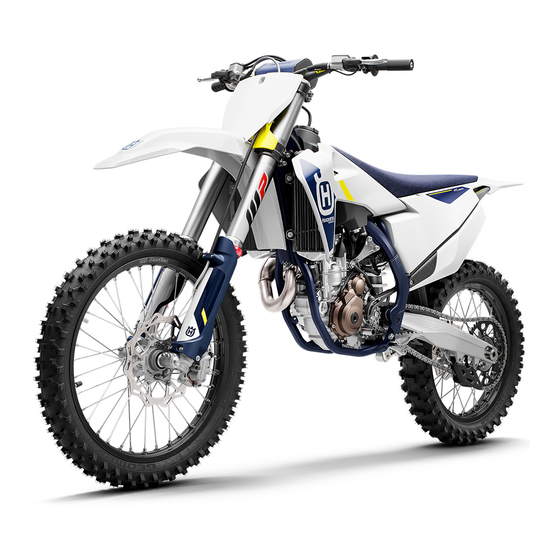
OWNER’S MANUAL 2022
FE 350
Art. no. 3402540en
Related Manuals for Husqvarna FE 350 2022
Summary of Contents for Husqvarna FE 350 2022
-
Page 1
OWNER’S MANUAL 2022 FE 350 Art. no. 3402540en… -
Page 3
DEAR HUSQVARNA MOTORCYCLES CUSTOMER Congratulations on your decision to purchase a Husqvarna motorcycle. You are now the owner of a state-of- DEAR HUSQVARNA MOTORCYCLES CUSTOMER the-art sports vehicle which, with appropriate care, will bring you pleasure for a long time to come. -
Page 4: Table Of Contents
TABLE OF CONTENTS TABLE OF CONTENTS 6.14 Opening fuel tank filler cap ….21 MEANS OF REPRESENTATION……6 6.15 Closing the fuel tank filler cap….. 22 Symbols used ……..6 6.16 Cold start button……… 22 Formats used ……..6 6.17 Idle speed adjusting screw ….
-
Page 5
TABLE OF CONTENTS Transporting……..40 12.9 Removing the lower triple clamp ..57 Refueling ……….40 12.10 Installing the lower triple clamp ..58 12.11 Checking the steering head bearing SERVICE SCHEDULE……..42 play …………. 60 10.1 Additional information……42 12.12 Adjusting the steering head bearing 10.2 Required work…….. -
Page 6
TABLE OF CONTENTS 13.2 Checking the brake discs ….89 TUNING THE ENGINE ……..123 13.3 Checking the front brake fluid level ..90 17.1 Checking the play in the throttle 13.4 Adding the front brake fluid …. 90 cable ……….123 13.5 Checking the front brake linings .. -
Page 7
TABLE OF CONTENTS INDEX OF SPECIAL TERMS ……157 LIST OF ABBREVIATIONS ……158 LIST OF SYMBOLS ……..159 29.1 Yellow and orange symbols….159 29.2 Green and blue symbols….159 INDEX …………..160… -
Page 8: Means Of Representation
1 MEANS OF REPRESENTATION Symbols used The meaning of specific symbols is described below. Indicates an expected reaction (e.g. of a work step or a function). Indicates an unexpected reaction (e.g. of a work step or a function). All work marked with this symbol requires specialist knowledge and technical understand- ing.
-
Page 9: Safety Advice 2
SAFETY ADVICE 2 Use definition – intended use (EU) This vehicle has been designed and built to withstand the normal stresses and strains of racing. This vehi- cle complies with the currently valid regulations and categories of the top international motorsports organi- zations.
-
Page 10: Degrees Of Risk And Symbols
2 SAFETY ADVICE Degrees of risk and symbols Danger Identifies a danger that will immediately and invariably lead to fatal or serious permanent injury if the appropriate measures are not taken. Warning Identifies a danger that is likely to lead to fatal or serious injury if the appropriate measures are not taken.
-
Page 11: Protective Clothing
– Always wear protective clothing that is in good condition and meets the legal regulations. In the interest of your own safety, Husqvarna Motorcycles recommends that you only operate the vehicle while wearing protective clothing. Work rules Unless specified otherwise, the ignition must be turned off during all work (models with ignition lock, models with remote key) or the engine must be at a standstill (models without ignition lock or remote key).
-
Page 12: Environment
Because motorcycles are not subject to the EU regulations governing the disposal of used vehicles, there are no legal regulations that pertain to the disposal of an end-of-life motorcycle. Your authorized Husqvarna Motor- cycles dealer will be glad to advise you.
-
Page 13: Important Notes 3
IMPORTANT NOTES 3 Manufacturer warranty, implied warranty The work prescribed in the service schedule must only be carried out in an authorized Husqvarna Motorcy- cles workshop and confirmed in the Husqvarna Motorcycles Dealer.net, as otherwise all warranty claims will be void. Damage or secondary damage caused by tampering with and/or conversions on the vehicle are not covered by the manufacturer warranty.
-
Page 14: Customer Service
3 IMPORTANT NOTES Customer service Your authorized Husqvarna Motorcycles dealer will be happy to answer any questions you may have regarding your vehicle and Husqvarna Motorcycles. A list of authorized Husqvarna Motorcycles dealers can be found on the Husqvarna Motorcycles website.
-
Page 15: View Of Vehicle 4
VIEW OF VEHICLE 4 View of vehicle, front left (example) F03489-10 Hand brake lever ( p. 17) Clutch lever ( p. 17) Fuel tank filler cap Air filter box cover Side stand ( p. 24) Engine number ( p. 15) Shift lever ( p.
-
Page 16: View Of Vehicle, Rear Right (Example)
4 VIEW OF VEHICLE View of vehicle, rear right (example) F03490-10 Fork compression adjuster Stop button ( p. 17) p. 18) (EU) Horn button ( Light switch ( p. 18) (EU) Turn signal switch ( p. 19) (EU) Start button ( p.
-
Page 17: Serial Numbers 5
SERIAL NUMBERS 5 Vehicle identification number The vehicle identification number is stamped on the right side of the steering head. 401945-10 Type label (EU) The Europe type label is fixed to the front of the steering head. The Canada type label is fixed to the front of the chest tube.
-
Page 18: Fork Part Number
5 SERIAL NUMBERS Fork part number The fork part number is stamped on the inner side of the fork stub. 401947-10 Shock absorber article number Shock absorber article number is stamped on the top of the shock absorber above the adjusting ring towards the engine side. H02222-10…
-
Page 19: Controls 6
CONTROLS 6 Clutch lever Clutch lever is fitted on the handlebar on the left. The clutch is activated hydraulically and adjusts itself automati- cally. F03491-10 Hand brake lever The hand brake lever is fitted on the right side of the handle- bar.
-
Page 20: Horn Button (Eu)
6 CONTROLS (US) The stop button is fitted on the left side of the handlebar. Possible states is in the basic position – In this position, • The stop button the ignition circuit is closed and the engine can be started. pressed –…
-
Page 21: Turn Signal Switch (Eu)
CONTROLS 6 Turn signal switch (EU) Turn signal switch is fitted on the left side of the handlebar. Possible states Turn signal off – The turn signal switch is in the cen- tral position. Left turn signal, on – The turn signal switch is turned to the left.
-
Page 22: Combination Switch
– The OBD has detected an error in the vehicle elec- tronics. Come safely to a halt, and contact an autho- rized Husqvarna Motorcycles workshop. The fuel level warning lamp lights up yellow – The fuel level has reached the reserve mark.
-
Page 23: Overview Of Indicator Lights (Us)
– The OBD has detected an error in the vehicle elec- tronics. Come safely to a halt, and contact an autho- rized Husqvarna Motorcycles workshop. The fuel level warning lamp lights up yellow – The fuel level has reached the reserve mark.
-
Page 24: Closing The Fuel Tank Filler Cap
6 CONTROLS 6.15 Closing the fuel tank filler cap – Mount fuel tank filler cap and turn it clockwise until the release button engages. Info Route fuel tank breather hose without kinks. F03500-10 6.16 Cold start button The cold start button is fitted to the bottom of the throttle valve body.
-
Page 25: Idle Speed Adjusting Screw
CONTROLS 6 6.17 Idle speed adjusting screw The idle setting of the throttle valve body substantially influences the vehicle’s starting behavior, a stable idle speed, and the vehi- cle’s response when the throttle is opened. An engine with a correctly set idle speed is easier to start than an engine with the idle speed set incorrectly.
-
Page 26: Foot Brake Lever
6 CONTROLS 6.19 Foot brake lever Foot brake lever is located in front of the right footrest. The rear brake is engaged with the foot brake lever. 401956-10 6.20 Side stand The side stand is attached to the left side of the vehicle. 401943-10 The side stand is used for parking the motorcycle.
-
Page 27: Locking The Steering (Eu)
CONTROLS 6 6.22 Locking the steering (EU) Note Danger of damage The parked vehicle can roll away or fall over. – Park the vehicle on a firm and level surface. – Park the vehicle. – Turn handlebar as far as possible to the right. –…
-
Page 28: Combination Instrument
Battery voltage of the combination instrument – Bat- tery voltage of the combination instrument is too low. Change combination instrument battery. Service – A service is due. Contact an authorized Husqvarna Motorcycles workshop. 401901-01 Setting the combination instrument Condition The motorcycle is stationary.
-
Page 29: Adjusting The Kilometers Or Miles
COMBINATION INSTRUMENT 7 – Wait for 5 seconds. Combination instrument changes to the next menu item. symbol flashes. – Press one of the buttons to select the 24 h display or 12 h display for the clock. 401911-01 – Wait for 5 seconds. Combination instrument changes to the next menu item.
-
Page 30: Setting The Clock
7 COMBINATION INSTRUMENT – Press and hold both buttons for 3 — 5 seconds. The Setup menu is displayed. The UNIT display flashes. – Press one of the buttons to select UNIT for the speed in kilo- meters KM/H or miles M/H. 401909-01 Setting the clock Condition…
-
Page 31: Speed, Time, And Dst Distance 1
COMBINATION INSTRUMENT 7 Switching off the service interval display – Press and hold the left button. off appears in the display. 401914-01 Speed, time, and DST distance 1 – Press one of the buttons until DST appears on the combina- tion instrument.
-
Page 32: Avg Average Speed, Art Operating Hours, And Odo Total Distance Covered
7 COMBINATION INSTRUMENT Press the left DST2 can be preset to a value between 0.0 button for 3 – and 39999.9 by pressing the buttons. 5 seconds. Press the Next display mode right button briefly. Press the DST2 is reset to 0.0. right button for 3 –…
-
Page 33: Preparing For Use 8
When using your motorcycle, remember that others may feel disturbed by excessive noise. – Make sure that the pre-sale inspection work has been carried out by an authorized Husqvarna Motorcycles workshop. You will receive a delivery certificate when the vehicle is handed over.
-
Page 34: Running-In The Engine
8 PREPARING FOR USE – Adjust basic position of the hand brake lever. ( p. 89) – Adjust the basic position of the foot brake lever. p. 95) – Adjust the basic position of the shift lever. p. 128) – Get used to the handling characteristics of the motorcycle on a suitable surface before undertaking more challenging trips.
-
Page 35: Starting Power Of Lithium-Ion Batteries At Low Temperatures
Riding at low temperatures and in snow. ( p. 35) Preparing the vehicle for riding on dry sand – Mount the air filter dust cover. Air filter dust cover (79006920000) Info Read the fitting instructions for Husqvarna Motorcy- cles accessories. 102136-01…
-
Page 36: Preparing The Vehicle For Riding On Wet Sand
8 PREPARING FOR USE – Mount the air filter sand cover. Air filter sand cover (79006922000) Info Read the fitting instructions for Husqvarna Motorcy- cles accessories. 102138-01 – Clean the chain. – Mount the steel sprocket. – Grease the chain.
-
Page 37: Preparing Vehicle For High Temperatures Or Slow Riding
Straighten bent radiator fins carefully. – Check the coolant level. ( p. 120) Preparing the vehicle for low temperatures or snow – Mount the air filter rain cover. Air filter rain cover (79006921000) Info Read the fitting instructions for Husqvarna Motorcy- cles accessories. 102137-01…
-
Page 38: Riding Instructions
9 RIDING INSTRUCTIONS Checks and maintenance measures when preparing for use Info Before every trip, check the condition of the vehicle and ensure that it is safe to operate. The vehicle must be in perfect technical condition when it is being operated. –…
-
Page 39: Activating Traction Control
RIDING INSTRUCTIONS 9 – Take the motorcycle off side stand and secure the side stand with rubber strap – Shift the transmission into neutral. (EU) – Turn the emergency OFF switch to the position Condition Ambient temperature: < 20 °C (< 68 °F) –…
-
Page 40: Starting Off
Danger of accidents A spongy pressure point on the front or rear brake reduces braking efficiency. – Check the brake system and do not continue riding until the problem is eliminated. (Your authorized Husqvarna Motorcycles workshop will be glad to help.)
-
Page 41: Stopping, Parking
RIDING INSTRUCTIONS 9 Warning Danger of accidents Moisture and dirt impair the brake system. – Brake carefully several times to dry out and remove dirt from the brake linings and the brake discs. – On sandy, wet, or slippery surfaces, use the rear brake. –…
-
Page 42: Transporting
In some countries and regions, the available fuel quality and cleanliness may not be sufficient. This will result in problems with the fuel system. – Refuel only with clean fuel that meets the specified standards. (Your authorized Husqvarna Motorcycles workshop will be glad to help.)
-
Page 43
RIDING INSTRUCTIONS 9 Note Environmental hazard Improper handling of fuel is a danger to the environment. – Do not allow fuel to enter the groundwater, the soil, or the sewage system. – Switch off engine. – Open fuel tank filler cap. ( p. -
Page 44: 10 Service Schedule
Different service intervals may apply in your country, depending on the local operating conditions. Individual service intervals and scopes may change in the course of technical developments. The most up-to- date service schedule can always be found on Husqvarna Motorcycles Dealer.net. Your authorized Husqvarna Motorcycles dealer will be glad to advise you.
-
Page 45: Recommended Work
● Final check: Check the vehicle is roadworthy and take a test ride. ○ ● ● ● ● Read out the fault memory after the test ride using the Husqvarna Motorcycles diag- nostics tool. ○ ● ● ● ● Make a service entry in Husqvarna Motorcycles Dealer.net.
-
Page 46
10 SERVICE SCHEDULE every 48 months every 12 months Every 135 operating hours Every 70 operating hours when used for motorsports After 20 operating hours After 10 operating hours ● ● Perform engine service including removing and installing the engine. (Change the spark plug and spark plug connector. -
Page 47: Tuning The Chassis 11
The shock absorber is filled with highly compressed nitrogen. – Please follow the description provided. (Your authorized Husqvarna Motorcycles workshop will be glad to help.) Info The effect of the low-speed compression adjuster can be seen in slow to normal compression of the…
-
Page 48: Adjusting The High-Speed Compression Damping Of The Shock Absorber
The shock absorber is filled with highly compressed nitrogen. – Please follow the description provided. (Your authorized Husqvarna Motorcycles workshop will be glad to help.) Info The effect of the high speed compression adjuster can be seen in the fast compression of the shock absorber.
-
Page 49: Adjusting The Rebound Damping Of The Shock Absorber
Risk of injury Parts of the shock absorber will move around if the shock absorber is detached incor- rectly. The shock absorber is filled with highly compressed nitrogen. – Please follow the description provided. (Your authorized Husqvarna Motorcycles workshop will be glad to help.) – Turn adjusting screw clockwise up to the last perceptible click.
-
Page 50: Checking The Static Sag Of The Shock Absorber
11 TUNING THE CHASSIS Finishing work – Remove the motorcycle from the lift stand. ( p. 54) 11.7 Checking the static sag of the shock absorber – Measure dimension of rear wheel unloaded. ( p. 47) – Hold the motorcycle upright with aid of an assistant. –…
-
Page 51: Adjusting The Spring Preload Of The Shock Absorber
The shock absorber is filled with highly compressed nitrogen. – Please follow the description provided. (Your authorized Husqvarna Motorcycles workshop will be glad to help.) Info Before changing the spring preload, make a note of the present setting, e.g., by measuring the spring length.
-
Page 52: Adjusting The Riding Sag
11 TUNING THE CHASSIS 11.10 Adjusting the riding sag Preparatory work – Raise the motorcycle with a lift stand. ( p. 54) – Remove the shock absorber. p. 63) – After removing the shock absorber, clean it thoroughly. Main work –…
-
Page 53: Adjusting The Compression Damping Of The Fork
TUNING THE CHASSIS 11 11.12 Adjusting the compression damping of the fork Info The hydraulic compression damping determines the fork suspension behavior. – Turn white adjuster clockwise as far as it will go. Info Adjuster is located at the upper end of the left fork leg.
-
Page 54: Adjusting The Spring Preload Of The Fork
11 TUNING THE CHASSIS Info Turn clockwise to increase the damping; turn counterclockwise to reduce damping when the shock absorber rebounds. 11.14 Adjusting the spring preload of the fork Preparatory work – Raise the motorcycle with a lift stand. ( p.
-
Page 55: Adjusting The Handlebar Position
TUNING THE CHASSIS 11 11.16 Adjusting the handlebar position Warning Danger of accidents A repaired handlebar poses a safety risk. If the handlebar is bent or straightened, the material becomes fatigued. The handlebar may break as a result. – Change the handlebar if the handlebar is damaged or bent. –…
-
Page 56: 12 Service Work On The Chassis
12 SERVICE WORK ON THE CHASSIS 12.1 Raising the motorcycle with a lift stand Note Danger of damage The parked vehicle can roll away or fall over. – Park the vehicle on a firm and level surface. – Raise the motorcycle at the frame underneath the engine. Lift stand (81329955100) Neither wheel is in contact with the ground.
-
Page 57: Cleaning The Dust Boots Of The Fork Legs
SERVICE WORK ON THE CHASSIS 12 12.4 Cleaning the dust boots of the fork legs Preparatory work – Raise the motorcycle with a lift stand. ( p. 54) – Remove the fork protector. ( p. 55) Main work – Push dust boots of both fork legs downward.
-
Page 58: Installing The Fork Protector
12 SERVICE WORK ON THE CHASSIS 12.6 Installing the fork protector – Position the fork protector on the left fork leg. Mount and tighten screws Guideline Remaining screws, 10 Nm (7.4 lbf ft) chassis – Position the brake line, wiring harness, and clamp. Mount and tighten screws –…
-
Page 59: Installing The Fork Legs
SERVICE WORK ON THE CHASSIS 12 12.8 Installing the fork legs Main work – Position the fork legs. Bleeder screws are positioned toward the front. Info The compression damping is located in left fork leg COMP (white adjuster). The rebound damping is located in right fork leg REB (red adjuster).
-
Page 60: Installing The Lower Triple Clamp
12 SERVICE WORK ON THE CHASSIS Main work – Remove screw – Remove screw – Open cable holder in front of the left radiator and detach the clutch line. – Take off the upper triple clamp with the handlebar and set aside.
-
Page 61
SERVICE WORK ON THE CHASSIS 12 – Position the upper triple clamp with the handlebar. – Mount screw , but do not tighten yet. – Mount the clutch line with cable holder S03552-11 – Position the fork legs. Bleeder screws are positioned toward the front. -
Page 62: Checking The Steering Head Bearing Play
Danger of accidents Incorrect steering head bearing play impairs the handling characteristic and damages components. – Correct incorrect steering head bearing play immediately. (Your authorized Husqvarna Motorcycles workshop will be glad to help.) Info If the vehicle is operated for a lengthy period with play in the steering head bearing, the bearings and the bearing seats in the frame can become damaged over time.
-
Page 63: Adjusting The Steering Head Bearing Play
SERVICE WORK ON THE CHASSIS 12 Main work – Move the handlebar to the straight-ahead position. Move the fork legs to and fro in the direction of travel. Play should not be detectable on the steering head bear- ing. » If there is detectable play: –…
-
Page 64: Lubricating The Steering Head Bearing
12 SERVICE WORK ON THE CHASSIS 12.13 Lubricating the steering head bearing – Remove the lower triple clamp. p. 57) – Install the lower triple clamp. p. 58) Info The steering head bearing is cleaned and lubricated in the course of removal and installation of the lower triple clamp.
-
Page 65: Installing Front Fender
SERVICE WORK ON THE CHASSIS 12 12.15 Installing front fender Main work – Position front fender. Mount and tighten screws Guideline Remaining screws, 10 Nm (7.4 lbf ft) chassis – Mount and tighten screws Guideline Remaining screws, 10 Nm (7.4 lbf ft) chassis H03691-10 Finishing work…
-
Page 66
12 SERVICE WORK ON THE CHASSIS – Press angle lever toward the rear. – Press linkage lever downward. H03694-10 (EU) – Disconnect the plug-in connector of the brake light switch. F03465-10 – Remove screws – Pull off foot brake cylinder from the push rod. F03466-10 –… -
Page 67: Installing The Shock Absorber
SERVICE WORK ON THE CHASSIS 12 – Hold the shock absorber and remove screw – Remove the shock absorber carefully at the bottom. F03469-10 12.17 Installing the shock absorber Main work – Carefully position the shock absorber into the vehicle from the bottom.
-
Page 68: Removing The Seat
12 SERVICE WORK ON THE CHASSIS – Position the foot brake cylinder. Push rod engages in the foot brake cylinder. The dust boot is correctly positioned. – Mount and tighten screws Guideline Remaining screws, 10 Nm (7.4 lbf ft) chassis F03472-10 –…
-
Page 69: Mounting The Seat
SERVICE WORK ON THE CHASSIS 12 Main work – Remove screw with the bushing. – Pull seat back and lift it off. S03559-10 12.19 Mounting the seat Main work – Mount the front of the seat on the collar bushing of the fuel tank and the rear in the bracket.
-
Page 70: Removing The Air Filter Box Cover
12 SERVICE WORK ON THE CHASSIS 12.20 Removing the air filter box cover – Pull off the air filter box cover sideways in areas and take off toward the rear. F02311-10 12.21 Installing the air filter box cover – Attach catch of the air filter box in area and push for- ward.
-
Page 71: Installing The Air Filter
SERVICE WORK ON THE CHASSIS 12 Main work – Detach retaining tab . Remove air filter with air filter sup- port. – Remove air filter from air filter support. F02313-10 12.23 Installing the air filter Main work – Mount the clean air filter on the air filter support. –…
-
Page 72: Removing The Right Side Cover
12 SERVICE WORK ON THE CHASSIS Main work – Wash the air filter thoroughly in special cleaning liquid and allow it to dry properly. Air filter cleaner ( p. 154) Info Only press the air filter to dry it, never wring it out. –…
-
Page 73: Installing The Right Side Cover
SERVICE WORK ON THE CHASSIS 12 12.26 Installing the right side cover Main work – Attach side cover with the holding lugs from below and push upward. – Engage the side cover in areas F03474-10 Finishing work – Mount the seat. ( p.
-
Page 74: Installing The Main Silencer
12 SERVICE WORK ON THE CHASSIS 12.28 Installing the main silencer Main work (EU) – Position the catalytic converter in the main silencer. S02101-10 – Position the main silencer. – Mount screws , but do not tighten yet. – Attach spring Spring hook (50305017000C1) –…
-
Page 75
SERVICE WORK ON THE CHASSIS 12 S03542-10 Main work – Remove all screws, take off silencer cap with O-ring Info Do not remove the glass fiber yarn filling. Caution Danger to health Soot particles irritate the eyes and mucuous membranes. – Wear suitable breathing and eye protection when cleaning the main silencer and carbon screen. -
Page 76: Changing The Glass Fiber Yarn Filling In The Main Silencer
12 SERVICE WORK ON THE CHASSIS 12.30 Changing the glass fiber yarn filling in the main silencer Warning Danger of burns The exhaust system gets very hot when the vehicle is driven. – Allow the exhaust system to cool down before performing any work on the vehicle. Info Over time, the fibers of the glass fiber yarn filling escape and the damper «burns»…
-
Page 77: Removing The Fuel Tank
SERVICE WORK ON THE CHASSIS 12 (US) – Remove all the screws on the main silencer. – Take off silencer cap with the filter and O-ring – Remove glass fiber yarn filling from main silencer – Clean the parts that need to be reinstalled and check for damage.
-
Page 78
12 SERVICE WORK ON THE CHASSIS – Remove the seat. ( p. 66) – Remove the right side cover. ( p. 70) Main work – Unplug connector of the fuel pump. – Clean quick release coupling thoroughly with compressed air. Info Under no circumstances should dirt enter into the fuel line. -
Page 79: Installing The Fuel Tank
SERVICE WORK ON THE CHASSIS 12 12.32 Installing the fuel tank Danger Fire hazard Fuel is highly flammable. The fuel in the fuel tank expands when warm and can escape if overfilled. – Do not fuel the vehicle in the vicinity of open flames or lit cigarettes. –…
-
Page 80: Checking For Chain Dirt Accumulation
12 SERVICE WORK ON THE CHASSIS (EU) – Position the horn with the horn bracket. – Mount and tighten screws Guideline Remaining screws, 10 Nm (7.4 lbf ft) chassis H03705-11 – Plug in connector for the fuel pump. – Remove the wash cap set. –…
-
Page 81: Cleaning The Chain
SERVICE WORK ON THE CHASSIS 12 12.34 Cleaning the chain Warning Danger of accidents Lubricants on the tires reduces the road grip. – Remove lubricants from the tires using a suitable cleaning agent. Warning Danger of accidents Oil or grease on the brake discs reduces the braking effect. –…
-
Page 82: Adjusting The Chain Tension
12 SERVICE WORK ON THE CHASSIS Main work – Pull the chain at the end of the chain sliding piece upward to measure chain tension Info Lower chain section must be taut. When the chain guard is mounted, it must be possi- ble to pull up the chain at least to the point where it makes contact with chain guard Chain wear is not always even, so you should repeat…
-
Page 83: Checking The Chain, Rear Sprocket, Engine Sprocket, And Chain Guide
SERVICE WORK ON THE CHASSIS 12 Main work – Loosen nut – Loosen nuts – Adjust the chain tension by turning adjusting screws left and right. Guideline Chain tension 55 … 58 mm (2.17 … 2.28 in) Turn adjusting screws on the left and right so that the markings on the left and right chain adjusters are in the same position relative to reference marks…
-
Page 84
12 SERVICE WORK ON THE CHASSIS – Pull on the top section of the chain with the specified weight Guideline Weight of chain wear mea- 10 … 15 kg (22 … 33 lb.) surement – Measure distance of 18 chain rollers in the lower chain section. -
Page 85
SERVICE WORK ON THE CHASSIS 12 – Check chain sliding piece for wear. » If the lower edge of the chain pins is in line with or below the chain sliding piece: – Change the chain sliding piece. – Check that the chain sliding piece is firmly seated. »… -
Page 86: Checking The Frame
If the link fork exhibits damage, cracking, or deformation: – Change the link fork. Info Always replace a damaged link fork. Repair of the link fork is not authorized by Husqvarna Motorcycles. 401520-01 12.40 Checking the throttle cable routing Preparatory work –…
-
Page 87: Checking The Rubber Grip
SERVICE WORK ON THE CHASSIS 12 Finishing work – Install the fuel tank. p. 77) – Install the right side cover. ( p. 71) – Mount the seat. ( p. 67) – Install the air filter box cover. ( p. 68) 12.41 Checking the rubber grip –…
-
Page 88: Checking/Correcting The Fluid Level Of Hydraulic Clutch
12 SERVICE WORK ON THE CHASSIS Info Turn the adjusting screw clockwise to increase the distance between the clutch lever and the handlebar. Turn the adjusting screw counterclockwise to decrease the distance between the clutch lever and the handlebar. The range of adjustment is limited. Turn the adjusting screw by hand only, and do not apply any force.
-
Page 89: Changing The Hydraulic Clutch Fluid
SERVICE WORK ON THE CHASSIS 12 Info Immediately clean up any brake fluid that has over- flowed or spilled with water. 12.44 Changing the hydraulic clutch fluid Warning Skin irritation Brake fluid causes skin irritation. – Keep brake fluid out of the reach of children. –…
-
Page 90: Removing The Engine Guard
12 SERVICE WORK ON THE CHASSIS – Now inject fluid into the system until it escapes from the openings of the master cylinder without bubbles. – Occasionally extract the fluid from the master cylinder reser- voir to prevent overflowing. – Remove the bleeding syringe.
-
Page 91: Brake System 13
Warning Danger of accidents Worn-out brake discs reduce the braking effect. – Make sure that worn-out brake discs are replaced immediately. (Your authorized Husqvarna Motor- cycles workshop will be glad to help.) – Check the front and rear brake disc thickness at multiple…
-
Page 92: Checking The Front Brake Fluid Level
– Make sure that brake fluid for the front and rear brake is changed in accordance with the service schedule. (Your authorized Husqvarna Motorcycles workshop will be glad to help.) – Move the brake fluid reservoir mounted on the handlebar to a horizontal position.
-
Page 93: Checking The Front Brake Linings
Checking the front brake linings Warning Danger of accidents Worn-out brake linings reduce the braking effect. – Ensure that worn-out brake linings are replaced immediately. (Your authorized Husqvarna Motorcy- cles workshop will be glad to help.) – Check the brake linings for minimum thickness ≥…
-
Page 94: Changing The Brake Linings Of The Front Brake
Danger of accidents Brake linings which have not been approved alter the braking efficiency. Not all brake linings are tested and approved for Husqvarna motorcycles. The structure and friction coefficient of the brake linings, and thus their brake power, may vary greatly from that of original brake linings.
-
Page 95
BRAKE SYSTEM 13 – Move the brake fluid reservoir mounted on the handlebar to a horizontal position. – Remove screws – Take off cover with membrane F03508-10 – Manually press the brake caliper toward the brake disc to push back the brake pistons. Ensure that brake fluid does not flow out of the brake fluid reservoir, extract some if neces- sary. -
Page 96: Checking The Free Travel Of Foot Brake Lever
13 BRAKE SYSTEM – Add brake fluid up to level Guideline 5 mm (0.2 in) Level (brake fluid level below reservoir rim) Brake fluid DOT 4 / DOT 5.1 ( p. 152) – Position cover with membrane – Mount and tighten screws Info Use water to immediately clean up any brake fluid that has overflowed or spilled.
-
Page 97: Adjusting The Basic Position Of The Foot Brake Lever
Warning Danger of accidents Old brake fluid reduces the braking effect. – Make sure that brake fluid for the front and rear brake is changed in accordance with the service schedule. (Your authorized Husqvarna Motorcycles workshop will be glad to help.)
-
Page 98: Adding Rear Brake Fluid
Danger of accidents Old brake fluid reduces the braking effect. – Make sure that brake fluid for the front and rear brake is changed in accordance with the service schedule. (Your authorized Husqvarna Motorcycles workshop will be glad to help.) Note Environmental hazard Hazardous substances cause environmental damage.
-
Page 99: Checking The Rear Brake Linings
Checking the rear brake linings Warning Danger of accidents Worn-out brake linings reduce the braking effect. – Ensure that worn-out brake linings are replaced immediately. (Your authorized Husqvarna Motorcy- cles workshop will be glad to help.) – Check the brake linings for minimum thickness ≥…
-
Page 100
Danger of accidents Brake linings which have not been approved alter the braking efficiency. Not all brake linings are tested and approved for Husqvarna motorcycles. The structure and friction coefficient of the brake linings, and thus their brake power, may vary greatly from that of original brake linings. -
Page 101
BRAKE SYSTEM 13 – Remove the brake linings. – Clean the brake caliper and the brake caliper bracket. – Check that spring plate in the brake caliper and brake pad sliding plate in the brake caliper bracket are fitted correctly. –… -
Page 102: 14 Wheels, Tires
14 WHEELS, TIRES 14.1 Removing the front wheel Preparatory work – Raise the motorcycle with a lift stand. ( p. 54) Main work – Manually press the brake caliper toward the brake disc to push back the brake pistons. Info Make sure that you do not press the brake caliper against the spokes when pushing back the brake pis- tons.
-
Page 103: Installing The Front Wheel
WHEELS, TIRES 14 14.2 Installing the front wheel Warning Danger of accidents Oil or grease on the brake discs reduces the braking effect. – Always keep the brake discs free of oil and grease. – Clean the brake discs with brake cleaner when necessary. –…
-
Page 104: Installing The Rear Wheel
14 WHEELS, TIRES Main work – Manually press the brake caliper toward the brake disc to push back the brake piston. Info Make sure that you do not press the brake caliper against the spokes when pushing back the brake pis- ton.
-
Page 105
WHEELS, TIRES 14 Main work – Check the wheel bearing for damage and wear. » If the wheel bearing is damaged or worn: – Change the rear wheel bearing. – Clean and grease shaft seal rings and contact surfaces of the spacers. Long-life grease ( p. -
Page 106: Checking The Tire Condition
Checking the tire condition Info Only mount tires approved and/or recommended by Husqvarna Motorcycles. Other tires could have a negative effect on handling characteristics. The type, condition, and pressure of the tires all have a major impact on the handling characteristic of the motorcycle.
-
Page 107: Checking Spoke Tension
Other spokes will become looser as a result. – Check spoke tension regularly, and in particular on a new vehicle. (Your authorized Husqvarna Motorcycles workshop will be glad to help.) –…
-
Page 108: 15 Electrical System
15 ELECTRICAL SYSTEM 15.1 Removing the 12-V battery Note Environmental hazard 12 V batteries contain environmentally hazardous materials. – Do not dispose of 12 V batteries as household waste. – Dispose of 12 V batteries at a collection point for used batteries. Note Environmental hazard Hazardous substances cause environmental damage.
-
Page 109: Installing The 12-V Battery
ELECTRICAL SYSTEM 15 – Detach wiring harness , disconnect relays and hang them to the side. S03579-10 – Remove screw and unhook the holding bracket. – Lift out the 12-V battery. S03582-10 15.2 Installing the 12-V battery Main work – Insert the 12-V battery into the battery compartment with the terminals facing forward and secure with holding bracket 12-V battery (HJTZ5S-FP-C) (…
-
Page 110
15 ELECTRICAL SYSTEM – Place the relays on the holding bracket and attach wiring harness S03579-11 – Attach starter relay and fuse box to the holding bracket. S03578-11 – Connect positive cable to the 12-V battery. Guideline Screw, battery termi- 2.5 Nm (1.84 lbf ft) Info Contact disk… -
Page 111: Charging The 12-V Battery
ELECTRICAL SYSTEM 15 15.3 Charging the 12-V battery Warning Risk of injury 12 V batteries contain harmful substances. – Keep 12 V batteries out of the reach of children. – Keep sparks and open flames away from 12 V batteries. – Only charge 12 V batteries in well-ventilated rooms.
-
Page 112: Changing Main Fuse
12-V battery with this battery charger. The charg- ing time may be longer at low temperatures. This battery charger is only suitable for lithium iron phosphate batteries. Read the accompanying instruc- tions for Husqvarna Motorcycles accessories. Info Never remove cover –…
-
Page 113: Changing The Fuses Of Individual Electrical Power Consumers
ELECTRICAL SYSTEM 15 Main work – Pull starter relay from the holder. S03588-10 – Take off protection caps – Remove faulty main fuse Info A faulty fuse has a burned-out fuse wire A spare fuse is located in the starter relay. –…
-
Page 114
15 ELECTRICAL SYSTEM Guideline (EU) Fuse 1 – 10 A – EFI control unit, lambda sensor, combi- nation instrument, combination switch (optional), elec- tronic fuel injection, diagnostics connector, fuel vapor retention system, fuse 4 Fuse 2 ‑ 10 A ‑ high beam, low beam, position light, tail light, license plate lamp Fuse 3 — 10 A — radiator fan, horn, brake light, turn sig- Fuse 4 — 5 A — fuel pump… -
Page 115: Removing The Headlight Mask With The Headlight
ELECTRICAL SYSTEM 15 15.6 Removing the headlight mask with the headlight – Loosen rubber straps . Slide the headlight mask up and swing it forward. H03749-10 – Remove screw – Detach the brake line and wiring harness from the headlight mask.
-
Page 116
15 ELECTRICAL SYSTEM (US) – Join plug-in connector H03751-11 – Position the brake line and the wiring harness in the cable guide. – Mount and tighten screw – Position the headlight mask. The holding lugs engage in the fender. H03752-10 –… -
Page 117: Changing The Headlight Bulb
ELECTRICAL SYSTEM 15 15.8 Changing the headlight bulb Note Damage to reflector Grease on the reflector reduces the light intensity. Grease on the bulb will evaporate due to the heat and be deposited on the reflector. – Clean and degrease the bulbs before mounting. –…
-
Page 118: Checking The Headlight Setting
15 ELECTRICAL SYSTEM Main work – Remove the screw on the rear of the turn signal housing. – Carefully remove turn signal glass – Lightly squeeze orange cap in the area of the holding lugs and take it off. – Press the turn signal bulb lightly into the socket, turn it coun- terclockwise by about 30°, and pull it out of the socket.
-
Page 119: Adjust The Headlight Range
ELECTRICAL SYSTEM 15 15.11 Adjust the headlight range. Preparatory work – Check the headlight setting. ( p. 116) Main work – Loosen screw – Adjust the headlight range by pivoting the headlight. Guideline The boundary between light and dark must be exactly on the lower mark for a motorcycle with rider (instructions on how to apply the mark: Checking the headlight setting).
-
Page 120: Diagnostics Connector
15 ELECTRICAL SYSTEM Finishing work – Install the headlight mask with the headlight. ( p. 113) – Check the headlight setting. ( p. 116) – Set the combination instrument. ( p. 26) 15.13 Diagnostics connector Diagnostics connector is located under the seat. H00933-12…
-
Page 121: Cooling System 16
COOLING SYSTEM 16 16.1 Cooling system Water pump in the engine ensures forced circulation of the coolant. The pressure resulting from the warming of the cooling system is regulated by a valve in radiator cap . This ensures that operat- ing the vehicle at the specified coolant temperature will not result in a risk of malfunctions.
-
Page 122: Checking The Coolant Level
16 COOLING SYSTEM Coolant ( p. 152) – Mount the radiator cap. 16.3 Checking the coolant level Warning Danger of scalding During motorcycle operation, the coolant gets very hot and is under pressure. – Do not open the radiator, the radiator hoses or other cooling system components if the engine or the cooling system are at operating temperature.
-
Page 123: Refilling With Coolant
COOLING SYSTEM 16 Warning Danger of poisoning Coolant is toxic and a health hazard. – Keep coolant out of the reach of children. – Do not allow coolant to come into contact with the skin, the eyes and clothing. – Consult a doctor immediately if coolant is swallowed. –…
-
Page 124: Changing The Coolant
16 COOLING SYSTEM – Check the coolant level. ( p. 120) 16.6 Changing the coolant Warning Danger of scalding During motorcycle operation, the coolant gets very hot and is under pressure. – Do not open the radiator, the radiator hoses or other cooling system components if the engine or the cooling system are at operating temperature.
-
Page 125: Tuning The Engine 17
TUNING THE ENGINE 17 17.1 Checking the play in the throttle cable – Check the throttle grip for smooth operation. – Move the handlebar to the straight-ahead position. Turn the throttle grip back and forth slightly and determine the play in throttle cable Play in throttle cable 3 ……
-
Page 126: Adjusting The Characteristic Map Of The Throttle Response
17 TUNING THE ENGINE Main work – Move the handlebar to the straight-ahead position. – Push back sleeve – Loosen nut – Turn adjusting screw in as far as possible. – Loosen nut – Push cold start button all the way to the stop. –…
-
Page 127
TUNING THE ENGINE 17 – Remove guide plate from handle tube – Position the required guide plate on the grip tube. Guideline The label OUTSIDE must be visible. Marking must be positioned at marking Grey guide plate (79002014000) Alternative 1 Black guide plate (79002014100) Info The gray guide plate opens the throttle valve more… -
Page 128: Changing The Mapping
Adjusting the idle speed Warning Danger of accidents The engine may go out spontaneously if the idle speed is set too low. – Set the idle speed to the specified value. (Your authorized Husqvarna Motorcycles workshop will be glad to help.)
-
Page 129: Programming The Throttle Valve Position
TUNING THE ENGINE 17 – Run the engine until warm. The cold start button is deactivated – The cold start but- ton is in its basic position. ( p. 22) Danger Danger of poisoning Exhaust gases are toxic and inhaling them may result in unconsciousness and death.
-
Page 130: Checking The Basic Position Of The Shift Lever
17 TUNING THE ENGINE 17.7 Checking the basic position of the shift lever Info When driving, the shift lever must not touch the rider’s boot when in the basic position. When the shift lever keeps touching the boot, the transmission will be subject to an excessive load. –…
-
Page 131: Service Work On The Engine 18
SERVICE WORK ON THE ENGINE 18 18.1 Changing the fuel screen Danger Fire hazard Fuel is highly flammable. The fuel in the fuel tank expands when warm and can escape if overfilled. – Do not fuel the vehicle in the vicinity of open flames or lit cigarettes. –…
-
Page 132: Checking The Engine Oil Level
18 SERVICE WORK ON THE ENGINE Danger Danger of poisoning Exhaust gases are toxic and inhaling them may result in unconsciousness and death. – Always make sure there is sufficient ventilation when running the engine. – Use effective exhaust extraction when starting or running the engine in an enclosed space.
-
Page 133
SERVICE WORK ON THE ENGINE 18 Info Drain the engine oil with the engine at operating temperature. Preparatory work – Park the motorcycle on a level surface. – Remove the engine guard. ( p. 88) Main work – Position an appropriate container under the engine. –… -
Page 134
18 SERVICE WORK ON THE ENGINE – Remove screws . Remove the oil filter cover with the O- ring. V01397-10 – Pull oil filter out of the oil filter housing. Lock ring plier (51012011000) – Allow the engine oil to drain completely. –… -
Page 135: Adding Engine Oil
Engine oil (SAE 10W/50) ( p. 152) Info In order to achieve optimal engine oil performance, it is not advisable to mix different engine oils. Husqvarna Motorcycles recommends changing the engine oil. – Mount and tighten the filler plug together with the O-ring. Danger Danger of poisoning Exhaust gases are toxic and…
-
Page 136: 19 Cleaning, Care
19 CLEANING, CARE 19.1 Cleaning the motorcycle Note Material damage Components become damaged or destroyed if a pressure cleaner is used incorrectly. The high pressure forces water into the electrical components, connectors, throttle cables, and bearings, etc. Pressure which is too high causes malfunctions and destroys components. –…
-
Page 137: Checks And Maintenance Steps For Winter Operation
CLEANING, CARE 19 – Treat bare metal (except for brake discs and the exhaust sys- tem) with a corrosion inhibitor. Preserving materials for paints, metal and rubber p. 154) – Treat all plastic parts and powder-coated parts with a mild cleaning and care product.
-
Page 138: 20 Storage
– Store the vehicle in a dry location that is not subject to large fluctuations in temperature. Info Husqvarna Motorcycles recommends raising the motorcycle. – Raise the motorcycle with a lift stand. ( p. 54) –…
-
Page 139: Preparing For Use After Storage
STORAGE 20 Info Avoid running the engine for a short time only. Since the engine cannot warm up properly, the water vapor produced during combustion condenses and causes valves and the exhaust system to rust. 20.2 Preparing for use after storage –…
-
Page 140: 21 Troubleshooting
Check the electrical system. – Error in the electronic fuel Read out the fault memory using the injection Husqvarna Motorcycles diagnostics tool. – Engine does not speed up Error in the electronic fuel Read out the fault memory using the…
-
Page 141
– Read out the fault memory using the Husqvarna Motorcycles diagnostics tool. – High oil consumption Engine vent hose bent Route the vent hose without bends or replace it if necessary. -
Page 142
21 TROUBLESHOOTING Faults Possible cause Action – The high beam, low beam, tail Fuse 2 blown Change the fuses of individual electri- light, position light, and license cal power consumers. ( p. 111) plate lamp are not working – The horn, brake light, turn sig- Fuse 3 blown Change the fuses of individual electri- nal, and radiator fan are not… -
Page 143: Blink Code 22
BLINK CODE 22 Info The blink codes are only displayed by the derestricted version of the vehicle. Blink code for malfunc- tion indicator lamp 02a Malfunction indicator lamp flashes 2x per second Error level condition Throttle valve position programming necessary Blink code for malfunc- tion indicator lamp 02 Malfunction indicator lamp flashes 2x short…
-
Page 144
22 BLINK CODE Blink code for malfunc- tion indicator lamp 33 Malfunction indicator lamp flashes 3x long, 3x short Error level condition Injector cylinder 1 — circuit fault Blink code for malfunc- tion indicator lamp 37 Malfunction indicator lamp flashes 3x long, 7x short Error level condition Ignition coil 1, cylinder 1 — circuit fault Blink code for malfunc-… -
Page 145: Technical Data 23
TECHNICAL DATA 23 23.1 Engine Design 1-cylinder 4-stroke engine, water-cooled Displacement 349.7 cm³ (21.34 cu in) Stroke 57.5 mm (2.264 in) Bore 88 mm (3.46 in) Compression ratio 13.5:1 Idle speed 1,950 … 2,050 rpm Control DOHC, four valves controlled via cam lever, drive via timing chain Valve diameter, intake 36.3 mm (1.429 in)
-
Page 146: Engine Tightening Torques
23 TECHNICAL DATA 23.2 Engine tightening torques Nozzle, crank chamber ventilation 2 Nm (1.5 lbf ft) ® Loctite 243™ Oil nozzle for clutch lubrication 2 Nm (1.5 lbf ft) ® Loctite 243™ Oil nozzle for conrod bearing 2 Nm (1.5 lbf ft) ®…
-
Page 147
TECHNICAL DATA 23 Screw, oil filter cover 10 Nm (7.4 lbf ft) Screw, shift drum locating 10 Nm (7.4 lbf ft) ® Loctite 243™ Screw, shift lever 14 Nm (10.3 lbf ft) ® Loctite 243™ Screw, starter motor 10 Nm (7.4 lbf ft) Screw, starter motor — intermedi- 10 Nm (7.4 lbf ft) ®… -
Page 148: Capacities
23 TECHNICAL DATA Nut, inner clutch hub M18x1.5 100 Nm (73.8 lbf ft) ® Loctite 243™ Nut, primary gear wheel M18LHx1.5 120 Nm (88.5 lbf ft) ® Loctite 243™ Screw plug, oil screen M20x1.5 15 Nm (11.1 lbf ft) Plug, timing chain tensioner M24x1.5 40 Nm (29.5 lbf ft) Screw, alternator cover…
-
Page 149: Electrical System
80/100 — 21 M/C 51M TT 110/100 — 18 M/C 64M TT Dunlop GEOMAX AT 81 F Dunlop GEOMAX AT81 The tires specified represent one of the possible series production tires. Additional information is available in the Service section under: www.husqvarna-motorcycles.com…
-
Page 150: Fork
23 TECHNICAL DATA 23.7 Fork Fork article number 0266C169V401000 Fork WPXPLOR 5548 Compression damping Comfort 18 clicks Standard 15 clicks Sport 12 clicks Rebound damping Comfort 18 clicks Standard 15 clicks Sport 12 clicks Spring preload – preload adjuster Comfort Standard Sport Spring length with preload spacer(s)
-
Page 151: Chassis Tightening Torques
TECHNICAL DATA 23 Spring length 260 mm (10.24 in) Gas pressure 10 bar (145 psi) Static sag 37 mm (1.46 in) Riding sag 110 mm (4.33 in) Fitted length 477 mm (18.78 in) Shock absorber oil Shock absorber fluid (SAE 2.5) (50180751S1) ( p.
-
Page 152
23 TECHNICAL DATA Nut, starter motor 4 Nm (3 lbf ft) Nut, throttle cable on throttle 3 Nm (2.2 lbf ft) valve body Remaining nuts, chassis 10 Nm (7.4 lbf ft) Remaining screws, chassis 10 Nm (7.4 lbf ft) Screw, ball joint of push rod on 10 Nm (7.4 lbf ft) Loctite ®… -
Page 153
TECHNICAL DATA 23 Screw, wheel speed sensor on 4.5 Nm (3.32 lbf ft) axle clamp Nut, pull switch (US) M8x1 0.8 Nm (0.59 lbf ft) Engine attachment bolt 60 Nm (44.3 lbf ft) Remaining nuts, chassis 45 Nm (33.2 lbf ft) Remaining screws, chassis 45 Nm (33.2 lbf ft) Screw, bottom shock absorber… -
Page 154: 24 Substances
24 SUBSTANCES Brake fluid DOT 4 / DOT 5.1 Standard/classification – Guideline – Use only brake fluid that complies with the specified standard (see specifications on the container) and that exhibits the corresponding properties. Recommended supplier Castrol – REACT PERFORMANCE DOT 4 ®…
-
Page 155
SUBSTANCES 24 Fork oil (SAE 4) (48601166S1) Standard/classification – SAE ( p. 156) (SAE 4) Guideline – Use only oils that comply with the specified standards (see specifications on the container) and that exhibit the corresponding properties. Shock absorber fluid (SAE 2.5) (50180751S1) Standard/classification –… -
Page 156: 25 Auxiliary Substances
25 AUXILIARY SUBSTANCES Air filter cleaner Recommended supplier ® MOTOREX – Racing Bio Dirt Remover Chain cleaner Recommended supplier ® MOTOREX – Chain Clean High viscosity grease Recommended supplier ® – LGHB 2 Long-life grease Recommended supplier ® MOTOREX – Bike Grease 2000 Off-road chain spray Recommended supplier…
-
Page 157
AUXILIARY SUBSTANCES 25 Universal oil spray Recommended supplier ® MOTOREX – Joker 440 Synthetic… -
Page 158: 26 Standards
26 STANDARDS JASO T903 MA2 Different technical development directions required a separate specification for motorcycles – the JASO T903 MA2 standard. Earlier, engine oils from the automobile industry were used for motorcycles because there was no separate motorcycle specification. Whereas long service intervals are demanded for automobile engines, the focus for motorcycle engines is on high performance at high engine speeds.
-
Page 159: Index Of Special Terms 27
INDEX OF SPECIAL TERMS 27 On-board diagnosis Vehicle system, which monitors the specified param- eters of the vehicle electronics…
-
Page 160: 28 List Of Abbreviations
28 LIST OF ABBREVIATIONS Art. no. Article number circa compare e.g. for example etc. et cetera i.a. inter alia number poss. possibly…
-
Page 161: List Of Symbols 29
Malfunction indicator lamp lights up/flashes yellow – The OBD has detected an error in the vehicle electronics. Come safely to a halt, and contact an authorized Husqvarna Motorcy- cles workshop. The fuel level warning lamp lights up yellow – The fuel level has reached the reserve mark.
-
Page 162: Index
INDEX INDEX Chain guide checking ……81 12-V battery Chain tension charging ……109 adjusting .
-
Page 163
INDEX Engine guard Fuse installing ……88 main fuse, changing ….110 removing . -
Page 164
INDEX Manufacturer warranty ….11 removing ……66 Mapping Service . -
Page 165
INDEX Tire pressure checking ……104 Traction control activating ……37 Transporting . -
Page 166
*3402540en* 3402540en 04/2021 Husqvarna Motorcycles GmbH Stallhofnerstraße 3 5230 Mattighofen Austria Photo: Mitterbauer/KISKA, www.husqvarna-motorcycles.com Husqvarna Motorcycles GmbH…
-
Contents
-
Table of Contents
-
Troubleshooting
-
Bookmarks
Quick Links
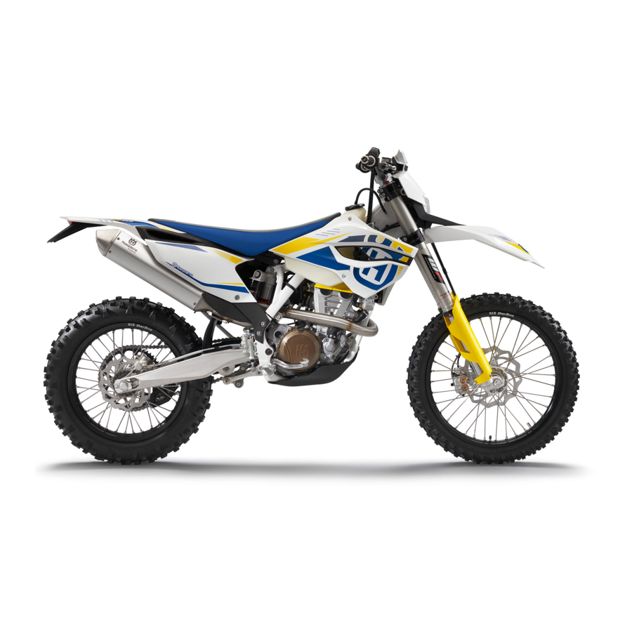
OWNER’S MANUAL 2014
FE 350 EU
FE 350 AUS
FE 350 USA
Art. no. 3402007en
Related Manuals for Husqvarna FE 350 EU
Summary of Contents for Husqvarna FE 350 EU
-
Page 1
OWNER’S MANUAL 2014 FE 350 EU FE 350 AUS FE 350 USA Art. no. 3402007en… -
Page 3
Husqvarna accepts no liability for delivery options, deviations from illustrations and descriptions or misprints and other errors. -
Page 4: Table Of Contents
Steering lock (FE 350 EU, FE 350 AUS) ….19 11.15 Adjusting the handlebar position ….. 39 6.22 Locking the steering (FE 350 EU, FE 350 AUS) ..19 SERVICE WORK ON THE CHASSIS……… 41 6.23 Unlocking the steering (FE 350 EU, 12.1…
-
Page 5
12.30 Removing the main silencer ……… 54 15.8 Changing the headlight bulb……… 83 12.31 Installing the main silencer……..54 15.9 Changing the turn signal bulb (FE 350 EU, 12.32 Changing the glass fiber yarn filling of the main FE 350 AUS) …………83 silencer …………54 15.10 Checking the headlight setting …… -
Page 6
TABLE OF CONTENTS BLINK CODE…………..100 TECHNICAL DATA …………102 23.1 Engine…………..102 23.2 Engine tightening torques……..102 23.3 Capacities…………104 23.3.1 Engine oil…………104 23.3.2 Coolant …………104 23.3.3 Fuel …………… 104 23.4 Chassis………….. 104 23.5 Electrical system ……….105 23.6 Tires………….. -
Page 7: Means Of Representation
All work marked with this symbol requires specialist knowledge and technical understanding. In the interest of your own safety, have these jobs performed by an authorized Husqvarna workshop. There, your motorcycle will be opti- mally cared for by specially trained experts using the specialist tools required.
-
Page 8: Safety Advice
Use definition — intended use (FE 350 EU, FE 350 AUS) Husqvarna sport motorcycles are designed and built to withstand the normal stresses and strains of competitive use. The motorcy- cles comply with currently valid regulations and categories of the top international motorsport organizations.
-
Page 9: Safe Operation
Wear protective clothing (helmet, boots, gloves, pants and jacket with protectors) every time you ride the vehicle. Always wear protective clothing that is in good condition and meets the legal requirements. In the interest of your own safety, Husqvarna recommends that you only operate the vehicle while wearing protective clothing. Work rules Special tools are necessary for certain tasks.
-
Page 10: Owner’s Manual
Keep the Owner’s Manual in an accessible place to enable you to refer to it as needed. If you would like to know more about the vehicle or have questions on the material you read, please contact an authorized Husqvarna dealer.
-
Page 11: Important Information
Manufacturer and implied warranty The work prescribed in the service schedule must be carried out by an authorized Husqvarna workshop only and confirmed in the cus- tomer’s service record and in the Husqvarna dealer.net; otherwise, all warranty claims will be void. No warranty claims can be consid- ered for damage resulting from manipulations and/or alterations to the vehicle.
-
Page 12: View Of Vehicle
VIEW OF VEHICLE View of vehicle, front left (example) C00576-10 Filler cap Air filter box lid Shift lever ( p. 18) Engine number ( p. 12) Side stand ( p. 18)
-
Page 13: View Of Vehicle, Rear Right (Example)
VIEW OF VEHICLE View of vehicle, rear right (example) C00575-10 Fork compression adjustment Kill switch ( p. 14) Horn button ( p. 15) Light switch ( p. 15) Turn signal switch ( p. 15) Emergency OFF switch ( p. 15) Electric starter button ( p.
-
Page 14: Serial Numbers
Chassis number The chassis number is stamped on the steering head on the right. 401945-10 Type label (FE 350 EU, FE 350 AUS) The type label is fixed to the front of the steering head. 401946-10 Key number (FE 350 EU, FE 350 AUS) The key number for the steering lock is stamped onto the key connector.
-
Page 15: Shock Absorber Part Number
SERIAL NUMBERS Shock absorber part number The shock absorber part number is stamped on the top of the shock absorber above the adjusting ring on the engine side. 0 0 1 401948-10…
-
Page 16: Controls
Throttle grip The throttle grip is fitted on the right side of the handlebar. C00531-10 Kill switch (FE 350 EU, FE 350 AUS) Kill switch is fitted on the left side of the handlebar. Possible states in basic position – the ignition circuit is closed in this position and the •…
-
Page 17: Horn Button (Fe 350 Eu, Fe 350 Aus)
Light on – Light switch is pulled out to the stop. In this position, the low beam and • tail light are switched on. B01648-10 Turn signal switch (FE 350 EU, FE 350 AUS) Turn signal switch is fitted on the left side of the handlebar. Possible states Turn signal light off –…
-
Page 18: Electric Starter Button (Fe 350 Eu, Fe 350 Usa)
Electric starter button C00592-11 6.13 Overview of indicator lamps (FE 350 EU, FE 350 AUS) Possible states High beam indicator light lights up blue – High beam is switched on. FI warning lamp (MIL) lights up/flashes orange – The OBD has detected an emission- or safety-critical fault.
-
Page 19: Closing Filler Cap
CONTROLS Warning Danger of poisoning Fuel is poisonous and a health hazard. – Fuel must not come into contact with the skin, eyes, or clothing. Do not breathe in the fuel vapors. If contact occurs with the eyes, rinse with water immediately and contact a physician. Immediately clean contaminated areas on the skin with soap and water.
-
Page 20: Shift Lever
CONTROLS 6.18 Shift lever Shift lever is mounted on the left side of the engine. 401950-10 The gear positions can be seen in the photograph. The neutral or idle position is between the first and second gears. 401950-11 6.19 Foot brake lever Foot brake lever is located in front of the right footrest.
-
Page 21: Steering Lock (Fe 350 Eu, Fe 350 Aus)
The steering lock is used to lock the steering. Steering, and therefore riding, is no longer possible. C00538-10 6.22 Locking the steering (FE 350 EU, FE 350 AUS) Note Danger of damage The parked vehicle may roll away or fall over. –…
-
Page 22: Speedometer
Message on the speedometer Possible states Battery voltage of the speedometer – Battery voltage of the speedometer is too low. Change the battery. Service – Service is due. Contact an authorized Husqvarna workshop. 401901-01 Setting the speedometer Condition The motorcycle is stationary.
-
Page 23: Setting Kilometers Or Miles
SPEEDOMETER – Wait for 5 seconds. The speedometer changes to the next menu item. The symbol flashes. Resetting the time – Press the left button. The value decreases. Advancing the time – Press the right button. The value increases. 401912-01 –…
-
Page 24: Setting The Clock
SPEEDOMETER Setting the clock Condition The motorcycle is stationary. – Press both buttons for 3–5 seconds. The Setup menu is displayed. The UNIT display flashes. – Wait for the menu of the clock to flash. – Press one of the buttons to select the 24h or 12h display of the clock. 401911-01 –…
-
Page 25: Speed, Time, And Dst Distance 1
SPEEDOMETER Speed, time, and DST distance 1 – Press one of the buttons until DST appears on the speedometer. KM/H or M/H shows the speed. shows the time. DST shows the distance since the last reset, such as between two refueling stops. Info If the value of 39999.9 is exceeded, DST is automatically reset to 0.0.
-
Page 26: Preparing For Use
When using your motorcycle, remember that others may feel disturbed by excessive noise. – Make sure that the pre-delivery inspection work has been carried out by an authorized Husqvarna workshop. You receive a delivery certificate and the service record at vehicle handover.
-
Page 27: Running-In The Engine
For this reason, it may be necessary to inspect or replace parts before the next scheduled service. – Husqvarna recommends using the specified engine oil when operating the vehicle under harsh conditions and to increase motorcycle performance. Engine oil (SAE 10W/60) ( p.
-
Page 28: Preparing For Rides On Dry Sand
PREPARING FOR USE Preparing for rides on dry sand – Fit a dust cover on the air filter. Dust protection device for air filter (77206920000) Info Observe the Husky Power fitting instructions. B00435-01 – Fit a sand cover on the air filter. Sand protection device for air filter (59006022000) Info Observe the Husky Power fitting instructions.
-
Page 29: Preparing For Rides On Wet And Muddy Surfaces
PREPARING FOR USE Preparing for rides on wet and muddy surfaces – Fit a rain cover on the air filter. Waterproofing device for air filter (77206921000) Info Observe the Husky Power fitting instructions. B00437-01 – Fit the steel sprocket. – Clean the motorcycle.
-
Page 30: Riding Instructions
RIDING INSTRUCTIONS Checks and maintenance work when preparing for use Info Before riding the vehicle, always check its condition and operating safety. The vehicle must be in perfect technical condition when used. – Check the engine oil level. ( p. 91) –…
-
Page 31: Starting Off
Do not change into a low gear at high engine speed. The engine races and the rear wheel can lock up. Info If you hear unusual noises while riding, stop immediately, switch off the engine and contact an authorized Husqvarna workshop. First gear is used for starting off or for steep inclines.
-
Page 32: Stopping, Parking
The side stand or the frame may become damaged and the motorcycle may fall over. – Brake the motorcycle. – Shift transmission to neutral. (FE 350 EU, FE 350 AUS) – Press and hold the kill switch while the engine is idling until the engine stops. (FE 350 USA) –…
-
Page 33: Refueling
– In some countries and regions, the available fuel quality and cleanliness may not be sufficient. This will result in problems with the fuel system. (Your authorized Husqvarna workshop will be glad to help.) – Only refuel with clean fuel that meets the specified standards.
-
Page 34: Service Schedule
Final check: Check the vehicle for roadworthiness and take a test ride. ○ ● ● Read out the fault memory using the Husqvarna diagnostics tool after a test ride. ○ ● ● Make the service entry in Husqvarna Dealer.net and in the service booklet.
-
Page 35: Service Work (As Additional Order)
SERVICE SCHEDULE ● Periodic interval 10.2 Service work (as additional order) Annually Every 135 operating hours/every 70 operating hours when used for motorsports Every 45 operating hours Once after 15 operating hours ● Change the front brake fluid. ● Change the rear brake fluid. ●…
-
Page 36: Tuning The Chassis
Caution Danger of accidents Disassembly of pressurized parts can lead to injury. – The shock absorber is filled with high density nitrogen. Adhere to the description provided. (Your authorized Husqvarna work- shop will be glad to help.) Info The low-speed setting can be seen during the slow to normal compression of the shock absorber.
-
Page 37: Adjusting The High-Speed Compression Damping Of The Shock Absorber
Caution Danger of accidents Disassembly of pressurized parts can lead to injury. – The shock absorber is filled with high density nitrogen. Adhere to the description provided. (Your authorized Husqvarna work- shop will be glad to help.) Info The high-speed setting can be seen during the fast compression of the shock absorber.
-
Page 38: Measuring Rear Wheel Sag Unloaded
TUNING THE CHASSIS 11.6 Measuring rear wheel sag unloaded Preparatory work – Raise the motorcycle with a lift stand. ( p. 41) Main work – Measure the distance – as vertically as possible – between the rear axle and a fixed point such as a mark on the side cover.
-
Page 39: Adjusting The Spring Preload Of The Shock Absorber
Caution Danger of accidents Disassembly of pressurized parts can lead to injury. – The shock absorber is filled with high density nitrogen. Adhere to the description provided. (Your authorized Husqvarna work- shop will be glad to help.) Info Before changing the spring preload, make a note of the present setting, e.g., by measuring the length of the spring.
-
Page 40: Checking Basic Setting Of Fork
TUNING THE CHASSIS Main work – Choose and mount a suitable spring. Guideline Spring rate Weight of rider: 65… 75 kg (143… 51 N/mm (291 lb/in) 165 lb.) Weight of rider: 75… 85 kg (165… 54 N/mm (308 lb/in) 187 lb.) Weight of rider: 85……
-
Page 41: Adjusting The Rebound Damping Of The Fork
TUNING THE CHASSIS Guideline Compression damping Comfort 15 clicks Standard 13 clicks Sport 11 clicks Info Turn clockwise to increase damping; turn counterclockwise to reduce damp- ing. 11.13 Adjusting the rebound damping of the fork Info The hydraulic rebound damping determines the fork suspension behavior. –…
-
Page 42
TUNING THE CHASSIS – Remove screws . Take off the handlebar clamps. Take off the handlebar and lay it to one side. Info Protect the motorcycle and its attachments against damage by covering them. Do not bend the cables and lines. –… -
Page 43: Service Work On The Chassis
SERVICE WORK ON THE CHASSIS 12.1 Raising the motorcycle with a lift stand Note Danger of damage The parked vehicle may roll away or fall over. – Always place the vehicle on a firm and even surface. – Raise the motorcycle at the frame underneath the engine. Lift stand (81329955000) The wheels must no longer touch the ground.
-
Page 44: Loosening The Fork Protector
SERVICE WORK ON THE CHASSIS Warning Danger of accidents Reduced braking efficiency due to oil or grease on the brake discs. – Always keep the brake discs free of oil and grease, and clean them with brake cleaner when necessary. – Clean and oil the dust boots and inner fork tube of both fork legs.
-
Page 45: Installing The Fork Legs
SERVICE WORK ON THE CHASSIS – Release screws . Take out the left fork leg. – Release screws . Take out the right fork leg. C00579-10 12.8 Installing the fork legs Main work – Position the fork legs. Info The compression damping is located in the left fork leg COMP (white adjust- ing screw).
-
Page 46: Installing The Fork Protector
SERVICE WORK ON THE CHASSIS Main work – Remove screws on the left fork leg. Remove the fork protector upwards. – Remove the screws on the right fork leg. Remove the fork protector upwards. C00565-10 12.10 Installing the fork protector Main work –…
-
Page 47: Installing The Lower Triple Clamp
SERVICE WORK ON THE CHASSIS – Remove O-ring . Remove protective ring – Take off the lower triple clamp with the steering stem. – Remove the upper steering head bearing. C00567-11 12.12 Installing the lower triple clamp Main work – Clean the bearing and sealing elements, check for damage, and grease.
-
Page 48: Checking The Steering Head Bearing Play
Danger of accidents Unstable vehicle handling from incorrect steering head bearing play. – Adjust the steering head bearing play without delay. (Your authorized Husqvarna workshop will be glad to help.) Info If the bike is ridden with play in the steering head bearing, the bearing and the bearing seats in the frame can become damaged…
-
Page 49: Adjusting The Play Of The Steering Head Bearing
SERVICE WORK ON THE CHASSIS Preparatory work – Raise the motorcycle with a lift stand. ( p. 41) Main work – Move the handlebar to the straight-ahead position. Move the fork legs to and fro in the direction of travel. No play should be noticeable in the steering head bearing.
-
Page 50: Removing The Front Fender
SERVICE WORK ON THE CHASSIS 12.16 Removing the front fender Preparatory work – Switch off all power consumers and switch off the engine. – Remove the headlight mask with the headlight. ( p. 82) Main work – Disconnect plug-in connectors of the turn signals.
-
Page 51: Removing The Shock Absorber
SERVICE WORK ON THE CHASSIS 12.18 Removing the shock absorber Preparatory work – Raise the motorcycle with a lift stand. ( p. 41) – Remove the right side cover. ( p. 55) – Remove the main silencer. ( p. 54) –…
-
Page 52: Removing The Air Filter Box Lid
SERVICE WORK ON THE CHASSIS 12.22 Removing the air filter box lid – Release catch , pull off the air filter box lid sideways in areas remove toward the rear. B01817-10 12.23 Installing the air filter box lid – Position the air filter box lid and tab .
-
Page 53: Cleaning The Air Filter And Air Filter Box
SERVICE WORK ON THE CHASSIS – Insert both parts together, position them, and fasten them using air filter holder area The arrow of marking UP faces up. Info If the air filter is not correctly mounted, dust and dirt can enter the engine and cause damage.
-
Page 54: Removing The Manifold
SERVICE WORK ON THE CHASSIS 12.28 Removing the manifold Preparatory work – Remove the seat. ( p. 49) – Remove the right side cover. ( p. 55) – Remove the main silencer. ( p. 54) – Raise the motorcycle with a lift stand. ( p.
-
Page 55: Installing The Manifold
SERVICE WORK ON THE CHASSIS – Remove springs 309349-10 – Remove screw and take off the manifold. 309350-10 12.29 Installing the manifold Main work – Position the manifold and mount springs Spring hooks (50305017000) 309349-11 – Mount and tighten screw Guideline Remaining screws, chassis 25 Nm (18.4 lbf ft)
-
Page 56: Removing The Main Silencer
SERVICE WORK ON THE CHASSIS – Position the angle lever and linkage lever. – Mount and tighten fitting Guideline Nut, linkage lever on angle lever M14x1.5 80 Nm (59 lbf ft) – Mount and tighten screw Guideline Screw, bottom shock 60 Nm Loctite ®…
-
Page 57: Removing The Right Side Cover
Remove the right side cover. ( p. 55) – Remove the main silencer. ( p. 54) Main work (FE 350 EU, FE 350 AUS) – Remove all screws on the main silencer. – Take off silencer cap and O-ring –…
-
Page 58: Installing The Right Side Cover
SERVICE WORK ON THE CHASSIS 12.34 Installing the right side cover – Position the side cover and engage in area – Mount and tighten screw Guideline Remaining screws, chassis 10 Nm (7.4 lbf ft) B01813-10 12.35 Removing the fuel tank Danger Fire hazard Fuel is highly flammable.
-
Page 59: Installing The Fuel Tank
SERVICE WORK ON THE CHASSIS – Remove screw with the rubber bushing. B01809-11 – Pull both spoilers off of the sides of the radiator bracket and lift off the fuel tank. B01810-01 12.36 Installing the fuel tank Danger Fire hazard Fuel is highly flammable. –…
-
Page 60: Checking For Chain Dirt Accumulation
SERVICE WORK ON THE CHASSIS – Attach connector of the fuel pump. – Remove the wash cap set. – Thoroughly clean the plug-in connection of the fuel line using compressed air. Info Never let dirt enter the fuel line. Dirt in the fuel line clogs the injection valve. –…
-
Page 61: Checking The Chain Tension
SERVICE WORK ON THE CHASSIS 12.39 Checking the chain tension Warning Danger of accidents Danger caused by incorrect chain tension. – If the chain is too taut, the components of the secondary power transmission (chain, engine sprocket, rear sprocket, bearings in the transmission and in the rear wheel) will be under additional load. In addition to premature wear, this can cause the chain or the countershaft of the transmission to break in extreme cases.
-
Page 62: Checking The Chain, Rear Sprocket, Engine Sprocket And Chain Guide
SERVICE WORK ON THE CHASSIS Finishing work – Remove the motorcycle from the lift stand. ( p. 41) 12.41 Checking the chain, rear sprocket, engine sprocket and chain guide Preparatory work – Raise the motorcycle with a lift stand. ( p.
-
Page 63: Checking The Frame
SERVICE WORK ON THE CHASSIS – Check the chain sliding piece for wear. » If the bottom edge of the chain bolt is in line with or below the chain sliding piece: – Change the chain sliding piece. – Check that the chain sliding piece is firmly seated. »…
-
Page 64: Checking The Swingarm
If the swingarm shows signs of damage, cracking, or deformation: – Change the swingarm. Info A damaged swingarm must always be changed. Repair of the swingarm is not authorized by Husqvarna. 401520-01 12.44 Checking the routing of the throttle cable Preparatory work –…
-
Page 65: Additionally Securing The Rubber Grip
SERVICE WORK ON THE CHASSIS 12.46 Additionally securing the rubber grip Preparatory work – Check the rubber grip. ( p. 62) Main work – Secure the rubber grip at two points using the securing wire. Securing wire (54812016000) Wire twister forceps (U6907854) The twisted wire ends face away from the hands and are bent toward the rubber grip.
-
Page 66: Removing The Engine Guard
SERVICE WORK ON THE CHASSIS – Move the clutch fluid reservoir mounted on the handlebar to a horizontal position. – Remove screws – Remove cover with membrane B01538-10 – Fill bleeding syringe with the appropriate hydraulic fluid. Bleed syringe (50329050000) Brake fluid DOT 4 / DOT 5.1 ( p.
-
Page 67: Brake System
Adjust the basic position of the hand brake lever. ( p. 65) B01637-10 13.2 Adjusting free travel of hand brake lever (FE 350 EU, FE 350 AUS) – Check the free travel of the hand brake lever. ( p. 65) –…
-
Page 68: Checking The Brake Discs
Warning Danger of accidents Reduced braking efficiency due to old brake fluid. – Change the brake fluid of the front and rear brake according to the service schedule. (Your authorized Husqvarna workshop will be glad to help.) – Move the brake fluid reservoir mounted on the handlebar to a horizontal position.
-
Page 69: Checking The Front Brake Linings
Warning Danger of accidents Reduced braking efficiency due to old brake fluid. – Change the brake fluid of the front and rear brake according to the service schedule. (Your authorized Husqvarna workshop will be glad to help.) Warning Environmental hazard Hazardous substances cause environmental damage.
-
Page 70: Changing The Front Brake Linings
Warning Danger of accidents Reduced braking efficiency due to old brake fluid. – Change the brake fluid of the front and rear brake according to the service schedule. (Your authorized Husqvarna workshop will be glad to help.) Warning Danger of accidents Reduced braking efficiency due to oil or grease on the brake discs.
-
Page 71: Checking The Free Travel Of Foot Brake Lever
BRAKE SYSTEM – Check that leaf spring in the brake caliper and sliding plate in the brake caliper support are seated correctly. 100397-01 – Insert the new brake linings, insert the pin, and mount the cotter pin. Info Always change the brake linings in pairs. –…
-
Page 72: Checking The Rear Brake Fluid Level
Warning Danger of accidents Reduced braking efficiency due to old brake fluid. – Change the brake fluid of the front and rear brake according to the service schedule. (Your authorized Husqvarna workshop will be glad to help.) – Stand the vehicle upright.
-
Page 73: Checking The Rear Brake Linings
Warning Danger of accidents Reduced braking efficiency due to old brake fluid. – Change the brake fluid of the front and rear brake according to the service schedule. (Your authorized Husqvarna workshop will be glad to help.) Warning Environmental hazard Hazardous substances cause environmental damage.
-
Page 74: Changing The Rear Brake Linings
Warning Danger of accidents Reduced braking efficiency due to old brake fluid. – Change the brake fluid of the front and rear brake according to the service schedule. (Your authorized Husqvarna workshop will be glad to help.) Warning Danger of accidents Reduced braking efficiency due to oil or grease on the brake discs.
-
Page 75
BRAKE SYSTEM – Check that leaf spring in the brake caliper and sliding plate in the brake caliper support are seated properly. L00194-10 – Insert the new brake linings, insert the pin, and mount the cotter pin. Info Always change the brake linings in pairs. –… -
Page 76: Wheels, Tires
WHEELS, TIRES 14.1 Removing the front wheel Preparatory work – Raise the motorcycle with a lift stand. ( p. 41) Main work – Press the brake caliper onto the brake disc by hand in order to push back the brake pistons.
-
Page 77: Removing The Rear Wheel
WHEELS, TIRES – Lift the front wheel into the fork, position it, and insert the wheel spindle. The brake linings are positioned. – Mount and tighten screw Guideline Screw, front wheel spindle M24x1.5 45 Nm (33.2 lbf ft) – Activate the hand brake lever multiple times until the brake linings are in contact with the brake disc.
-
Page 78: Installing The Rear Wheel
Checking the tire condition Info Only mount tires approved and/or recommended by Husqvarna. Other tires could have a negative effect on handling characteristics. The type, condition, and air pressure of the tires all have a significant impact on the handling characteristics of the motorcycle.
-
Page 79: Checking The Tire Air Pressure
Danger of accidents Instable handling due to incorrect spoke tension. – Ensure that the spoke tension is correct. (Your authorized Husqvarna workshop will be glad to help.) Info A loose spoke can cause wheel imbalance, which leads to more loose spokes in a short time.
-
Page 80
WHEELS, TIRES – Tap each spoke with a screwdriver. Info The sound frequency depends on the length and thickness of the spoke. If there are different sound frequencies in spokes with the same length and thickness, this indicates different spoke tensions. You should hear a high note. -
Page 81: Electrical System
ELECTRICAL SYSTEM 15.1 Removing the battery Warning Risk of injury Battery acid and battery gases cause serious chemical burns. – Keep batteries out of the reach of children. – Wear suitable protective clothing and goggles. – Avoid contact with battery acid and battery gases. –…
-
Page 82: Charging The Battery
– Do not dispose of batteries with the household waste. Dispose of a defective battery in an environmentally friendly manner. Give it to your Husqvarna dealer or to a disposal center for used batteries. Warning Environmental hazard Hazardous substances cause environmental damage.
-
Page 83: Changing The Main Fuse
ELECTRICAL SYSTEM 15.4 Changing the main fuse Warning Fire hazard The electrical system can be overloaded if the wrong fuses are used. – Use only fuses with the prescribed amperage. Never by-pass or repair fuses. Info The main fuse protects all power consumers of the vehicle. It is located in the starter relay housing under the air filter box lid. Preparatory work –…
-
Page 84: Removing The Headlight Mask With The Headlight
ELECTRICAL SYSTEM – Remove the defective fuse. Guideline Fuse 1 — 10 A — EFI control unit Fuse 2 — 10 A — fuel pump Fuse 3 — 10 A — high beam, low beam, parking light, tail light, license plate lamp Fuse 4 — 10 A — horn, brake light, turn signal, radiator fan (optional) Fuses res — 10 A — spare fuses B01642-10…
-
Page 85: Changing The Headlight Bulb
– Check the headlight setting. ( p. 84) 15.9 Changing the turn signal bulb (FE 350 EU, FE 350 AUS) Note Damage to reflector Reduced brightness. – Grease on the lamp will evaporate due to the heat and be deposited on the reflector. Clean the lamp and keep it free of grease…
-
Page 86: Checking The Headlight Setting
ELECTRICAL SYSTEM Main work – Remove the screw on the rear of the turn signal housing. – Carefully remove diffuser – Lightly squeeze orange cap in the area of the holding lugs and take it off. – Press the turn signal bulb lightly into the socket, turn it counterclockwise by about 30°, and take it out of the socket.
-
Page 87: Changing The Speedometer Battery
ELECTRICAL SYSTEM 15.12 Changing the speedometer battery Preparatory work – Switch off all power consumers and switch off the engine. – Remove the headlight mask with the headlight. ( p. 82) Main work – Remove screws – Pull the speedometer upward out of the holder. B01786-10 –…
-
Page 88: Cooling System
COOLING SYSTEM 16.1 Cooling system The water pump in the engine forces the coolant to flow. The pressure resulting from the warming of the cooling system is regulated by a valve in radiator cap . The specified coolant temperature is therefore permissible without the danger of malfunctions.
-
Page 89: Checking The Coolant Level
COOLING SYSTEM 16.3 Checking the coolant level Warning Danger of scalding During motorcycle operation, the coolant gets very hot and is under pressure. – Do not remove the radiator cap, radiator hoses or other cooling system components when the engine is hot. Allow the engine and cooling system to cool down.
-
Page 90: Refilling Coolant
COOLING SYSTEM 16.5 Refilling coolant Warning Danger of poisoning Coolant is poisonous and a health hazard. – Coolant must not come into contact with the skin, eyes, or clothing. If contact occurs with the eyes, rinse with water imme- diately and contact a physician. Immediately clean contaminated areas on the skin with soap and water. If coolant is swal- lowed, contact a physician immediately.
-
Page 91: Tuning The Engine
TUNING THE ENGINE 17.1 Checking the play in the throttle cable – Check the throttle grip for smooth operation. – Move the handlebar to the straight-ahead position. Move the throttle grip back and forth slightly to ascertain play in the throttle cable. Play in throttle cable 3……
-
Page 92: Adjusting The Idle Speed
TUNING THE ENGINE 17.3 Adjusting the idle speed – Run the engine warm and push the idle speed adjusting screw all the way in. – Set the desired idle speed by turning the idle speed adjusting screw. Guideline Idle speed 1,950……
-
Page 93: Service Work On The Engine
SERVICE WORK ON THE ENGINE 18.1 Changing the fuel screen Danger Fire hazard Fuel is highly flammable. – Never refuel the vehicle near open flames or burning cigarettes, and always switch off the engine first. Be careful that no fuel is spilt, especially on hot vehicle components. Clean up spilt fuel immediately. –…
-
Page 94: Changing The Engine Oil And Oil Filter, Cleaning The Oil Screen
SERVICE WORK ON THE ENGINE The engine oil is at a level between the lower edge and the upper edge of the level viewer. » If the engine oil is not up to the lower edge of the level viewer: –…
-
Page 95
SERVICE WORK ON THE ENGINE – Mount and tighten screw plug with the O-ring. Guideline Screw plug, oil screen M20x1.5 15 Nm (11.1 lbf ft) – Mount and tighten the oil drain plug with the magnet and a new seal ring. Guideline Oil drain plug with magnet M12x1.5… -
Page 96: Adding Engine Oil
SERVICE WORK ON THE ENGINE – Start the engine and check that it is oil-tight. Finishing work – Check the engine oil level. ( p. 91) – Install the engine guard. ( p. 64) 18.4 Adding engine oil Info Too little engine oil or poor-quality engine oil results in premature wear to the engine. Main work –…
-
Page 97: Cleaning, Care
Treat bare metal parts (except for brake discs and exhaust system) with anti-corrosion materials. – Treat all plastic parts and powder-coated parts with a mild cleaning and care prod- uct. (FE 350 EU, FE 350 AUS) – Lubricate the steering lock. 19.2 Checks and maintenance steps for winter operation Info If the motorcycle is used in the winter, salt can be expected on the roads.
-
Page 98
CLEANING, CARE – Clean the motorcycle. ( p. 95) – Clean the brake system. Info After EVERY trip on salted roads, thoroughly wash the brake calipers and brake linings with cold water and dry carefully. This should be done after the parts are cooled down and while they are installed. -
Page 99: Storage
– Store the vehicle in a dry location that is not subject to large fluctuations in tempera- ture. Info Husqvarna recommends raising the motorcycle. – Raise the motorcycle with a lift stand. ( p. 41) – Cover the motorcycle with a porous sheet or blanket. Do not use non-porous materi- als since they prevent humidity from escaping, thus causing corrosion.
-
Page 100: Troubleshooting
– Check the electrical system. switch defective – Defect in fuel injection system Read out the fault memory using the Husqvarna diagnostics tool. – Engine does not speed up Defect in fuel injection system Read out the fault memory using the Husqvarna diagnostics tool.
-
Page 101
See blink code – Check the cabling for damage and the electrical plug-in connections for corrosion and damage. – Read out the fault memory using the Husqvarna diagnostics tool. – High oil consumption Engine vent hose bent Route the vent hose without bends or replace it if necessary. -
Page 102: Blink Code
Blink code FI warning lamp (MIL) 17 FI warning lamp (MIL) flashes 1x long, 7x short Error level condition FE 350 EU Lambda sensor cylinder 1, sensor 1 — circuit fault Blink code FI warning lamp (MIL) 33 FI warning lamp (MIL) flashes 3x long, 3x short…
-
Page 103
(MIL) 45 FI warning lamp (MIL) flashes 4x long, 5x short Error level condition FE 350 EU Lambda sensor heater cylinder 1, sensor 1 — short circuit to ground or open circuit FE 350 EU Lambda sensor heater cylinder 1, sensor 1 — input signal too high… -
Page 104: Technical Data
TECHNICAL DATA 23.1 Engine Design 1-cylinder 4-stroke engine, water-cooled Displacement 349.7 cm³ (21.34 cu in) Stroke 57.5 mm (2.264 in) Bore 88 mm (3.46 in) Compression ratio 12.3:1 Idle speed 1,950… 2,050 rpm Control DOHC, four valves controlled via cam lever, drive via timing chain Valve diameter, intake 36.3 mm (1.429 in) Valve diameter, exhaust…
-
Page 105
TECHNICAL DATA ® Screw, oil pump cover 6 Nm (4.4 lbf ft) Loctite 243™ ® Screw, stator 6 Nm (4.4 lbf ft) Loctite 243™ Nut, cylinder head 10 Nm (7.4 lbf ft) Lubricated with engine oil ® Nut, water-pump wheel 6 Nm (4.4 lbf ft) Loctite 243™… -
Page 106: Capacities
Tire air pressure off road Front 1.0 bar (15 psi) Rear 1.0 bar (15 psi) Road tire pressure (FE 350 EU, FE 350 AUS) Front 1.5 bar (22 psi) Rear 1.5 bar (22 psi) Final drive (FE 350 EU, FE 350 AUS)
-
Page 107: Electrical System
W5W / socket W2.1×9.5d 12 V Indicator lamps W2.3W / socket W2x4.6d 12 V 2.3 W Turn signal (FE 350 EU, FE 350 AUS) R10W / socket BA15s 12 V 10 W Brake/tail light License plate lamp (FE 350 EU, W5W / socket W2.1×9.5d…
-
Page 108: Shock Absorber
TECHNICAL DATA 23.8 Shock absorber Shock absorber part number 18.15.7N.67 WP Suspension 5018 BAVP DCC Shock absorber Compression damping, low-speed Comfort 20 clicks Standard 18 clicks Sport 16 clicks Compression damping, high-speed Comfort 2.5 turns Standard 2 turns Sport 1.5 turns Rebound damping Comfort 20 clicks…
-
Page 109
TECHNICAL DATA – Screw, bottom triple clamp 15 Nm (11.1 lbf ft) – Screw, chain sliding piece 15 Nm (11.1 lbf ft) – Screw, engine brace 33 Nm (24.3 lbf ft) – Screw, fork stub 15 Nm (11.1 lbf ft) ®… -
Page 110: Substances
SUBSTANCES Brake fluid DOT 4 / DOT 5.1 Standard/classification – Guideline – Use only brake fluid that complies with the specified standard (see specifications on the container) and that possesses the corre- sponding properties. Coolant Guideline – Use only suitable coolant (even in countries with high temperatures). Using inferior antifreeze can result in corrosion and foaming. –…
-
Page 111
SUBSTANCES Super unleaded (ROZ 95/RON 95/PON 91) Standard/classification – DIN EN 228 (ROZ 95/RON 95/PON 91) Guideline – Only use unleaded super fuel that matches or is equivalent to the specified fuel grade. – Fuel with an ethanol content of up to 10 % (E10 fuel) is safe to use. Info Do not use fuel containing methanol (e. -
Page 112: Auxiliary Substances
AUXILIARY SUBSTANCES High viscosity grease Recommended supplier ® – LGHB 2 Rubber grip adhesive (00062030051) Recommended supplier KTM-Sportmotorcycle AG – GRIP GLUE…
-
Page 113: Standards
STANDARDS JASO T903 MA Different technical development directions required a new specification for 4-stroke motorcycles – the JASO T903 MA Standard. Earlier, engine oils from the automobile industry were used for 4-stroke motorcycles because there was no separate motorcycle specification. Whereas long service intervals are demanded for automobile engines, high performance at high engine speeds are in the foreground for motorcycle engines.
-
Page 114: Index
INDEX INDEX fluid, changing ……63 Clutch lever ……. . 14 Accessories .
-
Page 115
INDEX Foot brake lever ……18 basic position, adjusting ….. . . 69 Light switch . -
Page 116
INDEX Throttle grip ……. . 14 Safe operation ……. 7 Tire air pressure checking . -
Page 117
*3402007en* 3402007en 09/2013 Husqvarna Motorcycles GmbH 5230 Mattighofen Stallhofnerstraße 3 Photo: Austria Mitterbauer/Husqvarna Motorcycles GmbH…
Не можете найти ответ на свой вопрос в руководстве? Вы можете найти ответ на свой вопрос ниже, в разделе часто задаваемых вопросов о Husqvarna FE 350 (2020).
Как перевести мили в километры?
В чем разница между топливом E10 и E5?
Какова рекомендуемая частота замены масляного фильтра в двигателе Husqvarna?
Как часто следует менять масло в двигателе Husqvarna?
Как удалить ржавчину с устройства Husqvarna Мотоцикл?
Инструкция Husqvarna FE 350 (2020) доступно в русский?
Не нашли свой вопрос? Задайте свой вопрос здесь
Motorcycle Manuals
Apparel & Technical Accessories Manuals
Here is your personal document
If you prefer a printed document to thumb through, or you would like to search for an older document, these are available in the Print on Demand portal.
In the portal, you can find owner’s and repair manuals for a wide variety of models.
You can choose between PDF downloads and printed copies.