-
Contents
-
Table of Contents
-
Troubleshooting
-
Bookmarks
Quick Links
INSTRUCTION MANUAL
VHF TRANSCEIVER
i2200H
This device complies with Part 15 of the FCC rules. Operation is sub-
ject to the following two conditions: (1) This device may not cause
harmful interference, and (2) this device must accept any interference
received, including interference that may cause undesired operation.
Related Manuals for Icom IC-2200H
Summary of Contents for Icom IC-2200H
-
Page 1
INSTRUCTION MANUAL VHF TRANSCEIVER i2200H This device complies with Part 15 of the FCC rules. Operation is sub- ject to the following two conditions: (1) This device may not cause harmful interference, and (2) this device must accept any interference received, including interference that may cause undesired operation. -
Page 3: Foreword
We want to take a couple of moments of your time to thank the IC-2200H. you for making your IC-2200H your radio of choice, and hope you agree with Icom’s philosophy of “technology first.” Many hours of research and development went into the design of EXPLICIT DEFINITIONS your IC-2200H.
-
Page 4: Precaution
NEVER expose the transceiver to rain, snow or any liquids. Icom microphones only (supplied or optional). Other man- The transceiver may be damaged. ufacturer’s microphones have different pin assignments and may damage the transceiver if attached.
-
Page 5: Supplied Accessories And Options
SUPPLIED ACCESSORIES AND OPTIONS I Supplied Accessories I Options q Microphone (HM-133V)* ……1 UT-108 DTMF DECODER UNIT w Fuse (20 A) .
-
Page 6: Table Of Contents
TABLE OF CONTENTS I Transmitting …………….. 15 FOREWORD ………………. i I Selecting output power …………..16 IMPORTANT ……………….. i I One-touch PTT function …………… 16 EXPLICIT DEFINITIONS …………….. i PRECAUTION ………………ii 4 REPEATER OPERATION …………17–23 I Accessing a repeater …………..17 SUPPLIED ACCESSORIES AND OPTIONS ………
-
Page 7
I Weather channel operation …………83 8 PRIORITY WATCH …………..43–44 I Priority watch types …………..43 I Microphone keys …………….84 I Priority watch operation …………… 44 I Partial reset ……………… 85 I All reset ………………85 9 DTMF MEMORY ENCODER …………. 45–47 I Programming a DTMF code ………… -
Page 8: Quick Reference Guide
Flat washer Mounting bracket AVOID placing the transceiver in direct sunlight. When using self-tapping screws Mounting Spring washer IMPORTANT! Detailed installation notes for Icom mobile transceivers to be fitted into vehicles are available. Contact your Icom dealer or distributor.
-
Page 9: Battery Connection
• CONNECTING TO A DC POWER SUPPLY • See p. 90 for fuse replacement. • CONNECTING TO A DC POWER SOURCE • See p. 90 for fuse replacement. Grommet IC-2200H IC-2200H DC power − ⊕ black + red supply 13.8 V…
-
Page 10: Antenna Installation
Check with your local dealer for more information and recommendations. D Connecting a microphone Connect a microphone to the eight-pin modular socket on the front panel of the transceiver. *HM-133V; A different microphone may be supplied with some versions of the IC-2200H. to antenna…
-
Page 11: I Your First Contact
2. Tune the desired frequency [DIAL] will allow you to dial in the frequency you want to op- Now that you have your IC-2200H installed in your car or erate. Pages 9 and 11 will instruct you on how to set the tun- shack, you are probably excited to get on the air.
-
Page 12: I Repeater Operation
QUICK REFERENCE GUIDE I Repeater operation 1. Setting duplex Using the HM-133V Plus or minus duplex selection and the repeater tone setting Push [LOW ] for 1 sec. once or twice to select minus can be made easily via HM-133V. duplex or plus duplex.
-
Page 13: I Programming Memory
QUICK REFERENCE GUIDE I Programming memory channels The IC-2200H has a total of 207 memory channels (including Using the HM-133V 6 scan edges and 1 call channel) for storing often used oper- q In VFO mode, set the desired operating frequency, includ- ating frequency, repeater settings, etc.
-
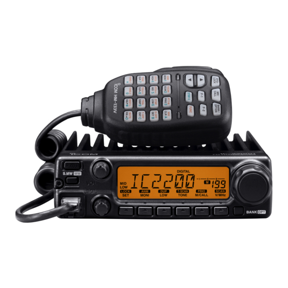
Page 14: Panel Description
PANEL DESCRIPTION I Front panel Function display (p. 3) S.MW BANK q POWER KEY [PWR] e MICROPHONE CONNECTOR Turns power ON and OFF when pushed for 1 sec. Connects the supplied microphone. w MEMORY WRITE KEY [S.MW r VOLUME CONTROL [VOL] (p. 13) ] (p.
-
Page 15
PANEL DESCRIPTION y SET•LOCK KEY [SET !1 VFO/MHz TUNING•SCAN KEY [V/MHz LOCK SCAN ➥ Enters set mode when pushed. (p. 74) ➥ Selects and toggles VFO mode and 1 MHz (or 10 MHz ➥ Keys the lock function ON and OFF when pushed for for some versions) tuning when pushed. -
Page 16: I Function Display
PANEL DESCRIPTION I Function display DIGITAL PRIO AO BUSY MUTE T — SCAN LOCK PRIO SCAN S ET MONI TONE M/CALL V/MHz q FREQUENCY READOUT e AUDIO MUTE INDICATOR (p. 14) Shows the operating frequency, channel names, set mode Appears when the audio mute function is activated via mi- contents, etc.
-
Page 17
PANEL DESCRIPTION y KEY INDICATORS !4 DIGITAL INDICATOR (p. 61) Indicate the function(s) of the front panel keys directly Appears when digital mode is selected. below the function display. !5 LOCK INDICATOR (p. 12) u SKIP INDICATOR (p. 41) Appears when the lock function is activated. Appears when the selected memory channel is specified !6 TONE INDICATORS as a skip channel. -
Page 18: I Rear Panel
PANEL DESCRIPTION I Rear panel q SPEAKER JACK [SP] e POWER RECEPTACLE [DC13.8V] Accepts an 8 Ω speaker. Accepts 13.8 V DC ±15% with the supplied DC power • Audio output power is more than 2.4 W. cable.51 w DATA JACK [DATA] NOTE: DO NOT use a cigarette lighter socket as a Connects to a PC or GPS receiver via an RS-232C cable power source when operating in a vehicle.
-
Page 19: I Microphone (Hm-133V)
PANEL DESCRIPTION I Microphone (HM-133V*) e UP/DOWN KEYS [Y]/[Z] ➥ Push either key to change operating frequency, mem- ory channel, set mode setting, etc. (pgs. 10, 24) ➥ Push either key for 1 sec. to start scanning. (p. 38) r ACTIVITY INDICATOR ➥…
-
Page 20: I Microphone Keypad
PANEL DESCRIPTION I Microphone keypad FUNCTION SECONDARY FUNCTION ( +key) OTHER FUNCTIONS Switches between opening and closing the In memory mode switches the channel names squelch. (p. 13) or number indication ON and OFF. (p. 30) Starts and stops scanning. (p.
-
Page 21
PANEL DESCRIPTION FUNCTION SECONDARY FUNCTION ( +key) OTHER FUNCTIONS ➥ Cancels frequency entry. ➥ Selects a memory channel for program- (p. 10) ➥ Cancels the scan or priority watch. ming. (p. 26) ➥ Advances the memory channel number (pgs. 38, 44) ➥… -
Page 22: Setting A Frequency
SETTING A FREQUENCY I Preparation I Using the tuning dial D Turning power ON/OFF qRotate [DIAL] to set the frequency. ➥ Push [PWR] for 1 sec. to DIGITAL PRIO AO BUSY MUTE turn power ON and OFF. LOCK T-SCAN PRIO SCAN S ET MONI…
-
Page 23: I Using The Keypad
SETTING A FREQUENCY I Using the keypad I Using the [Y]/[Z] keys ➥ Push [Y Y ] or [Z Z ] to select the desired frequency. The frequency can be directly set via numeral keys on the mi- crophone. • Pushing [Y Y ]/[Z Z ] for 1 sec. activates a scan. If scan starts, push [Y Y ]/[Z Z ] again or push [ A(MW)] to z Push [VFO/LOCK] to VFO mode, if necessary.
-
Page 24: I Tuning Step Selection
SETTING A FREQUENCY I Tuning step selection SET MODE USING Tuning steps are the minimum frequency change increments z Push [VFO/LOCK] to select VFO mode, if when you rotate [DIAL] or push [Y Y ]/[Z Z ] on the microphone. VFO/LOCK necessary.
-
Page 25: I Lock Functions
SETTING A FREQUENCY I Lock functions D Microphone keypad lock To prevent accidental channel changes and unnecessary function access, use the lock function. The transceiver has 2 This function locks the microphone keypad. different lock functions. ➥ Push [FUNC] then [ #(16KEY-L)] to D Frequency lock 16KEY-L…
-
Page 26: Basic Operation
BASIC OPERATION I Receiving I Monitor function q Push [PWR] for 1 sec. to turn power ON. This function is used to listen to weak signals without disturb- w Set the audio level. ing the squelch setting or to open the squelch manually even ➥…
-
Page 27: I Audio Mute Function
BASIC OPERATION I Audio mute function I Squelch attenuator This function temporarily mutes the audio without disturbing The transceiver has an RF attenuator related to the squelch the volume setting. level setting. Approx. 10 dB attenuation is obtained at maxi- mum setting.
-
Page 28: I S-Meter Squelch
Rotate [DIAL] to set the S-meter level or OFF. DIGITAL PRIO AO BUSY DIGITAL PRIO AO BUSY MUTE MUTE IMPORTANT! (for 65 W transmission): The IC-2200H is equipped with current detector circuit to LOCK T-SCAN PRIO SCAN LOCK T-SCAN…
-
Page 29: I Selecting Output Power
BASIC OPERATION I Selecting output power I One-touch PTT function The transceiver has 4* output power levels to suit your oper- The PTT switch can be operated as a one-touch PTT switch ating requirements. Low output powers during short-distance (each push switches between transmit/receive). Using this communications may reduce the possibility of interference to function you can transmit without pushing and holding the other stations and will reduce current consumption.
-
Page 30: Repeater Operation
REPEATER OPERATION I Accessing a repeater q Set the receive frequency (repeater output frequency). r Push and hold [PTT] to transmit. (pgs. 9, 10) • The displayed frequency automatically changes to the transmit frequency (repeater input frequency). Push [LOW ] for 1 sec., once or twice, to select •…
-
Page 31
REPEATER OPERATION z Set the receive frequency (repeater output fre- m Push [ 9(TSQL)] to return to simplex oper- SIMP DUP– SIMP quency). (pgs. 9, 10) ation. x Push [ • “+” or “–” indicator disappears. – 7(TONE)] to select minus duplex; , To turn OFF the subaudible tone encoder, push S )] to select plus duplex. -
Page 32: I Subaudible Tones
REPEATER OPERATION I Subaudible tones z Set the mode/channel you wish to set the sub- SET MODE USING audible tones to, such as VFO mode or mem- (Encoder function) ory/call channel. • The subaudible tone frequency is independently pro- D Subaudible tones grammed into each mode or channel.
-
Page 33
REPEATER OPERATION D DTMF tones D 1750 Hz tone ➥ Push [DTMF-S], then push the keys of the de- The microphone has 1750 Hz tone capability, used for ring DTMF-S sired DTMF digits. tone when calling, etc. • The function indicator lights green. z Push [FUNC]. -
Page 34: I Offset Frequency
REPEATER OPERATION I Offset frequency I Repeater lockout SET MODE USING INITIAL SET MODE USING When communicating thorough a repeater, the transmit fre- quency is shifted from the receive frequency by an amount This function helps prevent interference to other stations by determined by the offset frequency.
-
Page 35: I Reversed Duplex Mode
REPEATER OPERATION I Reversed duplex mode SET MODE USING z Push [ When the reversed duplex mode is selected, the receive fre- B(D-OFF)] to enter set mode. x Push [ quency shifts. B(D-OFF)] or [ C(T-OFF)] until (Transmit frequency shifts in normal duplex mode.) Each receive and transmit frequency is shown in the table “REV”…
-
Page 36: I Auto Repeater
REPEATER OPERATION I Auto repeater (U.S.A. version only) INITIAL SET MODE USING r Rotate [DIAL] to turn the auto repeater function to “R1,” The USA version automatically activate the repeater settings when the operating “R2” or OFF. (DUP– or DUP+ and tone encoder ON/OFF) frequency falls within the general repeater output frequency DIGITAL PRIO AO BUSY DIGITAL PRIO AO BUSY…
-
Page 37: Memory Operation
MEMORY OPERATION I General description D Using the [Y]/[Z] keys The transceiver has 207 memory channels including 6 scan edge memory channels (3 pairs), and 1 call channel. Each of z Push [MR/CALL] to select memory mode. these channels can be individually programmed with operat- MR/CALL x Push [Y Y ] or [Z Z ] to select and set the desired ing frequency (pgs.
-
Page 38: I Programming A Memory Channel
MEMORY OPERATION I Programming a memory channel e Rotate [DIAL] to select the memory channel to be pro- VFO settings, including the set mode contents such as sub- audible tone frequency, etc., can be programmed into a mem- grammed. ory channel. •…
-
Page 39: Programming A Memory Channel Via The Microphone
MEMORY OPERATION D Programming a memory channel via the microphone The microphone can also be used to program mem- ory channels. z Set the desired frequency in VFO mode. v Push [FUNC] then [ A(MW)] for 1 sec. to program. ➥…
-
Page 40: I Transferring Memory Contents
MEMORY OPERATION I Transferring memory contents This function transfers a memory channel’s contents to VFO (or another memory/call channel). This is useful when search- ing for signals around a memory channel frequency and for recalling the offset frequency, subaudible tone frequency etc. D Memory/call➪VFO z Select the memory/call channel to be MR/CALL…
-
Page 41
MEMORY OPERATION z Select the memory/call channel to be trans- D Memory/call➪call/memory MR/CALL ferred. q Select the memory/call channel to be transferred. ➥ Push [MR/CALL] to select memory mode, ➥ Push [M/CALL PRIO ] to select memory mode, then ro- then select the desired memory channel tate [DIAL] to select the desired memory channel. -
Page 42: I Programming Channel Names
MEMORY OPERATION I Programming channel names r Push [SET Each memory channel and the call channel can be pro- LOCK ] to select the channel name program- grammed with an alphanumeric channel name for easy ming condition. • Frequency readouts disappear. recognition and can be indicated independently by channel.
-
Page 43
MEMORY OPERATION Channel names can also be programmed via the mi- crophone. z Select the memory/call channel to be assigned memory b Push [ B(D-OFF)] or [ C(T-OFF)] to move the cur- names. sor to left or right, respectively. ➥ Push [MR/CALL] to select memory mode, then select n Repeat steps v and b until the desired channel names the desired memory channel via [Y Y ]/[Z Z ] or keypad. -
Page 44: I Memory Clearing
MEMORY OPERATION I Memory clearing r Push [S.MW Contents of programmed memories can be cleared (blanked), ] momentarily, then push [S.MW if desired. again for 1 sec. This operation must be performed within 1.5 sec. q Push [V/MHz SCAN ] to select VFO mode.
-
Page 45: I Memory Bank Selection
MEMORY OPERATION I Memory bank selection The IC-2200H has a total of 10 banks (A to J). Regular mem- z Push [MR/CALL] to select memory mode. ory channels, 0 to 199, are assigned into the desired bank for BANK/OPTION x Push [BANK/OPTION] to select memory easy memory management.
-
Page 46: I Memory Bank Setting
MEMORY OPERATION I Memory bank setting z Push [MR/CALL] then select the desired BANK/OPTION memory channel via [Y Y ]/[Z Z ] or keypad. q Push [M/CALL x Push [ PRIO ] to select memory mode, then se- B(D-OFF)] to enter set mode. lect the desired memory channel via [DIAL].
-
Page 47: I Transferring Bank Contents
MEMORY OPERATION I Transferring bank contents y Repeat steps q to t for transferring or erasing an an- Contents of programmed memory banks can be cleared or transferred to another bank. other banks contents. INFORMATION: Even if the memory bank contents are z Select the desired bank contents to be trans- cleared, the memory channel contents still remain pro- BANK…
-
Page 48: Call Channel Operation
CALL CHANNEL OPERATION I Call channel selection I Call channel transferring ➥ Push [M/CALL q Push [M/CALL PRIO ] once PRIO ] several times to select the call or twice to select the call channel. • “C” appears. channel. w Push [S.MW ] momentarily, then rotate [DIAL] to se- •…
-
Page 49: I Programming A Call Channel
CALL CHANNEL OPERATION I Programming a call channel r Push [S.MW Operating frequency, duplex information, subaudible tone in- ] for 1 sec. to program. • 3 beeps sound and the unit returns to VFO mode automatically. formation (tone encoder or tone squelch ON/OFF and its fre- quency) and alphanumeric channel names can also be z Set the desired frequency in VFO mode.
-
Page 50: Scan Operation
SCAN OPERATION I Scan types Scanning searches for signals automatically and makes it There are 3 scan types and 4 resume conditions to suit your easier to locate new stations for contact or listening purposes. operating needs. FULL SCAN Repeatedly scans all frequen- PROGRAMMED SCAN Repeatedly scans between (p.
-
Page 51: I Scan Start/Stop
SCAN OPERATION I Scan start/stop D Preparation z Push [VFO/LOCK] to select VFO mode for Scan resume condition (p. 42); program the scan edges SCAN full/programmed scan; push [MR/CALL] to se- (pgs. 39, 40); program 2 or more memory channels (pgs. 25, lect memory mode for memory scan.
-
Page 52: I Scan Edges Programming
SCAN OPERATION I Scan edges programming r Push [S.MW Scan edges can be programmed in the same manner as ] for 1 sec. to program. • 3 beeps sound and VFO is automatically selected. memory channels. Scan edges are programmed into scan •…
-
Page 53
SCAN OPERATION D Programming scan edges via microphone z Set the desired frequency in VFO mode. b To program a frequency for the other scan edge channels, ➥ Push [VFO/LOCK] to select VFO mode. repeat steps z to v. ➥ Set the frequency via the keypad or [Y Y ]/[Z Z ]. x Push [FUNC] then [ A(MW)] momentarily. -
Page 54: I Skip Channel Setting
SCAN OPERATION I Skip channel setting SET MODE USING z Select a memory channel. The memory skip function speeds up scanning by checking ➥ Select memory mode by pushing [MR/CALL]. only those memory channels not set as skip channels. Set ➥…
-
Page 55: I Scan Resume Condition
SCAN OPERATION I Scan resume condition SET MODE USING z Push [ The scan resume condition can be selected as timer or pause B(D-OFF)] to enter set mode. x Push [ scan. The selected resume condition is also used for priority B(D-OFF)] or [ C(T-OFF)] several watch.
-
Page 56: Priority Watch
PRIORITY WATCH I Priority watch types Priority watch checks for signals on a VFO frequency every MEMORY CHANNEL WATCH 5 sec. while operating on a memory channel. The transceiver While operating on a VFO fre- 5 sec. has 3 priority watch types to suit your needs. You can transmit quency, priority watch checks for 50 msec.
-
Page 57: I Priority Watch Operation
PRIORITY WATCH I Priority watch operation q Select VFO mode; then, set an operating frequency. z Select VFO mode; then, set an operating fre- PRIO w Set the watching channel(s). quency. x Set the watching channel(s). For memory channel watch: Select the desired memory channel.
-
Page 58: Dtmf Memory Encoder
DTMF MEMORY ENCODER I Programming a DTMF code t Push [SET] or [MONI]. DTMF codes are used for autopatching, controlling other equipment, etc. The transceiver has 16 DTMF memory chan- • The first digit blinks. y Rotate [DIAL] to select the desired code. nels (d0–dF) for storage of often-used DTMF codes of up to u Push [MONI] to select the next digit.
-
Page 59: I Transmitting A Dtmf Code
DTMF MEMORY ENCODER I Transmitting a DTMF code D Automatic transmission (DTMF memory) Transmitting a DTMF memory directly— continued NOTE: When no DTMF code programmed chan- z Push [FUNC] then [ 6(DTMF)] to turn the DTMF-S nel number is pushed, it transmits previously DTMF DTMF memory encoder ON.
-
Page 60: I Dtmf Speed
DTMF MEMORY ENCODER I DTMF speed INITIAL SET MODE USING The rate at which DTMF memories send individual DTMF characters can be set to accommodate operating needs. The display shows the DIGITAL PRIO AO BUSY MUTE fastest DTMF speed is selected.
-
Page 61: Pocket Beep And Tone Squelch
POCKET BEEP AND TONE SQUELCH I Pocket beep operation u Push [TONE This function uses subaudible tones for calling and can be T-SCAN ] several times until “ ” or “ ” used as a “common pager” to inform you that someone has are displayed to turn ON the pocket beep with tone called while you were away from the transceiver.
-
Page 62
POCKET BEEP AND TONE SQUELCH D Available tone frequency list Waiting for a call from a specific station—continued z Set the operating frequency. 67.0 79.7 94.8 110.9 131.8 156.7 171.3 186.2 203.5 229.1 TSQLS x Program the CTCSS tone frequency or DTCS 69.3 82.5 97.4… -
Page 63: I Tone/Dtcs Squelch Operation
POCKET BEEP AND TONE SQUELCH I Tone/DTCS squelch operation z Set the operating frequency. The tone or DTCS squelch opens only when receiving a sig- TSQL x Program the CTCSS tone frequency or DTCS nal with the same pre-programmed subaudible tone or DTCS code, respectively.
-
Page 64: I Tone Scan
POCKET BEEP AND TONE SQUELCH I Tone scan r When the CTCSS tone frequency or 3-digit DTCS code is By monitoring a signal that is being operated with pocket beep, tone or DTCS squelch function, you can determine the matched, the squelch opens and the tone frequency is tone frequency or DTCS code necessary to open a squelch.
-
Page 65: Pager/Code Squelch (Required Optional Ut-108)
PAGER/CODE SQUELCH Required Optional UT-108 I Pager function I Code programming D D Before programming This function uses DTMF codes for paging and can be used as a “message pager” to inform you of a caller’s identification The pager and code squelch functions require ID codes and a even when you leave the transceiver temporarily unattended.
-
Page 66
PAGER/CODE SQUELCH D D Code programming y Push [MONI] (or [SET]) to select 2nd digit, then rotate An ID code MUST be programmed into code channel C0. Up [DIAL] to set the desired code. to 6 transmit codes are programmable into code channels, C1 •… -
Page 67
PAGER/CODE SQUELCH z Push [BANK/OPTION] for 1 sec. then • Receive accept/receive inhibit ➥ “Receive accept” (“SKIP” indicator does not appear) ac- BANK/OPTION push [Y Y ] or [Z Z ] to turn Pager mode ON. x Push [ cepts pager calls when the transceiver receives a signal B(D-OFF)] to enter to the code with a code the same as that in the code channel. -
Page 68: I Pager Operation
PAGER/CODE SQUELCH I Pager operation D Calling a specific station z Program the desired code channel in ad- q Program the desired code channel in advance (p. 53). BANK/OPTION vance (p. 54). w Set the operating frequency. x Set the operating frequency. •…
-
Page 69
PAGER/CODE SQUELCH D Waiting for a call from a specific station q Set the operating frequency. • PERSONAL CALLS This display appears when w Push [BANK ] for 1 sec then rotate [DIAL] to turn DIGITAL PRIO AO BUSY you are called with your ID MUTE Pager mode ON. -
Page 70: I Code Squelch
PAGER/CODE SQUELCH I Code squelch z Set the operating frequency. Code squelch provides communications with quiet standby BANK/OPTION x Push [BANK/OPTION] for 1 sec. then since you will only receive calls from stations which know push [Y Y ]/[Z Z ] to select code squelch mode. your ID or group code.
-
Page 71: Digital Mode Operation (Required Optional Ut-115)
DIGITAL MODE OPERATION Required Optional UT-115 I Digital mode operation The IC-2200H with optional digital unit UT-115 can be oper- DIGITAL PRIO AO BUSY MUTE ated for digital voice mode and slow data operation for both transmit and receive. Also available for connecting GPS re-…
-
Page 72
DIGITAL MODE OPERATION D D Station/Repeater1/2 call sign programming Your call sign programming—continued Station call sign must be programmed for the specified sta- z Push [BANK/OPTION] for 1 sec. then tion call as well as repeater operation in both Digital voice and BANK/OPTION push [BANK/OPTION] or [MR/CALL] to slow data communications. -
Page 73
DIGITAL MODE OPERATION t Push [MONI] z Push [BANK/OPTION] for 1 sec. then (or [SET]) to select 2nd digit, then rotate BANK/OPTION [DIAL] to set the desired character or code. push [BANK/OPTION] or [MR/CALL] to • 2nd digit blinks (1st digit stop blinking). select the call sign select mode. -
Page 74: I Digital Voice Mode Operation
DIGITAL MODE OPERATION I Digital voice mode operation q Set the desired frequency in VFO mode. (pgs. 9, 10) D D When sending a CQ • Select output power, if desired. (p.15) y Select “CQ” as the call sign. w Push [BANK ] for 1 sec.
-
Page 75
DIGITAL MODE OPERATION D D When calling the desired station n Select the desired call sign. y Select the desired call sign. BANK/OPTION — Push [BANK/OPTION] twice to select the — Push [BANK ] twice to select the call sign select mode. call sign select mode. -
Page 76: I When Receiving A Digital Call
DIGITAL MODE OPERATION I When receiving a Digital call z Push [BANK/OPTION] for 1 sec. then When an individual station call is received, the calling station BANK/OPTION call sign can be stored into the received call record. push [BANK/OPTION] or [MR/CALL] to The record is cleared once turning power OFF.
-
Page 77
DIGITAL MODE OPERATION D D To reply a call q Push [BANK ] or [V/MHz] several times to select the z Push [BANK/OPTION] or [MR/CALL] to call sign select mode. BANK/OPTION • “YUC” appears for station call sign. select the call sign select mode. •… -
Page 78: I Break-In Communication
DIGITAL MODE OPERATION I Break-in communication z While receiving an another stations com- The break-in function allows you to break into an another sta- BANK/OPTION tions communications in both Digital voice and slow data op- munication, push [BANK/OPTION] for eration. 1 sec.
-
Page 79: I Emergency Communication
DIGITAL MODE OPERATION I Emergency communication z Set The emergency communication mode is available for Digital desired frequency then BANK/OPTION modes operation. In the emergency call, no call sign setting is [BANK/OPTION] for 1 sec. to enter the op- necessary. tion set mode.
-
Page 80: I Digital Code/Call Sign Squelch Operation
DIGITAL MODE OPERATION I Digital code/Call sign squelch operation z Set the operating frequency. The digital code (CSQL) or call sign (DSQL) squelch opens TSQL x Program the digital code or call sign in setting mode. only when receiving a voice signal with the same pre-pro- grammed digital code or call sign, respectively.
-
Page 81: I Slow Data Communication
(Refer p. 5 about the transceiver- PC connection details). • Port : The same COM port number as IC-2200H’s : 4800 bps or 9600 bps (same as step r) • Baud rate q Set the desired frequency.
-
Page 82: I Other Setting Items
DIGITAL MODE OPERATION I Other setting items qPush [BANK ] for 1 sec. then push [BANK ] or D D Digital Code [V/MHz] several times to select the desired item. Sets the desired digital code for digital code squelch opera- w Rotate [DIAL] to select the desired value or condition.
-
Page 83
DIGITAL MODE OPERATION D D Data Speed D D Auto RxCall Write Select the communication speed between the transceiver and When an individual station call is received, the calling station PC from 4800 baud or 9600 baud. call sign can be stored automatically. The stored call sign can (default: 9600) be re-called when selecting a station call sign. -
Page 84
DIGITAL MODE OPERATION D D Message Transmission D D TX message programming Select the Message transmission function ON and OFF. A TX message channel C1 must be programmed, if you want When ON is selected, transceiver transmits a text message to use the GPS message. -
Page 85: I Gps Operation
DIGITAL MODE OPERATION I GPS operation rPush [BANK The IC-2200H can indicate the current position (Latitude and Lon- ] twice to select the position indication. gitude) when a GPS receiver (compatible with an RS-232C out- DIGITAL PRIO AO BUSY MUTE put/NMEA format/4800 bps) is connected to [DATA] jack.
-
Page 86
DIGITAL MODE OPERATION D D GPS Automatic transmission IMPORTANT: GPS Automatic transmission transmits at every setting interval even while receiving an another sta- q While connecting a GPS receiver, push [BANK ] for tions communication. To prevent interfere the another sta- 1 sec. -
Page 87: Other Functions
OTHER FUNCTIONS I Set mode • Set mode operation z Push [ B(D-OFF)] to enter set mode. q Push [SET LOCK ] to enter the set mode. x Push [ B(D-OFF)] or [ C(T-OFF)] to select w Push [SET] or [MONI] to select the desired item. the desired item.
-
Page 88
OTHER FUNCTIONS D D Display dimmer D D Tone squelch tone Adjust to suit lighting conditions. Sets subaudible tone frequency (both encoder and decoder) The levels 1 (dark) to 4 (bright: default) are available. for tone squelch operation. Total of 50 tone frequencies (67.0–254.1 Hz) are available. -
Page 89
OTHER FUNCTIONS D D Offset frequency D D Scan resume timer Sets the duplex offset frequency within 0 to 20 MHz range. Selects scan resume timer from SCT-15 (default), SCT-10, During duplex (repeater) operation, transmit frequency (or re- SCT-5 and SCP-2. ceive when reverse function is set to ON) shifts the set fre- •… -
Page 90
OTHER FUNCTIONS D D Channel skip setting D D Memory bank link function Sets channel skip setting from ON and OFF for memory skip Sets the memory bank link function ON and OFF (default). scan operation. The link function provides continuous banks scan, that scans This item appears when set mode is accessed from memory all contents in the selected banks during bank scan. -
Page 91
OTHER FUNCTIONS D D Wide/Narrow setting D D Weather alert function U.S.A. versions only Sets both the transmission and reception passband width Turns weather alert function ON and OFF. from wide and narrow. DIGITAL PRIO AO BUSY DIGITAL PRIO AO BUSY When narrow is set, the transmission deviation and reception MUTE MUTE… -
Page 92: I Initial Set Mode
OTHER FUNCTIONS I Initial set mode POWER ON D D Entering initial set mode The initial set mode is accessed at power ON and al- q While pushing [SET LOCK ], push [PWR] for 1 sec. to lows you to set seldom-changed settings. In this way, enter initial set mode.
-
Page 93
OTHER FUNCTIONS D D Key-touch beep D D Auto repeater U.S.A. version only The key-touch beep can be turned OFF for silent operation. The auto repeater function automatically turns ON or OFF the (default: ON) duplex operation with a specified shift direction and tone en- coder, when the operating frequency falls within or outside of DIGITAL PRIO AO BUSY 145.200–145.495 MHz,… -
Page 94
OTHER FUNCTIONS D D Auto power OFF D D Squelch delay The transceiver can be set to automatically turn OFF after a Selects squelch delay from short and long to prevent re- specified period with a beep when no key operations are per- peated opening and closing of the squelch during reception formed. -
Page 95
OTHER FUNCTIONS D D DTMF speed D D Squelch attenuator The rate at which DTMF memories send individual DTMF Turns the squelch attenuator function ON and OFF. characters can be set to accommodate operating needs. • ON : The squelch attenuator activates when [SQL] •… -
Page 96: I Weather Channel Operation
OTHER FUNCTIONS I Weather channel operation U.S.A. versions only D D Weather channel selection q Select the desired weather channel. w Turn the weather alert function ON in set mode. q Push [M/CALL PRIO ] sev- ➥ Push [SET LOCK ] to enter set mode.
-
Page 97: I Microphone Keys
OTHER FUNCTIONS I Microphone keys D D [UP]/[DN] keys on a microphones The supplied HM-133V’s (optional for some versions) [F-1] and [F-2] keys memorize the transceiver conditions. (other than HM-133V) POWER ON The [UP]/[DN] keys of the standard or an optional micro- The following functions are assigned to the [UP]/[DN] keys phone (other than the HM-133V) can be assigned functions on the other microphones (HM-118N/TAN, etc.) when first ap-…
-
Page 98: I Partial Reset
OTHER FUNCTIONS I Partial reset I All reset POWER ON POWER ON If you want to initialize the operating conditions (VFO fre- The function display may occasionally display erroneous in- quency, VFO settings, set mode contents) without clearing formation (e.g. when first applying power). This may be the memory contents, a partial resetting function is available caused externally by static electricity or by other factors.
-
Page 99: I Data Cloning
OTHER FUNCTIONS I Data cloning POWER ON Cloning allows you to quickly and easily transfer the pro- w While pushing [M/CALL grammed contents from one transceiver to another; or , data PRIO ], turn power ON to from a personal computer to a transceiver using the optional enter cloning mode (mas- CS-2200H CLONING SOFTWARE…
-
Page 100
OTHER FUNCTIONS D Cloning using a personal computer D Cloning error Data can be cloned to and from a personal computer (Mi- NOTE: DO NOT push any key on the sub-transceiver dur- crosoft Windows 98/98SE/2000/Me/XP) using the optional ® ® ing cloning. -
Page 101: Specifications
SPECIFICATIONS GENERAL • Frequency coverage (unit: MHz) • Max. frequency deviation : ±5.0 kHz /±2.5 kHz [Wide] [Narrow] ‡ USA, Asia, Australia Tx: 144–148/Rx: 118–174* • Spurious emissions : Less than –60 dBc (600 Ω) Europe Tx: 144–146/Rx: 118–174* • Microphone connector : 8-pin modular Europe-1, Taiwan, Korea Tx/Rx: 144–146…
-
Page 102: Maintenance
MAINTENANCE I Troubleshooting If your transceiver seems to be malfunctioning, please check the following points before sending it to a service center. PROBLEM POSSIBLE CAUSE SOLUTION REF. No power comes on. • Power connector has a poor contact. • Check the connector pins. —…
-
Page 103: I Fuse Replacement
MAINTENANCE PROBLEM POSSIBLE CAUSE SOLUTION REF. Some memory channels • The input channel number has not yet been pro- • Rotate [DIAL] to check whether the channel has — cannot be selected via the grammed. been programmed or not. microphone keypad. Scan does not operate.
-
Page 104: I Optional Unit Installation
MAINTENANCE I Optional unit installation q Remove [DIAL] and unscrew the 2 allen-socket bolts from t Install the unit as illustrated below. Insert tightly to avoid ″) the front panel using with an allen wrench (2.5 mm; ⁄ bad contact. Flat cable Allen-socket bolts…
-
Page 105
DECLARATION OF CONFORMITY We Icom Inc. Japan 1-1-32, Kamiminami, Hirano-ku Osaka 547-0003, Japan Declare on our sole responsibility that this equipment complies with the Düsseldorf 8th Dec. 2003 essential requirements of the Radio and Telecommunications Terminal Place and date of issue Equipment Directive, 1999/5/EC, and that any applicable Essential Test Suite measurements have been performed. -
Page 106: Mode Arrangement
MODE ARRANGEMENT VFO mode (p. 9) LOCK DIGITAL PRIO AO BUSY MUTE T — SCAN T-SCAN LOCK PRIO SCAN TONE S ET MONI TONE M/CALL V/ MHz When the DTMF memory encoder is SCAN SCAN SCAN PRIO activated. V/MHz V/MHz V/MHz BANK M/CALL…
-
Page 107
MODE ARRANGEMENT SET MODE INITIAL SET MODE LOCK DIGITAL PRIO AO BUSY DIGITAL PRIO AO BUSY Turn power ON while pushing DIGITAL Display dimmer (p. 75) Scan resume timer (p. 76) DIGITAL PRIO AO BUSY DIGITAL PRIO AO BUSY DIGITAL Beep tone on/off (p. -
Page 108
I GER I FRA I ESP I SWE I AUT I NED I POR I GBR I ITA I FIN I IRL I LUX I NOR A-6329H-1EX Printed in Japan 1-1-32 Kamiminami, Hirano-ku, Osaka 547-0003, Japan 2003 Icom Inc. ©…
-
Инструкции по эксплуатации
1

ICOM IC-2200H инструкция по эксплуатации
(108 страниц)
- Языки:Английский
-
Тип:
PDF -
Размер:
5.42 MB
Просмотр
На NoDevice можно скачать инструкцию по эксплуатации для ICOM IC-2200H. Руководство пользователя необходимо для ознакомления с правилами установки и эксплуатации ICOM IC-2200H. Инструкции по использованию помогут правильно настроить ICOM IC-2200H, исправить ошибки и выявить неполадки.
Скачать
INSTRUCTION MANUAL
i2200H
VHF TRANSCEIVER
This device complies with Part 15 of the FCC rules. Operation is sub-
ject to the following two conditions: (1) This device may not cause
harmful interference, and (2) this device must accept any interference
received, including interference that may cause undesired operation.
![]() Ну вот. «Опасения» оправдались. Теоретически (согласно измерений, проведённых ARRL; тут можно широко улыбнуться) радиостанция ICOM IC-2200H должна иметь несколько лучшие динамические характеристики, нежели весьма популярная в России «двухбэндовка» Yaesu FT-7800R.
Ну вот. «Опасения» оправдались. Теоретически (согласно измерений, проведённых ARRL; тут можно широко улыбнуться) радиостанция ICOM IC-2200H должна иметь несколько лучшие динамические характеристики, нежели весьма популярная в России «двухбэндовка» Yaesu FT-7800R.
И она действительно их имеет.
Сразу хочу расставить все точки над «i». Я не пытаюсь сравнивать эти станции в «в хвост и в гриву», ведь они являются представителями различных семейств. Я это прекрасно понимаю, поэтому стержнем этой заметки является проблема недостаточно высоких динамических показателей приёмников классических автомобильных радиолюбительских УКВ-радиостанций.
Проблема «динамики» крайне актуальна для мегаполисов. В особенности, если автомобильная радиостанция устанавливается в качестве базовой. Другие факторы, такие как: большая высота установки антенны, хороший (или более банально, короткий) фидеры, антенна с коэффициентом усиления от нескольких dBd и т. д., только усиливают важность динамических показателей.
В описанной выше ситуации, FT-7800R крайне стабильно «ткнется» от различных сигналов. При сканировании диапазона VHF (причем, участка, расположенного значительно выше любительского, скажем, на 10%, где станция «тупее»), она то и дело останавливается на какой-либо частоте, чтобы поиграть музыку вещательной радиостанции, потрещать дикой помесью самых различных эфирных сигналов и т. д. Выдержать несколько часов такого вот сканирования — задача для «привычку имеющих». Но даже в таком случае, удовольствие получать не от чего — ведь утомляемость повышается, а эффективность сканирования падает за счет «непредусмотренных остановок».
IC-2200H в этом отношении ведёт заметно более достойно. Если FT-7800R если не в первую минуту, то во вторую обязательно дико заорёт, то IC-2200H позволяет себе подобные выходки не чаще чем несколько раз за вечер. Итого, если говорить о количественной разнице в «затыках», то IC-2200H «ткнётся» если не на два порядка меньше, то на «один с хвостиком» порядок — точно.
Кстати, по не очень понятным причинам, IC-2200H не получила распространения среди российских радиолюбителей и любителей радиомониторинга. Хотя одна из причин очевидна — цены на нёё начинаются от 255$ и 295$ в Питере и Москве соответственно, что на общемировом фоне, достижением гуманности назвать трудно  Да и разница с той же FT-7800R несущественна (при этом последняя является двухдиапазонной станцией).
О других причинах можно только гадать. Но полагаю, что среди них последними окажутся не последними такими факторы как:
- Недоверие к этому сегменту продукции компании ICOM (в большой степени обоснованное, кстати);
- Малая информированность о действительных преимуществах продукции.
Из приятых мелочей, очевидных сразу или с первых часов знакомства стоит отметить следующие:
- Узкий тракт на приём (хоть и есть возможность выбора Wide/Narrow, но даже в Wide присуствие мощных сигналов на соседних каналах при шаге 12,5 почти не заметно);
- Возможность изменения цвета дисплея (зелёный лично мне после этой тотальной желтизны дал некое ощущение свежести);
- Функциональный и тактильно приятный микрофон-манипулятор HM-133V (зависит от поставки; можно нарваться на «обычный» микрофон);
- Неплохие углы обзор дисплея (но не лучшие; в частности, когда станция стоит выше головы оператора и в стороне);
- Изменяемая постоянная составляющая шумоподавителя (правда, всего два варианта);
- 65 Вт выходной мощности (многих людей такие значения мощности приводят в восторг; лично у меня есть более мощные аппараты).
В общем, станция пока находится на начальном этапе эксплуатации (если говорить о более-менее серьёзном подходе к этому вопросу) и говорить о её полной «распрекрасности» преждевременно. Ведь как показывает практика, чем больше знаешь станцию, тем больше недостатков в ней обнаруживается
Вместо заключения
У ICOM получилась радиостанция, заслуживающая как минимум личного знакомства с ней. И уж тем более, не стоит вычёркивать ее из списка возможных вариантов только потому, что это ICOM.
P.S.
Кстати, IC-2200H является дальнейшей проработкой радиостанции IC-V8000. Обе модели практически полностью идентичны по своим возможностям, характеристикам, и, вроде как, схемотехнике (сам не сравнивал). Также зарубежные пользовали, отмечают устранение неких мелких недочётов, присутствовавших в IC-V8000. Так что, велика вероятность, что всё сказанное выше будет справедливо и дл IC-V8000.
PDF инструкция · 108 страниц(ы) английский
инструкцияICOM IC-2200H

INSTRUCTION MANUAL
i2200H
VHF TRANSCEIVER
This device complies with Part 15 of the FCC rules. Operation is sub-
ject to the following two conditions: (1) This device may not cause
harmful interference, and (2) this device must accept any interference
received, including interference that may cause undesired operation.
Посмотреть инструкция для ICOM IC-2200H бесплатно. Руководство относится к категории Приемники, 3 человек(а) дали ему среднюю оценку 8.4. Руководство доступно на следующих языках: английский. У вас есть вопрос о ICOM IC-2200H или вам нужна помощь? Задайте свой вопрос здесь
Главная
| ICOM | |
| IC-2200H | |
| Приемник | |
| английский | |
| Руководство пользователя (PDF) |
Не можете найти ответ на свой вопрос в руководстве? Вы можете найти ответ на свой вопрос ниже, в разделе часто задаваемых вопросов о ICOM IC-2200H.
Когда звук считается слишком громким?
Могут ли устройства разных марок подключаться друг к другу при помощи Bluetooth?
Как лучше всего выполнять чистку Приемник?
Инструкция ICOM IC-2200H доступно в русский?
Не нашли свой вопрос? Задайте свой вопрос здесь
Краткое содержание страницы № 1
SERVICE
MANUAL
VHF TRANSCEIVER
i2200H
Краткое содержание страницы № 2
INTRODUCTION DANGER This service manual describes the latest service information NEVER connect the transceiver to an AC outlet or to a DC for the IC-2200H VHF TRANSCEIVER at the time of publica- power supply that uses more than 16 V. This will ruin the transceiver. tion. DO NOT expose the transceiver to rain, snow or any liquids. MODEL VERSION SYMBOL Europe EUR DO NOT reverse the polarities of the power supply when con- necting the transceiver. Taiwan TPE U.S.A. USA DO NOT apply an RF signal of
Краткое содержание страницы № 3
TABLE OF CONTENTS SECTION 1 SPECIFICATIONS SECTION 2 INSIDE VIEWS 2 — 1 IC-2200H . . . . . . . . . . . . . . . . . . . . . . . . . . . . . . . . . . . . . . . . . . . . . . . . . . . . . . . . . . . . . . . . . . . . . .2 — 1 2 — 2 HM-133V . . . . . . . . . . . . . . . . . . . . . . . . . . . . . . . . . . . . . . . . . . . . . . . . . . . . . . . . . . . . . . . . . . . . . .2 — 2 SECTION 3 OPTIONAL UNIT INSTALLATION SECTION 4 CIRCUIT DESCRIPTION SECTION 5 ADJUSTMENT PROCEDURES SECTION 6 PARTS
Краткое содержание страницы № 4
SECTION 1 SPECIFICATIONS M GENERAL • Frequency range : Version Receive (MHz) Transmit (MHz) 1 [EUR] 118.000 – 174.000* 144.000 – 146.000 2 [USA] 118.000 – 174.000* 144.000 – 148.000 2 2 [EXP], [EXP-1] 118.000 – 174.000* 136.000 – 174.000* [EUR-1], [TPE], 144.000 – 146.000 144.000 – 146.000 [KOR] 1 * Specifications guaranteed 144.000 – 146.000 MHz only 2 * Specifications guaranteed 144.000 – 148.000 MHz only • Mode : FM, AM (Receive only) • Number of memory channel : 206 (include in 6 band edges
Краткое содержание страницы № 5
• UT-115 SPECIFICATIONS M GENERAL • Usable temperature range : –10˚C to +60˚C; +14˚F to +140˚F • Power supply requirement : 5.0 V DC (4.5 V–8.5 V for AMBE IC VCC line) • AF input level : 1 Vp-p typical • Modulation output level : 350 mVp-p typical • Demodulation input level : 500 mVp-p typical • AF output level : 750 mVp-p typical • CODEC type : AMBE • Transfer speed : 4.8 kbps • Control signal input voltage : 3.0 V–5.0 V for High 0 V for Low • Control signal output voltage : Open collector for
Краткое содержание страницы № 6
SECTION 2 INSIDE VIEWS 2-1 IC-2200H • MAIN UNIT (TOP VIEW) P Po ow wer module er module P Po ow wer s er switch circuit witch circuit (IC10: (IC10: S-A S-AV36) V36) Q28*: Q28*: 2SC4684 2SC4684 Q30: Q30: DT DTA143TU A143TUA A Q31: Q31: DTC143ZU DTC143ZU Speak Speaker er Discr Discriminator iminator (X2: (X2: CDB450C24) CDB450C24) 2nd IF filter IF filter AF po AF pow wer amplifier er amplifier FI1: FI1: CFWS450F CFWS450F (IC9: (IC9: T TA7252AP) A7252AP) FI2: FI2: CFWS450HT CFWS450HT AG AGC C
Краткое содержание страницы № 7
2-2 HM-133V Reset IC Reset IC (IC3: BD5245G) (IC3: BD5245G) CPU CPU (IC1: (IC1: µµ PD789071) PD789071) LED driver LED driver Q4, Q5: 2SA1586 Q4, Q5: 2SA1586 DS1 DS11*: L 1*: LT1EP53A T1EP53A LED driver LED driver Q6, Q7: 2SA1586 Q6, Q7: 2SA1586 DS10*: L DS10*: LT1EP53A T1EP53A EE-PROM EE-PROM (IC6: BR24L02FV) IC6: BR24L02FV [MAIN-A] unit only 5V regulator 5V regulator Q1: 2SC2712 Q1: 2SC2712 D1: MA8056 D1: MA8056 Data buf Data buffer circuit fer circuit Q2: DTC1 Q2: DTC114EU 14EU Regulat
Краткое содержание страницы № 8
SECTION 3 OPTIONAL UNIT INSTALLATION ➀ Remove [DIAL] and unscrew the 2 allen-socket bolts from ➄ Intall the unit as illustrated below. Insert tightly to avoid 1 the front panel using with an allen wrench (2.5 mm; ⁄10″). bad contact. Flat cable Allen-socket bolts Insulation sheet ➁ Detach the front panel from the main unit. ➅ Return the front panel and the allen-socket bolts to their original position. NOTE: When attaching the front panel to the main unit, ➂ Attach the insulation sheet (supplied
Краткое содержание страницы № 9
SECTION 4 CIRCUIT DESCRIPTION The tunable bandpass filters (D13–D16) employ varactor 4-1 RECEIVER CIRCUITS diodes to tune the center frequency of the RF passband for 4-1-1 ANTENNA SWITCHING CIRCUIT wide bandwidth receiving and good image response rejec- (MAIN UNIT) tion. These diodes are controlled by the CPU (LOGIC unit; The antenna switching circuit functions as a low-pass filter IC1) via the D/A convertor (IC5). while receiving and a resonator circuit while transmitting. The circuit does not
Краткое содержание страницы № 10
The 2nd IF signal from the 2nd mixer (IC4, pin 3) passes The audio signals are applied to the AF mute switch (MAIN through the ceramic filter (FI1) (during wide channel spacing unit; Q29) via the VOL adjust pot (R61). The signals are selection or passes through FI2 during narrow channel amplified at the AF amplifier (MAIN unit; IC9, pin 1) to obtain spacing selection; [W/N] only). 2.4 W audio output power after being passed through the emphasis switch (MAIN unit; Q41). The amplified AF signals a
Краткое содержание страницы № 11
• IN CASE OF ANALOG AF SIGNALS 4-2 TRANSMITTER CIRCUITS The AF signals are applied to the DI/AN switch (IC522, pin 4-2-1 MICROPHONE AMPLIFIER CIRCUIT 9), and are then reapplied to the switch (pin 4) from pin (LOGIC unit) 8.The signals output from the switch (pin 3) as analog AF The microphone amplifier circuit amplifies audio signals with signals , and are then applied to the modulation circuit after +6 dB/octave pre-emphasis characteristics from the micro- being passed through the J3 via the “
Краткое содержание страницы № 12
4-2-7 APC CIRCUIT (MAIN UNIT) An oscillated signal from the VCO passes thorough the LO and buffer amplifiers (Q9, Q12) is applied to the PLL IC (IC1, The APC circuit protects the power amplifier from a mis- pin 6) and is prescaled in the PLL IC based on the divided matched output load and stabilizes the output power. ratio (N-data). The reference signal is generated at the ref- erence oscillator (X1) and is also applied to the PLL IC. The The APC detector circuit (D14, D17, L39) detects forward
Краткое содержание страницы № 13
4-5 PORT ALLOCATIONS 4-3-3 REFERENCE OSCILLATOR CONTROL CIRCUIT (LOGIC AND MAIN UNITS) 4-5-1 D/A CONVERTER IC (MAIN UNIT; IC5) The reference oscillator control circuit changes the refer- Pin Port Description ence frequency when using digital voice function. number name Outputs RF tracking voltage while When digital voice signals output from the optional digital 2 T3 receiving. voice unit, the “REFMOD” signal outputs from it via the J4 (pin 4) at the same time. The “REFMOD” signal is applied to 3
Краткое содержание страницы № 14
4-5-3 CPU (LOGIC UNIT; IC1) Pin Port Description Pin Port number name Description number name 53–55 IS0–IS2 Output initial matrix strobe signals. Input port for the CTCSS/DTCS sig- 56, 57 KS1, KS2 Output key scan signals 1 CTCIN nals. Input ports for the keyboard matrix Input port for squelch volume detect- 58–61 KR3–KR0 signals. 2 SQLV ing signal. Input port for the [PTT] switch signal. Input port for the [∫] and [√] switches 62 PTT High: While transmitting. 3 MICUD from the external microphone
Краткое содержание страницы № 15
4-6 UT-115 CIRCUIT DESCRIPTION 4-7 UT-115 POWER SUPPLY CIRCUITS 4-6-1 RECEIVER CIRCUIT VOLTAGE LINES The detected digital signals “FMDET” from the connected Description Line transceiver via the J301 (pin 22) are amplified at the buffer amplifier (IC251, pin 2). The amplified signals are applied to The 5 V voltage from the connected transceiver the GMSK modem circuit (IC252, pin 11), and are then via the J301 (pin 29). The 5V line is controlled by applied to the CPU (IC204) as clock synchronizer
Краткое содержание страницы № 16
4-8-2 CPU (IC2) Pin Port Description number name Input port for the reset signal from the 7 RES reset IC (IC203, pin 1). Low :The CPU is reset. 10 OSC2 Outputs 9.8304 MHz reference signal. Input port for 9.8304 MHz reference 11 OSC1 signal. Outputs 3.2V regulator circuit (IC2, 16 APWR pin 3) control signal. Outputs receive AF mute control signal to the connected transceiver via the 29 RMUTE_C J301 (pin 24). High :While muting. Outputs PTT signal to the connected 31 PTTOUT_C transceiver via the
Краткое содержание страницы № 17
SECTION 5 ADJUSTMENT PROCEDURES 5-1 PREPARATION Enter the adjustment mode when adjusting the IC-2200H Then the JIG cable as shown the page 5-2 is required . REQUIRED TEST EQUIPMENT EQUIPMENT GREDE AND RANGE EQUIPMENT GREDE AND RENGE Output voltage : 13.8 V DC Frequency range : 0–400 MHz DC power supply FM deviation meter Current capacity : 20 A or more Measuring range : 0 to ±5 kHz Measuring range : 0.1–100 W Frequency range : DC–400 MHz Oscilloscope RF power meter Frequency range : 50–400 MHz
Краткое содержание страницы № 18
‘ ‘ CONNECTIONS FM DEVIATION ATTENUATOR METER 50 dB or 60 dB RF POWER METER POWER SUPPLY 50 , 1 80 W 13.8 V, 20 A or more STANDARD SIGNAL GENERATOR 0.1 300 MHz 127 to 17 dBm (0.1 V to 32 mV) CAUTION! DO NOT transmit while an SSG is connected to the antenna connector. JIG CABLE INFORMATION AUDIO GENERATOR 300 Hz to 3 kHz pin 7 (GND) pin 4 (PTT) NOTE: DO NOT adjust items with «*» mark at below explanation. Those items are adjusted automatically when other adjustment items are adj
Краткое содержание страницы № 19
5-2 SOFTWARE ADJUSTMENTS (TRANSMITTING AND RECEIVING) ADJUSTMENT ADJUSTMENT CONDITION OPERATION REFERENCE 1 • Operating frequency : 146.0 MHz • Turn the [DIAL] to set to 146.0000 MHz. FREQUENCY • Loosely couple a frequency counter to the antenna • Push the [S.MW] key. [Fr] connector on the rear panel. • Transmitting REFERENCE 1 • Operating frequency : 146.0 MHz • Push the [S.MW] key. VOLTAGE • Receiving [rE] VHF 1 • Operating frequency : 146.0 MHz • Turn the [DIAL] to set the VHF high power to 6
Краткое содержание страницы № 20
SOFTWARE ADJUSTMENTS (TRANSMITTING AND RECEIVING)–Continued ADJUSTMENT ADJUSTMENT CONDITION OPERATION DIGITAL 1 • Operating frequency : 146.0 MHz • Turn the [DIAL] to set to ±0.85 kHz. REFERENCE • IF bandwidth : Wide • Push the [S.MW] key after finish adjustment. DEVIATION • No audio signal is applied to the [MIC] jack. • Connect an FM deviation meter to the antenna con- [dt+DIGITAL] nector and set as : HPF : OFF LPF : 20 kHz De-emphasis : OFF Detector : (P–P)/2 • Transmitting RECEIVER 1 • Opera
-
Icom IC-2200H — page 1
VHF TRANSCEIVER i2200H SER VICE MANU AL Downloaded by RadioAmateur.EU …
-
Icom IC-2200H — page 2
MODEL VERSION SYMBOL EUR TPE KO R EXP EXP-1 INTRODUCTION This ser vice manual describes the latest ser vice inf ormation f or the IC-2200H VHF TRANSCEIVER at the time of publica- tion. D ANGER NEVER connect the transceiv er to an AC outlet or to a DC power supply that uses more than 16 V . This will ruin the transceiv er . DO NO T e xpose the trans …
-
Icom IC-2200H — page 3
T ABLE OF CONTENTS SECTION 1 SPECIFICA TIONS SECTION 2 INSIDE VIEWS 2 — 1 IC-2200H . . . . . . . . . . . . . . . . . . . . . . . . . . . . . . . . . . . . . . . . . . . . . . . . . . . . . . . . . . . . . . . . . . . . . .2 — 1 2 — 2 HM-133V . . . . . . . . . . . . . . . . . . . . . . . . . . . . . . . . . . . . . . . . . . . . . . . . . . . . . . …
-
Icom IC-2200H — page 4
1 — 1 SECTION 1 SPECIFICA TIONS M GENERAL • Frequency range : * 1 Specifications guaranteed 144.000 – 146.000 MHz only * 2 Specifications guaranteed 144.000 – 148.000 MHz only • Mode : FM, AM (Receive only) • Number of memory channel : 206 (include in 6 band edges memory and 1 call channel) • Usable temperature range : –10˚C to +60˚ …
-
Icom IC-2200H — page 5
1 — 2 • UT -1 15 SPECIFICA TIONS M GENERAL • Usable temperature range : – 10 ˚ C to +60 ˚ C; +14 ˚ F to +140 ˚ F • Power supply requirement : 5.0 V DC (4.5 V – 8.5 V for AMBE IC VCC line) • AF input level : 1 V p-p typical • Modulation output level : 350 mV p-p typical • Demodulation input level : 500 mV p-p typical • AF outpu …
-
Icom IC-2200H — page 6
2 — 1 SECTION 2 INSIDE VIEWS 2-1 IC-2200H • MAIN UNIT (T OP VIEW) P ower module (IC10: S-A V36) Discriminator (X2: CDB450C24) AGC (Q38: XP6501) Reference oscillator (X1: CR-779 21.25MHz) P ower s witch circuit Q28*: 2SC4684 Q30: DT A143TUA Q31: DTC143ZU Speaker AF power amplifier (IC9: T A7252AP) VCO circuit *Located under side of the point IF fi …
-
Icom IC-2200H — page 7
2-2 HM-133V CPU (IC1: µ PD789071) Reset IC (IC3: BD5245G) EE-PROM (IC6: BR24L02FV) 5V regulator Q1: 2SC2712 D1: MA8056 LED driver Q6, Q7: 2SA1586 DS10*: L T1EP53A Regulator switch Q8: 2SC2712 Q9: DTB1 13ZK LED driver Q4, Q5: 2SA1586 DS1 1*: L T1EP53A Data buffer circuit Q2: DTC1 14EU Q3: DT A1 14EU CPU (IC1: µ PD789071) Reset IC (IC3: BD5245G) EE …
-
Icom IC-2200H — page 8
SECTION 3 OPTIONAL UNIT INST ALLA TION 3 — 1 ➀ Remove [DIAL] and unscrew the 2 allen-socket bolts from the front panel using with an allen wrench (2.5 mm; 1 ⁄ 10 ″ ). NOTE : When attaching the front panel to the main unit, make sure the flat cable are running in the groove to pre- vent catching between front panel and main unit. ➅ Return th …
-
Icom IC-2200H — page 9
4 — 1 SECTION 4 CIRCUIT DESCRIPTION 4-1 RECEIVER CIRCUITS 4-1-1 ANTENNA SWITCHING CIRCUIT (MAIN UNIT) The antenna switching circuit functions as a low-pass filter while receiving and a resonator circuit while transmitting. The circuit does not allow transmit signals to enter receiver circuits. Received signals enter the antenna connector and pass t …
-
Icom IC-2200H — page 10
4 — 2 The 2nd IF signal from the 2nd mixer (IC4, pin 3) passes through the ceramic filter (FI1) (during wide channel spacing selection or passes through FI2 during narrow channel spacing selection; [W/N] only). 4-1-6 AM/FM SELECTOR CIRCUIT (MAIN UNIT) IC-2200H can receive AM and FM signal. The 2nd IF signal is detected AM or FM detector circuits re …
-
Icom IC-2200H — page 11
4 — 3 4-2 TRANSMITTER CIRCUITS 4-2-1 MICROPHONE AMPLIFIER CIRCUIT (LOGIC unit) The microphone amplifier circuit amplifies audio signals with +6 dB/octave pre-emphasis characteristics from the micro- phone to a level needed for the modulation circuit. The AF signals from the microphone pass through the microphone switch (IC2, D4), and are then ampli …
-
Icom IC-2200H — page 12
4 — 4 4-2-7 APC CIRCUIT (MAIN UNIT) The APC circuit protects the power amplifier from a mis- matched output load and stabilizes the output power . The APC detector circuit (D14, D17, L39) detects forward signals and reflection signals at D14 and D17 respectively . The combined voltage is at minimum level when the anten- na impedance is matched at 5 …
-
Icom IC-2200H — page 13
4 — 5 4-3-3 REFERENCE OSCILLA TOR CONTROL CIRCUIT (LOGIC AND MAIN UNITS) The reference oscillator control circuit changes the refer- ence frequency when using digital voice function. When digital voice signals output from the optional digital voice unit, the “ REFMOD ” signal outputs from it via the J4 (pin 4) at the same time. The “ REFMOD ? …
-
Icom IC-2200H — page 14
Port name IS0 – IS2 KS1, KS2 KR3 – KR0 PTT DI_SEC TX_DIGI SO OPSCK OPV1 DASTB OPV2 EXTMIC DUSE ESCK ESDA OP_PS THROUGH ALC OPT3 OPT2 OPT1 SEG1 – SEG36 COM4 – COM1 VL3 – VL1 IDET 4-5-3 CPU (LOGIC UNIT ; IC1) Pin number 1 2 3 4 5 6 7 8 9 10 14 19 25 26 28 29 30 31 34 35 40 42 43 44 45 46 47 49 51 Port name CTCIN SQL V MICUD SD L VIN TEMP DE …
-
Icom IC-2200H — page 15
4-6 UT -1 15 CIRCUIT DESCRIPTION 4-6-1 RECEIVER CIRCUIT The detected digital signals “ FMDET ” from the connected transceiver via the J301 (pin 22) are amplified at the buffer amplifier (IC251, pin 2). The amplified signals are applied to the GMSK modem circuit (IC252, pin 1 1), and are then applied to the CPU (IC204) as clock synchronizer digi …
-
Icom IC-2200H — page 16
4 — 8 Pin number 7 10 11 16 29 31 33 34 36 37 38 58 59 61 62 Port name RES OSC2 OSC1 APWR RMUTE_C PTTOUT_C A TXD ACLK ASTB ARXD ARES PSA VE BUSY PTTIN Description Input port for the reset signal from the reset IC (IC203, pin 1). Low :The CPU is reset. Outputs 9.8304 MHz reference signal. Input port for 9.8304 MHz reference signal. Outputs 3.2V regu …
-
Icom IC-2200H — page 17
5 — 1 SECTION 5 ADJUSTMENT PROCEDURES 5-1 PREP ARA TION Enter the adjustment mode when adjusting the IC-2200H Then the JIG cable as shown the page 5-2 is required . ■ REQUIRED TEST EQUIPMENT DC power supply RF power meter (terminated type) Frequency counter Standard signal generator (SSG) FM deviation meter Oscilloscope Audio generator Attenuator …
-
Icom IC-2200H — page 18
5 — 2 ‘ ‘ CONNECTIONS pin 6 (MIC) pin 4 (PTT) pin 7 (GND) pin 5 (MICE) to the antenna connector ST ANDARD SIGNAL GENERA TOR 0.1 300 MHz 127 to 17 dBm (0.1 V to 32 mV) RF POWER METER 50 , 1 80 W FM DEVIA TION METER A TTENUA TOR 50 dB or 60 dB POWER SUPPL Y 13.8 V , 20 A or more CAUTION! DO NOT transmit while an SSG is connected to the antenna co …
-
Icom IC-2200H — page 19
5 — 3 5-2 SOFTW ARE ADJUSTMENTS (TRANSMITTING AND RECEIVING) REFERENCE FREQUENCY [Fr] REFERENCE VOL T AGE [rE] VHF OUTPUT POWER (High) [PO] (Middle) [PO+MID] (Middle-Low) [PO+MID+LOW] (Low) [PO+LOW] PROTECT VOL T AGE [PU] FREQUENCY DEVIA TION (Analog) [dE] DIGIT AL VCO DEVIA TION [dE+DIGIT AL] DTCS W A VE FORM [dt] 1 1 1 2 3 4 1 1 1 1 • Operating …
-
Icom IC-2200H — page 20
5 — 4 SOFTW ARE ADJUSTMENTS (TRANSMITTING AND RECEIVING) – Continued DIGIT AL REFERENCE DEVIA TION [dt+DIGIT AL] RECEIVER SENSITIVITY [tr] SQUELCH LEVEL (Wide) [Sq] S-METER (FM mode) [Sr] (AM mode) [Sr+.] 1 1 2 3 4 1 1 2 • Operating frequency : 146.0 MHz • IF bandwidth : Wide • No audio signal is applied to the [MIC] jack. • Connect an FM …
-
Icom IC-2200H — page 21
5 — 5 5-3 UT -1 15 ADJUSTMENT PROCEDURES • PREP ARA TION Enter the adjustment mode when adjusting the UT -1 15. ■ REQUIRED TEST EQUIPMENT DC power supply 1 DC power supply 2 Frequency counter Oscilloscope EQUIPMENT GREDE AND RANGE EQUIPMENT GREDE AND RENGE Output voltage : 5.0 V DC Current capacity : 1 A or more Output voltage : 8.0 V DC Curren …
-
Icom IC-2200H — page 22
5 — 6 5-4 TRIMMER ADJUSTMENTS CODEC FREQUENCY SET MODEM FREQUENCY SET MODURA TION OUTPUT LEVEL ADJUSTMENT ADJUSTMENT MEASUREMENT MEASUREMENT V ALUE POINT UNIT LOCA TION UNIT ADJUST 1 1 1 2 3 MAIN MAIN MAIN Connect the frequency counter to the check point CP101. Connect the frequency counter to the check point CP216. • T ransmit the UT -1 15 to co …
-
Icom IC-2200H — page 23
[LOGIC UNIT] [LOGIC UNIT] IC1 1 14001 1860 S.IC M30220FCRP (FX-2698A) [EXP] B 1 14001 1861 S.IC M30220FCRP (FX-2698A-1) [USA] B 1 14001 1910 S.IC M30220MA-132RP (FX-2698A-1) except [EXP] and [USA] B IC2 1 130004200 S.IC TC4S66F (TE85R) B IC3 1 1 10005340 S.IC NJM12902V -TE1 B IC4 1 1 10006210 S.IC BD5242FVE-TR B IC5 1 140008650 S.IC HN58X2464TI B I …
-
Icom IC-2200H — page 24
[LOGIC UNIT] R104 7030005080 S.RESISTOR ERJ2GEJ 823 X (82 k Ω ) [USA] only B 7030008290 S.RESISTOR ERJ2GEJ 183 X (18 k Ω ) [other] B R105 7030005090 S.RESISTOR ERJ2GEJ 104 X (100 k Ω ) B R106 7030005050 S.RESISTOR ERJ2GEJ 103 X (10 k Ω ) B R107 7030005090 S.RESISTOR ERJ2GEJ 104 X (100 k Ω ) B R108 7030005050 S.RESISTOR ERJ2GEJ 103 X (10 k …
-
Icom IC-2200H — page 25
[LOGIC UNIT] EP12 0910057732 PCB B 6048B IC1 1 130008350 S.IC L V2105V -TLM B IC2 1 13001 1760 S.IC CD4094BPWR T IC4 1 1 10003490 S.IC T A31 136FN (D,EL) B IC5 1 190000350 S.IC M62363FP-650C B IC6 1 1 10004050 S.IC NJM3404A V-TE1 B IC7 1 180001250 S.IC TA7808F (TE16L) B IC8 1 180000970 S.IC AN78L05M-(E1) B IC9 1 1 10002550 IC T A7252AP T IC10 1 150 …
-
Icom IC-2200H — page 26
[MAIN UNIT] R30 7030003490 S.RESISTOR ERJ3GEYJ 272 V (2.7 k Ω ) T R31 7030003440 S.RESISTOR ERJ3GEYJ 102 V (1 k Ω ) T R32 7030003200 S.RESISTOR ERJ3GEYJ 100 V (10 Ω ) T R33 7030003200 S.RESISTOR ERJ3GEYJ 100 V (10 Ω ) T R34 7030003680 S.RESISTOR ERJ3GEYJ 104 V (100 k Ω ) T R35 7030003380 S.RESISTOR ERJ3GEYJ 331 V (330 Ω ) T R36 70300034 …
-
Icom IC-2200H — page 27
[MAIN UNIT] C31 4030006860 S.CERAMIC C1608 JB 1H 102K-T T C32 4030007020 S.CERAMIC C1608 CH 1H 120J-T T C34 4030009500 S.CERAMIC C1608 CH 1H 0R5B-T T C36 4030006860 S.CERAMIC C1608 JB 1H 102K-T T C37 4030009500 S.CERAMIC C1608 CH 1H 0R5B-T T C38 4030006860 S.CERAMIC C1608 JB 1H 102K-T T C39 403001 1600 S.CERAMIC C1608 JB 1E 104K-T B C40 4030006860 …
-
Icom IC-2200H — page 28
[MAIN UNIT] IC1 1 140005870 S.IC µPD7564AG-555-E1 B IC2 1 130008630 S.IC MC14028BF-EL B IC3 1 1 10006010 S.IC S-80845CLUA-B66-T2 B Q1 1530001940 S.TRANSISTOR 2SC2712-BL (TE85R) B Q2 1590000680 S.TRANSISTOR DTC1 14EUA T106 B Q3 1590001330 S.TRANSISTOR DT A1 14EUA T106 B Q4 1510000770 S.TRANSISTOR 2SA1586-GR (TE85R) B Q5 1510000770 S.TRANSISTOR 2SA1 …
-
Icom IC-2200H — page 29
S.=Surface mount 6 — 7 M.=Mounted side (T : Mounted on the T op side, B: Mounted on the Bottom side) [MAIN UNIT] C4 4030007130 S.CERAMIC C1608 CH 1H 101J-T B C5 4030007050 S.CERAMIC C1608 CH 1H 220J-T B C9 4030007050 S.CERAMIC C1608 CH 1H 220J-T B C10 4030007050 S.CERAMIC C1608 CH 1H 220J-T B C1 1 4030007050 S.CERAMIC C1608 CH 1H 220J-T B C12 40300 …
-
Icom IC-2200H — page 30
[MAIN-A UNIT] DS7 5010000120 S.LED LN1371G-(TR) T DS8 5010000120 S.LED LN1371G-(TR) T DS10 5010000150 S.LED L T1EP53A T DS1 1 5010000150 S.LED L T1EP53A T MC1 7700002310 MICROPHONE EM-140 T S1 2260000980 SWITCH SKHHLP014A B EP1 6910012350 S.BEAD MMZ1608Y 102BT B EP2 6910012350 S.BEAD MMZ1608Y 102BT B EP3 6910012350 S.BEAD MMZ1608Y 102BT B EP4 69100 …
-
Icom IC-2200H — page 31
S.=Surface mount 6 — 9 M.=Mounted side (T : Mounted on the T op side, B: Mounted on the Bottom side) [MAIN UNIT] IC1 1 180002390 S.REG S-812C33AMC-C2N-T2 T IC2 1 180002370 S.REG R1 1 1 1N321B-TR T IC50 1 13001 1630 S.IC AD7331 1ARS T IC101 1 130008360 S.IC TC7SHU04FU (TE85L) B IC103 1 130006890 S.IC TC7S04FU (TE85R) T IC151 1 130010920 S.IC AMBE-20 …
-
Icom IC-2200H — page 32
SECTION 7 MECHANICAL P ARTS AND DISSASEMBL Y 7 — 1 7-1 IC-2200H J1 6450002210 Connector 3017-8821 1 R61 7210001870 V ariable resistor EVU-F2AF20 A14 1 R62 7210001860 V ariable resistor EVU-F2AF20 B14 1 S9 2250000460 Switch EVQ-VENF0224B 1 DS1 5030002660 LCD IS08264E00V2 1 EP1 1 8930062251 LCD contact SRCN-2698-SP-N-W-1 1 MP1 8210020350 2698 front p …
-
Icom IC-2200H — page 33
MP9 (L) MP8 (L) MP4 (L) MP1 1 (L) MP5 (L) DS1 (L) EP1 1 (L) MP2 (L) S9 (L) MP2 (C) MP7 (C) R62 (L) J1 (L) R61 (L) MP7 (L) MP6 (L) MP8 (C) MP1 (L) MP3 (L) MP12 (L) A MP1 (M) MP6 (C) MP2 (M) MP4 (M) MP6 (C) MP3 (C) SP1 (C) W6 (M) J4 (M) J7 (M) MP4 (C) MP1 (C) MP6 (C) J1 (C) A B B MP2 (C) MP8 (C) MP3 (C) MP9 (C) S1 (M) MP6 (C) MC1 (M) J1 (M) MP4 (C) M …
-
Icom IC-2200H — page 34
8 — 1 SECTION 8 SEMI-CONDUCT OR INFORMA TION • TRANSIST ORS AND FET’S • DIODES B E C B E C B E C B C E B E C B E C B E C B E C B E C B C E B E C B E C B E C B E C E C B S D G B E C B E C B E C B E C D S G2 G1 B E C B E C B E C B E C B E C E1 E2 B2 C1 B1 C2 E1 C2 B1 C1 E2 B2 E1 B1 B2 C1 C2 B E C 2SA1362 Y 2SA1576A T106 R 2SA1586 GR 2SB798 T2 D …
-
Icom IC-2200H — page 35
SECTION 9 BO ARD LA Y OUTS 9-1 LOGIC UNIT • T OP VIEW PWR S.MW/MW MICROPHONE VO L SQL SET/LOCK MONI/ANM LO W/DUP T ONE/T -SCAN M/CALL/PRIO V/MHz/SCAN BANK/OPT DIAL 81 4 14 8 17 71 81 4 71 1 to the microphone 2 7 8 J1 8V EXTMIC MICE GND MICUD PTT MIC MICIN 9 — 1 …
-
Icom IC-2200H — page 36
• BO TT OM VIEW (LOGIC UNIT) 1 36 37 109 108 144 72 8 5 1 8 14 7 1 1 4 8 71 81 4 5 4 73 OPV1 15 1 16 to the optional unit 30 J4 OPV2 OPV3 GND OPT3 OPT2 OPT1 SIG_OUT NC BUSY NC MIC_IN MIC_OUT PTT O PTTI OPSCK SI OPSO NC CCS REFMOD AFOUT DET O RX_MUTE 232RX 232TX NC +8V +5V GND 1 36 to the MAIN unit J11 J3 232TX 232RX GND CLONE POW ON L VIN V OLOUT …
-
Icom IC-2200H — page 37
ANT CHASSIS unit J1 DC power black EP12 EP11 red 1 8 16 9 1 4 8 5 14 85 36 to the LOGIC unit J3 35 2 1 J11 232TX GND PWRON V OLOUT +8V +8V GND SO PLLSTB BSHIFT REF_V MODIN SCK GND +5V +5V DET O SD 232RX CLONE L VIN C5V +8V EXSTB GND PLLCK OE DEGI_W UNLK TEMP OPV1 GND +5V IDET CTCSS NOIS 9-2 MAIN UNIT • T OP VIEW 9 — 3 …
-
Icom IC-2200H — page 38
8 5 1 4 1 8 16 1 12 24 13 9 16 9 1 8 D ATA SP • BO TT OM VIEW (MAIN UNIT) 9 — 4 …
-
Icom IC-2200H — page 39
9-3 HM-133V • T OP VIEW (MAIN UNIT) • T OP VIEW (MAIN-A UNIT) 9 — 5 1 2 3 A 4 5 6 B 7 8 9 C * 0 # D VFO/LOCK MR/CALL BANK/OPTION F-2 F-1 DTMF-S FUNC 1 2 3 A 4 5 6 B 7 8 9 C * 0 # D VFO/LOCK MR/CALL BANK/OPTION F-2 F-1 DTMF-S FUNC NOTE: HM-133V’s main unit has 2 versions (MAIN or MAIN-A). MAIN unit employs old type CPU, MAIN-A unit employs new …
-
Icom IC-2200H — page 40
• BO TT OM VIEW (MAIN-A UNIT) • BO TT OM VIEW (MAIN UNIT) 9 — 6 PTT 1 5 8 4 1 15 30 16 71 82 to the IC-2200H LOGIC unit J1 J1 E MICE M8VSW M8V M D ATA MIC PTT MU/D PTT 10 1 11 20 1 8 16 9 71 82 to the IC-2200H LOGIC unit J1 J1 E MICE M8VSW M8V M D ATA MIC PTT MU/D Downloaded by RadioAmateur.EU …
-
Icom IC-2200H — page 41
UP UP DOWN LOCK PTT DN 1 11 20 10 1 7 14 8 71 to the IC-2200H LOGIC unit J1 82 J1 U/D PTT MIC HANG 8V NC MICE GND 9-4 HM-118TN • T OP VIEW • BO TT OM VIEW (HM-118TN) 9 — 7 …
-
Icom IC-2200H — page 42
Explanatory notes VOLTAGE LINE ANTENNA LPF LPF LPF LPF BPF BPF LPF ANT SW TX/RX SW AF AMP RF AMP PWR AMP DRIVE PRE BUFF BUFF LO AMP IF AMP APC CTRL FIL LOOP PLL IC LCD HPF ATT BPF CERAMIC BPF CERAMIC HPF X1 CR-779 BPF XTAL X2 CDB450C24 D/A AF MUTE +5 REG +8 REG J4 EXT SP-JACK SP1 W6 T8 REG MATRIX X1 CR-739 RS-232C TX/RX/GND J7 DRIVE AMP ALC AMP AMP …
-
Icom IC-2200H — page 43
10-2 HM-133V VOLTAGE LINE Explanatory notes DATA BAS COMMON TX M8V MIC GND MDATA REG CTRL Q8 2SC2712 Q9 DTB113ZK 5V REG 5V Q1 2SC2712 D1 MA8056 RESET (MAIN) IC3 S-80845CLUA D13 1SS355 (MAIN-A) IC3 BD5245G BACK LIGHT DS1-DS8 LN1371G PROTECTO D16,D17 MA8091 MIC DATA BUFF PROTECTO D18 MA8091 Q2 DTC114EU Q3 DTA114EU DATA RESET CPU IC1 µ PD7564AG (MAIN …
-
Icom IC-2200H — page 44
VOLTAGE LINE Explanatory notes TX LINE RX LINE DIGITAL LINE COMMON LINE 1 2 3 4 5 6 7 8 9 10 11 12 13 14 15 16 17 18 19 20 21 22 23 24 25 26 27 28 29 30 31 32 33 34 35 36 37 38 39 40 41 42 43 44 45 46 47 48 49 50 51 52 53 54 55 56 57 58 59 60 61 62 63 64 65 66 67 68 69 70 71 72 73 74 75 76 77 78 79 80 81 82 83 84 85 86 87 88 89 90 91 92 93 94 95 96 …
-
Icom IC-2200H — page 45
11-2 MAIN UNIT VOLTAGE LINE Explanatory notes TX LINE RX LINE COMMON LINE J11 SD DETO +5V +5V +5V GND SCK MODIN REF_V BSHIFT PLLSTB SO GND +8V +8V VOLOUT PWRON GND 232TX NOIS CTCSS IDET +5V GND OPV1 TEMP UNLK DEGI_W OE PLLCK GND EXSTB +8V C5V LVIN CLONE 232RX C228 0.01 C42 0.001 C290 0.001 C41 0.001 C40 0.001 C292 0.001 EP5 EP6 J7 EP4 EP3 +8V C2 0. …
-
Icom IC-2200H — page 46
1 1-3 HM-133V • MAIN UNIT VOLTAGE LINE Explanatory notes TX LINE J1 MAIN UNIT L2 0.82 µ L1 0.82 µ EP2 EP3 EP4 IC1 µ PD7564AG-555 P00/INTO0 1 P01/SCK 2 P02/SO 3 P03/SI 4 P80 5 P81 6 P82 7 CL2 8 CL1 9 VDD 10 RESET 11 P100 12 P101 13 P102 14 P103 15 P110 16 P111 17 P112 18 P113 19 VSS 20 IC2 MC14028BF 1 Q4 2 Q2 3 Q0 4 Q7 5 Q9 6 Q5 7 Q6 8 VSS 9 Q8 …
-
Icom IC-2200H — page 47
12 — 1 SECTION 12 HM-1 18/N (OPTIONAL UNIT) 12-1 INSIDE VIEW (HM-1 18/N) DOWN switch (S4: SKHHLM) PTT switch (S1: JPM1990-2013R) UP swtich (S3: SKHHLM) UP DOWN LOCK switch (S2: SSSS81560A) Microphone (MC1: KUC2123-030245) DOWN switch (S4: SKHHLM) PTT switch (S1: JPM1990-2013R) UP swtich (S3: SKHHLM) UP DOWN LOCK switch (S2: SSSS81560A) Microphone ( …
-
Icom IC-2200H — page 48
12 — 2 • BOTTOM VIEW (MAIN UNIT) • BOTTOM VIEW (MAIN-A UNIT) 12-3 MECHANICAL P ARTS LIST AND DISSASEMBL Y MP4 (C) MP18 (C) MP25 (C) MP2 (C) MP5 (C) MP19 (C) MP12 (C) MC1 (M) S1 (M) S4 (M) S3 (M) S2 (M) MP15 (C) MP16 (C) W1 (M) MP13 (C) MP1 (C) MAIN/MAIN-A UNIT HM-118/N Unit abbreviations (C):CHASSIS P ARTS (M): MAIN/MAIN-A UNIT UP UP DOWN LOCK …
-
Icom IC-2200H — page 49
SECTION 13 UT -108 (OPTIONAL UNIT) • BO TT OM VIEW 1 41 58 5 10 6 PTTIN_C 1 15 to the IC-2200H LOGIC unit J4 30 16 J1 PTT OUT DMOD AMODIN F_RXD BUSY_C RES NC NC NC NC GND GND P01 NC AGN D 5V VCC_8V TXD 232_TX 232_RX RMUTE FMDET D AFOUT REFMOD NC FLASH RXD_2_C TXD_2_C NC 13 — 1 13-1 BO ARD LA Y OUT • T OP VIEW …
-
Icom IC-2200H — page 50
SECTION 14 UT -115 (OPTIONAL UNIT) 14-1 BO ARD LA Y OUT • T OP VIEW 14 — 1 1 25 26 1 10 1 8 16 9 20 11 50 51 75 76 100 • BO TT OM VIEW 1 1 12 24 13 1 1 16 17 32 33 48 49 64 4 8 5 4 8 5 PTTIN_C 1 15 to the IC-2200H LOGIC unit J4 30 16 J301 PTT OUT DMOD AMODIN F_RXD BUSY_C RES NC NC NC NC GND GND P01 NC AGND 5V VCC_8V TXD 232_TX 232_RX RMUTE FMDE …
-
Icom IC-2200H — page 51
14-3 BLOCK DIA GRAM FOR FM_TRANCEVER OPTION CONNECT OR BUFF F_RXD RES TXD TXD_2 RXD_2 232_RX 232_TX REFMOD DMOD FMDET D AFOUT AMODIN 5V APWR 3.2V REG 3.3V REG +5V CTRL BUFF IC251B NJM2115 IC251A NJM2115 BUFF BUFF IC253B NJM13404 IC253A NJM13404 RS-232C_D A T A FOR FM_TRANCEVER CPU FLASH WRITER LEVEL CONVERT Q305 XP4312 Q306 XP4312 IC351 MAX3226 RS- …
-
Icom IC-2200H — page 52
14-4 V OLGT A GE DIA GRAM VOLTAGE LINE Explanatory notes TX LINE RX LINE 1 2 3 4 5 6 7 8 9 10 11 12 13 14 15 16 17 18 19 20 21 22 23 24 25 26 27 28 29 30 31 32 33 34 35 36 37 38 39 40 41 42 43 44 45 46 47 48 49 50 51 52 53 54 55 56 57 58 59 60 61 62 63 64 65 66 67 68 69 70 71 72 73 74 75 76 77 78 79 80 81 82 83 84 85 86 87 88 89 90 91 92 93 94 95 9 …
-
Icom IC-2200H — page 53
…
-
Icom IC-2200H — page 54
1-1-32, Kamiminami, Hirano-ku, Osaka 547-0003, Japan S-14017HZ-C1 C 2004 Icom Inc. Downloaded by RadioAmateur.EU …