-
Contents
-
Table of Contents
-
Bookmarks
Quick Links
AUTOMATION
User Manual
UM EN ILC 1XX
Order No.: —
Installing and operating the ILC 130 ETH,
ILC 150 ETH, ILC 155 ETH, and
ILC 170 ETH 2TX Inline Controllers
Related Manuals for Phoenix Contact ILC 130 ETH
Summary of Contents for Phoenix Contact ILC 130 ETH
-
Page 1
AUTOMATION User Manual UM EN ILC 1XX Order No.: — Installing and operating the ILC 130 ETH, ILC 150 ETH, ILC 155 ETH, and ILC 170 ETH 2TX Inline Controllers… -
Page 3
AUTOMATION User Manual Installing and operating the ILC 130 ETH, ILC 150 ETH, ILC 155 ETH and, ILC 170 ETH 2TX Inline Controllers 11/2008 Designation: UM EN ILC 1XX Revision: — Order No.: This user manual is valid for: Designation… -
Page 4
Phoenix Contact accepts no liability for erroneous handling or damage to products from Phoenix Contact or third-party products resulting from disregard of information contained in this manual. -
Page 5
The receipt of technical documentation (in particular data sheets, installation instructions, manuals, etc.) does not constitute any further duty on the part of Phoenix Contact to furnish information on alterations to products and/or technical documentation. Any other agreement shall only apply if expressly confirmed in writing by Phoenix Contact. -
Page 6
Phoenix Contact. Violators are liable for damages. Phoenix Contact reserves all rights in the case of patent award or listing of a registered design. Third-party products are always named without reference to patent rights. The existence of such rights shall not be excluded. -
Page 7: Table Of Contents
General description of the Inline Controller…………2-1 Possible fields of application of the Inline Controller ………..2-2 2.2.1 ILC 130 ETH ………………2-2 2.2.2 ILC 150 ETH, ILC 155 ETH, and ILC 170 ETH 2TX ……2-3 Notes on using the Inline Controller (ILC 150 ETH/ILC 155 ETH) in potentially explosive areas…………….
-
Page 8
5.2.1 Modules ………………..5-8 5.2.2 Accessories ………………5-8 5.2.3 Software ………………..5-8 5.2.4 Documentation ………………5-8 Appendix: Service and maintenance ………………A-1 Error causes and remedies…………….A-1 Updating the Inline Controller firmware………….. A-1 Connecting unshielded cables …………….A-2 Index……………………….B-1 PHOENIX CONTACT 7805_en_02… -
Page 9: Preface
Preface Preface Purpose of this manual This manual helps you to start up and operate an ILC 130 ETH, ILC 150 ETH, ILC 155 ETH or ILC 170 ETH 2TX Inline Controller. Hardware and software requirements Hardware/software Description Inline Controller…
-
Page 10
UM EN ILC 1XX PHOENIX CONTACT 7805_en_02… -
Page 11: Description Of The Inline Controller
The Inline Controller is a compact controller with integrated Ethernet and INTERBUS connections. The ILC 130 ETH, ILC 150 ETH and ILC 155 ETH Inline Controllers have the same appearance and numerous identical functions. The main difference lies in the varying memory sizes, which are available to the user.
-
Page 12: Possible Fields Of Application Of The Inline Controller
2.2.1 ILC 130 ETH The ILC 130 ETH Inline Controller can be used as a distributed control system of an Inline station, which is connected to an Ethernet system. A single Inline local bus (Figure 2-2) can be connected to the Inline Controller.
-
Page 13: Ilc 150 Eth, Ilc 155 Eth, And Ilc 170 Eth 2Tx
ILC 170 ETH 2TX Order-No.: 2916532 HW/FW: 00/220 MAC Addr.: xx.xx.xx.xx RDY FAIL BSA PF AUTOMATIONWORX MRESET RB-T RB-T RB-T STOP RUN / PROG RESET X2.1 X2.2 INTERBUS Remote bus levels INTERBUS 7805A005 INTERBUS Figure 2-3 Remote bus levels 7805_en_02 PHOENIX CONTACT…
-
Page 14: Notes On Using The Inline Controller (Ilc 150 Eth/Ilc 155 Eth) In Potentially Explosive Areas
The Inline Controller is to be replaced by an approved controller of the same type. Only category 3G equipment may be connected to Inline Controllers in zone 2. Observe all applicable standards and national safety and accident prevention regulations for installing and operating equipment. PHOENIX CONTACT 7805_en_02…
-
Page 15: Unpacking The Inline Controller
When handling the Inline Controller, observe the necessary safety precautions against electrostatic discharge (ESD) according to EN 61340-5-1 and EN 61340-5-2. NOTE: To avoid possible damage to the Inline Controller, unpack and pack the controller in accordance with the ESD regulations. 7805_en_02 PHOENIX CONTACT…
-
Page 16: Connection And Operating Elements
B S A F A IL R D Y 7805A006 Figure 2-5 Structure of the Inline Controller (ILC 130 ETH, ILC 150 ETH, ILC 155 ETH) The Inline Controller consists of the following components: Electronics base Mode selector switch Reset button V.24 (RS-232) interface…
-
Page 17
Mode selector switch Reset button V.24 (RS-232) interface (X1) Ethernet interfaces (X2.1/X2.2) Connector 1: Terminal points for voltage supply Connector 2: Output terminal points Connectors 3 and 4: Input terminal points 10 Diagnostic and status indicators 11 End plate 7805_en_02 PHOENIX CONTACT… -
Page 18: Diagnostic And Status Indicators
IEC 61131 runtime system successfully initialized and program running. Control function in RUN state. Yellow Failure A runtime error has occurred in the IEC 61131 runtime system program OFF: No runtime error has occurred in the IEC 61131 runtime system program PHOENIX CONTACT 7805_en_02…
-
Page 19
I/O: Digital inputs and outputs I1 to I8 Yellow Inputs 1 to 8 Corresponding input is set Yellow Error Short circuit/overload at outputs 1 to 4 Q1 to Q4 Yellow Outputs 1 to 4 Corresponding output is set 7805_en_02 PHOENIX CONTACT… -
Page 20: Mode Selector Switch
Release the switch for three seconds. • Set the switch to the MRESET position for three seconds. MRESET B S A F A IL R D Y STOP RUN / PROG 7406B005 Figure 2-8 Mode selector switch 2-10 PHOENIX CONTACT 7805_en_02…
-
Page 21: Reset Button (Concealed)
See «Parameterization memory and Internet Explorer» on page 3-6. ILC 130 ETH, ILC 150 ETH, The ILC 130 ETH, ILC 150 ETH and ILC 155 ETH Inline Controllers have an integrated ILC 155 ETH parameterization memory. ILC 170 ETH 2TX The ILC 170 ETH 2TX Inline Controller has a plug-in parameterization memory in the form of an SD card.
-
Page 22
Figure 2-9 (B) until the snap-on mechanism releases the parameterization memory and partially ejects it from the slot. Remove the parameterization memory. For additional information about the parameterization memory, please refer to «Parameterization memory and Internet Explorer» on page 3-6. 2-12 PHOENIX CONTACT 7805_en_02… -
Page 23: Internal Basic Circuit Diagram
SD card holder (the SD card is not supplied as standard) The gray areas in the basic circuit diagram represent the electrically isolated areas: A: Ethernet interface B: Logic C: I/O Other symbols used are explained in the IL SYS INST UM E user manual. 2-13 7805_en_02 PHOENIX CONTACT…
-
Page 24: Mounting And Removing The Inline Controller
Mount end clamps on both sides of the Inline station. The end clamps ensure that the Inline station is correctly mounted. End clamps secure the Inline station on both sides and keep it from moving from side to side on the DIN rail. Phoenix Contact recommends using CLIPFIX 35-5 end clamps (Order No. 3022276).
-
Page 25
Controller. The right connector of the Inline Controller must also be removed. Remove the third and fourth connectors to access the right base latch. It is therefore recommended that all connectors be removed prior to removing the Inline Controller. 2-15 7805_en_02 PHOENIX CONTACT… -
Page 26
Insert a tool in the base latches of the Inline Controller and pull gently upwards (Figure 2-13, detail B). Pull out the Inline Controller from the DIN rail (detail C1, C2). 7406B009 Figure 2-13 Removing the Inline Controller 2-16 PHOENIX CONTACT 7805_en_02… -
Page 27: Communication Paths
The communication path to the Inline Controller must be determined before communication with the Inline Controller can take place. The following communication paths are available on the Inline Controller: ILC 130 ETH, ILC 150 ETH, (A1) 1 x Ethernet 10/100Base-T(X)
-
Page 28: Ethernet
2.12.1 Ethernet A standardized Ethernet interface is available for connecting the ILC 130 ETH, ILC 150 ETH and ILC 155 ETH controllers to the Ethernet network. For the ILC 170 ETH 2TX, two standardized Ethernet interfaces (X2.1/X2.2) are available for connection to the Ethernet network.
-
Page 29: Serial Prg Interface (Mini-Din Female Connector)
Connecting cable between PC and Inline Controller Ordering data: Connecting cable for connecting the Inline Controller to a PC (V.24 (RS-232)) for PC WorX, length 3 m (Order Designation PRG CAB MINI DIN, Order No. 2730611). 2-19 7805_en_02 PHOENIX CONTACT…
-
Page 30: Serial Prg Interface
Reading the internal receive buffer of the serial interface RS232_SEND Data transmission to the internal transmit buffer of the serial interface The function blocks cannot be instantiated. The second and all subsequent instances return a corresponding error code. 2-20 PHOENIX CONTACT 7805_en_02…
-
Page 31: Rs232_Init
Status of the block ERROR BOOL Output FALSE: No errors occurred during initialization. TRUE: An error occurred during initialization. STATUS WORD Output Error code when ERROR is set (for error codes, see Table 2-6 on page 2-27) 2-21 7805_en_02 PHOENIX CONTACT…
-
Page 32
TYPE T_COM_PARAMETER : STRUCT protocol : INT; baudrate : INT; databits : INT; stopbits : INT; flowcontrol : INT; error_pattern : INT; first_delimiter : INT; second_delimiter : INT; XON_pattern : INT; XOFF_pattern : INT; END_STRUCT END_TYPE 2-22 PHOENIX CONTACT 7805_en_02… -
Page 33
Elements of the T_COM_PARAMETER data structure The following describes the elements of the data structure and which settings are supported by the ILC 130 ETH, ILC 150 ETH, ILC 155 ETH, and ILC 170 ETH 2TX Inline Controllers. X : Setting supported –… -
Page 34: Rs232_Receive
Not used – 2.13.3 RS232_RECEIVE RS232_RECEIVE_1 RS232_RECEIVE DONE REQUEST ERROR STATUS BUFFER_NOT_EMPTY BUFFER_FULL RECEIVE_BUFFER_COUNT DATA_COUNT DATA DATA 7406A021 Figure 2-19 RS232_RECEIVE The RS232_RECEIVE block is used to read the internal receive buffer of the serial interface. 2-24 PHOENIX CONTACT 7805_en_02…
-
Page 35
The amount of data read depends on the created memory area (DATA output). The size of the array is written as a maximum. If the receive buffer is still not empty, the BUFFER_NOT_EMPTY and RECEIVE_BUFFER_COUNT outputs are set accordingly. 2-25 7805_en_02 PHOENIX CONTACT… -
Page 36: Rs232_Send
Memory area from which data is to be copied to the transmit buffer. When REQUEST is set, the contents of DATA are copied to the internal transmit buffer of the interface and data transmission is started via the interface. 2-26 PHOENIX CONTACT 7805_en_02…
-
Page 37: Error Codes Of The Status Output
Stop bits not supported. 0385 DTR (data terminal ready) cannot be set. 0386 RTS (request to send) cannot be set. 0387 CTS (clear to send) cannot be set. 0388 DSR (data set ready) cannot be set. 2-27 7805_en_02 PHOENIX CONTACT…
-
Page 38: Interbus
Controller. 2.14.2 Remote bus Please note that the ILC 130 ETH does not support connection of the INTERBUS remote bus. Connect the remote bus to the Inline Controller using one of the following branch terminals. They only differ in the scope of supply.
-
Page 39: Power Supply
Some electronically controlled power supplies have a fall-back characteristic curve (see Figure 2-21). They are not suitable for operation with capacitive loads. A primary-switched power supply unit (without fall-back characteristic curve) from the QUINT POWER range (see Phoenix Contact INTERFACE catalog) is recommended for Inline Controller operation. Figure 2-21…
-
Page 40: Power Supply Connection
LEDs start flashing. The Inline Controller is now fully initialized. If the LEDs do not light up or start flashing, there is a serious error on the Inline Controller. Please contact Phoenix Contact. B S A F A IL R D Y…
-
Page 41
When terminal points 1.1 and 2.1 (or 2.2) are jumpered, the maximum permissible current of 2.5 A (see «24 V segment supply» on page 2-32) flowing through the potential jumpers U and U (total current) must not be exceeded. 2-31 7805_en_02 PHOENIX CONTACT… -
Page 42: Segment Supply/24 V Main Supply
The 24 V ILC supply has protection against polarity reversal and surge voltage. These protective elements are only used to protect the power supply unit. The rating of the preconnected fuse must be such that the maximum permissible load current of 2 A is not exceeded. 2-32 PHOENIX CONTACT 7805_en_02…
-
Page 43: Jumpers
Description of the Inline Controller 2.15.7 Jumpers Terminals 1.3 and 2.3 on connector 1 can be jumpered if the communications power and the segment power are not to be electrically isolated. 2-33 7805_en_02 PHOENIX CONTACT…
-
Page 44: Digital Inputs And Outputs
The outputs are supplied with 24 V DC from the segment supply (U Connector 3 Input terminal points Input 1 Input 2 1.2, 2.2 24 V Supply voltage U for 2 and 3-wire termination 1.3, 2.3 Ground contact for 3-wire termination Input 3 Input 4 2-34 PHOENIX CONTACT 7805_en_02…
-
Page 45
Basic wiring of an output with a load (L) (shown using the ILC 150 ETH as an example) For the connection of sensors or actuators in 3-wire technology, Phoenix Contact recommends using connectors for digital 4-channel or 16-channel Inline terminals (not supplied as standard, see «Accessories»… -
Page 46
UM EN ILC 1XX 2-36 PHOENIX CONTACT 7805_en_02… -
Page 47: The Inline Controller Under Pc Worx
The Inline Controller under PC WorX Software version Using the Inline Controller requires the following PC WorX/PC WorX Express version or later: ILC 130 ETH PC WorX Version 5.20 Service Pack 3 or later (part of the AUTOMATIONWORX Software Suite 2008 1.40 Service Pack 3) PC WorX Express Version 5.20 Service Pack 3 or later…
-
Page 48: Assigning The Ip Address For The Controller/Bootp Server
If any modifications are made to the project information that affect the IP settings for the controller, a warning is displayed. However, the modification is not implemented automatically. When a new project is created, the default settings are specified under «IP Settings» (see Figure 3-3 on page 3-4). PHOENIX CONTACT 7805_en_02…
-
Page 49
Establish an Ethernet connection between your PC and the controller. • In the PC WorX Express menu bar, select the «Extras… BootP/SNMP/TFTP Configuration…» menu. Figure 3-1 «Extras… BootP/SNMP/TFTP Configuration…» menu • Activate the «BootP Server active» checkbox. Figure 3-2 «BootP Server active» checkbox 7805_en_02 PHOENIX CONTACT… -
Page 50
The IP address is now permanently stored on the controller Flash memory. For additional information about setting the IP address with PC WorX/PC WorX Express, please refer to the Quick Start Guides for the software used, the ILC 150 starter kit, and the ILC 150 construction kit. PHOENIX CONTACT 7805_en_02… -
Page 51: Setting The Realtime Clock Under Pc Worx Express
PC WorX Express version used. «Download Changes» ILC 130 ETH The ILC 130 ETH supports this function in Firmware Version 3.01 or later in connection with PC WorX/PC WorX Express software Version 5.20 Service Pack 3 or later. ILC 150 ETH, ILC 155 ETH This function is not supported by the ILC 150 ETH/ILC 155 ETH Inline Controllers.
-
Page 52: Parameterization Memory And Internet Explorer
Data may only be copied or deleted in the parameterization memory. Do not edit any files as Internet Explorer does not store modified data. For the current state to be displayed, update the display after every action by means of the «View… Refresh» command. PHOENIX CONTACT 7805_en_02…
-
Page 53: Internet Explorer Ftp Function
ETH_SRV_FTP_ACTIVE system variables. This setting is restored the next time the Inline Controller is rebooted. Value range for the CPU_Set_Value_Request service: Var ID 0172 Value 0000 Deactivate FTP server 0001 Activate FTP server Figure 3-7 Deactivating the FTP server 7805_en_02 PHOENIX CONTACT…
-
Page 54: Activating/Deactivating The Http Server
The set HTTP server state is stored retentively and mapped to the ETH_SRV_HTTP_ACTIVE system variables. This setting is restored the next time the Inline Controller is rebooted. Value range for the CPU_Set_Value_Request service: Var ID 0173 Value 0000 Deactivate HTTP server 0001 Activate HTTP server PHOENIX CONTACT 7805_en_02…
-
Page 55: Function Blocks For Handling Files In The Parameterization Memory
No directory hierarchies are supported. All file operations only affect the root directory of the parameterization memory. The function blocks are valid for: Order designation From hardware version From firmware version ILC 130 ETH 3.01 ILC 150 ETH 2.10 ILC 155 ETH 2.04 ILC 170 ETH 2TX 3.00…
-
Page 56: Function Blocks For Ethernet Communication
Order Blocks From From Ethernet connections designation hardware firmware to other version version communication partners (maximum) IEC 61131-5 ILC 130 ETH TCP/IP 3.01 UDP/IP IEC 61131-5 1.00 ILC 150 ETH TCP/IP 1.00 UDP/IP 2.00 IEC 61131-5 ILC 155 ETH TCP/IP 2.04…
-
Page 57: Function Blocks For Pcp Communication
PCP communication connections: Order From hardware From firmware Connections to PCP designation version version devices (maximum) ILC 130 ETH 3.01 ILC 150 ETH 1.00 ILC 155 ETH 2.04 ILC 170 ETH 2TX 3.00 Table 3-3 Overview of function blocks…
-
Page 58: Alignment
When inserting padding bytes, please observe the memory alignment method of the controllers used in the application (1-byte, 2-byte or 4-byte alignment). Program example with The following program example shows how data gaps are filled. data gaps Figure 3-8 Example programming 3-12 PHOENIX CONTACT 7805_en_02…
-
Page 59
Struct3 does not receive any padding bytes as the maximum alignment corresponds to one byte. Due to the padding bytes that belong to the Struct2 structure, the Struct3 structure starts at an even address in Struct4. Array1 receives 2 padding bytes, which corresponds to two consecutive Struct2 structures. 3-13 7805_en_02 PHOENIX CONTACT… -
Page 60
The following program shows an example of how the filling of data gaps may appear in your data gaps application program. Fill data gaps, which are to be expected due to the memory alignment, with application data (padding bytes in Figure 3-10). Figure 3-10 Example programming with padding bytes 3-14 PHOENIX CONTACT 7805_en_02… -
Page 61: System Variables And Status Information
State of local input IN8 ONBOARD_OUTPUT_BIT0 BOOL State of local output OUT1 ONBOARD_OUTPUT_BIT1 BOOL State of local output OUT2 ONBOARD_OUTPUT_BIT2 BOOL State of local output OUT3 ONBOARD_OUTPUT_BIT3 BOOL State of local output OUT4 ONBOARD_OUTPUT_OVERLOAD_0_3 BOOL One local output overloaded 7805_en_02 PHOENIX CONTACT…
-
Page 62: Diagnostic Status Register
MASTER_DIAG_STATUS_REG_DCR BOOL Faulty data cycles MASTER_DIAG_STATUS_REG_WARN BOOL Defined warning time exceeded MASTER_DIAG_STATUS_REG_QUAL BOOL Defined error density exceeded MASTER_DIAG_STATUS_REG_SSINFO BOOL Pending message MASTER_DIAG_STATUS_REG_HI BYTE Master diagnostic status register, high byte MASTER_DIAG_STATUS_REG_LOW BYTE Master diagnostic status register, low byte PHOENIX CONTACT 7805_en_02…
-
Page 63: Diagnostic Parameter Register
System variables of the diagnostic parameter register System variable Type Meaning MASTER_DIAG_PARAM_REG_HI BYTE Diagnostic parameter register, high byte MASTER_DIAG_PARAM_REG_LOW BYTE Diagnostic parameter register, low byte MASTER_DIAG_PARAM_2_REG_HI BYTE Extended diagnostic parameter register, high byte MASTER_DIAG_PARAM_2_REG_LOW BYTE Extended diagnostic parameter register, low byte 7805_en_02 PHOENIX CONTACT…
-
Page 64: Iec 61131 Runtime System
If this maximum number is reached, the controller is stopped. PLC_ERRORS DINT Maximum number of «Errors, Warnings, and Logging Events» currently entered. PLC_TASK_DEFINED Number of tasks used PLC_TASK_1 Record, Information about task 1 elements = 17 PLC_TASK_8 Record, Information about task 8 elements = 9 PHOENIX CONTACT 7805_en_02…
-
Page 65: Control Processor
The system variable below shows status information about the control processor of the Inline Controller. Table 4-6 System variable of the control processor System variable Type Meaning COP_CPU_LOAD_WARNING BOOL The control processor is reaching the limits of its capacity. 7805_en_02 PHOENIX CONTACT…
-
Page 66: Battery, Realtime Clock
System time Table 4-10 System variables of the system time System variable Type Meaning RTC_HOURS System time (hours) RTC_MINUTES System time (minutes) RTC_SECONDS System time (seconds) RTC_DAY System time (day) RTC_MONTH System time (month) RTC_YEAR System time (year) PHOENIX CONTACT 7805_en_02…
-
Page 67: Technical Data And Ordering Data
Technical data General data Dimensions 80 mm x 122 mm x 71.5 mm Weight 285 g, approximately (ILC 130 ETH, ILC 150 ETH, ILC 155 ETH) 295 g, approximately (ILC 170 ETH 2TX) Connection data for connectors Connection method Spring-cage terminals Conductor cross-section 0.2 mm…
-
Page 68
The current consumption can differ depending on the individual terminal. The permissible number of devices that can be connected therefore depends on the specific station structure. Protection of the external power supply unit Ensure protection of 2 A by fuses through the external power supply unit. PHOENIX CONTACT 7805_en_02… -
Page 69
This speed is automatically set according to the connected Inline terminals. Only use terminals with a uniform transmission speed in the entire connected Inline system (local bus and remote bus). Transmission reliability CR check (hamming distance: 4) Protocol EN 50254 7805_en_02 PHOENIX CONTACT… -
Page 70
– ILC 150 ETH, ILC 155 ETH, ILC 170 ETH 2TX 4, maximum Please note that the ILC 130 ETH does not support connection of the INTERBUS remote bus. Network interface Type ILC 130 ETH, ILC 150 ETH, ILC 155 ETH 1 x Ethernet;… -
Page 71
Diagnostic and status indicators IEC 61131 runtime system (PLC) FR, FF Ethernet (ETH) LINK, ACT INTERBUS diagnostics (IL) RDY, BSA, FAIL, PF Digital inputs and outputs I1 to I8, E, Q1 to Q4 Supply voltages US, UM, UL 7805_en_02 PHOENIX CONTACT… -
Page 72
8 KB NVRAM 8 KB NVRAM 48 KB NVRAM Number of control tasks Parameterization memory Integrated (ILC 130 ETH, ILC 150 ETH, ILC 155 ETH) 4 MB Flash memory 4 MB Flash memory 4 MB Flash memory (100,000 write access… -
Page 73
Supply lines: 0.5 kV Conducted interference EN 61000-4-6 Criterion A IEC 61000-4-6 Test voltage 10 V Noise emission test according to EN 61000-6-4 Noise emission of housing EN 55011 Class A Approvals For the latest approvals, please visit www.phoenixcontact.com. 7805_en_02 PHOENIX CONTACT… -
Page 74: Ordering Data
Connecting cable for connecting the Inline Controller to a PC (V.24 (RS-232) PRG CAB MINI DIN 2730611 cable) 256 MB SD memory card SD FLASH 256MB 2988120 QUINT POWER power supply units See latest Phoenix Contact INTERFACE catalog 5.2.3 Software Description Type Order No. Pcs./Pkt. PC WorX Express automation software…
-
Page 75: A Appendix: Service And Maintenance
No firmware update is required for normal system operation. To update the firmware, please proceed according to the «Firmware update ≥ 4.6F/1.13» application note. This can be downloaded from www.phoenixcontact.com. 7805_en_02 PHOENIX CONTACT…
-
Page 76: A 3 Connecting Unshielded Cables
• Push a screwdriver into the slot of the appropriate terminal point (Figure A-1, detail 1), so that you can insert the wire into the spring opening. Phoenix Contact recommends using an SFZ 1-0,6×3,5 screwdriver (Order No. 1204517). • Insert the wire (Figure A-1, detail 2). Remove the screwdriver from the opening.
-
Page 77: B Index
Fall-back characteristic curve……..2-29 Mounting …………2-14, 2-15 Fields of application ……….. 2-2 Mounting location…………. 2-14 FTP function…………… 3-6 Mounting position…………. 2-14 Function blocks …………2-20 Operating elements………… 2-6 Hardware requirements ……….1-1 Power supply …………2-29 Connection…………2-30 7805_en_02 PHOENIX CONTACT…
-
Page 78
Sizing of the power supply ……..2-29 Sizing the power supply ……….. 2-29 Software requirements ……….1-1 Status indicators …………2-8 System variables…………4-1 Terminal box …………2-14 Updating the firmware ……….A-1 V.24 (RS-232) cable……….2-19 PHOENIX CONTACT 7805_en_02…
AUTOMATION
User Manual
Installing and operating the ILC 130 ETH, ILC 150 ETH, ILC 155 ETH and,
ILC 170 ETH 2TX Inline Controllers
Designation:
UM EN ILC 1XX
Revision:
02
—
Order No.:
This user manual is valid for:
Designation
From Revision (HW)
ILC 130 ETH
01
ILC 150 ETH
00
ILC 155 ETH
01
ILC 170 ETH 2TX
01
7805_en_02
From Revision (FW)
3.01
2.00
2.04
3.00
11/2008
Order No.
2988803
2985330
2988188
2916532
PHOENIX CONTACT
ЛАБОРАТОРНАЯ
РАБОТА №1
«Ознакомление с аппаратно-программным комплексом»
Цель работы:
Ознакомиться с аппаратно-программным
комплексом. Получить базовые навыки
программирования в среде разработки
PC WORX.
1.1. Краткие теоретические сведения
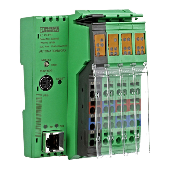
1.1.1. Обзр учебного стенда ilc 130 Starterkit
ILC 130
Starterkit
квлючает:
-
Inline
controller 130 ETH (ILC) ; -
Inline
модуль с двумя аналоговыми входами IB
IL AI 2/SF-ME; -
Потенциометр –
для измерения аналоговых сигналов; -
Модуль тумблеров
– для включения/выключения цифровых
сигналов.
Наглядно ILC
130 Starterkit
представлен на рисунке ниже.
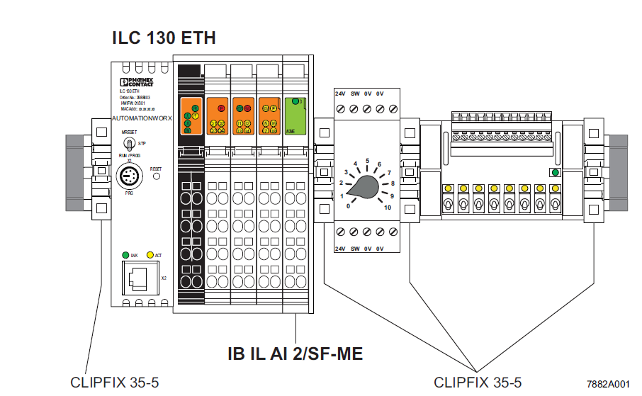
Рис. 1.1 Расположение
компонент на DIN-рейке
Пример прокладки
проводов для входных и выходных сигналов,
а также линий источника питания показано
на рисунке 1.2

Рис.1.2 Пример
электропроводки
ILC
130. Inline
Controller
– компактный контроллер с интегрированным
Ethernet
и INTERBUS
соединением. ILC
130 ETH,
ILC
150 ETH,
ILC
155 ETH
Inline
Controllers
имеют похожий внешний вид и множество
идентичных функций, главная разница
между ними заключается в размере памяти
доступной для использования.
ILC
150 RHT
и ILC
155 ETH
можно применять в потенциально
взрывоопасных зонах.
Контроллер
программируется согласно стандарту
IEC61131 при помощи PC WORX, данный стандарт
описывает 5 языков которые можно применить
для программирования данного контроллера.
Контроллер может
быть подключен к сети Ethernet через которую
с ним можно соединиться по ТСР или UDP
протоколу.
Так же можно
соединить несколько контроллеров в
одну систему при помощи INTERBUS.
Соединения и
рабочие элементы. На
рисунке 1.3 показан внешний вид ILC
130, его компоненты и соединения.
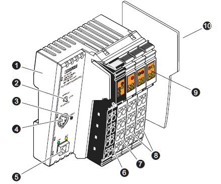
Рис. 1.3 Внешний вид
ILC
130
1 — Корпус
2 – Переключатель
режима – запуск, сброс, перезагрузка.
3 – Кнопка сброса
на заводские настройки.
4 – Разъём RS
— 232 интерфейс
5 – Разъём Ethernet
6 – Коннектор1:
модуль источника питания
7 – Коннектор2:
модуль выходов
8 – Коннектор3-4:
модули входов
9 – Индикатор
статуса
10 – Боковая
накладка.
Диагностика и
индикаторы статуса. Расположение
точек индикации показано на Рис.1.4
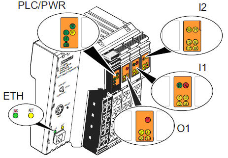
Рис.1.4 Индикаторы
|
Название |
Цвет |
Описание |
|
ETH: |
||
|
LNK |
Green |
Соединение |
|
ON: |
Контроллер |
|
|
ACT |
Yellow |
Передача |
|
ON: |
Передача |
|
|
PLC: |
||
|
FR |
Green |
Контроллер |
|
OFF: |
IEC |
|
|
Flashing: |
IEC |
|
|
ON: |
IEC |
|
|
FF |
Yellow |
Отказ, |
|
ON: |
ошибка |
|
|
OFF: |
нет |
|
|
FR |
Flashing |
Только |
|
PWR: |
||
|
UL |
Green |
24 |
|
ON: |
питание |
|
|
IL: |
||
|
RDY |
Green |
INTERBUS |
|
Flashing: |
INTERBUS |
|
|
ON: |
INTERBUS |
|
|
FAIL |
Red |
Отказ, |
|
ON: |
одна из следующих
-ошибка при — |
|
|
BSA |
Yellow |
Сегмент |
|
ON: |
один |
|
|
PF |
Yellow |
Периферия |
|
ON: |
ошибка |
|
|
I/O: |
||
|
I1 |
Yellow |
входы |
|
ON: |
соответствующие |
|
|
E |
Yellow |
Ошибка |
|
ON: |
короткая |
|
|
Q1 |
Yellow |
Выходы |
|
ON: |
Соответствующие |
Переключатель
режимов. Используется
для задания состояния программы.
RUN/PROG
и STOP
включаются переключением, а MRESET
переключается нажатием. После отпускания
кнопки из состояния MRESET
, она вернется в состояние STOP.
RUN/PROG
программа находится в состоянии
исполнения.
PC
WorX/PC
WorX
Express
может быть использовано для модификации
программы либо её загрузки на контроллер.
STOP
программа находится в состоянии
остановки.
MRESET
временные данные и программа удалены.
С целью безопасности
переключите режим на следующий:
-
переключите на
MRESET
на три секунды. -
отпустите
переключатель на три секунды. -
переключите на
MRESET
на три секунды.
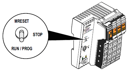
Рис. 1.5 Переключатель
режимов
Цифровые входы
и выходы. Цифровые
входы и выходы
представлены на рис.1.6
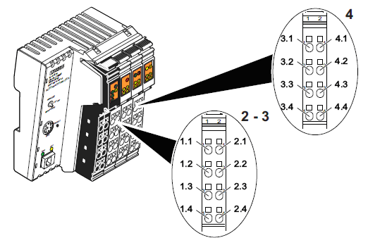
Рис. 1.6 Расположение
входов и выходов
Коннектор 2 точки
выходов
1.1 Q1
выход 1
2.1 Q2
выход 2
1.2, 2.2 GND
заземление для 2 и 3-терминалов
1.3, 2.3 FE
Functional
earth
заземление для 3-терминала
1.4 Q3
выход 3
2.4 Q4
выход 4
Коннектор 3 точки
входов
1.1 I1
вход 1
2.1 I2
вход 2
1.2, 2.2 24
V
питание для 2 и 3-терминала
1.3, 2.3 GND
заземление для 3-терминала
1.4 I3
вход 3
2.4 I4
вход 4
Выходы запитаны
напряжением 24 V
Коннектор 4 точки
входов
3.1 I5
вход 5
4.1 I6
вход 6
3.2, 4.2 24
V
питание для 3-терминала
3.3, 4.3
GND
Ground contact для
3-терминала
3.4 I7
Input 7
4.4 I8
Input 8
PC WorX. PC
WorX программное обеспечение объединяющее
в себе средства для разработки программ
для всех контроллеров от Phoenix Contact,
конфигурирования устройств присоединенных
к шине контроллера и диагностики
контроллера.
Соседние файлы в предмете [НЕСОРТИРОВАННОЕ]
- #
- #
- #
- #
- #
- #
- #
- #
- #
- #
- #
Specifications:
|
Accompanying Data:
Phoenix Contact ILC 130 ETH Controller PDF Operation & User’s Manual (Updated: Monday 27th of March 2023 10:21:47 AM)
Rating: 4.2 (rated by 100 users)
Compatible devices: ELR H51-IESSC-24DC500AC-06, CONTACTRON CSS 0.25-1/3, AXC 3050, Nanoline Series, INTERBUS, RFC 4072R, EV-PLCC-AC1-DC1, AXC 1050.
Recommended Documentation:
Phoenix Contact ILC 130 ETH: Text of Operation & User’s Manual
(Ocr-Read Version Summary of Contents, UPD: 27 March 2023)
-
4, onlinecomponents.com UM EN ILC 1XX PHOENIX CONTACT 7805_en_02 Please observe the following notes In order to ensure the safe use of the product described, you have to read and understand this manual. The following notes provide information on how to use this manual. User group of this manual The use of products described in this manual is oriented exclusively to quali…
-
66, onlinecomponents.com UM EN ILC 1XX 4-6 PHOENIX CONTACT 7805_en_02 4.7 Battery, realtime clock 4.8 Power supplies 4.9 Mode selector switch 4.10 System time Table 4-7 System variables of the battery and realtime clock System variable Type Meaning RTC_BATTERY_LOW BOOL The realtime clock battery is low. RTC_DATA_INVALID BOOL Realtime clock data is invalid. Table 4-8 System variables of the …
-
22, onlinecomponents.com UM EN ILC 1XX 2-12 PHOENIX CONTACT 7805_en_02 Inserting/removing the parameterization memory Figure 2-9 Inserting (A) and removing (B) the parameterization memory Inserting the SD card The ILC 170 ETH 2TX has an SD card holder with push/push technology. • Insert the parameterization memory (SD card) into the slot as shown in Figure 2-9 (A)…
-
17, onlinecomponents.com Description of the Inline Controller 7805_en_02 PHOENIX CONTACT 2-7 ILC 170 ETH 2TX Figure 2-6 Structure of the Inline Controller (ILC 170 ETH 2TX) The Inline Controller consists of the following components: 1 Electronics base 2 Slot for the parameterization memory/card holder (SD card) 3 Mode selector switch 4 Reset button 5 V.24 (RS-232) interface (X1) 6 Ethernet …
-
64, onlinecomponents.com UM EN ILC 1XX 4-4 PHOENIX CONTACT 7805_en_02 4.5 IEC 61131 runtime system There is a separate group of variables for the IEC 61131 runtime system. Table 4-4 System variables of the IEC 61131 runtime system System variable Type Meaning PLCMODE_ON BOOL PLC status ON: The runtime system on the Inline Controller is ready to operate. PLCMODE_RUN BOOL PLC st…
-
35, onlinecomponents.com Description of the Inline Controller 7805_en_02 PHOENIX CONTACT 2-25 The block is activated by setting the REQUEST input. If the data has been copied to the created DATA memory area, DONE is set for one cycle. There is no waiting for data. If no data is present in the receive buffer, a corresponding error is indicated. BUFFER_FULL is reset once REQUEST and DO…
-
33, onlinecomponents.com Description of the Inline Controller 7805_en_02 PHOENIX CONTACT 2-23 Elements of the T_COM_PARAMETER data structure The following describes the elements of the data structure and which settings are supported by the ILC 130 ETH, ILC 150 ETH, ILC 155 ETH, and ILC 170 ETH 2TX Inline Controllers. X : Setting supported – : Setting not supported…
-
32, onlinecomponents.com UM EN ILC 1XX 2-22 PHOENIX CONTACT 7805_en_02 T_COM_PARAMETER data structure The T_COM_PARAMETER data structure is used to specify the settings for initialization. • Program the following structure in your application program. TYPE T_COM_PARAMETER : STRUCT protocol : INT; baudrate : INT; databits : INT; stopbits : INT; flowcontrol : INT; error_…
-
24, onlinecomponents.com UM EN ILC 1XX 2-14 PHOENIX CONTACT 7805_en_02 2.11 Mounting and removing the Inline Controller An Inline station is set up by mounting the individual components side by side. No tools are required. Mounting the components side by side automatically creates potential and bus signal connections between the individual station components. The modules are mounted per…
-
43, onlinecomponents.com Description of the Inline Controller 7805_en_02 PHOENIX CONTACT 2-33 2.15.7 Jumpers Terminals 1.3 and 2.3 on connector 1 can be jumpered if the communications power and the segment power are not to be electrically isolated.
… -
31, onlinecomponents.com Description of the Inline Controller 7805_en_02 PHOENIX CONTACT 2-21 2.13.2 RS232_INIT Figure 2-18 RS232_INIT The RS232_INIT function block is used to parameterize the serial interface. Following successful parameterization, the RS232_SEND and RS232_RECEIVE blocks can be used. The RS232_INIT block must be executed cyclically at least until paramet…
-
78, onlinecomponents.com UM EN ILC 1XX B-2 PHOENIX CONTACT 7805_en_02 Power supply without fall-back characteristic curve ……………. 2-29, 5-1 R Realtime clock…………………………………………………… 3-5 Removal…………………………………………………. 2-14, 2-15 Replacing……………………………………………………..…
Phoenix Contact ILC 130 ETH: Recommended Instructions
AAA-133U2, maxi Tour, SG752, R70I


-
blocstop™ BSO Fall arrest device for suspended material-lifting and rigging installations Fangvorrichtung für hochziehbare Personen- und Materialaufnahmemittel (PAM & MAM) Dispositif antichute pour plateformes suspendues pour levage de personnens et matériel (PSLP & PSLM) Opvangvoorziening voor omhoog trekbare personen- en materiaalhefmiddelen (PAM & MAM) …
blocstop BSO Series 96
-
IQ Switch® ProxSense® Series Copyright © Azoteq (Pty) Ltd 2014. IQS211EV02 Quick start guide Page 1 of 2 All Rights Reserved. Revision 0.01 October 2014 IQS211EV02 Quick start guide Single Channel Capacitive Proximity/Touch Controller with movement detection The IQS211ProxSense® IC is a self-capacitance controller designed for applications where an awake/activate …
IQ Switch — ProxSense Series 3
-
. Maple Systems Inc., 808 134th Street SW, Suite 120, Everett, WA 98204-7333 – www.maplesystems.com 1036-0175 Page 1 of 6 Rev. 01, 03/04/2011 C O N T R O L L E R I N F O R M A T I O N S H E E T Maple Model(s) PLC or Controller HMI5000 Series Allen-Bradley PLC-5/xxE Series (E …
HMI5000 Series 6
-
GLOBAL JET CLUB EUROPE – FINAL-Modellbau email: [email protected] email: [email protected] www.final-modellbau.de ______________________________________________________________________________ Page 1 of 8 Anleitung – JETLEGEND *English version below* ‘Central controller’ Stand: 06.07.2015 1. Schalter und Taster A. Switch Druckknopf ON/OFF (P …
JL500-contr 8
-
USER’S MANUAL Rev. 10/2021008M-RX1-2801PH280ACD Automation S.r.l. Via Picasso, 34/36 — 20025 Legnano (MI)- Italy Tel. +39 0331 577479 — Fax +39 0331 579479E-mail: [email protected] — Web: www.cdautomation.com …
REVEX 1Ph 280A 63
-
Installation and Operation Manual for LW unitsAdvanced programcapabilities.Internal DisplayTerminal (IDT)Multiple communicationinterface options:- LonWorks®- BACnet™ Ethernet- BACnet™ MS/TP- Modbus®Precise temperature and humidity control.CM3540 SeriesController …
CM3540 Series 52
-
Operating Instructionswww.foxunhd.comFX-SMX444x4 Seamless HDMI Matrix With 2×2 Video Wall ControllerDear CustomerThank you for purchasing this product. For optimum performance and safety, please read theseinstructions carefully before connecting, operating or adjusting this product. Please keep this manual forfuture reference.ABLE OF CONTENTSFeatureSpecificationsPackage ContentsPan …
FX-SMX44 12
-
5250 Terminal EmulationPROGRAMMER’SREFERENCE GUIDE» » » » » » » » » » » » » » » » » » » » » » » » » » » «P/N 977-047-039Revision CJuly 1998 …
5250 318
-
USER GUIDE apexDRIVE User Guide 9200162 0v10 1 apexDRIVE Variable Speed Chain Hoist Controller November 2017 Version 0v10 Kinesys Projects Ltd Unit 2 Kempton Gate Business Centre Oldfield Road HAMPTON Middlesex TW12 2AF United Kingdom …
apexDRIVE Series 50
Additional Information:
Popular Right Now:
Operating Impressions, Questions and Answers:
Phoenix Contact Kft.
Oldal 1 / 5
2013.06.04.
Kivonat az online
katalógusból
ILC 130 ETH
Rendelési szám: 2988803
Inline vezérlő Ethernet interfésszel más vezérlőkhöz, ill.
rendszerekhez történő csatlakoztatáshoz és IEC 61131-3
szerinti programozási lehetőséggel, kompletten csatlakozóval és
feliratozómezővel.
Kereskedelmi adat
EAN
4
046356
340120
Csomag
1
Vámtarifa
85371091
Katalógusoldal információ
Oldal 18 (AX-2011)
Termék jegyzetek
WEEE/RoHS-megfelelo: 2008.09.09
Az itt megadott adatok az online
katalógusból származnak.
Teljesköru információkat
és adatokat a felhasználói
dokumentációknál taláhat: http://
www.download.phoenixcontact.com.
Az internetes letöltésekhez eloször el
kell fogadni az általános szerzodési
feltételeket.
Termék leírás
A Phoenix Contact Inline vezérlőinek változatos vezérlőcsaládját a nagy teljesítményű ILC 130 ETH kompakt vezérlővel
egészítették ki. Ezzel a vezérlővel az Inline vezérlők lehetséges alkalmazási területe egészen a kisebb alkalmazásokig
bővül. Az Inline automatizálási rendszerbe történő közvetlen integrálással a kompakt vezérlő változatosan igazítható
a mindenkori igényekhez. A vezérlő az integrált Ethernet interfészen keresztül a PC WorX automatizálási szoftverrel
paraméterezhető és programozható az IEC 61131-re, párhuzamosan képes adatot cserélni OPC-szerverekkel és
kommunikálni TCP/IP-kompatibilis eszközökkel.