-
Contents
-
Table of Contents
-
Bookmarks
Quick Links
Related Manuals for Asus ROG STRIX X570-E GAMING
Summary of Contents for Asus ROG STRIX X570-E GAMING
-
Page 1
ROG STRIX X570-E GAMING… -
Page 2
Product warranty or service will not be extended if: (1) the product is repaired, modified or altered, unless such repair, modification of alteration is authorized in writing by ASUS; or (2) the serial number of the product is defaced or missing. -
Page 3: Table Of Contents
Contents Safety information ………………….. v About this guide ………………….vi ROG STRIX X570-E GAMING specifications summary ……… viii Package contents …………………. xii Installation tools and components …………….. xiii Chapter 1: Product Introduction Motherboard overview …………….1-1 1.1.1 Before you proceed …………..1-1 1.1.2…
-
Page 4
3.6.12 AMD CBS ……………… 3-17 Monitor menu ………………. 3-18 Boot menu ………………..3-18 Tool menu ………………..3-19 3.9.1 ASUS EZ Flash 3 Utility …………3-19 3.9.2 ASUS Secure Erase…………..3-19 3.9.3 ASUS User profile …………..3-21 3.9.4 ASUS SPD Information …………. 3-21 3.9.5… -
Page 5: Safety Information
Safety information Electrical safety • To prevent electrical shock hazard, disconnect the power cable from the electrical outlet before relocating the system. • When adding or removing devices to or from the system, ensure that the power cables for the devices are unplugged before the signal cables are connected. If possible, disconnect all power cables from the existing system before you add a device.
-
Page 6: About This Guide
Refer to the following sources for additional information and for product and software updates. ASUS website The ASUS website (www.asus.com) provides updated information on ASUS hardware and software products. Optional documentation Your product package may include optional documentation, such as warranty flyers, that may have been added by your dealer.
-
Page 7
Conventions used in this guide To ensure that you perform certain tasks properly, take note of the following symbols used throughout this manual. DANGER/WARNING: Information to prevent injury to yourself when trying to complete a task. CAUTION: Information to prevent damage to the components when trying to complete a task. -
Page 8: Rog Strix X570-E Gaming Specifications Summary
— 4 x DIMM, max. 128GB, DDR4 3200(O.C.)/3000(O.C.)/2933(O.C.)/280 0(O.C.)/2666/2400/2133 MHz, un-buffered memory Dual channel memory architecture * Refer to www.asus.com for the Memory QVL (Qualified Vendors List). Gen AMD Ryzen™ Processors 2 x PCIe 4.0 x16 SafeSlots (supports x16, x8/x8) Gen AMD Ryzen™…
-
Page 9
ROG STRIX X570-E GAMING specifications summary Gen AMD Ryzen™ Processors — 1 x M.2 Socket 3 with M Key, Type 2242/2260/2280/22110 storage devices support (PCIE 4.0 x 4 and SATA modes) Gen AMD Ryzen™/2 and 1 Gen AMD Ryzen™ with Radeon™… -
Page 10
ROG STRIX X570-E GAMING specifications summary Gen AMD Ryzen Processors — 4 x USB 3.2 Gen2 ports (4 ports at back panel, Type-A) Gen AMD Ryzen and 1 Gen AMD Ryzen™ with Radeon™ Vega Graphics Processors — 4 x USB 3.2 Gen1 ports (4 ports at back panel, Type-A) AMD X570 chipset — 1 x USB 3.2 Gen2 front panel connector… -
Page 11
ROG STRIX X570-E GAMING specifications summary Gamer’s Guardian — DRAM Overcurrent Protection — ESD Guards on LAN, Audio, KBMS and USB ports Special Features — Highly Durable Components — SafeSlot — Procool — DIGI+ VRM 1 x HDMI port 1 x DisplayPort… -
Page 12: Package Contents
1 x Extension Cable for RGB strips Cables 1 x Extension Cable for RGB Addressable strips 1 x Thermistor cable 1 x ASUS 2×2 dual band Wi-Fi antenna 1 x 2-in-1 M.2 Screws Package 1 x ROG STRIX door hanger Accessories…
-
Page 13: Installation Tools And Components
Installation tools and components 1 Bag of screws Phillips (cross) screwdriver PC chassis Power supply unit AMD AM4 CPU AMD AM4/AM3 compatible CPU Fan DDR4 DIMM SATA hard disk drive SATA optical disc drive (optional) Graphics card (optional) The tools and components in the table above are not included in the motherboard package. xiii…
-
Page 15: Chapter 1: Product Introduction
Chapter 1: Product Introduction Product Introduction Motherboard overview 1.1.1 Before you proceed Take note of the following precautions before you install motherboard components or change any motherboard settings. • Unplug the power cord from the wall socket before touching any component. • Before handling components, use a grounded wrist strap or touch a safely grounded object or a metal object, such as the power supply case, to avoid damaging them due to static electricity. • Hold components by the edges to avoid touching the ICs on them. • Whenever you uninstall any component, place it on a grounded antistatic pad or in the bag that came with the component. • Before you install or remove any component, ensure that the ATX power supply is switched off or the power cord is detached from the power supply. Failure to do so may cause severe damage to the motherboard, peripherals, or components. ASUS ROG STRIX X570-E GAMING…
-
Page 16: Motherboard Layout
1.1.2 Motherboard layout 24.4cm(9.6in) RGB_HEADER1 AIO_PUMP EATX12V_2 EATX12V_1 HDMI_DP CPU_FAN CPU_OPT BOOT DIGI +VRM DRAM BIOS_FLBK FLBK_LED U32G2_1-4 LAN2_U32G2_56 U32G2_C8 LAN1_U32G2_7 M.2(WIFI) SPI_TPM AUDIO STRIX X570-e GAMING 8125-CG 22110 2280 2260 2242 PCIEX16_1 Intel ® I211AT PCH_LED1 PCH_LED3 PCH_LED2 ® Super PCIE_X1_1 X570…
-
Page 17
15. USB 3.2 Gen1 front panel connector (U32G1_1011) 1-15 16. USB 2.0 connectors (10-1 pin USB12, USB34) 1-16 17. Thermal sensor connector (2-pin T_SENSOR) 1-13 18. NODE connector (12-1 pin NODE) 1-21 19. Q-Code LED 1-10 20. Front panel audio connector (10-1 pin AAFP) 1-13 21. PCIe 4.0/3.0 x16 slot (PCIE_X16_1/2/3) 22. PCIe 4.0 x1 slot (PCIE_X1_1/2) 23. PCH LED 24. PCH fan connectors (4-pin PCH_FAN) 1-22 25. LED connector (13-pin LED1_CON1) 1-16 26. BIOS Flashback LED (FLBK_LED) 27. BIOS Flashback button (BIOS_FLBK) 2-13 ASUS ROG STRIX X570-E GAMING… -
Page 18: Central Processing Unit (Cpu)
1.1.3 Central Processing Unit (CPU) The motherboard comes with an AM4 socket designed for AMD AM4 Socket for 3 and 2 Gen AMD Ryzen and 1 Gen AMD Ryzen™ with Radeon™ Vega Graphics Processors. STRIX X570-e GAMING ROG STRIX X570-E GAMING CPU socket AM4 The AM4 socket has a different pinout design. Ensure that you use a CPU designed for the AM4 socket. The CPU fits in only one correct orientation. DO NOT force the CPU into the socket to prevent bending the connectors on the socket and damaging the CPU! Ensure that all power cables are unplugged before installing the CPU. 1.1.4 System memory The motherboard comes with four Double Data Rate 4 (DDR4) Dual Inline Memory Modules (DIMM) slots. A DDR4 module is notched differently from a DDR, DDR2, or DDR3 module. DO NOT install a DDR, DDR2, or DDR3 memory module to the DDR4 slot. STRIX X570-e GAMING ROG STRIX X570-E GAMING 288-pin DDR4 DIMM sockets…
-
Page 19
Recommended memory configurations Memory configurations You may install 2 GB, 4 GB, 8 GB, and 16 GB unbuffered DDR4 DIMMs into the DIMM sockets. • You may install varying memory sizes in Channel A and Channel B. The system maps the total size of the lower-sized channel for the dual-channel configuration. Any excess memory from the higher-sized channel is then mapped for single-channel operation. • This motherboard does not support DIMMs made up of 512 Mb (64 MB) chips or less (Memory chip capacity counts in Megabit, 8 Megabit/Mb = 1 Megabyte/MB). • The default memory operation frequency is dependent on its Serial Presence Detect (SPD), which is the standard way of accessing information from a memory module. Under the default state, some memory modules for overclocking may operate at a lower frequency than the vendor-marked value. • For system stability, use a more efficient memory cooling system to support a full memory load (4 DIMMs) or overclocking condition. • Always install the DIMMS with the same CAS Latency. For an optimum compatibility, we recommend that you install memory modules of the same version or data code (D/C) from the same vendor. Check with the vendor to get the correct memory modules. ASUS ROG STRIX X570-E GAMING… -
Page 20: Expansion Slots
1.1.5 Expansion slots Unplug the power cord before adding or removing expansion cards. Failure to do so may cause you physical injury and damage motherboard components. STRIX X570-e GAMING PCIEX16_1 PCIE_X1_1 PCIEX16_2 PCIE_X1_2 PCIEX16_3 Slot No. Slot Description PCIe 4.0/3.0 x16_1 slot PCIe 4.0 x1_1 slot PCIe 4.0/3.0 x16_2 slot PCIe 4.0 x1_2 slot PCIe 4.0 x16_3 slot Chapter 1: Product Introduction…
-
Page 21
PCIe x16_2 PCIe x16_3 x4 (PCIe 4.0) M.2_1 (PCIe Mode) x4 (PCIe 4.0) x4 (PCIe 4.0) x4 (PCIe 4.0) M.2_1 (SATA Mode) Support Support Support M.2_2 (PCIe Mode) x4 (PCIe 4.0) x4 (PCIe 4.0) x4 (PCIe 4.0) M.2_2 (SATA Mode) Support Support Support • PCIex16_2 shares bandwidth with PCIex16_3. • We recommend that you provide sufficient power when running CrossFireX or SLI ® mode. • Ensure to connect the 8-pin and 4-pin power plugs when running CrossFireX or SLI mode. • Connect chassis fans to the motherboard chassis fan connectors when using multiple graphics cards for better thermal environment. ASUS ROG STRIX X570-E GAMING… -
Page 22: Onboard Leds
STRIX X570-e GAMING ROG STRIX X570-E GAMING CPU/ DRAM/ BOOT/ VGA LED The order which the LEDs light up may vary per CPU. Standby Power LED (SB_PWR) The motherboard comes with a standby power LED. The LED lights up to indicate that the system is ON, in sleep mode, or in soft-off mode. This is a reminder that you should shut down the system and unplug the power cable before removing or plugging in any motherboard component. The illustration below shows the location of the onboard LED. STRIX X570-e GAMING SB_PWR Standby Power Powered Off ROG STRIX X570-E GAMING Standby power LED Chapter 1: Product Introduction…
-
Page 23
PCH LED The motherboard comes with six standby power LED. The illustration below shows the location of the onboard PCH LED. STRIX X570-e GAMING PCH LED Lighting ROG STRIX X570-E GAMING PCH_LED Lighting BIOS Flashback LED (FLBK_LED) The FLBK LED lights when the USB Flashback button is pressed for three seconds. FLBK_LED STRIX X570-e GAMING ROG STRIX X570-E GAMING FLBK_LED ASUS ROG STRIX X570-E GAMING… -
Page 24: Headers
ROG STRIX X570-E GAMING Q-Code LED 1.1.7 Headers Clear RTC RAM jumper (2-pin CLRTC) This jumper allows you to clear the CMOS RTC RAM data of the system setup information such as date, time, and system passwords. STRIX X570-e GAMING CLRTC PIN 1 ROG STRIX X570-E GAMING Clear RTC RAM To erase the RTC RAM: Turn OFF the computer and unplug the power cord. Use a metal object such as a screwdriver to short the two pins. Plug the power cord and turn ON the computer. Hold down the <Del> key during the boot process and enter BIOS setup to re-enter data. If the steps above do not help, remove the onboard battery and short the two pins again to clear the CMOS RTC RAM data. After clearing the CMOS, reinstall the battery. Chapter 1: Product Introduction…
-
Page 25
AURA RGB header (4-pin RGB_HEADER1/2) These connectors are for RGB LED strips. RGB_HEADER1 PIN 1 +12V G R B RGB_HEADER2 PIN 1 +12V G R B STRIX X570-e GAMING ROG STRIX X570-E GAMING RGB_HEADER connectors The RGB header supports 5050 RGB multi-color LED strips (12V/G/R/B), with a maximum power rating of 3A (12V), and no longer than 3 m. Before you install or remove any component, ensure that the ATX power supply is switched off or the power cord is detached from the power supply. Failure to do so may cause severe damage to the motherboard, peripherals, or components. • Actual lighting and color will vary with LED strip. • If your LED strip does not light up, check if the RGB LED extension cable and the RGB LED strip is connected in the correct orientation, and the 12V connector is aligned with the 12V header on the motherboard. -
Page 26
Addressable RGB header (4-1 pin ADD_GEN2_1/2) These connectors are for individually addressable RGB WS2812B LED strips with embedded WS2811LED driver ICs. ADD_GEN2_1 Ground Data PIN 1 STRIX X570-e GAMING ADD_GEN2_2 PIN 1 ROG STRIX X570-E GAMING ADD_HEADER headers The addressable RGB header supports WS2812B addressable RGB LED strips (5V/Data/ Ground), with a maximum power rating of 3A (5V) and a maximum of 120 LEDs. Before you install or remove any component, ensure that the ATX power supply is switched off or the power cord is detached from the power supply. Failure to do so may cause severe damage to the motherboard, peripherals, or components. • Actual lighting and color will vary with LED strip. • If your LED strip does not light up, check if the addressable RGB LED strip is connected in the correct orientation, and the 5V connector is aligned with the 5V header on the motherboard. • The addressable RGB LED strip will only light up under the operating system. • The addressable RGB LED strip is purchased separately. -
Page 27: Internal Connectors
ROG STRIX X570-E GAMING T_SENSOR connector 1.1.8 Internal connectors Front panel audio connector (10-1 pin AAFP) This connector is for a chassis-mounted front panel audio I/O module that supports HD Audio. Connect one end of the front panel audio I/O module cable to this connector. AAFP STRIX X570-e GAMING HD-audio-compliant pin definition ROG STRIX X570-E GAMING Analog front panel connector We recommend that you connect a high-definition front panel audio module to this connector to avail of the motherboard’s high-definition audio capability. ASUS ROG STRIX X570-E GAMING 1-13…
-
Page 28
RSATA_RXN6 STRIX X570-e GAMING RSATA_RXP5 RSATA_RXP6 SATA6G_7 SATA6G_8 RSATA_TXP7 RSATA_TXP8 RSATA_TXN7 RSATA_TXN8 RSATA_RXN7 RSATA_RXN8 RSATA_RXP7 RSATA_RXP8 ROG STRIX X570-E GAMING SATA 6 Gb/s connectors • These connectors are set to [AHCI] by default. If you intend to create a Serial ATA RAID set using these connectors, set the SATA Mode Selection item in the BIOS to [RAID]. • Before creating a RAID set, refer to section RAID configurations or the manual bundled in the motherboard support DVD. • When using NCQ, set the SATA Mode in the BIOS to [AHCI]. Refer to section SATA Configuration for details. Chapter 1: Product Introduction 1-14… -
Page 29
USB3.2 Gen2 front panel connector The USB 3.2 Gen2 module is purchased separately. USB 3.2 Gen1 connector (20-1 pin U32G1_1011) This connector allows you to connect a USB 3.2 Gen1 module for additional USB 3.2 Gen1 front or rear panel ports. With an installed USB 3.2 Gen1 module, you can enjoy all the benefits of USB 3.2 Gen1 including faster data transfer speeds of up to 5 Gb/s, faster charging time for USB-chargeable devices, optimized power efficiency, and backward compatibility with USB 2.0. U32G1_1011 STRIX X570-e GAMING PIN 1 ROG STRIX X570-E GAMING USB 3.2 Gen1 connectors The USB 3.2 Gen1 module is purchased separately. The plugged USB 3.2 Gen1 device may run on xHCI or EHCI mode depending on the operating system’s setting. ASUS ROG STRIX X570-E GAMING 1-15… -
Page 30
These connectors are for USB 2.0 ports. Connect the USB module cable to any of these connectors, then install the module to a slot opening at the back of the system chassis. These USB connectors comply with USB 2.0 specification that supports up to 480 Mb/s connection speed. USB34 USB12 STRIX X570-e GAMING PIN 1 PIN 1 ROG STRIX X570-E GAMING USB2.0 connectors Never connect a 1394 cable to the USB connectors. Doing so will damage the motherboard! LED connector (13-pin LED1_CON1) This connector is for connecting the LED strip on your back I/O cover. LED1_CON STRIX X570-e GAMING ROG STRIX X570-E GAMING LED_CON Chapter 1: Product Introduction 1-16… -
Page 31
System panel connectors (10-1 pin F_PANEL; 4-pin SPEAKER) These connectors supports several chassis-mounted functions. STRIX X570-e GAMING ROG STRIX X570-E GAMING SPEAKER & F_PANEL connectors • System power LED (2-pin PLED) This 2-pin connector is for the system power LED. Connect the chassis power LED cable to this connector. The system power LED lights up when you turn on the system power, and blinks when the system is in sleep mode. • Hard disk drive activity LED (2-pin +HDLED) This 2-pin connector is for the HDD Activity LED. Connect the HDD Activity LED cable to this connector. The HDD LED lights up or flashes when data is read from or written to the HDD. • System warning speaker (4-pin SPEAKER) This 4-pin connector is for the chassis-mounted system warning speaker. The speaker allows you to hear system beeps and warnings. • ATX power button/soft-off button (2-pin PWRBTN) This connector is for the system power button. Pressing the power button turns the system on or puts the system in sleep or soft-off mode depending on the BIOS settings. Pressing the power button for more than four seconds while the system is ON turns the system OFF. -
Page 32
Connect the fan cables to the fan connectors on the motherboard, ensuring that the black wire of each cable matches the ground pin of the connector. CPU_FAN AIO_PUMP CPU_OPT CHA_FAN1 CHA_FAN2 W_PUMP+ CHA FAN PWM CHA FAN IN CHA FAN PWR STRIX X570-e GAMING M.2_FAN ROG STRIX X570-E GAMING Fan connectors • DO NOT forget to connect the fan cables to the fan connectors. Insufficient air flow inside the system may damage the motherboard components. These are not jumpers! Do not place jumper caps on the fan connectors! • Ensure to fully insert the 4-pin CPU fan cable to the CPU fan connector. • Connect the pump cable from the all-in-one cooler (AIO cooler) to the AIO_PUMP header, and connect the fan cables to the CPU_FAN and/or CPU_OPT header(s). • W_PUMP+ function support depends on water cooling device. Header Max. Current Max. -
Page 33
-5 Volts PIN 1 PIN 1 +5 Volts STRIX X570-e GAMING +5 Volts PSON# +3 Volts -12 Volts +3 Volts +3 Volts PIN 1 ROG STRIX X570-E GAMING power connectors • DO NOT connect the 4-pin power plug only, the motherboard may overheat under heavy usage. • Ensure to connect the 8-pin power plug, or connect both the 8-pin and 4-pin power plugs. • For a fully configured system, we recommend that you use a power supply unit (PSU) that complies with ATX 12 V Specification 2.0 (or later version) and provides a minimum power of 350 W. •… -
Page 34
M.2 sockets (M.2_1; M.2_2) These sockets allow you to install M.2 SSD modules. M.2_1(SOCKET3) 22110 2280 2260 2242 M.2_2(SOCKET3) STRIX X570-e GAMING 22110 2280 2260 2242 ROG STRIX X570-E GAMING M.2 sockets • For 3 Generation AMD Ryzen™ processors, the M.2 socket 3 supports PCIe 4.0 x4 mode and SATA mode M Key design and type 2242 / 2260 / 2280 / 22110 storage devices. • For 2 Generation AMD Ryzen™ /2 and 1 Generation AMD Ryzen™ with Radeon™ Vega Graphics processors, the M.2 socket 3 supports PCIe 3.0 x4 mode and SATA mode M Key design and type 2242 / 2260 / 2280 / 22110 storage devices. • For AMD X570 chipset, the M.2 socket 3 supports PCIe 4.0 x4 mode and SATA mode M Key design and type 2242/ 2260/ 2280 / 22110 storage devices. The M.2 SSD module is purchased separately. -
Page 35
SPI FLASH WP# +18V SPI SPI CLK SPI CS# SPI MISO SPI MOSI SPI HOLD# ROG STRIX X570-E GAMING SPI TPM connector The SPI TPM module is purchased separately. NODE connector (12-1 pin NODE) This connector allows you to connect a compatible PSU or control a compatible fan extension card. STRIX X570-e GAMING ROG STRIX X570-E GAMING Node connector ASUS ROG STRIX X570-E GAMING… -
Page 36
PCH fan connector (4 pin PCH_FAN) The PCH Fan connector is for connecting the PCH fan on your PCH cover. PCH_FAN STRIX X570-e GAMING PIN 1 ROG STRIX X570-E GAMING PCH FAN header Chapter 1: Product Introduction 1-22… -
Page 37: Chapter 2: Basic Installation
Place the motherboard into the chassis, ensuring that its rear I/O ports are aligned to the chassis’ rear I/O panel. Remove the screws that secure the PCH cover (A), then remove the PCH cover (B). ASUS ROG STRIX X570-E GAMING…
-
Page 38
Remove the screws that secure the M.2 heatsink (A), then remove the M.2 heatsink (B). Place nine (9) screws into the holes indicated by circles to secure the motherboard to the chassis. STRIX X570-e GAMING DO NOT over tighten the screws! Doing so can damage the motherboard. Chapter 2: Basic Installation… -
Page 39: Cpu Installation
The AMD AM4 socket is compatible with AMD AM4 processors. Ensure you use a CPU designed for the AM4 socket. The CPU fits in only one correct orientation. DO NOT force the CPU into the socket to prevent bending the connectors on the socket and damaging the CPU! ASUS ROG STRIX X570-E GAMING…
-
Page 40: Cpu Heatsink And Fan Assembly Installation
2.1.3 CPU heatsink and fan assembly installation Apply the Thermal Interface Material to the CPU heatsink and CPU before you install the heatsink and fan if necessary. CPU Heatsink and fan assembly Type 1 Chapter 2: Basic Installation…
-
Page 41
CPU Heatsink and fan assembly Type 2 When using this type of CPU fan, remove the screws and the retention module only. Do not remove the plate on the bottom. ASUS ROG STRIX X570-E GAMING… -
Page 42
To install an AIO cooler AIO_PUMP CPU_FAN CPU_OPT Chapter 2: Basic Installation… -
Page 43: Dimm Installation
2.1.4 DIMM installation To remove a DIMM ASUS ROG STRIX X570-E GAMING…
-
Page 44: Atx Power Connection
2.1.5 ATX power connection • DO NOT connect the 4-pin power plug only, the motherboard may overheat under heavy usage. • Ensure to connect the 8-pin power plug, or connect both the 8-pin and 4-pin power plugs. 2.1.6 SATA device connection Chapter 2: Basic Installation…
-
Page 45: Front I/O Connector
This connector will only fit in one orientation. Push the connector until it clicks into place. To install front panel audio connector To install USB 2.0 connector AAFP USB 2.0 To install system speaker connector ASUS ROG STRIX X570-E GAMING…
-
Page 46: Expansion Card Installation
2.1.8 Expansion card installation To install PCIe x16 cards To install PCIe x1 cards Chapter 2: Basic Installation 2-10…
-
Page 47: Installation
2.1.9 M.2 installation Supported M.2 type varies per motherboard. M.2 installation Before securing the motherboard to the chassis, please remove the PCH cover first and then the M.2 heatsink. ASUS ROG STRIX X570-E GAMING 2-11…
-
Page 48: Wi-Fi Antenna Installation
2.1.10 Wi-Fi antenna installation Installing the ASUS 2×2 dual band W-Fi antennas Connect the bundled ASUS 2×2 dual band Wi-Fi antennas to the Wi-Fi ports at the back of the chassis. • Ensure that the ASUS 2×2 dual band Wi-Fi antennas are securely installed to the Wi-Fi ports.
-
Page 49
• Updating BIOS may have risks. If the BIOS program is damaged during the process and results to the system’s failure to boot up, please contact your local ASUS Service Center. ASUS ROG STRIX X570-E GAMING… -
Page 50: Motherboard Rear And Audio Connections
Motherboard rear and audio connections 2.3.1 Rear I/O connection Rear panel connectors DisplayPort USB 3.2 Gen2 ports 1~4 2.5G LAN (RJ-45) port* LAN (RJ-45) port* Wi-Fi 802.11 a/b/g/n/ac/ax, Bluetooth V5.0 Audio I/O ports** Optical S/PDIF OUT port USB 3.2 Gen2 Type-C port C8 USB 3.2 Gen2 port 7 USB 3.2 Gen2 ports 5 and 6…
-
Page 51
Front Speaker Out Lime Front Speaker Out Mic In Mic In Mic In Pink Mic In Orange – – Center/Sub woofer Center/Sub woofer Black – Rear Speaker Out Rear Speaker Out Rear Speaker Out ASUS ROG STRIX X570-E GAMING 2-15… -
Page 52: Audio I/O Connections
2.3.2 Audio I/O connections Audio I/O ports Connect to Headphone and Mic Connect to Stereo Speakers Connect to 2-channel Speakers Chapter 2: Basic Installation 2-16…
-
Page 53
Connect to 4-channel Speakers Connect to 5.1-channel Speakers Connect to 7.1-channel Speakers ASUS ROG STRIX X570-E GAMING 2-17… -
Page 54: Starting Up For The First Time
Starting up for the first time After making all the connections, replace the system case cover. Ensure that all switches are off. Connect the power cord to the power connector at the back of the system chassis. Connect the power cord to a power outlet that is equipped with a surge protector. Turn on the devices in the following order: Monitor External SCSI devices (starting with the last device on the chain)
-
Page 55: Chapter 3: Bios Setup
BIOS Setup Knowing BIOS The new ASUS UEFI BIOS is a Unified Extensible Interface that complies with UEFI architecture, offering a user-friendly interface that goes beyond the traditional keyboard- only BIOS controls to enable a more flexible and convenient mouse input. You can easily navigate the new UEFI BIOS with the same smoothness as your operating system.
-
Page 56: Bios Setup Program
RTC RAM via the Clear CMOS button. • The BIOS setup program does not support the Bluetooth devices. Please visit ASUS website for the detailed BIOS content manual. BIOS menu screen The BIOS Setup program can be used under two modes: EZ Mode and Advanced Mode.
-
Page 57: Advanced Mode
Qfan Control(F6) Search(F9) Scroll bar Go back to EZ Mode General help Hot Keys Configuration fields Submenu items Pop-up Menu Search on the FAQ Last modified settings Displays the CPU temperature, CPU, and memory voltage output ASUS ROG STRIX X570-E GAMING…
-
Page 58
Menu bar The menu bar on top of the screen has the following main items: My Favorites For saving the frequently-used system settings and configuration. Main For changing the basic system configuration Ai Tweaker For changing the overclocking settings Advanced For changing the advanced system settings For displaying the system temperature, power status, and changing Monitor… -
Page 59
Move your mouse over this button to show a QR code, scan this QR code on your mobile device to connect to the BIOS FAQ web page of the ASUS support website. You can also scan the following QR code: Hot keys This button above the menu bar contains the navigation keys for the BIOS setup program. -
Page 60: Ez Mode
3.2.2 EZ Mode The EZ Mode provides you an overview of the basic system information, and allows you to select the display language, system performance, mode and boot device priority. To switch from Advanced Mode to EZ Mode, click EZ Mode(F7) or press the <F7> hotkey. Displays the CPU/motherboard temperature, CPU voltage output, CPU/chassis fan speed, and SATA information…
-
Page 61: Q-Fan Control
PWM Mode Select a profile to Click to apply the fan setting apply to your fans Click to undo the Click to go back to main menu changes Select to manually configure your fans ASUS ROG STRIX X570-E GAMING…
-
Page 62
Configuring fans manually Select Manual from the list of profiles to manually configure your fans’ operating speed. Speed points Select to manually configure your fans To configure your fans: Select the fan that you want to configure and to view its current status. Click and drag the speed points to adjust the fans’… -
Page 63: Ez Tuning Wizard
To start OC Tuning: Press <F11> on your keyboard or click from the BIOS screen to open EZ Tuning Wizard screen, and then click Next. Select a PC scenario Daily Computing or Gaming/Media Editing, and then click Next. ASUS ROG STRIX X570-E GAMING…
-
Page 64: My Favorites
Select a Main Cooling System BOX cooler, Tower cooler, Water cooler, or I’m not sure, and then click Next. After selecting the Main Cooling System, click Next then click Yes to start the OC Tuning. My Favorites My Favorites is your personal space where you can easily save and access your favorite BIOS items.
-
Page 65
You cannot add user-managed items such as language and boot order to My Favorites. Click Exit (ESC) or press <Esc> key to close Setup Tree Map screen. Go to My Favorites menu to view the saved BIOS items. ASUS ROG STRIX X570-E GAMING 3-11… -
Page 66: Main Menu
Main menu The Main menu screen appears when you enter the Advanced Mode of the BIOS Setup program. The Main menu provides you an overview of the basic system information, and allows you to set the system date, time, language, and security settings. Security The Security menu items allow you to change the system security settings.
-
Page 67: Advanced Menu
EPU Power Saving Mode The ASUS EPU (Energy Processing Unit) sets the CPU in its minimum power consumption settings. Enable this item to set lower CPU core/cache voltage and achieve the best energy saving condition. Configuration options: [Disabled] [Enabled] This item allows you to automatically overclock the CPU and DRAM frequencies and voltage for an enhanced system performance.
-
Page 68: Bixby Ide Configuration
PSS Support This item allows you enable or disable the generation of ACPI_PPC, _PSS, and _PCT objects. Configuration options: [Disabled] [Enabled] NX Mode This item allows you enable or disable no-execute page protection function. Configuration options: [Disabled] [Enabled] SVM Mode This item allows you enable or disable CPU Virtualization.
-
Page 69: Onboard Devices Configuration
Configuration options: [All On] [Stealth] [Aura Only] [Aura Off] Q-Code LED Funtion [Disabled] Turns off Q-Code LED. [POST Code Only] Show POST (POWER-On Self-Test) code on Q-Code LED. [Auto] Automatically display POST (POWER-On Self-Test) code and CPU temperature on Q-Code LED. ASUS ROG STRIX X570-E GAMING 3-15…
-
Page 70: Apm Configuration
When system is in sleep, hibernate or soft off states This item allows you to turn the RGB LED lighting on or off when the system is in the sleep, hibernate or soft off states. Configuration options: [All On] [Stealth] [Aura Only] [Aura Off] Realtek 2.5G LAN Controller This item allows you to enable or disable the Realtek 2.5G LAN controllers.
-
Page 71: Pci Subsytem Settings
Network Stack Configuration The items in this menu allow you to enable or disable the UEFI network stack. 3.6.12 AMD CBS The items in this menu allow you to configure the AMD CBS Setup page. ASUS ROG STRIX X570-E GAMING 3-17…
-
Page 72: Monitor Menu
Monitor menu The Monitor menu displays the system temperature/power status, and allows you to change the fan settings. Q-Fan Configuration The subitems in this menu allow you to configure the Q-Fan features. Qfan Tuning Click this item to automatically detect the lowest speed and configure the minimum duty cycle for each fan.
-
Page 73: Tool Menu
3.9.1 ASUS EZ Flash 3 Utility This item allows you to run ASUS EZ Flash 3. When you press <Enter>, a confirmation message appears. Use the left/right arrow key to select between [Yes] or [No], then press <Enter> to confirm your choice.
-
Page 74
Check the ASUS support site for a full list of SSDs tested with ASUS Secure Erase. The drive may become unstable if you run ASUS Secure Erase on an incompatible SSD. The time to erase the contents of your SSD may take a while depending on its size. Do not turn off the system during the process. -
Page 75: Asus User Profile
GPU Post This item displays the information and recommended configuration for the PCIE slots that the graphics card is installed in your system. This feature is only supported on selected ASUS graphics cards. 3.9.6 ASUS Armoury Crate This item allows you to enable Armoury Crate download process. Armoury Crate app can help you manage and download the latest ROG drivers and utilities updates for your motherboard.
-
Page 76: Exit Menu
® ASUS EZ Flash 3: Updates the BIOS using a USB flash drive. ASUS CrashFree BIOS 3: Restores the BIOS using the motherboard support DVD or a USB flash drive when the BIOS file fails or gets corrupted. 3.11.1…
-
Page 77: Asus Ez Flash 3
3.11.2 ASUS EZ Flash 3 ASUS EZ Flash 3 allows you to download and update to the latest BIOS through the Internet without having to use a bootable floppy disk or an OS-based utility. Updating through the Internet varies per region and Internet conditions. Check your local Internet connection before updating through the Internet.
-
Page 78
To update the BIOS by Internet: Enter the Advanced Mode of the BIOS setup program. Go to the Tool menu to select ASUS EZ Flash Utility and press <Enter>. Select via Internet. Press the Left/Right arrow keys to select an Internet connection method, and then press <Enter>. -
Page 79: Asus Crashfree Bios 3
The BIOS file in the motherboard support DVD may be older than the BIOS file published on the ASUS official website. If you want to use the newer BIOS file, download the file at https://www.asus.com/support/ and save it to a USB flash drive.
-
Page 80
Chapter 3: BIOS Setup 3-26… -
Page 81: Chapter 4: Raid Support
The motherboard comes with the RaidXpert2 Configuration Utility that supports Volume, RAIDABLE, RAID 0, RAID 1, and RAID 10 (depends on system licensing) configurations. For more information on configuring your RAID sets, please refer to the RAID Configuration Guide which you can find at https://www.asus.com/support. 4.1.1 RAID definitions Volume provides the ability to link-together storage from one or several disks, regardless of the size of the space on those disks.
-
Page 82
Chapter 4: RAID Support… -
Page 83: Appendix
CPU self test failed or possible CPU cache error CPU micro-code is not found or micro-code update is failed Internal CPU error Reset PPI is not available 5C – 5F Reserved for future AMI error codes (continued on the next page) ASUS ROG STRIX X570-E GAMING…
-
Page 84: Q-Code Table
Q-Code table Code Description S3 Resume is stared (S3 Resume PPI is called by the DXE IPL) S3 Boot Script execution Video repost OS S3 wake vector call Reserved for future AMI progress codes E4 – E7 S3 Resume Failed S3 Resume PPI not Found S3 Resume Boot Script Error S3 OS Wake Error…
-
Page 85
Reserved for ASL (see ASL Status Codes section below) Ready To Boot event Legacy Boot event Exit Boot Services event Runtime Set Virtual Address MAP Begin Runtime Set Virtual Address MAP End Legacy Option ROM Initialization System Reset (continued on the next page) ASUS ROG STRIX X570-E GAMING… -
Page 86
Q-Code table Code Description USB hot plug PCI bus hot plug Clean-up of NVRAM Configuration Reset (reset of NVRAM settings) B8– BF Reserved for future AMI codes CPU initialization error System Agent initialization error PCH initialization error Some of the Architectural Protocols are not available PCI resource allocation error. -
Page 87: Notices
20 cm from all persons and must not be co-located or operating in conjunction with any other antenna or transmitter. End-users and installers must be provide with antenna installation instructions and transmitter operating conditions for satisfying RF exposure compliance. ASUS ROG STRIX X570-E GAMING…
-
Page 88
Compliance Statement of Innovation, Science and Economic Development Canada (ISED) This device complies with Innovation, Science and Economic Development Canada licence exempt RSS standard(s). Operation is subject to the following two conditions: (1) this device may not cause interference, and (2) this device must accept any interference, including interference that may cause undesired operation of the device. -
Page 89
ASUS Recycling/Takeback Services ASUS recycling and takeback programs come from our commitment to the highest standards for protecting our environment. We believe in providing solutions for you to be able to responsibly recycle our products, batteries, other components as well as the packaging materials. -
Page 90
NCC: Taiwan Wireless Statement 經型式認證合格之低功率射頻電機,非經許可,公司、商號或使用者均不得擅自變更頻 率、加大功率或變更原設計之特性及功能。低功率射頻電機之使用不得影響飛航安全及干 擾合法通信;經發現有干擾現象時,應立即停用,並改善至無干擾時方得繼續使用。前項 合法通信,指依電信法規定作業之無線電通信。低功率射頻電機須忍受合法通信或工業、 科學及醫療用電波輻射性電機設備之干擾。 應避免影響附近雷達系統之操作。 Japan RF Equipment Statement 屋外での使用について 本製品は、 5GHz帯域での通信に対応しています。 電波法の定めにより5.2GHz、 5.3GHz帯域の電 波は屋外で使用が禁じられています。 法律および規制遵守 本製品は電波法及びこれに基づく命令の定めるところに従い使用してください。 日本国外では、 その国の法律または規制により、 本製品の使用ができないことがあります。 このような国では、 本 製品を運用した結果、 罰せられることがありますが、 当社は一切責任を負いかねますのでご了承 ください。 Précautions d’emploi de l’appareil : Soyez particulièrement vigilant quant à votre sécurité lors de l’utilisation de cet appareil dans certains lieux (les avions, les aéroports, les hôpitaux, les stations-service et les garages professionnels). -
Page 91
2014/53/EU. Cijeli di: https://www.asus.com/support/ tekst EU izjave o sukladnosti dostupan je na https://www.asus.com/support/ WiFi yang Beroperasi pada 5150-5350 MHz akan terbatas untuk penggunaan WiFi koji radi na opsegu frekvencija 5150-5350 MHz bit će ograničen na… -
Page 92
ASUSTek Computer Inc. tukaj izjavlja, da je ta naprava skladna s temeljnimi zahtevami in drugimi relevantnimii določili Direktive 2014/53/EU. Polno besedilo izjave EU o skladnosti je na voljo na https://www.asus.com/support/ WiFi, ki deluje v pasovnem območju 5150–5350 MHz, mora biti v državah, navedenih v spodnjem seznamu, omejen na notranjo uporabo: Declaración de conformidad simplificada para la UE… -
Page 93: Asus Contact Information
+1-510-739-3777 +1-510-608-4555 Web site http://www.asus.com/us/ Technical Support Support fax +1-812-284-0883 Telephone +1-812-282-2787 Online support http://qr.asus.com/techserv ASUS COMPUTER GmbH (Germany and Austria) Address Harkort Str. 21-23, 40880 Ratingen, Germany +49-2102-959931 Web site http://www.asus.com/de Online contact http://eu-rma.asus.com/sales Technical Support Telephone +49-2102-5789555 Support Fax…
-
Page 94
A-12 Appendix…
Посмотреть инструкция для Asus ROG Strix X570-E Gaming бесплатно. Руководство относится к категории Материнские платы, 2 человек(а) дали ему среднюю оценку 8.9. Руководство доступно на следующих языках: английский. У вас есть вопрос о Asus ROG Strix X570-E Gaming или вам нужна помощь? Задайте свой вопрос здесь
- Safety information
- Chapter 1: Product Introduction
- Chapter 2: Basic Installation
- Chapter 3: BIOS Setup
- Chapter 4: RAID Support
- Appendix
Главная
| Asus | |
| ROG Strix X570-E Gaming | 90MB1150-M0EAY0 | |
| Материнская плата | |
| 4718017380515 | |
| английский | |
| Руководство пользователя (PDF) |
Содержимое упаковки
| Поставляемые кабели | SATA |
| Драйвера в комплекте | Да |
Прочие свойства
| Краткое руководство по установке | Да |
Вес и размеры
| Ширина | 305 mm |
| Глубина | 244 mm |
Сеть
| Wi-Fi | Да |
| Wi-Fi стандартов | 802.11a, 802.11b, 802.11g, Wi-Fi 4 (802.11n), Wi-Fi 5 (802.11ac), Wi-Fi 6 (802.11ax) |
| Bluetooth | Да |
| Версия Bluetooth | 5.0 |
| Подключение Ethernet | Да |
| Тип Ethernet интерфейса | 2.5 Gigabit Ethernet |
| Контроллер LAN | Intel I211-AT, Realtek RTL8125-CG |
| Функция Wake-on-LAN | Да |
| Основной стандарт Wi-Fi | Wi-Fi 6 (802.11ax) |
Порты на задней панели
| Количество портов DVI-D | 0 |
| Количество портов DisplayPort | 1 |
| Версия DisplayPort | 1.2 |
| Порт выхода S/PDIF | Да |
| Цифровой оптический аудио выход | 1 |
| Количество портов USB 2.0 | 8 |
| Количество портов USB 3.2 Gen 1 (3.1 Gen 1) Type-A | 5 |
| Количество портов USB 3.2 Gen 1 (3.1 Gen 1) Type-С | 0 |
| Количество портов USB 3.2 Gen 2 (3.1 Gen 2) Type-A | 7 |
| Количество портов USB 3.2 Gen 2 (3.1 Gen 2) Type-С | 1 |
| Количество портов Ethernet LAN ( RJ-45) | 1 |
| Количество портов eSATA | 0 |
| Количество портов PS/2 | 0 |
| Порты FireWire | 0 |
| Количество портов VGA (D-Sub) | 0 |
| Количество HDMI портов | 1 |
| Версия HDMI | 2.0b |
Внутренние порты
| 12В разъем питания | Да |
| RGB LED контактный разъем | Да |
| TPM коннектор | Да |
| Разъемы USB 3.2 Gen 2 (3.1 Gen 2) | 1 |
| Количество разъемов SATA III | 8 |
| Количество разъемов SATA II | 0 |
| Количество параллельных разъемов ATA (PATA) | 0 |
| Разъем передней панели | Да |
| Разъем питания ATX (24-конт.) | Да |
| Количество разъемов питания EATX | 1 |
| Разъем вентилятора центрального процессора | Да |
| Количество разъемов вентилятора корпуса | 2 |
| Разъемы USB 3.2 Gen 1 (3.1 Gen 1) | 1 |
| Разъемы USB 2.0 | 2 |
Слоты расширения
| Количество M.2 (M) слотов | 2 |
BIOS
| Тип BIOS | UEFI AMI |
| Размер памяти BIOS | 256 Mbit |
| Версия ACPI | 6.2 |
| Перемычка Clear CMOS | Да |
| Версия BIOS (SMBIOS) | 3.2 |
Графический адаптер
| Поддержка технологии параллельной обработки | 2-Way CrossFireX, 2-Way SLI, 3-Way CrossFireX |
| Максимальное разрешение | 4096 x 2160 пикселей |
Контроллеры хранения данных
| Поддерживаемые интерфейсы носителя | SATA III |
| Уровни RAID | 0, 1,10 |
Память
| Поддерживаемые типы памяти | DDR4-SDRAM |
| Количество слотов памяти | 4 |
| Тип слотов памяти | DIMM |
| Каналы памяти | Dual-channel |
| Поддерживаемые частоты памяти | — MHz |
| Максимальная внутренняя память | 128 GB |
| Небуферизованная память | Да |
Свойства
| Поддерживаемые операционные системы Windows | Windows 10 Education x64, Windows 10 Enterprise x64, Windows 10 Home x64, Windows 10 Pro x64, Windows 10 x64 |
| Комплектующие для | ПК |
| Формат материнской платы | ATX |
| Семейство чипсета материнской платы | AMD |
| Чипсет материнской платы | AMD X570 |
| Аудио чип | SupremeFX S1220A |
| Выходные звуковые каналы | 7.1 канала |
Процессор
| Производитель процессора | AMD |
| Сокет процессора | Разъем AM4 |
| Совместимые серии процессоров | AMD Ryzen 3 2nd Gen, AMD Ryzen 3 3rd Gen, AMD Ryzen 5 2nd Gen, AMD Ryzen 5 3rd Gen, AMD Ryzen 7 2nd Gen, AMD Ryzen 7 3rd Gen, AMD Ryzen 9 3rd Gen |
| Максимальное число процессоров для SMP | 1 |
Логистические данные
| Код гармонизированной системы описания (HS) | 84733020 |
показать больше
Не можете найти ответ на свой вопрос в руководстве? Вы можете найти ответ на свой вопрос ниже, в разделе часто задаваемых вопросов о Asus ROG Strix X570-E Gaming.
Какая ширина Asus ROG Strix X570-E Gaming?
Какая толщина Asus ROG Strix X570-E Gaming?
Инструкция Asus ROG Strix X570-E Gaming доступно в русский?
Не нашли свой вопрос? Задайте свой вопрос здесь
Смотреть руководство для Asus ROG Strix X570-E Gaming ниже. Все руководства на ManualsCat.com могут просматриваться абсолютно бесплатно. Нажав кнопку «Выбор языка» вы можете изменить язык руководства, которое хотите просмотреть.

MANUALSCAT | RU
Вопросы и ответы
У вас есть вопрос о Asus ROG Strix X570-E Gaming, но вы не можете найти ответ в пользовательском руководстве? Возможно, пользователи ManualsCat.com смогут помочь вам и ответят на ваш вопрос. Заполните форму ниже — и ваш вопрос будет отображаться под руководством для Asus ROG Strix X570-E Gaming. Пожалуйста, убедитесь, что вы опишите свои трудности с Asus ROG Strix X570-E Gaming как можно более детально. Чем более детальным является ваш вопрос, тем более высоки шансы, что другой пользователь быстро ответит на него. Вам будет автоматически отправлено электронное письмо, чтобы проинформировать вас, когда кто-то из пользователей ответит на ваш вопрос.
Задать вопрос о Asus ROG Strix X570-E Gaming
- Бренд:
- Asus
- Продукт:
- Материнские платы
- Модель/название:
- ROG Strix X570-E Gaming
- Тип файла:
- Доступные языки:
- английский
Сопутствующие товары Asus ROG Strix X570-E Gaming
E15200
First Edition
May 2019
Copyright © 2019 ASUSTeK COMPUTER INC. All Rights Reserved.
No part of this manual, including the products and software described in it, may be reproduced,
transmitted, transcribed, stored in a retrieval system, or translated into any language in any form or by any
means, except documentation kept by the purchaser for backup purposes, without the express written
permission of ASUSTeK COMPUTER INC. («ASUS»).
Product warranty or service will not be extended if: (1) the product is repaired, modified or altered, unless
such repair, modification of alteration is authorized in writing by ASUS; or (2) the serial number of the
product is defaced or missing.
ASUS PROVIDES THIS MANUAL «AS IS» WITHOUT WARRANTY OF ANY KIND, EITHER EXPRESS
OR IMPLIED, INCLUDING BUT NOT LIMITED TO THE IMPLIED WARRANTIES OR CONDITIONS OF
MERCHANTABILITY OR FITNESS FOR A PARTICULAR PURPOSE. IN NO EVENT SHALL ASUS, ITS
DIRECTORS, OFFICERS, EMPLOYEES OR AGENTS BE LIABLE FOR ANY INDIRECT, SPECIAL,
INCIDENTAL, OR CONSEQUENTIAL DAMAGES (INCLUDING DAMAGES FOR LOSS OF PROFITS,
LOSS OF BUSINESS, LOSS OF USE OR DATA, INTERRUPTION OF BUSINESS AND THE LIKE),
EVEN IF ASUS HAS BEEN ADVISED OF THE POSSIBILITY OF SUCH DAMAGES ARISING FROM ANY
DEFECT OR ERROR IN THIS MANUAL OR PRODUCT.
SPECIFICATIONS AND INFORMATION CONTAINED IN THIS MANUAL ARE FURNISHED FOR
INFORMATIONAL USE ONLY, AND ARE SUBJECT TO CHANGE AT ANY TIME WITHOUT NOTICE,
AND SHOULD NOT BE CONSTRUED AS A COMMITMENT BY ASUS. ASUS ASSUMES NO
RESPONSIBILITY OR LIABILITY FOR ANY ERRORS OR INACCURACIES THAT MAY APPEAR IN THIS
MANUAL, INCLUDING THE PRODUCTS AND SOFTWARE DESCRIBED IN IT.
Products and corporate names appearing in this manual may or may not be registered trademarks or
copyrights of their respective companies, and are used only for identification or explanation and to the
owners’ benefit, without intent to infringe.
Offer to Provide Source Code of Certain Software
This product contains copyrighted software that is licensed under the General Public License («GPL»),
under the Lesser General Public License Version («LGPL») and/or other Free Open Source Software
Licenses. Such software in this product is distributed without any warranty to the extent permitted by the
applicable law. Copies of these licenses are included in this product.
Where the applicable license entitles you to the source code of such software and/or other additional data,
you may obtain it for a period of three years after our last shipment of the product, either
(1) for free by downloading it from https://www.asus.com/support/
or
(2) for the cost of reproduction and shipment, which is dependent on the preferred carrier and the location
where you want to have it shipped to, by sending a request to:
ASUSTeK Computer Inc.
Legal Compliance Dept.
15 Li Te Rd.,
Beitou, Taipei 112
Taiwan
In your request please provide the name, model number and version, as stated in the About Box of the
product for which you wish to obtain the corresponding source code and your contact details so that we
can coordinate the terms and cost of shipment with you.
The source code will be distributed WITHOUT ANY WARRANTY and licensed under the same license as
the corresponding binary/object code.
This offer is valid to anyone in receipt of this information.
ASUSTeK is eager to duly provide complete source code as required under various Free Open Source
Software licenses. If however you encounter any problems in obtaining the full corresponding source
code we would be much obliged if you give us a notification to the email address gpl@asus.com, stating
the product and describing the problem (please DO NOT send large attachments such as source code
archives, etc. to this email address).
ii
перейти к содержанию
ASUS X570-E- ROG -STRIC- Gaming- Wifi II- ПРОДУКТ

Краткое руководство
Шаг 1
- Установите ЦП
- Установщик sendralprosessoren (CPU)


ШАГ 2
- Установите вентилятор процессора


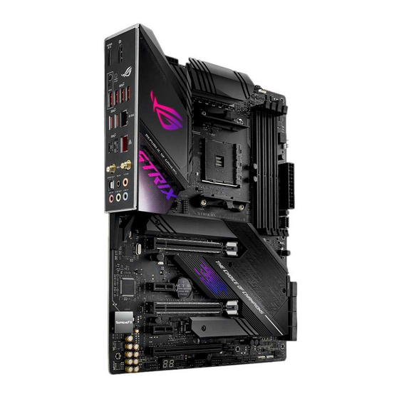
Макет материнской платы

Шаг 3
- Установите модули памяти
- Установщик миннемодулер


Уведомление о заявлении для Австралии
С 1 января 2012 года на всю продукцию ASUS распространяются обновленные гарантии в соответствии с Австралийским законодательством о защите прав потребителей. Для получения последней информации о гарантии на продукт посетите http://www.asus.com/support/. Наши товары поставляются с гарантиями, которые не могут быть исключены в соответствии с Законом Австралии о защите прав потребителей. Вы имеете право на замену или возмещение в случае серьезного сбоя и компенсацию за любые другие разумно предсказуемые убытки или ущерб. Вы также имеете право на ремонт или замену товара, если товар не соответствует приемлемому качеству и неисправность не считается серьезной неисправностью. Если вам нужна помощь, позвоните в службу поддержки клиентов ASUS 1300 2787 88 или посетите нас по адресу http://www.asus.com/support/
Правила обращения с электронными отходами Индии 2016 г.
Этот продукт соответствует «Правилам утилизации электронных отходов Индии, 2016 г.» и запрещает использование свинца, ртути, шестивалентного хрома, полибромированных дифенилов (ПБД) и полибромированных дифениловых эфиров (ПБДЭ) в концентрациях, превышающих 0.1% по весу в однородных материалах. и 0.01% по весу в гомогенных материалах для кадмия, за исключением исключений, перечисленных в Приложении II Правил.
Региональное уведомление для Турции
AEEE Yönetmeliğine Uygundur.
Шаг 4
- Установите устройства хранения. Чтобы установить M.2, обратитесь к руководству пользователя.
- Монтере Ларингсенхетер. Предварительный просмотр для установки на M.2.
Шаг 5
- Установите карты расширения


Шаг 6
- Установите разъем системной панели.
Шаг 7
- Установите разъемы питания ATX


Шаг 8
- Подключите устройства ввода / вывода


Шаг 9
- Включите систему и установите операционную систему и драйверы.


Документы / Ресурсы
Рекомендации

Официальная поддержка | ASUS Global