- Manuals
- Brands
- Gigabyte Manuals
- Motherboard
- GA-H61M-S1
- User manual
-
Contents
-
Table of Contents
-
Bookmarks
Quick Links
GA-H61M-S1
User’s Manual
Rev. 2101
Related Manuals for Gigabyte GA-H61M-S1
Summary of Contents for Gigabyte GA-H61M-S1
-
Page 1
GA-H61M-S1 User’s Manual Rev. 2101… -
Page 3: Identifying Your Motherboard Revision
Copyright © 2012 GIGA-BYTE TECHNOLOGY CO., LTD. All rights reserved. The trademarks mentioned in this manual are legally registered to their respective owners. Disclaimer Information in this manual is protected by copyright laws and is the property of GIGABYTE. Changes to the specifications and features in this manual may be made by GIGABYTE with- out prior notice.
-
Page 4: Table Of Contents
Table of Contents GA-H61M-S1 Motherboard Layout ……………..5 GA-H61M-S1 Motherboard Block Diagram …………..6 Chapter 1 Hardware Installation ………………7 Installation Precautions ………………. 7 Product Specifications ………………8 Installing the CPU ………………10 Installing the Memory ………………11 Installing an Expansion Card …………….11 Back Panel Connectors …………….. 12 Internal Connectors ………………
-
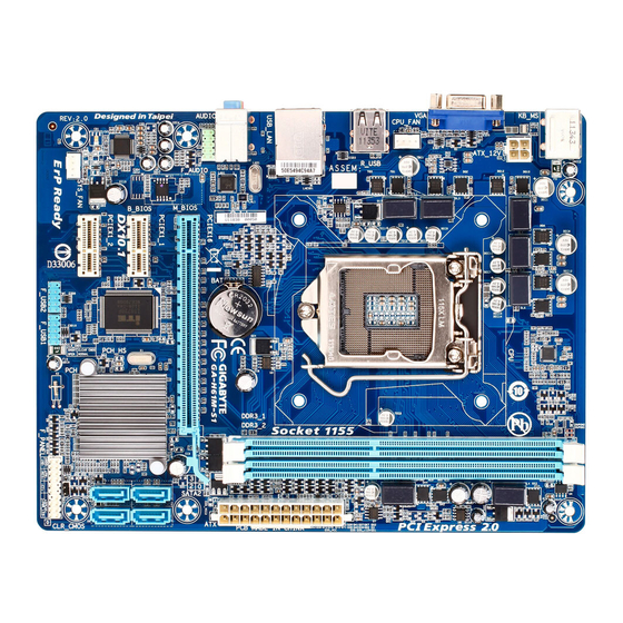
Page 5: Ga-H61M-S1 Motherboard Layout
GA-H61M-S1 Motherboard Layout KB_MS ATX_12V LGA1155 CPU_FAN R_USB USB_LAN GA-H61M-S1 Realtek/Atheros GbE LAN AUDIO PCIEX16 F_AUDIO SATA2 M_BIOS PCIEX1_1 Intel ® PCIEX1_2 CODEC SATA2 F_PANEL F_USB1 SYS_FAN F_USB2 CLR_CMOS Box Contents GA-H61M-S1 motherboard Motherboard driver disk Two SATA cables User’s Manual I/O Shield * The box contents above are for reference only and the actual items shall depend on the product package you obtain.
-
Page 6: Ga-H61M-S1 Motherboard Block Diagram
GA-H61M-S1 Motherboard Block Diagram 1 PCI Express x16 CPU CLK+/- (100 MHz) LGA1155 DDR3 1333/1066/800 MHz PCIe CLK Dual Channel Memory (100 MHz) PCI Express Bus BIOS D-Sub 4 SATA 3Gb/s PCI Express Bus Intel ® 8 USB 2.0/1.1 PCIe CLK…
-
Page 7: Chapter 1 Hardware Installation
Chapter 1 Hardware Installation Installation Precautions The motherboard contains numerous delicate electronic circuits and components which can become damaged as a result of electrostatic discharge (ESD). Prior to installation, carefully read the user’s manual and follow these procedures: Prior to installation, make sure the chassis is suitable for the motherboard. •…
-
Page 8: 1-2 Product Specifications
1-2 Product Specifications Support for Intel Core i7 processors/Intel Core i5 processors/ Š ® ™ ® ™ Intel Core i3 processors/Intel Pentium processors/Intel Celeron processors ® ™ ® ® ® ® in the LGA1155 package (Go to GIGABYTE’s website for the latest CPU support list.) L3 cache varies with CPU Š…
-
Page 9
Back Panel 1 x PS/2 keyboard port Š Connectors 1 x PS/2 mouse port Š 1 x D-Sub port Š 4 x USB 2.0/1.1 ports Š 1 x RJ-45 port Š 3 x audio jacks (Line In/Line Out/Microphone) Š I/O Controller iTE I/O Controller Chip Š… -
Page 10: Installing The Cpu
Installing the CPU Read the following guidelines before you begin to install the CPU: Make sure that the motherboard supports the CPU. • (Go to GIGABYTE’s website for the latest CPU support list.) Always turn off the computer and unplug the power cord from the power outlet before installing •…
-
Page 11: Installing The Memory
Installing the Memory Read the following guidelines before you begin to install the memory: Make sure that the motherboard supports the memory. It is recommended that memory of the • same capacity, brand, speed, and chips be used. (Go to GIGABYTE’s website for the latest supported memory speeds and memory modules.) Always turn off the computer and unplug the power cord from the power outlet before installing •…
-
Page 12: Back Panel Connectors
Back Panel Connectors PS/2 Keyboard and PS/2 Mouse Port Use the upper port (green) to connect a PS/2 mouse and the lower port (purple) to connect a PS/2 keyboard. D-Sub Port The D-Sub port supports a 15-pin D-Sub connector. Connect a monitor that supports D-Sub connection to this port.
-
Page 13: Internal Connectors
Internal Connectors ATX_12V F_PANEL F_AUDIO CPU_FAN F_USB1/2 SYS_FAN CLR_CMOS SATA2 0/1/2/3 Read the following guidelines before connecting external devices: First make sure your devices are compliant with the connectors you wish to connect. • Before installing the devices, be sure to turn off the devices and your computer. Unplug the •…
-
Page 14
1/2) ATX_12V/ATX (2×2 12V Power Connector and 2×12 Main Power Connector) With the use of the power connector, the power supply can supply enough stable power to all the components on the motherboard. Before connecting the power connector, first make sure the power supply is turned off and all devices are properly installed. -
Page 15: Fan Headers
3/4) CPU_FAN/SYS_FAN (Fan Headers) The motherboard has a 4-pin CPU fan header (CPU_FAN), a 4-pin system fan header (SYS_FAN). Most fan headers possess a foolproof insertion design. When connecting a fan cable, be sure to connect it in the correct orientation (the black connector wire is the ground wire). The speed control function requires the use of a fan with fan speed control design.
-
Page 16: Front Panel Heade
6) F_PANEL (Front Panel Header) Connect the power switch, reset switch, speaker, and system status indicator on the chassis to this header according to the pin assignments below. Note the positive and negative pins before connecting the cables. Power Message/Power/ Switch Sleep LED Speaker…
-
Page 17: Front Panel Audio Header
7) F_AUDIO (Front Panel Audio Header) The front panel audio header supports Intel High Definition audio (HD) and AC’97 audio. You may connect your chassis front panel audio module to this header. Make sure the wire assignments of the module con- nector match the pin assignments of the motherboard header.
-
Page 18: Battery
9) CLR_CMOS (Clear CMOS Jumper) Use this jumper to clear the CMOS values (e.g. date information and BIOS configurations) and reset the CMOS values to factory defaults. To clear the CMOS values, use a metal object like a screwdriver to touch the two pins for a few seconds.
-
Page 19: Chapter 2 Bios Setup
Chapter 2 BIOS Setup BIOS (Basic Input and Output System) records hardware parameters of the system in the CMOS on the motherboard. Its major functions include conducting the Power-On Self-Test (POST) during system startup, saving system parameters and loading operating system, etc. BIOS includes a BIOS Setup program that allows the user to modify basic system configuration settings or to activate certain system features.
-
Page 20: Startup Screen
Startup Screen The following startup Logo screen will appear when the computer boots. Function Keys Function Keys: <DEL>: BIOS SETUPQ-FLASH Press the <Delete> key to enter BIOS Setup or to access the Q-Flash utility in BIOS Setup. <F9>: SYSTEM INFORMATION Press the <F9>…
-
Page 21: The Main Menu
The Main Menu On the main menu of the BIOS Setup program, press arrow keys to move among the items and press <Enter> to accept or enter a sub-menu. Or you can use your mouse to select the item you want. (Sample BIOS Version: F4) Setup Menus Enter Q-Flash…
-
Page 22: M.i.t
M.I.T. Whether the system will work stably with the overclock/overvoltage settings you made is dependent on your overall system configurations. Incorrectly doing overclock/overvoltage may result in damage to CPU, chipset, or memory and reduce the useful life of these components. This page is for advanced users only and we recommend you not to alter the default settings to prevent system instability or other unexpected results.
-
Page 23
M.I.T. Current Status This screen provides information on CPU/memory frequencies/parameters. Advanced Frequency Settings CPU Clock Ratio & Allows you to alter the clock ratio for the installed CPU. The adjustable range is dependent on the CPU being installed. CPU Frequency &… -
Page 24
CPU Clock Ratio, CPU Frequency & The settings under the two items above are synchronous to that under the same items on the Advanced Frequency Settings menu. Internal CPU PLL Overvoltage & Enabled allows CPU PLL voltage to operate at a higher value. Disabled allows CPU PLL voltage to operate at default value. -
Page 25
CPU EIST Function (Note 1) & Enables or disables Enhanced Intel SpeedStep Technology (EIST). Depending on CPU loading, Intel EIST technology can dynamically and effectively lower the CPU voltage and core frequency to decrease average power consumption and heat production. Auto lets the BIOS automatically configure this setting. (Default: Auto) Extreme Memory Profile (X.M.P.) &… -
Page 26
Performance Enhance & Allows the system to operate at three different performance levels. Normal Lets the system operate at its basic performance level. Turbo Lets the system operate at its good performance level. (Default) Extreme Lets the system operate at its best performance level. DRAM Timing Selectable &… -
Page 27
Advanced Voltage Settings This sub-menu allows you to set CPU, memory voltage. PC Health Status — 27 -… -
Page 28
Reset Case Open Status & Disabled Keeps or clears the record of previous chassis intrusion status. (Default) Case Open field will show Enabled Clears the record of previous chassis intrusion status and the «No» at next boot. Case Open & Displays the detection status of the chassis intrusion detection device attached to the motherboard CI header. -
Page 29: System
System This section provides information on your motherboard model and BIOS version. You can also select the default language used by the BIOS and manually set the system time. System Language & Selects the default language used by the BIOS. System Date &…
-
Page 30: Bios Features
BIOS Features Boot Option Priorities & Specifies the overall boot order from the available devices. For example, you can set hard drive as the first priority (Boot Option #1) and DVD ROM drive as the second priority (Boot Option #2). The list only displays the device with the highest priority for a specific type.
-
Page 31: Administrator Password
Limit CPUID Maximum (Note) & Allows you to determine whether to limit CPUID maximum value. Set this item to Disabled for Windows XP operating system; set this item to Enabled for legacy operating system such as Windows NT4.0. (Default: Disabled) Execute Disable Bit &…
-
Page 32: Peripherals
Peripherals LAN PXE Boot Option ROM & Allows you to decide whether to activate the boot ROM integrated with the onboard LAN chip. (Default: Disabled) SATA Controller(s) & Enables or disables the integrated SATA controllers. (Default: Enabled) SATA Mode Selection &…
-
Page 33
Internal Graphics Memory Size & Allows you to set the onboard graphics memory size. Options are: 32M~1024M. (Default: 64M) DVMT Total Memory Size & Allows you to allocate the DVMT memory size of the onboard graphics. Options are: 128M, 256M, MAX. (Default: MAX) Legacy USB Support &… -
Page 34: Power Management
Power Management AC BACK & Determines the state of the system after the return of power from an AC power loss. Memory The system returns to its last known awake state upon the return of the AC power. Always Off The system stays off upon the return of the AC power.
-
Page 35: Save & Exit
Note: When using this function, avoid inadequate shutdown from the operating system or removal of the AC power, or the settings may not be effective. & Determines whether to let the system consume less than 1W power in S5 (shutdown) state. (Default: Disabled) Note: When this item is set to Enabled, the following functions will become unavailable: PME event wake up, power on by mouse, power on by keyboard, and wake on LAN.
-
Page 36: Chapter 3 Drivers Installation
Exit Without Saving & Press <Enter> on this item and select Yes. This exits the BIOS Setup without saving the changes made in BIOS Setup to the CMOS. Select No or press <Esc> to return to the BIOS Setup Main Menu. Load Optimized Defaults &…
-
Page 37: Regulatory Statements
Regulatory Statements Regulatory Notices This document must not be copied without our written permission, and the contents there of must not be imparted to a third party nor be used for any unauthorized purpose. Contravention will be prosecuted. We believe that the information contained herein was accurate in all respects at the time of printing.
-
Page 38
— 38 -… -
Page 39
— 39 -… -
Page 40
Contact Us GIGA-BYTE TECHNOLOGY CO., LTD. Address: No.6, Bao Chiang Road, Hsin-Tien Dist., New Taipei City 231,Taiwan TEL: +886-2-8912-4000, FAX: +886-2-8912-4003 Tech. and Non-Tech. Support (Sales/Marketing) : http://ggts.gigabyte.com.tw WEB address (English): http://www.gigabyte.com WEB address (Chinese): http://www.gigabyte.tw You may go to the GIGABYTE website, select your language in the language list on the top right corner of the website. GIGABYTE Global Service System •…
-
Драйверы
31
-
Инструкции по эксплуатации
7
Языки:

Gigabyte GA-H61M-S1 инструкция по эксплуатации
(72 страницы)
- Языки:Венгерский, Греческий, Испанский, Итальянский, Немецкий, Польский, Португальский, Русский, Турецкий, Французский, Чешский
-
Тип:
PDF -
Размер:
18.6 MB -
Описание:
Installation Guidebook


На NoDevice можно скачать инструкцию по эксплуатации для Gigabyte GA-H61M-S1. Руководство пользователя необходимо для ознакомления с правилами установки и эксплуатации Gigabyte GA-H61M-S1. Инструкции по использованию помогут правильно настроить Gigabyte GA-H61M-S1, исправить ошибки и выявить неполадки.
- Manuals
- Brands
- Gigabyte Manuals
- Motherboard
- GA-H61M-S1
- User manual
Manual
-
Contents
-
Table of Contents
-
Bookmarks
Quick Links
GA-H61M-S1
User’s Manual
Rev. 2001
Related Manuals for Gigabyte GA-H61M-S1
Summary of Contents for Gigabyte GA-H61M-S1
-
Page 1
GA-H61M-S1 User’s Manual Rev. 2001… -
Page 3: Identifying Your Motherboard Revision
The trademarks mentioned in this manual are legally registered to their respective owners. Disclaimer Information in this manual is protected by copyright laws and is the property of GIGABYTE. Changes to the specifications and features in this manual may be made by GIGABYTE with- out prior notice.
-
Page 4: Table Of Contents
Table of Contents GA-H61M-S1 Motherboard Layout ……………..5 GA-H61M-S1 Motherboard Block Diagram …………..6 Chapter 1 Hardware Installation ………………7 Installation Precautions ………………. 7 Product Specifications ………………8 Installing the CPU ………………10 Installing the Memory ………………11 Installing an Expansion Card …………….11 Back Panel Connectors …………….. 12 Internal Connectors ………………
-
Page 5: Ga-H61M-S1 Motherboard Layout
GA-H61M-S1 Motherboard Layout KB_MS ATX_12V LGA1155 CPU_FAN R_USB USB_LAN GA-H61M-S1 Realtek RTL8111F AUDIO PCIEX16 F_AUDIO SATA2 M_BIOS PCIEX1_1 Intel ® IT8728 PCIEX1_2 CODEC F_USB1 CLR_CMOS SYS_FAN F_USB2 F_PANEL Box Contents GA-H61M-S1 motherboard Motherboard driver disk Two SATA cables User’s Manual I/O Shield * The box contents above are for reference only and the actual items shall depend on the product package you obtain.
-
Page 6: Ga-H61M-S1 Motherboard Block Diagram
GA-H61M-S1 Motherboard Block Diagram 1 PCI Express x16 CPU CLK+/- (100 MHz) LGA1155 DDR3 1333/1066/800 MHz PCIe CLK Dual Channel Memory (100 MHz) PCI Express Bus BIOS D-Sub 4 SATA 3Gb/s PCI Express Bus Intel ® 8 USB 2.0/1.1 PCIe CLK…
-
Page 7: Chapter 1 Hardware Installation
Chapter 1 Hardware Installation Installation Precautions The motherboard contains numerous delicate electronic circuits and components which can become damaged as a result of electrostatic discharge (ESD). Prior to installation, carefully read the user’s manual and follow these procedures: Prior to installation, make sure the chassis is suitable for the motherboard. •…
-
Page 8: 1-2 Product Specifications
Dual channel memory architecture Š Support for DDR3 1333/1066/800 MHz memory modules Š Support for non-ECC memory modules Š (Go to GIGABYTE’s website for the latest supported memory speeds and memory modules.) Onboard Integrated Graphics Prosessor: Š Graphics 1 x D-Sub port…
-
Page 9
Support for Microsoft Windows 7/Vista/XP Š ® System Form Factor Micro ATX Form Factor; 22.6cm x 17.4cm Š * GIGABYTE reserves the right to make any changes to the product specifications and product-related information without prior notice. — 9 -… -
Page 10: Installing The Cpu
Read the following guidelines before you begin to install the CPU: Make sure that the motherboard supports the CPU. • (Go to GIGABYTE’s website for the latest CPU support list.) Always turn off the computer and unplug the power cord from the power outlet before installing •…
-
Page 11: Installing The Memory
Make sure that the motherboard supports the memory. It is recommended that memory of the • same capacity, brand, speed, and chips be used. (Go to GIGABYTE’s website for the latest supported memory speeds and memory modules.) Always turn off the computer and unplug the power cord from the power outlet before installing •…
-
Page 12: Back Panel Connectors
Back Panel Connectors PS/2 Keyboard and PS/2 Mouse Port Use the upper port (green) to connect a PS/2 mouse and the lower port (purple) to connect a PS/2 keyboard. D-Sub Port The D-Sub port supports a 15-pin D-Sub connector. Connect a monitor that supports D-Sub connection to this port.
-
Page 13: Internal Connectors
Internal Connectors ATX_12V F_PANEL F_AUDIO CPU_FAN F_USB1/2 SYS_FAN CLR_CMOS SATA2 0/1/2/3 Read the following guidelines before connecting external devices: First make sure your devices are compliant with the connectors you wish to connect. • Before installing the devices, be sure to turn off the devices and your computer. Unplug the •…
-
Page 14
1/2) ATX_12V/ATX (2×2 12V Power Connector and 2×12 Main Power Connector) With the use of the power connector, the power supply can supply enough stable power to all the components on the motherboard. Before connecting the power connector, first make sure the power supply is turned off and all devices are properly installed. -
Page 15: Fan Headers
3/4) CPU_FAN/SYS_FAN (Fan Headers) The motherboard has a 4-pin CPU fan header (CPU_FAN), a 4-pin system fan header (SYS_FAN). Most fan headers possess a foolproof insertion design. When connecting a fan cable, be sure to connect it in the correct orientation (the black connector wire is the ground wire). The speed control function requires the use of a fan with fan speed control design.
-
Page 16: Front Panel Header
6) F_PANEL (Front Panel Header) Connect the power switch, reset switch, speaker, and system status indicator on the chassis to this header according to the pin assignments below. Note the positive and negative pins before connecting the cables. Power Message/Power/ Switch Sleep LED Speaker…
-
Page 17: Front Panel Audio Header
7) F_AUDIO (Front Panel Audio Header) The front panel audio header supports Intel High Definition audio (HD) and AC’97 audio. You may connect your chassis front panel audio module to this header. Make sure the wire assignments of the module con- nector match the pin assignments of the motherboard header.
-
Page 18: Battery
9) CLR_CMOS (Clear CMOS Jumper) Use this jumper to clear the CMOS values (e.g. date information and BIOS configurations) and reset the CMOS values to factory defaults. To clear the CMOS values, use a metal object like a screwdriver to touch the two pins for a few seconds.
-
Page 19: Chapter 2 Bios Setup
To access the BIOS Setup program, press the <Delete> key during the POST when the power is turned on. To upgrade the BIOS, use either the GIGABYTE Q-Flash or @BIOS utility. Q-Flash allows the user to quickly and easily upgrade or back up BIOS without entering the operating •…
-
Page 20: The Main Menu
The Main Menu On the main menu of the BIOS Setup program, press arrow keys to move among the items and press <Enter> to accept or enter a sub-menu. Or you can use your mouse to select the item you want. (Sample BIOS Version: F1b) Setup Menus Enter Q-Flash…
-
Page 21: M.i.t
M.I.T. Whether the system will work stably with the overclock/overvoltage settings you made is dependent on your overall system configurations. Incorrectly doing overclock/overvoltage may result in damage to CPU, chipset, or memory and reduce the useful life of these components. This page is for advanced users only and we recommend you not to alter the default settings to prevent system instability or other unexpected results.
-
Page 22
M.I.T. Current Status This screen provides information on CPU/memory frequencies/parameters. Advanced Frequency Settings CPU Clock Ratio & Allows you to alter the clock ratio for the installed CPU. The adjustable range is dependent on the CPU being installed. CPU Frequency &… -
Page 23
CPU Clock Ratio, CPU Frequency & The settings under the two items above are synchronous to that under the same items on the Advanced Frequency Settings menu. Internal CPU PLL Overvoltage & Enabled allows CPU PLL voltage to operate at a higher value. Disabled allows CPU PLL voltage to operate at default value. -
Page 24
CPU EIST Function (Note) & Enables or disables Enhanced Intel SpeedStep Technology (EIST). Depending on CPU loading, Intel EIST technology can dynamically and effectively lower the CPU voltage and core frequency to decrease average power consumption and heat production. Auto lets the BIOS automatically configure this setting. (Default: Auto) Bi-Directional PROCHOT (Note) -
Page 25: Dram Timing Selectable
System Memory Multiplier, Memory Frequency(Mhz) & The settings under the two items above are synchronous to those under the same items on the Advanced Frequency Settings menu. Performance Enhance & Allows the system to operate at three different performance levels. Normal Lets the system operate at its basic performance level.
-
Page 26
Advanced Voltage Settings CPU Vtt & Allows you to set CPU Vtt voltage. The default is Auto. DRAM Voltage & Allows you to set memory voltage. The default is Auto. PC Health Status — 26 -… -
Page 27
Reset Case Open Status & Disabled Keeps or clears the record of previous chassis intrusion status. (Default) Case Opened field will show Enabled Clears the record of previous chassis intrusion status and the «No» at next boot. Case Opened & Displays the detection status of the chassis intrusion detection device attached to the motherboard CI header. -
Page 28: System
Miscellaneous Settings Isochronous Support & Determines whether to enable specific streams within the CPU and Chipset. This item is present only when you install a CPU that supports this feature. For more information about Intel CPUs’ unique features, please visit Intel’s website. (Default: Enabled) System This section provides information on your motherboard model and BIOS version.
-
Page 29: Bios Features
System Language & Selects the default language used by the BIOS. System Date & Sets the system date. The date format is week (read-only), month, date, and year. Use <Enter> to switch between the Month, Date, and Year fields and use the up arrow or down arrow key to set the desired value.
-
Page 30: Bootup Numlock State
Or if you want to install an operating system that supports GPT partitioning such as Windows 7 64-bit, select the optical drive that contains the Windows 7 64-bit installation disk and is prefixed with «UEFI:» string. Hard Drive/CD/DVD ROM Drive/Floppy Drive/Network Device BBS Priorities &…
-
Page 31: Peripherals
Peripherals LAN PXE Boot Option ROM & Allows you to decide whether to activate the boot ROM integrated with the onboard LAN chip. (Default: Disabled) SATA Controller(s) (Intel H61 Chipset) & Enables or disables the integrated SATA controllers. (Default: Enabled) SATA Mode Selection (Intel H61 Chipset) &…
-
Page 32
Internal Graphics Memory Size & Allows you to set the onboard graphics memory size. Options are: 32M~1024M. (Default: 64M) DVMT Total Memory Size & Allows you to allocate the DVMT memory size of the onboard graphics. Options are: 128M, 256M, MAX. (Default: MAX) Legacy USB Support &… -
Page 33: Power Management
Power Management AC BACK & Determines the state of the system after the return of power from an AC power loss. Memory The system returns to its last known awake state upon the return of the AC power. Always Off The system stays off upon the return of the AC power.
-
Page 34: Save & Exit
Note: When using this function, avoid inadequate shutdown from the operating system or removal of the AC power, or the settings may not be effective. & Determines whether to let the system consume less than 1W power in S5 (shutdown) state. (Default: Disabled) Note: When this item is set to Enabled, the following functions will become unavailable: PME event wake up, power on by mouse, power on by keyboard, and wake on LAN.
-
Page 35: Chapter 3 Drivers Installation
Exit Without Saving & Press <Enter> on this item and select Yes. This exits the BIOS Setup without saving the changes made in BIOS Setup to the CMOS. Select No or press <Esc> to return to the BIOS Setup Main Menu. Load Optimized Defaults &…
-
Page 36: Regulatory Statements
«end of life» product. Restriction of Hazardous Substances (RoHS) Directive Statement GIGABYTE products have not intended to add and safe from hazardous substances (Cd, Pb, Hg, Cr+6, PBDE and PBB). The parts and components have been carefully selected to meet RoHS requirement. Moreover, we at GIGABYTE are continuing our efforts to develop products that do not use internationally banned toxic chemicals.
-
Page 37
— 37 -… -
Page 38
— 38 -… -
Page 39
— 39 -… -
Page 40
Tech. and Non-Tech. Support (Sales/Marketing) : http://ggts.gigabyte.com.tw WEB address (English): http://www.gigabyte.com WEB address (Chinese): http://www.gigabyte.tw You may go to the GIGABYTE website, select your language in the language list on the top right corner of the website. GIGABYTE Global Service System •…
Посмотреть инструкция для Gigabyte GA-H61M-S1 бесплатно. Руководство относится к категории Материнские платы, 1 человек(а) дали ему среднюю оценку 7.5. Руководство доступно на следующих языках: английский. У вас есть вопрос о Gigabyte GA-H61M-S1 или вам нужна помощь? Задайте свой вопрос здесь
Не можете найти ответ на свой вопрос в руководстве? Вы можете найти ответ на свой вопрос ниже, в разделе часто задаваемых вопросов о Gigabyte GA-H61M-S1.
Какая ширина Gigabyte GA-H61M-S1?
Какая толщина Gigabyte GA-H61M-S1?
Инструкция Gigabyte GA-H61M-S1 доступно в русский?
Не нашли свой вопрос? Задайте свой вопрос здесь
GIGABYTE
GA-H61M-S1 (rev. 2.2) Инструкция по применению
Популярность:
7565 просмотры
Подсчет страниц:
40 страницы
Тип файла:
Размер файла:
12.15 Mb