-
Contents
-
Table of Contents
-
Bookmarks
Quick Links
Intel® Desktop Board D945GCPE
Product Guide
Order Number: D98018-001
Related Manuals for Intel D945GCPE — Desktop Board Motherboard
Summary of Contents for Intel D945GCPE — Desktop Board Motherboard
-
Page 1
Intel® Desktop Board D945GCPE Product Guide Order Number: D98018-001… -
Page 2: Revision History
WARRANTIES RELATING TO FITNESS FOR A PARTICULAR PURPOSE, MERCHANTABILITY, OR INFRINGEMENT OF ANY PATENT, COPYRIGHT OR OTHER INTELLECTUAL PROPERTY RIGHT. Intel products are not intended for use in medical, life saving, or life sustaining applications. Intel may make changes to specifications and product descriptions at any time, without notice.
-
Page 3: Intended Audience
The suitability of this product for other PC or embedded non-PC applications or other environments, such as medical, industrial, alarm systems, test equipment, etc., may not be supported without further evaluation by Intel. Document Organization The chapters in this Product Guide are arranged as follows:…
-
Page 4: Box Contents
Intel Desktop Board D945GCPE Product Guide Terminology The table below gives descriptions of some common terms used in the product guide. Term Description Gigabyte (1,073,741,824 bytes) Gigahertz (one billion hertz) Kilobyte (1024 bytes) Megabyte (1,048,576 bytes) Mbit Megabit (1,048,576 bits)
-
Page 5: Table Of Contents
Contents 1 Desktop Board Features Supported Operating Systems…………….10 Desktop Board Components……………..11 Processor………………….13 Main Memory…………………13 ® Intel 945GC Express Chipset …………….14 Onboard Audio Subsystem ………………14 Input/Output (I/O) Controller …………….15 LAN Subsystem ………………..15 LAN Subsystem Software…………….15 RJ-45 LAN Connector LEDs…………….16 Hi-Speed USB 2.0 Support ………………16 Enhanced IDE Interface ………………17…
-
Page 6
Intel Desktop Board D945GCPE Product Guide Connecting the Processor Fan Heat Sink Cable……….31 Removing the Processor …………….31 Installing and Removing Memory…………….32 Installing DIMMs ………………34 Removing DIMMs………………35 Connecting the Diskette Drive Cable …………..36 Connecting the IDE Cable………………37 Connecting the Serial ATA (SATA) Cable…………..38 Connecting to Internal Headers …………….39… -
Page 7
1. Feature Summary………………9 2. Desktop Board D945GCPE Components …………12 3. LAN Connector LED States …………….16 4. Front Panel Audio Header Signal Names for Intel High Definition Audio….40 5. AC ’97 Audio Header Signal Names …………..40 6. Serial Port Header Signal Names…………..41 7. -
Page 8
Intel Desktop Board D945GCPE Product Guide viii… -
Page 9: Desktop Board Features
1 Desktop Board Features ® This chapter briefly describes the main features of Intel Desktop Board D945GCPE. Table 1 summarizes the major features of the desktop board. Table 1. Feature Summary microATX (218.44 millimeters [8.60 inches] x 243.84 millimeters Form Factor [9.60 inches])
-
Page 10: Supported Operating Systems
Intel Desktop Board D945GCPE Product Guide Table 1. Feature Summary (continued) LAN Support 10/100 Mb/s LAN subsystem using a Realtek RTL8101E-GR Gigabit Ethernet Controller Power • Support for Advanced Configuration and Power Interface (ACPI) Management • Suspend to RAM (STR) •…
-
Page 11: Desktop Board Components
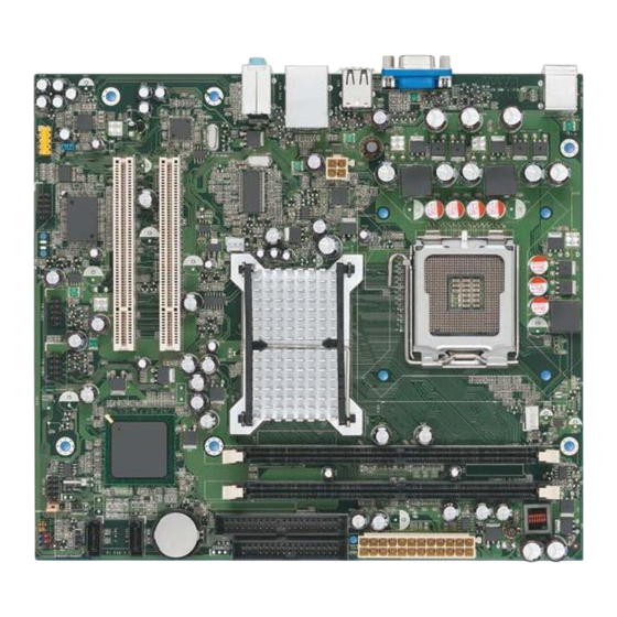
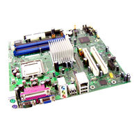
Desktop Board Features Desktop Board Components Figure 1 shows the approximate location of the major components on Desktop Board D945GCPE. Figure 1. Desktop Board D945GCPE Components…
-
Page 12: Desktop Board D945Gcpe Components
Intel Desktop Board D945GCPE Product Guide Table 2. Desktop Board D945GCPE Components Label Description Front panel audio header PCI bus connector 2 PCI bus connector 1 Rear chassis fan header (3-pin) Back panel connectors 12 V processor core voltage connector (2 x 2 pin)
-
Page 13: Processor
Desktop Board D945GCPE supports an Intel processor in the LGA775 package. Processors are not included with the desktop board and must be purchased separately.
-
Page 14: Intel 945Gc Express Chipset
Intel Graphics Media Accelerator 950 (Intel GMA 950). The ICH7 is a centralized controller for the board’s I/O paths. Related Link: Go to the following link for more information about the Intel 945GC Express Chipset: http://www.intel.com/products/desktop/chipsets/index.htm?iid=chips_body+desk Onboard Audio Subsystem Desktop Board D945GCPE has a 4-channel (2 + 2) onboard audio subsystem that includes a Realtek ALC662 audio codec.
-
Page 15: Input/Output (I/O) Controller
• Realtek RTL8101E-GR Ethernet Controller device for 10/100 Mb/s Ethernet LAN connectivity • RJ-45 connector with status indicator LEDs LAN Subsystem Software For LAN software and drivers, refer to the D945GCPE link on Intel’s World Wide Web site at: http://support.intel.com/support/motherboards/desktop…
-
Page 16: Rj-45 Lan Connector Leds
Intel Desktop Board D945GCPE Product Guide RJ-45 LAN Connector LEDs Two LEDs are built into the RJ-45 LAN connector located on the back panel (see Figure 2). These LEDs indicate the status of the LAN. Figure 2. LAN Connector LEDs Table 3 describes the LED states when the board is powered up and the LAN subsystem is operating.
-
Page 17: Enhanced Ide Interface
Desktop Board Features Enhanced IDE Interface The desktop board’s IDE interface handles the exchange of information between the processor and peripheral devices such as hard disk drives and CD-ROM drives. The interface supports: • Up to two IDE devices (such as hard drives) •…
-
Page 18: Pci* Auto Configuration
Intel Desktop Board D945GCPE Product Guide PCI* Auto Configuration If you install a PCI add-in card in your computer, the PCI auto-configuration utility in the BIOS automatically detects and configures the resources (IRQs, DMA channels, and I/O space) for that add-in card. You do not need to run the BIOS Setup program after you install a PCI add-in card.
-
Page 19: Chassis Intrusion Detection
Desktop Board Features Chassis Intrusion Detection The board supports a chassis security feature that detects if the chassis cover has been removed. The security feature uses a mechanical switch on the chassis that can be connected to the chassis intrusion header on the desktop board. See Figure 1, S on page 11 for the location of the chassis intrusion header.
-
Page 20: Fan Headers
Intel Desktop Board D945GCPE Product Guide Fan Headers The function/operation of the fans is as follows: • The fans are on when the computer is in the ACPI S0 or S1 state. • The fans are off when the computer is in the ACPI S3, S4, or S5 state.
-
Page 21: +5 V Standby Power Indicator
Figure 3. Standby Power Indicator Related Links: For more information on standby current requirements for the desktop board, refer to the Technical Product Specification by going to the following link, finding the product, and selecting Product Documentation from the left-hand menu: http://support.intel.com/support/motherboards/desktop/…
-
Page 22: Wake From Usb
ENERGY STAR* Capable In 2007, the US Department of Energy and the US Environmental Protection Agency revised the ENERGY STAR requirements. Intel worked directly with these two governmental agencies to define the new requirements. Currently Intel Desktop Boards are capable of meeting the new ENERGY STAR requirements depending on system configuration.
-
Page 23: Installing And Replacing Desktop Board Components
2 Installing and Replacing Desktop Board Components This chapter tells you how to: • Install the I/O shield • Install and remove the desktop board • Install and remove a processor • Install and remove memory • Connect the diskette drive cable •…
-
Page 24: Installation Precautions
Intel Desktop Board D945GCPE Product Guide Installation Precautions When you install and test the Intel desktop board, observe all warnings and cautions in the installation instructions. To avoid injury, be careful of: • Sharp pins on connectors • Sharp pins on printed circuit assemblies •…
-
Page 25: Installing The I/O Shield
Installing and Replacing Desktop Board Components Installing the I/O Shield The desktop board comes with an I/O shield. When installed in the chassis, the shield blocks radio frequency transmissions, protects internal components from dust and foreign objects, and promotes correct airflow within the chassis. Install the I/O shield before installing the desktop board in the chassis.
-
Page 26: Installing And Removing The Desktop Board
Intel Desktop Board D945GCPE Product Guide Installing and Removing the Desktop Board CAUTION Only qualified technical personnel should do this procedure. Disconnect the computer from its power source before performing the procedures described here. Failure to disconnect the power before you open the computer can result in personal injury or equipment damage.
-
Page 27: Installing And Removing A Processor
Installing and Replacing Desktop Board Components Installing and Removing a Processor Instructions on how to install the processor on the desktop board are given below. Installing a Processor CAUTION Before installing or removing the processor, make sure the AC power has been removed by unplugging the power cord from the computer;…
-
Page 28: Lift The Load Plate
Intel Desktop Board D945GCPE Product Guide 3. Lift the load plate (Figure 7, A). Do not touch the socket contacts (Figure 7, B). Figure 7. Lift the Load Plate 4. Remove the plastic protective socket cover from the load plate (see Figure 8). Do not discard the protective socket cover.
-
Page 29: Remove The Processor From The Protective Processor Cover
Installing and Replacing Desktop Board Components 5. Remove the processor from the protective processor cover. Hold the processor only at the edges, being careful not to touch the bottom of the processor (see Figure 9). Do not discard the protective processor cover. Always replace the processor cover if the processor is removed from the socket.
-
Page 30: Installing The Processor Fan Heat Sink
Intel Desktop Board D945GCPE Product Guide 7. Pressing down on the load plate (Figure 11, A) close and engage the socket lever (Figure 11, B). Figure 11. Close the Load Plate Installing the Processor Fan Heat Sink Desktop Board D945GCPE has an integrated processor fan heat sink retention mechanism (RM).
-
Page 31: Connecting The Processor Fan Heat Sink Cable
Processor Fan Header Removing the Processor For instructions on how to remove the processor fan heat sink and processor, refer to the processor installation manual or the Intel World Wide Web site at: Integration of the Boxed Intel Pentium 4 Processor in the 775-Land Package ®…
-
Page 32: Installing And Removing Memory
Intel Desktop Board D945GCPE Product Guide Installing and Removing Memory NOTE To be fully compliant with all applicable Intel SDRAM memory specifications, the board requires DIMMs that support the Serial Presence Detect (SPD) data structure. You can access the PC Serial Presence Detect Specification at: http://www.intel.com/technology/memory/ddr/specs/dda18c32_64_128x72ag_a.pdf…
-
Page 33: Use Ddr2 Dimms
Installing and Replacing Desktop Board Components To make sure you have the correct DIMM, place it on the illustration of the DDR2 DIMM in Figure 14. All the notches should match with the DDR2 DIMM. Figure 14. Use DDR2 DIMMs…
-
Page 34: Installing Dimms
Intel Desktop Board D945GCPE Product Guide Installing DIMMs To install a DIMM, follow these steps: 1. Observe the precautions in «Before You Begin» on page 23. 2. Turn off all peripheral devices connected to the computer. Turn off the computer and disconnect the AC power cord.
-
Page 35: Removing Dimms
Installing and Replacing Desktop Board Components Removing DIMMs To remove a DIMM, follow these steps: 1. Observe the precautions in «Before You Begin» on page 23. 2. Turn off all peripheral devices connected to the computer. Turn off the computer. 3.
-
Page 36: Connecting The Diskette Drive Cable
• Observe the precautions in «Before You Begin» on page 23. • Attach the cable end labeled P1 to the diskette drive connector on the Intel Desktop Board (Figure 16, A). • Attach the cable end labeled P2 to the diskette drive (Figure 16, B).
-
Page 37: Connecting The Ide Cable
• Observe the precautions in «Before You Begin» on page 23. • Attach the cable end with the single connector (blue) to the Intel desktop board (Figure 17, A). • Attach the cable end with the two closely spaced connectors (gray and black) to the drives (Figure 17, B).
-
Page 38: Connecting The Serial Ata (Sata) Cable
Intel Desktop Board D945GCPE Product Guide Connecting the Serial ATA (SATA) Cable The SATA cable supports the Serial ATA protocol and connects a single drive to the desktop board. For correct cable function: 1. Observe the precautions in «Before You Begin» on page 23.
-
Page 39: Connecting To Internal Headers
Installing and Replacing Desktop Board Components Connecting to Internal Headers Before connecting cables to the internal headers, observe the precautions in «Before You Begin» on page 23. Figure 19 shows the location of the internal headers. Item Description Front panel audio Serial port Chassis intrusion Alternate front panel power LED…
-
Page 40: Connecting To The Front Panel Audio Header
Figure 19, A on page 39 shows the location of the front panel audio header. Table 4 shows the pin assignments for the front panel audio header. Table 4. Front Panel Audio Header Signal Names for Intel High Definition Audio…
-
Page 41: Connecting To The Serial Port Header
Installing and Replacing Desktop Board Components To restore back panel audio, follow these steps: 1. Observe the precautions in «Before You Begin» on page 23. 2. Turn off all peripheral devices connected to the computer. Turn off the computer and disconnect the AC power cord. 3.
-
Page 42: Connecting To The Front Panel Header
Intel Desktop Board D945GCPE Product Guide Connecting to the Front Panel Header Before connecting to the front panel header, observe the precautions in «Before You Begin» on page 23. See Figure 19, E on page 39 for the location of the front panel header.
-
Page 43: Connecting To The Usb 2.0 Headers
Installing and Replacing Desktop Board Components Connecting to the USB 2.0 Headers Before connecting to the USB 2.0 headers, observe the precautions in «Before You Begin» on page 23. See Figure 19, F on page 39 for the location of the USB 2.0 headers.
-
Page 44: Connecting Chassis Fan And Power Cables
Intel Desktop Board D945GCPE Product Guide Connecting Chassis Fan and Power Cables Connecting a Chassis Fan Cable Connect the chassis fan cable to the chassis fan header on the desktop board. Figure 21 shows the location of the chassis fan header.
-
Page 45: Connecting Power Cables
Installing and Replacing Desktop Board Components Connecting Power Cables CAUTION Failure to use the appropriate power supply and/or not connecting the 12 V (2 x 2 pin) power connector to the desktop board may result in damage to the board or the system may not function properly.
-
Page 46: Setting The Bios Configuration Jumper
Intel Desktop Board D945GCPE Product Guide Setting the BIOS Configuration Jumper NOTE Always turn off the power and unplug the power cord from the computer before moving the jumper. Moving the jumper with the power on may result in unreliable computer operation.
-
Page 47: Clearing Passwords
Installing and Replacing Desktop Board Components The three-pin BIOS jumper block enables all board configuration to be done in the BIOS Setup program. Table 11 shows the jumper settings for the BIOS Setup program modes. Table 11. Jumper Settings for the BIOS Setup Program Modes Jumper Setting Mode…
-
Page 48: Replacing The Battery
Intel Desktop Board D945GCPE Product Guide 8. Use the arrow keys to select Clear Passwords. Press <Enter> and Setup displays a pop-up screen requesting that you confirm clearing the password. Select Yes and press <Enter>. Setup displays the maintenance menu again.
-
Page 49
Installing and Replacing Desktop Board Components VIKTIGT! Risk för explosion om batteriet ersätts med felaktig batterityp. Batterier ska kasseras enligt de lokala miljövårdsbestämmelserna. VARO Räjähdysvaara, jos pariston tyyppi on väärä. Paristot on kierrätettävä, jos se on mahdollista. Käytetyt paristot on hävitettävä paikallisten ympäristömääräysten mukaisesti. -
Page 50
Intel Desktop Board D945GCPE Product Guide Προσοχή Υπάρχει κίνδυνος για έκρηξη σε περίπτωση που η μπαταρία αντικατασταθεί από μία λανθασμένου τύπου. Οι μπαταρίες θα πρέπει να ανακυκλώνονται όταν κάτι τέτοιο είναι δυνατό. Η απόρριψη των χρησιμοποιημένων μπαταριών πρέπει να γίνεται σύμφωνα με… -
Page 51
Installing and Replacing Desktop Board Components POZOR Zamenjava baterije z baterijo drugačnega tipa lahko povzroči eksplozijo. Če je mogoče, baterije reciklirajte. Rabljene baterije zavrzite v skladu z lokalnimi okoljevarstvenimi predpisi. UYARI Yanlış türde pil takıldığında patlama riski vardır. Piller mümkün olduğunda geri dönüştürülmelidir. -
Page 52
Intel Desktop Board D945GCPE Product Guide To replace the battery, follow these steps: 1. Observe the precautions in «Before You Begin» (see page 23). 2. Turn off all peripheral devices connected to the computer. Disconnect the computer’s power cord from the AC power source (wall outlet or power adapter). -
Page 53: Updating The Bios
Updating the BIOS with the Intel Express BIOS Update Utility With the Intel Express BIOS Update utility you can update the system BIOS while in the Windows environment. The BIOS file is included in an automated update utility ® that combines the functionality of the Intel Flash Memory Update Utility and the ease-of use of Windows-based installation wizards.
-
Page 54: Obtaining The Bios Update File
Intel Flash Memory Update Utility You can obtain the BIOS update file through your computer supplier or by navigating to the Desktop Board D945GCPE page on the Intel World Wide Web site at: http://support.intel.com/support/motherboards/desktop Navigate to the D945GCPE page, click “[view] Latest BIOS updates,” and select the Iflash BIOS Update utility file.
-
Page 55: A Error Messages
A Error Messages Desktop Board D945GCPE reports POST errors by displaying an error message on the monitor. BIOS Error Messages When a recoverable error occurs during the POST, the BIOS displays an error message describing the problem. Table 12 gives an explanation of the BIOS error messages. Table 12.
-
Page 56
Intel Desktop Board D945GCPE Product Guide… -
Page 57: B Regulatory Compliance
B Regulatory Compliance This appendix contains the following regulatory compliance information for Desktop Board D945GCPE: • Safety standards • European Union Declaration of Conformity statement • Product Ecology statements • Electromagnetic Compatibility (EMC) regulations • Product certifications Safety Standards Desktop Board D945GCPE complies with the safety standards stated in Table 13 when correctly installed in a compatible host system.
-
Page 58: European Union Declaration Of Conformity Statement
Intel Desktop Board D945GCPE Product Guide European Union Declaration of Conformity Statement We, Intel Corporation, declare under our sole responsibility that the product Intel ® Desktop Board D945GCPE is in conformity with all applicable essential requirements necessary for CE marking, following the provisions of the European Council Directives 2004/108/EC (EMC Directive) and 2006/95/EC (Low Voltage Directive).
-
Page 59: Product Ecology Statements
The following information is provided to address worldwide product ecology concerns and regulations. Recycling Considerations As part of its commitment to environmental responsibility, Intel has implemented the Intel Product Recycling Program to allow retail consumers of Intel’s branded products ®…
-
Page 60
Français Dans le cadre de son engagement pour la protection de l’environnement, Intel a mis en œuvre le programme Intel Product Recycling Program (Programme de recyclage des produits Intel) pour permettre aux consommateurs de produits Intel de recycler les produits usés en les retournant à… -
Page 61: Lead-Free Desktop Board
Regulatory Compliance Portuguese Como parte deste compromisso com o respeito ao ambiente, a Intel implementou o Programa de Reciclagem de Produtos para que os consumidores finais possam enviar produtos Intel usados para locais selecionados, onde esses produtos são reciclados de maneira adequada.
-
Page 62
Intel Desktop Board D945GCPE Product Guide Table 14. Lead-Free Board Markings Description Mark Lead-Free 2 Level Interconnect: This symbol is used to identify electrical and electronic assemblies and components in which the lead (Pb) concentration level in the Intel Desktop Board substrate… -
Page 63: Emc Regulations
Regulatory Compliance EMC Regulations Desktop Board D945GCPE complies with the EMC regulations stated in Table 15 when correctly installed in a compatible host system. Table 15. EMC Regulations Regulation Title FCC 47 CFR Part 15, Title 47 of the Code of Federal Regulations, Part 15, Subpart B, Subpart B Radio Frequency Devices.
-
Page 64: Ensure Electromagnetic Compatibility (Emc) Compliance
Intel Desktop Board D945GCPE Product Guide Korean Class B statement translation: This is household equipment that is certified to comply with EMC requirements. You may use this equipment in residential environments and other non-residential environments. Ensure Electromagnetic Compatibility (EMC) Compliance…
-
Page 65: Product Certifications
Description Mark UL joint US/Canada Recognized Component mark. Includes adjacent UL file number for Intel Desktop Boards: E210882. FCC Declaration of Conformity logo mark for Class B equipment. Includes Intel name and D945GCPE model designation. CE mark. Declaring compliance to European Union (EU) EMC directive and Low Voltage directive.
-
Page 66: Chassis And Component Certifications
Intel Desktop Board D945GCPE Product Guide Chassis and Component Certifications Ensure that the chassis and certain components; such as the power supply, peripheral drives, wiring, and cables; are components certified for the country or market where used. Agency certification marks on the product are proof of certification. Typical…
- Manuals
- Brands
- Intel Manuals
- Motherboard
- D915GLVG
Manuals and User Guides for Intel D915GLVG. We have 4 Intel D915GLVG manuals available for free PDF download: Specification, Product Manual
Intel D915GLVG Specification (84 pages)
Desktop Board
Brand: Intel
|
Category: Motherboard
|
Size: 1.67 MB
Table of Contents
-
Revision History
2
-
Intended Audience
3
-
What this Document Contains
3
-
Table of Contents
5
-
Tables
10
-
1 Product Description
10
-
Overview
10
-
Feature Summary
10
-
-
-
Product Description
11
-
Board Components
12
-
Board Components Shown in Figure 1
13
-
Block Diagram
14
-
-
Board Layout
12
-
Figures
12
-
Online Support
15
-
Processor
15
-
Supported System Bus Frequency and Memory Speed Combinations
16
-
System Memory
16
-
Supported Memory Configurations
17
-
Memory Configurations
18
-
-
Memory Channel and DIMM Configuration
18
-
Dual Channel (Interleaved) Mode Configuration with Three Dimms
19
-
Dual Channel (Interleaved) Mode Configuration with Two Dimms
19
-
Dual Channel (Interleaved) Mode Configuration with Four Dimms
20
-
Single Channel (Asymmetric) Mode Configuration with One DIMM
21
-
Single Channel (Asymmetric) Mode Configuration with Three Dimms
21
-
Intel ® 915GL Chipset
22
-
Intel ® GMA900 Graphics Controller
22
-
Usb
23
-
IDE Support
24
-
Real-Time Clock, CMOS SRAM, and Battery
25
-
-
PCI Express Connectors
25
-
PCI Express* Connectors
25
-
I/O Controller
26
-
Serial Port
26
-
Parallel Port
26
-
Diskette Drive Controller
26
-
Keyboard and Mouse Interface
26
-
-
Audio Subsystem
27
-
Audio Subsystem Software
27
-
Audio Connectors
27
-
Intel ® High Definition Audio Subsystem
28
-
-
Front/Back Panel Audio Connector Options for High Definition Audio Subsystem
28
-
High Definition Audio Subsystem Block Diagram
28
-
LAN Connector LED Locations
29
-
LAN Subsystem Software
30
-
-
LAN Subsystem
29
-
10/100 Mbits/Sec LAN Subsystem
29
-
-
Hardware Management Subsystem
30
-
Hardware Monitoring and Fan Control ASIC
30
-
-
LAN Connector LED States
30
-
Thermal Monitoring
31
-
-
Location of Thermal Sensors and Fan Connectors
31
-
Fan Monitoring
32
-
Chassis Intrusion and Detection
32
-
-
Power Management
32
-
Acpi
32
-
-
Effects of Pressing the Power Switch
33
-
Power States and Targeted System Power
34
-
Hardware Support
35
-
-
Wake-Up Devices and Events
35
-
Power Connector
36
-
Fan Connectors
36
-
Lan Wake Capabilities
36
-
-
Location of the Standby Power Indicator LED
38
-
-
What this Chapter Contains
39
-
What this Chapter Contains
39
-
Detailed System Memory Address Map
40
-
Memory Map
41
-
-
DMA Channels
41
-
System Memory Map
41
-
Fixed I/O Map
42
-
I/O Map
42
-
PCI Configuration Space Map
43
-
Interrupts
44
-
PCI Conventional Interrupt Routing Map
45
-
PCI Interrupt Routing Map
45
-
Connectors
46
-
Back Panel Connectors
47
-
Back Panel Connectors Shown in Figure 15
47
-
Component-Side Connectors
48
-
Component-Side Connectors Shown in Figure 16
49
-
-
Front Panel Audio Connector
49
-
Chassis Intrusion Connector
50
-
Serial ATA Connectors
50
-
Processor Fan Connector
50
-
Chassis Fan Connectors
50
-
Main Power Connector
51
-
ATX12V Power Connector
51
-
Auxiliary Front Panel Power/Sleep LED Connector
52
-
Front Panel Connector
52
-
Connection Diagram for Front Panel Connector
53
-
-
States for a One-Color Power LED
53
-
States for a Two-Color Power LED
53
-
Front Panel USB Connectors
54
-
Connection Diagram for Front Panel USB Connectors
54
-
Jumper Block
55
-
Location of the Jumper Block
55
-
-
BIOS Setup Configuration Jumper Settings
55
-
Mechanical Considerations
56
-
Form Factor
56
-
-
Board Dimensions
56
-
I/O Shield
57
-
-
I/O Shield Dimensions
57
-
Electrical Considerations
58
-
DC Loading
58
-
Add-In Board Considerations
58
-
-
-
DC Loading Characteristics
58
-
Fan Connector Current Capability
59
-
Power Supply Considerations
59
-
Thermal Considerations
60
-
Processor Heatsink for Omni-Directional Airflow
60
-
Localized High Temperature Zones
61
-
Reliability
62
-
-
Thermal Considerations for Components
62
-
Environmental
63
-
-
Environmental Specifications
63
-
Regulatory Compliance
64
-
Safety Regulations
64
-
EMC Regulations
64
-
European Union Declaration of Conformity Statement
65
-
Product Ecology Statements
66
-
Product Certification Markings (Board Level)
67
-
-
-
Product Certification Markings
67
-
-
Technical Reference
39
-
Introduction
39
-
Memory Resources
39
-
Addressable Memory
39
-
-
-
What this Chapter Contains
69
-
Overview of BIOS Features
69
-
Introduction
69
-
BIOS Flash Memory Organization
70
-
Resource Configuration
70
-
PCI Autoconfiguration
70
-
PCI IDE Support
70
-
-
BIOS Setup Program Menu Bar
70
-
BIOS Setup Program Function Keys
70
-
System Management BIOS (SMBIOS)
71
-
Legacy USB Support
71
-
BIOS Updates
72
-
Language Support
72
-
Custom Splash Screen
72
-
-
Boot Options
73
-
CD-ROM Boot
73
-
Network Boot
73
-
Booting Without Attached Devices
73
-
Changing the Default Boot Device During POST
73
-
-
-
Boot Device Menu Options
73
-
Fast Booting Systems with Intel ® Rapid BIOS Boot
74
-
Fast Booting Systems with Intel Rapid BIOS Boot
74
-
Intel Rapid BIOS Boot
74
-
Peripheral Selection and Configuration
74
-
-
BIOS Security Features
75
-
-
Supervisor and User Password Functions
75
-
-
Error Messages and Beep Codes
77
-
BIOS Error Messages
77
-
Port 80H POST Codes
79
-
Uncompressed INIT Code Checkpoints
79
-
Boot Block Recovery Code Checkpoints
79
-
Runtime Code Uncompressed in F000 Shadow RAM
80
-
Bus Initialization Checkpoints
83
-
-
Upper Nibble High Byte Functions
83
-
Speaker
84
-
BIOS Beep Codes
84
-
-
Lower Nibble High Byte Functions
84
-
Beep Codes
84
-
Advertisement
Intel D915GLVG Product Manual (68 pages)
Intel Desktop Board D915GLVG Product Guide
Brand: Intel
|
Category: Motherboard
|
Size: 6.25 MB
Table of Contents
-
Revision History
2
-
Intended Audience
3
-
Box Contents
4
-
Terminology
4
-
Table of Contents
5
-
Tables
9
-
Desktop Board Features
9
-
Feature Summary
9
-
Supported Operating Systems
10
-
Desktop Board Components
11
-
Intel Desktop Board D915GLVG Components
11
-
-
Figures
11
-
Desktop Board D915Glvgcomponents
12
-
Processor
13
-
Main Memory
14
-
-
Desktop Board D915GLVG Memory Configurations
14
-
Intel ® 915GL Express Chipset
15
-
Graphics Subsystem
15
-
Audio Subsystem
15
-
Input/Output (I/O) Controller
16
-
LAN Subsystem
16
-
LAN Subsystem Software
16
-
RJ-45 LAN Connector Leds
17
-
-
Hi-Speed USB 2.0 Support
17
-
Back Panel LAN Connector LED Locations
17
-
-
RJ-45 10/100 Ethernet LAN Connector Leds
17
-
Enhanced IDE Interface
18
-
Serial ATA
18
-
Expandability
18
-
Bios
18
-
Serial ATA and IDE Auto Configuration
18
-
PCI and PCI Express Auto Configuration
18
-
Security Passwords
19
-
-
Chassis Intrusion
19
-
Power Management Features
19
-
Acpi
19
-
Power Connectors
19
-
Fan Connectors
20
-
Fan Speed Control (Intel ® Precision Cooling Technology)
20
-
Suspend to RAM (Instantly Available PC Technology)
20
-
Resume on Ring
21
-
Wake from USB
21
-
Wake from PS/2 Keyboard/Mouse
21
-
PME# Wakeup Support
21
-
-
Location of Standby Power Indicator
21
-
Speaker
22
-
Battery
22
-
Real-Time Clock
22
-
-
-
Installing and Replacing Desktop Board Components
23
-
Before You Begin
23
-
Installation Precautions
24
-
Installation Instructions
24
-
Ensure Electromagnetic Compatibility (EMC) Compliance
24
-
Chassis and Component Certifications
25
-
Prevent Power Supply Overload
25
-
Place Battery Marking
25
-
Use Only for Intended Applications
26
-
-
Installing the I/O Shield
26
-
Installing and Removing the Desktop Board
27
-
Desktop Board D915GLVG Mounting Screw Hole Locations
27
-
Installing and Removing a Processor
28
-
Installing a Processor
28
-
-
Lift Socket Lever
28
-
Lift the Load Plate and Don’t Touch the Socket Contacts
28
-
Remove the Protective Socket Cover
29
-
Remove the Processor from the Protective Processor Cover/Do Not Touch
29
-
Install Processor
30
-
Close the Load Plate
30
-
Installing the Processor Fan Heat Sink
31
-
Connecting the Processor Fan Heat Sink Cable to the Processor Fan Connector
31
-
Removing the Processor
32
-
Installing and Removing Memory
32
-
-
Dual Configuration Example 1
32
-
Dual Configuration Example 2
33
-
Dual Configuration Example 3
33
-
Installing Dimms
34
-
-
Installing a DIMM
34
-
Removing Dimms
35
-
Connecting the IDE Cable
35
-
-
Connecting the IDE Cable
36
-
Connecting the Serial ATA (SATA) Cable
37
-
-
Connecting the Serial ATA Cable
37
-
Connecting Internal Headers
38
-
Installing a Front Panel Audio Solution
39
-
-
-
Front Panel Audio Header Signal Names
39
-
Connecting USB 2.0 Headers
40
-
Connecting the Front Panel Header
40
-
-
USB 2.0 Header Signal Names
40
-
Front Panel Header Signal Names
40
-
Setting up the Flexible 6-Channel Audio with Jack Re-Tasking
41
-
-
Back Panel Audio Connectors for Flexible 6-Channel Audio System
41
-
Connecting Fan and Power Cables
42
-
Connecting Fan Cables
42
-
-
-
Location of Fan Headers
42
-
Connecting Power Cables
43
-
-
Connecting Power Supply Cables
43
-
Other Connectors
44
-
Setting the BIOS Configuration Jumper Block
45
-
Location of the BIOS Configuration Jumper Block
45
-
-
Jumper Settings for the BIOS Setup Program Modes
45
-
Clearing Passwords
46
-
Back Panel Connectors
47
-
Replacing the Battery
48
-
-
Removing the Battery
52
-
-
Bios
53
-
Updating the BIOS with the Intel ® Express BIOS Update Utility
53
-
F2 Key
53
-
Updating the BIOS with the Iflash Memory Update Utility
54
-
Obtaining the BIOS Update File
54
-
Updating the BIOS
54
-
Recovering the BIOS
55
-
-
-
-
A Error Messages and Indicators
57
-
BIOS Beep Codes
57
-
Beep Codes
57
-
BIOS Error Messages
58
-
-
-
B Regulatory Compliance
61
-
Safety Regulations
61
-
European Union Declaration of Conformity Statement
61
-
Product Ecology Statements
63
-
EMC Regulations
65
-
Product Certification Markings (Board Level)
67
-
-
Product Certification Markings
67
-
Intel D915GLVG Specification (12 pages)
Desktop Board
Brand: Intel
|
Category: Motherboard
|
Size: 0.07 MB
Table of Contents
-
Table of Contents
3
-
Revision History
5
-
Preface
6
-
Specification Update for the Intel Desktop Board D915GLVG
7
-
General Information
9
-
Specification Changes
11
-
Errata
12
-
Advertisement
() Intel D915GLVG Product Manual (68 pages)
Simplified Chinese D915GLVG Product Guide
Brand: Intel
|
Category: Motherboard
|
Size: 3.08 MB
Table of Contents
-
Table of Contents
5
-
1 桌面主板功能 桌面主板功能
9
-
支持的操作系统
10
-
桌面主板组件
11
-
图 1. Intel 桌面主板 D915GLVG 组件
11
-
处理器
13
-
主内存
14
-
Intel 915GL Express 芯片组
15
-
图形子系统
15
-
音频子系统
15
-
输入/输出 (I/O) 控制器
16
-
Lan 子系统
16
-
-
Lan 子系统软件
16
-
Lan 连接器 Led 指示灯
17
-
-
高速 Usb 2.0 支持
17
-
图 2. 背面板 Lan 连接器 Led 指示灯位置
17
-
增强型 Ide 接口
18
-
串行 Ata
18
-
扩展功能
18
-
Bios
18
-
串行 Ata 和 Ide 自动配置
18
-
PCI 和 PCI Express 自动配置
18
-
安全口令
19
-
-
机箱开启
19
-
电源管理功能
19
-
Acpi(高级配置与电源接口
19
-
电源连接器
19
-
风扇连接器
20
-
风扇速度控制(Intel
20
-
Precision Cooling Technology(Intel 精确冷却技术
20
-
挂起到 Ram(瞬时可用计算机技术
20
-
振铃恢复
21
-
Usb 唤醒
21
-
Ps/2 键盘/鼠标唤醒
21
-
Pme# 唤醒支持
21
-
-
图 3. 备用电源指示灯位置
21
-
扬声器
22
-
实时时钟
22
-
-
2 安装和更换桌面主板组件 安装和更换桌面主板组件
23
-
开始之前
23
-
安装注意事项
24
-
安装指导
24
-
确保符合电磁兼容性 (Emc) 规范
24
-
机箱和组件认证
25
-
防止电源系统过载
25
-
粘贴电池标志
25
-
仅用于设计计划内的应用领域
26
-
-
安装 I/O 防护板
26
-
图 4. 安装 I/O 防护板
26
-
安装和拆卸桌面主板
27
-
图 5. 桌面主板 D915Glvg 安装螺丝孔位置
27
-
安装和拆卸处理器
28
-
安装处理器
28
-
-
图 6. 抬起插座拉杆
28
-
图 7. 抬起压板并注意勿触碰插座触点
28
-
图 8. 拆卸插座保护罩
29
-
图 9. 从处理器保护罩中取出处理器/注意勿触碰
29
-
安装处理器风扇散热器
31
-
拆卸处理器
32
-
-
安装和拆卸内存
32
-
安装 DIMM
34
-
拆卸 DIMM
35
-
-
连接 Ide 电缆
35
-
连接串行 Ata (Sata) 电缆
37
-
连接内部接头连接器
38
-
安装前面板音频连接器
39
-
连接 Usb 2.0 接头连接器
40
-
连接前面板接头连接器
40
-
-
设置具备插孔任务重新分配功能的灵活 6 声道音频
41
-
连接风扇和电源电缆
42
-
连接风扇电缆
42
-
连接电源电缆
43
-
-
其它连接器
44
-
设置 Bios 配置跳线块
45
-
图 24. Bios 配置跳线块位置
45
-
表 8. BIOS Setup(设置)程序各种模式的跳线设置
45
-
清除口令
46
-
背面板连接器
47
-
更换电池
48
-
-
3 Bios
53
-
使用 Intel ® Express BIOS Update Utility(Intel 快速 BIOS 更新实用程序)更新 BIOS
53
-
使用 Iflash Memory Update Utility(Iflash 内存更新实用程序)更新 BIOS
54
-
获取 Bios 更新文件
54
-
更新 Bios
54
-
恢复 Bios
55
-
-
-
A 错误消息和指示信号 错误消息和指示信号
57
-
Bios 笛音码
57
-
Bios 错误消息
58
-
表 10. Bios 错误消息
58
-
-
B 符合标准与规范 符合标准与规范
61
-
安全规范
61
-
欧盟符合标准声明
61
-
产品生态声明
63
-
产品认证标志(桌面主板级
67
-
Advertisement
Related Products
-
Intel D915GVWB
-
Intel D915GAG
-
Intel D915GAV
-
Intel D915GEV
-
Intel D915GUX
-
Intel D915GMH
-
Intel D915GRV — ATX P4 775 Motherboard FSB 800 SATA
-
Intel D915GUXL — Desktop Board Motherboard
-
Intel D915GMHLK — Desktop Board — Mainboard
-
Intel D915GAGL — Desktop Board Motherboard
Intel Categories
Motherboard
Computer Hardware
Server
Server Board
![]()
Desktop
More Intel Manuals
В настоящее время вы находитесь на странице с руководствами . Выберите один из продуктов, чтобы сразу перейти к руководству по этому продукту. Не можете найти ? Тогда попробуйте вбить в поле поиска и модель, чтобы найти нужное руководство . На ManualsPDF.ru в настоящее время имеется 13 руководств . Самые популярные :
- Intel DG31PR
- Intel D102GGC2
- Intel D525MW
Последнее добавленное руководство было добавлено , и это Intel DG31PR.
-
Page 1
Order Number: E35960-001US ® The Intel Desktop Board DG45ID may contain design defects or errors known as errata that may cause the product to deviate from published specifications. Current characterized errata are documented in the Intel Desktop Board DG45ID Specification Update. -
Page 2: Revision History
Current characterized errata are available on request. Contact your local Intel sales office or your distributor to obtain the latest specifications before placing your product order.
-
Page 3: Intended Audience
Intended Audience The TPS is intended to provide detailed, technical information about the Intel Desktop Board DG45ID and its components to the vendors, system integrators, and other engineers and technicians who need this level of information. It is specifically not intended for general audiences.
-
Page 4
Intel Desktop Board DG45ID Technical Product Specification Other Common Notation Used after a signal name to identify an active-low signal (such as USBP0#) Gigabyte (1,073,741,824 bytes) GB/sec Gigabytes per second Gbit Gigabit (1,073,741,824 bits) Kilobyte (1024 bytes) Kbit Kilobit (1024 bits) -
Page 5: Table Of Contents
1.2 Legacy Considerations…………..14 1.3 Online Support…………….14 1.4 Processor ………………14 1.5 System Memory …………….16 1.5.1 Memory Configurations …………17 1.6 Intel ® G45 Express Chipset ………….. 19 1.6.1 Intel G45 Graphics Subsystem ……….19 ® 1.6.2 Intel Viiv™…
-
Page 6
Intel Desktop Board DG45ID Technical Product Specification 2.4 Mechanical Considerations …………..57 2.4.1 Form Factor…………….. 57 2.5 Electrical Considerations …………..58 2.5.1 Power Supply Considerations ……….58 2.5.2 Fan Header Current Capability……….58 2.5.3 Add-in Board Considerations ……….59 2.6 Thermal Considerations …………..59 2.7 Reliability ……………… -
Page 7
Contents Figures Figure 1. Major Board Components…………… 11 Figure 2. Block Diagram…………….13 Figure 3. Memory Channel and DIMM Configuration ……..18 Figure 4. Back Panel Audio Connector Options……….28 Figure 5. LAN Connector LED Locations …………30 Figure 6. Thermal Sensors and Fan Headers ……….32 Figure 7. -
Page 8
Intel Desktop Board DG45ID Technical Product Specification Table 28. States for a One-Color Power LED ……….53 Table 29. States for a Two-Color Power LED ……….53 Table 30. BIOS Setup Configuration Jumper Settings ……..56 Table 31. Recommended Power Supply Current Values……..58 Table 32. -
Page 9: Product Description
Product Description Overview 1.1.1 Feature Summary Table 1 summarizes the major features of the Intel Desktop Board DG45ID. Table 1. Feature Summary Form Factor Micro-ATX (9.60 inches by 9.60 inches [243.84 millimeters by 243.84 millimeters]) Processor Support for the following: ®…
-
Page 10
Intel Desktop Board DG45ID Technical Product Specification Table 1. Feature Summary (continued) • Support for PCI* Local Bus Specification Revision 2.3 Instantly Available PC Technology • Support for PCI Express* Revision 1.0a • Suspend to RAM support • Wake on PCI, RS-232, front panel, USB ports, LAN, and CIR •… -
Page 11: Board Layout
Product Description 1.1.2 Board Layout Figure 1 shows the location of the major components. Figure 1. Major Board Components Table 2 lists the components identified in Figure 1.
-
Page 12: Table 2. Board Components Shown In Figure 1
Intel Desktop Board DG45ID Technical Product Specification Table 2. Board Components Shown in Figure 1 Item/callout from Figure 1 Description Front panel audio header PCI Conventional bus add-in card connector PCI Express x1 connector PCI Express x16 connector PCI Express x1 connector…
-
Page 13: Block Diagram
Product Description 1.1.3 Block Diagram Figure 2 is a block diagram of the major functional areas. Figure 2. Block Diagram…
-
Page 14: Legacy Considerations
95 W. The processors listed above are only supported when falling within the wattage requirements of the Intel Desktop Board DG45ID. See the Intel web site listed below for the most up-to-date list of supported processors.
-
Page 15
Product Description INTEGRATOR’S NOTE Use only ATX12V-compliant power supplies. For information about Refer to Power supply connectors Section 2.2.2.4, page 51… -
Page 16: System Memory
Intel Desktop Board DG45ID Technical Product Specification System Memory The board has four DIMM sockets and support the following memory features: • 1.8 V DDR2 SDRAM DIMMs with gold plated contacts, with the option to raise the voltage to support higher performance DDR2 SDRAM DIMMs •…
-
Page 17: Memory Configurations
Product Description 1.5.1 Memory Configurations The Intel 82G45 GMCH supports the following types of memory organization: • Dual channel (Interleaved) mode. This mode offers the highest throughput for real world applications. Dual channel mode is enabled when the installed memory capacities of both DIMM channels are equal.
-
Page 18: Figure 3. Memory Channel And Dimm Configuration
Intel Desktop Board DG45ID Technical Product Specification Figure 3 illustrates the memory channel and DIMM configuration. NOTE The DIMM 0 sockets of both channels are blue. The DIMM 1 sockets of both channels are black. Figure 3. Memory Channel and DIMM Configuration INTEGRATOR’S NOTE…
-
Page 19: Intel ® G45 Express Chipset
Either the Intel Graphics Media Accelerator X4500HD (Intel GMA X4500HD) graphics controller (contained within the 82G45 GMCH) is used, or a PCI Express x16 add-in card can be used. When a PCI Express x16 add-in card is installed, the Intel GMA X4500HD graphics controller is disabled.
-
Page 20
Intel Desktop Board DG45ID Technical Product Specification • Display ⎯ Supports digital and analog displays up to 2048 x 1536 at 75 Hz refresh (QXGA); also supports 1920 x 1080 resolution for full High Definition video playback quality ⎯ Dual independent display support ⎯… -
Page 21: Table 5. Hdmi Port Status Conditions
Product Description Table 4. HDMI Port Status Conditions PCI Express x16 connector status HDMI port status No add-in card installed Enabled Non-video PCI Express x1 add-in card installed Enabled PCI Express x4, x8, or 16 add-in card installed Disabled ADD2 or MEC/ADD2+ card installed Disabled 1.6.1.5 Digital Visual Interface (DVI)
-
Page 22: Intel Viiv™ Processor Technology
400 MHz pixel clock to the PCI Express x16 connector. When an ADD2/MEC/ADD2+ card is detected, the Intel GMA X4500HD graphics controller is enabled and the PCI Express x16 connector is configured for SDVO mode. SDVO mode enables the SDVO ports to be accessed by the ADD2/MEC/ADD2+ card.
-
Page 23: Usb
Product Description 1.6.3 The board supports up to 12 USB 2.0 ports, supports UHCI and EHCI, and uses UHCI- and EHCI-compatible drivers. The ICH10R provides the USB controller for all ports. The port arrangement is as follows: • Six ports are implemented with stacked back panel connectors •…
-
Page 24
Intel Desktop Board DG45ID Technical Product Specification 1.6.4.2 Serial ATA RAID The board supports the Intel® Matrix Storage Technology which provides the following RAID (Redundant Array of Independent Drives) levels: • RAID 0 — data striping • RAID 1 — data mirroring •… -
Page 25: Real-Time Clock Subsystem
Product Description Real-Time Clock Subsystem A coin-cell battery (CR2032) powers the real-time clock and CMOS memory. When the computer is not plugged into a wall socket, the battery has an estimated life of three years. When the computer is plugged in, the standby current from the power supply extends the life of the battery.
-
Page 26: Legacy I/O Controller
PC can use to emulate “learned” infrared commands in order to control external electronic hardware. Customers are required to buy or create their own interface modules to plug into Intel Desktop Boards for this feature to work.
-
Page 27: Audio Subsystem
A signal-to-noise (S/N) ratio of 95 dB • Independent multi-streaming 7.1 audio (using the back panel audio connectors) and stereo (using the Intel High Definition Audio front panel header). NOTE Systems built with AC 97 front panel will not be able to obtain the Microsoft Windows Vista* logo after June 2007.
-
Page 28: Audio Subsystem Software
Intel Desktop Board DG45ID Technical Product Specification 1.9.1 Audio Subsystem Software Audio software and drivers are available from Intel’s World Wide Web site. For information about Refer to Obtaining audio software and drivers Section 1.2, page 14 1.9.2 Audio Connectors and Headers The board contains audio connectors on the back panel and audio headers on the component side of the board.
-
Page 29: 1.10 Lan Subsystem
Refer to LAN software and drivers http://downloadcenter.intel.com ® 1.10.1 Intel 82567LF Gigabit Ethernet Controller The Intel 82567LF Gigabit Ethernet Controller supports the following features: • PCI Express link • 10/100/1000 IEEE 802.3 compliant • Compliant to IEEE 802.3x flow control support •…
-
Page 30: Lan Subsystem Software
Intel Desktop Board DG45ID Technical Product Specification 1.10.2 LAN Subsystem Software LAN software and drivers are available from Intel’s World Wide Web site. For information about Refer to Obtaining LAN software and drivers Section 1.2, page 14 1.10.3 RJ-45 LAN Connector with Integrated LEDs Two LEDs are built into the RJ-45 LAN connector (shown in Figure 5 below).
-
Page 31: 1.11 Hardware Management Subsystem
Chassis intrusion detection 1.11.1 Hardware Monitoring and Fan Control The features of the hardware monitoring and fan control include: • Intel Quiet System Technology, delivering acoustically-optimized thermal management • Fan speed control controllers and sensors integrated into the ICH10R •…
-
Page 32: Thermal Monitoring
Intel Desktop Board DG45ID Technical Product Specification 1.11.4 Thermal Monitoring Figure 6 shows the locations of the thermal sensors and fan headers. Item Description Rear chassis fan Thermal diode, located on processor die Remote thermal sensor Processor fan Front chassis fan…
-
Page 33: 1.12 Power Management
Product Description 1.12 Power Management Power management is implemented at several levels, including: • Software support through Advanced Configuration and Power Interface (ACPI) • Hardware support: ⎯ Power connector ⎯ Fan headers ⎯ LAN wake capabilities ⎯ Instantly Available PC technology ⎯…
-
Page 34: Table 10. Power States And Targeted System Power
Intel Desktop Board DG45ID Technical Product Specification 1.12.1.1 System States and Power States Under ACPI, the operating system directs all system and device power state transitions. The operating system puts devices in and out of low-power states based on user preferences and knowledge of how devices are being used by applications.
-
Page 35: Table 11. Wake-Up Devices And Events
Product Description 1.12.1.2 Wake-up Devices and Events Table 10 lists the devices or specific events that can wake the computer from specific states. Table 10. Wake-up Devices and Events These devices/events can wake up the computer… …from this state (Note 1) S1, S3, S4, S5 (Note 1) PME# signal…
-
Page 36: Hardware Support
Intel Desktop Board DG45ID Technical Product Specification 1.12.2 Hardware Support CAUTION Ensure that the power supply provides adequate +5 V standby current if LAN wake capabilities and Instantly Available PC technology features are used. Failure to do so can damage the power supply. The total amount of standby current required depends on the wake devices supported and manufacturing options.
-
Page 37: Fan Headers
Product Description 1.12.2.2 Fan Headers The function/operation of the fan headers is as follows: • The fans are on when the board is in the S0 state. • The fans are off when the board is off or in the S3, S4, or S5 state. •…
-
Page 38
Intel Desktop Board DG45ID Technical Product Specification 1.12.2.4 Instantly Available PC Technology CAUTION For Instantly Available PC technology, the +5 V standby line from the power supply must be capable of providing adequate +5 V standby current. Failure to provide adequate standby current when implementing Instantly Available PC technology can damage the power supply. -
Page 39
Product Description 1.12.2.5 Wake from USB USB bus activity wakes the computer from ACPI S1 and S3 state. NOTE Wake from USB requires the use of a USB peripheral that supports Wake from USB and support in the OS. 1.12.2.6 Wake from CIR Consumer IR activity wakes the computer from ACPI S1 and S3 state, and optionally from the ACPI S4 and S5 state. -
Page 40: Energy Star
ENERGY STAR* In 2007, the US Department of Energy and the US Environmental Protection Agency revised the ENERGY STAR* requirements. Intel has worked directly with these two governmental agencies to define the new requirements. The Intel Desktop Board DG45ID meets the Category B requirements.
-
Page 41: Technical Reference
Memory-mapped I/O that is dynamically allocated for PCI Conventional and PCI Express add-in cards • Base graphics memory support (32 MB, 64 MB, or 128 MB) ® ® • Intel Management Engine Interface (Intel MEI) single channel (8 MB) or dual channel (16 MB)
-
Page 42: Figure 8. Detailed System Memory Address Map
Intel Desktop Board DG45ID Technical Product Specification The amount of installed memory that can be used will vary based on add-in cards and BIOS settings. Figure 8 shows a schematic of the system memory map. All installed system memory can be used when there is no overlap of system addresses.
-
Page 43: Table 12. System Memory Map
Technical Reference Table 11 lists the system memory map. Table 11. System Memory Map Address Range Address Range (decimal) (hex) Size Description 1024 K — 8388608 K 100000 — 1FFFFFFFF 8191 MB Extended memory 960 K — 1024 K F0000 — FFFFF 64 KB Runtime BIOS 896 K — 960 K…
-
Page 44: Connectors And Headers
Intel Desktop Board DG45ID Technical Product Specification Connectors and Headers CAUTION Only the following connectors have overcurrent protection: Back panel and front panel USB, as well as IEEE 1394. The other internal connectors/headers are not overcurrent protected and should connect only to devices inside the computer’s chassis, such as fans and internal peripherals.
-
Page 45: Back Panel Connectors
Technical Reference 2.2.1 Back Panel Connectors Figure 9 shows the location of the back panel connectors. Item Description DVI-I output HDMI port IEEE-1394a USB ports [2] USB ports [2] eSATA port USB ports [2] Rear surround left/right channel audio out S/PDIF Digital audio out (optical) Center channel and LFE (subwoofer) audio out Audio line in/side surround…
-
Page 46: Component-Side Connectors And Headers
Intel Desktop Board DG45ID Technical Product Specification 2.2.2 Component-side Connectors and Headers Figure 10 shows the locations of the component-side connectors and headers. Figure 10. Component-side Connectors and Headers…
-
Page 47: Table 13. Component-Side Connectors And Headers Shown In Figure 10
Technical Reference Table 12 lists the component-side connectors and headers identified in Figure 10. Table 12. Component-side Connectors and Headers Shown in Figure 10 Item/callout from Figure 10 Description Front panel audio header PCI Conventional bus add-in card connector PCI Express x1 connector PCI Express x16 connector PCI Express x1 connector Rear chassis fan connector…
-
Page 48: Table 14. Hd Audio Link Header
Intel Desktop Board DG45ID Technical Product Specification 2.2.2.1 Signal Tables for the Connectors and Headers Table 13. HD Audio Link Header Signal Name Signal Name BCLK Ground RST# DVDD IO SYNC Ground 3.3 V DVDD CORE SDI0 +12 V SDI1…
-
Page 49: Table 18. Chassis Intrusion Header
Technical Reference Table 17. Chassis Intrusion Header Signal Name Intruder Ground Table 18. Front and Rear Chassis (3-Pin) Fan Headers Signal Name Control +12 V Tach Table 19. Processor (4-Pin) Fan Header Signal Name Ground +12 V FAN_TACH FAN_CONTROL Table 20. Back Panel CIR Emitter (Output) Header Signal Name Emitter out 1 Emitter out 2…
-
Page 50: Table 23. S/Pdif Connector
Intel Desktop Board DG45ID Technical Product Specification Table 22. S/PDIF Connector Signal Name S/PDIF out Ground 2.2.2.2 Add-in Card Connectors The board has the following add-in card connectors: • PCI Express x16: ⎯ Supports PCI Express GEN1 frequency of 1.25 GHz resulting in 2.5 Gb/s each direction (500 MB/s total).
-
Page 51: Table 25. Processor Core Power Connector
Main power – a 2 x 12 connector. This connector is compatible with 2 x 10 connectors previously used on Intel Desktop boards. The board supports the use of ATX12V power supplies with either 2 x 10 or 2 x 12 main power cables. When…
-
Page 52: Figure 11. Connection Diagram For Front Panel Header
Intel Desktop Board DG45ID Technical Product Specification 2.2.2.5 Front Panel Header This section describes the functions of the front panel header. Table 26 lists the signal names of the front panel header. Figure 11 is a connection diagram for the front panel header.
-
Page 53
Technical Reference 2.2.2.5.1 Hard Drive Activity LED Header Pins 1 and 3 can be connected to an LED to provide a visual indicator that data is being read from or written to a hard drive. Proper LED function requires one of the following: •… -
Page 54: Figure 12. Connection Diagram For Front Panel Usb Headers
Intel Desktop Board DG45ID Technical Product Specification 2.2.2.6 Front Panel USB Headers Figure 12 is a connection diagram for the front panel USB headers. INTEGRATOR’S NOTES • The +5 V DC power on the USB headers is fused. • Use only a front panel USB connector that conforms to the USB 2.0 specification for high-speed USB devices.
-
Page 55: Jumper Block
Technical Reference Jumper Block CAUTION Do not move the jumper with the power on. Always turn off the power and unplug the power cord from the computer before changing a jumper setting. Otherwise, the board could be damaged. Figure 14 shows the location of the jumper block. The jumper determines the BIOS Setup program’s mode.
-
Page 56
Intel Desktop Board DG45ID Technical Product Specification Table 29. BIOS Setup Configuration Jumper Settings Function/Mode Jumper Setting Configuration Normal The BIOS uses current configuration information and passwords for booting. 3 2 1 Configure After the POST runs, Setup runs automatically. The maintenance menu is displayed. -
Page 57: Mechanical Considerations
Technical Reference Mechanical Considerations 2.4.1 Form Factor The board is designed to fit into an ATX-form-factor chassis. Figure 15 illustrates the mechanical form factor for the board. Dimensions are given in inches [millimeters]. The outer dimensions are 9.60 inches by 9.60 inches [243.84 millimeters by 243.84 millimeters].
-
Page 58: Electrical Considerations
Intel Desktop Board DG45ID Technical Product Specification Electrical Considerations 2.5.1 Power Supply Considerations CAUTION The +5 V standby line from the power supply must be capable of providing adequate +5 V standby current. Failure to do so can damage the power supply. The total amount of standby current required depends on the wake devices supported and manufacturing options.
-
Page 59: Add-In Board Considerations
Failure to ensure appropriate airflow may result in reduced performance of both the processor and/or voltage regulator or, in some instances, damage to the board. For a list of chassis that have been tested with Intel desktop boards please refer to the following website: http://developer.intel.com/design/motherbd/cooling.htm…
-
Page 60: Figure 16. Localized High Temperature Zones
Intel Desktop Board DG45ID Technical Product Specification Figure 16 shows the locations of the localized high temperature zones. Item Description Processor voltage regulator area Processor Intel 82801JR (ICH10R) Intel 82G45 GMCH Figure 16. Localized High Temperature Zones Table 32 provides maximum case temperatures for the board components that are sensitive to thermal changes.
-
Page 61: Reliability
Prediction Procedure, TR-NWT-000332, Issue 4, September 1991. The MTBF prediction is used to estimate repair rates and spare parts requirements. The MTBF data is calculated from predicted data at 55 ºC. The Intel Desktop Board DG45ID MTBF is 90,335.6 hours.
-
Page 62
Intel Desktop Board DG45ID Technical Product Specification… -
Page 63: Overview Of Bios Features
Overview of BIOS Features Introduction The board uses an Intel BIOS that is stored in the Serial Peripheral Interface Flash Memory (SPI Flash) and can be updated using a disk-based program. The SPI Flash contains the BIOS Setup program, POST, the PCI auto-configuration utility, LAN EEPROM information, and Plug and Play support.
-
Page 64: Bios Flash Memory Organization
Intel Desktop Board DG45ID Technical Product Specification Table 34 lists the BIOS Setup program menu features. Table 34. BIOS Setup Program Menu Bar Maintenance Main Advanced Security Power Boot Exit Clears Displays Configures Sets Configures Selects boot Saves or passwords and…
-
Page 65: System Management Bios (Smbios)
Overview of BIOS Features System Management BIOS (SMBIOS) SMBIOS is a Desktop Management Interface (DMI) compliant method for managing computers in a managed network. The main component of SMBIOS is the Management Information Format (MIF) database, which contains information about the computing system and its components.
-
Page 66: Legacy Usb Support
Legacy USB support from the BIOS is no longer used. 7. Additional USB legacy feature options can be access by using Intel Integrator Toolkit. To install an operating system that supports USB, verify that Legacy USB support in the BIOS Setup program is set to Enabled and follow the operating system’s…
-
Page 67: Bios Updates
Integrator Assistant that are available from Intel can be used to create a custom splash screen. NOTE If you add a custom splash screen, it will share space with the Intel branded logo. Refer to For information about Intel Integrator Toolkit http://developer.intel.com/design/motherbd/software/itk/…
-
Page 68: Bios Recovery
Intel Desktop Board DG45ID Technical Product Specification BIOS Recovery It is unlikely that anything will interrupt a BIOS update; however, if an interruption occurs, the BIOS could be damaged. Table 36 lists the drives and media types that can and cannot be used for BIOS recovery. The BIOS recovery media does not need to be made bootable.
-
Page 69: Boot Options
Overview of BIOS Features Boot Options In the BIOS Setup program, the user can choose to boot from a diskette drive, hard drive, USB drive, USB flash drive, CD-ROM, or the network. The default setting is for the diskette drive to be the first boot device, the hard drive second, and the ATAPI CD-ROM third.
-
Page 70: Adjusting Boot Speed
It is possible to optimize the boot process to the point where the system boots so quickly that the Intel logo screen (or a custom logo splash screen) will not be seen. Monitors and hard disk drives with minimum initialization times can also contribute to a boot time that might be so fast that necessary logo screens and POST messages cannot be seen.
-
Page 71: 3.10 Bios Security Features
Overview of BIOS Features 3.10 BIOS Security Features The BIOS includes security features that restrict access to the BIOS Setup program and who can boot the computer. A supervisor password and a user password can be set for the BIOS Setup program and for booting the computer, with the following restrictions: •…
-
Page 72
Intel Desktop Board DG45ID Technical Product Specification… -
Page 73: Error Messages And Beep Codes
Error Messages and Beep Codes Speaker The board-mounted speaker provides audible error code (beep code) information during POST. For information about Refer to The location of the onboard speaker Figure 1, page 11 BIOS Beep Codes Whenever a recoverable error occurs during POST, the BIOS causes the board’s speaker to beep an error message describing the problem (see Table 39).
-
Page 74: Port 80H Post Codes
Intel Desktop Board DG45ID Technical Product Specification Port 80h POST Codes During the POST, the BIOS generates diagnostic progress codes (POST codes) to I/O port 80h. If the POST fails, execution stops and the last POST code generated is left at port 80h.
-
Page 75
Error Messages and Beep Codes Table 42. Port 80h POST Codes POST Code Description of POST Operation Host Processor Power-on initialization of the host processor (Boot Strap Processor) Host processor cache initialization (including APs) Starting Application processor initialization SMM initialization Chipset Initializing a chipset component Memory… -
Page 76
Intel Desktop Board DG45ID Technical Product Specification Table 42. Port 80h POST Codes (continued) POST Code Description of POST Operation Keyboard (PS/2 or USB) Resetting keyboard Disabling keyboard Detecting presence of keyboard Enabling the keyboard Clearing keyboard input buffer Instructing keyboard controller to run Self Test (PS/2 only) -
Page 77
Error Messages and Beep Codes Table 42. Port 80h POST Codes (continued) POST Code Description of POST Operation DXE Drivers Waiting for user input Checking password Entering BIOS setup Calling Legacy Option ROMs Runtime Phase/EFI OS Boot Entering Sleep state Exiting Sleep state EFI boot service ExitBootServices ( ) has been called EFI runtime service SetVirtualAddressMap ( ) has been called… -
Page 78
Intel Desktop Board DG45ID Technical Product Specification Table 43. Typical Port 80h POST Sequence POST Code Description Initializing a chipset component Reading SPD from memory DIMMs Detecting presence of memory DIMMs Configuring memory Testing memory Loading recovery capsule Entered DXE phase… -
Page 79: Regulatory Compliance And Battery Disposal Information
Electromagnetic Compatibility (EMC) standards • Product certification markings 5.1.1 Safety Standards Intel Desktop Board DG45ID complies with the safety standards stated in Table 44 when correctly installed in a compatible host system. Table 44. Safety Standards Standard Title CSA/UL 60950-1, First Edition Information Technology Equipment –…
-
Page 80: European Union Declaration Of Conformity Statement
European Union Declaration of Conformity Statement ® We, Intel Corporation, declare under our sole responsibility that the product Intel Desktop Board DG45ID is in conformity with all applicable essential requirements necessary for CE marking, following the provisions of the European Council Directive 2004/108/EC (EMC Directive) and 2006/95/EC (Low Voltage Directive).
-
Page 81: Product Ecology Statements
恰当的重复使用处理。 请参考http://www.intel.com/intel/other/ehs/product_ecology 了解此计划的详情,包括涉及产品之范围、回收地点、运送指导、条款和条件等。 Deutsch Als Teil von Intels Engagement für den Umweltschutz hat das Unternehmen das Intel Produkt-Recyclingprogramm implementiert, das Einzelhandelskunden von Intel Markenprodukten ermöglicht, gebrauchte Produkte an ausgewählte Standorte für ordnungsgemäßes Recycling zurückzugeben. Details zu diesem Programm, einschließlich der darin eingeschlossenen Produkte, verfügbaren Standorte, Versandanweisungen, Bedingungen usw., finden Sie auf der…
-
Page 82
Français Dans le cadre de son engagement pour la protection de l’environnement, Intel a mis en œuvre le programme Intel Product Recycling Program (Programme de recyclage des produits Intel) pour permettre aux consommateurs de produits Intel de recycler les produits usés en les retournant à… -
Page 83
Regulatory Compliance and Battery Disposal Information Russian В качестве части своих обязательств к окружающей среде, в Intel создана программа утилизации продукции Intel (Product Recycling Program) для предоставления конечным пользователям марок продукции Intel возможности возврата используемой продукции в специализированные пункты для должной… -
Page 84
Intel Desktop Board DG45ID Technical Product Specification Table 45. Lead-Free Board Markings Description Mark Lead-Free 2 Level Interconnect: This symbol is used to identify electrical and electronic assemblies and components in which the lead (Pb) concentration level in the desktop board… -
Page 85: Emc Regulations
Regulatory Compliance and Battery Disposal Information 5.1.4 EMC Regulations Intel Desktop Board DG45ID complies with the EMC regulations stated in Table 46 when correctly installed in a compatible host system. Table 46. EMC Regulations Regulation Title FCC 47 CFR Part 15,…
-
Page 86: Product Certification Markings (Board Level)
EMC requirements. You may use this equipment in residential environments and other non-residential environments. 5.1.5 Product Certification Markings (Board Level) Intel Desktop Board DG45ID has the product certification markings shown in Table 47: Table 47. Product Certification Markings Description Mark UL joint US/Canada Recognized Component mark.
-
Page 87: Battery Disposal Information
Regulatory Compliance and Battery Disposal Information Battery Disposal Information CAUTION Risk of explosion if the battery is replaced with an incorrect type. Batteries should be recycled where possible. Disposal of used batteries must be in accordance with local environmental regulations. PRECAUTION Risque d’explosion si la pile usagée est remplacée par une pile de type incorrect.
-
Page 88
Intel Desktop Board DG45ID Technical Product Specification PRECAUCIÓN Existe peligro de explosión si la pila no se cambia de forma adecuada. Utilice solamente pilas iguales o del mismo tipo que las recomendadas por el fabricante del equipo. Para deshacerse de las pilas usadas, siga igualmente las instrucciones del fabricante. -
Page 89
Regulatory Compliance and Battery Disposal Information AWAS Risiko letupan wujud jika bateri digantikan dengan jenis yang tidak betul. Bateri sepatutnya dikitar semula jika boleh. Pelupusan bateri terpakai mestilah mematuhi peraturan alam sekitar tempatan. OSTRZEŻENIE Istnieje niebezpieczeństwo wybuchu w przypadku zastosowania niewłaściwego typu baterii. -
Page 90
Intel Desktop Board DG45ID Technical Product Specification…
-
Intel Intel Desktop Board — page 1
Intel ® Desktop Board DG35EC Product Guide Order Numbe r: E30452-0 01 …
-
Intel Intel Desktop Board — page 2
Revision History Revision Revision History Date -001 First rele ase of the Inte l ® Desktop Board DG35EC Product Guide February 2008 If an FCC declaration of conformity marking is present on the board, the following s tatement applies : FCC Declaration of Conformity This device co mplies with Pa rt 15 of the FC C Rules. Oper ation is subj ect to t …
-
Intel Intel Desktop Board — page 3
iii Preface This Product Guide gives in formation about board layout , component installation, BIOS update, and regulatory requirements for Intel ® Desktop Board DG35EC. Intended Audience The Product Gu ide is intended for techn ically qualified personn el. It is not intended f or general audiences. Use Only for Intended Applications All Intel Des …
-
Intel Intel Desktop Board — page 4
Intel Desktop Board DG35EC Product Guide iv Terminology The table below gives descriptions of some common terms used in the product guide. Term Description GB Gigabyte (1,073,741,824 bytes) GHz Gigahertz (one billion hertz) KB Kilobyte (1024 bytes) MB Megabyte (1,048,57 6 bytes) Mbit Megabit (1,048,576 bits) MHz Megahertz (one million hertz) …
-
Intel Intel Desktop Board — page 5
v Contents 1 Desktop Board Features Desktop Board Components……………………………………………………………………… 11 Proce ssor ……………………………………………………………………………………………. 13 Main Me mory……………………………………………………………… …
-
Intel Intel Desktop Board — page 6
Intel Desktop Board DG35EC Product Guide vi Installing a Processo r Fan Heat Sink …………………………………………………….. 32 Connecting the Processor Fan Heat Si nk Cable ………………………………………… 33 Removing the Processor …………………………………………………………………… 33 …
-
Intel Intel Desktop Board — page 7
Contents vii EU RoHS ……………………………………………………………………………….. 71 China RoHS ……………………………………………………………………………. 72 EMC Regulati ons …………………………………………………………………………………… 74 Ensure Electr …
-
Intel Intel Desktop Board — page 8
Intel Desktop Board DG35EC Product Guide viii Tables 1. Feature Summary ……………………………………………………………………………… 9 2. Desktop Board DG 35EC Compone nts ……………………………………………………… 12 3. LAN Connec tor LEDs …………………………………………………. …
-
Intel Intel Desktop Board — page 9
9 1 Desktop Board Features This chapter briefly describes the featu res of Intel ® Desktop Board DG35EC. Table 1 summarizes the major features of the Desktop Board. Table 1. Feature Summar y Form Factor microATX (243.84 millimeters [9.60 inches] x 243 .84 millimeters [9.60 inches]) Processor Support for an Intel ® processor in the LGA775 package …
-
Intel Intel Desktop Board — page 10
Intel Desktop Board DG35EC Product Guide 10 Table 1. Feature Summar y (continued) BIOS • Intel ® Platform Innovation Framework for extensible firmware interf ace • 8 Mbit symmetrical flash memory device • Support for SMBIOS • Intel ® Rapid BIOS Boot • Intel ® Express BIOS Update Power Management • Support for Advanced Configuration a …
-
Intel Intel Desktop Board — page 11
Desktop Board Features 11 Desktop Board Components Figure 1 shows the approximat e location of the major co mponents on Desktop Board DG35EC. Figure 1. Desktop Board DG35EC Components …
-
Intel Intel Desktop Board — page 12
Intel Desktop Board DG35EC Product Guide 12 Table 2. Desktop Board DG35EC Components Label Description A PCI bus connector B IEEE 1394a header C PCI Express x1 connector 2 D Speaker E PCI Express x1 connector 1 F PCI Express x16 connector G Rear chassis fan header (3-pin) H Back panel connectors I 12 V processor core voltage connector (2 x 2 pi n) …
-
Intel Intel Desktop Board — page 13
Desktop Board Features 13 Processor CAUTION Failure to use an appropriate powe r supply and/or not connecting th e 12 V (2 x 2 pin) power connector to the Desktop Board may re sult in damage to the bo ard, or the system may not function properly. Desktop Board DG35EC supports an Inte l processor in the LGA775 p ackage. Processors are not included w …
-
Intel Intel Desktop Board — page 14
Intel Desktop Board DG35EC Product Guide 14 Go to the followi ng locations for more information about: • SDRAM specifications, h ttp://www.in tel.com/techn ology/memory/ • Installing memory, page 34 in Chapter 2 • Tested memory, http://www.cmtl abs.com/mbsearch.asp or http://www.intel.com/products/motherb oard/index.htm?iid=HMPAGE+Header_2_P …
-
Intel Intel Desktop Board — page 15
Desktop Board Features 15 The Intel GMA X3500 graphics controll er has the following features: • 667 MHz core frequency • Advanced graphics performance, i ncluding: ⎯ DX10.0* and OpenGL* 1.5 support ⎯ Shader Model 4.0 support • Enhanced video playback support, including: ⎯ Intel ® Clear Video Technology (for more inf ormation go to htt …
-
Intel Intel Desktop Board — page 16
Intel Desktop Board DG35EC Product Guide 16 Legacy Input/Output (I/O) Controller The I/O controller features the following: • Low pin coun t (LPC) in terface • One serial port interfac e via an onboard header • One diskette drive interface • Serial IRQ interface compatible with serialized IRQ support for PCI systems • PS/2-style mouse and …
-
Intel Intel Desktop Board — page 17
Desktop Board Features 17 Table 3 describes the LED states when the board is powered up a nd the LAN subsystem is operating. Table 3. LAN Connector LEDs LED LED Color LED State Indicates A (Link) Off LAN link is not es tablishe d Green On LAN link is es tablis hed Blinking LAN activity is occurring N/A Off 10 Mb/s data rate Green On 100 Mb/s data r …
-
Intel Intel Desktop Board — page 18
Intel Desktop Board DG35EC Product Guide 18 Expandability For system expansion, the Desktop Board pr ovides t he following ex pansion slots: • One PCI Express x16 connector • Two PCI Express x1 connectors • One PCI bus connector BIOS The BIOS provides the Power-On Self-Tes t (POS T), the BIOS Setup pr ogram, the PCI/PCI Expr ess and IDE auto- …
-
Intel Intel Desktop Board — page 19
Desktop Board Features 19 • Setting a user password restricts who ca n boot the computer. The password prompt is displayed before the computer is booted. If only the supervisor password is set, the computer boots with out asking for a password. If both passwords are set, you can enter e ith er password to boot the computer. For instructions on re …
-
Intel Intel Desktop Board — page 20
Intel Desktop Board DG35EC Product Guide 20 Power Management Features Power management is implemented at sev eral levels, including: • Software support through the Ad vanced Configurati on and Power Interface (A CPI) • Hardware support: ⎯ Power connectors ⎯ Fan headers ⎯ LAN wake capabilities ⎯ Instantly Available PC technology (Suspend …
-
Intel Intel Desktop Board — page 21
Desktop Board Features 21 Fan Headers The function/operation of the fa ns is as follows: • The fans are on when the comput er is in the ACPI S0 state. • The fans are off whe n the computer is in the ACPI S 3, S4, or S5 state . • All fan headers support closed-loop fan co ntrol that can adjust the fan speed or switch the fan on or off as neede …
-
Intel Intel Desktop Board — page 22
Intel Desktop Board DG35EC Product Guide 22 +5 V Standby Power Indicator CAUTION If the AC pow er has been swi tched off an d the standby power indicato r is still lit, disconnect the power cord befo re in stalling or removi ng any devices co nnected to the board. Failure to do so could damage the board and any attached devices. The Desktop Board? …
-
Intel Intel Desktop Board — page 23
Desktop Board Features 23 Wake from USB NOTE Wake from USB requires the use of a USB peripheral that supports Wake from U SB. USB bus activity wakes the comp uter from an ACPI S3 state. Wake from PS/2 Keyboard/Mouse PS/2 keyboard/mouse activity wakes th e computer from an ACPI S3 state. PME# Signal Wake-up Support When the PME# signal on the PCI bu …
-
Intel Intel Desktop Board — page 24
Intel Desktop Board DG35EC Product Guide 24 …
-
Intel Intel Desktop Board — page 25
25 2 Installing and Replacing Desktop Board Components This chapter tel ls you how to: • Install the I/O sh ield • Install and remove the Desktop Board • Install and remove a processor • Install and remove memory • Install and remove a PCI Express x16 card • Connect the diskette dri ve cable • Connect the IDE and Se rial ATA cables ? …
-
Intel Intel Desktop Board — page 26
Intel Desktop Board DG35EC Product Guide 26 Installation Precautions When you install and test the Intel Deskt op Board, observe all warnings an d cautions in the installat ion instruction s. To avoid injury, be careful of: • Sharp pins on connectors • Sharp pins on printed circuit assemblies • Rough edges and sharp corners on the chassis • …
-
Intel Intel Desktop Board — page 27
Installing and Replacing Desktop Board Components 27 Installing the I/O Shield The Desktop Board comes with a n I/O shield. When installed in the chassis, the shield blocks radio frequency t ransmissions, protects internal components from dust and foreign objects, and promotes corre ct airflow within the chassis. Install the I/O sh ield before inst …
-
Intel Intel Desktop Board — page 28
Intel Desktop Board DG35EC Product Guide 28 Installing and Removing the Desktop Board CAUTION Only qualified technical personnel should do this procedure. Disconnect the computer from its power source before performing th e procedures described here. Failure to disconnect the power before you open the comp uter can result in personal injur y or equ …
-
Intel Intel Desktop Board — page 29
Installing and Replacing Desktop Board Components 29 Installing and Removing a Processor Instructions on how to install the processo r to the Desktop Board are given below. Installing a Processor CAUTION Before installing or removing t he processor, make sure the AC po wer has been removed by unplugging the power cord fr om the computer; the standb …
-
Intel Intel Desktop Board — page 30
Intel Desktop Board DG35EC Product Guide 30 3. Lift the load plate ( Fi gure 7, A). Do not touc h the socket contacts ( Figure 7, B). Figure 7. Lift the Lo ad Plate 4. Remove the plastic protective sock et cover from the load plate ( Figure 8). Do no t discard the protective socket cover. Always replace the socket cover if the processor is removed …
-
Intel Intel Desktop Board — page 31
Installing and Replacing Desktop Board Components 31 5. Remove the processor from the protective processor cover. Hold the processor only at the edges, being careful not to touch the bottom of the processor (see Figure 9). Do not disc ard the protective processor co ver. Always replace the processor cover if the processor is removed from the socket …
-
Intel Intel Desktop Board — page 32
Intel Desktop Board DG35EC Product Guide 32 7. Pressing down on the load plate ( Figure 11, A), close and engage the socket lever ( Figure 11, B). Figure 11. Close the Load Plat e Installing a Processor Fan Heat Sink Desktop Board DG35EC has mounti ng holes for a processor fan heat sink. For instructions on how to attach the processor fan heat sink …
-
Intel Intel Desktop Board — page 33
Installing and Replacing Desktop Board Components 33 Connecting the Processor Fan Heat Sink Cable Connect the processor fan heat sink cabl e to the 4-pin processor fan header (see Figure 12). A fan with a 4-pi n connector as shown in Figure 12, A is recommended; however, a fan with a 3-pin connector ( Figure 12, B) can be used. However, since a fan …
-
Intel Intel Desktop Board — page 34
Intel Desktop Board DG35EC Product Guide 34 Installing and Removing Memory NOTE To be fully compliant with all applicable Intel SDRAM memory specifications, the board requires DIMMs that support the Serial Presence Detect (SPD) data structure. Desktop board DG35EC has fo ur 240-pin DDR2 DI MM sockets arranged as DIMM 0 and DIMM 1 in bo th Channel A …
-
Intel Intel Desktop Board — page 35
Installing and Replacing Desktop Board Components 35 If additional memory is to be used, install an other matched pair of DIMMs in DIMM 1 (black) in channels A and B (see Figure 14). Figure 14. Dual Chan nel Memory Configuration wi th Four DIMMs Three DIMMs If you want to use three DIMMs i n a dual-cha nnel configuration, in stall a matched pair of …
-
Intel Intel Desktop Board — page 36
Intel Desktop Board DG35EC Product Guide 36 Installing DIMMs To make sure you have the correct DIMM, place it on the i llustration of the DDR2 DIMM in Figure 16. All the notches shoul d match with the DDR2 DIMM. Figure 16. Use DDR 2 DIMMs …
-
Intel Intel Desktop Board — page 37
Installing and Replacing Desktop Board Components 37 To install a DIMM, follow these steps: 1. Observe the precautions in » Before You Begin» on page 25. 2. Turn off all peripheral devi ces connected to the computer. Tur n off the computer and disconnect the AC power cord. 3. Remove the computer’s cover an d locate the DIMM sockets (see …
-
Intel Intel Desktop Board — page 38
Intel Desktop Board DG35EC Product Guide 38 Removing DIMMs To remove a DIMM, follow these steps: 1. Observe the precautions in » Before You Begin» on page 25. 2. Turn off all peripheral devi ces connected to the computer. Tur n off the computer. 3. Remove the AC power cord from the computer. 4. Remove the computer’s cover. 5. Gently spr …
-
Intel Intel Desktop Board — page 39
Installing and Replacing Desktop Board Components 39 Installing and Removing a PCI Express x16 Card CAUTION When installing a PCI Express x16 card on th e Desktop Bo ard, ensure that the card is fully seated in the P CI Expre ss x16 connector before you power on the syste m. If the card is not fully seated in the PCI Expre ss connector, an electric …
-
Intel Intel Desktop Board — page 40
Intel Desktop Board DG35EC Product Guide 40 Removing the PCI Express x16 Card Follow these in structions t o remove the PCI Express x16 card from the connector: 1. Observe the precautions in » Before You Begin» on page 25. 2. Remove the screw ( Figure 19, A ) that secures the card’s metal bracket to the chassis bac k panel. 3. Push the …
-
Intel Intel Desktop Board — page 41
Installing and Replacing Desktop Board Components 41 Connecting the Diskette Drive Cable The diskette drive cable can be used to conn ect a si ngle diskette drive to t he Desktop Board. For correct function of the cable: • Observe the precautions in » Before You Begin» on page 25. • Attach the cable end labeled P1 to the diskette driv …
-
Intel Intel Desktop Board — page 42
Intel Desktop Board DG35EC Product Guide 42 Connecting the IDE Cable The IDE cable can be used to connect two ID E drives to the Desktop Board. The cable supports the ATA-66/100 transfer protocol. Figure 21 shows the correct installation of the cable. NOTES ATA-66/100 compatible cables are backward compatib le with drives using slo wer IDE transfer …
-
Intel Intel Desktop Board — page 43
Installing and Replacing Desktop Board Components 43 Connecting Serial ATA (SATA) Cables SATA cables support the Serial ATA protocol . Each cable c an be used to connect a single SATA drive to the Desktop Bo ard. For correct cable function: 1. Observe the precautions in » Before You Begin» on page 25. 2. Attach one end the SATA cable to o …
-
Intel Intel Desktop Board — page 44
Intel Desktop Board DG35EC Product Guide 44 Connecting to the Internal Headers and Connectors Before connecting cables to the intern al headers and connectors, observe the precautions in “ Before You Begin” on page 25. Figure 23 shows the location of the internal headers and connectors. Item Description Item Desc ription A S/PDIF E Front panel …
-
Intel Intel Desktop Board — page 45
Installing and Replacing Desktop Board Components 45 S/PDIF Connector Figure 23, A shows the location of the S/PD IF connector. This connector can be used with HDMI video cards (see Figure 23, B). Table 4 shows the pin assignments and si gnal names for the S/PDIF connector. Table 4. S/PDIF Connecto r Signal Name s Pin Description 1 Vcc 2 S/PDIF Out …
-
Intel Intel Desktop Board — page 46
Intel Desktop Board DG35EC Product Guide 46 IEEE 1394a Header See Figure 23, C for the location of the IEEE 1394a heade r. Table 6 shows the pin assignments for the header. Table 6. IEEE 1394a Signal Header Names Pin Signal Name Pin Signal Name 1 TPA1+ 2 TPA1- 3 Ground 4 Ground 5 TPA2+ 6 TPA2- 7 +12 V 8 +12 V 9 Key (no pin) 10 Ground Serial Port He …
-
Intel Intel Desktop Board — page 47
Installing and Replacing Desktop Board Components 47 Alternate Front Panel Power LED Header Figure 23, F shows the location of the alte rnate front panel power LED header. Pins 1 and 3 of this header duplicate the signals on pins 2 and 4 of the front panel header. If your chassis has a three-pin power LED cable, connect it to this header. Table 9 s …
-
Intel Intel Desktop Board — page 48
Intel Desktop Board DG35EC Product Guide 48 Chassis Intrusion Header Figure 23, H on page 44 shows the location of the chassis intrusion he ader. This header can be connected to a mechanical swit ch on the chassis to detect if the chassis cover is removed. Table 11 shows the pin as signme nts for the chassis intrusion header. Table 11. Chassis Intr …
-
Intel Intel Desktop Board — page 49
Installing and Replacing Desktop Board Components 49 Connecting Chassis Fan and Power Supply Cables Chassis Fan Cables Connect chassis fan cables to the 3-pin and 4-pin chas sis fan headers on the De sktop Board. Figure 25 shows the location of the chassis fan headers. Figure 25. Location of t he Chassis Fan Headers …
-
Intel Intel Desktop Board — page 50
Intel Desktop Board DG35EC Product Guide 50 Power Supply Cables CAUTION Failure to use an appropriate powe r supply and/or not connecting th e 12 V (2 x 2 pin) power connector to the Desktop Board may result in damage to the bo ard or the system may not function properly. The 2 x 12 pin main power connector on th e Desktop Board is backwards compat …
-
Intel Intel Desktop Board — page 51
Installing and Replacing Desktop Board Components 51 Setting the BIOS Configuration Jumper NOTE Always turn off the power and unplug the power cord from the computer before moving the jumper. Moving the jumper wi th the power on may result in unreliable computer operation. Figure 27 shows t he location of the Desktop Board’s BIOS confi guration j …
-
Intel Intel Desktop Board — page 52
Intel Desktop Board DG35EC Product Guide 52 Table 13. Jumper Settings for the BIOS Setup Program M odes Jumper Setting Mode Description Normal (default) (1-2) The BIOS uses the current configuration and passwords for booting. Configure (2-3) After the Power-On Self-Test (POST) runs, the BIOS displays the Maintenance Menu. Use this menu to clear pas …
-
Intel Intel Desktop Board — page 53
Installing and Replacing Desktop Board Components 53 12. To restore normal operation, place the jumper on pins 1-2 as shown below. 13. Replace the cover, plug in the co m puter, and turn on the computer. Replacing the Battery A coin-cell battery (CR2032) powers the re al-time clock and CMOS memory. Wh en the computer is not plugged into a wall so c …
-
Intel Intel Desktop Board — page 54
Intel Desktop Board DG35EC Product Guide 54 VARO Räjähdysvaara, jos pariston tyyppi on väär ä. Paristot on kierrätettävä, jos se on mahdollista. Käytetyt p aristot on hävi tettävä paikallisten ympäristömääräysten mukaisesti. VORSICHT Bei falschem Einsetzen einer neuen Batterie besteht Explosionsgefahr. Die Batterie darf nur durch d …
-
Intel Intel Desktop Board — page 55
Installing and Replacing Desktop Board Components 55 Προσοχή Υπάρχει κίνδυνος για έκρηξη σε περίπτωση που η μπαταρία αντικατασταθεί από μία λανθασμένου τύπου . Οι μπαταρίες θα πρέπει να ανακυκλώνοντα ι όταν κάτι τέ? …
-
Intel Intel Desktop Board — page 56
Intel Desktop Board DG35EC Product Guide 56 POZOR Zamenjava baterije z baterijo druga č nega tipa lahko povzro č i eksplozijo. Č e je mogo č e, baterije reciklirajte. Rabljene bate rije zavrzite v skladu z lokal nimi okoljevarstvenimi predpisi. . UYARI Yanl ı ş türde pil tak ı ld ı ğ ı nda patlama riski vard ı r. Piller mümkün oldu ğ …
-
Intel Intel Desktop Board — page 57
Installing and Replacing Desktop Board Components 57 To replace the battery, follow these steps: 1. Observe the precautions in » Before You Begin» (see page 25). 2. Turn off all peripheral devices connec ted to t he computer. Di sconnect the computer’s power cord from the AC power source (wall outlet or power adapter). 3. Remove the com …
-
Intel Intel Desktop Board — page 58
Intel Desktop Board DG35EC Product Guide 58 …
-
Intel Intel Desktop Board — page 59
59 3 Updating the BIOS The BIOS Setup program can be used to vi ew and change the BIOS settings for the computer. You can ac cess the BIOS Setup program by pressing the <F2> key a fter the Power-On Self-Test ( POST) memory test begins and before the operating system boot begins. This chapter tel ls you how to updat e the BIOS by either us ing …
-
Intel Intel Desktop Board — page 60
Intel Desktop Board DG35EC Product Guide 60 Updating the BIOS with the ISO Image BIOS Update File or the Iflash Memory Update Utility You can use the i nformation in this section to update the BIOS usi ng either the Iflash Memory Update Utility or t he ISO Image BIOS update file. Obtaining the BIOS Update File You can update to a new version of the …
-
Intel Intel Desktop Board — page 61
Updating the BIOS 61 CAUTION Do not interrupt the pro cess or the system may not functio n properly. Follow these instru ctions to upgrade th e BIOS using the ISO Image BIOS file: 1. Download the ISO Image BIOS file. 2. Using software capable of un compressing and writing an ISO image file t o CD, burn the data to a blank CD. NOTE Copying the ISO I …
-
Intel Intel Desktop Board — page 62
Intel Desktop Board DG35EC Product Guide 62 CAUTION Do not interrupt the pro cess or the system may not functio n properly. 1. Uncompress the BIOS update file and copy th e .BIO file, IFLASH.EXE , and .ITK file (optional) to a bootable USB flash drive or other bootable USB media. 2. Configure the BIOS or use the F10 option during POST to boot to th …
-
Intel Intel Desktop Board — page 63
63 A Error Messages and Indicators Desktop Board DG35EC reports POST errors in two ways: • By sounding a beep code • By displaying an error message on the monitor BIOS Beep Codes The BIOS also issues a beep code (one long tone followed by t wo short tones) dur ing POST if the video configuration fails (a faulty video card or no card installed) …
-
Intel Intel Desktop Board — page 64
Intel Desktop Board DG35EC Product Guide 64 …
-
Intel Intel Desktop Board — page 65
65 B Regulatory Compliance This appendix contains the following regulatory compliance informatio n for Desktop Board DG35EC: • Safety standards • European Union Declaration of Conformity statement • Product Ecology statements • Electromagnetic Compatibili ty (EMC) regulations • Product certificati ons Safety Standards Desktop Board DG35EC …
-
Intel Intel Desktop Board — page 66
Intel Desktop Board DG35EC Product Guide 66 European Union Declaration of Conformity Statement We, Intel Corporation, declare u nder our sole responsibilit y that the product Intel ® Desktop Board DG35EC is in conformity with all applicab le essential requiremen ts necessary for CE marking, following the provision s of the European Coun cil Direct …
-
Intel Intel Desktop Board — page 67
Regulatory Compliance 67 Malti Dan il-prodott hu konformi mal-pr ovvedimenti tad-Direttivi Ewro pej 2004/108/EC u 2006/95/EC. Norsk Dette produktet er i henhold t il bestemmelsene i det eu ropeiske direktivet 2004/108/EC & 2006/95/EC. Polski Niniejszy produkt jest zgodny z post anowieniami Dyrektyw Unii Eu ropejskiej 2004/108/EC i 2006/95/EC. P …
-
Intel Intel Desktop Board — page 68
Intel Desktop Board DG35EC Product Guide 68 Deutsch Als Teil von Intels En gage ment für den Umwel tschutz ha t das Unternehmen das Intel Produkt-Recyclingprogramm i mplementiert, das Einzel handelskunden vo n Intel Markenprodukten ermöglicht, gebrauchte Produkte an ausgew ählte Standorte für ordnungsgemäßes Recycling zurückzugeben. Details …
-
Intel Intel Desktop Board — page 69
Regulatory Compliance 69 Portuguese Como parte deste compromisso com o respei to ao ambi ente, a Intel i mplementou o Programa de Reciclagem de Produtos para que os consum idores finais possam enviar produtos Intel usados para locais s elecionad os, onde esses produtos são reciclados de maneira adequada. Consulte o site http://www.intel .com/intel …
-
Intel Intel Desktop Board — page 70
Intel Desktop Board DG35EC Product Guide 70 Lead-free 2LI/Pb-free 2LI Board The electronics indust ry is transitioning t o European Union (EU) Restriction of Hazardous Substances (RoHS)-compliant pro d ucts. The RoHS legislation restricts the use of six materials. One of these restrict ed materials is lead. Lead is t he most common and problematic …
-
Intel Intel Desktop Board — page 71
Regulatory Compliance 71 Table 17. Lead-Free Second Level Interconnect Marks Description Mark This symbol is used to identify electrical and electroni c assemblies and components i n which the Pb concentration level in the Des ktop Boar d substrate and the solder connections from the board to the components (second-level interconnect) is not greate …
-
Intel Intel Desktop Board — page 72
Intel Desktop Board DG35EC Product Guide 72 China RoHS “China RoHS” is the t erm used by indust ry generally to describe legisl ation implemented by the Ministry of Information Industry (MII) in the People’s Republic of China for the cont rol of pollution by electronic i nformation product s (EIP). The official title of the China RoHS regu …
-
Intel Intel Desktop Board — page 73
Regulatory Compliance 73 The China MII stipulates that a material Self Decl aration Table (SDT) must be i ncluded in a product’s user documentati on. The SDT fo r Desktop Board DG35EC is s hown in Figure 29. Figure 29. Desktop Board DG35 EC China RoHS Mat erial Self Declaration Table …
-
Intel Intel Desktop Board — page 74
Intel Desktop Board DG35EC Product Guide 74 EMC Regulations Desktop Board DG35EC complies with the EMC regulations stated in Table 19 when correctly installed in a compat ible host system. Table 19. EMC Regulations Regulation (Class B) Title FCC 47 CFR Part 15, Subpart B Title 47 of the Code of Federal Regul ations, Part 15, Subpart B, Radio Freque …
-
Intel Intel Desktop Board — page 75
Regulatory Compliance 75 Korean Class B statemen t translation: This is hous ehold equipment that is certified to comply with EMC requirement s. You may use this equipment in residential environments and other non-residenti al environments. Ensure Electromagnetic Compatibility (EMC) Compliance Before computer integration, make sure th at the power …
-
Intel Intel Desktop Board — page 76
Intel Desktop Board DG35EC Product Guide 76 Product Certifications Board-Level Certification Markings Desktop Board DG35EC has the pr oduct certification markings s hown in Table 20. Table 20. Product Certification Markings Description Mark UL joint US/Canada Recognized Comp onent mark. Includes adjacent UL file number for Intel Desktop Boards: E21 …
-
Intel Intel Desktop Board — page 77
Regulatory Compliance 77 Chassis and Component Certifications Ensure that the chassis and certain componen ts; such as the power supply, peripheral drives, wiring, and cables; are components certified for the coun try or market where used. Agency certification marks on the product are proof of certif ication. Typical product certificatio ns include …
-
Intel Intel Desktop Board — page 78
Intel Desktop Board DG35EC Product Guide 78 …
Краткое содержание страницы № 1
Intel® Desktop Board DH67GD
Product Guide
Order Number: G13841-001
Краткое содержание страницы № 2
Revision History Revision Revision History Date ® -001 First release of the Intel Desktop Board DH67GD Product Guide November 2010 Disclaimer ® INFORMATION IN THIS DOCUMENT IS PROVIDED IN CONNECTION WITH INTEL PRODUCTS. NO LICENSE, EXPRESS OR IMPLIED, BY ESTOPPEL OR OTHERWISE, TO ANY INTELLECTUAL PROPERTY RIGHTS IS GRANTED BY THIS DOCUMENT. EXCEPT AS PROVIDED IN INTEL’S TERMS AND CONDITIONS OF SALE FOR SUCH PRODUCTS, INTEL ASSUMES NO LIABILITY WHATSOEVER, AND I
Краткое содержание страницы № 3
Preface This Product Guide gives information about board layout, component installation, BIOS ® update, and regulatory requirements for Intel Desktop Board DH67GD. Intended Audience The Product Guide is intended for technically qualified personnel. It is not intended for general audiences. Use Only for Intended Applications All Intel Desktop Boards are evaluated as Information Technology Equipment (I.T.E.) for use in personal computers (PC) for installation in homes, offices, schools,
Краткое содержание страницы № 4
Intel Desktop Board DH67GD Product Guide Terminology The table below gives descriptions of some common terms used in the product guide. Term Description GB Gigabyte (1,073,741,824 bytes) GHz Gigahertz (one billion hertz) KB Kilobyte (1024 bytes) MB Megabyte (1,048,576 bytes) Mb Megabit (1,048,576 bits) MHz Megahertz (one million hertz) iv
Краткое содержание страницы № 5
Contents 1 Desktop Board Features Supported Operating Systems……………………………………………………………………11 Desktop Board Components………………………………………………………………………12 Processor…………………………………………………………………………………………….14 ® Intel H67 Express Chipset ………………………………………………………………………15 Main Memory.
Краткое содержание страницы № 6
Intel Desktop Board DH67GD Product Guide 2 Installing and Replacing Desktop Board Components Before You Begin …………………………………………………………………………………..27 Installation Precautions……………………………………………………………………………28 Prevent Power Supply Overload …………………………………………………………..28 Observe Safety and Regulatory Requirements…………………………
Краткое содержание страницы № 7
Contents A Error Messages and Indicators BIOS Error Codes…………………………………………………………………………………..65 BIOS Error Messages………………………………………………………………………………66 B Regulatory Compliance Safety Standards …………………………………………………………………………………..67 Battery Caution……………………………………………………………….
Краткое содержание страницы № 8
Intel Desktop Board DH67GD Product Guide Tables 1. Feature Summary……………………………………………………………………………… 9 2. Intel Desktop Board DH67GD Components……………………………………………….13 3. Audio Jack Retasking Support……………………………………………………………….18 4. LAN Connector LEDs ………………………………………………………………………….19 5. Front Panel Audio
Краткое содержание страницы № 9
1 Desktop Board Features ® This chapter briefly describes the features of Intel Desktop Board DH67GD. Table 1 summarizes the major features of the Desktop Board. Table 1. Feature Summary microATX (243.84 millimeters [9.6 inches] x 243.84 millimeters Form Factor [9.6 inches]) ® ® ® • Intel Core™ i7, Intel Core™ i5, and Intel Core™ i3 processors in Processor an LGA1155 socket: ® ― Integrated graphics processing (processors with Intel HD Graphics 2000 and 3000) ― External graphics
Краткое содержание страницы № 10
Intel Desktop Board DH67GD Product Guide Table 1. Feature Summary (continued) USB Support: Peripheral Interfaces • Two USB 3.0 ports implemented with stacked back panel connectors • Fourteen USB 2.0 ports: ― Six ports implemented with stacked back panel connectors ― Eight front panel ports implemented with four dual-port internal headers Serial ATA Support: • Two Serial ATA (SATA) 6.0 Gb/s ports • Two Serial ATA (SATA) 3.0 Gb/s ports • Two external SATA (eSATA) 3.0 Gb/s ports (one
Краткое содержание страницы № 11
Desktop Board Features Supported Operating Systems The Desktop Board provides full support for the following operating systems: • Microsoft Windows* 7 Ultimate 64-bit edition • Microsoft Windows 7 Ultimate 32-bit edition • Microsoft Windows 7 Home Basic 64-bit edition • Microsoft Windows 7 Home Premium 64-bit edition • Microsoft Windows 7 Home Premium 32-bit edition • Microsoft Windows 7 Home Basic 32-bit edition • Microsoft Windows Vista* Ultimate 32-bit edition • Microsoft Windows
Краткое содержание страницы № 12
Intel Desktop Board DH67GD Product Guide Desktop Board Components Figure 1 shows the approximate location of the major components on Intel Desktop Board DH67GD. Figure 1. Intel Desktop Board DH67GD Components 12
Краткое содержание страницы № 13
Desktop Board Features Table 2. Intel Desktop Board DH67GD Components Label Description A Conventional PCI bus connector B PCI Express 2.0 x1 add-in card connector C IEEE 1394a header D PCI Express 2.0 x1 add-in card connector E PCI Express 2.0 x16 add-in card connector F Back panel connectors G 12 V processor core voltage connector (2 x 2 pin) H Rear chassis fan header I Processor socket J Processor fan header K DDR3 DIMM 3 socket L DDR3 DIMM 1 socket M DDR3 DIMM 4 socket N
Краткое содержание страницы № 14
Intel Desktop Board DH67GD Product Guide Online Support For more information on Intel Desktop Board DH67GD consult the following online resources: • Intel Desktop Board DH67GD http://www.intel.com/products/motherboard/index.ht m • Desktop Board Support http://www.intel.com/p/en_US/support?iid=hdr+supp ort • Available configurations for Intel http://ark.intel.com Desktop Board DH67GD • Supported processors http://processormatch.intel.com • Chipset information http://www.intel.com/produ
Краткое содержание страницы № 15
Desktop Board Features ® Intel H67 Express Chipset The Intel H67 Express Chipset, consisting of the Intel H67 Platform Controller Hub (PCH), provides interfaces to the processor and the USB, SATA, LPC, audio, network, display, and PCI Express x1 interfaces. The Intel H67 PCH is a centralized controller for the board’s I/O paths. Main Memory NOTE ® To be fully compliant with all applicable Intel SDRAM memory specifications, the board should be populated with DIMMs that support the
Краткое содержание страницы № 16
Intel Desktop Board DH67GD Product Guide Graphics Subsystem The board supports system graphics through either Intel HD Graphics or a PCI Express 2.0 x16 add-in graphics card. Integrated Graphics ® The board supports integrated graphics through the Intel Flexible Display Interface (FDI) for processors with Intel HD Graphics. ® Intel HD Graphics The Intel HD Graphics controller features the following: • 3D Features ⎯ DirectX10.1* and OpenGL* 3.0 compliant ⎯ DirectX11.0* CS4.0 only ⎯ S
Краткое содержание страницы № 17
Desktop Board Features Digital Visual Interface (DVI-I) The DVI-I port supports both digital and analog DVI displays. The maximum supported resolution is 1900 x 1200 (WUXGA). The DVI port is compliant with the DVI 1.0 specification. The DVI analog output can be converted to VGA using a DVI- VGA converter. VGA Displays The DVI-I port supports VGA displays when a DVI-I to VGA converter is used. The maximum supported resolution is 2560 x 1600 (WQXGA). The DVI-A port is enabled for the P
Краткое содержание страницы № 18
Intel Desktop Board DH67GD Product Guide Audio Subsystem The board supports Intel High Definition Audio through a Realtek ALC892 audio codec as well as through the HDMI interface. The Realtek ALC892-based audio subsystem provides the following features: • Advanced jack sense for the back panel audio connectors that enables the audio codec to recognize the device that is connected to an audio port • Stereo input and output via back panel connectors • Headphone and Mic in functions for fr
Краткое содержание страницы № 19
Desktop Board Features LAN Subsystem The LAN subsystem includes: • Intel 82579V Gigabit (10/100/1000 Mb/s) Ethernet LAN controller • RJ-45 LAN connector with integrated status LEDs LAN software and drivers are available at http://downloadcenter.intel.com/. Two LEDs are built into the RJ-45 LAN connector located on the back panel (see Figure 2). These LEDs indicate the status of the LAN as shown in Table 4. Figure 2. LAN Connector LEDs Table 4. LAN Connector LEDs LED LED Color LED
Краткое содержание страницы № 20
Intel Desktop Board DH67GD Product Guide NOTE Intel recommends connecting USB keyboard and mouse devices to USB 2.0 ports (black). Operating system installation may be interrupted if keyboard and mouse devices are connected to the SuperSpeed USB 3.0 ports (blue) due to the lack of native USB 3.0 driver support from the operating system. The device driver for the USB 3.0 host controller must be installed from the included Intel Express Installer Driver and Software DVD before it can be