-
BELARUS 80Х, 80Х.1, 100Х (2012 год)
(zip, 32 Мб)
-
BELARUS 80.1, 82.1, 820, 90S, 92S, 92SL (2015 год)
(zip, 67 Мб)
-
BELARUS 80.1, 80.2, 82.1, 820, 82Р
(zip, 6 Мб)
-
BELARUS 90, 92
(zip, 7 Мб)
-
BELARUS 92П
(zip, 22 Мб)
-
BELARUS 152 (2014 год)
(zip, 23 Мб)
-
BELARUS 322, 422, 622
(zip, 8 Мб)
-
BELARUS 410, 421 (2014 год)
(zip, 20 Мб)
-
BELARUS 422.1
(zip, 3 Мб)
-
BELARUS 451, 651 (2019 год)
(zip, 8 Мб)
-
BELARUS 510, 512
(zip, 12 Мб)
-
BELARUS 570, 572, 592.2 (2014 год)
(zip, 59 Мб)
-
BELARUS 82.3 (2021 год)
(zip, 38 Мб)
-
BELARUS 826
(zip, 9 Мб)
-
BELARUS 892, 892.2 (2014 год)
(zip, 61 Мб)
-
BELARUS 900/900.3, 920/920.2/920.3, 950/950.3, 952/952.2/952.3
(zip, 11 Мб)
-
BELARUS 900.3, 900.4
(pdf, 52 Мб)
-
BELARUS 900.4 (2019 год)
(zip, 12 Мб)
-
BELARUS 920, 952, 920.2, 952.2, 920.3, 952.3 (2021 год)
(pdf, 32 Мб)
-
BELARUS 920.4, 952.4 с двигателем ММЗ
(zip, 10 Мб)
-
BELARUS 920.4, 952.4 с двигателем ММЗ (дополнение 2012 год)
(zip, 8 Мб)
-
BELARUS 920.4, 952.4 с двигателем DEUTZ
(zip, 3 Мб)
-
BELARUS 920.4, 952.4 с двигателем MERCER
(zip, 2 Мб)
-
BELARUS 920.6, 952.6 (2018 год)
(zip, 11 Мб)
-
РЭ BELARUS 920.7, 952.7 с двигателем ММЗ (2021 год)
(pdf, 12 Мб)
-
BELARUS 921Т (2022 год)
(pdf, 36 Мб)
-
BELARUS 921,921.2,921.3,921.4 (2015 год)
(zip, 36 Мб)
-
BELARUS 921.6 (2016 год)
(zip, 24 Мб)
-
BELARUS 922.3, 922.4 (2018 год)
(pdf, 21 Мб)
-
BELARUS 922.5 (2013 год)
(zip, 23 Мб)
-
BELARUS 922.6 (2016 год)
(zip, 19 Мб)
-
BELARUS 923.3, 923.4 (2015 год)
(zip, 30 Мб)
-
BELARUS 923.4
(zip, 17 Мб)
-
BELARUS 923.5 (2013 год)
(zip, 25 Мб)
-
BELARUS 923.6 (2015 год)
(zip, 35 Мб)
-
BELARUS 923.7 с двигателем Caterpillar (2020 год)
(pdf, 37 Мб)
-
BELARUS 952.5 (2013 год)
(zip, 24 Мб)
-
BELARUS 925, 925.3
(zip, 8 Мб)
-
BELARUS 925.4 с двигателем ММЗ
(zip, 22 Мб)
-
BELARUS 952.4 с двигателем Cummins (2020 год)
(zip, 28 Мб)
-
BELARUS 952.7 с двигателем Caterpillar (2020 год)
(pdf, 9 Мб)
-
BELARUS 1021, 1021.3
(zip, 23 Мб)
-
BELARUS 1021.4, 1025.4 с двигателем MERCER
(zip, 4 Мб)
-
BELARUS 1021.5 (2013 год)
(zip, 20 Мб)
-
BELARUS 1022, 1022.2, 1022.3
(zip, 7 Мб)
-
BELARUS 1022.4 с двигателем ММЗ
(zip, 20 Мб)
-
BELARUS 1025, 1025.2, 1025.3
(zip, 11 Мб)
-
BELARUS 1025, 1025.2, 1025.3. Перечень возможных неисправностей и способы их устранения
(zip, 4 Мб)
-
BELARUS 1025.2, 1025.3, 1025.4 (2019 год)
(zip, 22 Мб)
-
BELARUS 1025.4 с двигателем ММЗ (дополнение 2009)
(zip, 5 Мб)
-
BELARUS 1025.4 с двигателем ММЗ (дополнение 2012)
(zip, 8 Мб)
-
BELARUS 1025.4 (с двигателем Cummins) (2021 год)
(pdf, 28 Мб)
-
BELARUS 1025.4 с двигателем DEUTZ (дополнение 2009)
(zip, 3 Мб)
-
BELARUS 1025.5 (2012 год)
(zip, 20 Мб)
-
BELARUS 1025.6 (2018 год)
(zip, 11 Мб)
-
BELARUS 1220.1, 1220.3
(zip, 19 Мб)
-
BELARUS 1220.4 с двигателем MERCER
(zip, 392 Кб)
-
BELARUS 1220.5 (2012 год)
(zip, 22 Мб)
-
BELARUS 1220.6 (2018 год)
(zip, 11 Мб)
-
РЭ BELARUS 1220.7 с двигателем ММЗ (2021 год)
(pdf, 28 Мб)
-
РЭ BELARUS 1025.7 с двигателем ММЗ (2021 год)
(pdf, 28 Мб)
-
BELARUS 1025.7 1220.7 1221.7 с двигателем Caterpillar (2020 год)
(pdf, 30 Мб)
-
BELARUS 1221.2, 1221В.2, 1221.3
(zip, 16 Мб)
-
BELARUS 1221T.2, 1221.2, 1221B.2, 1221.3, 1221.4 (2019 год)
(zip, 56 Мб)
-
BELARUS 1221.4 с двигателем ММЗ (дополнение 2012)
(zip, 9 Мб)
-
BELARUS 1221.4 с двигателем DEUTZ (дополнение 2009)
(zip, 4 Мб)
-
BELARUS 1221.5 (2013 год)
(zip, 18 Мб)
-
BELARUS 1221.6 (2018 год)
(zip, 34 Мб)
-
РЭ BELARUS 1222.3 (2020 год)
(zip, 33 Мб)
-
BELARUS 1523, 1523B, 1523.3, 1523B.3
(zip, 14 Мб)
-
BELARUS 1523Т.3, 1523Т1, 1523Т1.3 (2017 год)
(zip, 31 Мб)
-
BELARUS 1523.4, 1523В.4 с двигателем DEUTZ
(zip, 3 Мб)
-
BELARUS 1523.4 с двигателем ММЗ (2016 год)
(zip, 31 Мб)
-
РЭ BELARUS 1523.4 с двигателем Cummins (2020 год)
(zip, 42 Мб)
-
BELARUS 1523.5 (2013 год)
(zip, 31 Мб)
-
BELARUS 1523.5 с ГМТ (2014 год)
(zip, 32 Мб)
-
BELARUS 1523.6 (2014 год)
(zip, 33 Мб)
-
BELARUS 1523.6 с ГМТ (2015 год)
(zip, 38 Мб)
-
BELARUS 1525.4 с двигателем ММЗ
(zip, 17 Мб)
-
BELARUS 1525.5, 1222.5 (2015 год)
(zip, 37 Мб)
-
BELARUS 1822.3, 1822В.3, 2022.3, 2022В.3 (2012 год)
(zip, 42 Мб)
-
BELARUS 2022.3, 2022B.3
(zip, 43 Мб)
-
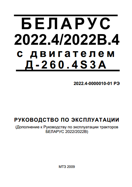
BELARUS 2022.4, 2022B.4 с двигателем ММЗ
(zip, 6 Мб)
-
BELARUS 2022.4, 2022B.4 с двигателем DEUTZ
(zip, 3 Мб)
-
BELARUS 2022.4К с двигателем Cummins (2021 год)
(pdf, 38 Мб)
-
BELARUS 2022.5
(zip, 51 Мб)
-
BELARUS 2022.6 (2014 год)
(zip, 32 Мб)
-
BELARUS 2122.3, 2122.4 (2016 год)
(zip, 35 Мб)
-
BELARUS 2122.6 (2014 год)
(zip, 38 Мб)
-
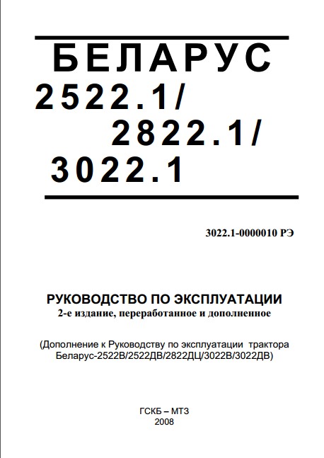
BELARUS 2522.1, 2822.1, 3022.1
(zip, 6 Мб)
-
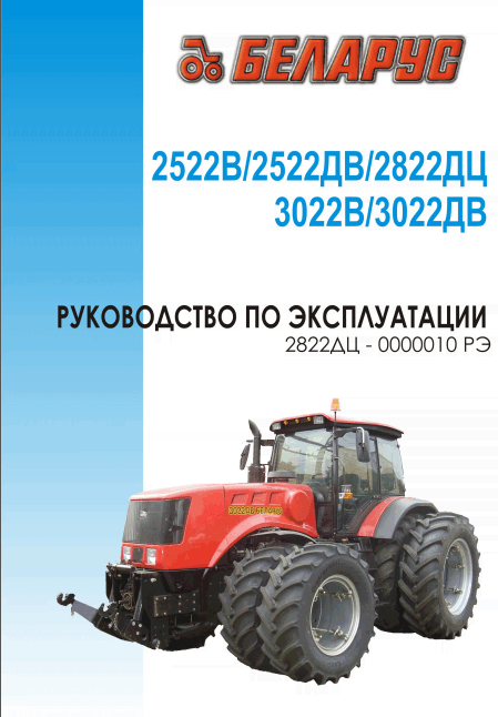
BELARUS 2522В, 2522ДВ, 2822ДЦ, 3022В, 3022ДВ
(zip, 76 Мб)
-
BELARUS 3022ДЦ.1 (2015 год)
(zip, 67 Мб)
-
BELARUS 3222, 3522
(zip, 57 Мб)
-
BELARUS 3522 с двигателем CATERPILLAR C9 (2016 год)
(zip, 82 Мб)
-
BELARUS 3522 с двигателями CATERPILLAR и CUMMINS
(zip, 85 Мб)
-
BELARUS 3522 с двигателями Caterpillar, Cummins, Deutz (2022 год)
(pdf, 82 Мб)
-
BELARUS 3522.5 (2012 год)
(zip, 65 Мб)
-
BELARUS 3525 с Caterpillar и Cummins (2019 год)
(zip, 84 Мб)
-
BELARUS 3525, 3525.5 (2016 год)
(pdf, 82 Мб)
|
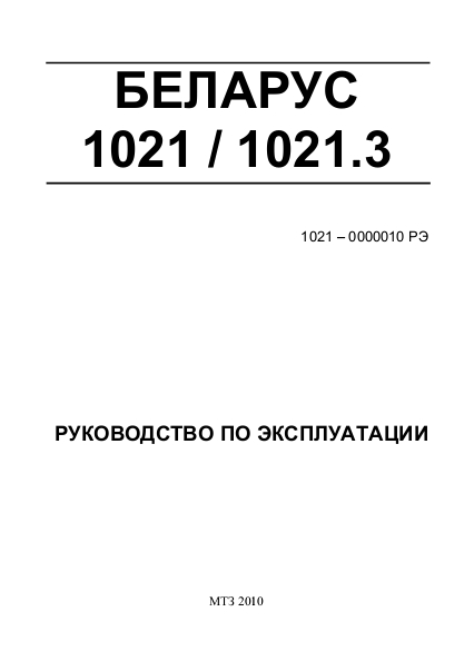
Руководство по эксплуатации тракторов МТЗ Беларус 1021, Беларус 1021.3 Скачать |
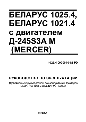
Руководство по эксплуатации тракторов МТЗ Беларус 1021.4, Беларус 1025.4 Скачать |
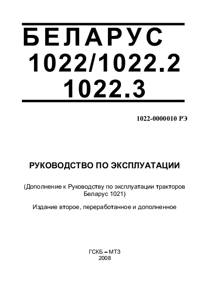
Руководство по эксплуатации тракторов МТЗ Беларус 1022, Беларус 1022.2, Беларус 1022.3 Скачать |
|
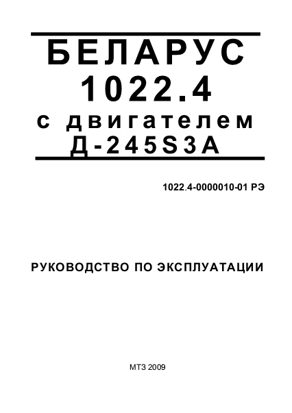
Руководство по эксплуатации трактора МТЗ Беларус 1022.4 Скачать |
Руководство по эксплуатации тракторов МТЗ Беларус 1025, Беларус 1025.2, Беларус 1025.3 Скачать |
Руководство по эксплуатации трактора МТЗ Беларус 1025.4 Скачать |
|
Руководство по эксплуатации трактора МТЗ Беларус 1025.4 DEUTZ Скачать |
Руководство по эксплуатации трактора МТЗ Беларус 1025.5 Скачать |
Руководство по эксплуатации тракторов МТЗ Беларус 1220.1, Беларус 1220.3 Скачать |
|
Руководство по эксплуатации трактора МТЗ Беларус 1220.4 Скачать |
Руководство по эксплуатации тракторов МТЗ Беларус 1221.2, Беларус 1221В.2, Беларус 1221.3 Скачать |
Руководство по эксплуатации трактора МТЗ Беларус 1221.4 Скачать |
|
Руководство по эксплуатации трактора МТЗ Беларус 1221.4 DEUTZ Скачать |
Руководство по эксплуатации тракторов МТЗ Беларус 1523, Беларус 1523В, Беларус 1523.3, Беларус 1523В.3 Скачать |
Руководство по эксплуатации тракторов МТЗ Беларус 1523.4, Беларус 1523В.4 Скачать |
|
Руководство по эксплуатации трактора МТЗ Беларус 1525.4 Скачать |
Руководство по эксплуатации тракторов МТЗ Беларус 2103 Скачать |
Руководство по эксплуатации тракторов Беларус 3222, Беларус 3522 Скачать |
|
Буклет Беларус 1523/1523В/1523.3/1523.4/1525 Скачать |
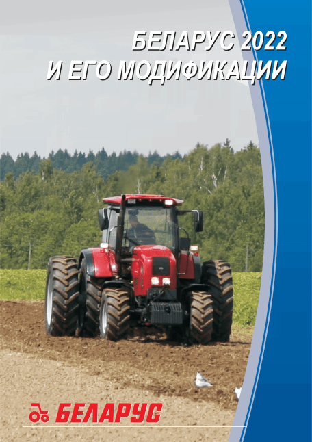
Буклет Беларус 2022 и его модификации Скачать |
Буклет Беларус 1221.2, 1221В.2, 1221.3, 1221.4, 1221Т.2 Скачать |
|
Беларус 1025, 1025.2, 1025.3 Перечень возможных неисправностей и способы их устранения Скачать |
Беларус 2022.5 руководство по эксплуатации Скачать |
Трактор гусеничный Беларус 1502 и его модификации руководство по эксплуатации Скачать |
|
Трактор Беларус 1221.5 руководство по эксплуатации Скачать |
Трактор Беларус 1523.5 руководство по эксплуатации Скачать |
Трактор Беларус 1822.3, 1822В.3,2022.3, 2022В.3 руководство по эксплуатации Скачать |
|
Трактор Беларус 2022.3, 2022В.3 руководство по эксплуатации Скачать |
Трактор Беларус 2022.4 руководство по эксплуатации Скачать |
Трактор Беларус 2022.4 с двигателем Д-260.4S3A руководство по эксплуатации Скачать |
|
Беларус 2522.2, 2822.1, 3022.1 руководство по эксплуатации Скачать |
Беларус 2522В/2522ДВ/2822ДЦ/3022В/3022ДВ руководство по эксплуатации Скачать |
Беларус 1220.5 руководство по эксплуатации Скачать |
|
Беларус 1021.5 руководство по эксплуатации Скачать |
Предлагаемое издание посвящено тракторам «Беларус» МТЗ-1221.2/1221В.2/1221.3. Указанная техника описана, а также проиллюстрирована схемами и чертежами. Обращаем внимание на то, что в руководстве могут не найтись некоторые изменения, которые были внесены в конструкцию отдельных деталей трактора.
Это связано с деятельностью производителя, стремящегося к постоянному усовершенствованию выпускаемых моделей. А потому, некоторая приведенная в руководстве по эксплуатации тракторов «Беларус» МТЗ-1221.2/1221В.2/1221.3 иллюстрационная информация может отличаться от реалий вашей техники. Необходимые данные вы легко сможете узнать из таблиц.
Руководство по эксплуатации тракторов «Беларус» МТЗ-1221.2/1221В.2/1221.3 Скачать Бесплатно
Скачать140,4 Мб
ПОКАЗАТЬ ВСЕСВЕРНУТЬ
- Главная
- Сервис и запчасти
Каталоги для скачивания
Тракторы, Спецтехника, Дизели
Тракторы
-
КДС BELARUS 800, 820, 890, 892, 900, 920, 950, 952, 90S, 92S, 92SL
(zip, 25 Мб)
-
КДС BELARUS 900, 900.2, 900.3, 920, 920.2, 920.3, 950, 950.2, 950.3, 952, 952.2, 952.3
(zip, 91 Мб)
Дизели
-
Д-260.2S2-64, Д-260.2S2-89, Д-260.2S2–60, Д-260.4S2-98, Д-260.4S2-68, Д-260.1S2- 59, Д-260.7S2-77, Д-260.16-88, Д-260.2S2-100, Д-260.2S2-101, Д-260.2S2-103
(zip, 7 Мб)
Спецтехника
Нормативы трудоемкости выполнения операций технического обслуживания (ТО) тракторов BELARUS-512, BELARUS-82.1/82.2, BELARUS-1221 (с модификациями), BELARUS-1523 (с модификациями), BELARUS-2022, BELARUS-3522, BELARUS-2522ДВ/3022ДВ и др.
Перечень сельскохозяйственных орудий и машин белорусского и импортного производства агрегатируемых с тракторами марки «BELARUS» тяговых классов 1,4 … 6 т.с.
- Manuals
- Brands
- Belarus Manuals
- Tractor
- 1221B.2
- Operator’s manual
-
Contents
-
Table of Contents
-
Bookmarks
Quick Links
BELARUS
1221.2/1221В.2
1221.3
1221 – 0000010РЭ
OPERATORS MANUAL
2009
Related Manuals for Belarus 1221B.2
Summary of Contents for Belarus 1221B.2
-
Page 1
BELARUS 1221.2/1221В.2 1221.3 1221 – 0000010РЭ OPERATORS MANUAL 2009… -
Page 2
Operators manual is meant for tractor operators, who operate BELARUS tractors. In view of P/A “MTW” policy directed to constant upgrading of produced goods, the con- struction of some units and parts of Belarus tractor may undergo changes which are not reflected in present edition. -
Page 3: Table Of Contents
Page Introduсtion……………………………………………………………………………..Safety requirements……………………………………………………………………… 7 Technical data……………….………….……………………….……………………….. 12 Operating controls and instruments…………………………………………………… Operating instructions…………………………………………………………………. Tractor preparing for operation…………………………………………………………. Adjustments……………………………………………………………………………… Aggregation……………………………………………………………………………….. Possible defects and ways of their elimination…………………..…………………. Scheduled technical maintenance……………………………………………………. Tractor transportation and its towing…………………………………………………. Tractor storage…….. ………………………………………………………………….. Appendix …….………………………………………………………………………………
-
Page 4: Introduсtion
Note: In the text of this manual references “left” or “right” are taken from viewpoint of observer standing behind along tractor strike. Note: In connection with carrying out regular works on improving Belarus tractors and working conditions alterations, not represented in this edition, may be made in de- sign.
-
Page 5
БЕЛАРУС-1221.2/1221В.2/1221.3 Введение when a tractor unit is used in the cross-country conditions (arable fields, peat beds, sandy soil etc.) because sudden stop of the tractor-machine unit can occur. Cross the mentioned sections with previously selected gear. Failure to comply with the stated operation rules will cause quick wearing out of gear splines and tooth-type couplings as well as synchronizers impairment Attention! If you hear skirr when shifting ranges and gears with the clutch pedal being depressed, immediately turn to a repair shop for malfunction repair. -
Page 6
БЕЛАРУС-1221.2/1221В.2/1221.3 Введение International Symbols Manufacturer uses standard international symbols regarding instruments and operat- ing controls. Symbols with their meaning are given below. — see operators manual — control operating direction — brake — fast — parking brake — slow — horn —… -
Page 7
БЕЛАРУС-1221.2/1221В.2/1221.3 Введение — lever — up — fan — control valve spool “lift” posi- — windshield washer tion — control valve spool “drop” — front windscreen wiper position — control valve spool “float” — rear windscreen wiper position — oil pressure in gearbox —… -
Page 8: Safety Requirements
BELARUS-1221.2/1221В.2/1221.3 Safety requirements SAFETY REQUIREMENTS Strict observance of safety precautions Safety measures during tractor op- and exact complying with the rules of eration tractor control and its maintenance se- Warning! Do not ever start the en- cure absolute safety of its operation.
-
Page 9
BELARUS-1221.2/1221В.2/1221.3 Safety requirements 13. Stop the tractor immediately if the engine or steering system fails. 20. To prevent tractor roll-over, be Remember, that with the engine careful during the driving the trac- shut down you will have to apply tor. Select a safe speed, corres-… -
Page 10
BELARUS-1221.2/1221В.2/1221.3 Safety requirements engage the 1st gear and apply the ration for work, maintenance, etc., parking brake. when the engine is shut down and brakes are applied. 24. When you use PTO-driven equip- ment, stop the engine and make 35. The cooling system operates under… -
Page 11
BELARUS-1221.2/1221В.2/1221.3 Safety requirements Safety requirements during • Use cab natural ventilation or cab operation and maintenance of air heating and cooling unit according to electrical equipment operation conditions. • If the time of continuous tractor op- 44. To avoid damaging the semicon-… -
Page 12
BELARUS-1221.2/1221В.2/1221.3 Safety requirements measures to prevent the flaming of other close cloth. Use the carbon- the washing liquid fumes. dioxide fire extinguisher. Do not ex- tinguish burning fuel with water 12. Do not operate the tractor in the fire dangerous areas when the bonnet 15. -
Page 13: Technical Data
BELARUS-1221.2/1221В.2/1221.3 Technical data TECHNICAL DATA Weights and dimensions Designation Value А Length, mm (with loads) 4500±40 Б Width, mm 2300±10 В Height, mm 2850±50 Г Wheelbase, mm 2760±30 Д Front track width, mm 1540…2090 Е Rear track width, mm 1530…2150…
-
Page 14
BELARUS-1221.2/1221В.2/1221.3 Technical data Tractor serial number is duplicated on the right sidemember and on the plate of right and left sidemembers. Engine serial number is also indicated on the engine identification plate located on the left side of cylinders block… -
Page 15
BELARUS-1221.2/1221В.2/1221.3 Technical data Gearbox identification number Transmission identification number Front driving axle identification number Cab serial number and OECD certificate number… -
Page 16
BELARUS-1221.2/1221В.2/1221.3 Technical data Engine Д-260.2 or Д-260.2С Д-260.2S2 Engine model MMP (Minsk motor plant) MMP (Minsk motor plant) Make Type six-cylinder, in-line six-cylinder, in-line Cycle 4 stroke 4 stroke Fuel injection system direct injection direct injection Compression ratio (calculated) Cylinder bore… -
Page 17: Air Cleaner
Filter elements: paper filters – elements 24 V starting motor made of highly porous paperboard. Starting aid: Turbocharger: ТКР-7 type, radial inward Heating plugs (for tractors “BELARUS- turbine and radial-flow compressor, as- 1221.3”) sembled on one shaft. Installation of foreign producers turbo- Clutch coupling chargers is possible.
-
Page 18
BELARUS-1221.2/1221В.2/1221.3 Technical data Gearbox 1. Type: 16/8, mechanical, step-wise, range. It provides with 16 forward gears and 8 reverse gears Tractor design travel speeds in km/h (GB 16/8, tyres 18,4R38) Tractor design travel speeds in km/h (GB 16/8, tyres 16,9R38) -
Page 19
BELARUS-1221.2/1221В.2/1221.3 Technical data 2. Type: 24/12, 16/8, mechanical, step-wise, range. It provides with 24 forward gears and 12 reverse gears. Tractor design travel speeds in km/h (GB 24/12, tyres 18,4R38) Tractor design travel speeds in km/h (GB 24/12, tyres 16,9R38) -
Page 20: Front Driving Axle
BELARUS-1221.2/1221В.2/1221.3 Technical data Rear axle Drive: Mechanical, by lever on control panel Main gear: a pair of bevel gears with spiral tooth. PTO end speed: Final drives: a pair of spur gears for Independent drive each sideboard. I — 540 rpm; N=60 kW (82 h. p.), Rear-axle drives: planetary type.
-
Page 21
BELARUS-1221.2/1221В.2/1221.3 Technical data Hydraulic lift linkage (HLL) • front and rear lamps; • dash board light and rear registra- Type: unit-principle with hydraulic lift tion plate light; device (with two plunger cylinders) It • hazard warning lights; provides 4 control modes of agricultur- •… -
Page 22: Operating Controls And Instruments
18. Instruments and starter switch Dash board 19. Blind plug Warning lights blocks 20. Blind plug. Battery disconnect switch for Electrical tachospeedometer tractor BELARUS-1221В.2 Panel for electrical equipment installation 21. Gas pedal Air recirculating shutters 22. Right brake pedal Windshield wiper switch 23.
-
Page 23
BELARUS-1221.2/1221В.2/1221.3 Operating controls and instruments 31. Range Shift Lever 37. Stop of position control lever 32. PTO control lever 38. Battery disconnect switch 33. Fuel delivery control lever 39. PTO shift lever (independent 34. FDA and rear axle differential lock control… -
Page 24
BELARUS-1221.2/1221В.2/1221.3 Operating controls and instruments Starter and instruments switch (1) The switch (3) has 4 positions: • 0 — “Off”; • I — “Instruments, control lamps unit, radio equipment power supply “On” • II — “Starter “On” (non-fixed position); • III — «Radio power supply when the engine is… -
Page 25
BELARUS-1221.2/1221В.2/1221.3 Operating controls and instruments 1. Instrument board The scheme of the instruments dashboard 80-3805010-Д1 and 826-3805010 is given in the section “Appendix”. The instrumentation includes: — instruments combination (Р2) with sensors; — the electric tachospeedometer (Р1) with the control board (А3) and sensors;… -
Page 26
1.2. Tachospeedometer control board (Fig. 2) The control board is installed in the instruments dashboard and serves for programming the tachospeedometer to the specific model of the Belarus tractor. Fig. 2. Control board (А3): 1. Button for setting the tachospeedometer to the programming mode and selecting the programming parameter on the tachospeedometer display (7).2. -
Page 27
– press the button (2) of the board and set the number of teeth (Z) according to Table 1 and value Rk according to Table 2: Table 1 Number of teeth Tractor model 54 (56)* “BELARUS-1221” and modifications * With driven gear 1522-2407122 Table 2 Tyre mark 18,4R38 Rk, m… -
Page 28
BELARUS-1221.2/1221В.2/1221.3 Operating controls and instruments The identification of the block outputs is given in Table 4. Table 4 Output Identification to the terminal “–“ to the power supply unit “+12В” to the board output “Parameter selection” to the board output “Parameter value”… -
Page 29
BELARUS-1221.2/1221В.2/1221.3 Operating controls and instruments 1.6. Combined indicator КД 8083 Fig. 4. Tachospeedometer (Р1): 1 – Engine rotational speed indicator (pointer indicator). 2 – PTO 1000 rotational speed scale (opposite to the respective value of the PTO rotational speed). 3 – PTO 540 rotational speed scale (opposite to the respective value of the PTO ro- tational speed). -
Page 30
BELARUS-1221.2/1221В.2/1221.3 Operating controls and instruments calculated speed reading is shown on the digital indicator and the LED located next to the symbol “km/h” lights up. The calculated motion speed (km/h). 1.7 Programming the indicator КД8083 Programming procedure: — remove the control board cover;… -
Page 31
Table 5 Gear ratio of the wheel reduction Tractor model gear (K1) 3.43 Belarus-1221 and modifications according to the number of gear teeth at the place of installation of the speed sensors (parameter “Z1”) from Table 6: Table 6 Number… -
Page 32
BELARUS-1221.2/1221В.2/1221.3 Operating controls and instruments Table 7 Tyre mark 18.4R38 Rk, m 0,829 Number coded 2. To display correctly the engine rotational speed, it is necessary to program the gear ratio of the alternator drive (parameter “K2”) from Table 8 in the specified order: Таблица… -
Page 33
The combined indicator (hereinafter referred to as the CI) and the control board (herein- after referred to as the CB) monitor the operational parameters of the systems and units of the Belarus tractors and provide the operator with the information on malfunction or failure of a particular system. -
Page 34
BELARUS-1221.2/1221В.2/1221.3 Operating controls and instruments Р1 – speed indicator (pointer-type); Р2 – engine rotational speed indicator (pointer-type); РS1 – LCD, multifunction indicator (precise description and principle of РS1 operation see below) РS2 – PTO rotational speed indicator (light indicator); HG1 – pilot lamp-alarm of the overvoltage in the on-board power supply system (red);… -
Page 35
BELARUS-1221.2/1221В.2/1221.3 Operating controls and instruments Table 10 Values of operation of the Segment location on the Values of operation of the “1000” scale segments scale “540” scale segments (rpm) (rpm) 1150 1050 750* HG10 2. In the presence of the PTO rotational speed sensor installed over the pinion of the… -
Page 36
BELARUS-1221.2/1221В.2/1221.3 Operating controls and instruments 1. Total astronomic time of running the engine in hours. The counter accumulates the information on the total engine running time and saves it on switching off the power supply. The reading range is from 0 to 99999 hours of the engine running. -
Page 37
BELARUS-1221.2/1221В.2/1221.3 Operating controls and instruments HG5 is the indicator of switching on the upper beam of the road headlights; it lights up when the upper beam of the road headlights is ON. Note! The indicators light up and go out synchronously with the changes in the states of the system sensors. -
Page 38
(right and left), over which the (rotational) speed sensors are installed; Select from the Table: Number of teeth (Z) Tractor model 54 (56)* Belarus-1221 and modifications * With driven gear 1522-2407122 Parameter “I” is the multiplying factor of the gear rate of the wheel reduction gear; Select from the Table… -
Page 39
PTO sensor “ZV”: Select from the Table Tractor model Gear ratio of the PTO drive Belarus-1221 and modifications (КV2) 0.46 — in the absence of the PTO rotational speed sensor (the signal from the phase winding of the alternator serves as a signal for indication of the PTO rotational speed) the value of the parameter “ZV”… -
Page 40
BELARUS-1221.2/1221В.2/1221.3 Operating controls and instruments justed content of the counter of the astronomic time of running the engine. This parame- ter is unavailable for measurement; it presents the precise (to 1/10 hours) value of the number of hours of the engine running. -
Page 41
BELARUS-1221.2/1221В.2/1221.3 Operating controls and instruments Table 11 Contact Address of the XP1 connector output To the terminal “–“ (common) To the power supply unit “+12 V” To the PTO rotational speed sensor To the rotational speed sensor “Left wheel” To the transmission control unit To the rotational speed sensor “Right wheel”… -
Page 42
BELARUS-1221.2/1221В.2/1221.3 Operating controls and instruments 5. The counter of astronomical hours of the engine running fails to accumulate the operating time: — Check the connection of the wire to the contact «8» of the instrument block (ХР1) and the presence of the frequency signal from the phase winding of the alternator. -
Page 43
BELARUS-1221.2/1221В.2/1221.3 Operating controls and instruments mode of displaying operating parameters specified below over the cycle. The faults are displayed on the LCD each time the instrument is switched on until the fault is eliminated. Note: — On switching on the power supply of the CI, the LED shows the information in the indication mode selected until the power supply of the CI is switched off in case of absence of the messages about faults. -
Page 44
BELARUS-1221.2/1221В.2/1221.3 Operating controls and instruments 5 – adjusting spacers; 6 – final pinion. 1.14 Combination meter (fig. 7) Engine cooling fluid temperature indi- cator (4) (with the emergency temperature control lamp) The indicator scale has three zones: • operating – 80 — 100°C – green;… -
Page 45
BELARUS-1221.2/1221В.2/1221.3 Operating controls and instruments Engine oil pressure indicator (5) (with emergency pressure drop control lamp) The indicator scale has three zones: — operating — 1,0 – 5,0 kgf/cm — non-operating — 0,0 – 1,0 и 5,0 – 6,0 kgf/сm IMPORTANT! See after the emergency pressure drop control lamp. -
Page 46
BELARUS-1221.2/1221В.2/1221.3 Operating controls and instruments 1.15 Connection of the combina- Block «Х2» tion meter Table 16 To integrate the combination meter to Contact Address the instrumentation system, the rear Reserved panel is provided with two blocks Х1 and Reserved Х2 (Fig. 8). -
Page 47
BELARUS-1221.2/1221В.2/1221.3 Operating controls and instruments IMPORTANT! To avoid inaccuracy in 1.16 Combination meter diagnostics the temperature indication, use the and troubleshooting ДУТЖ – 02М temperature sensors men- tioned above. 1. No backlight of the instrument scales on setting the SA10 central light switch: 1. -
Page 48
BELARUS-1221.2/1221В.2/1221.3 Operating controls and instruments if there is no breakage and the sensor is NOTE! If there is no fuel in the tank in good repair, replace the combination when switching on the indicator; the in- meter or repair the fuel level indicator. -
Page 49
BELARUS-1221.2/1221В.2/1221.3 Operating controls and instruments Front windscreen washer switch (1) Pressing the button (1) windscreen washer the switches on. Three-position light switch (2) The button (2) has three positions: 1 — “OFF”; 2 — “Dashboard lighting, clearance lights and number plate light ON”;… -
Page 50
BELARUS-1221.2/1221В.2/1221.3 Operating controls and instruments Steering-Wheel-Mounted ( Multifunction) switch (4) It ensures the switching-on of the turn indicators, toggling the beam of the road headlights (lower/upper beam), upper beam warning and horn beep . Turn indicator Turning the lever (4) of the steering-… -
Page 51
BELARUS-1221.2/1221В.2/1221.3 Operating controls and instruments Front windscreen wiper switch (1) Pressing the button (1) switches on front windscreen wiper. Cab heater and fan switch (2) Pressing the button (2) switches on the cab air ventilation. The switch has 3 positions: 1 —… -
Page 52
BELARUS-1221.2/1221В.2/1221.3 Operating controls and instruments Check indicators of the dashboard (Dashboard 80-3805010-Д1) 1 and 14 – Buttons for testing the ser- 9 – Rear axle differential locking control viceability of the control lamps unit. On lamp. The lamp (green) is on when… -
Page 53
BELARUS-1221.2/1221В.2/1221.3 Operating controls and instruments Control lamps of the dashboard (dashboard 826-3805010) 1 – Reserved indicator (green) 2 – Reserved indicator (green) 6 – Reserved indicator (blue). 3 – Reserved indicator (red) 7 – Rear axle differential locking control lamp (green). The lamp (green) is on 4 –… -
Page 54
BELARUS-1221.2/1221В.2/1221.3 Operating controls and instruments Fuses Three electric circuit fuse boxes are 12— Turn indicator relay (7.5 A); installed in the dashboard. To get ac- 13— Front working lights (25 A); cess to the fuses, remove the screw on the dashboard cover and open it. -
Page 55
BELARUS-1221.2/1221В.2/1221.3 Operating controls and instruments In case of fuse blowing due to a short circuit, proceed as follows: 1. Connect the wires from the pilot lamp to the terminals of the fuse box at the place of the fuse blown. -
Page 56
BELARUS-1221.2/1221В.2/1221.3 Operating controls and instruments Electric equipment connector components A combined multipin socket is designed for connecting the trailer electrical equipment or electrical equipment of trailed agricultural implement and ser- vice lamp. It is installed on the cab’s rear support. A plug of the wire bundle… -
Page 57
BELARUS-1221.2/1221В.2/1221.3 Operating controls and instruments Gearbox control (16F+8R) The gearbox is controlled by two levers: a lever of ranges shifting (1) and a lever of gears shifting (2). Select the required ranges and gears in accordance with the shifting patterns I and II as shown on the figure below. -
Page 58
BELARUS-1221.2/1221В.2/1221.3 Operating controls and instruments Gearbox control (24F+12R) (if installed) Gears shifting lever (2) The shifting pattern is shown in the fig- ure on the right (pattern I). “On” button (2а) of gearbox reducer low gear (L). On” button (2в) of gearbox reducer high gear (H). -
Page 59
BELARUS-1221.2/1221В.2/1221.3 Operating controls and instruments Control of the rear axle differential lock The rear axle differential lock is con- trolled by the button (4), located on the dashboard near FDA control button (2). Three position button (4) has the follow- ing positions: •… -
Page 60
BELARUS-1221.2/1221В.2/1221.3 Operating controls and instruments FDA drive control FDA drive is controlled by the button (2), located on the board above the right con- trol unit. The button (2) has three fixed positions: • “FDA is automatically “on” — on pressing the upper part of the button;… -
Page 61
BELARUS-1221.2/1221В.2/1221.3 Operating controls and instruments Switching on rear PTO shaft The lever (1) has 2 positions: • “PTO is engaged” — extreme upper position, • “PTO is disengaged” — extreme lower position. Independent and synchronous PTO drives The lever (2) has three positions: •… -
Page 62
BELARUS-1221.2/1221В.2/1221.3 Operating controls and instruments Hydraulic lift linkage control The hydraulic lift linkage is controlled us- ing two control levers (1) and (2), located on the right control board inside the cab. The draft control lever (2) is the nearest… -
Page 63
BELARUS-1221.2/1221В.2/1221.3 Operating controls and instruments Gearbox oil pump control The gearbox oil pump control lever (1) can have two fixed positions: I — “Pump drive from engine” (normal operating position) — the lever (1) is turned counterclockwise (when looking at GB from the left tractor… -
Page 64
BELARUS-1221.2/1221В.2/1221.3 Operating controls and instruments Changing of steering wheel position To adjust the height of the steering wheel, proceed as follows: • Remove the cover (2); • Unscrew the clamp (1) for 3…5 turns; • Set the steering wheel in the required position;… -
Page 65
BELARUS-1221.2/1221В.2/1221.3 Operating controls and instruments “BELARUS” 80-6800010/ move the seat from the “lower” position 80В-6800000 seat to the “middle” one or from the “middle” The 80-6800010 seat is distinguished position to the “upper” one smoothly lift from the 80В-6800000 seat by the… -
Page 66
Operating controls and instruments “Reverse position” (for the trac- tor with the reverse control panel “BELARUS-1221В.2”). To set the seat to the reverse position it is necessary to turn the clamps “Г” off and move them out of the panel brackets edges “Д”, lift the lever “Е”… -
Page 67
BELARUS-1221.2/1221В.2/1221.3 Operating controls and instruments The seat Grammer MSG85/721 (if installed) Important! Prior to beginning the opera- tion of the tractor, adjust the seat to the position being the most convenient for you. Perform all the adjustments while sitting on the seat. -
Page 68
BELARUS-1221.2/1221В.2/1221.3 Operating controls and instruments Cab Heater Control To put the cab heater into operation, proceed as follows: 1. Open the cock (1) from the left-hand side of the engine over fine fuel filter. Turn the cock handle counterclock- wise against the stop. Make sure the… -
Page 69
BELARUS-1221.2/1221В.2/1221.3 Operating controls and instruments Pneumatic system compressor con- trol The handle of compressor control has two positions: • “Compressor ON” – when turning the handle so that the arrow on the arm is directed backwards to tractor motion; • “Compressor OFF” – when turning the handle so that the arrow is di- rected forward to tractor motion. -
Page 70
BELARUS-1221.2/1221В.2/1221.3 Operating controls and instruments Reversible station controls. The additional reverse controls are located at the rear side of the cab as shown in the figure below: 1 — the clutch is disengaged when pressing the pedal. Clutch en- gagement takes place by pedal release. -
Page 71: Operating Instructions
BELARUS-1221.2/1221В.2/1221.3 Description and operation DESCRIPTION AND OPERATION Engine The tractor is equipped with a Д-260.2/Д- steel cloth is inserted. The bores for the 260.2С/Д-260.2S2 six-cylinder in-line in- cylinder sleeves and the oil passageway line, four-stroke turbo-charged, direct- are edged with sheet steel. When as-…
-
Page 72
BELARUS-1221.2/1221В.2/1221.3 Description and operation Fig. E-1. Д-260.2 engine (longitudinal section): 1 – crankcase; 1 – oil pump; 3 – vibration damper; 4 – crankshaft pulley; 5 – fan driving belt; 6 – valve-timing gear cover; 7 – jockey; 8 – alternator driving belt; 9 – fan; 10 – water pump; 11 – thermostat housing; 12 –… -
Page 73
BELARUS-1221.2/1221В.2/1221.3 Description and operation The piston pin is a hollow member made The camshaft (1) is driven from the of chrome-nickel steel. Pin axial displace- crankshaft through the valve timing gears ment in the piston-pin bosses is checked and rides on four supports. -
Page 74
BELARUS-1221.2/1221В.2/1221.3 Description and operation Fig. E-2. Д-260.2 diesel engine (cross section): 1 – camshaft; 2 – tappet; 3 – valve; 4 – valve guiding bush; 5 – pushrod; 6 – turbocharger; 7 – rocker arm; 8 – roller; 9 – spring retainer (disk); 10 – split cones; 11 – inner spring; 12 – outer spring; 13 – support; 14 –… -
Page 75
BELARUS-1221.2/1221В.2/1221.3 Description and operation The adjusting parameters of the fuel pumps are shown in the Table below Parameter description Unit of measure- Value ment РР6М10Р1f- 3492 (Д-260.2) 1. Average fuel feed per cycle through induction (high-pressure) pipe- /cycle lines, at 100 min rpm, no less than 2. -
Page 76
BELARUS-1221.2/1221В.2/1221.3 Description and operation — remove the hatch cover; — remove part of the fuel from the device glass tube; — back off 1…1.5 turn three M10 nuts which fasten the fuel-pump drive — rotate slowly the fuel pump shaft gear to the fuel pump drive flange;… -
Page 77
BELARUS-1221.2/1221В.2/1221.3 Description and operation The engine feed circuit (refer to Fig. E-3) consists of an air-cleaner, air-delivery conduit, induction and exhaust manifolds, turbocharger, exhaust silencer, fuel tank, coarse and fine fuel filters, fuel pump, injectors, as well as fuel-injection and delivery pipelines. -
Page 78
BELARUS-1221.2/1221В.2/1221.3 Description and operation The air cleaner (refer to Fig. E-4) is a dry- Fuel is to be cleaned from mechanical im- type filter with paper filtering cartridges. It purities by a coarse fuel filter (3) (refer to provides the three-stage purification. The Fig. -
Page 79
The principle of operation of the turbo- Installation of the charge air cooler charger is that exhaust gases from the cyl- (CAC) (BELARUS-1221.3) inders enter the gas-turbine chamber from The charge air cooler (13) (Fig. E-7) is in- the exhaust manifold. While expanding,… -
Page 80
BELARUS-1221.2/1221В.2/1221.3 Description and operation of the engine, and flows to the diesel suc- tion manifold. Fig. E-7. CAC outfit: 1, 4, 10 – air ducts; 2, 6 – clamp; 3, 5, 11 – junction branch-pipes; 7 – gasket; 8 – washer; 9 – bolt M8x16; 12 –… -
Page 81
BELARUS-1221.2/1221В.2/1221.3 Description and operation Fig. E-8. Lubrication system diagram: 1 – overflow valve; 2 – oil filter, paper; 3 – heat-exchanger; 4 – main oil pipeline; 5 – oil pressure sensor; 6 – manometer; 7 – turbocharger; 8 – fuel pump; 9 – compressor of the pneumatic system; 10 – intermediate pinion;… -
Page 82
BELARUS-1221.2/1221В.2/1221.3 Description and operation The engine cooling system is of a liquid The automatic mode is provided through a closed type, with forced circulation of the viscous friction coupling (12) (refer to Fig. coolant. The system consists of a cooling… -
Page 83
BELARUS-1221.2/1221В.2/1221.3 Description and operation Fig. E-9. Pump assembled with the clutch: 1 – fan blade; 2 – driven cover; 3 – hole for stop; 4 – stop nut; 5 – stop; 6 – stem; 7 – return spring; 8 –… -
Page 84
BELARUS-1221.2/1221В.2/1221.3 Description and operation Power Transmission Train The power train incorporates a clutch, Clutch transmission gearbox, FDA drive, FDA, and rear axle. It serves to transmit torque The clutch (Fig. E-10) is of friction, double- from the engine crankshaft to the front and dry-disk, permanently closed type. -
Page 85
(1), pressure disk (3), and the in- with washers (15). termediate disk (2) with three spikes on its surface which enter special slots of the Clutch control (BELARUS- flywheel. Two driven disks (26) together 1221.2/1221.3) with vibration dampers (9) mounted on the power shaft (7) form the clutch driven unit. -
Page 86
BELARUS-1221.2/1221В.2/1221.3 Description and operation Clutch control (BELARUS-1221В.2) I. Forward run The clutch is disengaged by stepping on initial position by the force of contracting the pedal (1), Fig. E-11а acting upon the springs (4, 8). To operate the hydraulic operating cylinder (2) of the hydraulic… -
Page 87
BELARUS-1221.2/1221В.2/1221.3 Description and operation Clutch casing unit (4 forward and 2 reverse gear ranges) with the intra-range gear shifting by The clutch casing houses drives of a con- means of synchronizers. The GB provides tinuous PTO, HLL oil pump, and oil pump… -
Page 88
BELARUS-1221.2/1221В.2/1221.3 Description and operation Fig. E-12.2. Shaft of downshift gears: 1 – primary shaft; 2, 4, 7, 8 – gears; 3 – coupling; 5, 9, 10 – bushings; 6 – retaining ring The speed-gear assembly consists of a The gear (4) of the 1… -
Page 89
BELARUS-1221.2/1221В.2/1221.3 Description and operation Fig. E-13. Synchronized transmission gearbox control mechanism: 1 – stop; 2 – ball; 3 – spring; 4 – arm; 5 – cover; 6, 7 – levers; 8 – casing; 9 – sphere socket; 10 – boot; 11 –… -
Page 90
BELARUS-1221.2/1221В.2/1221.3 Description and operation Fig. E-14. Gearbox: 1, 4, 14 – forks; 2, 5, 6, 10, 15 – dogs; 3, 13 – bolts; 7 – dog; 9 – pin; 11 – lock; 12 – spring; 8 – ball; 16 – filter; 17 – pump casing; 18 – inner shaft. -
Page 91
BELARUS-1221.2/1221В.2/1221.3 Description and operation 24F+12R gearbox (GB) (option) The transmission gearbox (Fig. E-15.1) is a mechanical-type fixed-ratio unit with speed ranges. It consists of a speed-gear assembly, downshift gear and reverse shaft, gear clus- ter, secondary shaft which are installed in the casing as well as the control mechanism and hydraulic system units. -
Page 92
BELARUS-1221.2/1221В.2/1221.3 Description and operation The speed-gear assembly is mounted of the 5 and 4 gear, respec- on the cover (54) and consists of the pri- tively. The driven pinions (43 and 41) of mary shaft (51) with driving pinions (2, 4,… -
Page 93
BELARUS-1221.2/1221В.2/1221.3 Description and operation The gear-cluster shaft 33 (see Fig. E- The sets of components on the primary, 15.1) is installed in the casing (1) and intermediate, secondary as well as down- rests in bearings (27) and (35). Gears shift-and –reverse gear shafts are tight- (32) and (34) are splined-mounted on the ened up by nuts (12, 15, 47 and 50). -
Page 94
BELARUS-1221.2/1221В.2/1221.3 Description and operation The speed range change-over mecha- Three dogs, a fork (8), ball-point lock (13) nism (Fig. E-15.4) is installed in the and parts of the two gear engagement transmission gearbox casing (1) and lockout mechanism are installed in the cover of the gear-shift mechanism (14) fork assembly (7). -
Page 95
BELARUS-1221.2/1221В.2/1221.3 Description and operation The high-to-low reduction gear stage changing the length of the pusher (7) with switch-over mechanism of the trans- further locking by a check-nut (8). The mission gearbox (Fig. E-15.5) cylinder (11) communicates with the hy- mounted on the gear-shift mechanism… -
Page 96
BELARUS-1221.2/1221В.2/1221.3 Description and operation Transmission Gearbox Reduction Gear Control System The system allows the reduction gear The electro-hydraulic control system stages to be switched over when the (Fig. E-15.6) involves a control panel (1) lever (3) is in its neural position only (con-… -
Page 97
BELARUS-1221.2/1221В.2/1221.3 Description and operation Engine Starting Interlock As a precautionary measure against the The shims (9) are provided to adjust the engine starting when range instant of contact opening (9). switched on, the tractor is equipped with a special interlock device (Fig. E-15.7). The… -
Page 98: Rear Axle
BELARUS-1221.2/1221В.2/1221.3 Description and operation Rear Axle The rear axle (Fig. E-16) consists of the housing, and the will transmission assem- final drive, differential assembled with a blies located in the half-axle housings. hydraulically-driven friction clutch used for locking, hub drives located in the rear axle Fig.
-
Page 99
BELARUS-1221.2/1221В.2/1221.3 Description and operation Final Drive The adjusting shims (34) with the thick- ness of 0.2 mm and 0.5 mm are inserted The final drive of a bevel circular-arc teeth between the flanges of the bearing bodies type consists of a final-drive bevel pinion… -
Page 100
BELARUS-1221.2/1221В.2/1221.3 Description and operation Differential Lock Clutch and Three-Disk Service Brake The multiple-disk hydraulically controlled brake housing (17) contains the brake differential lock clutch (1) (Fig. E-17) is lo- disks (16), pressure disks (13), intermedi- cated in casing (8) which is bolted to the… -
Page 101
BELARUS-1221.2/1221В.2/1221.3 Description and operation Automatic Differential Lock-Up (ADL) The ABD feature is designed to improve clutch (Fig. E-17) and an electro-hydraulic the tractor traction and adhesion proper- control system. The latter ensures two op- ties and off-road capability. It consists of a eration modes: “automatic”… -
Page 102
BELARUS-1221.2/1221В.2/1221.3 Description and operation Service Brakes (BELARUS-1221.2/1221.3) The tractor is equipped with three-disk dry The brake actuator is of mechanical type. brakes of an increased standard size. The Each brake is activated by a separate disks of the left- and right-hand brakes (2) pedal (23). -
Page 103: Parking Brake
BELARUS-1221.2/1221В.2/1221.3 Description and operation Parking brake The tractor is equipped with a dry two-disk of the cab. The lever is locked when set to parking brake of reduced standard size work by means of a stop catch (12) on the (with the diameter of 178 mm), attached to toothed sector (13).
-
Page 104
BELARUS-1221.2/1221В.2/1221.3 Description and operation Service Brake Controls (BELARUS- connected with the service brake cylinder 1221В.2) (5) through pipeline (1). The latter exerts its effect on lever (4) of the right-hand For operation in reverse, the reversible straight-move brake pedal by means of tractors are equipped with hydrostatic lever (6) and tie-rod (11). -
Page 105
BELARUS-1221.2/1221В.2/1221.3 Description and operation “Wet” Brakes and Rear Axle Differential Lock Clutch (Option) The tractors can be equipped with multi- a common oil bath; therefore it also made ple-disk service and parking brakes oper- as a “wet” one. ating in an oil bath. -
Page 106
BELARUS-1221.2/1221В.2/1221.3 Description and operation Parking Brake A 4-disk parking “wet” brake (8) is in- stalled in the same case as the multiple disks service brake. Its components are unified with those of the service brake. Differential Lock “Wet” Clutch The lock-up clutch (17) comprises six… -
Page 107
BELARUS-1221.2/1221В.2/1221.3 Description and operation Pneumatic equipment Single-Line Pneumatic Actuator of the Trailer Brakes The tractors can be equipped with either single- or double-line pneumatic actuator of the brakes of the trailers equipped with such actuator. The pneumatic system is also used to inflate tyres as well as for other purposes where energy of compressed air is required. -
Page 108
BELARUS-1221.2/1221В.2/1221.3 Description and operation The air distributor on the trailer op- matic actuator without trailer (for exam- erates to feed the compressed air from ple, when inflating the tyres) and in case the trailer bottle into the brake chambers of emergency detachment of the trailer. -
Page 109
BELARUS-1221.2/1221В.2/1221.3 Description and operation Double-Line Pneumatic Actuator of the Trailer Brakes Fig. E-21.4. Double-line pneumatic actuator of the trailer brakes 1 – compressor; 2 – pressure regulator; 3 – air bleeder valve; 4 – air bottle; 5 – emergence pressure indica- tor light;… -
Page 110
BELARUS-1221.2/1221В.2/1221.3 Description and operation their ends. The valve of the coupling cyclical reduction gear shaft (26) with GB heads prevents the exit of air when the pinion. pneumatic drive is used with no trailer at- The epicyclical PTO reduction gear is lo-… -
Page 111
BELARUS-1221.2/1221В.2/1221.3 Description and operation Fig. E-22. Rear PTO epicyclical reduction gear: 1 – bracket; 2 – hydraulic cylinder; 3 – eccentric axle; 4, 5 – lever; 6 – control roller; 7 – stop plate; 8 – end- piece fixing bolt; 9 – replacement end-piece stop plate; 10 – replacement end-piece; 11 – adjusting screws;… -
Page 112
BELARUS-1221.2/1221В.2/1221.3 Description and operation Rear PTO Control Mechanism The tractor is equipped with a hydrofi- • “PTO engaged” – uppermost position; cated control mechanism of the rear PTO • “PTO disengaged” – lowermost posi- (Fig. E-23). This mechanism consists of a tion. -
Page 113
BELARUS-1221.2/1221В.2/1221.3 Description and operation is connected, in turn, to the electro- and oil is delivered to the rod-free cavity hydraulic distributor (7) for switching on of the hydraulic cylinder for controlling the the front PTO drive. front PTO, and the rod cavity is con- nected with the drain. -
Page 114
BELARUS-1221.2/1221В.2/1221.3 Description and operation Front driving axle (FDA) Fig. Д-25 1 – reduction gear of final drive; 2, 15, 28 – adjusting shims; 3 – pivot axle; 4 – bolt; 5 — cap; 6 – oiler; 7, 10, 16, 27 –… -
Page 115
BELARUS-1221.2/1221В.2/1221.3 Description and operation The main gear. and differential covers. Driving disks, having The main gear is a pair of conical gear outer cogs, are connected to the cogs of the members with helical teeth. housing and differential cover, driven disks The axle drive gear 36 (fig. -
Page 116
BELARUS-1221.2/1221В.2/1221.3 Description and operation Fig. Д-26 1 – differential casing; 2 – driving disk; 3 – driven disk; 4 – press-on carrier; 5 – axis of planetary gears; 6 – planetary gear; 7 – differential cover; 8 – side gear; 9 – conical roller bearing. -
Page 117
BELARUS-1221.2/1221В.2/1221.3 Description and operation the bearing 29 and the nut 26. To prevent The inner cage of the reduction gear is com- turning-off the nut collar is center-punched in pressed by the collars 3 and 20 (fig Д-27). The the wheel flange groove. -
Page 118
BELARUS-1221.2/1221В.2/1221.3 Description and operation Electro-hydraulic FDA Drive Control System Fig. E-28. Rear axle differential lock-up (DL) and FDA drive control system: 1 – control panel; 2 – steering wheels turning angle sensor; 3, 10 – control electro-hydraulic distributors for the DL and the FDA drive, respectively; 4 – terminal blocks; 5 – connecting cable; 6 – DL control key; 7, 12 –… -
Page 119
BELARUS-1221.2/1221В.2/1221.3 Description and operation ATTENTION! 1. When reversing, NEVER engage the automatic FDA drive control mode; use the forced drive only. Use the forced drive mode of the FDA for short-run jobs only: to clear an obstacle or when running the tractor in reverse. -
Page 120
BELARUS-1221.2/1221В.2/1221.3 Description and operation The draft control handle (7) (Fig. E-29) is The additional position control handle located on the right-hand control panel (9), (8a) (Fig. E-29) is located on the rear of the the first from the operator’s seat. The op- tractor on the hydraulic power lift. -
Page 121
BELARUS-1221.2/1221В.2/1221.3 Description and operation The control unit is mounted in the mon- When the draft control is used, the oblock (1) (Fig. E-235) and consists of a position handle (6) should be shifted to position sensor in the form of a bracket… -
Page 122
BELARUS-1221.2/1221В.2/1221.3 Description and operation Hydraulic System Operation The hydraulic system for controlling the three-point RHL is equipped with the regulator-distributor built in the mon- oblock. The regulator-distributor pro- vides the system in the following modes: • draft control; • position control;… -
Page 123
BELARUS-1221.2/1221В.2/1221.3 Description and operation HLL Operation The HLL is controlled by means of two handles located on the right-hand con- trol panel in the cab: • draft control handle (2); and • position control handle (3). Position control 1. Set the draft control handle (2) to the foremost position in the direction of the tractor travel. -
Page 124
BELARUS-1221.2/1221В.2/1221.3 Description and operation Hydraulic lilt linkage based on the electro-hydraulic regulator of the RHL control The tractor is equipped with two Ц schematic hydraulic diagram of he hy- 90х220 vertical hydraulic cylinders built draulic system with the electric-hydraulic in the lift (without regulator) controlled regulator of the RHL control in shown in from the electro-hydraulic regulator. -
Page 125
BELARUS-1221.2/1221В.2/1221.3 Description and operation The functions of control of the RHL and mounted on the oil tank (1). The lever hydroficated working members of the control of the distributor (2) and НШ32-3 external consumers are implemented in the gear pump are similar for all the ver- the new hydraulic system (Fig. -
Page 126
BELARUS-1221.2/1221В.2/1221.3 Description and operation Fig. E-33. Electro-hydraulic unit 1 – ЕНR5-ОС electro-hydraulic regulator; 2 – adaptor plate; 3 – RS 213 “Mita” distributor (Finland) The electro-hydraulic unit (Fig. E-33) Company (Germany) and adaptor plate consists of distributing sections of the (2) manufactured by the MTZ. -
Page 127
BELARUS-1221.2/1221В.2/1221.3 Description and operation Electronic RHL control system Fig. E-35. Electronic RHL control system 1 – RHL control panel; 2 – electronic unit; 3 – RHL position sensor; 4 – button for remote control of lower- ing the RHL; 5 – button for remote control of lifting the RHL; 6 – left-hand force sensor; 7 – right-hand force sensor;… -
Page 128
BELARUS-1221.2/1221В.2/1221.3 Description and operation RHL Control Panel Fig. E-36. RHL control panel 1 – lowering speed control handle (clockwise – quicker, anti-clockwise – slower); 2 – handle for selecting the control method (clockwise – position one, anti-clockwise – draft one, intermediate – combination con- trol);… -
Page 129
BELARUS-1221.2/1221В.2/1221.3 Description and opera- tion In case of raising (“popping”) of the agri- tractor and the implement ganged. To cultural implement when passing avoid accidents, it is strictly prohibited through the pressed soil areas gashes, to use the buttons of mechanical… -
Page 130
BELARUS-1221.2/1221В.2/1221.3 Description and operation Fault Diagnostics The BOSCH electronic hydraulic control In case of medium faults, the control is system is provided with the self-testing ceased and the system is locked. The sys- capability and issues the code information tem cannot be controlled from the main con-… -
Page 131
BELARUS-1221.2/1221В.2/1221.3 Description and operation When the system detects a fault, proceed as follows: 1. Stop the engine; 2. Set the controls on the main control panel as follows (Fig. E-35b): • handle (7) for controlling the hitch linkage – to the “off” position;… -
Page 132
BELARUS-1221.2/1221В.2/1221.3 Description and operation List of possible defects and methods of their check-up Defect Defect description, possible Defect check-up method code cause Complex defects Fault in the circuit of control Disconnect the bundle from the electromagnet and the solenoid valve for lifting. -
Page 133
BELARUS-1221.2/1221В.2/1221.3 Description and operation Defect Defect description, possible Defect check-up method code cause tween the wires or locking turn until the defect is eliminated. When disconnect- of one of the remote control ing the buttons, the engine shall be stopped. If the buttons. -
Page 134
BELARUS-1221.2/1221В.2/1221.3 Description and operation Defect Defect description, possible Defect check-up method code cause is faulty. Cable breakage or and check the cable for mechanical damage. Over- shirt circuit in the sensor load of the force sensor is also possible. (Fig. E… -
Page 135
BELARUS-1221.2/1221В.2/1221.3 Description and operation Fig. E-37. Electric connection diagram of the RHL control system… -
Page 136
BELARUS-1221.2/1221В.2/1221.3 Description and operation Rear Hitch Linkage (RHL) The second-category three-point hitch linkage with the third-category connecting points serves for ganging the mounted and semi-mounted agricultural machines and implements with the following cou- pling members: • the length of the suspension axle “А”… -
Page 137
BELARUS-1221.2/1221В.2/1221.3 Description and operation Upper rod and angle braces The length of the upper rod (2) is adjust- able within 500…740 mm by means of the handle (3). The RHL is provided with two gear-type (adjustable) angle braces. Their length can vary within 580…665 mm by rotating… -
Page 138
BELARUS-1221.2/1221В.2/1221.3 Description and operation External tie-links Partial locking The horizontal movement of the imple- ment in the working position shall be pro- vided by connecting the tie-links to the lower holes of the brackets (1) and adjust- ing the length by means of the tie-links (2) -
Page 139
BELARUS-1221.2/1221В.2/1221.3 Description and operation Mounting the agricultural implements onto the tractor The most kinds of equipment can be mounted on the tractor by performing the following operations: 1. Lower the hitch linkage to the bottom position. Align the axles of joints of the… -
Page 140
BELARUS-1221.2/1221В.2/1221.3 Description and operation Universal traction-hitch mechanism The towing arrangement for working with two-ale trailer consists of the towing jaw (5) with the pivot (6). The jaw body is con- nected with the plates (4) which enter the slot of the guiding side pieces (3, 7) and fixed by means of four pins (12). -
Page 141
BELARUS-1221.2/1221В.2/1221.3 Description and operation Coupling hook Fig. E-38. Coupling hook The coupling hook (hydroficated) is in- tended for working with semi-trailers and agricultural machines based on them. It is mounted on the tractor with the lift-type guides of the traction-hitch mechanism. It… -
Page 142
BELARUS-1221.2/1221В.2/1221.3 Description and operation Adjustment of the hydroficated hook control mechanism and peculiarities of ad- justment with the electro-hydraulic regulator of the RHL control ATTENTION! Prior to beginning the work with semi-trailers as well as prior to each adjust- ment of the position sensor (in case of mount- ing of the EHR) determining the position of the lift levers (1) and (2) (see Fig. -
Page 143
BELARUS-1221.2/1221В.2/1221.3 Description and operation Hydrostatic Steering Unit (HSU) The HSU unit is designed to control turn- cylinders (9, 13) to perform the turn, feed ing of the steering wheels and to reduce pump (16) together with engine-operated steering wheel efforts when turning the drive, and hydraulic pipe fittings. -
Page 144
BELARUS-1221.2/1221В.2/1221.3 Description and operation Measuring Pump The measuring pump (Fig. E-41) consists through a driven shaft (4). The distributor of a pumping unit (I), distributor (II), a non- consists of a casing (10), sleeve (5) and return valve (9), two anti-shock valves (7),… -
Page 145
HSU of a Reversible Tractor (BELARUS-1221В.2) The HSU of a reversible tractor is a modi- operation to the run “in reverse”, and fication of the “Belarus” 1221 HSU and conversely, it is necessary but to set the includes all its components, namely: “forward travel-reverse”… -
Page 146
BELARUS-1221.2/1221В.2/1221.3 Description and operation Air Conditioning and Cab Heat- ATTENTION: during the operation in the cooling mode, the heater cock shall be ing System closed to prevent the simultaneous op- eration of the systems of heating and air Control of the climatic control system in cooling. -
Page 147
BELARUS-1221.2/1221В.2/1221.3 Description and operation The cooling circuit includes the compressor, condenser, drying filter with General arrangement and operation of the pressure sensor, monoblock of the the air conditioning and cab heating evaporator and radiator of the heater system (cooler-heater), fan of the cooler-heater,… -
Page 148
BELARUS-1221.2/1221В.2/1221.3 Description and operation Tractor cab roof Left view in the direction of the tractor forward travel Right view in the direction of the tractor forward travel Diagram of arrangement of the basic components of the air conditioning and cab heating… -
Page 149
BELARUS-1221.2/1221В.2/1221.3 Description and operation The climatic-control system begins func- When turning the switch clockwise, the tioning in the air conditioning mode when temperature decreases and when turning the engine is running, the desired rota- the same anti-clockwise – increases. The… -
Page 150
BELARUS-1221.2/1221В.2/1221.3 Description and operation specialized service station using the di- agnostic equipment. PRECAUTIONS: 1. Only the specially trained per- sonnel shall be allowed to perform the maintenance and repair of the air condi- tioning system components. 2. Any works related to uncoupling… -
Page 151: Tractor Preparing For Operation
BELARUS-1221.2/1221В.2/1221.3 Tractor preparing for operation TRACTOR PREPARING FOR OPERATION GENERAL REQUIREMENTS hydraulic system and hydrostatic steering system, and if necessary, add more; When putting a new tractor into operation • empty the fuel out of the fuel tanks and proceed as follows: fill them with settled fresh fuel: in winter –…
-
Page 152
Cold temperature starting (+4°С and below). For tractor “BELARUS-1221.3” IMPORTANT! To avoid damage of the drive train, do not push or tow the trac- tor to start the engine. -
Page 153
BELARUS-1221.2/1221В.2/1221.3 Tractor preparing for operation IMPORTANT! Fill the tanks at the end of each operating day to prevent con- densation in the fuel tank. Breakaway and tractor moving IMPORTANT! NOTE: Refer to the travel speed chart Shift gear ranges (by gear clutch) only in section «В»… -
Page 154
BELARUS-1221.2/1221В.2/1221.3 Tractor preparing for operation Do not start driving a tractor with heavy traction loading (for example, a plough IMPORTANT! To avoid noisy shifting, buried in soil). After shifting a gear, turn shift a range gear (4) only when a the parking brake off and engage the tractor is stopped. -
Page 155: Stopping The Tractor
BELARUS-1221.2/1221В.2/1221.3 Tractor preparing for operation Working brakes • switch PTO off; • put all distributor handles to a neutral When driving on the road at transport position; speed, both brakes pedals must be • pull the implement down to the ground locked together with a latch.
-
Page 156
BELARUS-1221.2/1221В.2/1221.3 Tractor preparing for operation When a 6-splined shaft tail is replaced with a 21-splined one, switch PTO drive to 1000 rpm and run the engine at 2156 rpm to obtain standard PTO speed of 1000 rpm. Warning! To avoid unexpected move- ment of the implement, disengage the PTO after each use. -
Page 157
BELARUS-1221.2/1221В.2/1221.3 Tractor preparing for operation Running-in transporting). Load the engine by not IMPORTANT! The first 30 hours of tractor more than 50% from its rated power. operation influences greatly tractor per- formance and operation life, especially its 6. Avoid continuous… -
Page 158: Adjustments
BELARUS-1221.2/1221В.2/1221.3 Adjustments ADJUSTMENTS Front wheels tread setting Front wheel tread can be adjusted from relative to a flange and a rim relative to a 1545 mm to 2090 mm. The tread size de- disk. pends on the mutual location of a disk The variants of the tread adjustment are stated below in Table K-1.
-
Page 159
BELARUS-1221.2/1221В.2/1221.3 Adjustments Disk and rim installation variants Disk offset Х, mm Tractor tread, mm (tyres 420/70R24) 1700 1800 -102 2020 -152 2090… -
Page 160
BELARUS-1221.2/1221В.2/1221.3 Adjustments Front wheels toe-in adjustments After a required tread width of the front wheels is set, check and if necessary ad- just the toe-in by changing the length of the steering rod (2). 1. Inflate the tires to the required pressure (see Table on page Л17.) -
Page 161
BELARUS-1221.2/1221В.2/1221.3 Adjustments Rear wheels tread setting 1. Jack up a rear part of the tractor until the wheels are above the ground. 2. Remove the nuts (1) and take off the wheels. 3. Loosen the clamping bolts (2) of the upper and lower shells (3) of the wheel’s… -
Page 162
BELARUS-1221.2/1221В.2/1221.3 Adjustments Doubled rear wheels tread sizes Кабина Fig. К-4. Installation scheme of doubled rear wheels with spacer for rows of 450 mm or 700 mm: 1 — wheel; 2 — nut; 3 — bolt; 4 — spacer; 5 — hub; 6 — elongated bolt. -
Page 163
BELARUS-1221.2/1221В.2/1221.3 Adjustments PTO adjustment The distance “A” (see picture Ж-6) be- ATTENTION! tween an upper point of the cylinder rod 1. Before starting PTO adjustment, set head (8) and hydrocylinder head (7) is an “an independent/synchronized PTO” external indication of the wear factor of the modes shifter to a middle (neutral) PTO brakes bands’… -
Page 164
BELARUS-1221.2/1221В.2/1221.3 Adjustments External adjustment of PTO band brakes Fig. К-6 1. Set PTO rod (1) to position «Off» (an Repeat the above-mentioned operations extreme lower position) as described in until a specified distance «А» is obtained the figure К-5. for both PTO engaged and disengaged modes. -
Page 165
BELARUS-1221.2/1221В.2/1221.3 Adjustments PTO internal adjustment 8. Fasten the adjusting screws (11) in 1. Move a PTO rod (1) up to position turn with torque of 8…10 N•m (0,8…1 “On” (see Picture Ж-6). kgf m), then unscrew them by 1,5…2,0 2. Stop the engine. -
Page 166
BELARUS-1221.2/1221В.2/1221.3 Adjustments To choose a clearance, tighten a nut (30), Splint the nut (30) without turning it off to check bearings axial play and turn a gear match the slits with apertures for a cotter (16) over a flange (22). If there is an axial pin. -
Page 167
BELARUS-1221.2/1221В.2/1221.3 Adjustments FDA drive switch adjustment Fig. К-9а If FDA can not be engaged in an automat- of the switch should be opened (see ic mode, or if it is necessary to change a Picture Ж-9а (II)). The switch (5) is ad-… -
Page 168
BELARUS-1221.2/1221В.2/1221.3 Adjustments Checkup and adjustment of the single –wire pneumatic system brake valve and its drive Do the adjustment of the brake valve drive by the unpressed pedals of the operator brakes and a fully disengaged parking brake, which are to be preliminary ad- justed. -
Page 169
BELARUS-1221.2/1221В.2/1221.3 Adjustments Checkup and adjustment of the double –wire pneumatic system brake valve and its drive Do the adjustment of the brake valve drive coupling head doesn’t reach a required by the unpressed pedals of the operator limit, replace the brake valve (3). -
Page 170
BELARUS-1221.2/1221В.2/1221.3 Adjustments Checkup and adjustment of a pneumatic system pressure regulator If a pressure regulator is faulty or after its disassembling for cleaning or changing worn-out parts, do adjustments in the fol- lowing order: • connect a pressure gage with a scale graduation of 0,1…0,2 kgf/cm… -
Page 171
BELARUS-1221.2/1221В.2/1221.3 Adjustments Clutch pedal free travel adjustment at forward motion (BELARUS-1221B.2) The free travel of clutch pedal should stay within ranges 30…40mm. To adjust the clearance between the tappet of the operating cylinder (2) and (2) and a hydraulic cylinder guide bar (3) proceed as follows. -
Page 172
BELARUS-1221.2/1221В.2/1221.3 Adjustments Clutch pedal free travel adjustment at reverse motion (BELARUS-1221В.2) • unlock and remove a pin (2); • move a hood (11) out and loosen a lock-nut (10); • rotating a fork (9) of a pusher (6) of the… -
Page 173
BELARUS-1221.2/1221В.2/1221.3 Adjustments Brakes control adjustment at reverse motion (BELARUS-1221В.2) • Adjust a right pedal travel of a forward running working brake within the limits of 115…125 mm (see Section Н «Routine maintenance»); • Unlock and remove a pin (4). Move a hood (2) out and loosen a lock-nut of the fork (5);… -
Page 174
BELARUS-1221.2/1221В.2/1221.3 Adjustments Adjustment of the hydraulic cylinder of the reduction mechanism high and low gears switch To adjust the cylinder (1), move the pis- ton inside the cylinder up to the stop. Turn the lever (4) contraclockwise engag- ing the GB reducing gear. Screw-in the cotter-pin (3) at 8-9 turns, then lock it with the nut (2). -
Page 175: Aggregation
The section “TRACTOR AGGREGATION” contains the necessary information on the pe- culiarities of the intended use of the BELARUS tractor of your model including the recom- mendations on the aggregation, selection of machines, conditions of safe use of the tractor…
-
Page 176
3.2 Types and classification of agricultural machine-tractor aggregates on the ba- sis of BELARUS tractors The agricultural aggregates operated on the basis of the BELARUS tractors are classi- fied according to the following operational signs: Kind of the process to be carried-out: ploughing, sowing, planting, soil- cultivating, harvesting and others. -
Page 177
BELARUS-1221.2/1221В.2/1221.3 Aggregation front and combined. Quantity of the jobs to be performed: similar tractor-based aggregates perform- ing a single job; combined or complex ones performing two and more jobs simultaneously by means of several machines; combined ones performing several jobs be means of a single machine;… -
Page 178
1. Aggregation of the attached machines (loaders, bulldozers) is not related to the in- tended use of the BELARUS tractor. 2. No permit for joint operation of the BELARUS tractors with the mounted, trailed, semi-mounted and semi-trailed machines is required provided such operation com- ply fully with this Operating Manual for the tractor and does not fall outside the al- lowable framework of its use. -
Page 179
The BELARUS tractor can be aggregated with the machines having the rated resis- tance of the tools of 20,0 kN. The grasp width of the aggregate and operating depth depend mainly on the specific resis- tance of the soils, which determine the range of operating speeds with the account of agricultural requirements. -
Page 180
It is necessary to keep also in mind that the speed and operating depth are often limited by the agrotechnical requirements. The determination and assessment of the possibility of aggregation of the BELARUS tractor with agricultural machines shall be performed in several stages. -
Page 181
When purchasing the new machines to be used together with the tractor, it is necessary to specify the presence of the necessary working equipment providing for the possibility of aggregating with the BELARUS tractor of your model. For the machines located behind the tractor and driven from the PTO, it is necessary to order the cardan shaft of the necessary length and type, with the respective coupling di- mensions. -
Page 182
BELARUS-1221.2/1221В.2/1221.3 Aggregation Stage V Checking the possibility of motion of the tractor aggregated with the machine including checking the turn angles and maximum height of lifting of the mounted attachment until it rests against the tractor members, sufficiency of the length and free space of the cardan shaft when performing turns and transferring the machine to the transport position. -
Page 183
The main condition of the optimal aggregation of the BELARUS tractor is proper use of the engine power which is characterized by the load factor expressing the degree of use of the tractor’s rated power for performing the jobs by the aggregated agricultural machines. -
Page 184
BELARUS-1221.2/1221В.2/1221.3 Aggregation chines, varying the grasp width, operating depth as well as motion speed in the process of the operating motion of the aggregate. If the efficient loading of the engine by varying the number of machines and operating speed is impossible, the respective partial operating mode should be chosen by reducing the fuel feed. -
Page 185
BELARUS-1221.2/1221В.2/1221.3 Aggregation Wheel tread setting Front wheels 420/70R24 (or 14.9R24) Wheels position Tread, mm А 1540 В 1635 С 1850 Д 1950 А’ 1700 В’ 1800 С’ 2020 Д’ 2090 Wheels position with a disk over- turn (A’, B’, C’, Д’) should be used in exceptional cases only. -
Page 186
BELARUS-1221.2/1221В.2/1221.3 Aggregation Rear wheels doubling for wheel specific pressure decrease on the ground Tread size Hub fixed Tire type in a set К , К , mm size Н , Н 18.4R38+18.4R38 16.9R38+16.9R38 Сдвоенные ступицы Doubled hubs Fig. Л-3 Rear wheels doubling for inter-row cultivation of the crops using extra tires (option- Wheels tread К… -
Page 187
BELARUS-1221.2/1221В.2/1221.3 Aggregation Inter-row cultivation of the crops using single tires of the main configuration Wheels tread К, mm front rear Inter-rows width М, mm Basic cultivated crops 420/70R24 or 18.4R38 or 16.9R38 14.9R24 1540 (А) 1500 1650 (В) 1600 * Potatoes — in hackles, maize, cotton 1800 (С)*… -
Page 188
BELARUS-1221.2/1221В.2/1221.3 Aggregation Hitch and towing drawbar devices Rear hitch linkage HL-2 (3) Implements: mounted ones (ploughs, cultivators, seeders, milling cutters, etc.), semi- mounted ones (ploughs, soil-cultivating machines, seeders, potato harvesters, etc.). Ось переднего колеса Front wheel axle Верхняя тяга Upper rod Нижняя… -
Page 189
BELARUS-1221.2/1221В.2/1221.3 Aggregation Rear HL-2 (3) Characteristics Front HL-2 cat. 2 cat. 3 Lower rods solid separable Lower rods length: solid, mm Links hinges width: upper, mm lower, mm 38 or 45 38 or 45 Connecting elements rated diameter: upper rod pin, mm… -
Page 190
BELARUS-1221.2/1221В.2/1221.3 Aggregation Towing drawbar TD-2 (TD-2В – clevis; TD-2К — hook) Implements: semi-trailers (semi-trailers, fertilizer machines, etc.), trailers (disk harrows, soil-cultivators, hulling machines, coupling of harrows, cultivators, seeders, etc.). Сфера Sphere Fig. Л-8. A clevis (with a possibility of Towing drawbar… -
Page 191
BELARUS-1221.2/1221В.2/1221.3 Aggregation Towing drawbar TD-3B (clevis) Implements: trailers (motor-type double-axle trailers, etc.), semi-trailers (the same as for a TD-1). Fig. Л-9. A rotating clevis (with a possibility of a Towing drawbar vertical movement) 435…905 or Distance between the clevis and a supporting surface, 589…1059 (with a clevis overturn) -
Page 192
BELARUS-1221.2/1221В.2/1221.3 Aggregation Towing drawbar TD-1М-01 (drawbar) Implements: semi-trailers (the same as for a TD-2В and a ТD-3В), trailers (the same as for a ТD-2В and a TD-3В). Fig. Л-10. Towing drawbar A clevis with a possibility of a position change with reference to the PTO end… -
Page 193
BELARUS-1221.2/1221В.2/1221.3 Aggregation 3.5 Hitch linkage and hydraulic system use Rear hitch linkage of HL-2 type is produced in accordance with GOST 10677 (corres- ponds to the cat.2 according to ISO 730/1) with the possibility of modification according to the connecting dimensions for HD-3 (Category 3). Due to this the tractors are equipped with transitional bushings of lower and upper rods, which are installed in the rods hinge pivots, connected to the implement. -
Page 194
BELARUS-1221.2/1221В.2/1221.3 Aggregation D. Altering the length of both braces and upper rod for the transport position of the machine. — clearance: at least 300 mm; — sufficient safe distance between the members of the tractor and those of the machine excluding the contact of the machine members with the tractor (the clearance shall be at least 100 mm). -
Page 195
BELARUS-1221.2/1221В.2/1221.3 Aggregation The universal hydraulic system for controlling and adjusting the hitch linkages of the tractor provides additionally the following functional capabilities for the rear hitch linkage: — correction of the speed of lifting and lowering the lower rods; — restriction of the height of lifting the lower rods;… -
Page 196
BELARUS-1221.2/1221В.2/1221.3 Aggregation 3.6 Using the towing drawbar The tractor can be equipped with towing drawbars of various types providing the aggre- gation of trailed and semi-trailed machines, the coupling arrangements of which meet the following requirements: • compatibility of the coupling dimensions and the height of the drawbar position re- ferring to the supporting surface;… -
Page 197
BELARUS-1221.2/1221В.2/1221.3 Aggregation When using the rear PTO shaft at 540 rpm and front PTO shaft at 1000 rpm it is neces- sary to install a protective coupling from the PIS side, which limits the power take-off over the allowable values (not over 50-60 kW, respectively). It is possible to install the protec- tive coupling also to protect the drive from overloading. -
Page 198
BELARUS-1221.2/1221В.2/1221.3 Aggregation Schemes of attachment A cardan shaft length is deter- mined by distance L (the shaft is entirely moved) at horizontal posi- tion of the lower rods. A shaft lengthening is effected when lifting the implement, so it is necessary to check telescopic elements over- lap in an upper position. -
Page 199
BELARUS-1221.2/1221В.2/1221.3 Aggregation Cardan shaft installation Installation of a cardan shaft with a protective casing in combination with protective cover ensures safety of the connection (Picture Л-15а). End clevises should be in the same plane (Picture Л-15б). Cardan hinges inclina- tion angle (max. de-… -
Page 200
BELARUS-1221.2/1221В.2/1221.3 Aggregation 3.8 Determining the weight of the tractor, machine and ballast, loads on the towing drawbar and hitch linkage, tyres and axles of the tractor and steerability criterion The tractor and its structural members including also tyres are designed for trouble-free operation in a certain range of vertical loads and speeds specified in the Operation Manual for the tractor. -
Page 201
BELARUS-1221.2/1221В.2/1221.3 Aggregation The most accurate and reliable method of determining the weight and loads consists in weighing on the balance for motor transport means. Attention! The load on the hitch linkage, towing dawbar, axles, tyres and body of the tractor from the weight of the aggregated machines shall not exceed the maximum allowable values specified by the manufacturer. -
Page 202
BELARUS-1221.2/1221В.2/1221.3 Aggregation The load on the coupling arrangement of the machine can be determined by weighing the coupling arrangement on a beam crane through a dynamometer. Allowable loads Т on the axles of the tractor: Axle Range of the loads, min..max*, kN Front Тf… -
Page 203
BELARUS-1221.2/1221В.2/1221.3 Aggregation The tire is to be filled up as per standards (to 75% of its volume). Water (solution) leakage through a combined valve outlet is an indicator that the tire is filled up. As soon as the tire is filled up, screw the nipple back and pressure the tire up to its operative standards. -
Page 204
30…40 cm by 15..22 cm of cultivation depth on the middle-tight soil of normal humidity. Traditionally “Belarus” tractors in combination with units are used as per scheme of «tractor wheels are in a furrow». In this case a relevant wheels placing is required when working with standard, reverse and turning ploughs. -
Page 205
BELARUS-1221.2/1221В.2/1221.3 Aggregation a long straight stick is enough in the field environment. If the blades of the ploughshare are situated at different height, and the plough bodies are in different planes, then the plough shall move unsteady, the drawbar resistance and the fuel consumption will increase. -
Page 206
BELARUS-1221.2/1221В.2/1221.3 Aggregation than 1. Towing trailers and semi- The tractor is only ballasted with trailers standard basic or additional front and wheel weights manu- Selection of the towing а) on public roads 30,0 factured by the Republican Uni- drawbars for the aggrega- б) under field conditions and… -
Page 207
BELARUS-1221.2/1221В.2/1221.3 Aggregation 3.12 Safety of tractor aggregation To ensure the trouble-free operation of the tractor and aggregated machines as well as to exclude accidents and emergencies, we recommend you to read carefully this Operat- ing Manual for the tractor and follow strictly the recommendations contained herein at any time. -
Page 208
BELARUS-1221.2/1221В.2/1221.3 Aggregation On rear left part of the machines such as trailers or semitrailers there shall be a sign of limitation of the maximum speed of the MTA. The hole with the diameter of 24 mm in the both cheeks of the lifting device serve as a place of attaching the safety chains (ropes) on the tractor (the fasteners are included in the standard equipment of the technical mean to be aggregated). -
Page 209
BELARUS-1221.2/1221В.2/1221.3 Aggregation original manufacturer’s parts and assemblies have been replaces by other special or un- original ones not provided for by the manufacturer or where the seals are broken. 3.12.3 General guidelines for observing the aggregation safety precautions • Prior to beginning the work, check every time the tractor within the MTA for the mo- tion and operation safety. -
Page 210
BELARUS-1221.2/1221В.2/1221.3 Aggregation action of their inertial mass! Wait until the tools are completely stopped! • Prior to leaving the cab of the tractor, lower all the machine elements to the ground, stop the engine and remove the ignition key! •… -
Page 211
BELARUS-1221.2/1221В.2/1221.3 Aggregation and exclude the possibility of jamming! • The single-point coupling arrangement (hitch bar or tongue) of the machine shall have a support and safety connecting chain or rope. • The coupling arrangement of trailed and semi-trailed machines shall be stiff to ex- clude the collision of such machines with the tractor. -
Page 212
BELARUS-1221.2/1221В.2/1221.3 Aggregation tractor, make sure that the hydraulic circuits of the tractor and aggregate are depressur- ized! • When performing the hydraulic connection between the tractor and the machine, it is necessary to mark beforehand the components to be connected in order to avoid errors… -
Page 213
BELARUS-1221.2/1221В.2/1221.3 Aggregation including the towing drawbars and three-point hitch linkages. • Do not perform welding, brazing or mechanical works on the hydraulic accumula- tors. • When performing the maintenance works on the lifted machine, ensure the stable position of the machine by means of the respective supporting structures! •… -
Page 214
BELARUS-1221.2/1221В.2/1221.3 Aggregation Determine the degree of loading the machine with the process materials ensuring the safe operation of the tractor. Determine the necessity of twinning the wheels and filling the tyres with water solu- tion. Assign the required pressure in the tyres depending on the maximum load and speed under specific working conditions. -
Page 215: Possible Defects And Ways Of Their Elimination
BELARUS-1221.2/1221В.2/1221.3 Possible defects and ways of their elimination POSSIBLE DEFECTS AND WAYS OF THEIR ELIMINATION Defect, external manifestation Way of elimination ENGINE Engine doesn’t start Air in fuel system. Pump over system by means of pump of manual fuel pumping. Remove air inflow in fuel system (see section “Description and…
-
Page 216
BELARUS-1221.2/1221В.2/1221.3 Possible defects and ways of their elimination Defect, external manifestation Way of elimination turbed. angle. 3. Blue fume is emitted from the exhaust pipe Ingress of oil into the combustion chamber as a Replace the worn-out parts of the cup-piston result of wear of cup-piston group components group. -
Page 217
BELARUS-1221.2/1221В.2/1221.3 Possible defects and ways of their elimination Defect, external manifestation Way of elimination pressor. Units of system of automatic control of clutch of fan At temperature of water at output from diesel engine above 97° С fan of cooling system does not switch off, or at temperature of water below 70°… -
Page 218
BELARUS-1221.2/1221В.2/1221.3 Possible defects and ways of their elimination Defect, external manifestation Way of elimination lease bearing. Increased deformation of driven disks. Check butt beats of driven disk linins in re- lation to the external diameter of hub splines – it must be not more than 0,8 mm on the radius of 165 mm. -
Page 219
BELARUS-1221.2/1221В.2/1221.3 Possible defects and ways of their elimination Defect, external manifestation Way of elimination ring. or blisters on the face of the main and op- erating cylinders. Bleed the hydraulic sys- tem with brake fluid on reverse. Bleeding of brake fluid in connections and Tighten the connections, replace damaged pipelines in hydraulic drive system. -
Page 220
BELARUS-1221.2/1221В.2/1221.3 Possible defects and ways of their elimination Defect, external manifestation Way of elimination Oiled and worn lining of brake disc. Wash out overlays. If necessary replace discs. Hit of air in system of hydro system be- Add liquid up to label «Мах». Pump over cause of decrease of level of brake liquid system of hydraulic drive. -
Page 221
BELARUS-1221.2/1221В.2/1221.3 Possible defects and ways of their elimination Defect, external manifestation Way of elimination Slipping of drive clutch Check and regulate pressure in hydro sys- transmission (9…10 kilogram force/sm ). Replace worn out disks. Defects in electric line of front driving axle Determine and eliminate defects. -
Page 222: Hydraulic Lift Linkage
BELARUS-1221.2/1221В.2/1221.3 Possible defects and ways of their elimination Defect, external manifestation Way of elimination gaged. ing axle. When the disorder is found – eliminate it. Steering Increased effort on steering wheel Lack or insufficient pressure in hydraulic system of steering (Pressure in hydrosystem of steering should be 140…155 kilogram-force/sm…
-
Page 223
BELARUS-1221.2/1221В.2/1221.3 Possible defects and ways of their elimination Defect, external manifestation Way of elimination safety valve. The unloaded mounted attachment is not lifted; when setting any handles of the distributor to the “lifting” or “lowering” position, a specific sound emitted by the pump under load is heard. -
Page 224
BELARUS-1221.2/1221В.2/1221.3 Possible defects and ways of their elimination Defect, external manifestation Way of elimination At move of position handle to side of lowering pump does not unload, by engine stop, tightness is normal Turn out conical plug on upper surface of… -
Page 225
BELARUS-1221.2/1221В.2/1221.3 Possible defects and ways of their elimination Defect, external manifestation Way of elimination collector, remove hang-up of brushes and replace them in case they are worn out. Adjustment of solenoid starter switch is dis- Adjust relay. turbed. Blocker of engine start has actuated or its Install levels of gear box in neutral position, switch is faulty. -
Page 226
BELARUS-1221.2/1221В.2/1221.3 Possible defects and ways of their elimination Defect, external manifestation Way of elimination weakened Dirt hits under valve of connecting head Clean. Contact of dustproof cover with rod of con- Remove. necting head valve Parts of valve are deformed: diaphragm is… -
Page 227
BELARUS-1221.2/1221В.2/1221.3 Possible defects and ways of their elimination Defect, external manifestation Way of elimination lator of pressure, damage of return valve of regulator. Regulator works in mode of safety valve Adjusting cover is wrapped on bigger size. Adjust regulator. Jamming of unloading piston of diaphragm Disassemble regulator of pressure and eliminate jamming. -
Page 228
BELARUS-1221.2/1221В.2/1221.3 Possible defects and ways of their elimination Defect, external manifestation Way of elimination Check the integrity of the respective fuse erate (25А, see the electric diagram) in the fuse block located in the instrument dashboard. Replace the blown fuse. -
Page 229: Scheduled Technical Maintenance
Auxiliary fuel tank (if installed) adjustments, etc. If guards and casings Service brake master cylinder 0.20 were removed, make sure that they are tank (BELARUS-1221V.2) installed to their respective places before Clutch master cylinder tank you start working on the tractor. 0.20 (BELARUS-1221V.2)
-
Page 230
BELARUS-1221.2/1221V.2/1221.3 Scheduled maintenance Recommended fuels, oils, lubricants and special liquids F&L weight F&L F&L grade name and designation (volume) change filled into (refilling) tractor when interval, changing (refilling), kg (dm³) 1. Fuel At ambient temperature of 0°C and higher Fuel tank Shift-time (140±1) -
Page 231
BELARUS-1221.2/1221V.2/1221.3 Scheduled maintenance 2. Oils Diesel Summer (18.0±0.18) engine Motor oil Motor oils None Castrol crankcas Lukoil-Avang M-10DM, Turbomax M-10G SAE 15W-40 SAE 15W-40 Hessol Turbo State Diesel SAE Standard 15W-40 ГОСТ Essolube 8581―78 XD-3 Multigrate Shell Rimula Shell Rimula Plus… -
Page 232
BELARUS-1221.2/1221V.2/1221.3 Scheduled maintenance Brake Motor oil Motor oil Motor oil, Motor oil, (2.5±0.1) 1,000 housing M-10G2 M-10V2 same as into same as into to the level (500) (wet State State transmission transmission of check brakes) Standard Standard housing housing plugs ГОСТ… -
Page 233
BELARUS-1221.2/1221V.2/1221.3 Scheduled maintenance TAp-15V TAD-17i None HESSOL (4.0±0.04) 1000, or wheel transmission transmission BECHEM seasonal reduction oil, HYPOID gear State TSp-15K housing Standard State 80W-90 (portal, ГОСТ Standard planetary 23652―79 ГОСТ GL5; GL4 /parallel-s 23652―79, haft) TEP-15M TU 38.401-58-3 05-2002… -
Page 234
BELARUS-1221.2/1221V.2/1221.3 Scheduled maintenance Front TAp-15V TAD-17i Motor oil HESSOL (3.2±0.2) 1000, or transmission transmission M-10G2 BECHEM seasonal reducer oil, State HYPOID State TSp-15K, Standard Standard TSp-10 ГОСТ 80W-90 ГОСТ 8581―78 State 23652―79 Standard GL5; GL4 ГОСТ 23652―79, TEP-15M TU 38.401-58-3… -
Page 235
BELARUS-1221.2/1221V.2/1221.3 Scheduled maintenance tanks Industrial oil Industrial oil None None (9.0±0.35) 1000 or with BECHEM IGP-18 season hydraulic Staroil No. 38.10 units 1413 -97 (cylinder, TU 903.201. (winter) metering 042-05 MGE-46V pump) ADDINOL TU 38.001 Hydraulikol HLP 32 347-2000 TU 903.201. -
Page 236
BELARUS-1221.2/1221V.2/1221.3 Scheduled maintenance Rear Litol-24 BECHEM Solid oil S BECHEM 0.02 hitch grease LCP-GM grease LCP-GM ± 0.001 linkage State State pivoting Standard Standard shaft ГОСТ ГОСТ bushing 21150―87 4366―76 Solid oil ZH grease State Standard ГОСТ 1033―79 Rear Litol-24… -
Page 237
BELARUS-1221.2/1221V.2/1221.3 Scheduled maintenance Cooling Low-freezing Coolant None MIL-F-5559 once in 2 system coolant OZH-40 (BS 150), BELARUS-1 years (with heat Tosol (up to minus (USA) 221.2/1221 exchange Dzerzhinsky 40°C) FL-3 Sort r) of TC-40 (up to S-735 (UK) (26.5±0.2) OZH-65 minus 40°C) -
Page 238
BELARUS-1221.2/1221V.2/1221.3 Scheduled maintenance Maintenance after running-in (30 service hours) Inspect and wash the tractor. (Operation 25). Listen how all components of the Check and as necessary tighten the tractor operate. external threaded connections (Operation 42). Check tightening of the cylinder head fastening bolts (Operation 37). -
Page 239: Maintenance Table
Check operation of the engine, HSU, × brakes and instruments Check fluid level in the housings of main × cylinders of clutch and service brake control drives (BELARUS-1221V.2) Check fastening of air conditioner hoses × Check/clean air conditioner condenser × Check/clean air conditioning drainage ×…
-
Page 240
Each 800 service hours or once a year Check bearings of FDA reducer kingpin × axles Check tightening of the clamp bolts of × the CAC air ducts (BELARUS-1221.3) Tighten engine cylinder head fastening × bolts Clean engine air cleaner ×… -
Page 241
BELARUS-1221.2/1221V.2/1221.3 Scheduled maintenance Table, continued Nos. Interval, every hrs 1,000 2,000 total operation Contents of works Change oil in the transmission and the × hydraulic system and HSU oil tanks Change oil in the FDA final drive and × wheel reduction gears Lubricate the RHL right brace ×… -
Page 242
Important! After the maintenance, set in place all removed guards and casings before starting work. Hood (BELARUS-1221.2/1221V.2) The hood is hinged in the front of the tractor to ensure its rapid tilting forward to access the engine components. To raise the hood:… -
Page 243
BELARUS-1221.2/1221V.2/1221.3 Scheduled maintenance Hood (BELARUS-1221.3) The mask and hood are hinged on supports located on the front of the frame immediately behind the heat exchanger block of engine cooling. The fastening of the mask and hood is designed to allow quickly opening them and thus having a quick access to separate units of the tractor. -
Page 244
BELARUS-1221.2/1221V.2/1221.3 Scheduled maintenance Unmount-mount facing sides 1 – monocyclone; 2 – mask; 3 – hood; 4 – left side; 5 – right side; 6 – cable; 7 – lock; 8 – lock; 9 – cable; 10 – bracket; 11 – arm; 12 – arm; 13 – bracket; 14 – latch; 15 – lock. -
Page 245
BELARUS-1221.2/1221V.2/1221.3 Scheduled maintenance Scheduled maintenance operations After every service 10 hours or daily (whichever is earlier) Operation 1. Oil level in engine Check the oil level, installing the tractor on an even surface and not earlier than 3-5 minutes after stopping the engine when the… -
Page 246
BELARUS-1221.2/1221V.2/1221.3 Scheduled maintenance Operation 2. Coolant level in engine Caution! The engine cooling system operates under pressure which maintained by a valve in the heat exchanger cap. It is dangerous to remove the cap on a hot engine. Let the… -
Page 247
BELARUS-1221.2/1221V.2/1221.3 Scheduled maintenance Operation 3. Oil level in hydraulic system tank Before you check the oil level, install the tractor on a flat, horizontal surface. Stop the engine and brake the tractor with the parking brake. Check the oil level in the hydraulic system tank by the oil gauge glass (1) on the left side of the tractor. -
Page 248
BELARUS-1221.2/1221V.2/1221.3 Scheduled maintenance Operation 5. Discharge condensate from cylinders of the pneumatic system Pull the ring (1) towards and up, open the valve and hold it open until the complete condensate and dirt are fully discharged. Discharge condensate from cylinders on the left and right sides of the tractor. -
Page 249
A sign of a clean drain pipe is water dripping when the conditioner is operating in hot weather. Operation 6d*. * Discharge condensate from the engine heat exchanger (CAC) tanks (BELARUS-1221.3) To remove condensate from the engine heat exchanger… -
Page 250
BELARUS-1221.2/1221V.2/1221.3 Scheduled maintenance After every 125 service hours Perform the operations of the previous MS and the following ones: Operation 6e. Check/adjust tension of the air conditioner compressor drive belt. Tension conditioner compressor drive belt (1) (Figure 3.4) is deemed normal if deflection of its branch… -
Page 251
BELARUS-1221.2/1221V.2/1221.3 Scheduled maintenance Operation 8. Check generator drive belt tension The generator belt tension is deemed normal if the deflection of its branch between the pulleys of the crankshaft and the generator is 30 to 33 mm when it is pushed with a force of 40 N. -
Page 252
BELARUS-1221.2/1221V.2/1221.3 Scheduled maintenance Operation 12. Check the engine air cleaner Check condition of the paper filter elements (PFE) for presence of paper break and correct installation of the PFE. To check the basic filter element (BFE), proceed as follows: • unscrew the butterfly nut (2) and remove the pan (1);… -
Page 253
BELARUS-1221.2/1221V.2/1221.3 Scheduled maintenance After every 250 service hours Perform the previous MS and the following operations: Operations 13, 14. Clean the centrifugal oil filters of the engine and GB. • Remove the nut (1) and cap (2). • Insert the screwdriver (5) or a rod… -
Page 254
BELARUS-1221.2/1221V.2/1221.3 Scheduled maintenance Operation 15. Check the oil level in the hub casings and FDA final drive Check the oil level: • In the hub casings (left and right). As necessary, add oil to the level of the check-filler hole plugged with the plug (1). -
Page 255
BELARUS-1221.2/1221V.2/1221.3 Scheduled maintenance Operation 17. Change engine oil • Warm up the engine to its normal operating temperature (70°C min.). • Install the tractor on an even surface, stop the engine and brake the tractor with the brake. • Remove the cover (2) of the oil filler neck and unscrew the drain plug (4). -
Page 256
BELARUS-1221.2/1221V.2/1221.3 Scheduled maintenance Operation 18. Replace the PFE of the engine oil filter (performed simultaneously oil change) • Unscrew the cap (5) assembled with the paper filter element (6). • Unscrew the nut (1) and remove the bottom (2) with the gaskets (3) and (9). -
Page 257
BELARUS-1221.2/1221V.2/1221.3 Scheduled maintenance Operation 19. Lubricate the clutch release yoke bearing • Remove the plug (1) from the left side of the clutch housing. • Using a gun, make 4 to 6 injections of Litol-24 grease through the lubricator screwed into the housing of the release yoke to lubricate the release bearing. -
Page 258
BELARUS-1221.2/1221V.2/1221.3 Scheduled maintenance After every 500 service hours Perform the operations of the previous MS and the following ones: Operation 22. Check and adjust valve clearances in the engine Note: Check the clearances on a cold engine after checking the cylinder head bolt tightening (Operation 37). -
Page 259
BELARUS-1221.2/1221V.2/1221.3 Scheduled maintenance Operation 23. Discharge sediment from the fuel fine filter of the engine • Unscrew the air-bleed plug (1) by 2…3 turns. • First unscrew the sediment discharge plug (2) and discharge sediment from the filter housing until clean fuel emerges. -
Page 260
Scheduled maintenance Operation 26. Adjust free travel of the IMPORTANT! Make sure that the clutch clutch pedal (BELARUS-1221.2/1221.3) pedal always safely returns up to stop against the floor in the area of pedal free Free travel of the clutch pedal must be 40 movement. -
Page 261
BELARUS-1221.2/1221V.2/1221.3 Scheduled maintenance Operation 28. Brake pedal and parking brake lever travel The full travel of the right service brake pedal under a force of 120 N on the pedals must be 115 to 125 mm. Otherwise, adjust the brakes as follows: •… -
Page 262
BELARUS-1221.2/1221V.2/1221.3 Scheduled maintenance Before adjusting the parking brake, install the tractor on an even surface, stop the engine and lock the rear wheels from front and rear: • Shift the lever (1) to the extreme front (off) position. • Loosen the locknut (2) of the adjustment bolt (3) of the parking brake (on the right side of the tractor). -
Page 263
BELARUS-1221.2/1221V.2/1221.3 Scheduled maintenance Operation 29. Batteries CAUTION! batteries contain sulfuric acid that causes severe burns in case of skin exposure. Avoid exposure of hand skin, eyes and clothing to the acid. When the acid gets onto external body parts, rinse them with a strong jet of pure water. -
Page 264
BELARUS-1221.2/1221V.2/1221.3 Scheduled maintenance Operation 30. Draft and position control signal mixer (if installed) Lift the rear hitch mechanism to its highest position. The lever (1) must rotate in the zone between the marks I and III. If the lever travel does not match the above… -
Page 265
BELARUS-1221.2/1221V.2/1221.3 Scheduled maintenance Operation 33. Replace the oil filter of the hydraulic system Note: Perform subsequent replacements of the oil filter in the hydraulic system every 1,000 service hours. • Remove the screws (2), cover (1) and take out the filter element assembly using the stop (4). -
Page 266
BELARUS-1221.2/1221V.2/1221.3 Scheduled maintenance Operation 34. Clean generator Clean the generator from dust and dirt. Check and, if necessary, tighten the bolts fastening the generator. Check tightening torque generator terminals and other electrical equipment (starter, battery switch, etc.) Operation 35. Clean the cab heating and… -
Page 267
BELARUS-1221.2/1221V.2/1221.3 Scheduled maintenance Operation 35a . Replace filter drain ATTENTION: for replacement of the filter drain, contact a special service station. Replace only using special equipment. Operation 36. Check bearings of FDA reducer kingpin axles. Check and if necessary adjust the bearings (7) of the axles (5, 14) as described in the section “Adjustments”… -
Page 268
BELARUS-1221.2/1221V.2/1221.3 Scheduled maintenance After every 1,000 service hours Perform the operations of the previous MS and the following ones: Operation 37. Tighten engine cylinder head fastening bolts Check tightening of the fastening bolts of the cylinder heads on a hot engine proceeding as follows: •… -
Page 269
BELARUS-1221.2/1221V.2/1221.3 Scheduled maintenance Operation 38. Clean engine air cleaner Rinse the BFE in pure water at 35 to 45°C and dry for 24 hours. • Remove the monocyclone (7), clear the mesh, swirler and ejection slots from dust and dirt. -
Page 270
BELARUS-1221.2/1221V.2/1221.3 Scheduled maintenance Operation 39. Clean engine fuel coarse filter Rinse the engine fuel coarse filter, performing the following operations: • Shut off the fuel tank valve. • Unscrew the screws (1) fastening the carrier (3) and remove the bowl. -
Page 271
BELARUS-1221.2/1221V.2/1221.3 Scheduled maintenance Operation 40. Change filter elements of fine fuel filter • Unscrew the plug (1) and discharge sediment. • Unscrew the four nuts and remove the cover (3). • Rinse the housing and cover with pure diesel fuel. -
Page 272
BELARUS-1221.2/1221V.2/1221.3 Scheduled maintenance Operation 41. Check play in the steering Note: If tightening of threaded plugs link joints does not eliminate a gap in the joints, disassemble the joint and replace worn parts. When the engine is running, turn the… -
Page 273
BELARUS-1221.2/1221V.2/1221.3 Scheduled maintenance Operation 43. Change oil in the transmission housings, hydraulic system oil tanks, HSU and wet brake housings Before changing oil, operate the tractor to warm up the transmission and hydraulic system oil. • Install the tractor on an even surface,… -
Page 274
BELARUS-1221.2/1221V.2/1221.3 Scheduled maintenance • Change oil in a multi-disk brake housings operating in oil bath, proceeding as follows: unscrew the check-fill plugs (1) of the left and right housings; unscrew the drain plugs (2) and discharge oil as described above;… -
Page 275
BELARUS-1221.2/1221V.2/1221.3 Scheduled maintenance Operation 44. Change oil in the FDA final drive and wheel reduction gears • Operate the tractor and warm up the oil in the FDA housings. • Install the tractor on an even, horizontal surface. Stop engine. -
Page 276
BELARUS-1221.2/1221V.2/1221.3 Scheduled maintenance Operation 46. Lubricate the RHL • Remove the six bolts (1) and the drain pivoting shaft pipe. Sort out copper washers (two washers on each banjo bolt). Using a gun, inject grease into two lubricators located on the linkage bracket until the grease emerges from gaps. -
Page 277
BELARUS-1221.2/1221V.2/1221.3 Scheduled maintenance • Remove the bolts (3) fastening the injectors and remove the injectors (2). • Send the injectors to a shop for maintenance. • Install new injectors and removed parts in the reverse order. Tighten the bolts (3) fastening the injectors evenly in 2-3 steps. -
Page 278
BELARUS-1221.2/1221V.2/1221.3 Scheduled maintenance After every 2,000 service hours Perform the operations of the previous MS and the following ones: Operation 51. Engine fuel pump Model of fuel Adjustment of timing angle, deg. to pump The delivery commencement angle of the D-260. -
Page 279
BELARUS-1221.2/1221V.2/1221.3 Scheduled maintenance Operation 53. Flush the cooling system To flush, use a solution of 50-60 g of sodium carbonate and 1 liter of water. Proceed as follows: • Pour 2 liters of kerosene into the water heat exchanger and fill the system with the prepared solution. -
Page 280
BELARUS-1221.2/1221V.2/1221.3 Scheduled maintenance Overall maintenance Operation 55. Adjust oil pressure in the engine lubricating system If the oil pressure in the lubrication system of a warmed-up engine at a rated crankshaft speed is below 0.28 MPa (2.8 kgf/cm²), stop the engine and correct the fault. -
Page 281
BELARUS-1221.2/1221V.2/1221.3 Scheduled maintenance Operation 57. Maintenance of the cab ventilation and heating system For efficient operation of the ventilation and heating system, perform the following operations: 1. After pouring a cooling fluid (water) into the cooling system, start the engine and… -
Page 282: Tractor Transportation And Its Towing
BELARUS-1221.2/1221В.2/1221.3 Tractor transportation and its towing TRACTOR TRANSPORTATION AND ITS TOWING Tractors are transported by railway, auto Fasten ropes to the FDA beam or eyebolt transport, on trailers, by towing and under (1) and rear wheels half-axles as shown own power.
-
Page 283: Tractor Storage
BELARUS-1221.2/1221В.2/1221.3 Tractor storage TRACTOR STORAGE • Start the engine and check all devices, controllers and systems of the tractor. Before long-term storage of the tractor • Check light and audible signaling de- complete the following operations: vices. • Clean the tractor.
-
Page 284: Appendix
BELARUS-1221.2/1221В.2/1221.3 Supplement SUPPLEMENT Adjusting parameters of Д-260.2/Д-260.2S/Д-260.2S2 engine Designation Measuring unit Description Oil pressure in the lubrication system of warmed-up engine at rated speed of crank shaft МPа 0,28-0,45 (kgf/cm (2,8-4,5) Coolant temperature in coolant system °С 80-95 Alternator belt tension at 40 N (4 kgf) applied to the…
-
Page 285
BELARUS-1221.2/1221В.2/1221.3 Supplement Fuel pump 363.1111005-40.02 adjusting parameters (JSC “YAZDA”) at bench check Measuring Designation Value unit 1. Average cyclic fuel feed in high-pressure lines at rated speed of 100 rpm, not less /cycle 2. Rated speed of pump camshaft 1050+10 3. -
Page 286
BELARUS-1221.2/1221В.2/1221.3 Supplement Wire colors: Г – blue; Ж – yellow; З – green; К – red; Кч – brown; О – orange; С – grey; Ф – violet; Ч — black Circuit diagram of the control system of the rear axle and FDA DL. -
Page 287
BELARUS-1221.2/1221В.2/1221.3 Supplement Wire colors: Г – blue; Ж – yellow; З – green; К – red; Кч – brown; О – orange; P – pink; С – grey; Ф – violet; Ч — black Circuit diagram of control system of rear axle DL, FDA DL and front PTO DL. -
Page 288
BELARUS-1221.2/1221В.2/1221.3 Supplement Code Designation Fig. Note 1221-8700250-Д with FDA-1524 (or with FDA-1525) with FDA-1222 Wire colors: Г – blue; Ж – yellow; З – green; К – red; Кч – brown; О – orange; P – pink; С – grey; Ф – violet; Ч — black… -
Page 289
BELARUS-1221.2/1221В.2/1221.3 Supplement Indications on DL, FDA, PTO and reducer control scheme A1…A4 – Electromagnet of discrete hydraulic distributor (А1 — PTO, А2 — FDA, А3 — DL, А4 — reducer); С — Condenser NA-25В-4700мкФ; EL1…EL5 – Indicating lamp 12.3803-31 ТУ РБ 300228919.037-2002 (EL1 — FDA, EL2 — DL, EL3 — PTO, EL4 –… -
Page 290
BELARUS-1221.2/1221В.2/1221.3 Supplement Electrical scheme of tractor connections… -
Page 291
BELARUS-1221.2/1221В.2/1221.3 Supplement Variants of tractor connections… -
Page 292
BELARUS-1221.2/1221В.2/1221.3 Supplement 80-3805010-Д1 instrument board scheme Flasher unit Relay Relay of heater Relay of Starter Heating plugs Low beam High beam blocking starter relay unit relay relay blocking XS 5.10 XS 9.1 XS 9.2 XS 7.2 Chassis Chassis Illumination Parameter value… -
Page 293
BELARUS-1221.2/1221В.2/1221.3 Supplement 826-3805010 instrument board scheme… -
Page 294
BELARUS-1221.2/1221В.2/1221.3 Supplement Parts list of electric scheme of tractor and dash board units Кол Designation Description -во Кол Alternator 14V,1150W Designation Description -во GB1,GB2 Accumulator battery 12V, Stereo tape-recorder 88 ampere-hour Heating plug Low-frequency audible Control unit beep Conditioner High-frequency audible A4.1… -
Page 295
BELARUS-1221.2/1221В.2/1221.3 Supplement Designation Description Number 24 V batteries manual Wires colors: disconnector Disconnector of tractor- trailer unit sign Г – blue Ж – yellow SA2, Operating lights switch- SA3,SA11 З – green Fan switch К – red Windshield wiper switch Кч…

