-
Contents
-
Table of Contents
-
Bookmarks
Quick Links
ISM_LD Series
Vacuum Circuit Breakers
15kV, …20kA, …1000A
27kV, …16kA, …800A
With CM_1501 and CM_16 Series Control Modules
35
Application Guide MAN5002252
Revision 1
112
100
45
Related Manuals for TAVRIDA ELECTRIC ISM_LD Series
Summary of Contents for TAVRIDA ELECTRIC ISM_LD Series
-
Page 1
ISM_LD Series Vacuum Circuit Breakers 15kV, …20kA, …1000A 27kV, …16kA, …800A With CM_1501 and CM_16 Series Control Modules Application Guide MAN5002252 Revision 1… -
Page 3
The following application guide contains information necessary for the methods of use, installation, commissioning and operation of the ISM_LD series of breakers. It is absolutely necessary for the proper use of the vacuum circuit breakers to read this guide carefully before starting and to adhere to the instructions as well as the relevant regulations. -
Page 4: Table Of Contents
Table of Contents 1. Introduction • Glossary …………………………7 • Scope …………………………8 • Design and Method of Operation: ISM and CM ………………9 2. Receiving, Handling, and Storage • Receiving ……………………….. 12 • Trans port ……………………….13 • Handling and Incoming Inspection …………………..
-
Page 5
7. Product Line • Indoor switching modules (ISM) ………………….46 • Control modules (CM15 Series) ………………….46 • Control modules (CM16 Series) ………………….46 8. Dimens ions and Weights • Dimens ions and Weights of ISM ………………….48 • Dimens ions and Weights of the CM ………………….. -
Page 6: Introduction
Introduction…
-
Page 7: Glossary
Glossary The following abbreviations are used in this operating manual: Automatic reclosing Control module Close open cycle ISM: Indoor switching module LED: Light emitting diode MCB: Miniature circuit breaker Normally closed contact Normally open contact PCD: Pole center distance SCADA: Supervisory control and data aquisition SF6: Insulating gas sulfur hexafluoride…
-
Page 8: Scope
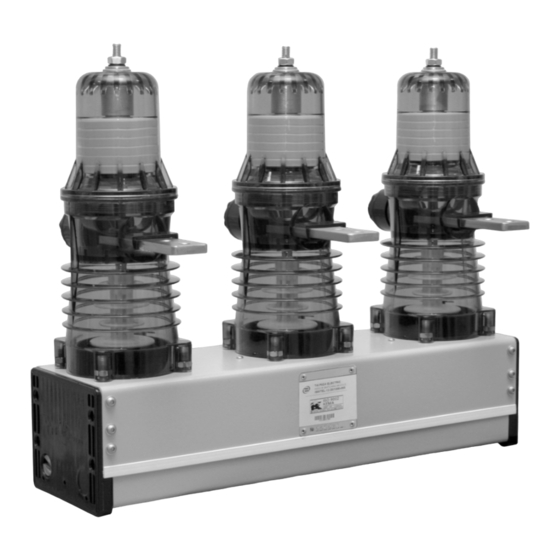
Scope In comparison to conventional circuit breakers, the Tavrida Electric vacuum circuit breakers is comprised of two components: · The ISM (Figure 1) · The CM for controlling the ISM (Figure 2) Both modules must only be operated together and are meant for indoor installations only. The possibility to choose the ISM and CM separately allows any type of switchgear to be easily equipped with regard to its primary and auxiliary circuits.
-
Page 9: Design And Method Of Operation: Ism And Cm
Design and Method of Operation: ISM and CM Indoor Switching Module (ISM) 1. VI 2. Upper terminal 3. Lower terminal 4. Movable contact with bellows 5. Flexible junction shunt 6. Drive insulator 7. Opening springs 8. Contact pressure spring 9. Actuator coil 10.
-
Page 10
Closing In the open position the contacts are kept open by the force of the opening springs. To close the contacts the coils of the magnetic actuators are excited by a current impulse from the close capacitors of the CM. The opening springs are compressed when the contacts close. In the closed position the contacts are kept closed only by means of the magnetic force. -
Page 11: Receiving, Handling, And Storage
Receiving, Handling, and Storage…
-
Page 12: Receiving
Receiving The following information is provided on the ISM packing cartons (Figure 9): · Handling symbols for transport and storage of the delivery unit (Figure 6) · Label 1 for manufacturers´ and product information (Figure 7) · Label 2 for logistics data (Figure
 1.
1. -
Page 13: Trans Port
Trans port ISM and CM shall be transported in the original packing only. The packed goods shall be handled in accordance with the handling symbols. Loading procedures for ISM packing units shall be carried out only with fork lifts or cranes. If possible the ISM packing unit shall be placed on a pallet.
-
Page 14: Rating Plates, Warranty Seals
Scope of delivery for the CM: Figure 14 Screwdriver Routine test certificate The intactness of the devices should be checked visually for: · Mechanical damage, scratches, discolouration, corrosion · Damage to the seals (Figure 19, Figure 20) Any transport damage must be reported immediately to the carrier in writing. Cases of damage must be photographically documented.
-
Page 15
Conforms to UL STD 508 Certi ed to CAN/CSA-22.2 No. 142-M1987 4000068 Tavrida Electric North America 1105 Cliveden Ave, Delta, BC, Canada 1-866-551-8362 Made in Russia Figure 16 Figure 17 The CM_16 has an additional label for factory programmable settings (Figure 18); see page 31 for detailed information on the settings functions. -
Page 16
Arrangement of the labels (Figure 18, Figure 19): 1. Rating plate 2. Serial number 3. Warranty Seal Figure 19 Labelling three-phase ISM Labelling single-phase ISM 1. Seal 2. Serial Number, date of manufacturing 3. Product code Figure 20 Labelling of the CM1501 Storage Should immediate installation not be possible, the ISM and CM shall be stored in the original packing under the following conditions:… -
Page 17: Ins Tallation
Ins tallation…
-
Page 18: General, Preparation
ISM Installation General, Preparation All applicable regulations must be adhered to during installation, commissioning and operation, including ANSI, IEEE, CEC, NEC, and other local, national or international standards / codes as required. Work shall only be performed by qualified personnel. Figure 21 The wearing of gloves for handling the parts during installation is recommended.
-
Page 19
Bus bars and cables shall be connected with the ISM primary terminals mechanically in a stress-free manner. No pressure, tension or torsion forces shall act on the ISM. To avoid unacceptably high mechanical loads on the ISM, the bus bar connections shall rest on additional supporting insulators (Figure 22). The following limits for maximum unsupported busbar length shall be applied to the design: ISM15_LD_X 0.5 m… -
Page 20: Minimum Clearances Due To Rated Ins Ulation Voltage
Minimum Clearances due to Rated Ins ulation Voltage The minimum clearances between the blank phases and to earth shall be according to VDE 0101. The minimum clearances between phase to Metal housin g phase and phase to earth are equal (Figure 24).
-
Page 21: Minimum Clearances Due To Electromagnetic Influence
Minimum Clearances due to Electromagnetic Influence Metal housin g The following clearances must be adhered to (Figure 28): I sc Minimum clearance (b) 16 kA, 20 kA 120 mm 25 kA, 31 kA 220 mm Figure 28 Coordination of Minimum Clearances Metal housin g In case that due to rated insulation voltage and…
-
Page 22: Protective Earthing
Protective Earthing For protection of personnel the metal housing of the ISM must be connected according to the applicable regulations, Bolt M12x25 such as NFPA-70, via the marked earth screw of the ISM to 50-70 Nm the earth arrangement of the particular panel. The earth Lock washer connection can be carried out with cable or a flat copper bar.
-
Page 23
The following conditions must be fulfilled in carrying out mechanical interlocking: · If the interlocking mechanism is attached to one of the interlocking pins, the weight of the directly attached movable part to the interlocking pins shall not exceed 0.35 kg. Exception is the single phase LD series, where the attached movable part shall not exceed 0.1 kg. -
Page 24
4. Attachment bolt for joining element To the joining element (3) a mass M ≤ 0.35 kg respectively attached. For three phase ISM locking levers can be executed with the Tavrida Electric interlocking lever set APTA 442611.004 (Figure 39) on either stub shaft (Figure 40). -
Page 25
Figures 41 and 42 show an example of a self-constructed trip unit (not included in the scope of supply). L = 19.5…50 mm B = 22…50 mm The length of L and B depends on the particular project. Figure 41 Figure 42 Connection between interlocking lever and synchronizing shaft… -
Page 26: Secondary Connections Of The Ism
CM Installation Secondary Connections of the ISM Secondary connections for three-phase ISM_LD types All three-phase ISM_LD have the same terminals (Figure 45). Connected to the terminal blocks XT1 and XT2 are 13 auxiliary switches (6 “NO”- and 7 “NC”-contacts) and the magnetic actuator coils. 1516 17 18 19 20 21 22 23 24 25 26 27 28 1 2 3 4 5 6 7 8 9 10 11 12 1314 Figure 45…
-
Page 27
Secondary connections for single-phase ISM_LD types All single-phase ISM have the same terminals (Figure 46). Connected to the terminal block XT1 are 5 auxiliary switches (2 “NO”- and 3 “NC”contacts) and the magnetic actuator coil. Figure 46 Terminal arrangement of the single-phase ISM Terminal arrangement ISM (single-phase) Terminal No. -
Page 28: Cm Connections
CM connections The connections for basic and extended functions of all available CM can be seen from the following terminal arrangements (Figures 47, 48, and 49). Figure 47 CM_1501_01 Terminal arrangement Terminal No. Connection Terminal No. Connection Terminal No. Connection Auxiliary power Ready (NO) Auxiliary switch ISM (AS1)
-
Page 29
Figure 48 CM_16_1(60), CM_16_1(220) Terminal arrangement Figure 49 CM_16_2(220) Terminal arrangement Terminal No. Connection Terminal No. Connection Terminal No. Connection Auxiliary power supply Output actuator coil CT input 1 input 1 (SC1) Auxiliary power supply Output actuator coil CT input 1 input 2 (SC2) Digital output 1 (NO) -
Page 30: Cm_16 Series Factory Programmable Options
To optimize the closing and trip pulses to the ISM actuators, this option sets various features of the CM_16 output power algorithm. Each model type of the ISM_LD series breakers can be selected. Note that connection to an ISM other than the one selected will produce a malfunction signal.
-
Page 31
Pre-Programmed Settings Code Designations Table Parameter Settings Option Code Breaker Type ISM15_LD_1 ISM25_LD_1 ISM15_LD_3 Undervoltage UV On UV Off UV Delay Undervoltage delay (0 — 60 s) 0 — 60 UV Reclosing Reclosing trips to lockout UV Reclosing Delay Reclosing Delay (15 — 60 s) 15 — 60 Digital Output 1 Disabled… -
Page 32: Ins Tallation Of The Cm: All Models
Ins tallation of the CM: All Models The installation of the CM is carried out according to the switchgear cubicle design either on the ISM or in the low voltage compartment of the switchboard. It must in all cases be separated from the high voltage compartment.
-
Page 33: Ins Tallation Of Secondary Cables Between Ism And Cm: All Models
Ins tallation of Secondary Cables Between ISM and CM: All Models In the high voltage compartment it is recommended to install secondary shielded cables between the ISM and CM in an earthed metal hose or an enclosed metal duct. Earthing point as near as possible at CM.
-
Page 34: Switching And Control Functions
Switching and Control Functions…
-
Page 35: Charging Of The Capacitors
Bas ic functions for all control modules Charging of the Capacitors Closing and trip capacitors of the CM are charged when CM is applied to the auxiliary power supply. The charged closing capacitors correspond with the charged springs of a conventional circuit breaker. After the failure of auxiliary power supply any pending trip or any trip command arriving to the CM up to 30s after failure of auxiliary power supply will be executed.
-
Page 36: Ism Forced Trip By An Undervoltage Relay (Optional — Cm_1501 Series)
Variant 1 — In the CM close command circuit Variant 2 — In the ISM auxiliary switch circuit Variant 3 — In the close command circuit and in the ISM position switch circuit If despite effective electrical closing lock-out a close attempt is made, the Malfunction LED will blink 2 times (see malfunction indication table, page 43).
-
Page 37: Antipumping Duty
Closed Antipumping Duty Close command Close contact Open Closed For close and trip inputs the following rule Open Trip contact is applicable: During close operation, if a Trip command trip instruction is received before the close Output to instruction becomes passive then the close magnetic instruction will be blocked.
-
Page 38: Commiss Ioning, Operation, Maintenance
Commiss ioning, Operation, Maintenance…
-
Page 39: Safety
When designing and mounting a panel for the first time an acceptance of the equipment must be carried out together with Tavrida Electric in order to ensure the installation conditions. The ISM must always be tested and operated together with the CM. Individual testing is not possible and may lead to the destruction of the ISM.
-
Page 40: Maintenance
Operating test While testing the functionality, at first the ISM must be separated from high voltage. · Turn on the CM auxiliary power supply and check the following operating indications: — The POWER LED must light up immediately. — The READY LED must blink during charging of capacitors and light up continuously within 10 s — The READY relay contact must close within 10 s.
-
Page 41: Signalling
Signalling…
-
Page 42: Led Indicators And Dry Contacts
LED Indicators and Dry Contacts Functionality Results LED indicators Dry contacts CM_1501_01 Ready Malfunction Ready Malfunction Switch on auxiliary power supply Power supply on BLINKING CM is ready to carryout close Operational command readiness Malfunction CM or ISM Malfunction See wiring diagram on page x for details on CM_1501_01 external signalling contacts NO/NC positions. CM_16 maintains the same LED indicator patterns as the CM_1501_01.
-
Page 43: Malfunction Indication Table
Malfunction Indication Table The self-monitoring system inside the CM detects eventual malfunctions and report them via the MALFUNCTION LED with various blink signals. The meaning of the blink codes and the variations per type of malfunction are shown in the following table. Recommendation Error Malfunction…
-
Page 44
· Usually failures need to be fixed to stop malfunction indication. During several malfunction variants of 2- or 5- blink failures, the malfunction indication will disappear with a trip CM command. · In case of internal CM failures please contact your nearest Tavrida Electric partner. -
Page 45: Product Line
Product Line…
-
Page 46: Indoor Switching Modules (Ism)
Indoor switching modules (ISM) Type Former Product Code Rated Rated Short Rated Pole Center Voltage Circuit Continuous Distance Current ISM15_LD_1(67) ISM/TEL-15-20/1000-067 15 kV 20 kA 1000 A 150 mm ISM15_LD_1(55) ISM/TEL-15-20/1000-055 15 kV 20 kA 1000 A 210 mm ISM15_LD_2 ISM/TEL-15-20/1000-055F 15 kV 20 kA…
-
Page 47: Dimens Ions And Weights
Dimens ions and Weights…
-
Page 48: Dimens Ions And Weights Of Ism
Dimens ions and Weights of ISM Dimensions and weights of the three-phase ISM 150 1 ± 150 1 ± 150 0.5 ± 145 0.5 ± 132 0.2 ± 15 kV VCB, 15 kV VCB, PCD 150 mm PCD 150 mm Weight: 36 kg ISM25_LD_2 Weight: 34 kg…
-
Page 49
210±1 210±1 149±0.5 262±0.5 132±0.2 27 kV VCB, PCD 210 mm Weight: 36 kg ISM25_LD_1(210) 275±1 275±1 181,5±0.5 327±0.5 132±0.2 27 kV VCB, PCD 275 mm Weight: 38 kg ISM25_LD_1(275) -
Page 50
15 kV VCB, continuous busbar, PCD 210 mm Weight: 37 kg By Special Order Only 27 kV VCB, continuous busbar, PCD 275 mm Weight: 39 kg By Special Order Only… -
Page 51
Dimensions and weights of the single-phase ISM 15 kV single-phase VCB, ISM15_LD_3 Weight: 13 kg 132±0.2 27 kV single-phase VCB, ISM25_LD_3 Weight: 13.5 kg… -
Page 52: Dimens Ions And Weights Of The Cm
Dimens ions and Weights of the CM CM_1501_01 Weight: 1.5 kg CM_1501_01(12) CM_1501_01(4) CM_16_1 Weight: 1.5 kg CM_16_1(60) CM_16_1(220) CM_16_1(60HS) CM_16_1(220HS) CM_16_2 Weight: 1.5 kg CM_16_2(220) CM_16_2(220HS)
-
Page 53: Circuit Diagrams
Circuit Diagrams…
-
Page 54: Ism_Ld With Cm_16_1 Control Module
ISM_LD with CM_16_1 Control Module…
-
Page 55: Ism_Ld With Cm_1501_01 Control Module
ISM_LD with CM_1501_01 Control Module…
-
Page 56: Technical Data
Technical Data…
-
Page 57: Indoor Switching Modules (Ism) — Ansi C37.09
Indoor Switching Modules (ISM) — ANSI C37.09 ISM15_LD_1 ISM25_LD_1 Type ISM15_LD_2 ISM25_LD_3 ISM15_LD_3 Rated voltage (U r ) 15 kV 27 kV Rated current (I r ) to 1000 A to 800 A Rated power frequency withstand voltage (U d ) 36 kV 60kV Rated lightning impulse withstand voltage (peak) (U p )
-
Page 58: Indoor Switching Modules (Ism) — Additional Standards
Indoor Switching Modules (ISM) — Additional Standards C37.74 Type C37.60 (With Exceptions) Applies to Breaker Types ISM25_LD_1, ISM25_LD_3 Rated voltage (U r ) 27 kV Rated current (I r ) to 800 A to 630 A Rated power frequency withstand voltage (U d ) 60kV Rated lightning impulse withstand voltage (peak) (U p ) 125 kV…
-
Page 59: Control Modules
Control Modules CM_16_1(220) Type CM_1501_01 CM_16_1(60) CM_16_2(220) Type of operation O-0.1s-CO-10s- O-0.3s-CO-10s- O-0.3s-CO-10s-CO- Rated operating sequence CO-10s-CO CO-10s-CO 10s-CO Maximum CO operating cycles per hour 19 — 72VDC Auxiliary power supply 24/60 85VDC to 85VDC to Auxiliary power supply 100/220 — DC 370VDC 265VCD Auxiliary power supply 100/220 — AC…
-
Page 60
CM_1501_01, CM_16_1, CM_16_2 Electromagnetic compatibility Interference immunity to voltage dips short Voltage oscillations of 15% inter-ruptions and voltage swings in accordance for a period of 2 to 3 s, with IEC 61000-4-11, Class V (A) periodic for 5 to 10 s Interference immunity to fast electrical transi- 4 kV ents/bursts to IEC 61 000-4-4, Class IV (A) -
Page 61
CM_16_2 Input for CT power supply Operating current range 2-300 A Power consumption per phase during charging trip capacitors — at 2 A 5 VA — at 5 A 12 VA — at 10 A 25 VA — at 30 A 120 VA — at 300 A 8 kVA… -
Page 63: Regulations And Ambient Conditions
Regulations and Ambient Conditions…
-
Page 64: Regulations
Regulations The ISM fulfils the requirements of the following standards: · DIN VDE 0670, Teil 1000 Germany · IEC 60056 International standard · IEC 62 271-100 International standard · IEC 60 694 International standard · GB 1984-2003 China · GOST 687-78 Russian Federation ·…
-
Page 65: Legal Information
Legal Information…
-
Page 66: Warranty
All products are shipped exclusively with original packing to ensure safe transport and avoid transport damage (see Packing, Goods Received). Tavrida Electric will not accept any claims for damages caused by improper transport, storage as well as unpacking. Transport damage must be reported in writing to the supplier as soon as it is discovered.
-
Page 67: Environmental Friendliness
© Copyright 2006; Tavrida Electric reserves the right to make changes to the design and data of their products. Tavrida Electric accepts no responsibility or liability for losses or damage caused by improper actions based on this publication.
-
Page 68: Non-Conformity Report
TAVRIDA ELECTRIC NA Service Department 1105 Cliveden Avenue Delta, BC, Canada V3M 6G9 E-Mail: info@tavrida-na.com Web: www.tavrida-na.com NON-CONFORMITY REPORT TAVRIDA ELECTRIC NA From: Service Department Phone: (604)-540-6600 Address: Fax: (604)-540-6604 E-Mail: info@tavrida-na.com Name: Web: www.tavrida-na.com Phone: Fax: E-Mail: Type designation: Serial No.:…
-
Page 69
Date:… -
Page 70
Tavrida Electric product. It contains information that is the intellectual property of Tavrida Electric and the document, or any part thereof, should not be copied or reproduced in any form without written permission from Tavrida Electric.
 1.
1. 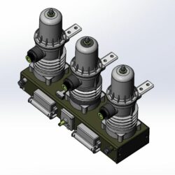
Коммутационный модуль TER_ISM15_LD_8(200_1) предназначен для коммутации электрических цепей при нормальных и аварийных режимах работы в сети трехфазного переменного тока частотой 50 Гц номинальным напряжением до 10(20) кВ включительно с изолированной, компенсированной, заземленной через резистор или дугогасительный реактор нейтралью. Выключатели предназначены для установки в новые ячейки КРУ, КСО
Состав: Модель одной деталью ![]()
Софт: STEP / IGES 214
Файлы:
Коммутационный модуль TER_ISM15_LD_8(200_1).IGS
Чтобы скачать чертеж, 3D модель или проект, Вы должны зарегистрироваться
и принять участие в жизни сайта. Посмотрите, как тут скачивать файлы
Еще чертежи и проекты по этой теме:
Вакуумные выключатели ISM15_LD_1(48), BB/TEL-10-20/1000 предназначены для коммутации электрических цепей при нормальных и аварийных режимах в сетях трёхфазного переменного тока (частота 50 Гц), номинальным напряжением до 10 кВ включительно с изолированной, компенсированной, заземлённой через резистор или дугогасительный реактор нейтралью.
ВВ/TEL-10 в своём составе содержит коммутационный модуль ISM15_LD_1(48) и модуль управления.
Малые габариты, свобода пространственного ориентирования и целая гамма различных исполнений позволяют адаптировать ISM15_LD_1(48), BB/TEL-10-20/1000 в шкафы КРУ (КСО) любых габаритов для обеспечения удобства эксплуатации или оптимизации полезного места.
Вес выключателей вакуумного выключателя ISM15_LD_1(48), BB/TEL-10-20/1000 составляет всего 34–56 кг. Это позволяет осуществлять монтаж бригадой из двух монтажников без применения специального подъемного оборудования, так как согласно действующим нормативным документам, распространяющимся на инженерно-технический персонал.
ВВ предназначены для установки в новых и реконструируемых комплектных распределительных устройствах станций, подстанций и других устройств, осуществляющих распределение и потребление электрической энергии во всех отраслях народного хозяйства, в том числе нефтегазодобывающей и перерабатывающей, нефтехимической, химической, горнорудной и других отраслях.
Условия эксплуатации: Климатическое исполнение выключателей — «У», категория размещения — «2».
Климатические внешние воздействующие факторы:
— верхнее рабочее значение температуры окружающего воздуха – плюс 55 °С (с учётом превышения температуры в КРУ или КСО);
— нижнее рабочее значение температуры окружающего воздуха – минус 45 °С;
— верхнее значение относительной влажности воздуха 100 % (с возможностью выпадения росы) при температуре плюс 25 °С;
— эффективное значение относительной влажности – 80 % при температуре плюс 20 °С;
— наибольшая высота над уровнем моря – 1000 м1;
— содержание коррозионно-активных агентов в окружающем воздухе – для атмосферы типа II (промышленная) по ГОСТ 15150.