-
Contents
-
Table of Contents
-
Bookmarks
Quick Links
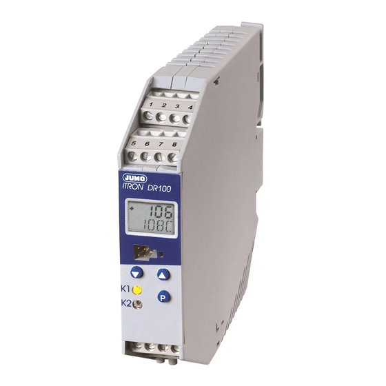
J iTRON DR 100
Type 702060
Compact Microprocessor Controller
B 70.2060.0
Operating Manual
08.04/00438833
Related Manuals for JUMO iTRON DR 100
Summary of Contents for JUMO iTRON DR 100
-
Page 1
J iTRON DR 100 Type 702060 Compact Microprocessor Controller B 70.2060.0 Operating Manual 08.04/00438833… -
Page 2: Table Of Contents
Identifying the instrument version ……… . . 4 Mounting .
-
Page 3
10 Technical data …………45 10.2 Analog inputs . -
Page 4
+49 661 6003-0 +49 661 6003-607 email mail@jumo.net All necessary settings are described in this Operating Manual. If any difficulties should still arise during start-up, you are asked not to manipulate the unit in any way. You could endanger your rights under the instrument warranty ! -
Page 5: Identifying The Instrument Version
Identifying the instrument version 702060/ . . . — . . . – . . . – . . / . . . (1) Basic type Output 1 Output 2 Comment 188 = 1 relay (changeover contact) — programmable, with factory setting 199 = 1 relay (changeover contact) — programmable, configuration to customer sprecification…
-
Page 6: Mounting
Mounting The controller is clipped onto a 35 mm DIN rail to EN 50 022 from the front. The mounting site should be free from vibration, to prevent the screw terminals from becoming loose. should also be free from corrosive media, such as strong acids and caustic solutions, dust, powder and other suspended substances, so that the ventilations slots cannot become clogged.
-
Page 7: Removal, Dimensions
Removal, dimensions h Insert a screwdriver into the relase slot, press it towards the unit and swing it downwards from the rail.
-
Page 8: Electrical Connection
Electrical connection Installation notes The choice of cable, the installation, the fusing and the electrical connection must conform to the requirements of VDE 0100 “Regulations on the Installation of Power Circuits with nominal voltages below 1000 V” , or the appropriate local or national regulations. The electrical connection must only be carried out by qualified personnel.
-
Page 9
Apart from faulty installation, there is also a possibility of interference with, or damage to, controlled processes due to incorrect settings on the controller (setpoint, data of parameter and configuration levels, internal adjustments). Safety devices independent of the controller, such as overpressure valves or temperature limiter/monitors should always be provided and should be capable of adjustment by specialist personnel only. -
Page 10
The electrical connection must only be carried out by specialist personnel. Supply AC/DC as per nameplate L1 line N neutral Analog inputs Thermocouple… -
Page 11
Analog inputs KTY11-6 PTC in 2-wire circuit With longer leads, resistance thermo- meters in 2-wire circuit must be changed over to C111=001 (3-wire circuit) and com- pensated with a resistor. Compensation condition: lead comp Standard signals: 0(4) — 20 mA, 0(2) —… -
Page 12
Logic output 0/5 V, 0/20 mA or 0/12V, 0/20 mA (short-circuit proof) Relay outputs changeover contact K1 without contact Type 702060/1XX… protection circuit make contact K1 make contact K2 Type 702060/2XX… Type 702060/2XX… It is not allowed to combine supply circuits with SELV circuits ! -
Page 13: Indications And Keys
Indications and keys LC display 2 lines 1st line: 4 places, with 7 segments each 2nd line: 5 places, alphanumeric Digit height 7 mm Display span -1999 to +9999 digit Decimal places none, one, two ° ° Unit F (process value display) Keys For operating and programming the instrument.
-
Page 14: Operation
Operation The JUMO iTRON DR100 is an electronic controller for mounting on a 35 mm DIN rail. The controller features a 2-line LC display for indicating the process value or setpoint, or for running dialogs. Just 3 keys are necessary for configuration. Parameter setting is arranged dynamically, and the value is accepted automatically after two seconds.
-
Page 16: Operating/Parameter/Configuration And Timer Levels
Operating/parameter/configuration and timer levels Depending on the configuration, AL or Pb 1 appears here…
-
Page 17
Operating level The setpoint SP 1 is defined here. With active setpoint switching via the logic input, SP 2 appears in addition. With active ramp function, the ramp setpoint is displayed. The setpoint is altered dynamically using the keys. The setting is accepted after approx. 2sec. Parameter Explanation Value range… -
Page 18: Operation Of The Timer Function
Operation of the timer function The timer can be started using the key, via the logic input or through power ON (stop, cancel, acknow- ledgement from the keys), if the timer is indicated at the operating level. Depending on the configuration of the logic input, an external button can take over the function of the key.
-
Page 19: Functions
Functions We recommend the following procedure: h Familiarize yourself with the controller functions h Enter the configuration codes and parameter values in the tables provided for this purpose in Chapter 8. Write down the appropriate values ( ), or mark selection with a cross ( The parameters and configuration codes are listed in the order of their appearance.
-
Page 20: Process Value Input
Process value input Symbol Notes Transducer/probe (process value input) v Chapter 7 “Configuration tables (C codes)” Unit of the process value (°C/°F)/decimal places of display v Chapter 7 “Configuration tables (C codes)” Start/end value of value range for standard signals →…
-
Page 21: Logic Input
Symbol Notes Filter time constant (damping) for adapting the digital input filter (0sec = filter off) v Chapter 8 “Parameter tables” if dF high: — high damping of interference signals — slow reaction of the PV display to changes in the process value — low cut-off frequency (2nd order low-pass filter) Logic input open…
-
Page 22: Controller
Symbol Notes Function of the logic input v Chapter 7 “Configuration tables (C codes)” Controller Controller structure Pb, dt The controller structure is defined via the parameters Example: Setting for PI controller r Pb .1=120, dt=0s, rt=350s Symbol Notes Controller type v Chapter 7 “Configuration tables (C codes)”…
-
Page 23
Symbol Notes Proportional band 1 (controller output 1) Proportional band 2 (controller output 2) Influences the P action of the controller. If Pb=0, the controller structure is not effective v Chapter 8 “Parameter tables” Derivative time Influences the D action of the controller. If dt=0, the controller has no D action. Reset time Influences the I action of the controller. -
Page 24
Symbol Notes Switching differential 1 (controller output 1) Switching differential 2 (controller output 2) for controllers with Pb 1=0 or Pb 2=0 v Chapter 8 “Parameter tables” Working point (basic load) output if PV=setpoint v Chapter 8 “Parameter tables” Output limiting — maximum output — minimum output v Chapter 8 “Parameter tables”… -
Page 25: Limit Comparator (Alarm Contact)
Limit comparator (alarm contact) lk1 —lk6:Monitoring referred to the setpoint. lk7 / lk8: Monitoring referred to a fixed value AL. w = setpoint, x = process value Symbol Notes Limit comparator function (lk1— lk8) v Chapter 7 “Configuration tables (C codes)”…
-
Page 26
Symbol Notes Switching differential of the limit comparator v Chapter 8 “Parameter tables” Limit value of limit comparator v Chapter 5 “Operation” Ramp function Ramp setpoint Process value power ON (SP 1 active) t2—t3 power failure or over/underrange t4—t5 ramp stop setpoint switching to SP 2… -
Page 27
Symbol Notes Ramp function (on/off, time unit) v Chapter 7 “Configuration tables (C codes)” Ramp stop via logic input (floating contact) v Chapter 7 “Configuration tables (C codes)” Ramp slope in °C/h or °C/min v Chapter 8 “Parameter tables”… -
Page 28: Self-Optimization
Self-optimization Self-optimization determines the optimum controller parameters for PID or PI controllers. The following controller parameters are defined: rt, dt, Pb 1, Pb 2, Cy 1, Cy 2, dF The controller selects procedure a or b, depending on the size of the control deviation: b) Self- Start a) Self-…
-
Page 29: Level Inhibit Via Code
Level inhibit via code As an alternative to the logic input, level inhibit can also be set via a code (logic input has priority). h Press simultaneously for 5sec and enter code for inhibiting h Acknowledge with Level inhibit via the logic input will lock the parameter and configuration levels (corresponds to code 011).
-
Page 30: Timer Function
Timer function Using the timer function, the control action can be influenced by means of the adjustable time ti0. After the timer has been started (by power ON, pressing the key, or via the logic input), the timer start value ti0 is counted down to 0, either immediately or after the process value has gone above or below a programmable tolerance limit.
-
Page 31
Notes on the timer function in conjunction with the ramp function Generally, the setpoints can also be approached using the ramp function. Stopping the timer does not affect the ramp function If control is active after the timer has run down, the current setpoint is approached with the ramp. Cancelation of the timer is followed by a setpoint step without ramp. -
Page 32
Symbol Notes Timer function v Chapter 7 “Configuration tables (C codes)” C120=1 Time-limited control: Control is switched off after the timer has run down (output 0%) C121=3, 4, 7 or 8 C121=1, 2, 5 or 6 Diagrams with and without start above tolerance limit. -
Page 33
Symbol Notes C120=2 Time-dependent setpoint switching: After starting the timer function, the process is con- trolled to setpoint SP2. When the timer has run down, the controller automatically switches to SP1. C121=3, 4, 7 or 8 C121=2 or 6 C121=1 or 5 Time-delayed control: The control action starts after the timer has run down. -
Page 34
Symbol Notes C120=4 Timer: After starting the timer function, ti0 is counted down to 0. The control action is indepen- dent of the timer. Here, too, the timer run-down can be signaled via an output. C121=1, 2, 5 or 6 Timer signaling C122=1 C122=3… -
Page 35
Symbol Notes Start condition for timer The timer start value ti0 is counted down as selected in the following events: 1. power ON or logic input/keys 2. start via keys/logic input 3. process value has reached tolerance limit (1°C or 5°C) (start via keys/logic input ) The position of the tolerance limit depends on the controller type: — 2-state controller (direct): tolerance limit above setpoint — 2-state controller (inverse): tolerance limit below setpoint… -
Page 36
Example After the start via the logic input or from the keys, the process must be controlled to a setpoint of 80°C for 30 minutes. The control action has to be canceled in the event of a power failure. Configuration: C111…C116: controller programming C117=5: logic input = timer control C120=1: timer function = time-limited control… -
Page 37: Configuration Tables (C Codes)
Configuration tables (C codes) Transducer Decimal places/unit Pt 100 (3-wire) 9999/°C Pt 1000 (3-wire) 999.9/°C >2s KTY11-6 (2-wire) 99.99/°C Pt 100 (2-wire) 9999/°F Pt 1000 (2-wire) 999.9/°F Cu-Con 99.99/°F Fe-Con Cu-Con Fe-Con NiCr-Ni Pt10Rh-Pt Pt13Rh-Pt Pt30Rh-Pt NiCrSi-NiSi N Pb 1 standard signal 0 — 20mA standard signal 4 — 20mA standard signal 0 — 10V…
-
Page 38
Controller type 2-state controller (inverse) 2-state controller (direct) 3-state controller Ramp function Limit comparator (LK) no function ramp function OFF lk 1 ramp function (°C/min) lk 2 ramp function (°C/h) lk 3 lk 4 lk 5 lk 6 lk 7 lk 8 inverse = output is active when process value is below setpoint (controller output 1) direct = output is active when process value is above setpoint (controller output 2) -
Page 39
Outputs in fault Logic input condition LK/timer no function signaling OFF key inhibit 100% level inhibit -100% ramp stop LK/timer setpoint switching 100% signaling ON timer control Minimum output limiting is effective Maximum output limiting is effective… -
Page 40
Output 1 Output 2 (only on Output 3 Type 702060/2XX…) no function controller output limit comparator timer signaling controller output timer signaling limit comparator limit comparator controller output timer signaling limit comparator timer signaling controller output timer signaling controller output limit comparator timer signaling limit comparator… -
Page 41
Timer function no function time-limited control time-dependent setpoint switching time-delayed control timer (control is independent of timer) Start condition for timer Action on power failure after power ON, logic input/keys Condition as before the power failure via logic input/keys via logic input/keys; timer counts 1 °C from tolerance limit via logic input/keys;… -
Page 42
Timer signaling Unit of time (timer) no function mm.ss (max. 99.59) timer start until run-down hh.mm (max. 99.59) after run-down for 10sec hhh.h (max. 999.9) after run-down for 1min. s = seconds; m = minutes; after run-down until h = hours acknowledgement One output has to be configured accordingly (C118). -
Page 43: Parameter Tables
Parameter tables Parameters of Explanation Value range factory-set Your configuration setting level start value of -1999 to +9999digit standard signal end value of -1999 to +9999digit standard signal lower -1999 to +9999digit -200 setpoint limiting upper -1999 to +9999digit setpoint limiting process value correction -1999 to 9999digit switching differential of 0 to 9999digit…
-
Page 44
Parameters Explanation Value range factory- Your setting of parameter level limit value of -1999 to +9999digit limit comparator proportional band 1 0 to 9999digit proportional band 2 0 to 9999digit derivative time 0 to 9999sec 80sec reset time 0 to 9999sec 350sec cycle time 1 1.0 to 999.9sec… -
Page 45: Alarm Messages
Alarm messages Display Description Cause/Response The process value display flashes Over/underrange of process value. “1999”. Controllers and limit comparators that refer to the process value input behave in accordance with the configuration of the outputs. The timer is stopped. The lower display shows STOP, The timer function was canceled due to a which signifies that the timer was supply failure.
-
Page 46: Technical Data
Technical data 10.1 Measuring circuit monitoring Transducer Overrange/ Probe/ Probe/lead break underrange lead short-circuit Thermocouple is recognized is recognized Resistance thermometer is recognized is recognized is recognized Voltage 2 — 10V is recognized is recognized is recognized 0 — 10V is recognized Current 4 —…
-
Page 47
Designation Measuring range Accuracy Sampling rate 210 msec (250msec with active timer) Input filter 2nd order digital filter; filter constant adjustable from 0 to 100sec Special features also programmable in °F Thermocouple Designation Measuring range Accuracy Fe-Con DIN 43 710 -200 to + 900°C 0.4% Fe-Con… -
Page 48: Logic Input
Input filter 2nd order digital filter; filter constant adjustable from 0 to 100sec Special features also programmable in °F 1. The accuracy refers to the maximum measuring range span. The linearization accuracy is reduced with small ranges and short spans. DC voltage, DC current Measuring range Accuracy…
-
Page 49: Logic Outputs
10.4 Logic outputs Output Function Relay K1 make or changeover contact, 3A at 250V AC resistive load, 100,000 operations at nominal load Relay K2 make contact, 3A at 250V AC resistive load; 100,000 operations at nominal load Output 3, logic level logic output 0/5V, 0/20mA, 0/12V, 0/20mA (short-circuit proof) 10.5 Controller…
-
Page 50: General Data
10.7 General data Test voltages to EN 61 010, Part 1: overvoltage category II, pollution degree 2 Electrical connection: via screw terminals, conductor cross-section 0.2 — 2.5mm Electromagnetic compatibility: EN 61 326 Interference emission: Class B Immunity to interference: industrial requirements Data backup: EEPROM Accuracy of timer: 0.7% / 10ppm/°C Ambient and storage temperature: 0 to 55°C / -30 to +70°C…
-
Page 52
JUMO GmbH & Co. KG JUMO Instrument Co. Ltd. JUMO PROCESS CONTROL INC. Street adress: JUMO House 885 Fox Chase, Suite 103 Moltkestraße 13 — 31 Temple Bank, Riverway Coatesville PA 19320, USA 36039 Fulda, Germany Harlow, Essex CM20 2TT, UK…
JUMO iTRON DR 100 — это универсальный программируемый пользователем микропроцессорный регулятор, подходящий для большого числа технических задач управления. В качестве опции контроллер доступен с 1 реле (переключающий контакт) или 2 реле (нормально разомкнутые контакты).
- Входы: 1 универсальный измерительный вход для Pt100 или Pt1000 в двухпроводной или трехпроводной схеме / термопарах, 1 двоичный вход
- Выходы: 1 двоичный выход, 1-2 релейных выхода: 1 переключающий контакт или 2 нормально разомкнутых контакта
- Работа: 3 клавиши и двухстрочный буквенно-цифровой дисплей (ЖКД)
- Функции: функция контроля предельных значений, функция линейного изменения, функция таймера, автонастройка, программа настройки для конфигурирования и архивирования через ПК
- Частота выборки: 210 мс
- Корпус: монтаж на DIN-рейку, 35 мм × 7,5 мм.
- Сертификация: UL, метрологический сертификат
- Ширина конструкции 22,5 мм
- Контроллер: регулятор с двумя / тремя состояниями
| Артикул | Наименование | Примечание | |
|---|---|---|---|
| 702060/188-888-000-23 | Регулятор | универсальный программируемый |
Заказать |
| 702060/288-888-000-23 | Регулятор | универсальный программируемый |
Заказать |
| 70.2060/… | Регулятор | универсальный программируемый |
Заказать |
Наш менеджер свяжется с вами в ближайшее время
Specifications:
|
Accompanying Data:
JUMO iTRON DR 100 Controller PDF Operating Manual (Updated: Saturday 4th of March 2023 07:40:57 AM)
Rating: 4.8 (rated by 34 users)
Compatible devices: cTRON 04, IMAGO F3000, AQUIS 500 pH, dTRON 16.1 B 70.3011, 709062/8-01-50, TYA S201, AQUIS 500 AS, DICON 400.
Recommended Documentation:
JUMO iTRON DR 100: Text of Operating Manual
(Ocr-Read Version Summary of Contents, UPD: 04 March 2023)
-
33, 6 Functions 32 C120=2 Time-dependent setpoint switching: After starting the timer function, the process is con- trolled to setpoint SP2. When the timer has run down, the controller automatically switches to SP1. C120=3 Time-delayed control: The control action starts after the timer has run down. Symbol Notes C121=2 or 6 C121=1 or 5 C121=3, 4, 7 or 8 HhAfter the timer has run dow…
-
25, 6 Functions 24 6.4 Limit comparator (alarm contact) Symbol Notes Limit comparator function (lk1— lk8) v Chapter 7 “Configuration tables (C codes)” lk2 lk3 lk4 lk5 lk6 lk7 lk8 lk1 lk1 —lk6:Monitoring referred to the setpoint. lk7 / lk8: Monitoring referred to a fixed value AL. w = setpoint, x = process value
… -
37, 7 Configuration tables (C codes) 36 7 Configuration tables (C codes) Transducer X 001 Pt 100 (3-wire) 006 Pt 1000 (3-wire) 601 KTY11-6 (2-wire) 003 Pt 100 (2-wire) 005 Pt 1000 (2-wire) 039 Cu-Con T 040 Fe-Con J 041 Cu-Con U 042 Fe-Con L 043 NiCr-Ni K 044 Pt10Rh-Pt S 045 Pt13Rh-Pt R 046 Pt30Rh-Pt B 048 NiCrSi-NiSi N 052 standard signal 0 — 20mA 053 standard signal 4 — 20mA 063 sta…
-
41, 7 Configuration tables (C codes) 40 Timer function X 0 no function 1 time-limited control 2 time-dependent setpoint switching 3 time-delayed control 4 timer (control is independent of timer) Start condition for timer Action on power failure X 1 after power ON, logic input/keys Condition as before the power failure 2 via logic input/keys 3 via logic input/keys; timer counts 1 °C from tolerance…
-
13, 4 Indications and keys 12 4 Indications and keys LC display 2 lines 1st line: 4 places, with 7 segments each 2nd line: 5 places, alphanumeric Digit height 7 mm Display span -1999 to +9999 digit Decimal places none, one, two Unit ° C/ ° F (process value display) Keys For operating and programming the instrument. C-Codes and parameter values are altered dy…
-
24, 6 Functions 23 Switching differential 1 (controller output 1) Switching differential 2 (controller output 2) for controllers with Pb 1=0 or Pb 2=0 v Chapter 8 “Parameter tables” Working point (basic load) output if PV=setpoint v Chapter 8 “Parameter tables” Output limiting y1 — maximum output y2 — minimum output v Chapter 8 “Parameter tables” Symbol Notes H On control…
-
7, 2 Mounting 6 2.3 Removal, dimensions h Insert a screwdriver into the relase slot, press it towards the unit and swing it downwards from the rail.
… -
30, 6 Functions 29 6.8 Timer function Using the timer function, the control action can be influenced by means of the adjustable time ti0. After the timer has been started (by power ON, pressing the key, or via the logic input), the timer start value ti0 is counted down to 0, either immediately or after the process value has gone above or below a programmable tolerance limit. When the timer has…
-
39, 7 Configuration tables (C codes) 38 Outputs in fault condition X 0 0% 1 LK/timer signaling OFF 1100% 2 2 -100% 1 30% 1 LK/timer signaling ON 4100% 2 Logic input X 0 no function 1 key inhibit 2 level inhibit 3 ramp stop 4 setpoint switching 5 timer control 1. Minimum output limiting y2 is effective 2. Maximum output limiting y1 is effective
… -
48, 10 Technical data 47 DC voltage, DC current 10.3 Logic input Input filter 2nd order digital filter; filter constant adjustable from 0to100sec Special features also programmable in °F 1. The accuracy refers to the maximum measuring range span. The linearization accuracy is reduced with small ranges and short spans. Measuring range Accuracy Input resistance 0—20mA 4—20mA 0.1% R IN < …
-
6, 2 Mounting 5 2 Mounting The controller is clipped onto a 35 mm DIN rail to EN 50 022 from the front. 2.1 The mounting site — should be free from vibration, to prevent the screw terminals from becoming loose. — should also be free from corrosive media, such as strong acids and caustic solutions, dust, powder and other suspended substances, so that the ventila…
-
14, 5 Operation 13 5 Operation The JUMO iTRON DR100 is an electronic controller for mounting on a 35 mm DIN rail. The controller features a 2-line LC display for indicating the process value or setpoint, or for running dialogs. Just 3 keys are necessary for configuration. Parameter setting is arranged dynamically, and the value is accepted automatically after two seconds. Self-optimiza…
-
29, 6 Functions 28 6.7 Level inhibit via code As an alternative to the logic input, level inhibit can also be set via a code (logic input has priority). h Press + simultaneously for 5sec and enter code for inhibiting h Acknowledge with Level inhibit via the logic input will lock the parameter and configuration levels (corresponds to code 011). 1. The values at the operat…
JUMO iTRON DR 100: Recommended Instructions
2055, BY201, 9, Wheel Dolly BH8075


-
UM10936 PN7150 User Manual Rev. 1.1 — 24 May 2016 348111 User manual COMPANY PUBLIC Document information Info Content Keywords PN7150, NFC, NFCC, NCI 1.0 Abstract This is a user manual for the PN715 …
PN7150 126
-
Hardware and EngineeringPS 4-271-MM106/99 AWB 2700-1364 GB1st published 1999, edition 06/99© Moeller GmbH, BonnAuthor: Peter RoerschEditor: Thomas KrachtTranslators: B & H, Terence OsbornFor Immediate Delivery call KMParts.com at (866) 595-9616 …
PS 4-271-MM1 101
-
P/NO : MFL63284102www.lg.comPlease read this installation manual completely before installing the product.Installation work must be performed in accordance with the national wiringstandards by authorized personnel only.Please retain this installation manual for future reference after reading itthoroughly. (AC Ez)PQCSZ250S0INSTALLATION/OWNER’S MANUALAIRCONDITIONERENGLISH ITALIANO E …
AC Ez 56
-
– 1 –Chapter 1. InstallationThoroughly read the following safety precautions prior to installation. Refer to Chapter 2. “Initial Setting” in this manual, and the Instruction Book for information on operating or making the settings for the controller. Also, refer to the air conditioning unit installation manuals for how to connect cables or how to install …
AT-50B 20
-
I17-017 www.powercommander.com 2009 Kawasaki Z1000 PCV — 1PARTS LIST1 Power Commander1 USB Cable1 CD-ROM1 Installation Guide2 Power Commander Decals2 Dynojet Decals2 Velcro1 Alcohol swab1 O2 Optimizer1 Posi-tapYOU CAN ALSO DOWNLOAD THE POWER COMMANDER SOFTWARE AND LATEST MAPS FROM OUR WEB SITE AT:www.powercommander.com2009 Kawasaki Z1000Installation InstructionsPLEASE READ ALL D …
Power commander v 5
-
Pump 2Operating Warnings Pump Controller — Quick Start Guide V11 DUALAdjust your flow settings carefully. Repeated false dead-end detection indicates that the Cal value should be increased (less sensitive).For absolute safety always wire through the pump pressure switch. (The pressure switch can be bypassed if absolutely necessary — the unit will protect itself under norm …
V11 DUAL 2
-
July 2017 Technical Note TN1204www.latticesemi.com 1 TN1204_3.9© 2017 Lattice Semiconductor Corp. All Lattice trademarks, registered trademarks, patents, and disclaimers are as listed at www.latticesemi.com/legal. All other brand or product names are trademarks or registered trademarks of their respective holders. The specifications and information herein are subject to change without not …
MachXO2 57
-
MAIN FEATURES • Ultra-Compact Redundancy Module • CPU controlled • Wide input voltage range 12 – 85 VDC (on a single model) • 50 A Max • Extremely low loss up to 99% efficiency • Pluggable connectors • Hot pluggable • Easy acknowledgment of the power supplies availability status • Easy correct current share status • Up to 75°C operating temperature with n …
LDX-D50 Series 4
Additional Information:
Popular Right Now:
Operating Impressions, Questions and Answers:
1
2
Mounting . . . . . . . . . . . . . . . . . . . . . . . . . . . . . . . . . . . . . . . . . . . . . . . . . . . . . . . . . . . . . . . . 5
2.1 The mounting site . . . . . . . . . . . . . . . . . . . . . . . . . . . . . . . . . . . . . . . . . . . . . . . . . . . . . 5
2.2 Side-by-side mounting . . . . . . . . . . . . . . . . . . . . . . . . . . . . . . . . . . . . . . . . . . . . . . . . . 5
2.3 Removal, dimensions . . . . . . . . . . . . . . . . . . . . . . . . . . . . . . . . . . . . . . . . . . . . . . . . . . . 6
3
Electrical connection . . . . . . . . . . . . . . . . . . . . . . . . . . . . . . . . . . . . . . . . . . . . . . . . . . . . . . 7
4
Indications and keys . . . . . . . . . . . . . . . . . . . . . . . . . . . . . . . . . . . . . . . . . . . . . . . . . . . . . 12
5
Operation . . . . . . . . . . . . . . . . . . . . . . . . . . . . . . . . . . . . . . . . . . . . . . . . . . . . . . . . . . . . . . 13
5.1 Basic status . . . . . . . . . . . . . . . . . . . . . . . . . . . . . . . . . . . . . . . . . . . . . . . . . . . . . . . . . 13
6
Functions . . . . . . . . . . . . . . . . . . . . . . . . . . . . . . . . . . . . . . . . . . . . . . . . . . . . . . . . . . . . . . . 18
6.1 Process value input . . . . . . . . . . . . . . . . . . . . . . . . . . . . . . . . . . . . . . . . . . . . . . . . . . . 19
6.2 Logic input . . . . . . . . . . . . . . . . . . . . . . . . . . . . . . . . . . . . . . . . . . . . . . . . . . . . . . . . . . 20
6.3 Controller . . . . . . . . . . . . . . . . . . . . . . . . . . . . . . . . . . . . . . . . . . . . . . . . . . . . . . . . . . . 21
6.6 Self-optimization . . . . . . . . . . . . . . . . . . . . . . . . . . . . . . . . . . . . . . . . . . . . . . . . . . . . . 27
6.7 Level inhibit via code . . . . . . . . . . . . . . . . . . . . . . . . . . . . . . . . . . . . . . . . . . . . . . . . . . 28
6.8 Timer function . . . . . . . . . . . . . . . . . . . . . . . . . . . . . . . . . . . . . . . . . . . . . . . . . . . . . . . 29
7
Configuration tables (C codes) . . . . . . . . . . . . . . . . . . . . . . . . . . . . . . . . . . . . . . . . . . . . . 36
8
Parameter tables . . . . . . . . . . . . . . . . . . . . . . . . . . . . . . . . . . . . . . . . . . . . . . . . . . . . . . . . 42
9
Alarm messages . . . . . . . . . . . . . . . . . . . . . . . . . . . . . . . . . . . . . . . . . . . . . . . . . . . . . . . . . 44