-
Contents
-
Table of Contents
-
Bookmarks
Quick Links
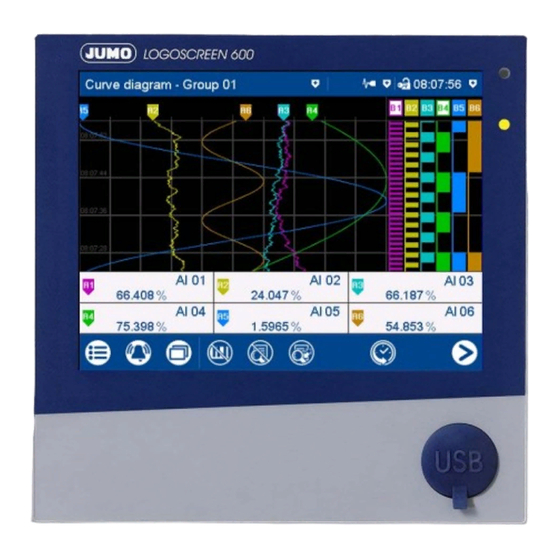
JUMO LOGOSCREEN 600
Paperless Recorder with Touchscreen
Brief Instructions
70652000T97Z001K000
V6.00/EN/00625186
Related Manuals for JUMO LOGOSCREEN 600
Summary of Contents for JUMO LOGOSCREEN 600
-
Page 1
JUMO LOGOSCREEN 600 Paperless Recorder with Touchscreen Brief Instructions 70652000T97Z001K000 V6.00/EN/00625186… -
Page 3: Table Of Contents
Contents Introduction …………7 Safety information .
-
Page 4
Contents 4.4.3 Analog outputs 1 and 2 (options 1 and 2) ……… . 28 4.4.4 Digital inputs/outputs 1 to 12 (option 3) . -
Page 5
Contents 6.1.6 Interfaces …………..74 6.1.7 Screen . -
Page 6
Contents… -
Page 7: Introduction
1 Introduction Safety information 1.1.1 Warning symbols DANGER! This symbol indicates that personal injury caused by electrical shock may occur if the re- spective precautionary measures are not carried out. WARNING! This symbol in connection with the signal word indicates that personal injury may occur if the respective precautionary measures are not carried out.
-
Page 8: Intended Use
1 Introduction 1.1.3 Intended use The device is designed for use as a paperless recorder in an industrial environment as speci- fied in the technical data. Other uses or uses beyond those defined are not viewed as intended uses. The device has been manufactured in compliance with applicable standards and directives as well as applicable safety regulations.
-
Page 9: Acceptance Of Goods, Storage, And Transport
1 Introduction Acceptance of goods, storage, and transport 1.2.1 Checking the delivery • Ensure that the packaging and contents are not damaged • Check that the delivery is complete using the delivery papers and the order details • Inform the supplier immediately if there is any damage •…
-
Page 10: Disposal
1 Introduction CAUTION! Electrostatic charges occur in non-ESD-protected environments. Electrostatic discharges can damage modules or components. For transport purposes, use only the ESD packaging provided. 1.2.4 Disposal Disposing of the device DISPOSAL! Devices and/or replaced parts should not be placed in the refuse bin at the end of their use- ful life as they consist of materials that can be recycled by specialist recycling plants.
-
Page 11: Identifying The Device Version
1 Introduction Identifying the device version 1.3.1 Nameplate The nameplate is affixed to the case. Contents The nameplate contains important information. This includes: Description Description on the name- Example plate Device type Type 706520/18-100-25/260 Part no. 00XXXXXX Serial number F-no. 0070033801215510006 Voltage supply DC 24 V +25/-20 %…
-
Page 12: Order Details
Not used Universal carrying case Compact Subsequent expansion is only possible in JUMO Central Services. This extra code is only available in combination with voltage supply AC 110 to 240 V. The UL approval is not applicable. Use only by technically qualified personnel who are specially trained and have the…
-
Page 13: Scope Of Delivery
1 Introduction (10) Order code Order example 706520 / / 260 , 887 , 970 1.3.3 Scope of delivery 1 paperless recorder in the ordered version 1 brief instructions 4 mounting elements 1 CD with detailed operating manual and supplementary documentation 1.3.4 Accessories Description…
-
Page 14: Content Of The Technical Documentation
1 Introduction Content of the technical documentation The documentation for this device is addressed to equipment manufacturers (OEMs) and users with appropriate technical expertise; it consists of the following documents. 1.4.1 Device documentation in printed form 70652000T97… Brief instructions A hard copy of the brief instructions is part of the scope of delivery of the device. The brief instructions describe the installation, the electrical connection and the operation of the device.
-
Page 15: Device Version
1 Introduction B 709701.0 PC Evaluation Software PCA3000 The operating manual describes the operation and the features of the PC Evaluation Software. The PC Evaluation Software helps to visualize and evaluate the recorded registration data (measurement data, batch data, messages, etc.). B 709702.0 PCA Communications Software PCC The operating manual describes the operation and the features of the PCA Communication…
-
Page 16: Functions Of The Device Version 02
1 Introduction Functions of the device version 02 New functions The following new functions were implemented in device version 02. • Extra code 887 «Manipulation detection with digital certificate»: manipulation detection for the recording data by using a certificate (during saving and transfer) •…
-
Page 17: Description
There are different versions of the JUMO LOGOSCREEN 600 available for process data re- cording. These range from the device version without measuring input in which up to 24 pro-…
-
Page 18: Display And Control Elements
2 Description Display and control elements Touchscreen (TFT color screen) Alarm LED Technical data: The LED is lit while an alarm is pending. Chapter 6.1.7 «Screen», page 74 Power LED The screen appearance is described in The LED flashes after switching on the the «Operation»…
-
Page 19: Installation
3 Installation General information on installation WARNING! The device is not designed for use in potentially explosive areas. There is the risk of an explosion. Only deploy the device outside of potentially explosive areas. Mounting site The device is designed for installation in a panel cut-out. The front of the device and housing have different protection types (see technical data).
-
Page 20: Panel Mounting
3 Installation Panel cut-out Close mounting Distance between panel cut-outs Horizontal Vertical Minimum clearance 20 mm 20 mm Recommended distance (easier installation of fastening elements) 50 mm 50 mm Panel mounting Step Activity Insert the device into the panel cut-out from the front until the seal is flush with the panel. Insert the fastening elements into the recesses of the housing (one element on each cor- ner, see figure) and use a screwdriver to evenly clamp them against the rear side of the panel with a torque of 1.0 Nm.
-
Page 21: Handling The Front Of The Device
3 Installation CAUTION! The front of the device and case have different protection types. The protection type IP65 (front-side) is only guaranteed if the seal is flush and even. The four supplied fastening elements must all be used and distributed evenly as shown in the figure.
-
Page 22
3 Installation Dimensions Intended use The paperless recorder within the carrying case is exclusively intended for use by technically qualified personnel who are specially trained and have the relevant knowledge in the field of automation technology. Cleaning For the cleaning of the carrying case, the same instructions apply as for cleaning the front of the device. -
Page 23: Electrical Connection
4 Electrical connection Installation notes Requirements for personnel • Work on the device must only be carried out to the extent described and, like the electrical connection, only by qualified personnel. • Before plugging and unplugging connecting cables, it must be ensured that the acting per- son is electrostatically discharged (by touching grounded metallic parts, for example).
-
Page 24: Galvanic Isolation
4 Electrical connection Galvanic isolation 50 V 50 V Analog input 1 Analog output 1 50 V 50 V 50 V 50 V Analog input Analog output 3000 V 50 V Relay contact Digital input 1 Digital input 50 V Digital input 50 V…
-
Page 25: Connection Elements
4 Electrical connection Connection elements Front USB host interface (without cover) Back connection elements Connection element and assignment Connection element and assignment USB device interface Ethernet interface RS232/RS485 interface Relay Voltage supply Digital inputs 1 to 6, analog output 1 Analog input 1 Analog input 2 Analog input 3…
-
Page 26: Connection Diagram
4 Electrical connection NOTE! The front-side USB host interface is intended exclusively for connecting a USB flash drive. Any other use is not admissable. NOTE! The quality of the USB cable and the USB flash drive has an influence on the correct function of the device.
-
Page 27
4 Electrical connection Measuring probe Connection element / Assignment Terminals and connection symbol Resistance/potentiometer 7. / Analog input 1 three-wire circuit 8. / Analog input 2 9. / Analog input 3 Resistance/potentiometer 11. / Analog input 4 four-wire circuit 12. / Analog input 5 13. -
Page 28: Digital Inputs 1 To 12 (Options 1 And 2)
4 Electrical connection 4.4.2 Digital inputs 1 to 12 (options 1 and 2) Version Connection element.Terminal / Terminals and connection symbol Assignment 1 2 3 4 5 6 7 8 9 10 Digital input DC 0/24 V, 6.1 / Digital input 1 auxiliary voltage (output) DC 24 V 6.2 / Digital input 2 (50 mA, per option)
-
Page 29: Digital Inputs/Outputs 1 To 12 (Option 3)
4 Electrical connection 4.4.4 Digital inputs/outputs 1 to 12 (option 3) Version Connection element.Terminal / Terminals and connection symbol Assignment 1 2 3 4 5 6 7 8 Digital input DC 0/24 V or 14.1 / Digital input/output 1 digital output DC 0/24 V 14.2 / Digital input/output 2 (individually switchable), 14.3 / Digital input/output 3…
-
Page 30: Rs232/Rs485 Interface
4 Electrical connection 4.4.6 RS232/RS485 interface Version Connection element.Pin / Assign- Connection element ment RS232 3.2 / RxD (received data) 9-pin SUB-D socket 3.3 / TxD (transmission data) (switchable to RS485) 3.5 / GND (ground) RS485 3.3 / TxD+/RxD+ (transmission/ 9-pin SUB-D-socket received data +) (switchable to RS232)
-
Page 31: Operation
5 Operation Operating concept The device is equipped with a resistive touchscreen; the operation is menu-driven. User man- agement protects the device against unauthorized access. The different users can be assigned different privileges so that they can only access specific functions. In addition to the visualizations available per default, the setup program can be used to create individual process screens for presenting process data.
-
Page 32
5 Operation the screen), the batch logging status, and the status of data transmission via the PCC software as a text display. Icons used: Position Meaning Icon Left Data transmission via PCC software — Transmission active — Transmission not active No icon Center Batch recording… -
Page 33: Led Displays
5 Operation The area on the left contains the buttons (icons) for calling up — the main menu (left), — the alarm and event menu (center), and — the visualization menu (right). The area in the center contains buttons (icons) whose function depends on the screen cur- rently being displayed.
-
Page 34: Main Menu
5 Operation Main menu The main menu contains functions for configuring, parameterizing, and operating the device. View Menu items Scroll up Quit main menu Scroll box (current position within the menu); movable Scroll down 5.2.1 Log-In This is the menu in which users log on and off, and change their passwords. The following IDs, names, and passwords are set by default: Users Name…
-
Page 35: Configuration
5 Operation Configuration of the electronic signature: see operating manual, «Configuration – in setup pro- gram only» chapter > «Electronic signature». Example of an electronic signature: Chapter 5.8 «Electronic signature», page 63 5.2.2 Configuration This menu contains functions for configuring the device. The functions are available both on the device and in the setup program (see the «Configuration»…
-
Page 36: Calibrating The Touchscreen
5 Operation 5.2.7 Calibrating the touchscreen This menu enables you to calibrate the touchscreen (position calibration). To do so, you need to tap the center of the crosshairs shown in the corners of the screen one after another. Alarm and event menu The alarm and event menu enables you to call up the alarm list and event list.
-
Page 37: Alarm List
5 Operation 5.3.1 Alarm list The alarm list shows all pending alarms in their order of occurrence. If an alarm is no longer pending, its entry is automatically removed from the alarm list. The alarm list is rebuilt after pow- er on.
-
Page 38: Event List
5 Operation 5.3.2 Event list The event list contains event entries in chronological order. A maximum of 150 entries are stored and displayed. When new entries are added, the oldest entries are deleted. The event list is kept after power off. As with process data, events are transferred to the PC Evaluation Software PCA3000 for eval- uation.
-
Page 39
5 Operation Event list in memory display If the alarm and event menu is called up from the memory display (history) (or from the curve presentation of a completed batch), the event list is opened directly. An additional button is available here which lets you mark the time of a specific event in the memory display with the cursor position. -
Page 40: Visualization Menu (Display)
5 Operation Visualization menu (display) In the visualization menu, the view type and group that should be currently displayed on the device are selected. Up to 6 analog channels and 6 digital channels of a group can be shown on one screen. View Menu items Scroll up…
-
Page 41: Curve Diagram
5 Operation 5.4.1 Curve diagram In the curve diagram, the analog and digital signals configured for the relevant group are dis- played as analog curves or digital traces. Digital traces and channel information can be hidden in the group configuration. The diagram type (horizontal, vertical) is selected individually for each group in the configura- tion.
-
Page 42
5 Operation Memory display (history) Move time for memory values forward Time of memory values (cursor position) (later memory values) Cursor (time of numeric memory values) Zoom factor Move time for memory values back (ear- Navigation bar lier memory values) Analog value at selected time Navigation bar Quit history… -
Page 43
5 Operation Example of an electronic signature: Chapter 5.8 «Electronic signature», page 63 Horizontal diagram In the horizontal diagram, the analog curves and digital traces run from right to left. The channel information is shown on the right edge of the screen; the icons for event and alarm at the top edge of the screen. -
Page 44: Digital Diagram
5 Operation 5.4.2 Digital diagram In the digital diagram, the digital signals configured for the relevant group are displayed as dig- ital traces. The diagram type (horizontal, vertical) is selected individually for each group in the configura- tion. The following view shows the vertical diagram. Accordingly, the description also applies to the horizontal diagram.
-
Page 45: Bar Graph
5 Operation 5.4.3 Bar graph In the bar graph view, the analog signals configured for the relevant group are shown as bar graphs, and the digital signals – depending on their logical state – as colored areas or frames. The diagram type selected for the group (horizontal, vertical) is irrelevant for the bar graph view. The view is always as a column diagram (vertical) and not as a bar diagram (horizontal).
-
Page 46: Text Image
5 Operation 5.4.4 Text image The text image shows the current values for the analog signals configured for the relevant group as numbers. The digital signals – depending on their logical state – are shown as colored areas or frames. Group view Description (pointer) and short analog Digital signal with short signal descrip-…
-
Page 47
5 Operation Individual view Designation (pointer), short signal Bar graph of the analog signal description (configurable), and signal description (configurable) of the analog signal Current value of the analog signal Digital signal with short signal descrip- tion (configurable) and designation (pointer) Back to group view Displays the logical state:… -
Page 48
5 Operation Individual view with alarms Last alarm to have occurred (here: from Limit value for max. alarm (configurable) analog input 03) Current value of analog signal with color Bar graph of analog signal with color change (alarm) change (alarm) Alarm text of analog input Limit value for min. -
Page 49: Report
5 Operation 5.4.5 Report A report shows the statistical information for the relevant group. A report contains the maxi- mum, minimum, and mean values of the analog signals during the recording time (the recording period is configurable). A distinction is made between the current (on-going) report and the completed report.
-
Page 50
5 Operation Detailed view Description (pointer) and short analog Completed report signal description (configurable); report type (configurable; here: external) Time at which the max. value (or min. Current (on-going) report value) occurred Time stamp for current report: beginning Back to previous view of recording and current time Time stamp for completed report: begin- ning and end of reporting period… -
Page 51: Current Batch
5 Operation 5.4.6 Current batch This function opens the protocol for the current batch recording. Batch recording can be started and stopped (depending on the configuration). The protocol layout is defined in the batch configuration. This is where the individual lines of the protocol are defined, and the text for the left column, and content of the right column, are specified (Device: Main menu >…
-
Page 52: Completed Batch
5 Operation 5.4.7 Completed batch This function displays the report for the completed batch recording. Recorded data can be shown as a report and as a curve diagram. If necessary, the report can also display the data from current batch recording. View Open report (statistical information for Open curve presentation (analog curves…
-
Page 53
5 Operation Report for batch Description (pointer) and short analog Data (statistical information) for the signal description (configurable) completed batch recording Go to the next analog signal within the Data (statistical information) for the cur- group rent (on-going) batch recording Back to the batch report view Go to next group … -
Page 54: Process Screen
5 Operation 5.4.8 Process screen This visualization shows the individual process screens. You can use the arrow keys in the nav- igation bar to change to the next process screen. Up to 6 process screens can be created with the setup program and uploaded to the device. For a process screen to be displayed, it must be activated (configuration parameters in the set- up program;…
-
Page 55: Comment Text
5 Operation Detailed view Description (configurable) of the coun- Limit value for max. alarm (configurable) ter/integrator Details of current counter/integrator Bar graph view of the current counter/ integrator The type (configurable; here: external) decides when the status of the counter/ Start and end of the display range are integrator is stored and thus completed.
-
Page 56: Text Input Dialog
5 Operation With a device that has extra code 888 (FDA) the concerned setting is performed with the PCS software. The approach when entering a comment with authentication basically corresponds to the one when rendering an electronic signature for a completed batch (only steps 2 to 4). Example of an electronic signature: …
-
Page 57
5 Operation Text input dialog Parameters (description of the configu- Input box with current text ration parameter from the previous dia- After changing to the text input dialog, log) the current text is fully selected. Tapping on the input box displays a cursor. Tap- ping and dragging the cursor lets you select multiple characters. -
Page 58
5 Operation Keyboard mappings Each of the 30 keys in the default keyboard layout can be mapped with up to 10 characters. The Shift key toggles between the first two characters. To select more characters, you need to hold down the relevant key for longer. This displays a selection window in which you can select the desired character by tapping. -
Page 59: Flash Manager
5 Operation Flash manager The Flash manager menu automatically opens when the device is in basic status and a USB flash drive (FAT16/FAT32 file system) is plugged into the front USB port. If the device is in a menu (main menu, alarm-/event list, display), the Flash manager is opened only after leaving the menu.
-
Page 60
5 Operation plete. Device version 01: When you run the «Writing recording data to USB flash drive» function after this, only the newly-added recorded data is transferred to the USB flash drive. As of device version 02, the user can choose a time period from which the recording data is saved. -
Page 61
5 Operation Save recording data of a certain time period In the following example the recording data of a week should be saved. Select time period Determined starting time (editable) The starting time of the device is automatically determined depending on the current date (here it is: August 11, 2016), the current time (here it is 15:00:00), and the selected time period. -
Page 62: Web Server
5 Operation Web server The device includes a built-in web server which supports online visualization with the help of a web browser. The user can access the process values, various visualizations, and the device’s alarm and event list. For access, you need to enter the device’s IP address in the address line of the web browser. If needed, you can also use the DNS device name.
-
Page 63: Electronic Signature
5 Operation Electronic signature As of device version 02 and with extra code 888 (FDA), the user has the option to provide a completed batch or the recording data of a certain time period with his/her electronic signature. A logged-on user can provide his/her signature during logoff – it applies to the entire time period for which the user was signed in.
-
Page 64
5 Operation Step Activity Select your user ID (in this case: Master) The user has to select his/her ID. This step is required because someone other than the currently logged-on user can provide this signature. Enter text that describes the meaning of the signature (evaluation text) using the keyboard. Alternatively, select text from the text list (1) and, if required, edit it: The possibilities of entering a text depend on the configuration (no text available, enter text via keyboard, select text from text list, select text from text list and edit). -
Page 65
5 Operation Step Activity Enter password: Confirm process: The process can be still be aborted here. -
Page 66
5 Operation Step Activity In the protocol of a completed batch recording press the button (1) to display the provided signature: ➥ The signature (here: Master) and the meaning of the signature (here: Batch o.k.) are dis- played. -
Page 67
5 Operation Time period The electronic signature for a time period essentially differs from the signature for the complet- ed batch by requiring the time period in question to be selected. The signature applies to the time period that is displayed in the diagram at the time of the sig- nature. -
Page 68
5 Operation… -
Page 69: Annex
6 Annex Technical data 6.1.1 Analog inputs (options 1 and 2) General information Quantity 0, 3, or 6 Connector number (back of 7 to 9, 11 to 13 device) Thermocouples Description Standard Measuring range Accuracy ≤ 0.25 % Fe-CuNi «L» DIN 43710 ITPS-68 -200 to +900 °C…
-
Page 70
6 Annex RTD temperature probe Description Standard Connection Measuring range Accuracy Measur- type ing cur- rent ≤ 0.1 % 500 μA Pt50 IEC 751: 2008 ITS-90 2-/3-/4-wire -200 to +850 °C ≤ 0.1 % 500 μA Pt100 IEC 751: 2008 ITS-90 2-/3-/4-wire -200 to +850 °C… -
Page 71
6 Annex Resistance transmitter and resistor/potentiometer Description Measuring range Accuracy Measuring current 0 to 4000 Ω ≤ 0.1 % 100 μA Resistance transmitter 0 to 400 Ω ≤ 0.1 % 500 μA Resistance/potentiometer 0 to 4000 Ω ≤ 0.1 % 100 μA ≤… -
Page 72: Digital Inputs (Options 1 And 2)
6 Annex Measuring circuit monitoring The device response in the event of a fault is configurable. Measuring probe Probe break Short-circuit Polarity Thermocouple is detected is not detected is detected in certain conditions RTD temperature probe is detected is detected is not detected Resistance transmitter is detected…
-
Page 73: Digital Inputs/Outputs (Option 3)
6 Annex 6.1.3 Digital inputs/outputs (option 3) Quantity 0 or 12 Connector number (back of 14 and 15 device) Input or output Individually configurable as input or output Input Logic level «0»: < 3.5 V; logic level «1»: > 10 V Level Sampling rate 125 ms (max.
-
Page 74: Interfaces
6 Annex 6.1.6 Interfaces RS232/RS485 Quantity 1 (can be switched between RS232 and RS485) Connector type SUB-D 9-pin (socket) Baud rate 9600, 19200, 38400, 115200 Data format 8/1n, 8/1e, 8/1o Protocol Modbus RTU as master or slave; barcode scanner Application Communication with Modbus master/slave, connection of a barcode scanner External inputs Via Modbus master/slave functionality: 24 analog and 24 digital inputs, 10 batch…
-
Page 75: Electrical Data
6 Annex 6.1.8 Electrical data Voltage supply AC 110 to 240 V +10/-15 %, 48 to 63 Hz or AC/DC 20 to 30 V, 48 to 63 Hz (not in conjunction with extra code 970) Electrical safety According to DIN EN 61010-1 Overvoltage category II up to 300 V mains voltage, pollution degree 2 Protection rating I with internal isolation from SELV…
-
Page 76: Environmental Influences
6 Annex 6.1.9 Environmental influences Ambient temperature range Storage -20 to +60 °C Operation 0 to +50 °C; in conjunction with extra code 970: 0 to +40 °C Site altitude Up to 2000 m above sea level Climatic environmental conditions According to DIN EN 60721-3 with extended temperature range ≤…
-
Page 77: Change Of The Buffer Battery
6 Annex Change of the buffer battery CAUTION! The device contains a buffer battery that is used for data buffering when the device is in switched off mode or if the power fails. The life of the battery is at least 7 years. A low battery is indicated by the battery pre-alarm («Battery low»).
-
Page 78: China Rohs
6 Annex China RoHS…
-
Page 79: Barcode
6 Annex Barcode Initialize the barcode scanner The barcode scanner must be initialized once before use. Example: Step Activity Scan the „Factory Default Settings“ barcode. Scan the „RS-232 Standard“ barcode („Select RS-232 Standard“). Information and bar codes can be found in the manual of the barcode scanner used. 6.4.1 Batch control NOTE!
-
Page 80
6 Annex Reset the texts Step Activity Scan the RESET barcode. RESET The entered batch texts are reset. The default texts are shown and the first line is prepared again for the text input. The default text is defined in the configuration of the batch line (Configuration > Batch > Batch line: Default text). -
Page 81: Enter Event Texts And Process Values
6 Annex 6.4.2 Enter event texts and process values As of device version 02 an event text or process value (external text/analog/digital variables) can be entered by means of specific control characters. The text or value, which is scanned using a control character, is exclusively used as event text or process value.
-
Page 82
6 Annex Enter Boolean value in external digital variable: %Bn% = enter as Boolean value into the external digital variable n (n = 1 to 24) Example: %B1%1 %B 1 %1 The Boolean value 1 (TRUE) is entered into the external digital variable 1. The entered value is available in the digital selector. -
Page 84
JUMO GmbH & Co. KG JUMO Instrument Co. Ltd. JUMO Process Control, Inc. Street address: JUMO House 6733 Myers Road Moritz-Juchheim-Straße 1 Temple Bank, Riverway East Syracuse, NY 13057, USA 36039 Fulda, Germany Harlow, Essex CM 20 2DY, UK Phone:…
Contents
4.4.5 Relay . . . . . . . . . . . . . . . . . . . . . . . . . . . . . . . . . . . . . . . . . . . . . . . . . . . . . . . . . . . . . . . . . . . . . . 29
4.4.6 RS232/RS485 interface . . . . . . . . . . . . . . . . . . . . . . . . . . . . . . . . . . . . . . . . . . . . . . . . . . . . . . . . 30
4.4.7 Voltage supply . . . . . . . . . . . . . . . . . . . . . . . . . . . . . . . . . . . . . . . . . . . . . . . . . . . . . . . . . . . . . . . 30
5
Operation . . . . . . . . . . . . . . . . . . . . . . . . . . . . . . . . . . . . . . . . . . . . . . . . . . . . . . .31
5.1
Operating concept . . . . . . . . . . . . . . . . . . . . . . . . . . . . . . . . . . . . . . . . . . . . . . . . . . . . . . . . . . . . 31
5.1.1 Touchscreen . . . . . . . . . . . . . . . . . . . . . . . . . . . . . . . . . . . . . . . . . . . . . . . . . . . . . . . . . . . . . . . . 31
5.1.2 LED displays . . . . . . . . . . . . . . . . . . . . . . . . . . . . . . . . . . . . . . . . . . . . . . . . . . . . . . . . . . . . . . . . 33
5.2
Main menu . . . . . . . . . . . . . . . . . . . . . . . . . . . . . . . . . . . . . . . . . . . . . . . . . . . . . . . . . . . . . . . . . . 34
5.2.1 Log-In . . . . . . . . . . . . . . . . . . . . . . . . . . . . . . . . . . . . . . . . . . . . . . . . . . . . . . . . . . . . . . . . . . . . . 34
5.2.2 Configuration . . . . . . . . . . . . . . . . . . . . . . . . . . . . . . . . . . . . . . . . . . . . . . . . . . . . . . . . . . . . . . . . 35
5.2.3 Parameterization . . . . . . . . . . . . . . . . . . . . . . . . . . . . . . . . . . . . . . . . . . . . . . . . . . . . . . . . . . . . . 35
5.2.4 Device info . . . . . . . . . . . . . . . . . . . . . . . . . . . . . . . . . . . . . . . . . . . . . . . . . . . . . . . . . . . . . . . . . . 35
5.2.5 Audit trail list . . . . . . . . . . . . . . . . . . . . . . . . . . . . . . . . . . . . . . . . . . . . . . . . . . . . . . . . . . . . . . . . 35
5.2.6 Service . . . . . . . . . . . . . . . . . . . . . . . . . . . . . . . . . . . . . . . . . . . . . . . . . . . . . . . . . . . . . . . . . . . . 35
5.2.7 Calibrating the touchscreen . . . . . . . . . . . . . . . . . . . . . . . . . . . . . . . . . . . . . . . . . . . . . . . . . . . . . 36
5.3
Alarm and event menu . . . . . . . . . . . . . . . . . . . . . . . . . . . . . . . . . . . . . . . . . . . . . . . . . . . . . . . . 36
5.3.1 Alarm list . . . . . . . . . . . . . . . . . . . . . . . . . . . . . . . . . . . . . . . . . . . . . . . . . . . . . . . . . . . . . . . . . . . 37
5.3.2 Event list . . . . . . . . . . . . . . . . . . . . . . . . . . . . . . . . . . . . . . . . . . . . . . . . . . . . . . . . . . . . . . . . . . . 38
5.4
Visualization menu (display) . . . . . . . . . . . . . . . . . . . . . . . . . . . . . . . . . . . . . . . . . . . . . . . . . . . . 40
5.4.1 Curve diagram . . . . . . . . . . . . . . . . . . . . . . . . . . . . . . . . . . . . . . . . . . . . . . . . . . . . . . . . . . . . . . . 41
5.4.2 Digital diagram . . . . . . . . . . . . . . . . . . . . . . . . . . . . . . . . . . . . . . . . . . . . . . . . . . . . . . . . . . . . . . 44
5.4.3 Bar graph . . . . . . . . . . . . . . . . . . . . . . . . . . . . . . . . . . . . . . . . . . . . . . . . . . . . . . . . . . . . . . . . . . . 45
5.4.4 Text image . . . . . . . . . . . . . . . . . . . . . . . . . . . . . . . . . . . . . . . . . . . . . . . . . . . . . . . . . . . . . . . . . . 46
5.4.5 Report . . . . . . . . . . . . . . . . . . . . . . . . . . . . . . . . . . . . . . . . . . . . . . . . . . . . . . . . . . . . . . . . . . . . . 49
5.4.6 Current batch . . . . . . . . . . . . . . . . . . . . . . . . . . . . . . . . . . . . . . . . . . . . . . . . . . . . . . . . . . . . . . . . 51
5.4.7 Completed batch . . . . . . . . . . . . . . . . . . . . . . . . . . . . . . . . . . . . . . . . . . . . . . . . . . . . . . . . . . . . . 52
5.4.8 Process screen . . . . . . . . . . . . . . . . . . . . . . . . . . . . . . . . . . . . . . . . . . . . . . . . . . . . . . . . . . . . . . 54
5.4.9 Counter/Integrator . . . . . . . . . . . . . . . . . . . . . . . . . . . . . . . . . . . . . . . . . . . . . . . . . . . . . . . . . . . . 54
5.4.10 Comment text . . . . . . . . . . . . . . . . . . . . . . . . . . . . . . . . . . . . . . . . . . . . . . . . . . . . . . . . . . . . . . . 55
5.5
Text input dialog . . . . . . . . . . . . . . . . . . . . . . . . . . . . . . . . . . . . . . . . . . . . . . . . . . . . . . . . . . . . . 56
5.6
Flash manager . . . . . . . . . . . . . . . . . . . . . . . . . . . . . . . . . . . . . . . . . . . . . . . . . . . . . . . . . . . . . . 59
5.7
Web server . . . . . . . . . . . . . . . . . . . . . . . . . . . . . . . . . . . . . . . . . . . . . . . . . . . . . . . . . . . . . . . . . 62
5.8
Electronic signature . . . . . . . . . . . . . . . . . . . . . . . . . . . . . . . . . . . . . . . . . . . . . . . . . . . . . . . . . . . 63
6
Annex . . . . . . . . . . . . . . . . . . . . . . . . . . . . . . . . . . . . . . . . . . . . . . . . . . . . . . . . . .69
6.1
Technical data . . . . . . . . . . . . . . . . . . . . . . . . . . . . . . . . . . . . . . . . . . . . . . . . . . . . . . . . . . . . . . . 69
6.1.5 Relay . . . . . . . . . . . . . . . . . . . . . . . . . . . . . . . . . . . . . . . . . . . . . . . . . . . . . . . . . . . . . . . . . . . . . . 73
4

cf
Экранный регистратор
B 70.6510.0
Инструкция по эксплуатации
05.06 / 00467981
Note for Owners:
Guidesimo.com webproject is not a service center of JUMO trademark and does not carries out works for diagnosis and repair of faulty JUMO LOGOSCREEN 600 equipment. For quality services, please contact an official service center of JUMO company. On our website you can read and download documentation for your JUMO LOGOSCREEN 600 device for free and familiarize yourself with the technical specifications of device.
-
JVC HR-A37U
SPECIFICATIONS (The specifications shown pertain specifically to the model HR-A57U/A37U)SERVICE MANUALNo.82836December 2000HR-A37UVIDEO CASSETTE RECORDERSpecif ications shown are for SP mode unless specified otherwise.E. & O.E. Design and specifications subject to change without notice.Frequency range[HR-A57U]Normal audio : 70 Hz to 10,000 HzHi-Fi audio : 20 Hz to 20,000 Hz[HR-A37U]Normal au …
HR-A37U Recording Equipment, 38
-
WMG C29
Recorder Instruction ManualPlease read the manual before using it.Statement:1. First, thanks for using our company’s digital products!2. Please read the manual before using for the proper use of it.3. As for the information, please back up on your own. Our company takes no responsibility to any loss of data caused by abnormal operation of software, hardware, or produ …
C29 Voice Recorder, 9
-
RCA RP5012
AUDIORP5012Digital Voice Recorderwith 16MB Built-InMemory• 16MB Built-In Flash Memory• Up to 6 Hours of Record Time• Multifunctional LCD Display• Automatic Voice Activated Recording (AVR)• 4 Folders with Maximum of 200 Files• Date/Time Stamp• Message Editing• Real Time Clock• Built-In Microphone• Built-In Speaker• Low Battery Indicator• 1-Year Limited Warranty*• Accessor …
RP5012 Voice Recorder, 2
-
Olympus S701 — Pearlcorder Microcassette Dictaphone
CÂMARA DIGITALSTYLUS-7020/µ-7020STYLUS-7010/µ-7010● ObrigadoporteradquiridoumacâmaradigitalOlympus.Antesdeutilizarasuanovacâmara,leiaatentamenteestemanualdemodoausufruirdeumexcelentedesempenhodasuacâmaraedeumaduraçãoprolongada.Mantenhaestemanualnumlocalseguropara� …
S701 — Pearlcorder Microcassette Dictaphone Voice Recorder, 72
-
Fostex D-108
D-108 & D-160v28- and 16-Track Removable Hard Disk Recorder/Editors• 8- or 16-track Recording with 8 Virtual Tracks.• Removable 2.55gb Hard DriveOffers 1/2-hour of recording on 16 tracksor 1 full hour on 8 tracks, plus simultane-ous 8-track analog + 8-track digitalrecording. Upgradable to up to an 8gb HDfor 1.5 hours of 16-track recording.• ADAT™ InterfaceSingle (D-108) or dual ( …
D-108 DVR, 1
-
Sylvania DVR90VG
SERVICE MANUALMain SectionI SpecificationsI Preparation for ServicingI Adjustment ProceduresI Schematic DiagramsI CBA’sI Exploded ViewsI Parts ListWhen servicing the deck mechanism, refer to MK14 Deck Mechanism Section.Deck Mechanism Part No.: N2460FLDVD RECORDER & VIDEO CASSETTE RECORDERDVR90VG …
DVR90VG Voice Recorder, 83
-
Philips DVR5100
High De nition Digital Video Recorder DVR5100DVR7100Quick Start GuideConnectSet upEnjoy123What’s in the box?Digital Video RecorderRF antenna cable (connect between recorder and TV)Remote Controland 2 batteriesUser ManualComponentvideo cableAudio/VideocableAntenna interconnected cableStart RecordingA Recording the programme you are watchingA Press P +/- to scroll through the channels that you …
DVR5100 DVR, 2
-
Zoom H2next
MOORLANDS: PEOPLE, PLACES, STORIES Guidance Sheet C (V2) Quick Guide to using the Zoom H2next Handy Recorder The user manual is available to download from the Zoom-uk website: www.zoom-uk.com/products/field-video-recording/field-recording/zoom-h2n-handy-recorder#downloads Microphone Setting Dial To record 1. Turn on by sliding the ‘Hold/Power’ button at the bottom of the right ha …
H2next Voice Recorder, 2
-
Sony ICD-BM1B — Memory Stick Media Digital Voice Recorder
ICD-BM1AMemory Stick® Media Digital Voice Recorder Step-up Slide Control Switch OperationHigh Value Design with Seamless Aluminum BodyUses Removable Memory Stick® Media-Includes One 32MB Memory Stick1 Up to 694 Minutes Recording Time with Supplied 32MB Memory Stick3 USBConnectivity for High Speed Copying of Files to the PC2 Selective Automatic Folder Copy Function to the PCCompatible with …
ICD-BM1B — Memory Stick Media Digital Voice Recorder Voice Recorder, 2
Popular Voice Recorder User Guides:

Краткие характеристики:
Экранный регистратор данных LOGOSCREEN 600 оснащен резистивным сенсорным экраном и отличается удобством обслуживания благодаря интуитивно понятной, использующей простые символы, концепции управления и визуализации.
Регистратор LOGOSCREEN 600 предназначен для регистрации параметров процесса и доступен в различных вариантах исполнения: от устройств без измерительных входов, у которых до 24 параметров могут считываться (ведущее устройство) или приниматься (ведомое устройство) по протоколу Modbus с внешних систем, до моделей с 6 измерительными входами (универсальные аналоговые входы), 2 аналоговыми выходами, 12 цифровыми входами и 12 переключаемыми по отдельности цифровыми входами, выходами.
В регистраторе LOGOSCREEN 600 данные могут отображаться в соответствии с заводской настройкой визуализации, например в виде кривой (вертикальной или горизонтальной), гистограммы, в текстовом виде (численИли отправьте нам запрос нафровой диаграммы. Для циклических технологических процессов доступна специальная регистрация циклов, позволяющая записывать в память дополнительную информацию. Дополнительно пользователь с помощью программы установки может создавать до 6 окон процессов с индивидуальными настройками, соответствующими его требованиям, включающих в себя до 100 объектов отображения. Наряду с Setup-программой, обеспечивающей быструю настройку прибора через компьютер, доступны также две удобные компьютерные программы для считывания, архивирования и анализа параметров процесса (РСС и РСА3000).
По вопросу интересующей Вас продукции, пожалуйста, свяжитесь с нами:
Или отправьте нам запрос на e-mail: zapros@filfar.by
![]()