-
Contents
-
Table of Contents
-
Bookmarks
Quick Links
K9N Neo V2/ V3 Series
MS-7369 (V1.X) Mainboard
G52-73691X1
i
Related Manuals for MSI K9N Neo V2 Series
Summary of Contents for MSI K9N Neo V2 Series
-
Page 1
K9N Neo V2/ V3 Series MS-7369 (V1.X) Mainboard G52-73691X1… -
Page 2: Copyright Notice
Alternatively, please try the following help resources for further guidance. Visit the MSI website for FAQ, technical guide, BIOS updates, driver updates, an d ot h er i n f orm at i on: h t t p: / / g l o ba l .
-
Page 3: Safety Instructions
Safety Instructions Always read the safety instructions carefully. Keep this User’s Manual for future reference. Keep this equipment away from humidity. Lay this equipment on a reliable flat surface before setting it up. The openings on the enclosure are for air convection hence protects the equip- ment from overheating.
-
Page 4: Fcc-B Radio Frequency Interference Statement
FCC-B Radio Frequency Interference Statement T h is eq uip men t h as been tested and found to c omply with the limits for a Class B digital device, pursuant to Part 15 of the FCC Rules. These limits are designed to provide reasonable protection against harmful interference in a residential installation.
-
Page 5: Weee (Waste Electrical And Electronic Equipment) Statement
WEEE (Waste Electrical and Electronic Equipment) Statement…
-
Page 8: Table Of Contents
CONTENTS Copyright Notice ………………….ii Trademarks ……………………ii Revision History ………………….ii Technical Support ………………….ii Safety Instructions ………………….iii FCC-B Radio Frequency Interference Statement …………iv W EEE (Waste Electrical and Electronic Equipment) Statement ……..v Chapter 1 Getting Started ………………1-1 Mainboard Specifications ……………….
-
Page 9
Appendix B nVidia RAID ………………B-1 Introduction ………………….B-2 RAID Configuration ………………..B-3 NVIDIA RAID Utility Installation …………….B-9 RAID Drives Management ……………… B-12 Appendix C nVidia System Driver …………..C-1 nVidia System Driver Installation ……………. C-2 nVidia Utility Installaion ………………C-5 Appendix D Dual Core Center ……………. -
Page 10: Chapter 1 Getting Started
Getting Started Chapter 1 Getting Started Thank you for choosing the K9N Neo V2/ V3 Series (MS-7369 v1.X) ATX mainboard. The K9N Neo V2/ V3 ® Series mainboards are based on nVidia nForce 520/ nForce 560 single chipset for optimal system efficiency. ®…
-
Page 11: Mainboard Specifications
Mainboard Specifications Processor Support ® — AMD Athlon 64/ 64X2 & Sempron in the socket AM2 package (For the latest information about CPU, please visit http://global.msi. com.tw/index.php?func=cpuform) Supported FSB — HyperTransport supporting speed up to 1 GHz (2000MT/s) Chipset ®…
-
Page 12
Getting Started Floppy — 1 floppy port — Supports 1 FDD with 360KB, 720KB, 1.2MB, 1.44MB and 2.88MB Connectors Back panel — 1 PS/2 mouse port — 1 PS/2 keyboard port — 1 Serial port — 1 Parallel port support SPP/EPP/ECP mode — 4 USB 2.0 Ports — 1 LAN jack — 6 audio jacks… -
Page 13: Mainboard Layout
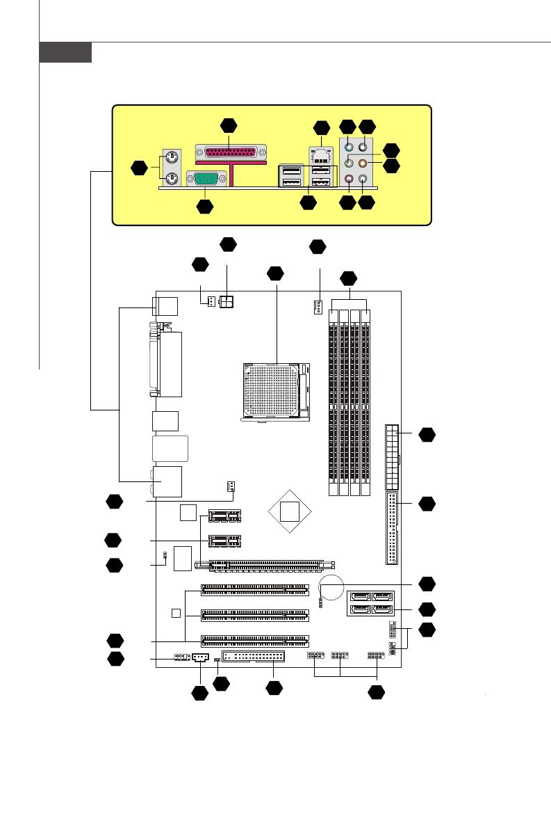
M S-7369 M ainboard Mainboard Layout CPUFAN1 Top : mouse Bottom: SYSFAN2 JPW1 keyboard Top : Parallel Port Bottom: COM portA USB ports Top: LAN Jack Bottom: USB ports Line-In Line-Out SYSFAN1 T:RS-Out M:CS-Out B:SS-Out nForce 520/ nForce 560 Chip PCI_E2 PCI_E1 JCI1…
-
Page 14: Packing Checklist
Getting Started Packing Checklist Standard Cable for MSI Driver/Utility CD IDE Devices (Optional) MSI motherboard Back IO Shield SATA Cable Power Cable User’s Guide * The pictures are for reference only and may vary from the packing contents of the…
-
Page 15: Chapter 2 Hardware Setup
Hardware Setup Chapter 2 Hardware Setup This chapter provides you with the information about hardware setup procedures. While doing the installation, be careful in holding the components and follow the installation procedures. For some components, if you install in the wrong orientation, the components will not work properly.
-
Page 16: Quick Components Guide
M S-7369 M ainboard Quick Components Guide SYSFAN2, CPU, p.2-3 p.2-14 DDR2 DIMMs, p.2-6 JPW1, CPUFAN1, p.2-8 p.2-14 SYSFAN1, p.2-14 Back Panel I/O, p.2-10 ATX1, p.2-8 IDE1, p.2-12 PCIE x1 slot, p.2-19 JCI1, p.2-14 PCIE x16 slot, JBAT1, p.2-18 p.2-19 SATA1~4, p.2-13 JFP1, p.2-17…
-
Page 17: Cpu (Central Processing Unit)
If you do not have the heat sink and cooling fan, contact your dealer to purchase and install them before turning on the computer. For the latest information about CPU, please visit http://global.msi.com.tw/index.php? func=cpuform Important Overheating Overheating will seriously damage the CPU and system.
-
Page 18: Cpu Installation Procedures For Socket Am2
M S-7369 M ainboard CPU Installation Procedures for Socket AM2 1. Please turn off the power and unplug the power cord before Open Lever installing the CPU. Sliding 2. Pull the lever s ideways away 90 degree Plate from the socket. Make sure to raise the lever up to a 90-de- gree angle.
-
Page 19: Installing Amd Socket Am2 Cpu Cooler Set
Hardware Setup Installing AMD Socket AM2 CPU Cooler Set W hen you are installing the CPU, make sure the CPU has a heat sink and a cooling fan attached on the top to prevent overheating. If you do not have the heat sink and cooling fan, contact your dealer to purchase and install them before turning on the computer.
-
Page 20: Memory
M S-7369 M ainboard Memory These DIMM slots are used for installing memory modules. For more information on compatible components, please visit http://global.msi.com. tw/index.php?func=testreport DDR2 240-pin, 1.8V 56×2=112 pin 64×2=128 pin Dual-Channel mode Population Rule In Dual-Channel mode, the memory modules can transmit and receive data with two data bus lines simultaneously.
-
Page 21: Installing Memory Modules
Hardware Setup Installing Memory Modules 1. The memory module has only one notch on the center and will only fit in the right orientation. 2. Insert the memory module vertically into the DIMM slot. Then push it in until the golden finger on the memory module is deeply inserted in the DIMM slot.
-
Page 22: Power Supply
M S-7369 M ainboard Power Supply ATX 24-Pin Power Connector: ATX1 This connector allows you to connect an ATX 24-pin power supply. pin 13 To connect the ATX 24-pin power supply, make sure the plug of the power supply is inserted in the proper orientation and the pins are aligned.
-
Page 23: Important Notification About Power Issue
Hardware Setup Important Notification about Power Issue NForce chipset is very sensitive to ESD (Electrostatic Discharge), therefore this issue mostly happens while the users intensively swap memory modules under S5 (power-off) states, and the power code is plugged while installing modules. Due to several pins are very sensitive to ESD, so this kind of memory-replacement actions might cause system chipset unable to boot.
-
Page 24: Back Panel
M S-7369 M ainboard Back Panel Parallel Port Mouse Line-In RS-Out Line-Out CS-Out SS-Out USB Port USB Port Keyboard Serial Port M ouse/Keyboard Connector ® ® The standard PS/2 mouse/keyboard DIN connector is for a PS/2 mouse/keyboard. Parallel Port Connector A parallel port is a standard printer port that supports Enhanced Parallel Port (EPP) and Extended Capabilities Parallel Port (ECP) mode.
-
Page 25
Hardware Setup USB Port The USB (Universal Serial Bus) port is for attaching USB devices such as keyboard, mouse, or other USB-compatible devices. Audio Ports These audio connectors are used for audio devices. You can differentiate the color of the audio jacks for different audio sound effects. Line-In (Blue) — Line In, is used for external CD player, tapeplayer or other audio devices. -
Page 26: Floppy Disk Drive Connector
M S-7369 M ainboard Connectors Floppy Disk Drive Connector: FDD1 This connector supports 360KB, 720KB, 1.2MB, 1.44MB or 2.88MB floppy disk drive. FDD1 IDE Connector: IDE1 This connector supports IDE hard disk drives, optical disk drives and other IDE devices. IDE1 Important If you install two IDE devices on the same cable, you must configure the…
-
Page 27
Hardware Setup Serial ATA Connector: SATA1/ SATA2/ SATA3/ SATA4 This connector is a high-speed Serial ATA interface port. Each connector can con- nect to one Serial ATA device. SATA2 SATA4 SATA1 SATA3 Important Please do not fold the Serial ATA cable into 90-degree angle. Otherwise, data loss may occur during transmission. -
Page 28
M S-7369 M ainboard Fan Power Connectors: CPUFAN1, SYSFAN1, SYSFAN2 The fan power connectors support system cooling fan with +12V. W hen connecting the wire to the connectors, always note that the red wire is the positive and should be connected to the +12V; the black wire is Ground and should be connected to GND. If the mainboard has a System Hardware Monitor chipset on-board, you must use a specially designed fan with speed sensor to take advantage of the CPU fan control. -
Page 29
Hardware Setup Front Panel Audio Connector: JAUD1 This connector allows you to connect the front panel audio and is compliant with ® Intel Front Panel I/O Connectivity Design Guide. JAUD1 HD Audio Pin Definition SIGNAL DESCRIPTION MIC_L Microphone — Left channel Ground MIC_R Microphone — Right channel… -
Page 30: Front Usb Connector
M S-7369 M ainboard Front USB Connector: JUSB1 / JUSB2 / JUSB3 ® This connector, compliant with Intel I/O Connectivity Design Guide, is ideal for con- necting high-speed USB interface peripherals such as USB HDD, digital cameras, M P3 players, printers, modems and the like. Pin Definition SIGNAL SIGNAL…
-
Page 31: Front Panel Connectors
Hardware Setup Front Panel Connectors: JFP1, JFP2 These connectors are for electrical connection to the front panel switches and LEDs. ® The JFP1 is compliant with Intel Front Panel I/O Connectivity Design Guide. Power Power Switch JFP1 Reset Switch JFP1 Pin Definition SIGNAL DESCRIPTION HD_LED +…
-
Page 32: Jumper
M S-7369 M ainboard Jumper Clear CMOS Jumper: JBAT1 There is a CMOS RAM onboard that has a power supply from an external battery to keep the data of system configuration. W ith the CMOS RAM, the system can auto- matically boot OS every time it is turned on.
-
Page 33: Slots
Hardware Setup Slots PCI (Peripheral Component Interconnect) Express Slot The PCI Express slot supports the PCI Express interface expansion card. The PCI Express x 16 supports up to 4.0 GB/s transfer rate. The PCI Express x 8 supports up to 2.0 GB/s transfer rate. The PCI Express x 4 supports up to 1.0 GB/s transfer rate.
-
Page 34: Chapter 3 Bios Setup
BIOS Setup Chapter 3 BIOS Setup This chapter provides information on the BIOS Setup program and allows you to configure the system for optimum use. You may need to run the Setup program when: ² An error message appears on the screen during the system booting up, and requests you to run SETUP.
-
Page 35: Entering Setup
M S-7369 M ainboard Entering Setup Power on the computer and the system will start POST (Power On Self Test) process. W hen the message below appears on the screen, press <DEL> key to enter Setup. Press DEL to enter SETUP If the message disappears before you respond and you still wish to enter Setup, restart the system by turning it OFF and On or pressing the RESET button.
-
Page 36: Control Keys
BIOS Setup Control Keys < ↑> Move to the previous item < ↓> Move to the next item < ←> Move to the item in the left hand < →> Move to the item in the right hand <Enter> Select the item <Esc>…
-
Page 37: The Main Menu
M S-7369 M ainboard The Main Menu Standard CM OS Features Use this menu for basic system configurations, such as time, date etc. Advanced BIOS Features ® Use this menu to setup the items of AMI special enhanced features. Integrated Peripherals Use this menu to specify your settings for integrated peripherals.
-
Page 38
BIOS Setup Load Optimized Defaults Use this menu to load the default values set by the mainboard manufacturer specifi- cally for optimal performance of the mainboard. BIOS Setting Password Use this menu to set the password for BIOS. Save & Exit Setup Save changes to CMOS and exit setup. -
Page 39: Standard Cmos Features
M S-7369 M ainboard Standard CMOS Features The items in Standard CMOS Features Menu includes some basic setup items. Use the arrow keys to highlight the item and then use the <PgUp> or <PgDn> keys to select the value you want in each item. Date (MM:DD:YY) This allows you to set the system to the date that you want (usually the current date).
-
Page 40
BIOS Setup Device/ Vendor/ Size It will showing the device information that you connected to the IDE/SATA connectors. LBA/Large M ode This allows you to enable or disable the LBA Mode. Setting to Auto enables LBA mode if the device supports it and the devices is not already formatted with LBA mode disabled. -
Page 41: Advanced Bios Features
M S-7369 M ainboard Advanced BIOS Features Boot Sector Protection This function protects the BIOS from accidental corruption by unauthorized users or computer viruses. W hen enabled, the BIOS’ data cannot be changed when attempt- ing to update the BIOS with a Flash utility. To successfully update the BIOS, you’ll need to disable this Flash BIOS Protection function.
-
Page 42
BIOS Setup MPS Table Version This field allows you to select which MPS (Multi-Processor Specification) version to be used for the operating system. You need to select the MPS version supported by your operating system. To find out which version to use, consult the vendor of your operating system. -
Page 43: Integrated Peripherals
M S-7369 M ainboard Integrated Peripherals USB Controller This setting allows you to enable/disable the onboard USB controller. USB Device Legacy Support Select [Enabled] if you need to use a USB-interfaced device in the operating system. Onboard LAN Controller This item is used to enable/disable the onboard LAN controller. LAN Option ROM This item is used to decide whether to invoke the Boot ROM of the LAN controller.
-
Page 44
BIOS Setup On-Chip IDE Controller This item allows you to enable/ disable the IDE controller. PCI IDE BusMaster This item allows you to enable/ disable BIOS to used PCI busmastering for reading/ writing to IDE drives. On-Chip SATA Controller This item allows you to enable/ disable the SATA controller. RAID mode Select [RAID] will enable RAID function. -
Page 45: Power Management Setup
M S-7369 M ainboard Power Management Setup Important S3-related functions described in this section are available only when your BIOS supports S3 sleep mode. ACPI Function This item is to activate the ACPI (Advanced Configuration and Power Management Interface) Function. If your operating system is ACPI-aware, such as W indows 2000/ XP, select [Enabled].
-
Page 46
BIOS Setup Power Button Function This feature sets the function of the power button. Settings are: [Power Off] The power button functions as normal power off button. [Suspend] W hen you press the power button, the computer enters the suspend/sleep mode, but if the button is pressed for more than four seconds, the computer is turned off. -
Page 47: Pnp/Pci Configurations
M S-7369 M ainboard PNP/PCI Configurations This section describes configuring the PCI bus system and PnP (Plug & Play) feature. PCI, or Peripheral Component Interconnect, is a system which allows I/O devices to operate at speeds nearing the speed the CPU itself uses when communicating with its special components.
-
Page 48
BIOS Setup IRQ Resource Setup Press <Enter> to enter the sub-menu and the following screen appears. IRQ 3/4/5/7/9/10/11/14/15 These items specify the bus where the specified IRQ line is used. The settings determine if AMIBIOS should remove an IRQ from the pool of avail- able IRQs passed to devices that are configurable by the system BIOS. -
Page 49: H/W Monitor
M S-7369 M ainboard H/W Monitor Chassis Intrusion The field enables or disables the feature of recording the chassis intrusion status and issuing a warning message if the chassis is once opened. To clear the warning message, set the field to [Reset]. The setting of the field will automatically return to [Enabled] later.
-
Page 50: Frequency/Voltage Control
BIOS Setup Frequency/Voltage Control Current CPU/ DRAM Frequency These items show the current clocks of CPU and Memory speed. Read-only. AMD Cool’n’Quiet The Cool’n’ Quiet technology can effectively and dynamically lower CPU speed and power consumption. Important To ensure that Cool’n’Quiet function is ac- tivated and will be working properly, it is required to double confirm that: 1.
-
Page 51
M S-7369 M ainboard Important Change these settings only if you are familiar with the chipset. Adjust CPU FSB Frequency This item allows you to select the CPU Front Side Bus clock frequency (in MHz). Adjust CPU Ratio This item allows you to set the CPU ratio. Advance DRAM Configuration Press <Enter>… -
Page 52
BIOS Setup ROW to ROW Delay (TRRD) W hen the MCT Timing Mode sets to [Manual], the field is adjustable. Specifies the active-to-active delay of different banks. ROW Cycle Time (TRC) W hen the MCT Timing Mode sets to [Manual], the field is adjustable. The row cycle time determines the minimum number of clock cycles a memory row takes to complete a full cycle, from row activation up to the precharging of the active r ow. -
Page 53: Load Fail-Safe/ Optimized Defaults
M S-7369 M ainboard Load Fail-Safe/ Optimized Defaults The two options on the main menu allow users to restore all of the BIOS settings to the default Fail-Safe or Optimized values. The Optimized Defaults are the default values set by the mainboard manufacturer specifically for optimal performance of the mainboard.
-
Page 54: Bios Setting Password
BIOS Setup BIOS Setting Password W hen you select this function, a message as below will appear on the screen: Type the password, up to six characters in length, and press <Enter>. The password typed now will replace any previously set password from CMOS memory. You will be prompted to confirm the password.
-
Page 55: Appendix A Realtek Alc888 Audio
Realtek ALC888 Audio Appendix A Realtek ALC888 Audio The Realtek ALC888 provides 10-channel DAC that si- multaneously supports 7.1 sound playback and 2 chan- nels of independent s tereo s ound output (multiple streaming) through the Front-Out-Left and Front-Out- Right channels.
-
Page 56: Installing The Realtek Hd Audio Driver
M S-7369 M ainboard Installing the Realtek HD Audio Driver You need to install the driver for Realtek ALC888 codec to function properly before you can get access to 2-, 4-, 6-, 8- channel or 7.1+2 channel audio operations. Follow the procedures described below to install the drivers for different operating systems.
-
Page 57
Realtek ALC888 Audio 3. Click Next to install the Realtek High Definition Audio Driver. Click here 4. Click Finish to restart the system. S el ec t t hi s option Click here… -
Page 58: Software Configuration
M S-7369 M ainboard Software Configuration After installing the audio driver, you are able to use the 2-, 4-, 6- or 8- channel audio feature now. Click the audio icon from the system tray at the lower-right corner of the screen to activate the HD Audio Configuration. It is also available to enable the audio driver by clicking the Azalia HD Sound Effect M anager from the Control Panel.
-
Page 59: Sound Effect
Realtek ALC888 Audio Sound Effect Here you can select a sound effect you like from the Environment list. Environment Simulation You will be able to enjoy different sound experience by pulling down the arrow, totally 23 kinds of sound effect will be shown for selection. Realtek HD Audio Sound Manager also provides five popular settings “Stone Corridor”, “Bathroom”, “Sewer pipe”, “Arena”…
-
Page 60
M S-7369 M ainboard Equalizer Selection Equalizer frees users from default settings; users may create their owned preferred settings by utilizing this tool. 10 bands of equalizer, ranging from 100Hz to 16KHz. Save Reset The settings are saved 10 bands of equalizer permanently for future would go back to the de- fault setting… -
Page 61
Realtek ALC888 Audio Frequently Used Equalizer Setting Realtek recognizes the needs that you might have. By leveraging our long experience at audio field, Realtek HD Audio Sound Manager provides you certain optimized equal- izer settings that are frequently used for your quick enjoyment. [How to Use It] Other than the buttons “Pop”… -
Page 62
M S-7369 M ainboard Mixer In the Mixer part, you may adjust the volumes of the rear and front panels individually. 1. Adjust Volume You can adjust the volume of the speakers that you pluged in front or rear panel. Important Before set up, please make sure the playback devices are well plugged in the jacks on the rear or front panel. -
Page 63
Realtek ALC888 Audio W hen you are playing the first audio source (for example: use W indows Media Player to play DVD/VCD), the output will be played from the rear panel, which is the default setting. Then you must to select the Realtek HD Audio 2nd output from the scroll list first, and use a different program to play the second audio source (for example: use Winamp to play MP3 files). -
Page 64
M S-7369 M ainboard 3. Playback control Playback device Tool Mute This function is to let you freely decide which ports to output the sound. And this is essential when multi- streaming playback enabled. — Realtek HD Audio Output — Realtek HD Audio 2nd Output M u te You may choose to mute single or multiple volume controls or to completely mute sound output. -
Page 65
Realtek ALC888 Audio 4. Recording control Tool Mute Recording device -Realtek HDA Primary input -Mic in at front panel (Green) M u te You may choose to mute single or multiple volume controls or to completely mute sound input. Tool — Show the following volume controls This is to let you freely decide which volume control items to be displayed. -
Page 66
M S-7369 M ainboard Audio I/O In this tab, you can easily configure your multi-channel audio function and speakers. You can choose a desired multi-channel operation here. a. Headphone for the common headphone b. 2CH Speaker for Stereo-Speaker Output c. 4CH Speaker for 4-Speaker Output d. -
Page 67
Realtek ALC888 Audio Connector Settings Click to access connector settings. Disable front panel jack detection (option) Jack detection function only works with HD audio front panel. M ute rear panel output when front headphone plugged in. Enable auto popup dialogue, when device has been plugged in Once this item checked, the dialog “Connected device”… -
Page 68
M S-7369 M ainboard S/PDIF (optional, for HDMI graphics card only) Short for Sony/Philips Digital Interface, a standard audio file transfer format. S/PDIF allows the transfer of digital audio signals from one device to another without having to be converted first to an analog format. Maintaining the viability of a digital signal prevents the quality of the signal from degrading when it is converted to analog. -
Page 69
Realtek ALC888 Audio Test Speakers You can select the speaker by clicking it to test its functionality. The one you select will light up and make testing sound. If any speaker fails to make sound, then check whether the cable is inserted firmly to the connector or replace the bad speakers with good ones. -
Page 70
M S-7369 M ainboard Microphone In this tab you may set the function of the microphone. Select the Noise Suppres- sion to remove the possible noise during recording, or select Acoustic Echo Cancelltion to cancel the acoustic echo druing recording. Acoustic Echo Cancelltion prevents playback sound from being recorded by mi- crophone together with your sound. -
Page 71: D Audio Demo
Realtek ALC888 Audio 3D Audio Demo In this tab you may adjust your 3D positional audio before playing 3D audio applica- tions like gaming. You may also select different environment to choose the most suitable environment you like. A-17…
-
Page 72
M S-7369 M ainboard Information In this tab it provides some information about this HD Audio Configuration utility, including Audio Driver Version, DirectX Version, Audio Controller & Audio Codec. You may also select the language of this utility by choosing from the Language list. Also there is a selection Show icon in system tray. -
Page 73: Hardware Setup
Realtek ALC888 Audio Hardware Setup Connecting the Speakers W hen you have set the Multi-Channel Audio Function mode properly in the software utility, connect your speakers to the correct phone jacks in accordance with the setting in software utility. n 2-Channel M ode for Stereo-Speaker Output Line In Line Out (Front channels) No function…
-
Page 74
M S-7369 M ainboard n 4-Channel M ode for 4-Speaker Output Line In Line Out (Front channels) Line Out (Rear channels) No function No function A-20… -
Page 75
Realtek ALC888 Audio n 6-Channel M ode for 6-Speaker Output Line In Line Out (Front channels) Line Out (Rear channels) Line Out (Center and Subwoofer channel) No function A-21… -
Page 76
M S-7369 M ainboard n 8-Channel M ode for 8-Speaker Output Line In Line Out (Front channels) Line Out (Rear channels) Line Out (Center and Subwoofer channel) Line Out (Side channels) A-22… -
Page 77: Appendix B Nvidia Raid
nVidia RAID Appendix B nVidia RAID NVIDIA brings Redundant Array of Independent Disks (RAID) technology—which is used by the world’s lead- ing businesses—to the common PC desktop. This tech- nology uses multiple drives to either increase total disk space or to offer data protection. For all levels, RAID techniques optimize storage solutions by using multiple disks grouped together and treating them as a single storage resource.
-
Page 78: Introduction
M S-7369 M ainboard Introduction System Requirement Operating System Support NVRAID supports the following operating systems: W indows XP/2000 & Vista RAID Arrays NVRAID supports the following types of RAID arrays described in this section: RAID 0: RAID 0 defines a disk striping scheme that improves the disk read and write times for many applications.
-
Page 79: Raid Configuration
nVidia RAID RAID Configuration Basic Configuration Instructions The following are the basic steps for configuring NVRAID: Non-Bootable RAID Array 1. Choose the hard disks that are to be RAID enabled in the system BIOS. (Refer the bios section for details.) 2.
-
Page 80
M S-7369 M ainboard Understanding the “Define a New Array” Window Use the Define a New Array window to • Select the RAID Mode • Set up the Striping Block • Specify which disks to use for the RAID Array Depending on the platform used, the system can have one or more channels. -
Page 81
nVidia RAID Using the Define a New Array Window If necessary, press the tab key to move from field to field until the appropriate field is highlighted. • Selecting the RAID Mode By default, this is set to [Mirroring]. To change to a different RAID mode, press the down arrow key until the mode that you want appears in the RAID Mode box—either [Mirroring], [Striping], [RAID5], [Spanning], or [Stripe Mirroring]. -
Page 82
M S-7369 M ainboard Completing the RAID BIOS Setup 1. After assigning your RAID array disks, press F7. The Clear disk data prompt appears. 2. Press Y if you want to wipe out all the data from the RAID array, otherwise press N. -
Page 83: Installing The Raid Driver (For Bootable Raid Array)
Please follow the instruction below to make an nVIDIA Serial ATA RAID driver for yourself. 1. Insert the MSI CD into the CD-ROM drive. 2. Click the “Browse CD” on the Setup screen. 3. Copy all the contents in the :\Nvidia System MCP65 IDE WinXP sataraid to a formatted floppy disk.
-
Page 84
M S-7369 M ainboard 4. Press Enter to continue with W indows XP Installation. Be sure to leave the floppy disk inserted in the floppy drive until the blue screen portion of W indows XP installation is completed, then take out the floppy. 5. -
Page 85: Nvidia Raid Utility Installation
nVidia RAID NVIDIA RAID Utility Installation Installing the NVIDIA RAID Software Under Windows (for Non-bootable RAID Array) The existing W indows IDE Parallel ATA driver (as well as the Serial ATA driver if SATA is enabled) must be upgraded to use the NVIDIA IDE Parallel ATA driver (as well as the NV Serial ATA driver if SATA is enabled).
-
Page 86: Initializing And Using The Disk Array
M S-7369 M ainboard Initializing and Using the Disk Array The RAID array is now ready to be initialized under W indows. 1. Launch Computer Management by clicking “Start” —> “Settings” —> “Control Panel” then open the “Administrative Tools” folder and double click on “Computer Management”.
-
Page 87
nVidia RAID 5. Check the disk in the list if you want to make the array a dynamic disk, then click Next. The Completing the Initialize and Convert Disk W izard window appears. 6. Click Finish. The “Computer Management” window appears. The actual disks listed will depend on your system, and the unallocated partition is the total combined storage of two hard disks. -
Page 88: Raid Drives Management
M S-7369 M ainboard RAID Drives Management There is an application called NVRAIDMAN which helps you perform the following tasks of nVDIA RAID. • Viewing RAID Array Configurations View an array configuration (mirrored, striped, mirror-striped, JBOD, or any sup- ported combination) •…
-
Page 89: Setting Up A Spare Raid Disk
nVidia RAID Setting Up a Spare RAID Disk You can designate a hard drive to be used as a spare drive for a RAID 1, RAID 0+1 or RAID 5 array. The spare drive can take over for a failed disk. NVRAID supports two types of spare drives: •…
-
Page 90
M S-7369 M ainboard Assigning a Dedicated Disk To mark a disk as dedicated, or reserve it for use by a specific array, Step 1: Mark the Disk as a Free Disk 1. Enter the system BIOS setup and make sure that the drive that you want to mark as free is RAID enabled. -
Page 91
nVidia RAID 3. Click Next. The RAID Array Selection page appears. 4. From the Free Disk Selection page, select one of the two free disks available. This would be the disk that will be designated to the mirror array. 5. Click Next. The Completing the NVIDIA Spare Disk Allocation page appears. -
Page 92
M S-7369 M ainboard Removing a Dedicated Disk Once a dedicated disk has been assigned to a particular array, it can be removed at any time. To remove the disk, right click on the dedicated disk and select “Remove Disk…” to remove it. In the previous example, simply right click on the ST380011A drive and select “Remove Disk…”. -
Page 93: Morphing From One Raid Array To Another
nVidia RAID Morphing From One RAID Array to Another In a traditional RAID environment, when a user wants to change the current state of a disk or a current array to a new RAID configuration, the process of reconfiguring the new array involves multiple steps. The user must back up the data, delete the array, re-boot the PC, and then reconfigure the new array.
-
Page 94: Hot Plug Array
M S-7369 M ainboard From New Array Disk Requirements m >= n2 m > n RAID 0 Number of RAID 0 disks must be equal to or greater than half the number of RAID 0+1 disks. RAID 1 ** Not a valid combination ** RAID 0+1 RAID 0+1 ** Not a valid combination **…
-
Page 95: Initializing A Raid Array
nVidia RAID 2 Click Next and the following screen shot will appear: 3 Connect the RAID disk that you want to use with any given RAID array. 4 Click Next and the following screen shot will appear: 5 Click Finish. Initializing a RAID Array Initializing a RAID array erases all the data that is stored on that array, and writes all zeros to the disks.
-
Page 96
M S-7369 M ainboard 1 From the NVRAIDMAN window, right click on any available free disk and select Create Array as show in Figure below. 2 The Create Array W izard opens. Follow the W izard to create a Mirror array. 3 At the Create Array W izard Welcome screen, click Next. -
Page 97
nVidia RAID 8 Click OK. The Clearing System Data screen appears again with the Initialize Array check box checked as shown below. 9 Click Next, then click Finish at the Completing the NVIDIA Create Array W izard screen. The NVRAIDMAN windows shows the created RAID array as shown below. The Initialization Process As you can see from the screen shot above, the initialization process has started and it will be completed in a short period of time. -
Page 98: Rebuilding A Raid Array
M S-7369 M ainboard Rebuilding a RAID Array Rebuilding is the process of restoring data to a hard drive from other drives in the array. This applies only to fault tolerant arrays such as RAID 1, RAID 0+1, as well as a RAID 5.
-
Page 99
nVidia RAID 4. Click Next. The Disk Selection page appears. 5. Select the drive that you want to rebuild by clicking it from the list, then click Next. The Completing the NVIDIA Rebuild Array page appears. 6. Click Finish. The array rebuilding starts after a few seconds, and a small pop-up message appears towards the bottom right corner of the screen as shown in the figure below. -
Page 100
M S-7369 M ainboard During the rebuilding process, the NVRAID Management utility screen shows the status under the System Tasks and Details sections. M ore About Rebuilding Arrays • Rebuilding Occurs in the Background The rebuilding process is very slow (it can take up to a day) and occurs in the background so as not to affect the performance of the system. -
Page 101: Synchronizing A Raid Array
nVidia RAID Synchronizing a RAID Array Synchronizing an array will force a rebuild of redundancy or parity. The operation is applicable to any fault tolerant array such as RAID 1, 0+1 and RAID 5. • For RAID1 and RAID 0+1, “sync” results in copying the data to the redundancy disk, •…
-
Page 102: Appendix C Nvidia System Driver
System Driver Appendix C nVidia System Driver MSI provides a setup CD along with your mainboard, which contains the required drivers for your system, and many other useful and powerful utility to bring you the best experience for your office professional work-…
-
Page 103: Nvidia System Driver Installation
M S-7369 M ainboard nVidia System Driver Installation Click on the Driver tab and the screen below will display. NVIDIA System Driver This driver is only available for W indows 2000 and W indows XP operating system. Please follow the following step to install the driver correctly. 1.
-
Page 104
nVidia System Driver 2. Then the following screen displays the available components to install. All the components shown here will be selected to be installed by default. Then click Next. 3. The system will start installing the selected driver components automatically. 4. -
Page 105
M S-7369 M ainboard 5. Then the following screen displays the installation of NVIDIA IDE SW Driver. Click Yes to continue. 6. The following screen indicates that the installation is complete. Click Yes to restart your computer or click No to restart it later. -
Page 106: Nvidia Utility Installaion
nVidia System Driver nVidia Utility Installaion 1. Click on the Utility tab and the screen below will display. 2. Then click on the NVIDIA Utility tab and the screen below will display. 3. Click the nTune Utility icon to install it. nTune Utility — provides a safe and easy way to optimize PC performance.
-
Page 107: Appendix D Dual Core Center
Dual Core Center Dual Core Center, the most useful and powerful utility that MSI has spent muc h researc h and ef forts to develop, helps users to monitor or configure the hard- ware status of MSI Mainboard & MSI Graphics card in windows, such as CPU/GPU clock, voltage, fan speed and temperature.
-
Page 108: Activating Dual Core Center
Activating Dual Core Center Once you have your Dual Core Center installed (locate the setup source file in the setup CD accompanying with your mainboard, path: Utility —> MSI Utility —> Dual Core Center), it will have an icon in the system tray, a short cut icon on the desktop, and a short cut path in your “Start-up”…
-
Page 109: Main
Dual Core Center Main Before using this utility, we have to remind you: only when installing the MSI V044 (V044 has to install with the version 8.26 or newer driver)/ V046 or V060 graphics card can activate the full function of this utility. If you install a graphics card of other brand, only hardware status of the MSI mainboard would be available.
-
Page 110
M S-7369 M ainboard AV/ Game/ Office/ Silence/ Cool MSI provides five common settings for different environments. The settings had been set to optimal values to reac h better performanc e in eac h environment. Click the button you need. -
Page 111: Dot(Dynamic Over Clocking
Dynamic Overclocking Technology is an automatic overclocking function, included in ’s newly developed Dual CoreCenter Technology. It is designed to detect the the MSI loading of CPU/ GPU while running programs, and to over-clock automatically. When the motherboard detects that the loading of CPU is exceed the default threshold for a time, it will speed up the CPU and fan automatically to make the system run smoother and faster.
-
Page 112: Clock
M S-7369 M ainboard Clock In the Clock sub-menu, you can see clock status (including FSB/ CPU clock of mainboard and GPU/ memory clock of graphics card) of your system. And you can select desired value for overclocking. There will be several items for you to select for overclocking after you click button.
-
Page 113: Voltage
Dual Core Center Voltage In the Voltage sub-menu, you can see voltage status (including Vcore, memory, GPU voltage… etc.) of your system, and you can select desired value for overclocking. It will show several items to select for overclocking after you click the button.
-
Page 114: Fan Speed
M S-7369 M ainboard FAN Speed In the FAN Speed sub-menu, you can read fan status of your system. Select higher speed for better cooling effect. There are several sections for you to change the fan speed to a section after clicking button.
-
Page 115: Temperature
Dual Core Center Temperature In the Temperature sub-menu, you can see temperature status of your system. On the underside, it shows the graphs of the temperatures. Only the curves of the item which the button is lit up with red color will be shown.
-
Page 116: User Profile
M S-7369 M ainboard User Profile In the User Profile sub-menu, click the setting button that besides the user profile bar, and the next screen will appear. Here you can define the clock/ fan speed/ voltage by your need, click the button to choose a value quickly, or click the plus / minus sign button to…
-
Page 117
Dual Core Center Use the draw bar to set the max system temperature. W hen the system temperature exceeds the threshold you defined, the system will pop up a warning message and shut down the system. Use the draw bar to set the minimal fan speed. When the fan speed is lower than the threshold you defined, the system will pop up a warning message.

Ru-1
Русский
K9N Neo V2/ V3
Русский
Ru-2
MS—7369 Mainboard
Спецификация
Процессоры
— AMD
®
Athlon 64/ 64X2 и Sempron в конструктиве Socket
AM2
(дополнительная информация о процессорах находится на
сайте http://global.msi.com.tw/index.php?func=cpuform)
FSB
— Технология HyperTransport поддерживает скорость 1 GHz
(2000MT/s)
Чипсет
— nVidia
®
nForce 520/ nForce 560
Память
— DDR2 533/667/800 SDRAM (240pin/ non—ECC)
— 4 DDR2 DIMMs (8GB Max)
(Дополнительная информация о поддерживаемых компонентах
на сайте http://global.msi.com.tw/index.php?func=testreport)
LAN
— Поддерживается Giga LAN 10/100/1000 Fast Ethernet на
контроллере Realtek RTL8111B/ RTL 8211BL (опционально)
Аудио
— Микросхема Realtek ALC888
— Поддерживается 7.1-канальное аудио
— Совместим со спецификацией Azalia
IDE
— 1 IDE порт
— Поддерживаются следующие режимы работы Ultra DMA
66/100/133, PIO и Bus Master
SATA
— 4 SATA порта поддерживают 4 SATA устройства
— Поддерживается хранение и скорость передачи данных
до 300 MB/s
RAID
— SATA1~4 поддерживает режимы RAID 0/ 1/ 0+1/ 5 или JBOD
(режим RAID 5 доступен только для чипсета nForce 560)

Ru-3
Русский
Floppy
— 1 floppy порт
— Поддерживается 1 FDD с 360KB, 720KB, 1.2MB, 1.44MB и 2.
88MB
Коннекторы
Задней панели
— 1 PS/2 порт мыши
— 1 PS/2 порт клавиатуры
— 1 последовательный порт
— 1 параллельный порт поддерживает режимы SPP/EPP/ECP
— 4 USB 2.0 порта
— 1 LAN разъем
— 6 разъемов аудио
Установленные на плате
— 3 USB 2.0 разъема
— 1 разъем датчика открытия корпуса
— 1 SPDIF—Out разъем
— 1 разъем для подключения индикаторов и органов
управления передней панели
— 1 CD—In разъем
Разъемы расширения
— 1 слот PCI Express x 16
— 2 слота PCI Express x 1
— 3 слота PCI, поддержка интерфейса PCI шины с питанием 3.
3V/ 5V
Форм фактор
— ATX (30.5 см X 20.0 см)
Крепление
— 6 отверстия для крепления
Ru-4
MS—7369 Mainboard
Расположение элементов системной платы
K9N Neo V2/ K9N Neo V3 Series (MS—7369 v1.X)
1 Ru-5
A
Ru—18
B
Ru—18
C
Ru—18
G
Ru—19
H
Ru—20
J M
I
L
NK
Ru—20
Ru—20
Ru—20
3 Ru-7
4
Ru-9
4
Ru-9
21
Ru—15
6 Ru-9
7
Ru—10
8
Ru—10
10
Ru—11
5
Ru-9
11
Ru—11
14
Ru—12
Ru—11
12
20
Ru—15
15
Ru—12
27
Ru—17
26
Ru—17
23
Ru—16
4
Ru-9
Ru-5
Русский
Эта системная плата поддерживает процессор от AMD
®
. Для облегчения
установки процессора на ней установлен разъем под названием Socket AM2.
Если у вас нет процессорного кулера, пожалуйста, свяжитесь с дилером с целью
приобретения и его установки до того, как включите компьютер.
Самую последнюю информацию о поддерживаемых процессорах можно
получить на сайте
http://global.msi.com.tw/index.php?func=cpuform
1
Центральный процессор (CPU)
Установка CPU в Socket AM2
1. Перед установкой CPU, пожалуйста, отключите
питание и выньте вилку блока питания из розетки.
2. Поднимите в вертикальное положение рычажок,
находящийся сбоку разъема.
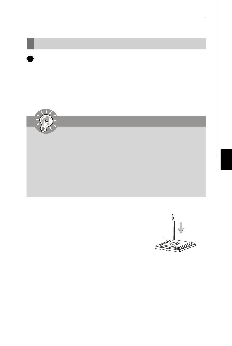
3. Обратите внимание на золотую стрелку (Gold arrow)
на CPU. Она должна быть направлена так, как показано
на рисунке. CPU можно вставить только при правильной
его ориентации.
4. При правильной установке CPU его контакты полностью войдут в разъем, и их
не будет видно. Помните, что любое применение силы при установке CPU
может вызывать серьезные повреждения системной платы.
5. Аккуратно прижмите CPU к разъему и опустите рычажок. Поскольку CPU при
опускании рычажка может переместиться, осторожно прижимайте CPU
пальцами в центре, так, чтобы он правильно и полностью зафиксировался в
разъеме.
Gold arrow
placement
Внимание
Перегрев
Перегрев может серьезно повредить центральный процессор и систему.
Чтобы уберечь процессор от перегрева, убедитесь в том, что
процессорный кулер работает нормально. Чтобы увеличить
теплорассеивание, убедитесь в том, что нанестите слой
теплопровадящей пасты (или теплопровадящей ленты) между
процессором и оребрениями.
Замена CPU
При замене CPU, во избежание его повреждения, обязательно отключите
источник питания или выньте вилку блока питания из розетки.
Ru-6
MS—7369 Mainboard
Установка процессора и вентилятора
Во избежание перегрева процессора при его работе обязательно установите
вентилятор процессора. Если у вас нет процессорного вентилятора,
пожалуйста, свяжитесь с дилером с целью приобретения и его установки до
того, как включите компьютер.
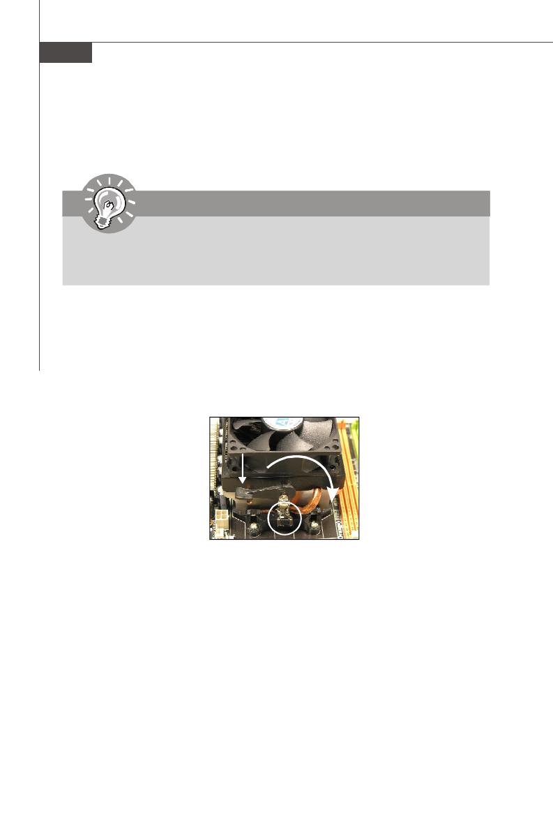
1. Разместите радиатор на узле крепления. Вначале зацепите один его край.
2. Затем нажмите на другой край, чтобы установить радиатор на узел крепления.
Найдите рычаг фиксации и поднимите его.
3. Зафиксируйте радиатор дальнейшим поворотом рычага.
4. Подключите кабель вентилятор CPU к соответствующему разъему системной
платы.
Fixed Lever
Внимание
Фото системной платы, показываемые в этой части,— только демострация
установки вентилятора. Выступление системной платы зависит от модели,
купленной вами.
Ru-7
Русский
Папять
DDR
Характеристики : 184—pin, 2.5v.
Одноканальный режим : Все модули памяти в разъемах ЗЕЛЕНОГО цвета.
Двухканальный режим : Модули памяти канала А в разъемах зеленого цвета.
Модули памяти канала В в разъемах пурного цвета.
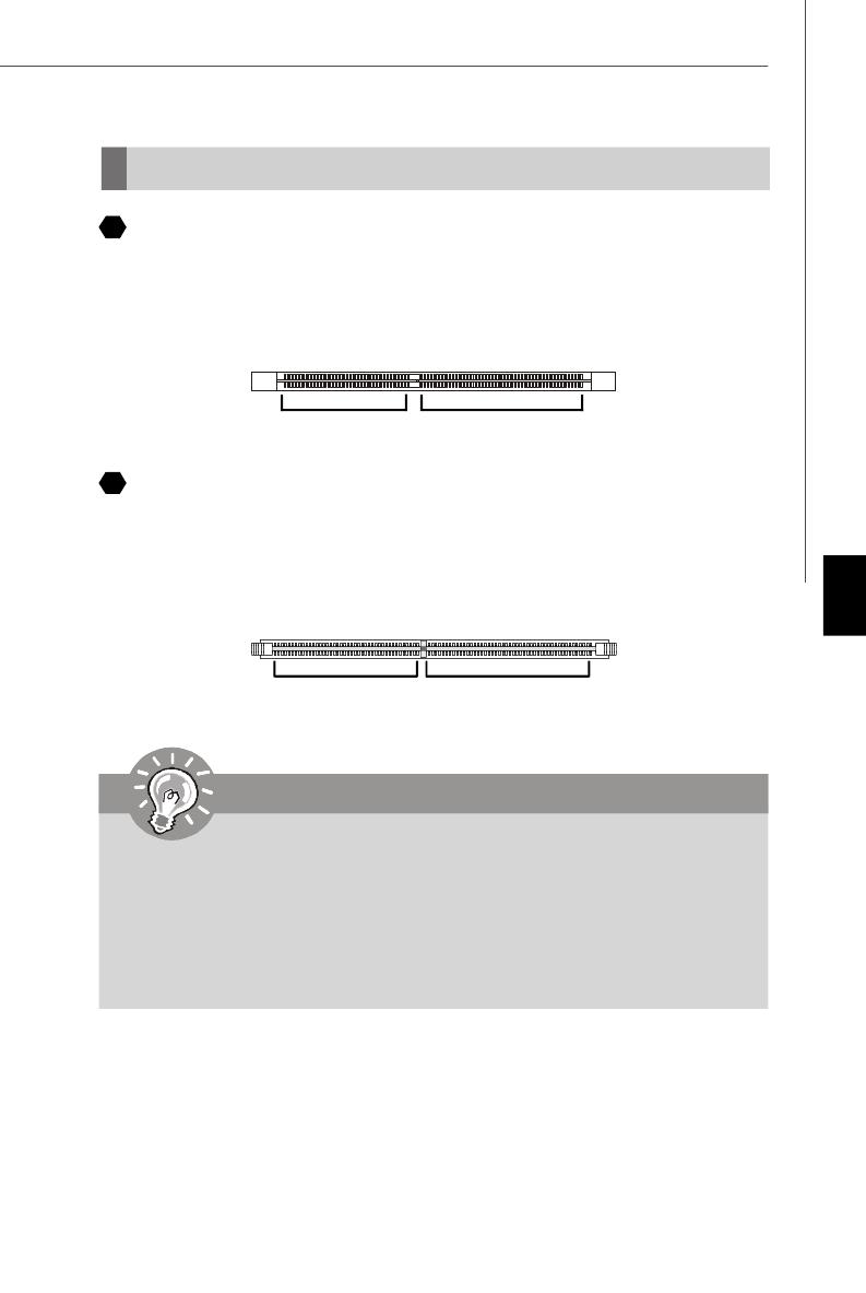
DDR2
Характеристики : 240—pin, 1.8v.
Одноканальный режим : Все модули памяти в разъемах ЗЕЛЕНОГО цвета.
Двухканальный режим : Модули памяти канала А в разъемах зеленого цвета.
Модули памяти канала В в разъемах оранжевого цвета.
40×2=80 pin 52x2=104 pin
2
3
Внимание
— МодулиDDR2 не взаимозаменяемы с модулями DDR и стандарт DDR2 не
имеет обратной совместимости. Следует устанавливать модуль памяти
DDR2 только в разъем DDR2 а модуль DDR — в разъем DDR .
— Для работы в двухканальном режиме убедитесь, ч то в разъемах разных
каналов у вас установлены модули одного типа и одинаковой емкости
— Чтобы система загружалась, вначале установите модули в разъемы
DIMM1.
64x2=128 pin56x2=112 pin
Ru-8
MS—7369 Mainboard
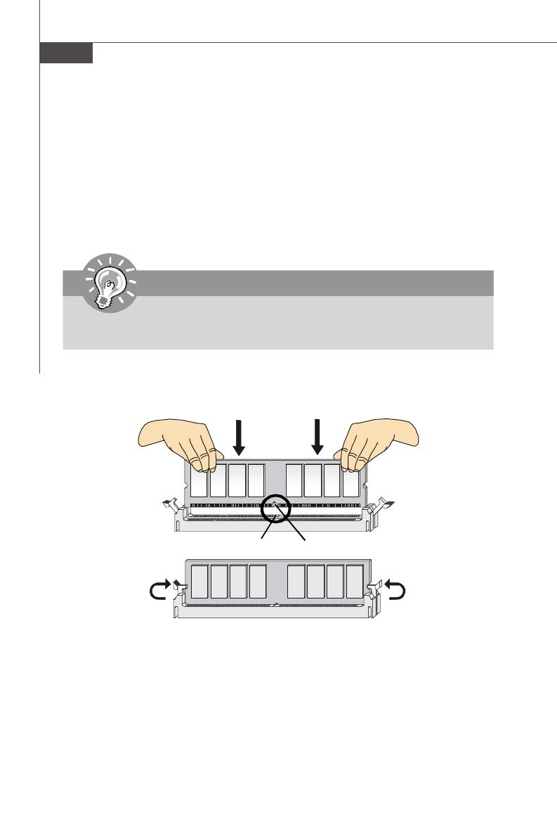
Установка подулей памяти
На модулях памяти DDR и DDR2 имеется прорезь, а в разъемах для них — выступ.
Для правильной установки модулей памяти выполните действия, перечисленные
ниже.
1. Модули памяти имеют только одну прорезь в середине. Модуль войдет в
разьем только при правильной ориентации.
2. Вставьте модуль в DIMM слот в вертикальном направлении. атем нажмите на
него, чтобы золоченые контакты глубоко погрузились в DIMM слот.
3. Пластиковые защелки на обоих концах разъема закроются автоматически.
Внимание
Вы можете едва видеть золотые контакты, если модули памяти правильно
войдут в DIMM слоте.
Volt
Notch
Ru-9
Русский
Соединители, перемычки, разъемы
Разъем FDD
Разъем поддерживает FDD емкостью 360Kб, 720Kб, 1.2Mб, 1.44Mб или 2.88Mб.
5
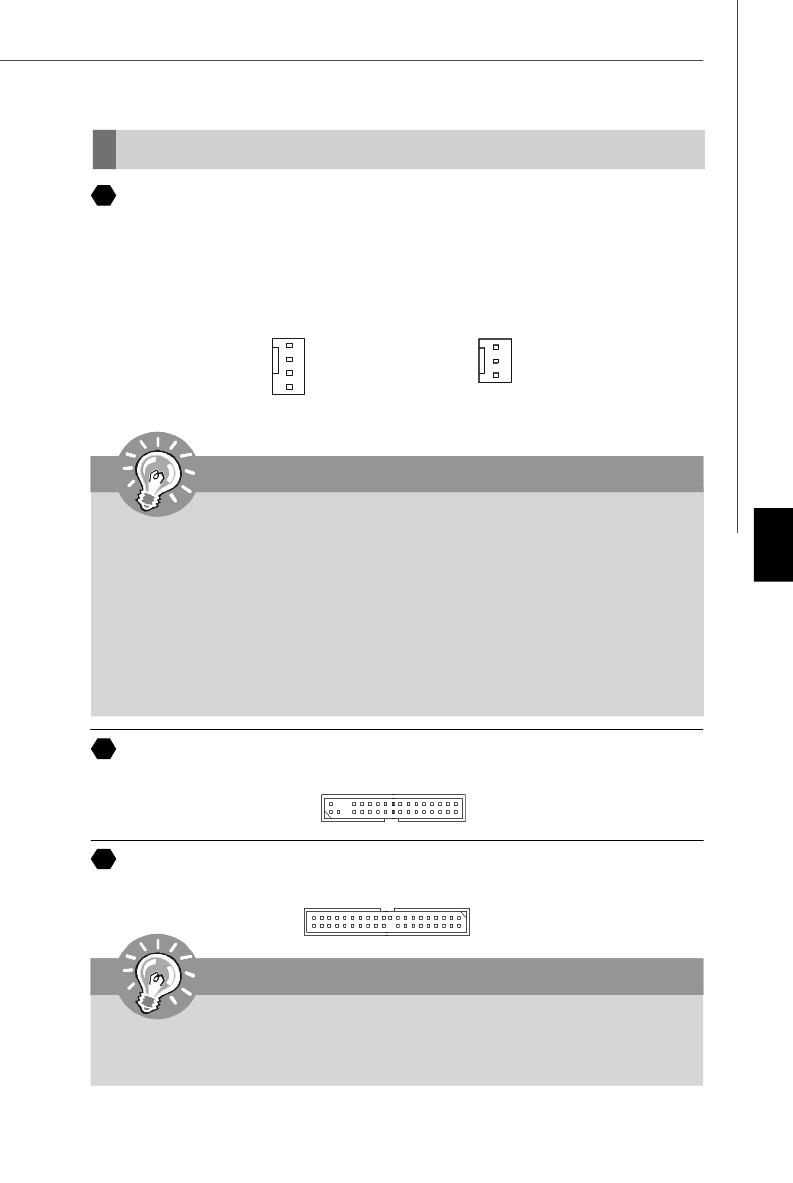
Разъемы питания вентиляторов
Разъемы питания вентиляторов поддерживают вентиляторы с питанием +12В.
Вентилятор процессора поддерживает функцию Smart FAN .При подключении
необходимо помнить, что красный провод подключается к шине+12В, черный — к
земле GND. Если на системной плате установлена микросхема аппаратного
мониторинга, необходимо использовать специальные вентиляторы с датчиками
скорости для реализации функции управления вентиляторами.
4
IDE разъем
Разъем поддерживает IDE жеткий диск, опций диск и другие IDE.
6
Внимание
При подключении двух устройств, следует установить второе в режим
Slave посредством перестановки перемычки. За инструкциями обратитесь
к документации изготовителя устройства.
SENSOR
+12V
GND
Control
CPU FAN
SYS FAN/ NB FAN/
POWER FAN
SENSOR
+12V
GND
Внимание
1. Чтобы узнать о моделях подходящих вентиляторов обратитесь,
пожалуйста, на официальный веб сайт AMD® или проконсультируйтесь
с продавцом.
2. Вентиляторы, установленные с питаниями с 3 пли 4 контактами, — оба
для CPUFAN.
3. CPUFAN поддерживает контроллер вентилятора. Вы можете
задать эту функцию в разделе BIOS Setup или использовать
утилиту Dual Core Center, которая автоматически контролирует
скорость вентилятора процессора, в зависимости от текущей
температуры процессора.
Ru—10
MS—7369 Mainboard
Соединители передней панели
Оба эти соединителя используются для подключения кнопок и индикаторов,
расположенных на передней панели корпуса . Соединитель JFP1 соответствует
руководству Intel® Front Panel I/O design.
Соединитель IEEE1394 (Зеленый)
Этот соединитель позволяет подключить порты IEEE 1394 на выносной планке
IEEE1394.
8
9
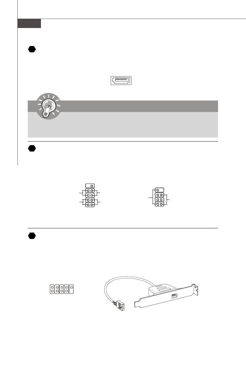
Разъем Serial ATA
Разъем — это высокоскоростной порт интерфейса Serial ATA. Любой разъем может
соединять с одним устройством Serial ATA.
7
Внимание
Избегайте, пожалуйста, резких изгибов кабеля Serial ATA . В противном
случае могут возникнуть потери данных при передаче.
Подключить
к соединителю IEEE1394
(Опция)
Speaker
1
2
910
HDD
LED
Reset
Switch
Power
LED
Power
Switch
JFP1
JFP2
78
Power
LED
1
2
1
2
9
10
TPA+
Ground
TPB+
Cable power
Key (no pin)
TPA-
Ground
TPB-
Cable power
Ground
Ru—11
Русский
Выносная планка SPDIF
(Опция)
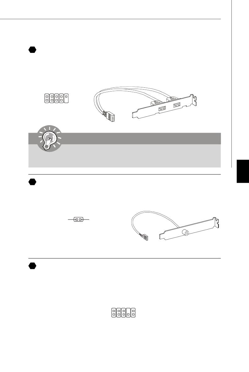
Выносные порты USB 2.0 (Желтый соединитель)
Разъем, совместим с руководством Intel® I/O Connectivity Design, идеально для
подключения таких высокоскоростных периферийных устройств, как USB HDD,
цифровые камеры, MP3 плееры, принтеры, и им подобные.
Выносная планка
USB 2.0 (Опция)
Внимание
Помните, что во избежание повреждений, контакты VCC и GND должны
быть правильно подключены.
10
Выносной разъем аудио (Azalia Spec)
Этот соединитель позволяет подключить выносной разъем аудио на передней
панели и совместим с руководством Intel
®
Front Panel I/O Connectivity Design.
11
12
USBOC
10
1
2
VCC
USB0-
USB0+
GND
Key (no pin)
VCC
USB1-
USB1+
GND
9
SPDIFO GND
1
2
9
10
MIC _L
MIC _R
LINE out_R
Front_JD
LINE out_L
Ground
Presence#
MIC_JD
NC(No pin)
LINE out_JD
Разъём S/PDIF—Out ( дополнительно, только для видеокарт с интерфейсом
HDMI )
Этот разъем предназначен для подключения интерфейса S/PDIF и обеспечивает
передачу цифрового звука с помощью HDMI интерфейса видеокарт.
Ru—12
MS—7369 Mainboard
Вход аудио с CD
Этот соединитель предназначен для подключения внешнего ввода аудио.
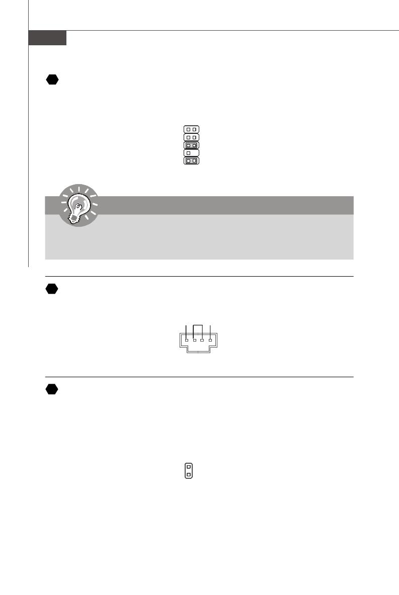
Датчик открывания корпуса
К этому соединителю подключется кабель выключатели, установленный в корпусе.
При открывании корпуса его механизм активитируют. Система запоминает это
событие и выдает предупреждение на экран. Предупреждение можно отключить в
настройках BIOS.
GND R
L
Выносной разъем аудио (AC97 Spec)
Этот соединитель позволяет подключить выносной разъем аудио на передней
панели и совместим с руководством Intel® Front Panel I/O Connectivity Design.
15
1
2
910
AUD_MIC
AUD_MIC_BIAS
AUD_FPout_R
HP_ON
AUD_FPout_L
AUD_GND
AUD_VCC
AUD_RET_R
Key
AUD_RET_L
13
Внимание
Если вы не используете выносной аудио разъем, то контакты 5 & 6, 9 & 10
следует соединить, чтобы сигнал проходил на разъемы задней панели. В
противном случае не будет работать линейный выход на задней панели.
14
1
2
CINTRU
GND
Ru—13
Русский
Соединитель для модуля IrDA
Этот соединитель позволяет подключить инфракрасный модуль IrDA. Для
использования функции IrDA следует включить ее в настройках BIOS. Эта функция
соответствует руководству Intel
®
Front Panel I/O Connectivity Design.
Соединитель последовательного порта
Разъем — это высокоскоростной последовательный порт связи 16550A с 16— битной
передачей FIFO. К этому разъему можно непрсредственно подключить серию
устройств.
Соединитель TV-выхода
Соединитель TV-выхода предназначен для подключения выносной планки выходных
TV-разъемов. На ней установлены разъемы нескольких типов. Выберите подходящий
для подключения вашего телевизора.
6
5
2
1
NC
VCC5
IRTX
NC
Ground
IRRX
16
17
18
3
1 4
Ground
Yout
Cout
COMP or CVBS
Ground (5)
1
9
2
DCD
SIN
SOUT
DTR
Ground
DSR
RTS
CTS
RI
Ru—14
MS—7369 Mainboard
1
9
2
10
DBG1
DBG2
DBG3
DBG4
Key
DBR1
DBR2
DBR3
DBR4
NC
Вывод сведений BIOS
На экране демонстрируются
логотип, название процессора и т.
д.
Проверка основной и расширенной
памяти от 240K to 640K и выше
1MB с помощью различных
алгоритмов.
Распределение ресурсов для
устройств ISA.
Инициализация контроллера HDD
Инициализация контроллеров IDE
привода и интерфейса.
Иинициализация контроллера
FDD. Инициализация привода
FDD и контроллера интерфейса.
Попытка загрузки
Установка нижней границы стека
и загрузка через прерывание INT
19h.
Загрузка операционной
системы
Включение питания системы
Сигнал не изменяется, если
процессор поврежден или
неправильно установлен.
Инициализация контроллера
клавиатуры.
Проверка VGA BIOS
Начало вывода на экран
логотипа видеокарты.
Инициализация процессора.
Вывод на экран сведений о
процессоре (названия, частоты
системной шины и т.д.).
Проверка RTC (Часов реального
времени)
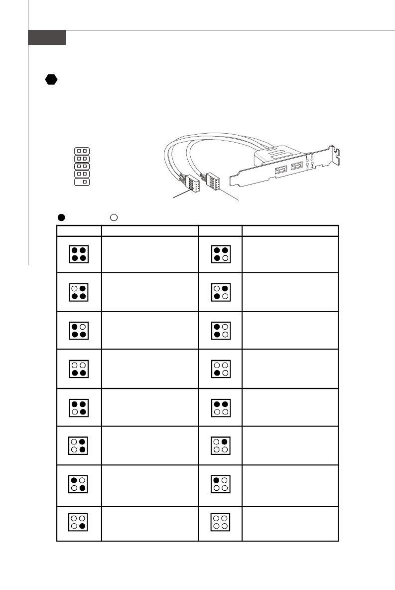
Описание
Красный
Зеленый
Сигнал LED
1 2
3 4
1 2
3 4
1 2
3 4
1 2
3 4
1 2
3 4
1 2
3 4
1 2
3 4
1 2
3 4
Описание
Сигнал LED
1 2
3 4
1 2
3 4
1 2
3 4
1 2
3 4
1 2
3 4
1 2
3 4
1 2
3 4
1 2
3 4
Начальная инициализация
чипсета
Тест памяти. Определяется
размер установленной памяти.
Сигнал не изменяется, если
память неисправна или
установлена неправильно.
Распаковка образа BIOS в память
для быстрой загрузки.
Инициализация интерфейса
видео.Определение частоты CPU,
поиск встроенного видеоадаптера.
Определение и запуск видеокарты.
Модуль
D—Bracket™ 2
(Опция)
К соединителю
модуля JDB1
К соединителю разъема USB
Соединитель подуля D-Bracket™ 2
Этот соединитель предназначен для подключения модуля D—Bracket™ 2. D—Bracket™
, который интегрирует четыре светодиода (LED) и USB порты.Это позволяет
позволяющих идентифицировать неисправности системы по 16 комбинациям
сигналов.
19
Ru—15
Русский
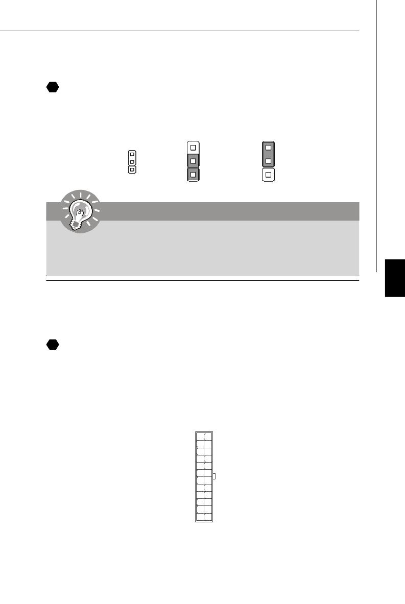
Перемычка очистки CMOS
Для сохранения данных о конфигурации системы встроенная память CMOS
питается от специальной батарейки. Благодаря памяти CMOS, каждый раз при
включении компьютера загружается операционная система. Если требуется
очистить память конфигурации системы, установите перемычку очистки CMOS в
положение “очистка”.
Подключение источника питания
Перед подключением разъема питания, во избежание повреждений обязательно
убедитесь, что все компоненты установлены правильно. Все разъемы питания
должны быть подключены к блоку питания ATX для обеспечения стабильной
работы системной платы.
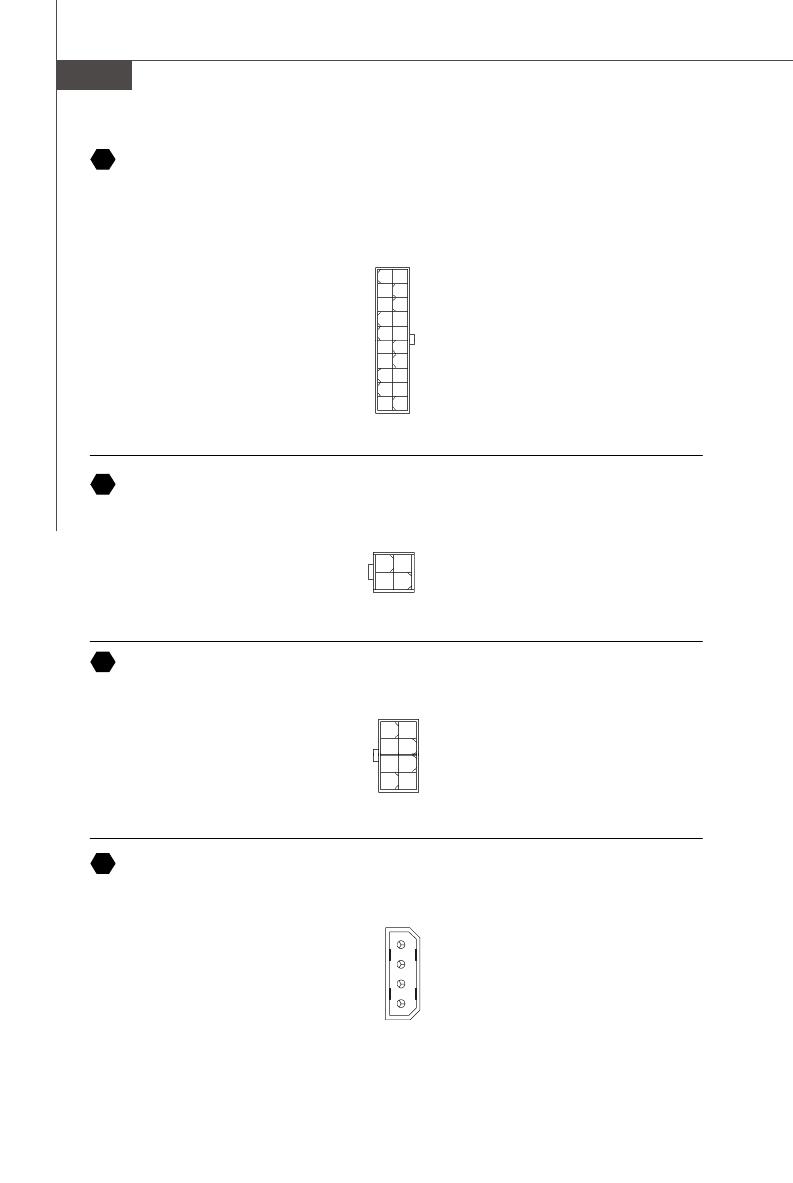
24-контактный разъем питания ATX
Этот разъем позволяет подключить 24-контактный источник питания ATX. Для
подключения источника убедитесь, что его разъем правильно ориентирован, затем
острожно вставьте его в ответную часть. Вы также можете использовать 20
контактный АТХ блок питания.
20
Очистка
Хранение ( обычно)
Внимание
Очистка CMOS производится соединением контактов 2—3 pin при
отключенной системе. Затем следует вернуться к соединению 1—2.
Избегайте очистки CMOS при работающей системе; это повредит
системную плату.
21
1
1224
13
+3.3V
+3.3V
GND
+5V
GND
+5V
GND
PWR OK
5VSB
+12V
+12V
+3.3V
GND
+5V
+5V
+5V
NC
GND
GND
GND
PS—ON#
GND
—12V
+3.3V
1
3
1
3
1
Ru—16
MS—7369 Mainboard
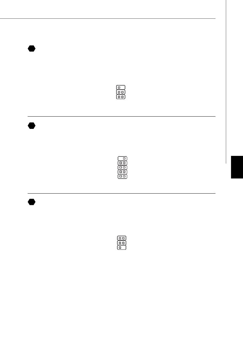
Разъем питания ATX 12V (2x2)
Этот разъем 12V предназначен для питания CPU.
Разъем питания ATX 12V (2x4)
Этот разъем 12V предназначен для питания CPU.
Разъем питания ATX 12V (1x4)
Этот разъем 12V предназначен для питания графической карты.
8
4
15
GND
GND
GND
GND
+12V
+12V
+12V
+12V
4
2
1
3
5V
GND
GND
12V
20-контактный разъем питания ATX
Этот разъем позволяет подключить 20— контактный источник питания ATX. Для
подключения источника убедитесь, что его разъем правильно ориентирован, затем
острожно вставьте его в ответную часть.
1
1020
11
3.3V
3.3V
GND
5V
GND
5V
GND
PWR OK
5VSB
12V 5V
5V
—5V
GND
GND
GND
PS—ON
GND
—12V
3.3V
22
23
24
25
1
3
4
2
GND12V
12V GND
Ru—17
Русский
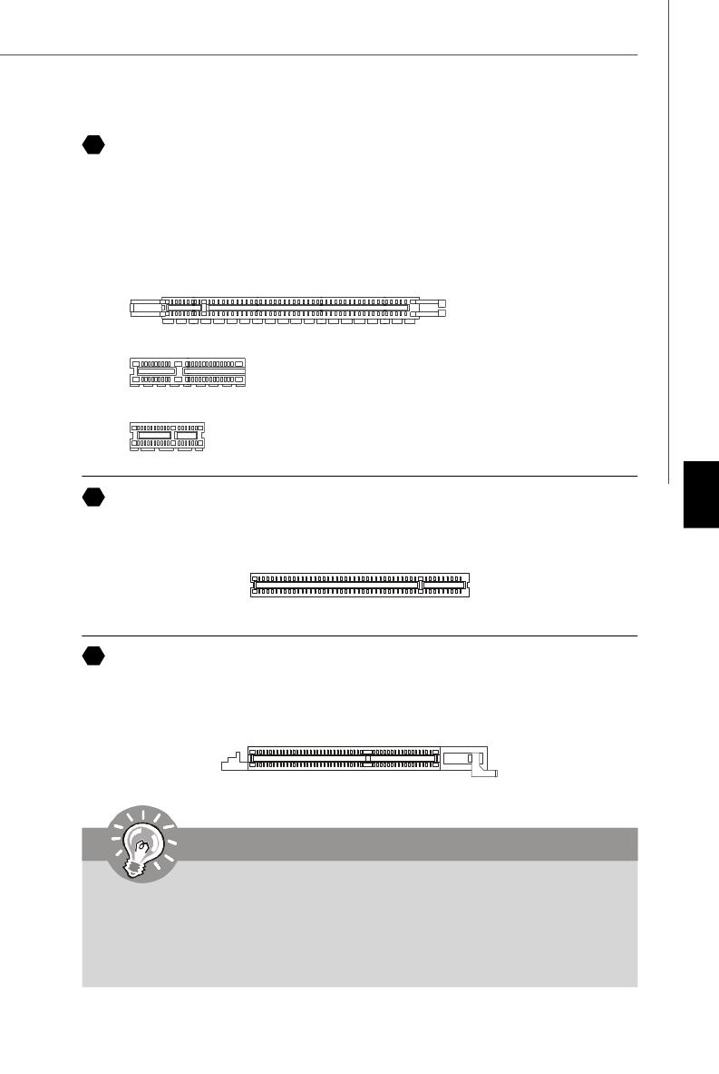
Разъемы PCI Express (x16/ x4/ x1)
PCI Express слот поддерживает дополнительные карты расширения интерфейса
PCI Express.
PCI Express x 16 слот поддерживает скорость передачи до 4.0Гб/с.
PCI Express x 8 слот поддерживает скорость передачи до 2.0Гб/с.
PCI Express x 4 слот поддерживает скорость передачи до 1.0Гб/с.
PCI Express x 1 слот поддерживает скорость передачи до 250 Мб/с.
Разъем PCI Express x 16
Разъем PCI Express x 4
Разъем PCI Express x 1
Разъем PCI
Разъемы PCI позволяет устанавливать карту LAN, карту SCSI, картуUSB и другие
дополнительные карты расширения, которые соответствуют характеристикам
PCI.
Разъем AGP
Разъем AGP позволяет установить графическую карту AGP. AGP — это интерфейс,
разработанный специально для графических карт 3D. Он обеспечивает прямой
доступ графического контроллера к системной памяти по 32-битному каналу с
тактовой частотой 66MHz.
26
27
28
Внимание
Перед установкой или извлечением карт расширения убедитесь, что
кабель питания отключен от электрической сети. Прочтите
документацию на карту расширения и выполните необходимые
аппаратные или программные установки для данной платы (перемычки,
переключатели или конфигурация BIOS).
Ru—18
MS—7369 Mainboard
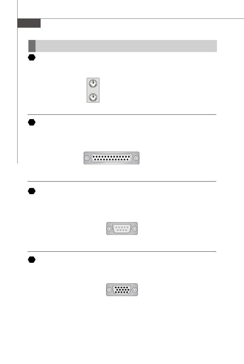
Задняя панель
Разъемы мыши / кливиатуры
Стандартные разъемы mini DIN PS/2
®
для подключения мыши/клавиатуры с
интерфейсом PS/2
®
.
Разъем параллельного порта
Параллельный порт — это стандартный порт для принтера. Он поддерживает режимы
EPP (усовершенствованный параллельный порт) и ECP (параллельный порт с
дополнительными возможностями).
Разъем последовательного порта
Это выскоскоростной последовательный порт связи 16550A с 16— битной
передачей FIFO. К этому разъему можно непрсредственно подключить мышь для
последовательного порта или другое устройство.
Разъем VGA
15-контактная розетка DB для подключения монтитора.
Разъем PS/2 для мыши (6-контактная
зеленая розетка
Разъем PS/2 для клавиатуры (6-
контактная пурпурная розетка )
(9-контактная вилка)
1 5
6 9
(15-контактная розетка DIN)
15
1115
A
B
C
D
13 1
1425
(25-контактная розетка Сentronic)
Ru—19
Русский
Порт IEEE1394
Порт 1394 на задней панели позволияет подключать устройства с интерфейсом
IEEE1394.
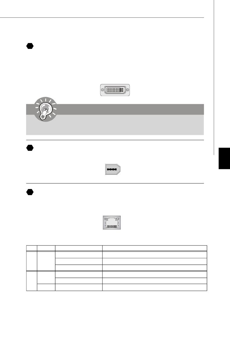
Разъем цифрового плоскопанельного монитора
Разъем DVI (Цифрового интерфейса видео) позволяет подключить LCD монитор.
Он обеспечивает высокоскоростное цифровое соединение комптютера и дисплея.
Для подключения LCD достаточно подключить кабель к разъему DVI и убедиться,
что второй его конец соответствующим образом подключен к монитору. За
дополнительной информацией обратитесь к документации монитора.
8
Внимание
Помните, что данный разъем DVI не поддерживает переходник DVI —
VGA.
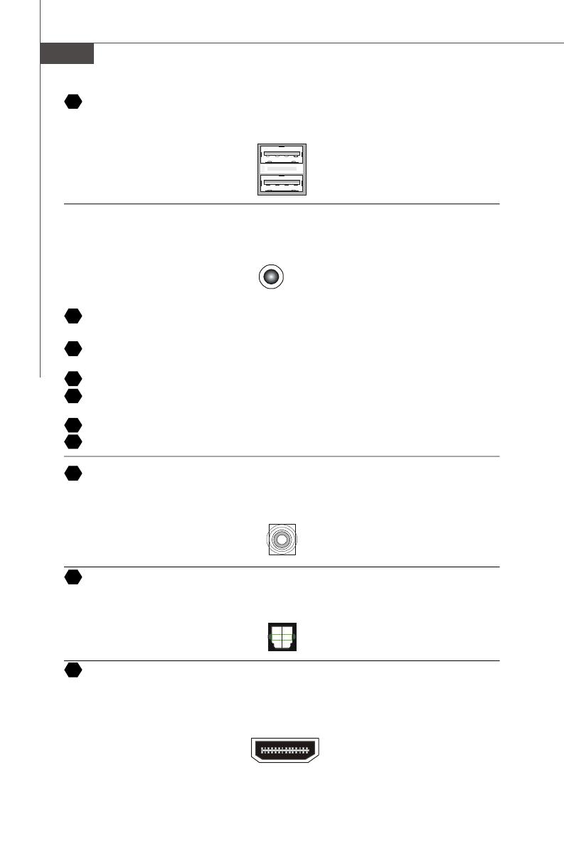
Разъем LAN
Стандартный разъем RJ—45 для подключения к локальной вычислительной сети
(LAN). К нему подключается кабель локальной сети.
E
F
G
LED Color LED State Condition
Нет LAN соединение не установлено.
Лев. Оранж. Есть (постоянно) LAN соединение установлено.
Есть ( пульсирует) Связъ с другим компютером по LAN.
Зелен. Нет Скорость передачи 10 Мб/с.
Прав. Есть Скорость передачи 100 Мб/с.
Orange Есть Скорость передачи 1000 Мб/с.
Ru—20
MS—7369 Mainboard
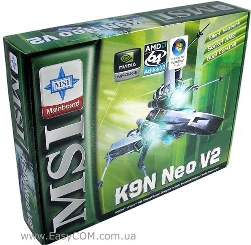
Порт USB
USB потр (Universal Serial Bus) позволяет подключать такие USB устройства, как
клавиатуру, мышь и т.д.
Аудио разъемы
Эти разъемы используются для подключения звуковых устройств. Разъемы,
выполняющие разные функции имеют различные цвета.
Выход аудио (Зеленый) — Линейный выход для подключения наушников или
акустических систем (АС).
Вход аудио (Голубой) — Линейный вход, используется для подключения внешего
CD проигрывателя, магнитофоноа или других звуковых устройств.
Микрофон (Розовый) — Разъем для подключения микрофона.
Выход CS (Оранжевый) — Выход на центральную АС и сабвуфер в режиме 5.1/
7.1.
Выход RS (Черный) — Выход на задние АС в режиме 4/ 5.1/ 7.1
Выход SS (Серый) — Выход на боковые AC в режиме 7.1
Коаксиальный разъем выхода S/PDIF
Этот разъем используется для подключения SPDIF (Формат цифровой передачи
от Sony & Philips) — для цифровой передачи звукового сигнала в наушники через
коаксиальный кабель.
Оптический разъем выхода S/PDIF
Этот разъем используется для подключения SPDIF (Формат цифровой передачи
от Sony & Philips) — для цифровой передачи звукового сигнала в наушники через
коаксиальный кабель.
H
I
J
N
M
O
P
K
L
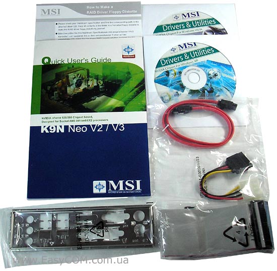
HDMI порт
HDMI (High—Definition Multimedia Interface) — это полностью цифровой интерфейс
для передачи несжатых потоков аудио и видео. HDMI поддерживает все
форматы видео, включая стандартное, улучшенное, или высокочетное видео,
плюс многоканальное цифровое аудио через единственный кабель.
Q
Note for Owners:
Guidesimo.com webproject is not a service center of MSI trademark and does not carries out works for diagnosis and repair of faulty MSI K9N Neo V2 Series equipment. For quality services, please contact an official service center of MSI company. On our website you can read and download documentation for your MSI K9N Neo V2 Series device for free and familiarize yourself with the technical specifications of device.
-
Gigabyte B560M AORUS PRO AX
To reduce the impacts on global warming, the packaging materials of this product are recyclable and reusable. GIGABYTE works with you to protect the environment.For more product details, please visit GIGABYTE’s website.B560M AORUS PROB560M AORUS PRO AXB560M AORUS PRO AXB560M AORUS PROUser’s ManualRev. 100112ME-B56MPRW-1001R …
B560M AORUS PRO AX Motherboard, 52
-
Renesas PG-FP6 V1.06
CoverPG-FP6 V1.06 Flash Memory Programmer User’s Manual Rev.8.00 Oct 2021 All information contained in these materials, including products and product specifications, represents information on the product at the time of publication and is subject to change by Renesas Electronics Corporation without notice. Please review the latest information published by Renesas Electronics Corporation throug …
PG-FP6 V1.06 Motherboard, 188
-
Gigabyte B460 HD3
To reduce the impacts on global warming, the packaging materials of this product are recyclable and reusable. GIGABYTE works with you to protect the environment.For more product details, please visit GIGABYTE’s website.B460 HD3User’s ManualRev. 1001 …
B460 HD3 Motherboard, 44
-
AXIOMTEK ATX6022/6
ATX6022/6 User’s Manual 1 ISA / 4 PCI / 2 PICMG Backplane ©Copyright 2010 AXIOMTEK Co., Ltd. Version A3 May 2010 Printed in Taiwan 94160221520E 4 III. Board Dimensions ATX6022/6 User’s Manual 1 ISA / 4 PCI / 2 PICMG Backplane ©Copyright 2010 AXIOMTEK Co., Ltd 1 Version A3 May 2010 Printed in Taiwan 94160221520E I. Jumper Settings &am …
ATX6022/6 Motherboard, 2
-
Linear Technology DC1819A
1dc1819afaDEMO MANUAL DC1819APARAMETER CONDITIONS VALUEMinimum Input Voltage VINx 1.7VMaximum Input Voltage VINx 5.5VMaximum Output Current CLIMx Resistor-Adjustable 4ACLIMx Internal Limit 6ACLIMx Clamp Voltage Current Limit 0.5VForward Voltage Drop VINx = 3.6V, IOUTx = 1A 50mV TypReverse Turn-Off Voltage VINx – VOUTx –30mVEnable Threshold EN1 and EN2 800mV DESCRIPTIONLTC4415EMSEDual 4A Ideal …
DC1819A Motherboard, 7
-
EPOX F62
8!Motherboard,67Motherboard..0� …
F62 Motherboard, 10
-
IWILL P55TV
i EC Declaration of Conformity We Iwill Corp. No. 9-1, Kong 6th RD., Lin Kou 2nd Industrial Park, Taipei, Taiwan R.O.C. declare under sole responsibility that the P55TV motherboard meets the intent of Directive 89/336/ECC for Electromagnetic Compatibility. Compliance was demonstrated to the following specifications as listed in the official Journal of the European Communities: …
P55TV Motherboard, 72
-
Advantech SIMB-A01
SIMB-A01 Startup Manual 1Before you begin installing your card, please make sure that the following items have been shipped:• 1 x Intel Q35 ATX Main board• 1 x CD ROM per carton, which contains the followings: — User’s Manual in PDF file — Drivers• 1 x SATA cable kit (SATA/Power)• 1 x I/O Shield• 1 x Startup Manual per cartonIf any of these items are missing or d …
SIMB-A01 Motherboard, 4
Popular Motherboard User Guides:
Несмотря на выход новых материнских плат на чипсетах AMD 7 серии с поддержкой Hyper Transport 3.0 пройдет еще какое-то время прежде чем предложения на них станут в полной мере актуальными для пользователей всех категорий. А пока AMD «исправляет ошибки», сделанные при производстве процессоров AMD Phenom, и готовит к выпуску новые недорогие процессоры, старые модели материнских плат остаются востребованными. Делая выбор между компьютерными системами Intel и AMD, в сторону последних пользователи смотрят с точки зрения более низкой стоимости при тех же функциональных возможностях. И когда приходится выбирать между «старыми» и новыми платформами, которые безусловно имеют преимущества, то иной раз не хочется мириться с более высокой стоимостью, которая обусловлена новизной. Ведь по сути преимуществ у новых платформ на самом деле не так уж много — это поддержка HyperTransport 3.0 и PCI Express 2.0. При этом новый стандарт шины PCI Express 2.0 хотя и обеспечивает удвоенную пропускную способность, но на практике для одной видеокарты он не приносит ощутимой пользы и этот факт мы подтвердили, тестируя видеокарту ASUS GeForce 8800 GT 512Mb. Хотя, с точки зрения разгона платформы на чипсетах AMD 7-й серии конечно выглядят привлекательней, но оверлокингом занимаются далеко не все. Так что продолжаем знакомиться с массовыми платформами, и в этот раз протестируем материнскую плату MSI K9N Neo V2 на чипсете NVIDIA nForce 520.

Спецификация материнской платы MSI K9N Neo V2:
NVIDIA nForce 520
Athlon 64 X2/Athlon 64 FX/Athlon 64/Sempron
Системная шина, МГц
DDR2 800/667/533 МГц
4 x 240-контактных DIMM двухканальной архитектуры до 8 Гб
1 x PCIe x16
2 x PCIe x1
3 x PCI 2.2
4 x Serial ATA 3.0Гб/с с RAID 0, 1, 10, 5 или JBOD
1 x Ultra DMA 133/100/66/33
Кодек 8-канальнго звука Realtek ALC888
High Definition Audio
Сетевой контроллер Realtek RTL8111B (10/100/1000 Мб)
24-контактный разъем питания ATX
4-контактный ATX12V разъем питания
Алюминиевый радиатор на чипсете
Разъемы для вентиляторов
1 x CPU
2 x корпусных вентилятора
Внешние порты I/O
2 x PS/2 порта для подключения клавиатуры и мыши
1 x LPT
1 x COM
4 x USB 2.0
1 x LAN (RJ45)
8 канальный аудио выход
Внутренние порты I/O
6 x USB
1 x S/PDIF выход
4 х SATA
1 x IDE
1 x FDD
1 x CD In
Front panel audio connector
Изменение частоты: FSB, HT, PCI-Express, память.
Изменение напряжения: процессор, память
1 x SATA кабель
1 x SATA переходник питания SATA
1 x UltraDMA 100/66 кабель
Инструкция и руководство
2 х CD с утилитами и драйверами для Windows Vista и Windows XP
Форм-фактор Размеры, мм
Новую версию BIOS для MSI K9N NEO V2 можно скачать здесь.
Драйвера для MSI K9N NEO V2 находятся здесь.
Материнская плата MSI K9N NEO V2 упакована в картонную коробку зеленого цвета, на которой изображен космический корабль.
В комплект входит:
- шлейф Serial ATA;
- шлейф UltraDMA 133/100/66;
- переходник питания SATA;
- инструкция и руководство
- 2 х CD с утилитами и драйверами для Windows Vista и Windows XP;
- заглушка.
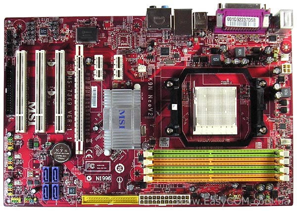
Материнская плата MSI K9N NEO V2 распаяна на том же PCB, что и MSI K9N NEO V3. Компоновка у этих материнских плат достаточно хорошая – разъемы питания расположены по краям, а защелки слотов оперативной памяти перекрываться видеокартой не будут. Хотя все же есть и некоторые замечания. Так, в верхний слот PCIe x1 можно будет вставить только очень короткую плату, так как недалеко от него находиться достаточно габаритный алюминиевый радиатор. Еще одним недостатком является размещенный в левом нижнем углу разъем FDD — подключенный к нему шлейф не получится аккуратно уложить в корпусе. Материнская плата MSI K9N NEO V2 лишена полимерных конденсаторов, которыми оснащается чуть более дорогая материнская плата MSI K9N NEO V3.
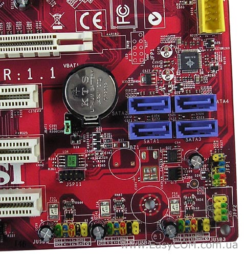
Чипсет NVIDIA nForce 520 поддерживает четыре порта SATA с возможностью создания RAID массивов 0, 1, 0+1, 5, JBOD и один разъем IDE, который позволяет подключить два устройства UltraDMA 133/100/66/33. В правом нижнем углу размещены шесть портов USB, которые имеют цветную маркировку. Разъемы фронт-панели, расположенные в нижней части с правого края, также имеют цветовую маркировку, упрощающую процесс подключения. Джампер сброса BIOS удобно расположен возле батарейки.
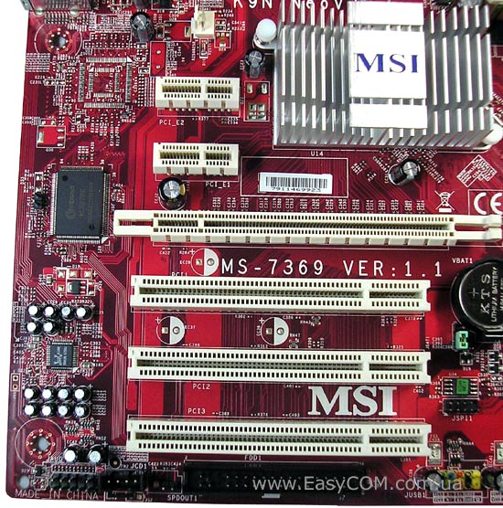
На материнской плате MSI K9N NEO V2 есть три слота PCI, два PCIE х1 и один слот для видеокарты PCIE х16. С левого края материнской платы распаян HDA кодек 8-канального звука Realtek ALC888, а возле панели разъемов ввода/вывода находится гигабитный сетевой контроллер Realtek RTL8111B. Аудиоразъем фронт-панели находится в левом нижнем углу платы и поддерживает стандарты HDA и AC’97.
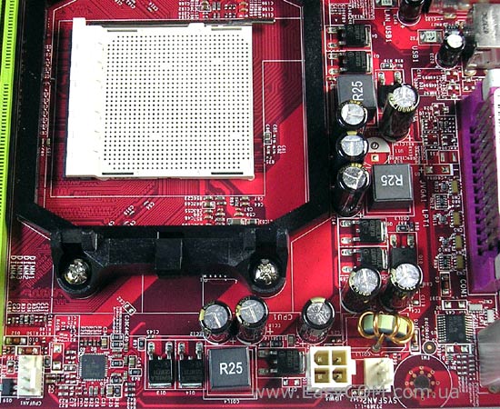
Стабилизатор питания процессора трехканальный, собран на конденсаторах с жидким электролитом и на N-канальных полевых транзисторах Infineon IPD09N03lA (25 В, 8,6 мОм, 50 A). Рамка крепления процессорного кулера имеет только 2 зубца, что не очень надежно.

На задней панели выведены следующие порты: два PS/2 для клавиатуры и мыши, четыре разъема USB, LPT и COM порт, разъем RJ45 для сетевых соединений и шесть audio-разъемов для 8-канального звука.
На материнской плате MSI K9N NEO V2 есть три разъема для подключения вентиляторов: 4-контактный для процессорного кулера расположен чуть выше разъема AM2, возле слотов оперативной памяти; а еще два 3-контактных для корпусных вентиляторов размещены с левой стороны материнской платы.
В материнской плате MSI K9N NEO V2 используется AMI BIOS. Для проведения тестирования мы обновили прошивку до Ver. 2.4 (23.11.07).
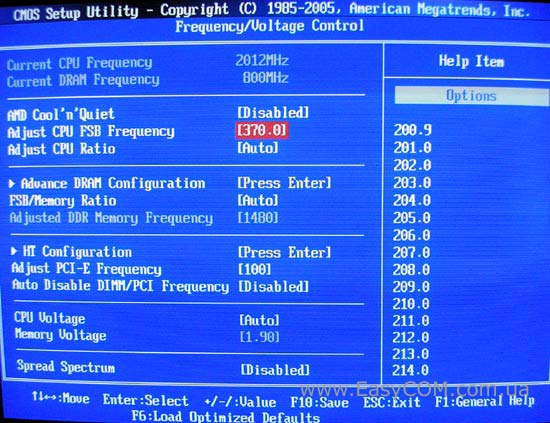
Практически все настройки, необходимые для разгона, собраны в разделе «Frequency/Voltage Control».
Для просмотра содержания инструкции Вам понадобится программа Adobe Reader или DjVu.
Если на Вашем компьютере они не установлены, то Adobe Reader можно скачать с сайта Adobe  , а DjVu с сайта DjVu
Смотрите также другие инструкции раздела Материнские платы:
Смотрите также другие инструкции раздела MSI:
Инструкция MSI K9A2 Neo2 на русском языке в формате pdf для устройства: материнская плата AMD. Прочитайте инструкцию для ознакомления с функциями и условиями эксплуатации, характеристиками и способами исправления неисправностей. Данное руководство пользователя поможет использовать весь функционал изделия и увеличит срок службы при условии соблюдения всех правил изложенных в документе.