-
Contents
-
Table of Contents
-
Bookmarks
Quick Links
GE
Sensing & Inspection Technologies
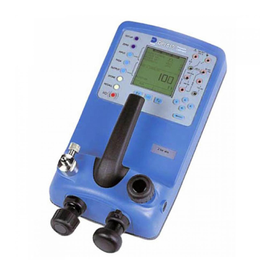
Druck DPI 610/615 IS
Intrinsically Safe Portable Pressure Calibrator
User manual — K0430
Visit us at www.TestEquipmentDepot.com
99 Washington Street
Melrose, MA 02176
Phone 781-665-1400
Toll Free 1-800-517-8431
Related Manuals for GE Druck DPI 610
Summary of Contents for GE Druck DPI 610
-
Page 1
99 Washington Street Melrose, MA 02176 Phone 781-665-1400 Toll Free 1-800-517-8431 Visit us at www.TestEquipmentDepot.com Sensing & Inspection Technologies Druck DPI 610/615 IS Intrinsically Safe Portable Pressure Calibrator User manual — K0430… -
Page 2
WARNING Before operating this intrinsically safe instrument, read the safety instructions and the special conditions stated on the ATEX certificate (Appendix 2) Safety The manufacturer has designed this equipment to be safe when operated using the procedures detailed in this manual. Do not use this equipment for any other purpose than that stated. -
Page 3
K0430 Issue No. 2… -
Page 4
ATEX Approved Models Introduction These instructions detail the requirements for using the DPI 610 IS and DPI 615 IS intrinsically safe pressure calibrator in a hazardous area. Read the whole publication before starting. Markings II 1 G…………..Equipment group & category Ex ia IIC T4 Ga………….. -
Page 5
Electrical Parameters Maximum Output Parameters at the External Measurement Connectors: lin (SK1) Vin (SK2) SwitchIn (SK3) = 1.1V d.c. = 1.1V d.c. = 1.1V d.c. = 0.16 mA d.c. = 0.11 µA d.c. = 12 mA d.c. = 0.15 mW = 0.03 µW = 11 mW = 0.05 µF… -
Page 6
Specification Safe working pressure 20 bar range (300 psi) 1.75 x full-scale 350 bar range (5000 psi) 1.2 x full-scale 400 bar range (6000 psi) 1.5 x full-scale All other ranges 2 x full-scale Accuracy Combined non-linearity, hysteresis and repeatability ±70 mbar range (2 inHg) 0.05% F.S. -
Page 7: Table Of Contents
Introduction General Description of Procedures Summary of Functions Using this Guide OPERATOR CONTROLS DISPLAY HARD KEY FUNCTIONS SOFT KEYS CURSOR KEYS ELECTRICAL CONNECTIONS Getting Started Fitting Batteries Switching On Change Pressure Units Voltage and Current Measurement Typical Calibration Set-up (Pressure to Voltage) Zero Display Reading Task Selection Task Key…
-
Page 8
Advanced Task General Select Input Ambient Temperature Measurement Process Functions Tare Process Function Min/Max Process Function Filter Process Function Flow Function % Span Select Output Electrical Outputs (Loop Power) mA Step mA Ramp mA Value Define New Task Clear Task Memory Operations Saving Display or Data Log Store Operations (Screen Snapshots) -
Page 9
Date and Time (Real Time Clock) Date Format Set Date Set Time Calibration General Calibration Check Calibration Adjustment Guide to Calibration Procedures Test Equipment Using the Calibration Menu Change PIN Calibrate Internal Ranges Internal Pressure Range Voltage Input Range (5 Volts) Voltage Input Range (30 Volts) Current Input Range (55 mA) Current Output Range (24 mA) -
Page 10: Description Of Procedures
INTRODUCTION Summary of Functions General The DPI 610 IS and DPI 615 IS intrinsically safe instruments measure and display pneumatic and hydraulic pressure applied to the test port. Pressure measurement can be absolute, gauge and sealed gauge and in ranges from 2.5 mbar to 700 bar (1.0 inH to 10000 psi).
-
Page 11: Summary Of Functions
INTRODUCTION Summary of Functions Using This Guide The following key symbols are used in the procedure diagrams: Shaded cursor keys indicate that a combination of these four keys, Up, Down, Left and Right should be used to (e.g.) enter an alpha numeric value or to select a function.
-
Page 12: Operator Controls
INTRODUCTION Summary of Functions OPERATOR CONTROLS (Figure 1 and 2) These divide into two groups, the operator/display controls (Figure 1) and the pressure/ vacuum generation components (Figure 2). The operator controls and a typical display, common to all instrument versions, is shown below. max 30V DPI 615 IS TASK: BASIC…
-
Page 13: Hard Key Functions
INTRODUCTION Summary of Functions HARD KEY FUNCTIONS (Fig. 1) Page Function reference This key selects the instrument ON and OFF. The SETUP key provides access to the instrument’s general SETUP* configuration parameters that are set-up to certain default parameters on delivery. The ZERO key zeroes either the selected input or output display, only if ZERO the display reading is within 5% of zero.
-
Page 14: Soft Keys
INTRODUCTION Summary of Functions SOFT KEYS (Fig. 1) Three soft keys, designated F1, EXIT and F2, are situated immediately below the display as shown below. These keys have their function allocated by the instrument software which is indicated in the bottom of the display (Voltage for F1 and Units for F2 in this example).
-
Page 15: Electrical Connections
INTRODUCTION Summary of Functions ELECTRICAL CONNECTIONS Cover, closed when not using connectors External transducer RS232 connector Temperature sensor Figure 3 — Electrical System Connections Measurement inputs and Source outputs are made via the control panel sockets as shown below: max 30V DPI 615 IS CAT II TASK: BASIC…
-
Page 16: Getting Started
Getting Started Fitting Batteries Manufacturer Type No. Energizer Industrial Type EN93 Energizer Type E93.LR14.C.AM2 Duracell Type MN1400-LR14 Varta No.4014 Type LR14.C.AM2 Procell Industrial Type MN1400-LR14 Cover fixing screws. TASK: BASIC Six alkaline C cells, see table. Only use the battery type in VOLTAGE the table.
-
Page 17: Change Pressure Units
Getting Started Change Pressure Units To change the pressure units proceed as follows. If the four units displayed are not the units required, press TASK and select any task, other than BASIC, press SETUP and proceed as detailed on page 36. To return to BASIC mode, press TASK and select BASIC. In BASIC mode, the unit is configured to carry out basic Pressure to Voltage (P to V) or Pressure to Current (P to I) tests, a typical test procedure follows: Voltage and Current Measurements…
-
Page 18: Typical Calibration Set-Up (Pressure To Voltage)
Getting Started Typical Calibration Set-up (Pressure to Voltage) Connect a device under test to the instrument as shown below: Max 30V CAT II DPI 615 IS TASK: BASIC VOLTAGE PRESSURE INT PRESSURE CURRENT UNITS EXIT A — External pressure source (indicator instruments only) B — Pressure regulator C — Pressure/voltage device D — Barrier E — Excitation 10V F — Safe area •…
-
Page 19: Task Selection
Task Selection Task Key The TASK key is used to set-up the instrument for a number of specific types of test. There are two modes BASIC and ADVANCED and nine other specific types of test which automatically configure the instrument on selection from the TASK menu. The tasks available under the TASK menu are held on three pages shown below.
-
Page 20: Cal Mode (Dpi 615 Instruments Only)
Task Selection Cal Mode (DPI 615 versions only) Cal mode, which is available in tasks P-I, P-P, P-V, P-P, P-DISPLAY and P-SWITCH, provides a method of setting up test parameters manually. Downloaded test procedures can also automatically set up and turn on the Cal Mode function. The method of turning on and setting up Cal Mode is shown below for a P-I task.
-
Page 21: Taking Measurements
Taking Measurements Pressure Transmitter (P-I) Task Select the P-I task from the task menu and connect the Unit Under Test (UUT) to the calibrator as shown below: Max 30V CAT II DPI 615 IS TASK : P-I SNAPSHOT MODE CURRENT PRESSURE INT EXIT A — External pressure source (indicator instruments only) B — Pressure regulator…
-
Page 22: Pressure Converter (P-P) Task
Taking Measurements Pressure Converter (Pressure to Pressure) Task Select the P-P task from the task menu and connect the Unit Under Test (UUT) to the calibrator as shown below. Testing a converter requires one pressure to be applied to the unit under test (UUT) and another (converter output) to be measured. The additional measurement is provided by the external transducer option.
-
Page 23: Current To Pressure Converter (I-P) Task
Taking Measurements Current to Pressure Converter (I-P) Task Max 30V CAT II DPI 615 IS TASK : I-P SNAPSHOT MODE PRESSURE INT OUTPUT NEW VALUE CURRENT EXIT A — External pressure source B — Pressure to current device (24V) C — Barrier D — Safe area E — External supply •…
-
Page 24: Pressure To Display (P-Display) Task
Taking Measurements Pressure to Display (P-DISPLAY) Task P-Display is a special application of Data Log. To use this mode, select Data Log from the Store Mode menu as detailed on page 36. Connect the UUT to the instrument as shown below and, if required, turn on and set-up Cal Mode (see page 11).
-
Page 25: Leak Test (Leak Test) Task
Taking Measurements Leak Test (LEAK TEST) Task max 30V DPI 615 IS TASK : LEAK TEST SNAPSHOT MODE PRESSURE INT WAIT secs DURATION secs START PRESS STOP PRESS PRESS CHANGE LEAK RATE bar/m CHANGE VALUE A — External pressure source B — Pressure regulator C — Device/system under test •…
-
Page 26: Transmitter Simulator (Tx Sim) Task
Taking Measurements Transmitter Simulator (TX SIM) Task When used with an external voltage source (see page 24), provides a current output proportional to the calibrator’s measured output pressure (indicated pressure on indicator only version). Select task TX SIM. Press EXIT to skip set-up screen if parameters are correct.
-
Page 27: Relief Valve Test (Rel Valve) Task
Taking Measurements Relief Valve Test (REL VALVE) Task To carry out a relief valve test, press TASK and select REL VALVE. Connect the output pressure port of the instrument to an external system as shown below: max 30V DPI 615 IS TASK : RELVALVE SNAPSHOT MODE MAXIMUM…
-
Page 28: Advanced Task
Advanced Task Select Input General Advanced task allows the user to configure the instrument to monitor one of a number of different input measurements and outputs (sources). Additionally, five process functions, Tare, Max/Min, Filter, Flow and % Span can be applied to the input functions. Select Input To select an input channel, select ADVANCED task from the task menu.
-
Page 29: Process Functions
Advanced Task Process Functions Process Functions If required, the following process functions are available on the input display but only in ADVANCED task. If the instrument is in any other mode i.e. BASIC or any other task mode, the input and output displays must first be configured in ADVANCED task. Note: PROCESS functions are not available to the output channel.
-
Page 30: Tare Process Function
Advanced Task Process Functions • Tare Process Function To set-up a Tare function, enable TARE from the process menu and press F1 to enter the Tare SETTINGS functions. Disable TARE by entering process menu and turning the function OFF. Note: Last TARE setting is retained and will be applied when function is next enabled.
-
Page 31: Min/Max Process Function
Advanced Task Process Functions Min/Max Process Function • To set-up an input display to show min/max and present input reading, enable MIN/MAX from the process menu and press F1 (SETTINGS) to provide RESET function. The display now shows the max/min values as follows: Reset Max/Min display at any time by pressing the F1 key.
-
Page 32: Flow Function
Advanced Task Process Functions Flow Function • To apply the flow function to a selected input, enable FLOW from the process menu and press ENTER. The square root symbol is displayed beside the input value to indicate that the FLOW function is active: To cancel FLOW, press INPUT and turn function OFF at the process menu.
-
Page 33: Select Output
Advanced Task Select Output Select Output To display an output channel, select ADVANCED mode from the task menu. The display shows the list of output selections and, if available, the UNITS soft box (F2). The following procedure shows the method of output channel selection from two pages of options.
-
Page 34: Ma Step
Advanced Task Select Output mA Step To select one of the electrical output programs, press the OUTPUT key and proceed as follows: On selection of (e.g.) Linear, the output display window changes to show the selected program of output currents: •…
-
Page 35: Ma Ramp
Advanced Task Select Output mA Ramp Press the OUTPUT key and select mA Ramp as shown previously in mA Step. • Define ramp required by entering START and END current values as shown below: • Connect an external power source as shown on page 24. •…
-
Page 36: Ma Value
Advanced Task Select Output mA Value Press the OUTPUT key and select mA Value from the output menu. The procedure is shown below: • Connect an external power source as shown on page 24. • Use up and down cursor keys to adjust output current level. While the loop is made, a status display indicates OK.
-
Page 37: Define New Task
Advanced Task Task Setup/Removal Define New Task To define a new task, proceed as follows. • Select ADVANCED from TASK menu. • Using the INPUT key, select the required input for the input display and set-up any process functions required. •…
-
Page 38: Memory Operations
Memory Operations Store Saving Display or Data Log In Store Mode three memory operations can be set-up: None, Snapshot and Datalog. Refer to Using SETUP for details. Store Operations (Screen Snapshots) To store any display (menu displays excepted), press the STORE key. This saves the current display to the next available location.
-
Page 39: Datalog Operations
Memory Operations Datalog Data Log Operations Data Log is a special application of store mode which enables the calibrator to either automatically log displays at preset time intervals or to manually log a display on operation of the STORE key. Logged data is written to a user specified file. To set-up a Data Log file, proceed as follows.
-
Page 40: Recall Data Log Files
Memory Operations Datalog Recall Data Log Files To recall a Data Log file to the display, ensure that DATA LOG is selected from the SETUP menu and proceed as follows: Data Log files can be displayed either as text (stored screens) or in graphical form. To display as text, proceed as follows from the File Summary menu.
-
Page 41: Uploading Data Log Files
Memory Operations Datalog Uploading Data Log Files WARNING THE RS232 INTERFACE MUST ONLY BE USED IN A SAFE AREA Connect the RS232 socket of the instrument into either the COM1 or COM2 port of the PC. Ensure that the RS232 parameters set in the PC match those of the instrument. The RS232 parameters of the instrument can be checked as detailed on page 38.
-
Page 42: Downloading Procedure Files (Dpi 615 Instruments Only)
Memory Operations Datalog Downloading Procedure Files (DPI 615 instruments only) WARNING THE RS232 INTERFACE MUST ONLY BE USED IN A SAFE AREA Complete test procedures may be downloaded from a PC to the DPI 615 instrument via the RS232 port. A procedure consists of a number of Druck Universal Command Interface (DUCI) commands that are usually assembled by a linking management software application (e.g.) Druck Intecal.
-
Page 43: Running Procedure Files (Dpi 615 Instruments Only)
Memory Operations Datalog Running Procedure Files (DPI 615 instruments only) To run a procedure, make sure that the instrument is set to Store mode, Data Log (see page 36), and proceed as follows: After selecting F1, proceed by entering the User ID and Serial Number and then select F1 (Continue) and follow the on-screen procedural instructions: When the test procedure for a given UUT has been completed, the result of running the first test is stored as an AS FOUND file.
-
Page 44: Recalling Data Files (Dpi 615 Instruments Only)
Memory Operations Datalog Recalling Data Files (DPI 615 instruments only) Data or results files generated by running procedures are stored in the instrument’s data log directory. To recall a data file to the display, make sure that DATA LOG is selected from the SETUP menu and proceed as follows: Use the cursor keys to select either the AS FOUND option or the AS LEFT option for display.
-
Page 45: Using Setup
Using Setup General SETUP mode is available in all modes except BASIC and permits the changing of the following instrument parameters. • Store Mode — None, Snapshot, Data Log. • Contrast. • Settings — Units, Language, RS232 parameters, Powerdown and Calibration Routines (Refer to page 41 for calibration details).
-
Page 46: Settings — Select Setup Option
Using Setup Settings — Select Setup Option To select one of the SETTINGS options from the set-up menu, proceed as follows: Units UNITS Select from the SETTINGS menu and proceed as follows: Define Special Units Select UNITS from the SETTINGS menu and select SPECIAL UNITS and proceed as follows: K0430 Issue No.
-
Page 47: Language
Using Setup Language Select the LANGUAGE version required from the SETTINGS menu and proceed as follows: RS232 Select RS232 from the SETTINGS menu and proceed as follows: Note: Communications default settings are shown above. If a communications problem occurs at a particular baud rate, change the baud rate on the instrument and PC to a lower rate.
-
Page 48: Powerdown
Using Setup Powerdown Select POWERDOWN from the SETTINGS menu and proceed as follows: If selected to TIMER mode, following a period of inactivity, the instrument automatically powers off after the preset TIMER period. If selected OFF, auto power off is inhibited and once switched on, the instrument remains ON until it is manually switched OFF.
-
Page 49: Date And Time (Real Time Clock)
Using Setup Date and Time (Real Time Clock) Date Format To set-up the real time clock, select DATE & TIME from the set-up menu and, using the key, set the required date format: Set Date Select DATE from the DATE & TIME menu and, using the cursor keys, change the date as shown below.
-
Page 50: Calibration
Calibration General The instrument is supplied by the manufacturer, complete with calibration certificate(s). A calibration period of 12 months is recommended. The actual calibration interval depends on instrument usage and the total measurement uncertainty acceptable for the specified application. The DPI 610 IS and DPI 615 IS are very precise measuring instruments and the test equipment and conditions of test must be suitable for the type of work.
-
Page 51: Test Equipment
Calibration Test Equipment The calibration procedures require the following test equipment. Calibration Calibration Test Equipment and Instrument Parameter/Range Equipment Uncertainty Accuracy Digital Voltmeter — 5V input ±30 *ppm ±1 digit ±10 *ppm ±5µV Digital Voltmeter — 30V input ±45 *ppm ±1 digit ±11 *ppm ±…
-
Page 52: Using The Calibration Menu
Calibration Using the Calibration Menu The calibration routines are selected from the Settings menu as detailed on page 37. Enter the calibration PIN code, initially set to 4321, press and the display shows the calibration menu. PIN security To prevent unauthorised access, it is recommended that the PIN code be changed as soon as possible.
-
Page 53: Internal Pressure Range
Calibration Internal Pressure Range Use the following procedure for calibrating the internal pressure range. Note: If calibrating the hydraulic calibrator version, the calibrator must first be primed as detailed on pages 57 to 64. Connect the outlet port of the instrument to a pressure standard. Allow the instrument’s temperature to stabilize for a minimum of 1 hour.
-
Page 54: Voltage Input Range (5 Volts)
Calibration Voltage Input Range (5 Volts) Use the following procedure for calibrating the internal 5 Volt range. Switch the instrument on, enter CALIBRATION mode and select INT RANGES from the CALIBRATION menu shown on page 43. Select 5V range for calibration: SELECT CAL OPTION SELECT CAL OPTION CALIBRATION…
-
Page 55
Calibration Set the variable supply voltage to 5V ± 0.1V and enter the measured full-scale voltage applied: Press the ENTER key to accept the calibration. Press the EXIT key once to return to the calibration menu or four times to quit the CALIBRATION and SETUP modes. Verify the instrument calibration by applying the test voltages given in Table 2 (page 48), to the voltmeter (after both voltage ranges have been calibrated). -
Page 56: Voltage Input Range (30 Volts)
Calibration Voltage Input Range (30 Volts) Use the following procedure for calibrating the internal 30 Volt range. Switch the instrument on, enter CALIBRATION mode and select INT RANGES from the CALIBRATION menu as shown on page 43. Select 30V range for calibration: SELECT CAL OPTION SELECT CAL OPTION CALIBRATION…
-
Page 57
Calibration Set the variable supply voltage to 30V ±0.1V and enter the measured full-scale voltage: SET VALUE CALIBRATING VOLTAGE CALIBRATING VOLTAGE CALIBRATING VOLTAGE RANGE +/- 30V RANGE +/- 30V RANGE +/- 30V Apply nominal FS value Enter Applied Value: Enter Applied Value: Press ENTER key when applied value is stable CHANGE… -
Page 58: Current Input Range (55 Ma)
Calibration Current Input Range (55 mA) Use the following procedure for calibrating the current input range. Switch the instrument on, enter CALIBRATION mode and select INT RANGES from the CALIBRATION menu as shown on page 43. Select CURRENT IN range for calibration: Open circuit the mA in terminals and enter the zero point: Connect the mA in terminals of the instrument to a variable current source and connect a digital milliammeter in series with the supply:…
-
Page 59
Calibration Set the input current to 55 ±0.1mA and enter the measured full-scale input current: Press the ENTER key to accept the calibration. Press the EXIT key four times to quit the CALIBRATION and SETUP modes. Verify the instrument calibration by applying the test currents given in Table 3 to the milliammeter. -
Page 60: Current Output Range (24 Ma)
Calibration Current Output Range (24 mA) Use the following procedure for calibrating the current output range. Switch the instrument on, enter CALIBRATION mode and select INT RANGES from the CALIBRATION menu as shown on page 43. Select CURRENT OUT range for calibration: Connect a digital milliammeter to the instrument as shown below.
-
Page 61
Calibration Measure the 10% full-scale output current and enter the value measured on the external milliammeter: Measure the 90% full-scale output current and enter the value measured on the external milliammeter Enter Measured Current: Measure 90% FS — output Press ENTER key when applied value is stable Store Cal point? Press the ENTER key to accept the calibration. -
Page 62
Calibration Set the loop output current to 5 mA as shown below and check that the output current, measured by the milliammeter standard is within the limits given in Table TASK: ADVANCED TASK: ADVANCED TASK: ADVANCED SNAPSHOT MODE SNAPSHOT MODE SNAPSHOT MODE VOLTAGE VOLTAGE… -
Page 63: Ambient Temperature Channel
Calibration Ambient Temperature Channel Use the following procedure for calibrating the ambient temperature measurement channel. Switch the instrument on, enter the CALIBRATION mode and select TEMPERATURE: Allow the instrument’s temperature to stabilize in the calibration environment for at least one hour. Read the environmental temperature on a calibrated digital thermometer and enter the recorded value as shown below.
-
Page 64: Calibrate External Sensors
Calibration Calibrate External Sensors Use the following procedure for calibrating external pressure sensors. Connect the required external transducer to the EXT TRANSDUCER socket located on the rear of the instrument. Allow the instrument’s temperature and the temperature of the external transducer to stabilize in the calibration environment for a minimum of 1 hour.
-
Page 65: Add External Sensor
Apply the full-scale pressure to the external transducer and store the full-scale (FS) point. CHANGE VALUE CALIBRATING PRESSURE EXT CALIBRATING PRESSURE EXT CALIBRATING PRESSURE EXT RANGE 20000 kPa g RANGE 20000 kPa g RANGE 20000 kPa g Apply nominal FS value Press ENTER key when applied value is stable Release the applied pressure and disconnect the pressure reference.
-
Page 66: Hydraulic Calibrator Versions
Hydraulic Calibrator Versions K0430 Issue No. 2…
-
Page 67
This page intentionally left blank K0430 Issue No. 2… -
Page 68: Introduction
Hydraulic Calibrator Versions Operation Introduction (Figure A1) These versions of the DPI 610 and DPI 615 intrinsically safe calibrators provide manual generation of hydraulic pressure and consist of a screw-press with a priming pump and isolation valve. Isolation valve Priming port Bleed hose assembly Priming pump Screw-press…
-
Page 69: Safety Instructions
Hydraulic Calibrator Versions Operation Safety Instructions WARNING HYDRAULIC FLUID IS INJURIOUS. OBSERVE RELEVANT HEALTH AND SAFETY PRECAUTIONS. USE APPROPRIATE PROTECTIVE BARRIERS AND EYE PROTECTION. BEFORE APPLYING PRESSURE, EXAMINE ALL FITTINGS AND EQUIPMENT FOR DAMAGE AND ENSURE THAT ALL EQUIPMENT IS TO THE CORRECT PRESSURE RATING.
-
Page 70: Bleeding The System
Hydraulic Calibrator Versions Operation Bleed hose assembly Priming pump Screw-press UUT/system under test UUT bleed valve Isolation valve Open Closed Figure A2 — Priming/Test Set-up Bleeding the System (Figure A2) Before any measurements can be made, the hydraulic system needs to be primed and bled free of air.
-
Page 71: Operation
Hydraulic Calibrator Versions Operation Continue use of the priming pump (2) until only hydraulic fluid and no air is expelled from the bleed point. Close the UUT bleed valve (5) when the priming pump (2) is at the bottom of its stroke (fully pushed in) and slowly wind out the screw-press (3) to its fullest extent to draw in further hydraulic fluid (approx.
-
Page 72: Flushing, Replenishing Or Changing The Hydraulic Fluid
Hydraulic Calibrator Versions Operation Flushing — Replenishing or Changing the Hydraulic Fluid (Figure A3) If necessary, to remove any contaminants, flush out the hydraulic system as follows. Connect the bleed hose assembly (1) to the priming port and a bleed hose to the pressure port as shown below: Bleed hose assembly Priming pump…
-
Page 73
This page intentionally left blank K0430 Issue No. 2… -
Page 74
Appendix 1 DATA LOG FILE EXAMPLE K0430 Issue No. 2… -
Page 75
Test Equipment Depot — 800.517.8431 — 99 Washington Street Melrose, MA 02176 TestEquipmentDepot.com… -
Page 76
Typical Uploaded Data log File (DPI 610) The following gives details of a typical data file upload. FILENAME: TEST 5 DATE: 21/10/2006 TIME: 15:58 TRIGGER: KEYPRESS AMBIENT TEMP : 24.1 C NO. OF POINTS 11 RECORD TYPE CURRENT mA PRESSURE INT bar 3.902 0.008 -0.65 %span… -
Page 77: Typical Uploaded Procedure Data File (Dpi 615)
Typical Uploaded Procedure Data File (DPI 615) The following gives details of a typical data file upload. FILENAME: TEST 6 DATE: 21/10/2006 TIME: 15:58 TRIGGER: KEYPRESS AMBIENT TEMP : 24.1 C NO. OF POINTS 11 RECORD TYPE CURRENT mA PRESSURE INT bar 3.902 0.008 -0.65 %span PASS…
-
Page 78
Appendix 2 ATEX Certificate of Conformity K0430 Issue No. 2… -
Page 79
intentionally left blank K0430 Issue No. 2… -
Page 80
K0430 Issue No. 2… -
Page 81
K0430 Issue No. 2… -
Page 82
K0430 Issue No. 2… -
Page 83
K0430 Issue No. 2… -
Page 84
K0430 Issue No. 2… -
Page 85
Test Equipment Depot — 800.517.8431 — 99 Washington Street Melrose, MA 02176 TestEquipmentDepot.com… -
Page 86
K0430 Issue No. 2… -
Page 87
K0430 Issue No. 2… -
Page 88
K0430 Issue No. 2… -
Page 89
K0430 Issue No. 2… -
Page 90
K0430 Issue No. 2… -
Page 91
K0430 Issue No. 2… -
Page 92
K0430 Issue No. 2… -
Page 93
K0430 Issue No. 2… -
Page 94
K0430 Issue No. 2… -
Page 95
Test Equipment Depot — 800.517.8431 — 99 Washington Street Melrose, MA 02176 TestEquipmentDepot.com…
 Loading…
![]()
GE
Sensing & Inspection Technologies
Druck DPI 610/615 IS
Intrinsically Safe Portable Pressure Calibrator User manual — K0430
English
To select the manual in an available language go to: //www.gesensing.com/toolsupport/manuals.htm
Français
Pour choisir le manuel dans une langue disponible, accédez à : //www.gesensing.com/toolsupport/manuals.htm
Deutsch
Um das Handbuch in einer vorhandenen Sprache auszuwählen, gehen Sie zu: //www.gesensing.com/toolsupport/manuals.htm
Italiano
Per scaricare il manuale in una delle lingue disponibili consultare la pagina: //www.gesensing.com/toolsupport/manuals.htm
Español
Para seleccionar el manual en uno de los idiomas disponibles vaya a: //www.gesensing.com/toolsupport/manuals.htm
Português
Para selecionar o manual em uma língua disponível vá para: //www.gesensing.com/toolsupport/manuals.htm

WARNING
Before operating this intrinsically safe instrument, read the safety instructions and the special conditions stated on the ATEX certificate (Appendix 2)
Safety
The manufacturer has designed this equipment to be safe when operated using the procedures detailed in this manual. Do not use this equipment for any other purpose than that stated.
This publication contains operating and safety instructions that must be followed to ensure safe operation and to maintain the equipment in a safe condition. The safety instructions are either warnings or cautions issued to protect the user and the equipment from injury or damage.
Use suitably qualified * technicians and good engineering practice for all procedures in this publication.
Pressure
Do not apply pressures greater than the safe working pressure to this equipment.
Maintenance
The equipment must be maintained using the procedures in this publication. Further manufacturer’s procedures should be carried out by authorized service agents or the manufacturer’s service departments.
www.gesensinginspection.com
For technical advice contact the manufacturer.
*A qualified technician must have the necessary technical knowledge,
documentation, special test equipment and tools to carry out the required work on this equipment.
Symbols
This equipment meets the requirements of all relevant European safety directives. The equipment carries the CE mark.
This symbol, on the instrument, indicates that the user should refer to the user manual. This symbol, in this manual, indicates a hazardous operation.
This symbol, on the instrument, indicates do not throw-away in domestic bin, hazardous material, dispose correctly in accordance with local regulations.


ATEX Approved Models Introduction
These instructions detail the requirements for using the DPI 610 IS and DPI 615 IS intrinsically safe pressure calibrator in a hazardous area. Read the whole publication before starting.
Markings
|
II 1 G………………………………………………………….. |
Equipment group & category |
|
Ex ia IIC T4 Ga………………………………………………………… |
Hazardous location markings |
|
BAS02ATEX1174X …………………………………………………………………….. |
Certificate number |
|
1180…………………………………………………………………………………………………………………. |
CE Mark |
|
DPI 61X IS ………………………………………………………………………….. |
Specific apparatus type |
|
(Pressure Range in mbar or psi …………………………………. |
Full-scale pressure rating |
|
Druck LTD. Groby LE6 OFH, UK ……………….. |
Manufacturer’s name and address |
|
SN *******/YY-MM……………………………. |
Serial number and date of manufacture, |
|
Year-Month. |
Requirements and Conditions
Batteries
WARNING: Only replace batteries in a safe area.
•Power supply use only 6 x LR14 (C): Duracell MN1400-LR14, Procell lndustrial MN1400-LR14, Energizer E93.KR14.C.AM2, Energizer Industrial EN93 or Varta 4014 LR14.C.AM2.
Special Conditions for Safe Use
1.The DPI 61X IS Series Pressure Calibrator is not capable of withstanding the 500V r.m.s. electric field strength test between the external connectors and frame of the apparatus as required by Clause 6.4.12 of EN 50020 and this must be taken into account when using the apparatus for input measurements in a system.
2.The outer enclosure may contain light metals in the form of aluminium, magnesium, titanium or zirconium. Therefore, the apparatus must be installed in such a manner as to prevent the possibility of it being subject to impacts or friction. An optional carrying case is case is available for transporting the pressure calibrator to and from the location of use. When the carrying case is used, special condition for safe use item #2 does not apply.
Electrical Parameters
Maximum Output Parameters at the External Measurement Connectors:
|
lin (SK1) |
Vin (SK2) |
SwitchIn (SK3) |
|
Uo= 1.1V d.c. |
Uo= 1.1V d.c. |
Uo= 1.1V d.c. |
|
Io = 0.16 mA d.c. |
Io = 0.11 µA d.c. |
Io = 12 mA d.c. |
|
Po= 0.15 mW |
Po= 0.03 µW |
Po= 11 mW |
|
Ci = 0.05 µF |
Ci = 0 |
Ci = 0.05 µF |
|
Li = 0 |
Li = 0 |
Li = 0 |
|
lout (SK6) |
RS232 |
External Transducer |
|
Uo= 7.9V d.c. |
Uo= 7.6V d.c. |
Uo= 7.6V d.c. |
|
Ci = 0 |
Io = 82 mA d.c. |
Io = 155 mA d.c. |
|
Li = 0.1 mH |
Po= 162 mW |
Po= 0.43 W |
|
Ci = 0 |
Ci = 0.15 µF |
|
|
Li = 0 |
Li = 0.9 mH |
|
|
Um = 250V |
Co = 8.6 µF |
|
|
Lo = 0.3 mH |
The output parameters at sockets SK1, SK2 and SK3 do not exceed the values specified in Clause 5.4, Simple Apparatus, of EN 50020.
Maximum Safe Input Parameters: Sockets SK1, SK2, SK3 and SK6
Ui= 30V li= 100 mA
Pi = 1.0W
Installation
WARNING: Do not use tools on the pressure calibrator that might cause incendive sparks — this can cause an explosion.
•Provide additional protection for equipment that may be damaged in service.
•Installation should be carried out by qualified plant installation technicians in compliance with the latest issue of EN 60079-14.
Declaration Requirements
The DPI 610 IS and DPI 615 IS pressure calibrators are designed and manufactured to meet the essential health and safety requirements not covered by the EC Type Examination Certificate BAS02ATEX1174X when installed as detailed above. The intrinsically safe pressure calibrators are designed and manufactured to protect against other hazards as defined in paragraph 1.2.7 of Annex 11 of the ATEX Directive 94/9/EC.
Specification |
|
|
Safe working pressure |
|
|
20 bar range (300 psi) |
1.75 x full-scale |
|
350 bar range (5000 psi) |
1.2 x full-scale |
|
400 bar range (6000 psi) |
1.5 x full-scale |
|
All other ranges |
2 x full-scale |
Accuracy
Combined non-linearity, hysteresis and repeatability
|
±70 mbar range |
(2 inHg) |
0.05% F.S. |
|
up to ±150 mbar |
(4.4 inHg) |
0.05% span |
|
200 mbar to 20 bar (3 psi to 300 psi) [Calibrator]): |
0.025% F.S. |
|
|
35 bar to 700 bar (500 psi to 10000 psi) [Indicator] |
0.025% F.S. |
|
|
70 bar to 400 bar (1000 psi to 6000 psi) [Hydraulic] |
0.025% F.S. |
Pressure Ranges
Refer to the pressure range matrix in the data sheet.
Temperature Effects
±0.004% of reading/°C (averaged over -10° to +40°C w.r.t. 20°C) ±0.002% of reading/°F (averaged over +14° to 104°F w.r.t. 68°F)
|
Power supply |
||
|
Batteries |
6 x 1.5 V C cells, alkaline (up to 60 hours nominal use at 20°C) |
|
|
Voltage Inputs |
||
|
Range: |
±30V |
|
|
Accuracy |
±0.05% rdg, ±0.004% F.S. |
|
|
Resolution |
100µV max |
|
|
Current Inputs |
||
|
Range: |
±55mA |
|
|
Accuracy |
±0.05% rdg, ±0.004% F.S. |
|
|
Resolution |
1µA max |
|
|
Current sink |
||
|
Range: |
24mA |
|
|
Accuracy |
±0.05% rdg, ±0.01% F.S. |
|
|
Resolution |
1µA max |
|
|
Display |
||
|
Size: |
60 x 60 mm (2.36” x 2.36”) LCD Graphics |
|
|
Reading |
±99999, update rate 2 readings/sec |
|
|
Environment |
||
|
Operating Temperature: |
-10°C to 50°C (+14°F to 122°F) |
|
|
Calibrated Temperature: |
-10°C to 40°C (+14°F to 104°F) |
|
|
Storage Temperature: |
-20°C to 60°C (-4°F to 140°F) |
|
|
Calibration Temperature: |
21°C ±2°C (70°F ±4°F) |
|
|
Sealing |
Sealed to IP54 (NEMA 4) |
|
|
Physical |
||
|
Size: |
300 x 170 x 140 mm (11.8” x 6.7” x 5.5”) |
|
|
Weight: |
3 kg (6.6lb) |
|
Introduction |
|
|
General |
|
|
Description of Procedures |
1 |
|
Summary of Functions |
|
|
Using this Guide |
2 |
|
OPERATOR CONTROLS |
3 |
|
DISPLAY |
3 |
|
HARD KEY FUNCTIONS |
4 |
|
SOFT KEYS |
5 |
|
CURSOR KEYS |
5 |
|
ELECTRICAL CONNECTIONS |
6 |
|
Getting Started |
|
|
Fitting Batteries |
7 |
|
Switching On |
7 |
|
Change Pressure Units |
8 |
|
Voltage and Current Measurement |
8 |
|
Typical Calibration Set-up (Pressure to Voltage) |
9 |
|
Zero Display Reading |
9 |
|
Task Selection |
|
|
Task Key |
10 |
|
Using Task Functions |
10 |
|
Set Units |
10 |
|
Cal Mode (DPI 615 instruments only) |
11 |
|
Basic Mode (Task BASIC) |
11 |
|
Taking Measurements |
|
|
Pressure Transmitter (P-I) Task |
12 |
|
Voltage Output Pressure Transmitter (P-V) Task |
12 |
|
Pressure Converter (P-P) Task |
13 |
|
Current to Pressure Converter (I-P) Task |
14 |
|
Pressure Switch Test (P-Switch) Task |
14 |
|
Pressure to Display (P-Display) Task |
15 |
|
Leak Test (Leak Test) Task |
16 |
|
Transmitter Simulator (TX SIM) Task |
17 |
|
Relief Valve Test (REL VALVE) Task |
18 |
|
Advanced Task |
|
|
General |
19 |
|
Select Input |
19 |
|
Ambient Temperature Measurement |
19 |
|
Process Functions |
20 |
|
Tare Process Function |
21 |
|
Min/Max Process Function |
22 |
|
Filter Process Function |
22 |
|
Flow Function |
23 |
|
% Span |
23 |
|
Select Output |
24 |
|
Electrical Outputs (Loop Power) |
24 |
|
mA Step |
25 |
|
mA Ramp |
26 |
|
mA Value |
27 |
|
Define New Task |
28 |
|
Clear Task |
28 |
|
Memory Operations |
|
|
Saving Display or Data Log |
29 |
|
Store Operations (Screen Snapshots) |
29 |
|
Recalling Stored Data (Screen Snapshots) |
29 |
|
Datalog Operations |
30 |
|
Auto Log (Timer) |
30 |
|
Manual Logging |
30 |
|
Recall Data Log Files |
31 |
|
Uploading Data Log Files |
32 |
|
Delete Data Log and Procedure Files |
32 |
|
Downloading Procedure Files (DPI 615 instruments only) |
33 |
|
Running Procedure Files (DPI 615 instruments only) |
34 |
|
Recalling Data Files (DPI 615 instruments only) |
35 |
|
Using Set-up |
|
|
General |
36 |
|
Store Mode |
36 |
|
Contrast |
36 |
|
Settings — Select Set-up Option |
37 |
|
Units |
37 |
|
Define Special Units |
37 |
|
Language |
38 |
|
RS232 |
38 |
|
Powerdown |
39 |
|
Calibration |
39 |
|
Date and Time (Real Time Clock) |
40 |
|
Date Format |
40 |
|
Set Date |
40 |
|
Set Time |
40 |
|
Calibration |
|
|
General |
41 |
|
Calibration Check |
41 |
|
Calibration Adjustment |
41 |
|
Guide to Calibration Procedures |
41 |
|
Test Equipment |
42 |
|
Using the Calibration Menu |
43 |
|
Change PIN |
43 |
|
Calibrate Internal Ranges |
43 |
|
Internal Pressure Range |
44 |
|
Voltage Input Range (5 Volts) |
45 |
|
Voltage Input Range (30 Volts) |
47 |
|
Current Input Range (55 mA) |
49 |
|
Current Output Range (24 mA) |
51 |
|
Ambient Temperature Channel |
54 |
|
Calibrate External Sensors |
55 |
|
Add External Sensor |
56 |
|
Hydraulic Calibrator Versions |
|
|
Introduction |
59 |
|
Safety Instructions |
60 |
|
Preparation for Use |
60 |
|
Bleeding the System |
61 |
|
Operation |
62 |
|
Draining the Hydraulic Fluid |
62 |
|
Flushing, Replenishing or Changing the Hydraulic Fluid |
63 |
|
Appendix 1 — Datalog File Example |
|
|
Typical Uploaded Datalog File (DPI 610) |
67 |
|
Typical Uploaded Procedure Data File (DPI 615) |
68 |
|
Appendix 2 — ATEX Certificate of Conformity |
![]()
INTRODUCTION |
Summary of Functions |
General
The DPI 610 IS and DPI 615 IS intrinsically safe instruments measure and display pneumatic and hydraulic pressure applied to the test port. Pressure measurement can be absolute, gauge and sealed gauge and in ranges from 2.5 mbar to 700 bar (1.0 inH2O
to 10000 psi).
Calibrator versions of this instrument contain pneumatic or hydraulic pressure generation components to produce pneumatic pressure ranges between -1 to 20 bar (- 14.5 psi to 300 psi) and hydraulic pressure ranges up to 400 bar (6000 psi)
Using external electrical connections, the DPI 610 IS and DPI 615 IS intrinsically safe instruments measure ±30 volts d.c. and ±55 mA. An integral sensor provides measurement of ambient temperature. Additional sensors (option B1) connect to an external connector and extend the pressure measurement range and include differential pressure measurement. The DPI 615 instrument has an RS232 connector to enable downloading of test data to a compatible documenting system. Six alkaline C size batteries, IEC Type LR14, power the instrument.
Important Notice
Zinc-carbon and zinc-chloride cells must NOT be used in this instrument. Use only the battery types as shown in the table on page 7.
Description of Procedures
The procedures apply to both the DPI 610 IS and the DPI 615 IS instruments unless otherwise stated. In the procedures in this manual, hard (fixed function) and soft (variable function) key operations are shown in bold type : TASK and F1. These statements mean press the TASK key and press the F1 key. Soft key operations can be assigned to both the F1 and F2 keys. Where a specific soft function is referred to it is written in bold italics (e.g.) PROCESS.
This instrument has a number of operating modes that are described in simplified form in the following sections. Diagrams accompanying the procedures give typical selection sequences and shaded controls indicate that this control key should be pressed in the appropriate sequence. Diagrams should be read from left to right, top to bottom where appropriate. A shaded display soft box indicates that the function key immediately below that soft box should be pressed (either F1 for the left hand soft box or F2 for the right).
In the above diagram the following key sequence is indicated.
(a)Press the F2 key (the key immediately below the UNITS soft box).
(b)Use the Up and Down cursor keys (only) to select the required option. (If all keys shaded, use all these keys to select or enter data).
(c)Press the ENTER key.
|
INTRODUCTION |
Summary of Functions |
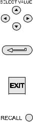
Using This Guide
The following key symbols are used in the procedure diagrams:
Shaded cursor keys indicate that a combination of these four keys, Up, Down, Left and Right should be used to (e.g.) enter an alpha numeric value or to select a function.
Indicates the ENTER key. Used to confirm an operation or a selection. Shading indicates key operation.
Exit key, used to clear current menu selection and return to next menu level above current level. Used as an escape key from current operation. Shading indicates key operation.
Hardkey (total 7). Legend beside key symbol indicates function. Shading indicates key operation.
Maximum Instrument Ratings
The following table shows the maximum measurement input ratings of the instrument which should not be exceeded.
|
PRESSURE |
120% FULL SCALE |
|
VOLTAGE |
30 V d.c. |
|
CURRENT |
55 mA d.c. |
Note 1: The display flashes if the input pressure, voltage or current overrange.
Note 2: Max applied voltage for external loop supply = 30V dc (see page 8).
|
INTRODUCTION |
Summary of Functions |
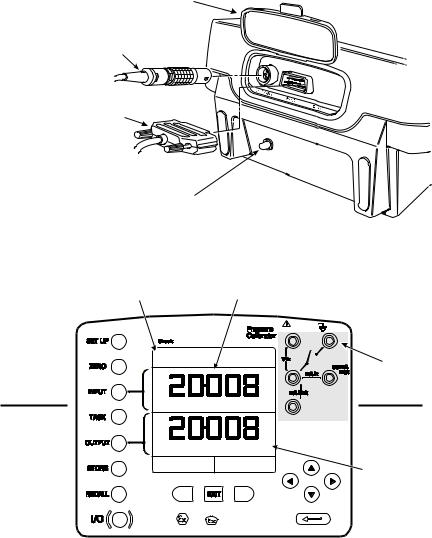
OPERATOR CONTROLS (Figure 1 and 2)
These divide into two groups, the operator/display controls (Figure 1) and the pressure/ vacuum generation components (Figure 2). The operator controls and a typical display, common to all instrument versions, is shown below.
1
 DPI 615 IS
max 30V
|
TASK: BASIC |
||||||
|
2 |
||||||
|
VOLTAGE |
V |
|||||
|
PRESSURE INT |
bar |
|||||
|
CURRENT |
PRESSURE |
|||||
|
UNITS |
||||||
|
3 |
||||||
|
F1 |
F2 |
|||||
|
4 |
||||||
|
7 |
6 |
5 |
||||
|
1 |
Display |
2 Electrical Measurement Input Sockets |
3 |
Cursor Keys |
||
|
4 |
Enter Key |
5 Function (soft) Keys |
6 Hard Keys |
7 |
On/Off Key |
Figure 1 — DPI 610/615 IS Key-pad
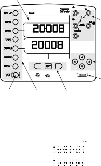
DISPLAY
The display and key-pad of the instrument divides into four distinct sections. The two main sections of the display are used to show an input and an output. The remaining two sections show the status display area and define the soft key functions. A typical display is shown below:
|
Status display |
TASK: BASIC |
|||||||||||||||
|
— + |
||||||||||||||||
|
Input display |
||||||||||||||||
|
VOLTAGE |
V |
|||||||||||||||
|
Output display |
||||||||||||||||
|
PRESSURE INT |
bar |
|||||||||||||||
|
Soft boxes |
CURRENT |
PRESSURE |
||||||||||||||
|
UNITS |

|
INTRODUCTION |
Summary of Functions |
||
|
HARD KEY FUNCTIONS (Fig. 1) |
|||
|
Key |
Function |
Page |
|
|
reference |
|||
|
I/O |
This key selects the instrument ON and OFF. |
7 |
|
|
The SETUP key provides access to the instrument’s general |
36 |
||
|
SETUP* |
configuration parameters that are set-up to certain default |
||
|
parameters on delivery. |
|||
|
The ZERO key zeroes either the selected input or output display, only if |
9 |
||
|
ZERO |
the display reading is within 5% of zero. Attempts to zero a larger |
||
|
offset result in an error message, Zero too large. |
|||
|
INPUT* |
The INPUT key selects the input parameter to be displayed. |
18, 19 |
|
|
The TASK key rapidly configures the instrument for a number of |
10 |
||
|
TASK |
different types of external device calibration. There are twenty task |
||
|
configurations available, eleven pre-programmed configurations and |
|||
|
nine user defined configurations |
|||
|
OUTPUT* |
The OUTPUT key selects the output parameter to be displayed. |
24-27 |
|
|
Depending upon how the instrument’s STORE mode is set-up, this key |
29, 36 |
||
|
STORE* |
is used either to store up to 20 display screens (in SNAPSHOT mode), |
||
|
or to manually log a screen in DATALOG mode. |
|||
|
This key recalls a previously stored screen to the display. Depending |
28, 31, 35 |
||
|
on the STORE mode set-up, operation of this key recalls either the |
|||
|
RECALL* |
snapshot of a previously stored screen or data log file. In STORE |
||
|
mode, selection displays the last screen stored. By using the cursor |
|||
|
keys, the operator can scroll either forward or back through memory |
|||
|
locations. |
|||
|
ENTER |
The ENTER key either enters data (accept entered data), or, in |
2 |
|
|
conjunction with the soft keys, accepts a given selection. |
|||
|
The EXIT key operates in conjunction with all the other hard and soft |
2 |
||
|
EXIT |
keys to exit from the current screen or menu level, to the level |
||
|
immediately preceding it. To quit completely from any menu level, |
|||
|
press EXIT until the MEASURE/SOURCE screen is displayed. |
|||
* These key functions are not available in BASIC mode
|
INTRODUCTION |
Summary of Functions |
SOFT KEYS (Fig. 1)
Three soft keys, designated F1, EXIT and F2, are situated immediately below the display as shown below. These keys have their function allocated by the instrument software which is indicated in the bottom of the display (Voltage for F1 and Units for F2 in this example). They are used to select menu (program) options and are fully described under the appropriate section headings.
CURSOR KEYS (Fig. 1)
The cursor keys consist of a block of four keys, designated up  , down
  , left
  , and right
  . In programs where options need to be selected from a list, (e.g.) the TASK selection program, the up
  and down
  cursor keys are used to highlight one of the options, from which it can be selected by the ENTER key. In TASK mode, where more than one page of options are provided, the left
  , and right
  cursor keys will switch between pages.
3
2
4
1
5
11
6
7
8
9
10
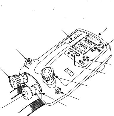
|
1 |
Test port, connect to unit under test |
2 |
Hard keys |
|
3 |
Cover (external interfaces) |
4 |
Electrical inputs |
|
5 |
Cursor keys |
6 |
Function (soft) keys |
|
7 |
Release valve (releases pressure through |
8 |
Vent port |
|
9 |
Select positive or negative pressure |
10 |
Pump |
|
11 |
Fine pressure adjuster |

Figure 2 — DPI 610/615 IS Calibrator Controls
|
INTRODUCTION |
Summary of Functions |
ELECTRICAL CONNECTIONS
1
|
2 |
||
|
1 |
Cover, closed when |
|
|
not using connectors |
||
|
2 |
External transducer |
|
|
3 |
RS232 connector |
3 |
|
4 |
Temperature sensor |
|
USE |
RS232 |
|
IN |
|
|
SAFE |
|
|
AREA |
ONLY |
4
Figure 3 — Electrical System Connections
Measurement inputs and Source outputs are made via the control panel sockets as shown below:
 DPI 615 IS
max 30V CAT II
TASK: BASIC
3
|
INPUTS |
||||
|
VOLTAGE |
V |
|||
|
OUTPUTS |
||||
|
PRESSURE INT |
bar |
|||
|
CURRENT |
PRESSURE |
|||
|
UNITS |
4 |
|||
|
F1 |
F2 |
|||
|
1 |
Status window 2 Input window |
3 |
Electrical measurement input sockets |
|
|
4 |
Output window |
Figure 4 — Electrical Measurement Inputs/Source Outputs

Getting Started
Fitting Batteries
|
1 |
||||||||
|
Manufacturer |
Type No. |
|||||||
|
Energizer |
Industrial Type EN93 |
|||||||
|
Energizer |
Type E93.LR14.C.AM2 |
|||||||
|
Duracell |
Type MN1400-LR14 |
|||||||
|
2 |
||||||||
|
Varta |
No.4014 Type LR14.C.AM2 |
|||||||
|
Procell |
Industrial Type MN1400-LR14 |
|||||||
|
3 |
1 |
Cover fixing |
||||||||||||
|
screws. |
||||||||||||||
|
TASK: BASIC |
2 |
Six alkaline C |
||||||||||||
|
— + |
||||||||||||||
|
cells, see table. |
||||||||||||||
|
Only use the |
||||||||||||||
|
VOLTAGE |
V |
battery type in |
||||||||||||
|
the table. |
||||||||||||||
|
3 |
Low battery |
|||||||||||||
|
bar |
||||||||||||||
|
PRESSURE INT |
indication. |
|||||||||||||
|
CURRENT |
PRESSURE |
|||||||||||||
|
UNITS |
WARNING: BATTERIES MUST ONLY BE FITTED IN A SAFE AREA. USE ONLY THE BATTERIES SPECIFIED IN THE TABLE.
Caution: Old batteries can leak and cause corrosion. Never leave discharged batteries in the instrument. Old batteries should be treated as hazardous waste and disposed of accordingly.
Switching On
Press the I/O switch on the front panel and proceed as follows:
The first time that the instrument is powered up, it will power-up in BASIC mode with the main screen displaying voltage in the input display area and pressure in the source display area. To switch to Current as input, press F1 as shown. Similarly, F1 to return to
Voltage.
Note: No other keys are active in this mode and the instrument can only be reconfigured by pressing the TASK key and selecting another mode.
Getting Started
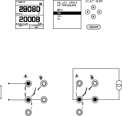
Change Pressure Units
To change the pressure units proceed as follows. If the four units displayed are not the units required, press TASK and select any task, other than BASIC, press SETUP and proceed as detailed on page 36. To return to BASIC mode, press TASK and select BASIC.
In BASIC mode, the unit is configured to carry out basic Pressure to Voltage (P to V) or Pressure to Current (P to I) tests, a typical test procedure follows:
Voltage and Current Measurements
Connect the electrical input sockets as follows for voltage and current measurements. Use the test leads provided and DO NOT push bare wires into the sockets.
|
max 30V |
max 30V |
— |
||||
|
+ |
||||||
|
V |
Vin |
Vin |
+ |
|||
|
55mA |
55mA |
|||||
|
— |
mA in |
max |
mA in |
max |
||
|
mA Sink |
mA Sink |
|
Voltage |
Current |
|
Maximum applied voltage = 30V dc. |
Maximum input current = 55mA dc (at 30 V dc) |
Getting Started
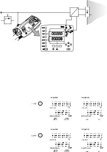
Typical Calibration Set-up (Pressure to Voltage)
Connect a device under test to the instrument as shown below:
C
V
+ —
|
B |
DPI 615 IS |
Max 30V |
|
|
CAT II |
|||
|
TASK: BASIC |
|||
|
VOLTAGE |
V |
||
|
PRESSURE INT |
bar |
||
|
CURRENT |
PRESSURE |
||
|
UNITS |
|||
|
F1 EXIT |
F2 |
D
F
+  +
+
E
—
—
D
A — External pressure source (indicator instruments only) B — Pressure regulator C — Pressure/voltage device D — Barrier E — Excitation 10V F — Safe area
•General Procedure
Use the hand-pump to pressurize the system to the required level as indicated on the display. Allow the display to settle and screw the volume adjuster in or out as a fine adjustment to the required pressure. Record the input: Voltage, reading at each applied pressure.
Zero Display Reading
Both the input and output readings can be set to zero by using the ZERO key and if the displayed reading is within 5% of zero. To zero either the INPUT or OUTPUT displays, proceed as follows:
Task Selection
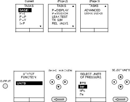
Task Key
The TASK key is used to set-up the instrument for a number of specific types of test. There are two modes BASIC and ADVANCED and nine other specific types of test which automatically configure the instrument on selection from the TASK menu. The tasks available under the TASK menu are held on three pages shown below. To select a task from the menu, press the TASK key, position the cursor over the required task and press the ENTER key as shown below. Use the right/left cursor keys to switch between pages.
Using TASK Functions
Specific tasks are selected as shown above. The following diagrams show how to connect the unit under test (UUT) for each task selectable under the TASK menu.
Input and output units, where applicable, can be selected by pressing either the INPUT or OUTPUT keys as shown below.
Set Units
Note: If the four units displayed are not the units required, press SETUP, select SETTINGS and refer to select regular units on page 37.
![]()
Task Selection
Cal Mode (DPI 615 versions only)
Cal mode, which is available in tasks P-I, P-P, P-V, P-P, P-DISPLAY and P-SWITCH, provides a method of setting up test parameters manually. Downloaded test procedures can also automatically set up and turn on the Cal Mode function. The method of turning on and setting up Cal Mode is shown below for a P-I task. A similar method can be used for all the other tasks applicable to the Cal Mode function.
|
………. |
………. |
|||||||
|
TASK : P-I |
24V OFF |
P |
I |
TASK : P-I |
24V OFF |
|||
|
SELECT VALUE |
DATALOG |
|||||||
|
DATALOG |
psi |
mA |
||||||
|
0.00 |
= |
4.00 |
||||||
|
mA |
2000.00 |
= |
20.00 |
mA |
||||
|
OUTPUT |
= |
LINEAR |
. |
%span FAIL |
||||
|
MAX. ERROR = |
0.05% |
|||||||
|
ERROR TYPE = |
% span |
|||||||
|
psi |
psi |
|||||||
|
TURN ON |
CHANGE |
TURN OFF |
||||||
|
CAL MODE |
VALUE |
CAL MODE |
Pressing the F1 key (TURN ON CAL MODE), provides the set-up screen for the CAL mode. Initially, the cursor is placed in the UUT SPAN field to allow the required span range to be entered. The corresponding values for the UUT output parameter (current) are then set, followed by the maximum error value and error type (%rdg or % span). When all test parameters have been set-up, the screen changes to display the input and output and the test results. The test result can only be displayed to within a range of ±9.99%. If the test result is outside this range, either the left pointing (-ve error) or right pointing (+ve error) chevrons are displayed. Within this error band, the actual tolerance value is displayed. Test results can either be stored as snapshots or logged as data log files, depending on how the instrument has been set-up.
Basic Mode (Task BASIC)
This instrument will power-up in this mode the first time that it is used. To select BASIC from any other task, press the TASK key and select BASIC and press the ENTER key. BASIC mode is fully described in the Getting Started, section (see page 7).
Taking Measurements
Pressure Transmitter (P-I) Task
Select the P-I task from the task menu and connect the Unit Under Test (UUT) to the calibrator as shown below:
|
D |
||||
|
C |
F |
|||
|
+ |
||||
|
+ |
||||
|
P |
E |
|||
|
A |
||||
|
I |
— |
|||
|
— |
||||
|
Max 30V |
||||
|
DPI 615 IS |
CAT II |
|||
|
D |
||||
|
B |
TASK : P-I |
|||
|
SNAPSHOT MODE |
||||
|
CURRENT |
mA |
|||
|
PRESSURE INT |
bar |
|||
|
F1 EXIT |
F2 |
A — External pressure source (indicator instruments only) B — Pressure regulator C — Pressure to current device D — Barrier E — External supply F — Safe Area
•If required, select the output units as described on page 10.
•If applicable, turn on Cal Mode and set-up test parameters as detailed on page 11.
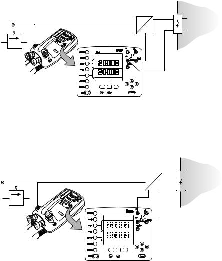
Voltage Output Pressure Transmitter (P-V) Task
Select the P-V task from the task menu and connect the Unit Under Test (UUT) to the instrument as shown below:
D
C F
|
P |
+ |
+ |
||||
|
E |
||||||
|
V |
— |
|||||
|
— |
+—
D
Max 30V
CAT II
TASK: BASIC
|
VOLTAGE |
V |
|||||||||
|
PRESSURE INT |
bar |
|||||||||
|
CURRENT |
PRESSURE |
|||||||||
|
UNITS |
||||||||||
|
F1 |
EXIT |
F2 |
||||||||
A — External pressure source (indicator instruments only) B — Pressure regulator C — Pressure to voltage device D — Barrier E — External supply F — Safe Area
•If required, select the output units as described on page 10.
•If applicable, turn on Cal Mode and set-up test parameters as detailed on page 11.
Taking Measurements
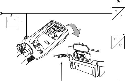
Pressure Converter (Pressure to Pressure) Task
Select the P-P task from the task menu and connect the Unit Under Test (UUT) to the calibrator as shown below. Testing a converter requires one pressure to be applied to the unit under test (UUT) and another (converter output) to be measured. The additional measurement is provided by the external transducer option.
Method
•Connect the UUT to the instrument as shown below. Plug the external transducer into the instrument as shown below:
C
A
D
 3
3
B
E
USE RS232
IN SAFE
AREA ONLY
|
A — External pressure source (indicator instruments only) |
B — Pressure regulator |
|
|
C — External pressure source |
D — Pressure to pressure device E — External transducer |
•Press the TASK key and select the P-P task. Providing the external transducer has been calibrated and its parameters stored in the instrument, the display will show External pressure in the input window and calibrator Output pressure in the output window. If an error message “NO SENSOR OR CAL INVALID” is displayed, this indicates that the external transducer has not been entered and/ or calibrated with the instrument. Refer to page 56 for details of adding an external transducer. If an external transducer change is made, switch the calibrator off and then on to load new transducer data.
•If required, select the input and output units as described on page 10.
•If applicable, turn on Cal Mode and set-up test parameters as detailed on page 11.
Taking Measurements
Current to Pressure Converter (I-P) Task
|
C |
|||||
|
A |
|||||
|
D |
|||||
|
— |
— |
||||
|
P |
E |
||||
|
I |
|||||
|
+ |
+ |
||||
|
B — |
|||||
|
DPI 615 IS |
Max 30V |
C |
|||
|
CAT II |
|||||
|
TASK : I-P |
|||||
|
SNAPSHOT MODE |
|||||
|
PRESSURE INT |
bar |
||||
|
OUTPUT |
|||||
|
NEW VALUE |
|||||
|
CURRENT |
OK |
mA |
|||
|
F1 |
EXIT |
F2 |
|||
|
A — External pressure source |
B — Pressure to current device (24V) |
C — Barrier |
|||
|
D — Safe area |
E — External supply |
•Use the up  and down
  cursor keys to adjust the loop current to the required value. Alternatively, press ENTER and use cursor keys to enter a finite value. Cursor keys can then be used to nudge the output either up or down.
If required, change pressure units with INPUT key. A flashing CHECK LOOP message indicates either an open circuit supply loop (or no external supply).
Pressure Switch Test (P-SWITCH) Task
|
C |
|||
|
A |
|||
|
B |
|||
|
max 30V |
|||
|
DPI 615 IS |
|||
|
TASK : P-SWITCH |
|||
|
SNAPSHOT MODE |
|||
|
CONTACT STATE |
|||
|
PRESSURE INT |
bar |
||
|
RUN |
|||
|
F1 |
F2 |
||
|
A — External pressure source |
B — Pressure regulator |
C — Pressure switch under test |
•Contact state will be shown on display. When contacts close, buzzer sounds.
•To run switch test, close vent valve and press the RUN (F1) key.
•Using the hand-pump, increase the applied pressure to just below the switch operating point. Screw the volume adjuster in until the switch operates (the operating pressure of the switch is then written to the display).
•Reduce pressure until the switch releases (indicated by the switch symbol). The release pressure is then written to the display and the hysteresis displayed.
Taking Measurements
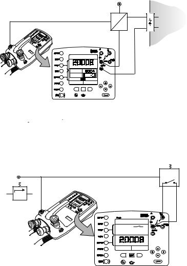
Pressure to Display (P-DISPLAY) Task
P-Display is a special application of Data Log. To use this mode, select Data Log from the Store Mode menu as detailed on page 36. Connect the UUT to the instrument as shown below and, if required, turn on and set-up Cal Mode (see page 11).
|
C |
|
|
max 30V |
|
|
DPI 615 IS |
|
|
TASK : P-DISPLAY |
|
|
SNAPSHOT MODE |
|
|
DISPLAY |
|
|
PRESSURE INT |
bar |
|
CHANGE |
|
|
VALUE |
|
A — External pressure source |
B — Pressure regulator C — Dial gauge under test |
•Press TASK and select P-DISPLAY. If required, use OUTPUT key to change pressure units.
•Set-up a data log file as detailed on page 30.
Note: TRIGGER field, automatically set to KEYPRESS, cannot be changed.
•Apply a series of test pressures to the device under test. Enter displayed reading at each pressure and log each point:
•After logging final test point, terminate as follows:

Taking Measurements
Leak Test (LEAK TEST) Task
A
C
B
max 30V
DPI 615 IS
TASK : LEAK TEST
SNAPSHOT MODE
|
PRESSURE INT |
bar |
|
|
WAIT |
60 |
secs |
|
DURATION |
60 |
secs |
|
START PRESS |
bar |
|
|
STOP PRESS |
bar |
|
|
PRESS CHANGE |
bar |
|
|
LEAK RATE |
bar/m |
|
|
CHANGE |
RUN |
|
|
VALUE |
||
|
F1 |
F2 |
A — External pressure source B — Pressure regulator C — Device/system under test
•If required, use the INPUT key to change pressure units.
•Set-up the leak test WAIT and DURATION times to the required values as shown below. A minimum wait period of 3 minutes is recommended.
•Close the vent valve and pressurize the device/system to the required LEAK TEST pressure.
•Press the RUN (F2) key to start the leak test. When completed, the beeper sounds and the leak test results are written to the display.
Taking Measurements
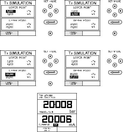
Transmitter Simulator (TX SIM) Task
When used with an external voltage source (see page 24), provides a current output proportional to the calibrator’s measured output pressure (indicated pressure on indicator only version). Select task TX SIM. Press EXIT to skip set-up screen if parameters are correct.
On completion of Tx SIM set-up, the display is configured as follows :.
Connect an external power source to the output loop as detailed on page 24.
To subsequently change any of the Tx SIM scaling parameters, press CHANGE VALUE key (F1) to obtain the TX Simulation set-up display.
To change the pressure units, press INPUT and select the required scale units. If the required scale units are not listed, press SETUP, select SETTINGS and proceed as detailed on page 37.
Taking Measurements
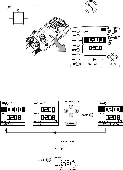
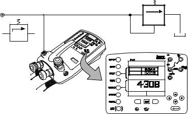
Relief Valve Test (REL VALVE) Task
To carry out a relief valve test, press TASK and select REL VALVE. Connect the output pressure port of the instrument to an external system as shown below:
A C
B
max 30V
DPI 615 IS
TASK : RELVALVE
SNAPSHOT MODE
MAXIMUM
MINIMUM
|
PRESSURE INT |
bar |
|
PRESSURE INT |
bar |
|
RESET |
|
|
MAX/MIN |
|
|
F1 |
F2 |
A — External pressure source (indicator only) B — Pressure regulator C — Relief valve under test
•To change the pressure units, if required, press INPUT and select the required units using the cursor keys.
•Close the vent valve and, using the hand-pump or external pressure supply, apply pressure to the relief valve under test.
•When the relief valve operates, the maximum recorded pressure indicates the operating point of the valve.
•Record the test results.
Note: The STORE key can be used for this purpose. Use right cursor key initially, followed by up/down keys to enter Snapshot text.
•Open vent valve to release test pressure.
Note: If using external pressure supply, isolate supply before opening the vent valve.
Advanced Task |
Select Input |
General
Advanced task allows the user to configure the instrument to monitor one of a number of different input measurements and outputs (sources). Additionally, five process functions, Tare, Max/Min, Filter, Flow and % Span can be applied to the input functions.
Select Input
To select an input channel, select ADVANCED task from the task menu. The display shows the list of the input selections and, if available, the PROCESS soft box (F1) and the UNITS soft box (F2).
The following procedure shows the method of input channel selection and the method of changing units:
Note: Left/right arrow keys function as page up/down keys.
Refer to pages 20 to 23 for details of process functions.
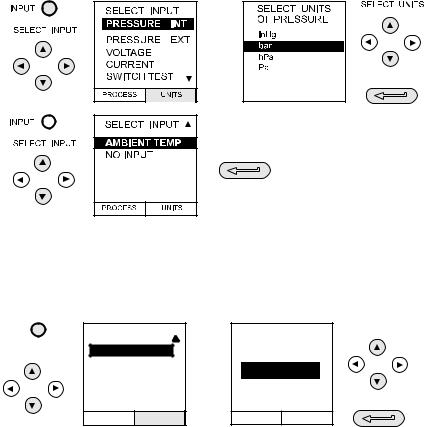
Ambient Temperature Measurement
To set-up the instrument to read ambient temperature, proceed as follows:
|
INPUT |
SELECT INPUT |
SELECT AIR |
SELECT UNITS |
|
TEMPERATURE |
|||
|
SELECT INPUT |
AMBIENT TEMP |
UNITS |
|
|
NO INPUT |
CELSIUS |
||
|
FAHRENHEIT |
PROCESS UNITS
Note: Ensure that the temperature reading has stabilised.
7 сообщений в этой теме
Рекомендуемые сообщения

-
- Жалоба
- Поделиться
В ходе работы в отделе метрологии пришлось столкнуться с регулятором давления Druck DPI 610. Кто-нибудь сталкивался с данным аппаратом? Как им вообще пользоваться?)
- Цитата
Ссылка на комментарий
Поделиться на других сайтах

- Специалисты

- Специалисты
-
- Жалоба
- Поделиться
DPI 610 — это калибратор давления. Как им пользоваться, написано в его руководстве по эксплуатации.
PS. Вот, кстати, Владимир уже выложил.
Изменено 22 Апреля 2019 пользователем su215
- Цитата
Ссылка на комментарий
Поделиться на других сайтах
- Автор
-
- Жалоба
- Поделиться
1 час назад, su215 сказал:
DPI 610 — это калибратор давления. Как им пользоваться, написано в его руководстве по эксплуатации.
PS. Вот, кстати, Владимир уже выложил.
как провести калибровку датчика давления в составе вычислителя ЕК260?
- Цитата
Ссылка на комментарий
Поделиться на других сайтах
-
- Жалоба
- Поделиться
1 час назад, Hammerload сказал:
как провести калибровку датчика давления в составе вычислителя ЕК260?
Что значит «калибровку«? Корректор ЕК260, как правило, используется в сфере ГРОЕИ…
И еще: ЕК-ашки идут с датчиком абсолютного давления. А есть ли у вашего Druck’а возможность воспроизвести абсолютное давление?
- Цитата
Ссылка на комментарий
Поделиться на других сайтах
- Специалисты
- Специалисты
-
- Жалоба
- Поделиться
1 час назад, Hammerload сказал:
как провести калибровку датчика давления в составе вычислителя ЕК260?
По методике калибровки. Если её нет, или написать, или воспользоваться методикой поверки. Скорее всего, речь идёт об этом. Если речь о градуировке (подстройке), то судя по вопросам, у Вас не получится. Связывайтесь с Эльстером.
- Цитата
Ссылка на комментарий
Поделиться на других сайтах
- 3 года спустя…
-
- Жалоба
- Поделиться
Здравствуйте! Подскажите, пожалуйста, код для калибровки( подстройки) параметров калибратора DPI 610. Нужно настроить измерительный канал напряжения.
Простите, нашел руководство и там написан пароль 4321, вопрос снимается ![]()
Изменено 13 Октября 2022 пользователем AECCserg
решено
- Цитата
Ссылка на комментарий
Поделиться на других сайтах
Присоединиться к обсуждению
Вы можете ответить сейчас, а зарегистрироваться позже.
Если у вас уже есть аккаунт, войдите, чтобы ответить от своего имени.

Портативный калибратор давления для калибровки и поверки средств измерения давления

Поставляется в минимальные сроки
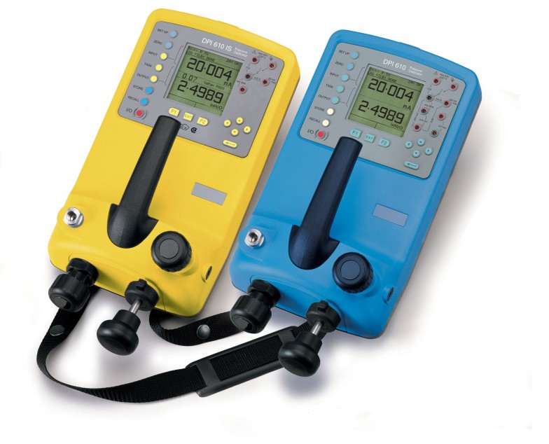
Калибратор давления для калибровки и поверки средств измерения давления
Портативный калибратор давления для калибровки и поверки средств измерения давления: манометров, вакууметров, датчиков избыточного, абсолютного и дифференциального давления. Калибратор работает от батареек / аккумуляторов или сети через адаптер, оснащён встроенной помпой, точной регулировкой давления, есть возможность измерения и генерации выходных электрических параметров и хранения данных. Прочный корпус прибора разработан в соответствии со стандартом IP54. Клавиши защищены от неблагоприятных погодных условий и совмещают в себе высокую чувствительность и долговечность.
На приборы устанавливается второй канал давления, который предназначен для подключений внешних датчиков давления. Калибраторы давления DPI610 обладают возможностью хранения данных и встроенным интерфейсом RS232, уменьшают время проведения калибровок и исключают возможность возникновения ошибок при работе с данными.
Особенности
- Диапазоны измерений давления;
- давления от 0…70 до 0…700 кгс/см²
- давления разрежения от ±0,0025 до 1…35 кгс/см²
- Погрешность измерений давления ±0,025 % (±0,05 % для серии LP) от ВПИ;
- 24 единицы измерения давления: Па, кПа, бар, кгс/см², мм.рт.ст. и др.
- Одновременное измерение давления и электрического сигнала;
- Одновременное воспроизведение тока и измерение тока или напряжения;
- Встроенный источник создания давления (кроме DPI610 I/615 I);
- Степень защиты от пыли и воды IP54;
- Встроенный интерфейс RS232;
- Питание: от встроенного Ni Cd аккумулятора или от сетевого блока питания.
Назначение прибора
- Точное измерение и воспроизведение избыточного, абсолютного давления, разности давлений, давления разрежения, напряжения и силы постоянного тока;
- В качестве эталона при поверке, калибровке, регулировке и градуировке средств измерений давления, вторичных приборов, в т.ч. их калибровке в условиях эксплуатации.
Возможности
- Измерение и воспроизведение электрических сигналов;
- Проверка реле давления с фиксацией значений давления при его срабатывании;
- Тест на герметичность;
- Вычисление погрешности поверяемого датчика (DPI615);
- Питание поверяемого датчика напряжением 24 В;
- Возможность корнеизвлечения при измерении тока;
- Архивирование показаний (до 10 000 значений);
- Показание на ЖКИ значений параметров на входе и выходе в цифровом или графическом виде.
Устройство
Калибраторы давления DPI610 состоят из цифрового манометра со встроенным эталонным модулем давления, встроенного источника создания давления (пневматический насос или гидравлический пресс) и аккумуляторной батареи. Калибратор имеет два канала измерения давления:
- один канал: измерение давления выполняется встроенным модулем давления;
- второй канал: измерение давления выполняется внешним модулем давления (опция).
Калибратор выполнен в виде портативного ручного прибора в пластмассовом корпусе. На лицевой поверхности калибратора размещены клавиатура, жидкокристаллический буквенно-цифровой дисплей (ЖКИ) с размерами 60×60 мм, разъемы для подключения цепей измерения и генерации электрических сигналов, клапан сброса давления, выход для передачи давления на поверяемый прибор через присоединительный шланг.
На нижней поверхности калибратора расположены источник создания давления (пневматический насос или гидравлический пресс), переключатель давление/вакуум (имеется только в пневматических калибраторах, соединен с насосом), вентиль точной настройки. На верхней поверхности калибратора расположен разъем RS232 и разъемы для подключения внешнего модуля давления, блока питания от сети переменного тока (опция). Для удобства эксплуатации калибратор имеет рукоятку и плечевой ремень, который позволяет удерживать калибратор на весу, оставляя руки специалиста свободными.
Принцип действия
Измеряемое давление, созданное источником давления, подается непосредственно на модуль давления и, через соединительный шланг, на поверяемый датчик давления (при необходимости используются переходные штуцеры). Cигнал с выхода эталонного модуля давления после обработки выводится на ЖКИ электронного блока как действительное значение давления, созданное источником давления в рабочей полости поверяемого датчика давления.
Выходной электрический сигнал поверяемого датчика передается в калибратор по измерительным цепям. Значение выходного электрического сигнала поверяемого датчика отображается на табло ЖКИ калибратора.
Технические характеристики Калибратор давления DPI 610
Технические характеристики
| Точность | 0.025% ВПИ для всех диапазонов давления |
| Диапазоны | от -70 … 70 мбар до 0 — 700 бар (изб., абс. и дифф.) |
| встроенный пневматический насос для диапазона от -850 мбар до 20 бар | |
| встроенный гидравлический насос для диапазона от 0 до 400 бар | |
| Измеряемые величины | давление, ток, напряжение, тест реле, окружающая температура |
| Выходные величины | давление, ток |
| Внешние преобразователи давления | 22 номинала преобразователей |
| Единицы измерения давления | 24 стандартных + 1 определенная пользователем |
| Шаг по току | продолжительные импульсы с интервалом в 10 сек |
| Рампирование тока | продолжительный цикл с определяемыми конечными величинами и временем действия в 60 сек |
| Обработка данных | возможность обработки с множеством параметров и сохранением до 10 000 величин |
| Запись результатов | без бумаги, до 20 полных показаний дисплея |
| Интерфейс | RS 232 |
| Функции обработки данных | тарирование, вычисление значений max/min, включение фильтрации показаний, измерение давления расхода, представление величин в процентном соотношении к полному значению шкалы % span |
| Питание | автоматическое отключение питания, автоматическое отключение подсветки, индикатор разряда батарей либо проверка состояния путем выбора из меню |
| Дисплей | размеры: 60 мм * 60 мм графический дисплей на жидких кристаллах с подсветкой. |
| вид показаний: ±99999, 2 показания в секунду | |
| Температура | рабочий диапазон от -10 до 50°С |
| при калибровке от -10 до 40°С | |
| Влажность | 0-90%, неконденсируемая |
| Изоляция | по стандарту IP 54 |
| Сертификаты соответствия | EN61010, EN50081-1, EN50082-1, с отметкой СЕ |
| Источники питания | 6 щелочных элементов по 1,5В типа С (номинальное время работы при температуре в 20°С- 65 ч) |
| Размеры | 300х170х140 мм |
| Масса прибора | 3 кг |
Комплектация калибратора DPI610 PCIS
- Прибор;
- Руководство пользователя.
Дополнительная комплектация калибратора DPI 610 PC IS
- Аккумуляторы и зарядное устройство;
- Внешние преобразователи давления;
- Удлинительные кабели для внешних преобразователей давления;
- Переходник типа 1/8 NPT (гнездо);
- Калибровочное программное обеспечение Linkpak W;
- Грязеуловители.
Отзывы Калибратор давления DPI 610
Пока нет отзывов.
Обсуждение Калибратор давления DPI 610
Пока нет обсуждений.
Specifications:
|
Accompanying Data:
Druck DPI 610 IS Test Equipment PDF Operation & User’s Manual (Updated: Sunday 26th of March 2023 12:37:40 PM)
Rating: 4.6 (rated by 55 users)
Compatible devices: TRX, SGD-TG, DPI620 Genii, G7-1G, S75 PRO, DPI 620 Genii, DCS-2000E SERIES, 140G-G.
Recommended Documentation:
Druck DPI 610 IS: Text of Operation & User’s Manual
(Ocr-Read Version Summary of Contents, UPD: 26 March 2023)
Druck DPI 610 IS: Recommended Instructions
Diffusair, 5224, G-17 Air, T252, IB73100, HRF-340H


-
Safety InstructionsThis unit is designed and manufactured strictly inaccordance with GB4793 safety requirements forelectronic testing meters and IEC61010-1 safetystandards. It fully meets CAT II 600V insulation andovervoltage requirements and Grade II anti-pollutionsafety standards. To prevent personal injuries anddamage of this unit or any other devices connecte …
UTD4000 128
-
OPERATOR’S GUIDE FlexiFrame Stretch & Recovery Instrument Model 1511 Serial Numbers 1511/15/1001 and upwards James H. Heal & Co. Ltd. Halifax, England Publication 290-1511-1$B ©2016 …
FlexiFrame 24
-
MULTIFUNCTION CALIBRATORUser GuideApplies for Main Firmware version 1.90Dear user,We have made every effort to ensure the accuracy of the contents of this manual.Should any errors be detected, we would greatly appreciate to receive suggestionsto improve the quality of the contents of this manual.The above not withstanding, we can assume no responsibility for …
MC5 170
-
Document No.: M-W2906AE-2.0ANRITSU CORPORATION•For safety and warning information, please read thismanual before attempting to use the equipment.•Additional safety and warning information is providedwithin the MD1230B Data Quality Analyzer OperationManual. Please also refer to this document beforeusing the equipment.•Keep this manual with the equipment.MD1230B-26PPPoEOperatio …
MD1230B-26 102
-
ASSOCIATEDMODEL 6054 & 7155GROWLERARMATURE — TESTERSAVE THESE INSTRUCTIONS — This manual contains important safety and operating instructions for the tester you have purchased. You may need to refer to these instructions at a later date.WARNING: RISK OF EXPLOSION This equipment incorporates parts, such as snap switches and probes that tend to produce arc …
6054 2
-
1460-ERidge Tool Company1General Safety InformationWARNING! Read these instructions and the accompanying safety booklet carefully before using this equipment. If you are uncertain about any aspect of using this tool, contact your RIDGID distributor for more information.Failure to understand and follow all instructions may result in electric shock, fi re, and/or …
1460-E 3
-
SicherheitshinweiseLesen Sie bitte vor Inbetriebnahme die Kurzanleitung durch, sie enthält wichtige Hinweise zum korrekten Betrieb.Bei Schäden, die Nichtbeachten dieser Bedienungsanleitung verursacht werden, erlischt die Gewährleistung/Garantie! Für Folgeschäden übernehmen wir keine Haftung!Bei Sach- oder Personenschäden, die durch unsachgemäße Handhabung od …
DSO-6084E 8
-
4822 872 30601 October 2002 Rev. 2, 12/04 © 2002 Fluke Corporation. All rights reserved. Printed in the Netherlands. All product names are trademarks of their respective companies. Fluke 192B — 196B/C — 199B/C ScopeMeter Users Manual …
192B 122
-
RCS : n°447 524 794 00032 – TVA : n°FR13447524794 50-52 Avenue Paul Langevin – F-91130 Ris Orangis – Tel : 01 6902 88 88 / Fax : 01 69 02 04 38 – www.aoip.fr CALYS 1500 Calibrateur de Process Multifonction Multifunction Process Calibrator Mode d’emploi Instruction manual …
CALYS 1500 184
-
Bedienungsanleitung AutostromprüferUser’s Guide Automotive Current TestersInstructions de service Vérificateur courantd’automobileInstrucciones de uso Comprobador de corrientepara cocheInstrução de uso Dispositivo de teste de correntede automóveisIstruzioni per l’uso Tester corrente autoGebruiksaanwijzing AutostroomtesterDriftsvejledning Auto strømmål …
0715 53 090 16
-
Instrukcja obsługi / Operating manual / Инструкция по эксплуатацииAUTODIAGGER 100B+ B- DFM CONTROLРазъемы и подключенияв меню выбора интерфейса служит для изменения указанного интерфейса;нажатие на эту кнопку во время тестиро …
100 2
-
1TBP 500ATTENTION — RISQUE DE GAZ EXPLOSIFS 1. Il est dangereux de travailler à proximité de batteries à l’acide. Les batteries peuvent produire des gaz explosifs pendant leur fonctionnement normal. Pour cette raison, il est extrêmement impor-tant de lire ces instructions avec soin, à chaque fois que vous êtes sur le point d’utiliser cet outil. 2. Pour réduire …
TBP 500 12