-
Contents
-
Table of Contents
-
Bookmarks
Quick Links
Related Manuals for DAF 95XF
Summary of Contents for DAF 95XF
-
Page 1
Maintenance manual 95XF… -
Page 3
E 200424 DAF Trucks N.V., Eindhoven, the Netherlands In the interest of continuing product development, DAF reserves the right to change specification or equipment at any time without notice. No part of this publication may be reproduced and/or published by printing, photocopying, microfilming or by any other means without the manufacturer’s prior permission in writing. -
Page 5
STRUCTURE 95XF series TECHNICAL DATA THREADED CONNECTIONS FLUIDS, OIL AND LUBRICANTS MAINTENANCE SCHEDULE EXPLANATORY NOTES ON THE MAINTENANCE ACTIVITIES 200424… -
Page 7
TECHNICAL DATA 95XF series Contents CONTENTS Page Date XF/XE ENGINE ………… -
Page 8
TECHNICAL DATA 95XF series Contents 200424… -
Page 9: Technical Data
TECHNICAL DATA 95XF series XF/XE engine 1. XF/XE ENGINE 1.1 GENERAL Valve clearance Valve clearance (cold/warm): inlet 0.45 mm exhaust 0.45 mm DEB setting 1.40 mm V-belt tension Belt tension “12.5–mm” V-belts in Newtons (N) Multiple V-belt Single V-belt raw-edge…
-
Page 10
TECHNICAL DATA 95XF series XF/XE engine 1.2 TIGHTENING TORQUES Lubrication system Oil drain plug 60 Nm Oil filter 45 Nm Central bolt for centrifugal oil filter 20 Nm Valve cover Valve cover attachment bolts 25 Nm DEB attachment bolts 110 Nm… -
Page 11
TECHNICAL DATA 95XF series VF engine 2. VF ENGINE 2.1 GENERAL Valve clearance (cold) Inlet valve 0.35 mm Exhaust valve 0.70 mm Unit injector Setting value for unit injector (cold) 0.50 — 0.75 mm C-brake Setting value for C-brake (cold) 0.58 mm… -
Page 12
TECHNICAL DATA 95XF series VF engine 2.2 TIGHTENING TORQUES Lubrication system Oil drain plug 135 Nm Oil filter 55 Nm Valve cover Valve cover attachment bolts 12 Nm Lock nut for valve clearance adjusting bolt 55 Nm Unit injector Lock nut for unit injector adjusting bolt… -
Page 13
TECHNICAL DATA 95XF series Gearbox 3. GEARBOX 3.1 TIGHTENING TORQUES Gearbox ZF 8S-151/181 and 16S-151/181/221 Level check/filler plug (A) 60 Nm Drain plug (B) 60 Nm Drain plug (C/D) 60 Nm M3023 ZF 8S-151/181 and 16S-151/181/221 with integrated retarder Drain plug (D) -
Page 14
TECHNICAL DATA 95XF series Gearbox 3.2 FILLING CAPACITIES ZF 16S-181 Filling capacity approx. 13 litres ZF 16S-221 Filling capacity approx. 13 litres ZF 16S-181/221 with integrated retarder Filling capacity approx. 12 litres 200424… -
Page 15: Rear Axle
TECHNICAL DATA 95XF series Rear axle 4. REAR AXLE 4.1 GENERAL Wheel bearing play, 1347 axle 0.025 — 0.25 mm 4.2 TIGHTENING TORQUES Filler and drain plugs/hub plugs (Torx wrench) 85 Nm M24 hexagon U-bolt nut, property class 8 600 Nm*…
-
Page 16
TECHNICAL DATA 95XF series Rear axle 200424… -
Page 17
TECHNICAL DATA 95XF series Retarder 5. RETARDER 5.1 TIGHTENING TORQUES VOITH retarder 133-2 Retarder drain plug 150 Nm Butterfly valve drain plug 65 Nm Retarder dipstick 80 Nm Retarder level check plug 80 Nm Retarder filler plug M18 x 1.5 50 Nm M24 x 1.5… -
Page 18
TECHNICAL DATA 95XF series Retarder 200424… -
Page 19
TECHNICAL DATA 95XF series Brakes 6. BRAKES 6.1 GENERAL Automatic brake adjuster stroke (09N044 axle, 25 — 35 mm FTP-type vehicles) Automatic brake adjuster stroke (other axles) 35 — 40 mm Reverse torque of adjusting bolt 18 Nm 200424… -
Page 20
TECHNICAL DATA 95XF series Brakes 200424… -
Page 21: Steering Gear
TECHNICAL DATA 95XF series Steering gear 7. STEERING GEAR 7.1 GENERAL Maximum steering ball joint axial clearance 1.5 mm 7.2 TIGHTENING TORQUES Retention bolt/nut for universal joint steering box input shaft 30 Nm + 60_ angular displacement* Always replace bolt and nut…
-
Page 22
TECHNICAL DATA 95XF series Steering gear 200424… -
Page 23: Front Axle
TECHNICAL DATA 95XF series Front axle 8. FRONT AXLE 8.1 GENERAL Wheel bearing play 0.025 — 0.25 mm 8.2 TIGHTENING TORQUES Wheel hub lock nut 30 Nm Hub cap bolt 9 Nm Wheel nut (steel/aluminium) 700 Nm Tighten after 100 km…
-
Page 24
TECHNICAL DATA 95XF series Front axle 200424… -
Page 25
TECHNICAL DATA 95XF series Trailing axle 9. TRAILING AXLE 9.1 GENERAL Wheel bearing play 0.025 — 0.25 mm Hub cap sealant Silicone sealant 9.2 TIGHTENING TORQUES Wheel hub lock nut, 09N220 axle 560 Nm Wheel hub lock nut, 09N075 axle… -
Page 26
TECHNICAL DATA 95XF series Trailing axle 200424… -
Page 27
TECHNICAL DATA 95XF series Leading rear axle 09N044 (FTP-type vehicles) 10.LEADING REAR AXLE 09N044 (FTP-TYPE VEHICLES) 10.1 GENERAL Wheel bearing play 0 mm 10.2 TIGHTENING TORQUES The tightening torques stated in this paragraph are different from the standard tightening torques stated in the overview of standard tightening torques. -
Page 28
TECHNICAL DATA 95XF series Leading rear axle 09N044 (FTP-type vehicles) 200424 10-2… -
Page 29
THREADED CONNECTIONS 95XF series Contents CONTENTS Page Date THREADED CONNECTIONS ………. -
Page 30
THREADED CONNECTIONS 95XF series Contents 200424… -
Page 31
THREADED CONNECTIONS 95XF series Threaded connections 1. THREADED CONNECTIONS 1.1 GENERAL The vehicle components are provided with threaded connections, which have been treated with lubricant (dipped threaded connection). Factory-galvanised bolts and nuts are wax-dipped. Black annealed and phosphatised bolts and nuts are oil-dipped. The advantage of… -
Page 32
THREADED CONNECTIONS 95XF series Threaded connections The following applies to all threaded connections (for both new and used vehicles): in the case of standard connections, apply the lubricant before fitting, and retighten in accordance with the standard for dipped bolts;… -
Page 33
COOLANT, OIL AND LUBRICANTS 95XF series Contents CONTENTS Page Date SPECIFICATIONS ……….. . . -
Page 34
COOLANT, OIL AND LUBRICANTS 95XF series Contents 200424… -
Page 35
1.1 GENERAL IN ORDER TO SATISFY THE WARRANTY CONDITIONS AND GUARANTEE THE LIFESPAN, SAFETY AND RELIABILITY OF DAF PRODUCTS, IT IS OF THE UTMOST IMPORTANCE THAT THE CORRECT FLUIDS, OIL AND LUBRICANTS, COOLANT AND FUEL ARE USED, AND THAT THE REQUIRED REPLACEMENT INTERVALS ARE OBSERVED. -
Page 36
COOLANT, OIL AND LUBRICANTS 95XF series Specifications Avoid contact with: — Lubricants — Coolant — Fuel — Clutch fluid In the event of contact with the skin: remove with paper or a cloth, wash with soap and water. If irritation persists, consult a doctor. -
Page 37: Table Of Contents
MAINTENANCE SCHEDULE 95XF series Contents CONTENTS Page Date MAINTENANCE INTERVALS ……….
-
Page 38
MAINTENANCE SCHEDULE 95XF series Contents 200424… -
Page 39
MAINTENANCE SCHEDULE 95XF series Maintenance intervals 1. MAINTENANCE INTERVALS 1.1 MAINTENANCE SCHEDULE The service intervals stated in the maintenance schedule are based on use of the oils and fuels specified by DAF. Maintenance Intermediate X service Y service schedule inspection… -
Page 40: Explanatory Notes On The Maintenance Schedule
MAINTENANCE SCHEDULE 95XF series Maintenance intervals 1.2 EXPLANATORY NOTES ON THE MAINTENANCE SCHEDULE MAINTENANCE GROUP CLASSIFICATION Depending upon the use to which the vehicle is put, the vehicle is placed in maintenance group I, II or III. Maintenance group I Operation on building sites, in quarries, etc.
-
Page 41: Maintenance Schedule
MAINTENANCE SCHEDULE 95XF series Maintenance intervals INTERMEDIATE INSPECTION Intermediate This is the intermediate inspection symbol. inspection Intermediate inspections are based on several visual inspections. When an extended changing interval is applicable to the engine oil (X-service) an intermediate inspection should be carried out.
-
Page 42: Maintenance Intervals Under Special Operating Conditions
1 PTO hour of XF engine = 20 km 1 PTO hour of XE engine = 40 km 1.4 MAINTENANCE INTERVALS UNDER SPECIAL OPERATING CONDITIONS Contact a DAF dealer/main branch or importer for vehicles used in very specific or heavy conditions.
-
Page 43
MAINTENANCE SCHEDULE 95XF series Maintenance activities 2. MAINTENANCE 2.1 OVERVIEW OF MAINTENANCE ACTIVITIES FOR THE FIRST SERVICE INSPECTION Change engine oil Change oil filter Change gearbox oil/transfer gearbox oil Change retarder oil (Voith retarder) Change differential oil Change hub oil… -
Page 44: Overview Of Annual Maintenance Activities
MAINTENANCE SCHEDULE 95XF series Maintenance activities 2.2 OVERVIEW OF ANNUAL MAINTENANCE ACTIVITIES ANNUAL MAINTENANCE ACTIVITIES (Y-SERVICE) ”Correct if necessary after inspection” CAB AND ELECTRICAL SYSTEM Check pedal rubbers Check headlight setting Check fluid level of cab tilting pump Check cab fastening…
-
Page 45
MAINTENANCE SCHEDULE 95XF series Maintenance activities Note: Every 2 years with coolant according to DAF specification 74001. Every 4 years with coolant according to DAF specification 74002. For changing interval, see maintenance schedule in maintenance manual. For changing interval, see maintenance schedule in maintenance manual. -
Page 46: Overview Of Mileage-Dependent Maintenance Activities
MAINTENANCE SCHEDULE 95XF series Maintenance activities 2.3 OVERVIEW OF MILEAGE-DEPENDENT MAINTENANCE ACTIVITIES MILEAGE-DEPENDENT MAINTENANCE ACTIVITIES (X-SERVICE) ”Correct if necessary after inspection” CAB AND ELECTRICAL SYSTEM Clean/renew heater ventilation filter Replaced Clean battery terminals Check/top up battery fluid level ENGINE, COOLING SYSTEM AND FUEL SYSTEM…
-
Page 47
MAINTENANCE SCHEDULE 95XF series Maintenance activities Note: For changing interval, see maintenance schedule in maintenance manual. For changing interval, see maintenance schedule in maintenance manual. When changing the gearbox oil on a gearbox with intarder or an automatic gearbox, the gearbox oil filter must also be replaced. -
Page 48: Overview Of Intermediate Inspection Activities
MAINTENANCE SCHEDULE 95XF series Maintenance activities 2.4 OVERVIEW OF INTERMEDIATE INSPECTION ACTIVITIES INTERMEDIATE INSPECTION ACTIVITIES ”Correct if necessary after inspection” In case of 100,000 km service intervals, an intermediate inspection should take place between the X-service intervals. CAB AND ELECTRICAL SYSTEM…
-
Page 49
EXPLANATORY NOTES ON THE MAINTENANCE ACTIVITIES 95XF series Contents CONTENTS Page Date SAFETY INSTRUCTIONS ………. -
Page 50
EXPLANATORY NOTES ON THE MAINTENANCE ACTIVITIES 95XF series Contents Page Date Drive and chassis 3.30 Checking the clutch fluid level …….. -
Page 51
EXPLANATORY NOTES ON THE MAINTENANCE ACTIVITIES 95XF series Contents Page Date DRAINING AND FILLING ………. -
Page 52
EXPLANATORY NOTES ON THE MAINTENANCE ACTIVITIES 95XF series Contents 200424… -
Page 53: Safety Instructions
EXPLANATORY NOTES ON THE MAINTENANCE ACTIVITIES 95XF series Safety instructions 1. SAFETY INSTRUCTIONS Comply with all the warnings and safety precautions given in this maintenance manual. First read the instructions and warnings on the labels and stickers which are affixed to various components on the vehicle and follow them.
-
Page 54
EXPLANATORY NOTES ON THE MAINTENANCE ACTIVITIES 95XF series Safety instructions To avoid the risk of fire, the engine and its surroundings should be kept free of inflammable fluids. If an engine encapsulation is present, the encapsulation panels must be thoroughly… -
Page 55: Technical Information
DAF reserves the right to make changes without prior notice. Note: Important changes relating to technical…
-
Page 56: Warning Symbol
EXPLANATORY NOTES ON THE MAINTENANCE ACTIVITIES 95XF series General 2.3 WARNING SYMBOL When text is accompanied by the warning symbol shown here, the information provided is essential for the health and personal safety of the mechanic. This warning symbol is also shown if circumstances threaten the safety of the vehicle or could lead to damage to the vehicle.
-
Page 57
All DAF parts and components have been carefully attuned to each other, a decisive factor in ensuring the original DAF quality. It is only logical, therefore, that the original DAF quality can best be maintained if original DAF parts and components are used when replacing parts or components. -
Page 58: Maintenance Guidelines
Particular attention should be paid to components directly related to driving safety. Consult the DAF workshop instructions when welding at and/or drilling in the chassis. Welding to and/or drilling in wrong spots of the chassis will cause the material to weaken.
-
Page 59
EXPLANATORY NOTES ON THE MAINTENANCE ACTIVITIES 95XF series General Always make sure that when welding at the vehicle the alternator wiring and the positive and negative battery leads are disconnected. Position the earth clamp as close as possible to the weld location. The earth… -
Page 60
EXPLANATORY NOTES ON THE MAINTENANCE ACTIVITIES 95XF series General 200424… -
Page 61
EXPLANATORY NOTES ON THE MAINTENANCE ACTIVITIES 95XF series Inspection and adjustment 3. INSPECTION AND ADJUSTMENT 3.1 CHECKING THE PEDAL RUBBERS Check that the pedal rubbers are still securely mounted on the pedal. Check that the pedal rubbers are not worn out and there is still sufficient tread. -
Page 62: Checking The Battery Fluid Level
EXPLANATORY NOTES ON THE MAINTENANCE ACTIVITIES 95XF series Inspection and adjustment 3.2 CHECKING THE BATTERY FLUID LEVEL Avoid sparks and open flames in the vicinity of batteries. Battery acid is an aggressive fluid. In the event of contact with the skin: rinse the skin with plenty of water for a sustained period.
-
Page 63: Inspection And Adjustment, Headlight Setting
EXPLANATORY NOTES ON THE MAINTENANCE ACTIVITIES 95XF series Inspection and adjustment 3.4 INSPECTION AND ADJUSTMENT, HEADLIGHT SETTING Checking the headlight setting Note: In view of the required precision we advise you to use the correct optical and electronic adjustment equipment, and always follow the manufacturer’s instructions and advice.
-
Page 64: Checking The Fluid Level Of The Cab Tilting Pump
EXPLANATORY NOTES ON THE MAINTENANCE ACTIVITIES 95XF series Inspection and adjustment 3.5 CHECKING THE FLUID LEVEL OF THE CAB TILTING PUMP The fluid level must be checked when the cab is tilted back. The cock (2) should be in the “lowering”…
-
Page 65: Inspection And Adjustment, Valve Clearance
Place the fuel pump in the stop position. Lock the fuel pump in this position. Use the special tool (DAF no. 1310477) to turn the crankshaft clockwise, as seen from the timing gear end (this is the engine’s normal direction of rotation), until the valves of cylinder 1 overlap.
-
Page 66
See “Technical data” for the correct valve clearance. M200540 By always cranking the camshaft by 1/3 of a stroke using the special tool (DAF no. 1310477), the valves can be adjusted according to the injection sequence 1-5-3-6-2-4. Valve overlap of Set valves… -
Page 67: Inspection And Adjustment, Deb Clearance
EXPLANATORY NOTES ON THE MAINTENANCE ACTIVITIES 95XF series Inspection and adjustment 3.8 INSPECTION AND ADJUSTMENT, DEB CLEARANCE XF/XE engine Remove the valve covers. Tighten the DEB attachment bolts to the specified torque. See “Technical data”. Crank the engine in the direction of rotation…
-
Page 68: Inspection/Adjustment: Valve Clearance/Unit Injectors
EXPLANATORY NOTES ON THE MAINTENANCE ACTIVITIES 95XF series Inspection and adjustment 3.9 INSPECTION AND ADJUSTMENT, VALVE CLEARANCE AND UNIT INJECTORS VF engine Note: The valve clearances and unit injectors must be adjusted when the engine is cold 60_C). Each cylinder has three rockers:…
-
Page 69
EXPLANATORY NOTES ON THE MAINTENANCE ACTIVITIES 95XF series Inspection and adjustment Disconnect the battery earth lead. Remove the valve covers. See “Removal and installation”. If the vehicle is equipped with a C-brake, the C-brake must be removed first, see chapter “Removal and installation”. -
Page 70
EXPLANATORY NOTES ON THE MAINTENANCE ACTIVITIES 95XF series Inspection and adjustment Rotate the drive pulley (in the direction of rotation of the crankshaft) using the attachment nut on the pulley, until the “A” marking is in line with the marking on the timing cover. -
Page 71
Inspection and adjustment Adjusting the valve clearance Slacken the lock nut of the adjusting bolt. Using a feeler gauge and special tool (DAF no. 1240043), adjust the specified valve clearance, see “Technical data”. Tighten the adjusting bolt using special tool (DAF no. -
Page 72
EXPLANATORY NOTES ON THE MAINTENANCE ACTIVITIES 95XF series Inspection and adjustment Adjusting the unit-injector Slacken the lock nut of the adjusting bolt. Turn the adjusting bolt three to four times clockwise and anti-clockwise. This will force the fuel beneath the injector plunger out, thus moving the injector plunger downwards. -
Page 73: Inspection And Adjustment, C-Brake Play
EXPLANATORY NOTES ON THE MAINTENANCE ACTIVITIES 95XF series Inspection and adjustment 3.10 INSPECTION AND ADJUSTMENT, C-BRAKE PLAY VF engine Note: The C-brake must be adjusted when the engine is cold ( <60°C). Use a dial gauge for C-brake adjustments. Each cylinder has three rockers:…
-
Page 74
EXPLANATORY NOTES ON THE MAINTENANCE ACTIVITIES 95XF series Inspection and adjustment The C-brakes of the specified cylinders can be set using the table below and the marks on the drive pulley and on the timing cover. Marks on drive pulley:… -
Page 75
The setting value is also shown on the shield (1) fitted on the C-brake housing. 10. Tighten the lock nut to the specified tightening torque. See “Technical data”. Use special tool (DAF no. 1240042). M2152 11. Repeat this adjustment procedure for the remaining cylinders. Consult the following table to this end. -
Page 76: Inspection And Adjustment, V-Belt Tension
3.11 INSPECTION AND ADJUSTMENT, V-BELT TENSION XF/XE engine Checking the V-belt tension Check the V-belt tension using special tool (DAF no. 1240442) for the single V-belts and using special tool (DAF no. 1240443) for the multiple V-belts or poly V-belts. M2079 Set the gauge to zero by depressing the measuring arm (1).
-
Page 77
EXPLANATORY NOTES ON THE MAINTENANCE ACTIVITIES 95XF series Inspection and adjustment Take the reading as indicated by the position of the measuring arm in relation to the scale. Compare this reading with the recommended pre-tension figure. See “Technical data”. M2062 … -
Page 78
EXPLANATORY NOTES ON THE MAINTENANCE ACTIVITIES 95XF series Inspection and adjustment Adjusting the V-belt tension of the air conditioning compressor drive Loosen the upper attachment bolt (1) on the compressor. Loosen the lower attachment bolt (2) on the compressor. Loosen the attachment bolt from the threaded spindle which is attached to the coolant pump. -
Page 79
Inspection and adjustment VF ENGINE Checking the V-belt tension Check the V-belt tension using special tool (DAF no. 1240442) for the single V-belts and using special tool (DAF no. 1240443) for the multiple V-belts or poly V-belts. M2079 Set the gauge to zero by depressing the measuring arm (1). -
Page 80
EXPLANATORY NOTES ON THE MAINTENANCE ACTIVITIES 95XF series Inspection and adjustment Adjusting the V-belt tension of the air conditioning compressor drive Slacken the attachment bolt (1) in the clamping block (2) and slacken the attachment bolt of the threaded spindle on the cylinder block. -
Page 81: Checking The Antifreeze Content In The Cooling System
EXPLANATORY NOTES ON THE MAINTENANCE ACTIVITIES 95XF series Inspection and adjustment 3.12 CHECKING THE ANTIFREEZE CONTENT IN THE COOLING SYSTEM When the coolant is hot, there is an overpressure in the cooling system. Carefully remove the filler cap to release the overpressure.
-
Page 82
EXPLANATORY NOTES ON THE MAINTENANCE ACTIVITIES 95XF series Inspection and adjustment 3.13 CHECKING THE RACOR FILTER ELEMENT FOR WATER SEPARATION If necessary, open drain plug (8) and pump the water out using the feed pump (1). Close the drain plug (8). -
Page 83: Bleeding The Fuel System
EXPLANATORY NOTES ON THE MAINTENANCE ACTIVITIES 95XF series Inspection and adjustment 3.15 BLEEDING THE FUEL SYSTEM Bleeding the fuel system with Racor filter While bleeding the fuel system, fuel will escape. Collect this fuel, bearing in mind the risk of fire.
-
Page 84
EXPLANATORY NOTES ON THE MAINTENANCE ACTIVITIES 95XF series Inspection and adjustment Bleeding the XF engine fuel system While bleeding the fuel system, fuel will escape. Collect this fuel, bearing in mind the risk of fire. Open the bleed screw (1) on the filter housing. -
Page 85
EXPLANATORY NOTES ON THE MAINTENANCE ACTIVITIES 95XF series Inspection and adjustment 3.16 CHECKING THE GLOW COILS Note: To avoid engine damage it is important that the glow coils be checked periodically. Check the glow coils for the following points: windings that have worn thin due to abrasion (A);… -
Page 86: Checking The Radiator And Intercooler For Fouling
EXPLANATORY NOTES ON THE MAINTENANCE ACTIVITIES 95XF series Inspection and adjustment 3.17 CHECKING THE RADIATOR AND INTERCOOLER FOR FOULING Visually inspect the radiator and intercooler for fouling. If required, clean the radiator and intercooler, see “Cleaning”. 3.18 CHECKING THE STEERING OIL LEVEL…
-
Page 87: Checking The Steering Gear Pipes And Connections
EXPLANATORY NOTES ON THE MAINTENANCE ACTIVITIES 95XF series Inspection and adjustment 3.19 CHECKING THE STEERING GEAR PIPES AND CONNECTIONS Condition of the pipes Check all pipes for tightness and wear. When one or more supply pipes is subject to negative pressure, it is especially likely that porous pipes will give rise to faults (air in the system).
-
Page 88: Checking The Steering Ball Joints
S700430 Checking the axial steering ball joint play Check the axial steering ball joint play using the special tool (DAF no. 1329426). First jack up the axle until the wheels come off the ground and put the axle on stands.
-
Page 89: Checking The Brake Components/Brake System For Leaks
EXPLANATORY NOTES ON THE MAINTENANCE ACTIVITIES 95XF series Inspection and adjustment Measure the play “A” between the thrust sleeve and the bracket using a feeler gauge. Compare the measured play with the maximum allowable steering ball joint play. See “Technical data”.
-
Page 90: Checking The Brake Lining Thickness
EXPLANATORY NOTES ON THE MAINTENANCE ACTIVITIES 95XF series Inspection and adjustment 3.22 CHECKING THE BRAKE LINING THICKNESS Checking the brake lining thickness (FTP axle excepted) Pressurise the air brake system (pressure switch should cut out) and make sure that the vehicle’s parking brake is not activated.
-
Page 91
EXPLANATORY NOTES ON THE MAINTENANCE ACTIVITIES 95XF series Inspection and adjustment 3.23 CHECKING THE BRAKE CYLINDER FASTENING Check that the brake cylinders do not move during operation of the service brake. 200424 3-31… -
Page 92: Checking The Automatic Brake Adjuster
EXPLANATORY NOTES ON THE MAINTENANCE ACTIVITIES 95XF series Inspection and adjustment 3.24 CHECKING THE AUTOMATIC BRAKE ADJUSTER Checking the brake adjuster travel Measure the basic setting L1. Measure the position when the brakes are applied, L2 (minimum brake system pressure 6 bar).
-
Page 93
EXPLANATORY NOTES ON THE MAINTENANCE ACTIVITIES 95XF series Inspection and adjustment 3.25 INSPECTION AND ADJUSTMENT, LOAD-DEPENDENT CONTROL VALVE, LEAF SUSPENSION Explanatory notes on instruction plate 1261660 The instruction plate contains details of the axle TYPE — TIPO : FA loads and output pressures; these correspond to AUTOM. -
Page 94
EXPLANATORY NOTES ON THE MAINTENANCE ACTIVITIES 95XF series Inspection and adjustment Depress the brake pedal until pressure gauge (1) reads 6 bar and read off the braking pressure of the rear axle on pressure gauge (2). Compare this value with the data in the table attached to the door pillar. -
Page 95: Air Suspension
EXPLANATORY NOTES ON THE MAINTENANCE ACTIVITIES 95XF series Inspection and adjustment 3.26 INSPECTION AND ADJUSTMENT, LOAD-DEPENDENT CONTROL VALVE, AIR SUSPENSION Explanatory notes on instruction plate 1263639 The information contained on the instruction TYPE — TIPO : FA plate relates to the axle loads, the output AUTOM.
-
Page 96
EXPLANATORY NOTES ON THE MAINTENANCE ACTIVITIES 95XF series Inspection and adjustment Set the simulated bellows pressure at its highest value, as indicated on the instruction plate. Depress the brake pedal until pressure gauge (4) indicates a pressure of 6 bar. -
Page 97: Checking The Electropneumatic Valves Of Abs/Asr
EXPLANATORY NOTES ON THE MAINTENANCE ACTIVITIES 95XF series Inspection and adjustment 3.27 CHECKING THE ELECTROPNEUMATIC VALVES OF ABS/ASR Ensure there is an adequate air supply. Connect a pressure gauge to the brake cylinder of the wheels to be tested. Fully depress the brake pedal. The pressure…
-
Page 98: Checking The Compressor Line
EXPLANATORY NOTES ON THE MAINTENANCE ACTIVITIES 95XF series Inspection and adjustment 3.28 CHECKING THE COMPRESSOR LINE Remain at a safe distance from rotating and/or moving components. Note: When measuring excessive values, the inside of the air dryer housing and the silencer on the exhaust should first be cleaned.
-
Page 99
EXPLANATORY NOTES ON THE MAINTENANCE ACTIVITIES 95XF series Inspection and adjustment Run the engine at idling speed. 10. Blow off the brake system until the cut-in pressure of the pressure regulator is reached and switch off the engine. The indicator on the pressure gauge should not drop rapidly. -
Page 100
EXPLANATORY NOTES ON THE MAINTENANCE ACTIVITIES 95XF series Inspection and adjustment 3.29 CHECKING THE ATTACHMENT OF THE UNIVERSAL JOINT OF THE STEERING BOX INPUT SHAFT Checking the attachment of the universal joint of the steering box input shaft Check the universal joint for noticeable play. -
Page 101: Checking The Clutch Fluid Level
EXPLANATORY NOTES ON THE MAINTENANCE ACTIVITIES 95XF series Inspection and adjustment 3.30 CHECKING THE CLUTCH FLUID LEVEL Hydraulic fluid is toxic and can have a damaging effect on your health. It is therefore important to avoid inhalation and direct contact.
-
Page 102: Checking The Hgs Fluid Level
EXPLANATORY NOTES ON THE MAINTENANCE ACTIVITIES 95XF series Inspection and adjustment 3.31 CHECKING THE HGS FLUID LEVEL Hydraulic fluid is toxic and can have a damaging effect on your health. It is therefore important to avoid inhalation and direct contact.
-
Page 103
EXPLANATORY NOTES ON THE MAINTENANCE ACTIVITIES 95XF series Inspection and adjustment 3.32 CHECKING THE OIL AND GREASE LUBRICATED HUBS FOR LEAKS If leaks occur in oiled wheel hubs, the wheel hub should be refilled to the correct level – once the leak has been repaired –… -
Page 104: Checking The Operation Of The Differential Lock
EXPLANATORY NOTES ON THE MAINTENANCE ACTIVITIES 95XF series Inspection and adjustment 3.37 CHECKING THE OPERATION OF THE DIFFERENTIAL LOCK Jack up the rear axle and support it on stands. Bring the air system to operating pressure. Engage the differential lock. The warning lamp should now come on.
-
Page 105: Checking The Pivots Of The Axle Suspension, Air Suspension
EXPLANATORY NOTES ON THE MAINTENANCE ACTIVITIES 95XF series Inspection and adjustment 3.39 CHECKING THE PIVOTS OF THE AXLE SUSPENSION, AIR SUSPENSION Torque rod Check the attachment of the torque rod and torque rod supports. Check the pivots of the torque rod for wear and play.
-
Page 106
EXPLANATORY NOTES ON THE MAINTENANCE ACTIVITIES 95XF series Inspection and adjustment 3.40 CHECKIGN THE DRIVE SHAFT PLAY Check the universal joints and centre bearing for play and damage. M3032 Check the sliding clutch for axial and radial play. M3019 There must be no clearly noticeable play on universal joints, centre bearing or sliding clutch. -
Page 107: Checking The Air Suspension Bellows
EXPLANATORY NOTES ON THE MAINTENANCE ACTIVITIES 95XF series Inspection and adjustment 3.41 CHECKING THE AIR SUSPENSION BELLOWS Raise the chassis to its highest position using the remote control. Clean the air bellows using a cleaning rag or a soap solution, if required.
-
Page 108
EXPLANATORY NOTES ON THE MAINTENANCE ACTIVITIES 95XF series Inspection and adjustment 3.43 CHECKING THE FIFTH WHEEL Check the attachment of the fifth wheel. Check the play of the closing gear of the fifth wheel. Note: For maximum play values, consult the manufacturer’s instructions or the legal… -
Page 109: Checking The Trailer Coupling
EXPLANATORY NOTES ON THE MAINTENANCE ACTIVITIES 95XF series Inspection and adjustment 3.44 CHECKING THE TRAILER COUPLING Check the upward play of the arched pin. Check the radial play of the arched pin. M9002 Check the vertical and horizontal play of the coupling jaw.
-
Page 110
Select the split pin hole where the hub nut needs to be turned back least. Fit the hub cap. Tighten the hub cap to the specified torque using the special tool (DAF no. 1329498). See “Technical data”. Adjust the brakes. -
Page 111: Inspection And Adjustment, Wheel Bearing Play
FRONT AXLE/TRAILING AXLE 09N075/LEADING REAR AXLE Checking the wheel bearing play To make sure that the inspection of the wheel bearing play is reliable, use the special tool (DAF no. 0535595). The special tool consists of: extensions central nut dial gauge holder…
-
Page 112
EXPLANATORY NOTES ON THE MAINTENANCE ACTIVITIES 95XF series Inspection and adjustment Fit the central nut (2) to the axle journal using the socket wrench (6). If the length of screw thread protruding from the lock nut is not enough to fit the central nut (2) to the axle journal, remove the lock nut from the axle journal. -
Page 113
EXPLANATORY NOTES ON THE MAINTENANCE ACTIVITIES 95XF series Inspection and adjustment Place a torque wrench on the hexagon 40Nm head of the spindle (4). Press the hub firmly onto the axle journal by screwing the spindle in, until a tightening torque of 40 Nm is reached. -
Page 114
EXPLANATORY NOTES ON THE MAINTENANCE ACTIVITIES 95XF series Inspection and adjustment Adjusting the wheel bearing play Use a socket wrench (A), special tool (DAF no. 0535832), to remove the lock nut from the axle journal. Remove the lock plate and the circlip from the axle journal. -
Page 115
EXPLANATORY NOTES ON THE MAINTENANCE ACTIVITIES 95XF series Inspection and adjustment The specified wheel-bearing play is achieved by turning the adjusting nut (1) counter-clockwise between 45° and 60° (distance A — B in the drawing) using the adjusting spanner (A). The precise angle should be such that the circlip (2) can be fitted. -
Page 116
Fit the hub cap. Tighten the hub cap to the specified torque using the special tool (DAF no. 1329498). See “Technical data”. Adjust the brakes. S7 00 635… -
Page 117
Fit the hub cap. Tighten the hub cap to the specified torque using the special tool (DAF no. 1329498). See “Technical data”. 10. Adjust the brakes. -
Page 118
EXPLANATORY NOTES ON THE MAINTENANCE ACTIVITIES 95XF series Inspection and adjustment Fit the central nut (2) to the axle journal using the socket wrench (6). Place the dial gauge in the dial gauge holder (3) so that the stylus abuts the hub. -
Page 119
Mark these two nuts and tighten them after 100 km. Adjusting the wheel bearing play Use a special tool (DAF no. 0535648) to remove the lock nut from the axle journal. Remove the lock plate and the circlip from the axle journal. -
Page 120: Checking The Wheel Hub And Wheel Bearings
EXPLANATORY NOTES ON THE MAINTENANCE ACTIVITIES 95XF series Inspection and adjustment 3.47 CHECKING THE WHEEL HUB AND WHEEL BEARINGS Inspect the bearings for damage at the following points: the roller bearing race, the bearing cage, the raceways of the inner and outer race.
-
Page 121: Removal And Installation
EXPLANATORY NOTES ON THE MAINTENANCE ACTIVITIES 95XF series Removal and installation 4. REMOVAL AND INSTALLATION 4.1 REMOVAL AND INSTALLATION, INTERIOR FILTER ELEMENT Removing the interior filter element Open the grille. Remove the attachment bolts (1) at the bottom of the filter.
-
Page 122: Removal And Installation, Oil Filter
EXPLANATORY NOTES ON THE MAINTENANCE ACTIVITIES 95XF series Removal and installation 4.2 REMOVAL AND INSTALLATION, OIL FILTER To prevent skin injury, avoid unnecessary contact with the drained oil. XF/XE engine Removing the oil filter Place a tray beneath the filter.
-
Page 123
EXPLANATORY NOTES ON THE MAINTENANCE ACTIVITIES 95XF series Removal and installation VF engine Removing the oil filter Place a tray beneath the filter. Remove the filter by turning it counter-clockwise using special tool (DAF no. 1240115). Note: The oil filter is a disposable filter, and may not be cleaned and reused. -
Page 124: Removal And Installation, Centrifugal Oil Filter Rotor
EXPLANATORY NOTES ON THE MAINTENANCE ACTIVITIES 95XF series Removal and installation 4.3 REMOVAL AND INSTALLATION, CENTRIFUGAL OIL FILTER ROTOR To prevent skin injury, avoid unnecessary contact with the drained oil. Removing the centrifugal oil filter rotor Clean the housing (3).
-
Page 125: Removal And Installation, Air Filter Element
EXPLANATORY NOTES ON THE MAINTENANCE ACTIVITIES 95XF series Removal and installation 4.4 REMOVAL AND INSTALLATION, AIR FILTER ELEMENT Removing the air filter element Loosen the retaining clamps (1) on the air filter cover (2). Remove the air filter cover. Remove the air filter element (3).
-
Page 126: Removal And Installation, Fuel Filter
EXPLANATORY NOTES ON THE MAINTENANCE ACTIVITIES 95XF series Removal and installation 4.5 REMOVAL AND INSTALLATION, FUEL FILTER When removing the fuel filter, a quantity of fuel will escape. Collect the fuel to avoid the risk of fire. XF/XE engine Removing the fuel filter Place a tray beneath the filter.
-
Page 127
EXPLANATORY NOTES ON THE MAINTENANCE ACTIVITIES 95XF series Removal and installation VF engine Removing the fuel filters Place a tray beneath the filters to capture any escaping fuel. Remove the filters by turning them counter-clockwise. Note: The fuel filter is a disposable filter, and must not be cleaned and reused. -
Page 128: Removal And Installation, Racor-Filter Element
EXPLANATORY NOTES ON THE MAINTENANCE ACTIVITIES 95XF series Removal and installation 4.6 REMOVAL AND INSTALLATION, RACOR-FILTER ELEMENT When removing the Racor filter element, fuel will escape. Collect the fuel to avoid the risk of fire. Removing the Racor filter element…
-
Page 129: Removal And Installation, Fuel Coarse Filter
EXPLANATORY NOTES ON THE MAINTENANCE ACTIVITIES 95XF series Removal and installation 4.7 REMOVAL AND INSTALLATION, FUEL COARSE FILTER A quantity of fuel will escape when the fuel coarse filter is removed. Collect the fuel to avoid the risk of fire.
-
Page 130: Removal And Installation, Coolant Filter
EXPLANATORY NOTES ON THE MAINTENANCE ACTIVITIES 95XF series Removal and installation 4.8 REMOVAL AND INSTALLATION, COOLANT FILTER When the coolant is hot, there is an overpressure in the cooling system. Carefully remove the filler cap to release the overpressure. Coolant is a toxic fluid. Contact with the skin should therefore be avoided.
-
Page 131
EXPLANATORY NOTES ON THE MAINTENANCE ACTIVITIES 95XF series Removal and installation VF engine Removing the coolant filter ”ON” Place a tray beneath the coolant filter to collect any escaping coolant. Remove the filler cap from the expansion tank. Switch the shut-off valve to the “OFF”… -
Page 132: Removal And Installation, V-Belt
EXPLANATORY NOTES ON THE MAINTENANCE ACTIVITIES 95XF series Removal and installation 4.9 REMOVAL AND INSTALLATION, V-BELT XF/XE engine Adjusting the V-belt tension of the water pump and alternator drive Slacken the alternator bracket attachment bolts (1) and (2). Loosen the attachment bolt (3) of the threaded spindle that is fixed to the water pump.
-
Page 133
EXPLANATORY NOTES ON THE MAINTENANCE ACTIVITIES 95XF series Removal and installation Removing the V-belt of the air-conditioning compressor drive Loosen the lower attachment bolt (1) of the alternator. Loosen the upper attachment bolt (2) of the alternator. Loosen the attachment bolt (3) of the threaded spindle that is fixed to the water pump. -
Page 134
EXPLANATORY NOTES ON THE MAINTENANCE ACTIVITIES 95XF series Removal and installation VF engine Removing the V-belt of the air-conditioning compressor drive Slacken the attachment bolt (1) in the clamping block (2) and slacken the attachment bolt of the threaded spindle on the cylinder block. -
Page 135
EXPLANATORY NOTES ON THE MAINTENANCE ACTIVITIES 95XF series Removal and installation Removing the poly V-belt (10-rib) of fan and alternator drive Slacken the attachment bolt (1) in the clamping block (2) and slacken the attachment bolt of the threaded spindle on the cylinder block. -
Page 136: Removal And Installation, C-Brake
EXPLANATORY NOTES ON THE MAINTENANCE ACTIVITIES 95XF series Removal and installation 4.10 REMOVAL AND INSTALLATION, C-BRAKE Removing the C-brake Remove the C-brake connectors on the C-brake housing. Remove the C-brake housing attachment bolts. Installing the C-brake Clean and blow-dry the housing.
-
Page 137: Removal And Installation, Valve Cover
EXPLANATORY NOTES ON THE MAINTENANCE ACTIVITIES 95XF series Removal and installation 4.11 REMOVAL AND INSTALLATION, VALVE COVER XF/XE engine When the engine or parts thereof are opened, it is possible for dirt to penetrate which can result in serious damage to the engine. So clean the engine thoroughly before opening any parts of it.
-
Page 138
EXPLANATORY NOTES ON THE MAINTENANCE ACTIVITIES 95XF series Removal and installation VF engine Removing the valve cover Clean the area around the valve cover. Remove the attachment bolts from the valve cover. Remove the valve cover and the gasket. Installing the valve cover Clean the sealing face of the valve cover. -
Page 139: Removal And Installation, Deb
EXPLANATORY NOTES ON THE MAINTENANCE ACTIVITIES 95XF series Removal and installation 4.12 REMOVAL AND INSTALLATION, DEB Make sure that the spring plate (5) under the main piston (4) is not damaged or deformed. If this spring plate is damaged or…
-
Page 140: Removal And Installation, Steering Gear Filter Element
EXPLANATORY NOTES ON THE MAINTENANCE ACTIVITIES 95XF series Removal and installation 4.13 REMOVAL AND INSTALLATION, STEERING GEAR FILTER ELEMENT Clean the reservoir cover, so that absolutely no dirt can get into the reservoir. Remove the cover (3), turn filter holder (5) a…
-
Page 141: Removal And Installation, Air Dryer Filter Element
EXPLANATORY NOTES ON THE MAINTENANCE ACTIVITIES 95XF series Removal and installation 4.14 REMOVAL AND INSTALLATION, AIR DRYER FILTER ELEMENT Removing the air dryer filter element Remove the compressor line (1); as a result, the inside of the air dryer will become pressureless.
-
Page 142: Removal And Installation, Gearbox Oil Filter
EXPLANATORY NOTES ON THE MAINTENANCE ACTIVITIES 95XF series Removal and installation 4.15 REMOVAL AND INSTALLATION, GEARBOX OIL FILTER To prevent skin injury, avoid unnecessary contact with the drained oil. Gearbox 16S-181/221 with integrated retarder Removing the gearbox oil filter Remove the attachment bolt (1) of the oil filter.
-
Page 143
EXPLANATORY NOTES ON THE MAINTENANCE ACTIVITIES 95XF series Removal and installation Installing the gearbox oil filter Check the O-ring of the filter cover (2) for any damage. Replace the O-ring if necessary. Grease the O-ring. Grease the O-ring of the new filter (3) and place the filter on the filter cover. -
Page 144: Removal And Installation, Wheel Hub
EXPLANATORY NOTES ON THE MAINTENANCE ACTIVITIES 95XF series Removal and installation 4.16 REMOVAL AND INSTALLATION, WHEEL HUB FRONT AXLE/LEADING REAR AXLE/TRAILING AXLE 09N075 11 12 S7 00 401 Removing the wheel hub Jack up the axle until the wheels are clear from the floor and position suitable stands under the axle.
-
Page 145
95XF series Removal and installation Remove the adjusting nut (6) from the axle journal using adjusting spanner (A), special tool (DAF no. 0694783). Remove the outer wheel bearing (7) from the hub (8). Note: If the bearings are removed from both wheels, the bearings should be marked. -
Page 146
EXPLANATORY NOTES ON THE MAINTENANCE ACTIVITIES 95XF series Removal and installation 11 12 S7 00 401 Installing the wheel hub Check the wheel hub and the wheel bearings for wear and damage, see “Inspection and adjustment”. Fit a new wheel speed sensor ring (10) to the hub, if necessary. -
Page 147
EXPLANATORY NOTES ON THE MAINTENANCE ACTIVITIES 95XF series Removal and installation 12. Slide the hub over the axle journal. Do not pry, as the oil seal (14) might be damaged in the process. 13. Fit the adjusting nut (6) to the axle journal. -
Page 148
Adjust the wheel bearing play, see chapter “Inspection and adjustment”. Fit the split pin (2). Lower the leading rear axle. Fit the hub cap using special tool (DAF no. 1329894). Tighten the hub cap to the specified torque, see “Technical data”. Adjust the brakes. -
Page 149
EXPLANATORY NOTES ON THE MAINTENANCE ACTIVITIES 95XF series Removal and installation TRAILING AXLE 09N220 A800267 Removing the wheel hub Remove the attachment bolts from the hub cap and remove the hub cap (4). Lift the trailing axle using the trailing axle load transfer device. -
Page 150
EXPLANATORY NOTES ON THE MAINTENANCE ACTIVITIES 95XF series Removal and installation Note: If the bearings are removed from both wheels, the bearings should be marked. Each bearing should be re-installed in its original hub. Remove the hub with the wheel from the axle journal. -
Page 151
EXPLANATORY NOTES ON THE MAINTENANCE ACTIVITIES 95XF series Removal and installation A800267 Installing the wheel hub Check the hub and the wheel bearings for wear and damage. See chapter “Inspection and adjustment”. Fit new wheel bearings into the hub, if necessary. -
Page 152
14. Fit the lock nut (5) to the axle journal. Tighten the lock nut (5) to the specified tightening torque. See “Technical data”. Use special tool (DAF no. 0535648). 15. Secure lock nut (5) by tapping back the locking washer (6) against the side of the lock nut. -
Page 153
Remove the hub from the axle journal. Drill two holes into the oil seal and screw the special tool (DAF no. 0484899) into the oil seal. Pull the oil seal from the wheel hub using the special tool (DAF no. 0694928). -
Page 154
Check the seal chamber (4) in the hub (2) for damage. For the installation of the hub oil seal (4) use special tool (DAF no. 1240036). Assemble the special tool: turn the threaded ends (A) and (L) into the centring spindle (E). -
Page 155
EXPLANATORY NOTES ON THE MAINTENANCE ACTIVITIES 95XF series Removal and installation Slide the appropriate centring flange (D) on the centring spindle (E). Fit the locking plate (C) and the nut (B) on the centring spindle (E). Align the centring flange (D) on the outer race of the outer wheel bearing and hand-tighten nut (B) (max. -
Page 156
Remove the hub from the axle journal. Drill two holes into the oil seal and screw the special tool (DAF no. 0484899) into the oil seal. Pull the oil seal from the wheel hub using the special tool (DAF no. 0694928). -
Page 157
Removing the hub seal/wheel speed sensor ring Remove the hub from the axle journal. Fit the special tool (3) (DAF no. 1329411) to the impact puller (2), special tool (DAF no. 0694928). Hook special tool (3) (DAF no. 1329411) behind the oil seal (1). -
Page 158
EXPLANATORY NOTES ON THE MAINTENANCE ACTIVITIES 95XF series Removal and installation Assemble the special tool: turn the threaded ends (A) and (L) into the centring spindle (E). Assemble the short stud (L) on the side where the pin is located in the centring spindle (E). -
Page 159: Draining And Filling
EXPLANATORY NOTES ON THE MAINTENANCE ACTIVITIES 95XF series Draining and filling 5. DRAINING AND FILLING 5.1 TOPPING UP BATTERY FLUID Avoid sparks and open flames in the vicinity of batteries. Battery acid is an aggressive fluid. In the event of contact with the skin: rinse the skin with plenty of water for a sustained period.
-
Page 160: Draining And Filling, Engine Oil
EXPLANATORY NOTES ON THE MAINTENANCE ACTIVITIES 95XF series Draining and filling 5.2 DRAINING AND FILLING, ENGINE OIL To prevent skin injury, avoid unnecessary contact with the drained oil. XF/XE ENGINE Draining engine oil Position the vehicle on a level surface.
-
Page 161: Draining And Filling/Bleeding, Cooling System
EXPLANATORY NOTES ON THE MAINTENANCE ACTIVITIES 95XF series Draining and filling 5.3 DRAINING AND FILLING/BLEEDING, COOLING SYSTEM In order to avoid damaging the cylinder block, do not top up a warm engine with cold coolant. Coolant is a toxic fluid and must be handled with care.
-
Page 162
EXPLANATORY NOTES ON THE MAINTENANCE ACTIVITIES 95XF series Draining and filling Filling/bleeding the cooling system Turn the heater temperature control knob in the cab to the ”warmest” setting. Fill the cooling system with the specified coolant. Run the engine for several minutes. -
Page 163
EXPLANATORY NOTES ON THE MAINTENANCE ACTIVITIES 95XF series Draining and filling VF ENGINE Draining the cooling system Turn the heater control knob to the ”warmest” temperature setting. As a result, the heater valve will be fully opened. Remove the cooling system filler cap. -
Page 164
EXPLANATORY NOTES ON THE MAINTENANCE ACTIVITIES 95XF series Draining and filling If the vehicle is equipped with water/air cab heater Run the engine at idling speed. Switch on the cab heater, using the rocker switch on the dashboard. Turn the heater temperature control knob in the cab to the ”warmest”… -
Page 165: Draining And Filling, Differential
Filling the differential Position the vehicle on a level surface. Fit the drain plug (B) using the special torx spanner (DAF no. 1329422) and tighten it to the specified torque. See ”Technical data”. Fill the differential with the specified quantity of oil.
-
Page 166
Filling the differential Position the vehicle on a level surface. Fit the drain plug (B) using the special torx spanner (DAF no. 1329422) and tighten it to the specified torque. See ”Technical data”. Fill the differential with the specified quantity of oil. -
Page 167
Filling the differential, second axle Position the vehicle on a level surface. Fit the drain plug (B) using the special torx spanner (DAF no. 1329422) and tighten it to M8050 the specified torque. See ”Technical data”. Fill the differential with the specified quantity of oil. -
Page 168: Draining And Filling, Wheel Hub
See ”Technical data”. Check the oil level after approximately 5 minutes. See ”Inspection and adjustment”. Fit the level check/filler plug (A) ) using the special Torx wrench (DAF no.1329422) and tighten the plug to the specified tightening torque. See ”Technical data”. M8009 …
-
Page 169
Check the oil level after approximately 5 minutes. See ”Inspection and adjustment”. Fit the level check plug (B) and the drain/filler plug (A) using the special torx wrench (DAF no. 1329422) and tighten the plug to the specified tightening torque. See ”Technical data”. A8 00 364 … -
Page 170: Draining And Filling, Gearbox
EXPLANATORY NOTES ON THE MAINTENANCE ACTIVITIES 95XF series Draining and filling 5.6 DRAINING AND FILLING, GEARBOX To prevent skin injury, avoid unnecessary contact with the drained oil. Gearbox ZF 16S-181/221 Draining the gearbox Position the vehicle on a level surface.
-
Page 171
EXPLANATORY NOTES ON THE MAINTENANCE ACTIVITIES 95XF series Draining and filling Gearbox ZF 16S-181/221 with integrated retarder Draining the gearbox Before draining take a short test drive. Do not activate the intarder during the test drive. Position the vehicle on a level surface. -
Page 172: Draining And Filling, Retarder
EXPLANATORY NOTES ON THE MAINTENANCE ACTIVITIES 95XF series Draining and filling 5.7 DRAINING AND FILLING, RETARDER To prevent skin injury, avoid unnecessary contact with the drained oil. VOITH 133-2 Draining the retarder Drain off the oil when the retarder is at operating temperature.
-
Page 173: Filling The Grease Supply Of The Automatic Lubrication System
EXPLANATORY NOTES ON THE MAINTENANCE ACTIVITIES 95XF series Draining and filling 5.8 FILLING THE GREASE SUPPLY OF THE AUTOMATIC LUBRICATION SYSTEM Remove the dust cover from the filler coupling (1). Connect the filler line to the filler coupling. Ensure that the filler line is completely filled with grease so that no air bubbles can get into the system.
-
Page 174
EXPLANATORY NOTES ON THE MAINTENANCE ACTIVITIES 95XF series Draining and filling 200424 5-16… -
Page 175: Cleaning
EXPLANATORY NOTES ON THE MAINTENANCE ACTIVITIES 95XF series Cleaning 6. CLEANING 6.1 CLEANING THE INTERIOR FILTER ELEMENT Remove the filter (2), see chapter “Removal and installation”. The filter can be cleaned by tapping off the dirt which has accumulated at the front off the filter surface.
-
Page 176: Cleaning The Battery Terminals
EXPLANATORY NOTES ON THE MAINTENANCE ACTIVITIES 95XF series Cleaning 6.2 CLEANING THE BATTERY TERMINALS Avoid sparks and open flames in the vicinity of batteries. Battery acid is an aggressive fluid. In the event of contact with the skin: rinse the skin with plenty of water for a sustained period.
-
Page 177: Cleaning The Air Filter Element
EXPLANATORY NOTES ON THE MAINTENANCE ACTIVITIES 95XF series Cleaning 6.3 CLEANING THE AIR FILTER ELEMENT Inhalation of dust can seriously damage your health. Take the necessary precautions, such as wearing goggles or a facemask. Remove the air filter element. See “Removal and installation”.
-
Page 178: Cleaning The Radiator And Intercooler
Cleaning the radiator/intercooler element Note: With the aid of a simple tool, the radiator and the intercooler can be blow-cleaned. This tool can be made in your own workshop. It cannot be obtained from DAF. Key to drawing: 1150mm Solder up Solder Quick-release coupling for air hose Steel pipe, Ø…
-
Page 179: Cleaning The Fuel Coarse Filter
EXPLANATORY NOTES ON THE MAINTENANCE ACTIVITIES 95XF series Cleaning Insert radiator cleaner (4) between intercooler (1) and radiator (2), from the bottom upwards, with the air holes facing the intercooler (1). Apply air pressure to the radiator cleaner (4) and continue blow-cleaning the intercooler (1) until no more dirt comes out.
-
Page 180: Cleaning The Vehicle
EXPLANATORY NOTES ON THE MAINTENANCE ACTIVITIES 95XF series Cleaning 6.6 CLEANING THE VEHICLE Note: Before cleaning the vehicle, check the engine, axles, gearbox, etc. for evidence of leakage. Having cleaned the vehicle, it will no longer be possible to check for leaks during the maintenance activities.
-
Page 181
EXPLANATORY NOTES ON THE MAINTENANCE ACTIVITIES 95XF series Cleaning Make sure that no water can enter via the reservoir vents of clutch, brakes, trailing axle, etc. The engine and engine compartment can be cleaned with a high-pressure cleaner. Make sure in this case not to spray directly onto seals, electrical components, such as the starting motor, alternator, etc. -
Page 182
EXPLANATORY NOTES ON THE MAINTENANCE ACTIVITIES 95XF series Cleaning 200424… -
Page 183: Lubrication
EXPLANATORY NOTES ON THE MAINTENANCE ACTIVITIES 95XF series Lubrication 7. LUBRICATION 7.1 LUBRICATE ACCORDING TO LUBRICATION SCHEDULE Note: If the vehicle is equipped with a central lubrication system, all lubricating points are lubricated automatically with the exception of the propeller shaft.
-
Page 184
EXPLANATORY NOTES ON THE MAINTENANCE ACTIVITIES 95XF series Lubrication 13 14 C9 00 345 S = SYMMETRIC Cab hinge pins Shackle pins, front axle Brake camshafts, front axle King pins, front axle Spring shackles, front axle Universal joint Centre bearing… -
Page 185
EXPLANATORY NOTES ON THE MAINTENANCE ACTIVITIES 95XF series Lubrication Lubricating the propeller shaft Lubricate the universal joints of the propeller shaft, until grease comes out. The maximum lubricating pressure should not exceed 15 bar. M9030 Lubrication of king pins To make sure that the grease can penetrate adequately, the king pins should be lubricated in unloaded condition. -
Page 186
EXPLANATORY NOTES ON THE MAINTENANCE ACTIVITIES 95XF series Lubrication Automatic brake adjusters and brake camshafts, FTP leading rear axle Lubricate the automatic brake adjusters and brake camshafts using the lubricating nipples. C9 00 346 200424… -
Page 188
English Printed in the Netherlands DW03247106…
Workshop Manual DAF 95XF.
Руководство на английском языке по техническому обслуживанию и ремонту DAF 95XF.
- Автор: —
- Издательство: DAF
- Год издания: —
- Страниц: —
- Формат: PDF
- Размер: 48,4 Mb
Эксплуатации, ТО и ремонт DAF 95XF 1997-2002 г.

Руководство по эксплуатации, техническому обслуживанию и ремонту + каталог деталей DAF 95XF 1997-2002 и DAF XF95 2002-2006 годов выпуска.
- Автор: —
- Издательство: Монолит
- Год издания: —
- Страниц: 689
- Формат: —
- Размер: —

-
Каталог
- DAF

 Справочно-информационная, рекомендованная опытными профессионалами инструкция по ремонту DАF 95XF 1997-2002 гг. выпуска, DАF XF95 2002-2006 гг. выпуска, а также руководство по эксплуатации и техобслуживанию грузовых автомобилей DАF 95XF, DАF XF95 + каталог запчастей DАF 95XF, DАF XF95. Машины оснащены дизелями литражом 12,6 и 14. Устройство автомобилей. Инструкция по эксплуатации. Техническое обслуживание. Электросхемы. Коды неисправностей ДАФ ХФ 95. Ремонт узлов и агрегатов.

Руководство по ремонту DAF XF105, а также инструкция по эксплуатации, техническому обслуживанию, устройство ДАФ ХФ105 с 2006 года выпуска, оборудованных дизельными двигателями Paccar MX 12,9 л: MX300 / MX340 / MX375. Подробный ремонт узлов и агрегатов. Каталог запчастей. Устройство. Инструкция по эксплуатации. Электросхемы.

Практическое пособие по ремонту DAF XF 105, оборудованных двигателями МХ, механической и автоматической коробок передач.

Справочно-информационная книга руководство по ремонту DAF CF, DAF XF105, а также руководство по эксплуатации и техническому обслуживанию грузовых автомобилей DAF CF, DAF XF105, каталог запчастей DAF CF, DAF XF105.
ISBN 978-5-903883-67-7

Справочно-информационная книга руководство по ремонту DAF XF105, DAF CF, а также руководство по эксплуатации и техническому обслуживанию грузовых автомобилей DAF XF105, DAF CF, каталог запчастей DAF XF105, DAF CF. Ремонт узлов и агрегатов

Руководство по эксплуатации DAF XF106, книга по устройству и обслуживанию ДАФ ХФ106.

Руководство по ремонту автомобилей DAF 85CF, оборудованных 24-клапанными двигателями мощностью 250, 280 и 315 кВт.

Руководство по ремонту, эксплуатации и техническому обслуживанию грузовых автомобилей DAF CF 85

Руководство по ремонту, техническому обслуживанию и эксплуатации грузовых автомобилей DAF XF95.

Книга по эксплуатации ДАФ ХФ 105, а также инструкция по некрупному ремонту и техническому обслуживанию и грузовика DAF XF 105.
ISBN: 9-662-672-451

Грузовые автомобили DAF серии 95. Руководство по эксплуатации. Данное руководство составлено на основе заводской инструкции по ремонту. Полезные советы специалистов позволят автовладельцам самостоятельно проводить грамотное обслуживание автомобиля и не доводить его состояние до дорогостоящего ремонта.

Руководство по ремонту DAF LF 45 / 55, а также инструкция по техническому обслуживанию грузового автомобиля ДАФ ЛФ 45 / 55. Ремонт узлов и агрегатов.

Справочное пособие Руководство по ремонту DAF XF 95, а также руководство по эксплуатации и техническому обслуживанию грузовых автомобилей DAF XF 95.

Руководство по устройству, диагностике, обслуживанию и ремонту тормозной системы и пневмоподвески автопоезда DAF 95.
ISBN 978-5-903632-03-9

Руководство по ремонту и техническому обслуживанию автомобилей DAF 45.

Руководство по эксплуатации и техническому обслуживанию грузовых автомобилей DAF CF 65 / 75 / 85.
ISBN 978-5-98305-071-6

Руководство по ремонту, техническому обслуживанию и эксплуатации грузовых автомобилей DAF 75, оборудованных двигателями RS180L, RS200L, RS222L рабочим объемом 8,7 л.
ISBN 5-98305-013-3

Пособие по эксплуатации DAF 95F и 95XF, пособие по техническому обслуживанию, устройство грузовых автомобилей ДАФ 95 Ф, 95ХФ. Каталог основных деталей и сборочных единиц.

Руководство по эксплуатации и техническому обслуживанию автомобилей DAF 95XF. Книга содержит каталог запчастей и сборочных единиц автомобиля.

Руководство по ремонту грузовых автомобилей DAF 95XF. Выпуск 2.
DAF Trucks NV — автоконцерн в Голландии. Создан 1 апреля 1928 года братьями Хубертом Йозефом и Биллемом Антонием Винсент ван До-орнем. Вначале они изготавливали в мастерской металлические шкафы и лестницы, а потом стали изготавливать конные прицепы, а затем уже автомобильные. В 1932 году компания стала называться Van Doorne»s Aanhangwagenfabriek или сокращенно DAF. Через два года завод все еще продолжал изготовлять полуприцепы.
В 1936 году завод Daf выпускает легковые и двуосные грузовые машины, которые были переделаны под формулу 6×4, с замененным обычным задним мостом на двуосную ведущую тележку Trado. Был создан автомобиль амфибия МС139 для армии, у которого была симметричная форма передней и задней части, а также центральное расположение двигателя.
Разработка грузового DAF была начата еще в 1940 году, а спустя 8 лет автомобиль трансформировался в две экспериментальные бескапотные модели DT5 и DT10 грузоподъемность которого 5 и 10 тонн.
Завод Daf также пытался выпускать и легковые машины. Например, в 1958 г. была создана небольшая легковая модель Daf-600.
Сегодня производство Daf составляет 25 000 автомобилей в год и остается одним из самых крупных производителей средних и тяжелых грузовиков.
- Manuals
- Brands
- DAF Manuals
- Trucks
- 95XF
- Manual
-
Contents
-
Table of Contents
-
Bookmarks
Related Manuals for DAF 95XF Series
Summary of Contents for DAF 95XF Series
-
Page 1
CONTENTS 95XF series TECHNICAL DATA DIAGNOSTICS INTERNAL CAB COMPONENTS CAB HEATING EXTERNAL CAB COMPONENTS CAB SUSPENSION CAB TILTING GEAR SEATS ACCESSORIES PREWAX TREATMENT 200345… -
Page 3
TECHNICAL DATA 95XF series Contents CONTENTS Page Date INTERNAL AND EXTERNAL CAB COMPONENTS …… -
Page 4
TECHNICAL DATA Contents 95XF series 200345… -
Page 5
TECHNICAL DATA 95XF series Internal and external cab components 1. INTERNAL AND EXTERNAL CAB COMPONENTS 1.1 GENERAL K100442 Legend Comfort Cab (type designation XL) Space Cab (type designation XH) Super Space Cab (type designation XC) 200345… -
Page 6
TECHNICAL DATA 95XF series Internal and external cab components Main dimensions Tilting angle 58.5_ Cab width 2490 mm Cab length 2250 mm Cab height (unloaded, tyre size 315/80R22.5): 3225 mm 3525 mm 3850 mm With open roof hatch height + 60 mm… -
Page 7
TECHNICAL DATA 95XF series Internal and external cab components Recommended cab dimensions K100825 Recommended dimension between measuring Recommended dimension between points on the same cab side. measuring points on opposite cab sides. F — F’ 1472 mm G — G 2260 mm F’… -
Page 8
TECHNICAL DATA 95XF series Internal and external cab components K100391 Recommended dimensions at the cab front I — I 2230 mm J — J 2275 mm 200345… -
Page 9
TECHNICAL DATA 95XF series Internal and external cab components K100392 L — L 1025 mm R — R 1025 mm L — R 2239 mm 200345… -
Page 10
TECHNICAL DATA 95XF series Internal and external cab components K100393 Recommended dimensions on cab floor L — M 2061 mm S — T 1554 mm 200345… -
Page 11
TECHNICAL DATA 95XF series Internal and external cab components K100826 O — O 2350 mm 200345… -
Page 12
TECHNICAL DATA 95XF series Internal and external cab components Glues and other application compounds for synthetic/rubber/polyester components Application compounds for rubber and synthetic components Product name Properties Application DAF number Working time within 15 min. Silicone mastic for sealing the… -
Page 13
TECHNICAL DATA 95XF series Internal and external cab components Glues and other application compounds for gluing the Super Space Cab plastic sun visor/plastic roof window Product name Properties Application DAF number Sikaflex Working time within 15 min. Glue/sealant for gluing/sealing… -
Page 14
TECHNICAL DATA 95XF series Internal and external cab components Adjustment dimensions of door locking mechanism rods Note: Dimensions in mm, measured from ball joint centre—to—centre or from ball joint centre to extreme end of the rod. K1 01 458 200345… -
Page 15
TECHNICAL DATA 95XF series Internal and external cab components Adjustment dimensions of exterior mirrors without dead angle exterior mirror Model without integrated bracket K1 01 524 Size Normal (mm) Normal adjustment angle 1293 1410 1450 Relative to the cab floor… -
Page 16
TECHNICAL DATA 95XF series Internal and external cab components Model with integrated bracket K1 01 525 Size Normal (mm) Normal adjustment angle 1387 1406 Main mirror 200345 1-12… -
Page 17
TECHNICAL DATA 95XF series Internal and external cab components Adjustment dimensions of exterior mirrors with dead angle exterior mirror Model with integrated bracket K1 01 526 Size Normal (mm) Normal adjustment angle 1387 1406 Main mirror 200345 1-13… -
Page 18
TECHNICAL DATA 95XF series Internal and external cab components Dimensions of compulsory field of vision A 1 A 3 K100237 Mirror size 1 size 2 size 3 size 4 size 5 Pavement mirror [A] 1.25 m Wide—angle exterior mirror [B] 2.5 m… -
Page 19
TECHNICAL DATA 95XF series Internal and external cab components Headlights Height adjustment — 1.0 % Windscreen wiper motor Motor speed 1 35 rpm Motor speed 2 50 rpm Heater fan series resistor Fan setting: R1+R2+R3 R2+R3 no resistor Heater control… -
Page 20
TECHNICAL DATA 95XF series Internal and external cab components 1.2 TIGHTENING TORQUES The tightening torques stated in this section are different from the standard tightening torques included in the overview of standard tightening torques. Any other threaded connections that are not specified must therefore be tightened to the tightening torque stated in the overview of standard tightening torques. -
Page 21
TECHNICAL DATA 95XF series Internal and external cab components Front Underrun Protection leaf- -sprung model (without towing device) Attachment bolt A 15 Nm Attachment bolt B 15 Nm (with towing device) Attachment bolt A 15 Nm Attachment bolt B 260 Nm… -
Page 22
TECHNICAL DATA 95XF series Internal and external cab components 200345 1-18… -
Page 23
TECHNICAL DATA 95XF series Cab suspension 2. CAB SUSPENSION 2.1 GENERAL The F249 cab is mounted to the chassis at four points with adjustable coil spring or air suspension elements. These have integral shock absorbers. Adjustment dimensions of cab with coil… -
Page 24
TECHNICAL DATA 95XF series Cab suspension 2.2 TIGHTENING TORQUES The tightening torques stated in this section are different from the standard tightening torques included in the overview of standard tightening torques. Any other threaded connections that are not specified must therefore be tightened to the tightening torque stated in the overview of standard tightening torques. -
Page 25
TECHNICAL DATA 95XF series Cab suspension Cab suspension K100797 K100796 Position Description Tightening torque Rear bracket attachment bolt M16 x 110 20 Nm + 90_ angular displacement Rear horizontal shock absorber 15 Nm attachment bolt M14 x 65 Rear horizontal shock absorber… -
Page 26
TECHNICAL DATA 95XF series Cab suspension 200345… -
Page 27
TECHNICAL DATA 95XF series Cab tilting gear 3. CAB TILTING GEAR 3.1 GENERAL Lifting cylinder Nominal pressure 400 bar Cab tilting pump Nominal pressure 400 bar Displacement 4 cm Pressure—limiting valve 400 + 50 bar Level check/filler plug pressure—relief valve 2.5 bar… -
Page 28
TECHNICAL DATA 95XF series Cab tilting gear 200345… -
Page 29
TECHNICAL DATA 95XF series Seats 4. SEATS 4.1 TIGHTENING TORQUES The tightening torques stated in this section are different from the standard tightening torques included in the overview of standard tightening torques. Any other threaded connections that are not specified must therefore be tightened to the tightening torque stated in the overview of standard tightening torques. -
Page 30
TECHNICAL DATA 95XF series Seats 200345… -
Page 31
TECHNICAL DATA 95XF series Accessories 5. ACCESSORIES 5.1 GENERAL The roof spoiler height of the ’aerodynamic’ roof spoiler can be adjusted with the adjusting mechanism (B). Roof spoiler setting range [mm] aerodynamic Comfort Cab (XL) 630 — 810 Space Cab (XH) -
Page 32
TECHNICAL DATA 95XF series Accessories 200345… -
Page 33
DIAGNOSTICS 95XF series Contents CONTENTS Page Date CAB HEATING ………… -
Page 34
DIAGNOSTICS 95XF series Contents 0209… -
Page 35
DIAGNOSTICS 95XF series Cab heating 1. CAB HEATING 1.1 CAB HEATING FAULT-FINDING TABLE COMPLAINT: CAB TEMPERATURE TOO HIGH Possible cause Remedy Heater valve cannot be fully closed. Check the setting of the heater valve. 0209… -
Page 36
DIAGNOSTICS 95XF series Cab heating 0209… -
Page 37
DIAGNOSTICS 95XF series Cab suspension 2. CAB SUSPENSION 2.1 FAULT-FINDING TABLE, CAB SUSPENSION Air-sprung cab COMPLAINT: SUSPENSION TOUCHES BUMP STOP Possible cause Remedy Incorrectly adjusted suspension. Check setting. Leaking spring element. Replace spring element. Defective height control valve. Replace height control valve and adjust suspension. -
Page 38
DIAGNOSTICS 95XF series Cab suspension 2.2 FAULT-FINDING TABLE, CAB TILTING MECHANISM COMPLAINT: TILTING CYLINDER FAILS TO RESPOND Possible cause Remedy Damaged or broken pipe. Replace pipe or connection. Pump reservoir empty. Top up reservoir and check for leaks. Worn or damaged cylinder lubricating ring. -
Page 39
DIAGNOSTICS 95XF series Cab suspension COMPLAINT: PUMP FAILS TO GENERATE PRESSURE Possible cause Remedy Reservoir level too low. Top up the reservoir. Leaking inlet valve (ball). Remove the two-way valve and check the inlet valve. Clean it or fit a reconditioning set. -
Page 40
DIAGNOSTICS 95XF series Cab suspension 0209… -
Page 41
DIAGNOSTICS 95XF series Seats 3. SEATS 3.1 FAULT-FINDING TABLE, ISRINGHAUSEN 6800 SERIES COMPLAINT: SEAT FAILS TO RISE Possible cause Remedy Insufficient system pressure. Check air supply to the seat. Blocked bleeding system. Check bleeding system. The level control valve pins do not touch the Place seat in its highest position. -
Page 42
DIAGNOSTICS 95XF series Seats COMPLAINT: SEAT HEIGHT CANNOT BE ADJUSTED Possible cause Remedy Adjustment cylinder does not move. During upward operation of the height control valve, check whether the pipe (16) blows off and during downward operation, whether the pipe (16, 17) blows off. -
Page 43
INTERNAL CAB COMPONENTS 95XF series Contents CONTENTS Page Date SAFETY INSTRUCTIONS ………. -
Page 44
INTERNAL CAB COMPONENTS 95XF series Contents 0209… -
Page 45
INTERNAL CAB COMPONENTS 95XF series Safety instructions 1. SAFETY INSTRUCTIONS You can stop the cab tilting forward at any time by turning the tap to the reverse tilting position. If the vehicle has been involved in a collision, the cab must under no circumstances be tilted without due precautions. -
Page 46
INTERNAL CAB COMPONENTS 95XF series Safety instructions 0209… -
Page 47
INTERNAL CAB COMPONENTS 95XF series General 2. GENERAL 2.1 OVERVIEW DRAWING, INTERIOR CAB COMPONENTS K100476 Centre console Legend Rubber mat Upper storage compartment Lower panel Extendable drawer Control panel Ashtray Lower storage compartment Parking brake panel Parking brake valve frame… -
Page 48
INTERNAL CAB COMPONENTS 95XF series General K100444 Side console on driver’s/co-driver’s side Legend Window panel 12. Lower panel on driver’s door side Window vent 13. Lower panel central console side on Instrument cover driver’s side Dashboard on driver’s side 14. Instrument panel Dashboard on co-driver’s side… -
Page 49
INTERNAL CAB COMPONENTS 95XF series General K100443 Ventilation/heating system air ducts Legend Front air duct on co-driver’s side Rear air duct on co-driver’s side Air duct for vents Rear air duct on driver’s side Front air duct on driver’s side… -
Page 50
INTERNAL CAB COMPONENTS 95XF series General K100445 Dashboard attachment Legend Central fuse box attachment frame Right-hand side instrument panel attachment frame Left-hand side instrument panel attachment frame Extendable table guide rail Central console reinforcement profile Central console attachment frame Central console control panel attachment… -
Page 51
INTERNAL CAB COMPONENTS 95XF series General 2.2 OVERVIEW DRAWING, STEERING COLUMN K1 00 917 Legend Steering column cover panels, top Steering column switches Attachment of steering column cover panels, bottom Steering column cover panels, bottom Panel clamp Steering shaft grommet… -
Page 52
INTERNAL CAB COMPONENTS 95XF series General 2.3 SYSTEM DESCRIPTION, STEERING COLUMN The height and the tilt angle of the steering column can be adjusted manually. An 85mm difference in height can be achieved between the lowest and highest positions by pulling the steering wheel upwards. -
Page 53
INTERNAL CAB COMPONENTS 95XF series Inspection and adjustment 3. INSPECTION AND ADJUSTMENT 3.1 INSPECTION, STEERING COLUMN SETTING VALVE Check if the height and the angle of the steering column can be adjusted after the switch (convex top) is pressed. Check whether the adjustment mechanism is securely locked again when operating the bottom of the switch. -
Page 54
Inspection and adjustment 3.3 ADJUSTMENT, ROLLER SUN BLIND Note: There are two different roller sun blinds for the vehicles of the 95XF series. Both models can be distinguished, amongst other things, by the lip. K1 01 443 K1 01 444… -
Page 55
INTERNAL CAB COMPONENTS 95XF series Inspection and adjustment Tension the spring of the roll-up mechanism by giving it three full turns (2) and then push the spring rod inwards (without letting the spring rod loose), to interlock the roll-up mechanism. -
Page 56
INTERNAL CAB COMPONENTS 95XF series Inspection and adjustment Adjusting roller sun blind, model II Notes: The spring tension of the roll-up mechanism must be adjusted on the other side than the side where the operating lever is located. The attachment screws (4) of the side cover may either be cross head screws or torx screws. -
Page 57
INTERNAL CAB COMPONENTS 95XF series Removal and installation 4. REMOVAL AND INSTALLATION 4.1 REMOVAL AND INSTALLATION, SWITCHES Removing switches Insert a feeler gauge of approx. 1 mm straight between the switch and the panel at the side of the finger-sized depression (A), until it touches the inside of the panel. -
Page 58
INTERNAL CAB COMPONENTS 95XF series Removal and installation 4.2 REMOVAL AND INSTALLATION, INSTRUMENT PANEL Removing instrument panel Remove the cover above the instrument panel. K100427 Remove the attachment bolts at the top of the instrument panel. K100428 Remove the two outer switches at the bottom of the instrument panel. -
Page 59
INTERNAL CAB COMPONENTS 95XF series Removal and installation 4.3 REMOVAL AND INSTALLATION, RADIO PANEL Removing radio panel Remove the attachment screws. Slide the radio panel out of the instrument panel. If necessary, mark the location of the connectors and remove them from the switches. -
Page 60
INTERNAL CAB COMPONENTS 95XF series Removal and installation 4.5 REMOVAL AND INSTALLATION, UPPER CENTRAL CONSOLE STORAGE COMPARTMENT Removing upper central console storage compartment Remove the rubber inlay and the attachment screws from the upper storage compartment, after which the latter can be removed. -
Page 61
INTERNAL CAB COMPONENTS 95XF series Removal and installation 4.7 REMOVAL AND INSTALLATION, CENTRAL CONSOLE CONTROL PANEL Removing central console control panel Remove the lower central console storage compartment. Remove the upper central console storage compartment. Remove the extendable table. Remove the ashtray. -
Page 62
INTERNAL CAB COMPONENTS 95XF series Removal and installation 4.8 REMOVAL AND INSTALLATION, DASHBOARD ON CO-DRIVER’S SIDE Removing dashboard on co-driver’s side Remove the floor mat. Remove the lower door post panel. Remove the floor pan on co-driver’s side. Remove the panel clamps (using forked tools). -
Page 63
INTERNAL CAB COMPONENTS 95XF series Removal and installation 15. Remove the attachment screws on top (window edge) of the central cabinet panel. K100341 16. Remove the attachment screws from the central part of the central console. K100473 17. Open the flap of the central cabinet and remove the attachment screws on the side. -
Page 64
INTERNAL CAB COMPONENTS 95XF series Removal and installation 18. Remove the attachment screw at the bottom of the central cabinet panel which secures the door air duct. K100343 19. Remove the attachment screw which connects the air vent supply pipe to the panel. -
Page 65
INTERNAL CAB COMPONENTS 95XF series Removal and installation 22. Remove the attachment screws and take off the front air duct. 23. Remove the attachment screws and take off the rear air duct. K100346 Installing dashboard panel on co-driver’s side Fit the air ducts. -
Page 66
INTERNAL CAB COMPONENTS 95XF series Removal and installation 4.9 REMOVAL AND INSTALLATION, PNEUMATIC SWITCH/PNEUMATIC VALVE FOR STEERING COLUMN SETTING Removing the pneumatic switch/pneumatic valve for steering column setting Remove the steering column panels. Remove the bracket with the steering column switch/valve, disconnect the air pipes and push the switch/valve from the bracket. -
Page 67
INTERNAL CAB COMPONENTS 95XF series Removal and installation 4.10 REMOVAL AND INSTALLATION, STEERING COLUMN PANELS Removing steering column panels Remove the floor mat. Using the steering column setting, move the steering wheel to its highest possible position. Remove the two covers under the steering wheel. -
Page 68
INTERNAL CAB COMPONENTS 95XF series Removal and installation 4.11 REMOVAL AND INSTALLATION, STEERING COLUMN Removing steering column Set the steering gear in the central position, check this using the marks on the steering box. Remove the steering column panels. Disconnect the earth terminal from the batteries. -
Page 69
INTERNAL CAB COMPONENTS 95XF series Removal and installation Installing steering column Fit the universal joint on the splines of the steering shaft or steering box. Line up the groove (A) in the clutch with mark (B) on the steering shaft or steering box. -
Page 70
Removal and installation 4.12 REMOVAL AND INSTALLATION, STEERING WHEEL Note: The special tools required to remove the steering wheel cannot be obtained from DAF. These tools should be manufactured by yourself according to the drawing. S7 00 065 Removing steering wheel… -
Page 71
INTERNAL CAB COMPONENTS 95XF series Removal and installation Remove the cover plate (1) from the steering wheel (2). Remove the steering wheel nut (3). Fit the special tool, steering wheel puller (A), to the steering wheel using its two outer bolts. -
Page 72
INTERNAL CAB COMPONENTS 95XF series Removal and installation 4.14 REMOVAL AND INSTALLATION, FLOOR PLATE ON CO-DRIVER’S SIDE Removing floor plate on co-driver’s side Remove the floor mat. Remove the small attachment screw from the foot board and take the latter out. -
Page 73
INTERNAL CAB COMPONENTS 95XF series Removal and installation 4.15 REMOVAL AND INSTALLATION, ACCELERATOR PEDAL Removing accelerator pedal If applicable, remove the throttle cable from the accelerator pedal. Remove the floor mat. Remove the dashboard panel from above the accelerator pedal. -
Page 74
INTERNAL CAB COMPONENTS 95XF series Removal and installation 4.16 REMOVAL AND INSTALLATION, BRAKE PEDAL Removing brake pedal Fully depress the brake pedal and remove the circlip from the hinge pin (1). Remove the hinge pin (1) with a punch in the direction indicated. -
Page 75
INTERNAL CAB COMPONENTS 95XF series Removal and installation Loosen the recessed locking bolt (1) on the outside of the vehicle and push the clutch pedal spindle to the left. Remove the clutch pedal from the inside. Installing clutch pedal Put the clutch pedal in place. -
Page 76
INTERNAL CAB COMPONENTS 95XF series Removal and installation 4.18 REMOVAL AND INSTALLATION, ENGINE BRAKE SWITCH Removing engine brake switch Remove the dashboard panel (1) above the mounting plate (2) with engine brake switch (3). Remove the protection cover (4) from the grab handle and the foot board (5). -
Page 77
INTERNAL CAB COMPONENTS 95XF series Removal and installation 4.19 REMOVAL AND INSTALLATION, PARKING BRAKE SWITCH/BRAKE LIGHT SWITCH Removing parking brake switch Position the parking brake in the parking position. Remove the radio panel. Remove the heater pipe in front of the parking brake switch. -
Page 78
INTERNAL CAB COMPONENTS 95XF series Removal and installation 4.20 REMOVAL AND INSTALLATION, DOOR PANEL Removing door panel If a manual window mechanism is fitted, remove the cover (1) using a sharp screwdriver. If a manual window mechanism is fitted, remove the attachment screw (2) and remove the window crank. -
Page 79
INTERNAL CAB COMPONENTS 95XF series Removal and installation Remove the alignment plate for the door lock by pushing it upward slightly with a small screwdriver. The alignment plate can then be pulled from the panel by hand. K100371 Remove the attachment screws from the panel. -
Page 80
INTERNAL CAB COMPONENTS 95XF series Removal and installation Installing door panel Fit the panel by pushing the spring clips into the clamping sleeves. Make sure that the upper edge of the panel fits tightly and that the lock button and wiring of the control panel fall through the openings. -
Page 81
INTERNAL CAB COMPONENTS 95XF series Removal and installation 4.21 REMOVAL AND INSTALLATION, DOOR LOCKING MECHANISM Removing door locking mechanism Remove the door panel. Remove the foil (A) from the inside of the door. Remove the attachment screws (1), if applicable. Disconnect the central door locking by unhooking it from the control rod. -
Page 82
INTERNAL CAB COMPONENTS 95XF series Removal and installation Fit the window guide by first fitting the fastening lip (1) of the window guide in the recess (2) in the door. Now fit the attachment bolt (3), but do not tighten it yet. -
Page 83
INTERNAL CAB COMPONENTS 95XF series Removal and installation 4.22 REMOVAL AND INSTALLATION, MANUALLY OPERATED WINDOW MECHANISM Removing manually operated window mechanism Remove the door panel. Remove the foil (A). Lower the glass, remove the attachment bolts (1) and raise the glass. -
Page 84
INTERNAL CAB COMPONENTS 95XF series Removal and installation 4.23 REMOVAL AND INSTALLATION, ELECTRICALLY OPERATED WINDOW MECHANISM Removing electrically operated window mechanism Remove the door panel. Remove the foil (A). Lower the glass, remove the attachment bolts (1) and raise the glass. -
Page 85
INTERNAL CAB COMPONENTS 95XF series Removal and installation 4.24 REMOVAL AND INSTALLATION, INTERIOR LIGHTING Removing interior lighting Remove the covers (1) and (2). Use a long screwdriver to bend back the lugs (B) of the lamp holder. Take the lamp holder out of the headlining. -
Page 86
INTERNAL CAB COMPONENTS 95XF series Removal and installation 4.25 REMOVAL AND INSTALLATION OF ROOF CONSOLE IN SPACE CAB AND COMFORT CAB TO INSTALL ACCESSORIES Note: The roof console of the F95XF Space Cab and Comfort Cab is hinged to allow good access to the wiring behind it. -
Page 87
INTERNAL CAB COMPONENTS 95XF series Removal and installation Tilting back the roof console Tilt the console back. Push the console as far as possible forwards. Tighten the 4 screws (C) in the upper edge. This means that the self-locking nuts of the hinges (with B), may only be permanently hand-tightened. -
Page 88
INTERNAL CAB COMPONENTS 95XF series Removal and installation 4.26 REMOVAL AND INSTALLATION OF ROOF CONSOLE COMPONENTS IN SUPER SPACE CAB TO INSTALL ACCESSORIES Overview drawing K100470 Legend 24 volt (40 A)-connector (for microwave, TV, etc.). Passage tube 12 volt-connector for audio equipment (e.g. -
Page 89
INTERNAL CAB COMPONENTS 95XF series Removal and installation Removing roof console components in Super Space Cab to install accessories Central storage cabinet In the right-hand post (on co-driver’s side), the central storage cabinet has been equipped with a cable and connector (A) for high-capacity accessories. -
Page 90
INTERNAL CAB COMPONENTS 95XF series Removal and installation 0209 4-34… -
Page 91: Table Of Contents
CAB HEATING 95XF series Contents CONTENTS Page Date SAFETY INSTRUCTIONS ……….
-
Page 92
CAB HEATING Contents 95XF series 0209… -
Page 93: Safety Instructions
CAB HEATING 95XF series Safety instructions 1. SAFETY INSTRUCTIONS The air conditioning system may only be opened and filled by a specialist. Furthermore, many countries require official certification to carry out such activities. 0209…
-
Page 94
CAB HEATING Safety instructions 95XF series 0209… -
Page 95: General
CAB HEATING 95XF series General 2. GENERAL 2.1 SYSTEM DESCRIPTION OF HEATER, HEATER CONTROL The heater is installed in the central console as a complete unit. The unit contains all control valves, control handles and switches needed for ventilation and heating.
-
Page 96
CAB HEATING General 95XF series Switch 1 Recirculation valve control: the recirculation valve can be used to partly shut off the air supply from outside the cab; the air in the cab is recirculated. K1 01 463 Switch 2 (only for model with air conditioning) -
Page 97: Inspection And Adjustment, Heater Valve
CAB HEATING 95XF series Inspection and adjustment 3. INSPECTION AND ADJUSTMENT 3.1 INSPECTION AND ADJUSTMENT, HEATER VALVE Inspecting the heater valve Remove the heater control panel. Turn the temperature knob on the control panel fully left (cold). Check at the rear of…
-
Page 98
CAB HEATING 95XF series Inspection and adjustment Adjusting heater valve Remove the heater control panel. Turn the temperature knob on the control panel fully left (cold). Remove the fastening clip and press the bowden cable (1) against the stop (2) and fit the fastening clip. -
Page 99: Removal And Installation
CAB HEATING 95XF series Removal and installation 4. REMOVAL AND INSTALLATION 4.1 REMOVAL AND INSTALLATION, INTERIOR FILTER Removing interior filter Open the grille. Remove the attachment bolts (2) from the fastening strip (1). Remove the interior filter from the filter housing by sliding the bottom of the filter element outwards and downwards.
-
Page 100: Removal And Installation, Heating Unit
CAB HEATING 95XF series Removal and installation 4.2 REMOVAL AND INSTALLATION, HEATING UNIT Removing the heating unit Partially drain the coolant. Remove the air conditioning liquid, if applicable. Note: The air conditioning system may only be opened and filled by a specialist.
-
Page 101
CAB HEATING 95XF series Removal and installation 11. Remove the frame at the front of the central console, including the vents. To that end, slightly lift the dashboard panel enabling the frame to be removed more easily. 12. Remove the frame at the top of the central console. -
Page 102
CAB HEATING 95XF series Removal and installation Installing heating unit Note: Please ensure that the bowden cables are not pinched off when the heating unit or dashboard panels are installed. After installation, check the operation of the heating unit. Install the heating unit and connect the hoses at the front of the cab. -
Page 103: Removal And Installation, Heater Control Panel
CAB HEATING 95XF series Removal and installation 4.3 REMOVAL AND INSTALLATION, HEATER CONTROL PANEL Removing control panel Turn all control knobs fully to the left (0 and cold respectively). Remove the radio panel. Remove the attachment bolts (1) from the control panel.
-
Page 104
CAB HEATING 95XF series Removal and installation Installing control panel Note: For the colours of the control cables for the heater refer to “Technical data”. Turn all control knobs fully to the left (0 and cold respectively). Attach one side of the control cable of the… -
Page 105: Removal And Installation, Heater Radiator
CAB HEATING 95XF series Removal and installation 4.4 REMOVAL AND INSTALLATION, HEATER RADIATOR Removing heater radiator Remove the radio panel. Remove the lower air duct. Remove the pipes on the heating unit. Capture any escaping coolant. K100401 Remove the pipe clamp.
-
Page 106
CAB HEATING 95XF series Removal and installation Remove the control panel. Remove the attachment screws on the side of the heater. Remove the radiator by carefully pulling it out of the heating unit. Installing heating radiator Place the radiator and carefully slide it into the heating unit. -
Page 107: Removal And Installation, Heating Unit Electric Motor
CAB HEATING 95XF series Removal and installation 4.5 REMOVAL AND INSTALLATION, HEATING UNIT ELECTRIC MOTOR Removing the heating unit electric motor Remove the dashboard panels on co-driver’s side and from the central console. Remove the ashtray and the ashtray holder Remove the radio panel.
-
Page 108
CAB HEATING 95XF series Removal and installation Remove the clips at the front of the heater and take the cover off. K100402 10. Remove the motor by pulling it out of the unit. Mark the connections. K100403 Installing the heating unit electric motor Install the electric motor in the unit and connect all connectors. -
Page 109: Removal And Installation, Recirculation Valve Control Motor
CAB HEATING 95XF series Removal and installation 4.6 REMOVAL AND INSTALLATION, RECIRCULATION VALVE CONTROL MOTOR Removing recirculation valve control motor Remove the heating unit. Remove the attachment screws from the valve control at the bottom of the heating unit. Remove the connector from the control motor.
-
Page 110: Removal And Installation, Series Resistor
CAB HEATING 95XF series Removal and installation 4.7 REMOVAL AND INSTALLATION, SERIES RESISTOR Removing series resistor Remove the dashboard panels on co-driver’s side and from the central console. Remove the ashtray and the ashtray holder Remove the radio panel. Remove the lower air duct on driver’s side.
-
Page 111
CAB HEATING 95XF series Removal and installation Remove the connectors from the series resistor (1). 10. Using a screwdriver, push the retainer lips to one side and slide the series resistor including its support off the heater motor. Installing series resistor… -
Page 112
CAB HEATING 95XF series Removal and installation 0209 4-14… -
Page 113
EXTERNAL CAB COMPONENTS 95XF series Contents CONTENTS Page Date SAFETY INSTRUCTIONS ………. -
Page 114
EXTERNAL CAB COMPONENTS Contents 95XF series 200345… -
Page 115: Safety Instructions
EXTERNAL CAB COMPONENTS 95XF series Safety instructions 1. SAFETY INSTRUCTIONS General The cab is equipped with a hydraulic tilting mechanism. The pump is located on co-driver’s side at the rear of the cab. The cab locks are opened hydraulically during pumping.
-
Page 116
EXTERNAL CAB COMPONENTS 95XF series Safety instructions 200345… -
Page 117: General
2. GENERAL 2.1 DESCRIPTION OF EXTERIOR MIRRORS All exterior mirrors and exterior mirror brackets installed on the 95XF series vehicles are factory-set under average driving conditions. After the superstructure has been constructed on the vehicle, it is required by law that all…
-
Page 118
(except for the pavement mirror) electrically adjustable main exterior mirrors (always heated). Exterior mirror types There are two different exterior mirrors for the vehicles of the 95XF series: K101229 K101230 Model without integrated bracket Model with integrated bracket 200345… -
Page 119: Description Of Windscreen Wiper And Washers
EXTERNAL CAB COMPONENTS 95XF series General 2.2 DESCRIPTION OF WINDSCREEN WIPER AND WASHERS There are three windscreen wipers on the windscreen which are equipped with nozzle tips, each of which has three sprayer nozzles. The filler opening of the storage tank for the windscreen washers and possibly the headlight washers is located in the stepwell on driver’s…
-
Page 120
EXTERNAL CAB COMPONENTS 95XF series General 200345… -
Page 121: Inspection And Adjustment
EXTERNAL CAB COMPONENTS 95XF series Inspection and adjustment 3. INSPECTION AND ADJUSTMENT 3.1 INSPECTION AND ADJUSTMENT, DOOR Note: To adjust the door using the door hinges, the door panel must be removed. Check that the size and wedged shape of…
-
Page 122: Inspection And Adjustment, Exterior Mirrors
EXTERNAL CAB COMPONENTS 95XF series Inspection and adjustment 3.2 INSPECTION AND ADJUSTMENT, EXTERIOR MIRRORS Height/angle adjustment of exterior mirrors without integrated bracket Check whether the driver and passenger’s exterior mirrors have been adjusted in accordance with the values given in ”Technical data”.
-
Page 123
EXTERNAL CAB COMPONENTS 95XF series Inspection and adjustment Height/angle adjustment of exterior mirrors with integrated bracket Check whether the driver and passenger’s exterior mirrors have been adjusted in accordance with the values given in ”Technical data”. If necessary, adjust the height and/or… -
Page 124: Inspection And Adjustment, Headlight Washing System
EXTERNAL CAB COMPONENTS 95XF series Inspection and adjustment Adjustment, pavement mirror Remove the cap of adjusting nut (C) at the top of the mirror. Slacken the nut a few turns until the mirror can move freely. Adjust the mirror until it forms a right angle (angle A) to the floor (angle B = 45_).
-
Page 125
Pull the telescope out and fix it in the extreme position. Place the special tool (2) (DAF no. 0694939) with the short bent side in one of the nozzle tips and adjust by turning it in such a manner that the long side of the adjusting tool points to the headlight glass. -
Page 126: Inspection And Adjustment, Headlights
EXTERNAL CAB COMPONENTS 95XF series Inspection and adjustment 3.4 INSPECTION AND ADJUSTMENT, HEADLIGHTS Inspection and adjustment, headlights Note: Use adjustment equipment to check and adjust the headlights. Place the unladen vehicle with the specified tyre pressure on a flat and level surface.
-
Page 127: Removal And Installation
EXTERNAL CAB COMPONENTS 95XF series Removal and installation 4. REMOVAL AND INSTALLATION 4.1 REMOVAL AND INSTALLATION, DOOR EXTENSION Removing the door extension Remove the three attachment bolts (A) on the underside of the door upholstery. Remove the two attachment screws and the attachment plate (D).
-
Page 128: Removal And Installation, Door Handle
EXTERNAL CAB COMPONENTS 95XF series Removal and installation 4.2 REMOVAL AND INSTALLATION, DOOR HANDLE Removing the door handle Remove the door panel. Remove the attachment bolts on the inside of the door. To do so, remove the door seals. K100421 Remove the door handle by turning it downwards.
-
Page 129
EXTERNAL CAB COMPONENTS 95XF series Removal and installation Installing the door handle Fit the door handle by first installing the longest rod. Keep the door handle pressed. Then install the shorter rod. Keep the key turned clockwise (lock). Fit the attachment bolts. -
Page 130
EXTERNAL CAB COMPONENTS 95XF series Removal and installation 4.4 REMOVAL AND INSTALLATION, DROP GLASS Removing the drop glass Remove the door panel and remove the foil covering the inside of the door. Remove the attachment bolt (3) of the window guide and remove the window guide. -
Page 131
EXTERNAL CAB COMPONENTS 95XF series Removal and installation Carefully cut loose the glue in places where the rubber of the fixed window is glued to the window pillar. K1 01 511 Remove the window pillar attachment bolts. K1 01 515… -
Page 132
EXTERNAL CAB COMPONENTS 95XF series Removal and installation Installing the drop glass Position the drop glass in the door. Fit the window pillar. Fit the window guide by first fitting the fastening lip (1) of the window guide in the recess (2) in the door. -
Page 133
Immediately remove the excess glue. Caution: the specified superfast adhesive dries within a few seconds. 11. Clean the glass (for example with DAF window cleaning agent) and the parts of the cab body which have become dirty during installation of the window. -
Page 134
Remove the fixed door window by placing a suction pad, special tool (DAF no. 0484800) on the inside and outside and pulling the window with rubber seal carefully out of the frame (tilt, if necessary). -
Page 135: Removal And Installation, Door Lock
EXTERNAL CAB COMPONENTS 95XF series Removal and installation 4.6 REMOVAL AND INSTALLATION, DOOR Removing the door Unplug the connectors of the door in the A-pillar of the cab. Remove the grommet (1) in the A-pillar. Remove the circlip and pin of the door check (2).
-
Page 136
EXTERNAL CAB COMPONENTS 95XF series Removal and installation 4.7 REMOVAL AND INSTALLATION, EXTERIOR MIRRORS COMPLETE WITH BRACKET Model without integrated bracket Removing exterior mirrors complete with bracket Remove the caps of the exterior mirror bracket. Remove the attachment bolts of the exterior mirror bracket and take the exterior mirrors complete with bracket and shim off the door. -
Page 137
EXTERNAL CAB COMPONENTS 95XF series Removal and installation Model with integrated bracket Removing exterior mirrors complete with bracket Remove the lower cover by pressing the top and bottom sides (A) firmly. Tilt the cover backwards (B), away from the D-shaped bracket. -
Page 138
EXTERNAL CAB COMPONENTS 95XF series Removal and installation Removing the pavement mirror complete with bracket Remove the attachment bolts (1) of the pavement mirror and remove the mirror with gasket. Installing the pavement mirror complete with bracket Check the gasket. If damaged, replace the gasket. -
Page 139
EXTERNAL CAB COMPONENTS 95XF series Removal and installation 4.8 REMOVAL AND INSTALLATION, EXTERIOR MIRRORS Model without integrated bracket Removing the main exterior mirror Remove the cover at the back of the exterior mirror. Unplug the connector of the exterior mirror adjustment and/or exterior mirror heating. -
Page 140
EXTERNAL CAB COMPONENTS 95XF series Removal and installation Installing the wide-angle exterior mirror Fit the exterior mirror to the bracket and fit the clamp bolts. Do not yet tighten the clamp bolts. Fit the connector of the exterior mirror heating. -
Page 141
EXTERNAL CAB COMPONENTS 95XF series Removal and installation Model with integrated bracket Removing the main exterior mirror Remove the cover at the back of the exterior mirror. This cover can be loosened by sticking a wide screwdriver into the openings (do not turn it) and moving the screwdriver backwards. -
Page 142
EXTERNAL CAB COMPONENTS 95XF series Removal and installation Installing the wide-angle exterior mirror/dead angle exterior mirror Attach the exterior mirror to the bracket and hand-tighten the clamping bracket bolts (1) but do not tighten them firmly. Fit the connector of the exterior mirror heating. -
Page 143: Removal And Installation, Door
EXTERNAL CAB COMPONENTS 95XF series Removal and installation 4.9 REMOVAL AND INSTALLATION, EXTERIOR MIRROR GLASS Removing the main exterior mirror glass Press in the mirror glass at the top (1). Push the mirror glass upwards (2). Press in the mirror glass at the bottom (3).
-
Page 144
EXTERNAL CAB COMPONENTS 95XF series Removal and installation Removing the pavement mirror glass Remove the cap of the attachment nut at the top. Remove the attachment nut and remove the mirror glass. Installing the pavement mirror glass Fit the mirror glass and set the proper angle, see chapter ”Inspection and… -
Page 145: Removal And Installation, Bottom Step
EXTERNAL CAB COMPONENTS 95XF series Removal and installation 4.10 REMOVAL AND INSTALLATION, BOTTOM STEP Removing the bottom step Remove the two attachment bolts in the step recess. Remove the two attachment bolts (A) at the back of the stepwell. K100369 Remove the eight attachment bolts at the front of the anti-underrun bumper.
-
Page 146: Removal And Installation, Mudguard
EXTERNAL CAB COMPONENTS 95XF series Removal and installation 4.11 REMOVAL AND INSTALLATION, MUDGUARD Removing the mudguard Tilt the cab. Unplug the stepwell lighting connector (A). Remove the attachment bolts (1) from the upper attachment of the windscreen washer tank or attachment plate.
-
Page 147: Removal And Installation, Windscreen Wiper Panel
EXTERNAL CAB COMPONENTS 95XF series Removal and installation 4.12 REMOVAL AND INSTALLATION, WINDSCREEN WIPER PANEL Removing the windscreen wiper panel Open the windscreen wiper arm covers. Remove the attachment nuts of the windscreen wiper arms. Remove the windscreen washer fluid hoses and remove the windscreen wiper arms.
-
Page 148
EXTERNAL CAB COMPONENTS 95XF series Removal and installation Installing the windscreen wiper panel Note: Apply silicone sealant (all round) to all threaded holes of the attachment bolts and screws, and to the attachment bolts and screws fitted in the cab front. -
Page 149: Removal And Installation, Windscreen Wiper Mechanism
EXTERNAL CAB COMPONENTS 95XF series Removal and installation 4.13 REMOVAL AND INSTALLATION, WINDSCREEN WIPER MECHANISM Removing the windscreen wiper mechanism Before replacing the wiper linkage, the following points must be observed: If the balls of the wiper linkage are worn, replace them as well as the linkage.
-
Page 150
EXTERNAL CAB COMPONENTS 95XF series Removal and installation Remove the covers (1), locknuts (2) and washers (3) of the windscreen wiper arm spindles. Remove the cab grille. Remove the two covers across the wiper linkage. Turn the crank of the windscreen wiper arms and remove the nut of the windscreen wiper motor spindle. -
Page 151
EXTERNAL CAB COMPONENTS 95XF series Removal and installation Fit the windscreen wiper arms (windscreen wipers in horizontal position) with the attachment nut. Tighten the attachment nuts to the specified torque. See ”Technical data”. Connect the windscreen washer hoses and close the windscreen wiper arm covers. -
Page 152: Removal And Installation, Windscreen Wiper Motor
EXTERNAL CAB COMPONENTS 95XF series Removal and installation 4.14 REMOVAL AND INSTALLATION, WINDSCREEN WIPER MOTOR Removing the windscreen wiper motor Open the cab grille. Remove the attachment nuts (1) and the cover (2) over the windscreen wiper mechanism, and remove the cover by sliding it downwards.
-
Page 153
EXTERNAL CAB COMPONENTS 95XF series Removal and installation Installing the windscreen wiper motor Check the motor spindle for axial play. If so, replace the motor. This play will cause excessive wear to the wiper linkage. Check the windscreen wiper motor sealing rubber. -
Page 154: Removal And Installation, Windscreen
EXTERNAL CAB COMPONENTS 95XF series Removal and installation 4.15 REMOVAL AND INSTALLATION, WINDSCREEN Removing the windscreen Remove the windscreen wipers. Push the glass (or its remnants) out of the rubber seal. Remove any loose glass particles out of the rubber seal and clean the latter.
-
Page 155: Removal And Installation, Corner Piece
EXTERNAL CAB COMPONENTS 95XF series Removal and installation 4.16 REMOVAL AND INSTALLATION, CORNER PIECE Removing the corner piece Open the grille and remove the two attachment bolts (A). Open the door. By leaving the door ajar, you will be able to reach the three attachment screws of the corner piece, which are located on the inside of the front door post.
-
Page 156: Removal And Installation, Headlight
EXTERNAL CAB COMPONENTS 95XF series Removal and installation 4.17 REMOVAL AND INSTALLATION, HEADLIGHT Removing the headlight Remove the battery terminal. Tilt the cab. Remove the two attachment bolts on the side of the plastic corner piece around the headlight and the four attachment bolts on the inside of the plastic corner piece around the headlight.
-
Page 157
EXTERNAL CAB COMPONENTS 95XF series Removal and installation Installing the headlight Install the headlight to the headlight bracket, using attachment bolts. Fit the direction indicator to the headlight and headlight bracket, using the attachment screw. Connect the connectors to the headlight and the plugs to the direction indicator. -
Page 158: Removal And Installation, Headlight Bracket
EXTERNAL CAB COMPONENTS 95XF series Removal and installation 4.18 REMOVAL AND INSTALLATION, HEADLIGHT BRACKET Removing the headlight bracket Remove the battery terminal. Tilt the cab. Remove the two attachment bolts on the side of the plastic corner piece around the…
-
Page 159
EXTERNAL CAB COMPONENTS 95XF series Removal and installation Installing the headlight bracket Fit the headlight bracket. Fit the connectors. Secure the wiring and wiring harnesses with clamping strips. Fit the hose for the headlight/wipe-wash washer. Fit the plastic corner piece around the headlight on the brackets behind the lower grille. -
Page 160: Removal And Installation, Headlight Levelling Control
EXTERNAL CAB COMPONENTS 95XF series Removal and installation 4.19 REMOVAL AND INSTALLATION, HEADLIGHT LEVELLING CONTROL Removing the headlight levelling control Remove the headlight. Turn (approximately 1/3 turn) the headlight levelling (1) out of the white bracket (2) (left headlight clockwise, right headlight counterclockwise).
-
Page 161: Removal And Installation, Cab Grille
EXTERNAL CAB COMPONENTS 95XF series Removal and installation 4.20 REMOVAL AND INSTALLATION, CAB GRILLE Removing the cab grille Open the cab grille and support it. Remove the upper gas damper attachment (1) and remove the gas dampers from the grille.
-
Page 162: Removal And Installation, Lower Grille
EXTERNAL CAB COMPONENTS 95XF series Removal and installation 4.21 REMOVAL AND INSTALLATION, LOWER GRILLE Removing the lower grille Open the bottom step and push the rubber attachment strip back through the opening. Remove the attachment bolts. Close the bottom step and remove the lower grille by pulling it upwards from the attachment points.
-
Page 163: Removal And Installation, Steel Bumper
EXTERNAL CAB COMPONENTS 95XF series Removal and installation 4.22 REMOVAL AND INSTALLATION, STEEL BUMPER Removing the steel bumper If fitted, remove the combination lamps or the covers. Remove the four attachment bolts (A) on the inside of the combination lamp installation opening.
-
Page 164: Removal And Installation, Roof Hatch
EXTERNAL CAB COMPONENTS 95XF series Removal and installation 4.23 REMOVAL AND INSTALLATION, ROOF HATCH Removing the roof hatch Remove the cover panel (2) from the roof hatch. Remove the blind hatch (4). Remove the screws (5) on the inside of the cab and remove the roof hatch (6).
-
Page 165: Removal And Installation, Super Space Cab Roof
EXTERNAL CAB COMPONENTS 95XF series Removal and installation 4.24 REMOVAL AND INSTALLATION, SUPER SPACE CAB ROOF When using cleaning agents, primers, glue removers and glues, be sure to follow the applicable safety instructions. Excess cleaning agent, primer, glue remover and glue which has not set must be disposed of as chemical waste.
-
Page 166
EXTERNAL CAB COMPONENTS 95XF series Removal and installation Pre-treatment of cab front, cab drip channel and polyester roof Note: The cab front is understood to mean the edge above the windscreen. Clean the places to which glue is to be… -
Page 167
EXTERNAL CAB COMPONENTS 95XF series Removal and installation Gluing the roof to the cab See ”Technical data” for the type of glue to be used for the cab drip channel and the cab front when gluing the roof onto the cab. -
Page 168: Removal And Installation, Super Space Cab Plastic Sun Visor
EXTERNAL CAB COMPONENTS 95XF series Removal and installation 4.25 REMOVAL AND INSTALLATION, SUPER SPACE CAB PLASTIC SUN VISOR When using cleaning agents, primers, glue removers and glues, be sure to follow the applicable safety instructions. Excess cleaning agent, primer, glue…
-
Page 169
EXTERNAL CAB COMPONENTS 95XF series Removal and installation The sanded surface should be cleaned once again with the specified cleaning agent, see ”Technical data” and allowed to dry for a minimum of 10 minutes at room temperature. Check whether the surface is free of abrasives and other impurities and repeat the cleaning process if necessary. -
Page 170
EXTERNAL CAB COMPONENTS 95XF series Removal and installation Gluing the plastic sun visor ATTENTION: Because a film forms on the beads of glue (something which has a very negative impact on the quality of the glue), it should take no longer than 10 minutes to apply the beads, glue the surfaces together and fix them. -
Page 171
EXTERNAL CAB COMPONENTS 95XF series Removal and installation Setting The glue should set for at least 2 hours at 20_C and 65% relative humidity before any further treatment takes place. It will take 2 days (48 hours) before the glue is entirely set. Until then the vehicle must not be driven. -
Page 172: Removal And Installation, Super Space Cab Plastic Sun Visor
EXTERNAL CAB COMPONENTS 95XF series Removal and installation 4.26 REMOVAL AND INSTALLATION, SUPER SPACE CAB PLASTIC SUN VISOR When using cleaning agents, primers, glue removers and glues, be sure to follow the applicable safety instructions. Excess cleaning agent, primer, glue…
-
Page 173
EXTERNAL CAB COMPONENTS 95XF series Removal and installation Use a brush to apply a single (or at most 2) thin, covering layer of the specified primer, in accordance with the supplier’s instructions, see ”Technical data”. Allow this layer to dry for at least 30 minutes but no more than 24 hours at room temperature. -
Page 174
EXTERNAL CAB COMPONENTS 95XF series Removal and installation Pre-treating the plastic window when re-using the window Check the length and width of the window (when re-using the window). The length should be no more than 1860 mm and the width no more than 160 mm. -
Page 175
EXTERNAL CAB COMPONENTS 95XF series Removal and installation Pre-treating the plastic window when re-using the window Clean the area to be glued with a clean, non-pilling cloth moistened with the specified cleaning agent, see ”Technical data”. Then lightly sand the area to be glued with the specified abrasive, see “Technical data”. -
Page 176
EXTERNAL CAB COMPONENTS 95XF series Removal and installation Gluing the plastic window ATTENTION: Because a film forms on the beads of glue (something which has a very negative impact on the quality of the glue), it should take no longer than 10 minutes to apply the beads, glue the surfaces together and fix them. -
Page 177
EXTERNAL CAB COMPONENTS 95XF series Removal and installation Remove any excess glue with a plastic spatula and smoothen the glued seam flat. Glue remnants which are not yet dry can be removed with the specified glue remover, see ”Technical data”. Beads of glue which have already set can only be removed mechanically (cutting). -
Page 178
EXTERNAL CAB COMPONENTS 95XF series Removal and installation 200345 4-52… -
Page 179
CAB SUSPENSION 95XF series Contents CONTENTS Page Date SAFETY INSTRUCTIONS ………. -
Page 180
CAB SUSPENSION 95XF series Contents 0209… -
Page 181: Safety Instructions
CAB SUSPENSION 95XF series Safety instructions 1. SAFETY INSTRUCTIONS General The cab is equipped with a hydraulic tilting mechanism. The pump is located on co-driver’s side at the rear of the cab. The cab locks are opened hydraulically during pumping.
-
Page 182: Cab Suspension
CAB SUSPENSION 95XF series Safety instructions If possible, suspend the cab in slings and put a stand in front of the cab. Make sure that there is no one in front of the cab while it is being tilted. After a collision, always check the lifting cylinder for internal damage.
-
Page 183
CAB SUSPENSION 95XF series General 2. GENERAL 2.1 CAB SUSPENSION The F249 cab is attached to the chassis at four different points. There are two types of cab suspension: spring suspension air suspension. Spring suspension The cab is attached to the chassis with front and rear coil spring elements. -
Page 184: Principle Of Air Suspension
CAB SUSPENSION 95XF series General 2.2 PRINCIPLE OF AIR SUSPENSION The air suspension consists of an air bellows with an internal shock absorber. The system is fitted with height control valves and an electropneumatic valve at the front which is used to disable the height control.
-
Page 185
CAB SUSPENSION 95XF series General Item Description Location Note Height control valve Rear right-hand side of the cab Cab suspension relay Central fuse box, cab Relay Central fuse box, cab Height control valve Non-driver side behind front grille Spring element… -
Page 186
CAB SUSPENSION 95XF series General 1000 1010 1209 G036 D722 D759 G297 C020 C021 E511 G297 A000 3412 4589 B294 (13) D758 F616 (A11) K100812 Basic codes Description B294 Valve at front, switching off cab suspension height control D758 Diode to prevent feedback CWS… -
Page 187
CAB SUSPENSION 95XF series General When the brakes are operated, valve B294 is activated through relay G036, causing the height control to block (connection between the height control valve and the cab air suspension is interrupted). The height control is also blocked if relay G297 is activated. -
Page 188: Sectional Drawing Of Air Suspension Element
CAB SUSPENSION 95XF series General 2.3 SECTIONAL DRAWING OF AIR SUSPENSION ELEMENT Attachment eye Rebound rubber Piston rod Flange seam seal Sealing ring Rod guides K1 01 451 0209…
-
Page 189: Inspection And Adjustment
CAB SUSPENSION 95XF series Inspection and adjustment 3. INSPECTION AND ADJUSTMENT 3.1 INSPECTION AND ADJUSTMENT, CAB SUSPENSION WITH COIL SPRING ELEMENTS Cab suspension with coil spring elements If the cab has adjustable coil spring elements, these have been factory set in the neutral position.
-
Page 190
CAB SUSPENSION 95XF series Inspection and adjustment Inspecting and adjusting rear cab suspension Measure distance “B” at the rear between the top of the bracket and the centre of the upper attachment bolt. K100814 If necessary, adjust the spring elements by turning the ring (1). -
Page 191: Inspection And Adjustment, Cab Suspension With Air Suspension Elements
CAB SUSPENSION 95XF series Inspection and adjustment 3.2 INSPECTION AND ADJUSTMENT, CAB SUSPENSION WITH AIR SUSPENSION ELEMENTS Inspecting and adjusting front cab suspension Bring the system up to maximum service pressure. Risk of being trapped when cab suspension is vented.
-
Page 192
CAB SUSPENSION 95XF series Inspection and adjustment Inspecting and adjusting rear cab suspension Bring the system up to maximum service pressure. Risk of being trapped when cab suspension is vented. Vent the cab suspension using the height control valves. Then allow the height control valve to raise the cab to the proper height and measure distance “B”… -
Page 193: Removal And Installation
CAB SUSPENSION 95XF series Removal and installation 4. REMOVAL AND INSTALLATION 4.1 REMOVAL AND INSTALLATION, STABILISER BAR When working on the cab suspension provide extra supports for the cab to avoid the risk of being trapped. Removing the stabiliser bar Remove the cab grille, lower grille and corner pieces.
-
Page 194
CAB SUSPENSION 95XF series Removal and installation Manufacture an assembly fork from thin sheet metal (see figure) to facilitate the installation of the cab suspension. Bring the cab bracket, stabiliser bar and suspension element together in such a way as to be able to install the cab bearing pin. -
Page 195: Removal And Installation, Cab Support Silentblock
Removing cab support silentblock Remove the stabiliser bar. Remove the cab support(s) of the chassis Using the special tool (DAF no 1329401) push the silentblock out of the support. K100557 0209…
-
Page 196
CAB SUSPENSION 95XF series Removal and installation Installing cab support silentblock Using the special tool (DAF no 1329401) push the silentblock into of the support(s). Fit the support to the chassis and tighten the attachment bolts to the specified tightening torque. See “Technical data”. -
Page 197: Removal And Installation, Stabiliser Bar Slide Bearing Bushes
CAB SUSPENSION 95XF series Removal and installation 4.3 REMOVAL AND INSTALLATION, STABILISER BAR SLIDE BEARING BUSHES When working on the cab suspension provide extra supports for the cab to avoid the risk of being trapped. Removing the stabiliser bar slide bearing bushes Remove the stabiliser bar.
-
Page 198
CAB SUSPENSION 95XF series Removal and installation Installing the stabiliser bar slide bearing bushes Use the special tool (DAF no. 1240493) to fit the slide bearing bushes and sealing rings. Fit the stabiliser bar. K100415 0209… -
Page 199: Removal And Installation, Coil Spring Front Suspension
CAB SUSPENSION 95XF series Removal and installation 4.4 REMOVAL AND INSTALLATION, COIL SPRING FRONT SUSPENSION When working on the cab suspension provide extra supports for the cab to avoid the risk of being trapped. Removing front spring suspension Remove the cab grille, lower grille and corner pieces.
-
Page 200
CAB SUSPENSION 95XF series Removal and installation Installing front spring suspension Fit the coil spring element and tighten the attachment nut at the bottom to the specified tightening torque. See “Technical data”. Bring the cab bracket, stabiliser bar and coil suspension element together in such a way as to be able to install the cab bearing pin. -
Page 201: Removal And Installation, Front Air Suspension
CAB SUSPENSION 95XF series Removal and installation 4.5 REMOVAL AND INSTALLATION, FRONT AIR SUSPENSION When working on the cab suspension provide extra supports for the cab to avoid the risk of being trapped. Removing front air suspension Bleed the air pressure system.
-
Page 202
CAB SUSPENSION 95XF series Removal and installation Installing front air suspension Fit the air suspension element and tighten the attachment nut at the bottom to the specified tightening torque. See “Technical data”. Bring the cab bracket, stabiliser bar and suspension element together in such a way as to be able to install the cab bearing pin. -
Page 203: Removal And Installation, Rear Coil Spring Suspension
CAB SUSPENSION 95XF series Removal and installation 4.6 REMOVAL AND INSTALLATION, REAR COIL SPRING SUSPENSION Removing rear coil spring suspension Tilt the cab. Remove the coil spring element by loosening the attachment bolt (A) a few turns and loosening attachment bolt (B) and attachment nut (C).
-
Page 204: Removal And Installation, Rear Air Suspension
CAB SUSPENSION 95XF series Removal and installation 4.7 REMOVAL AND INSTALLATION, REAR AIR SUSPENSION Removing rear air suspension Bleed the air pressure system. Tilt the cab. Disconnect the air pipe from the air suspension element. Remove the air suspension element by…
-
Page 205: Removal And Installation, Cab Locking Mechanism
CAB SUSPENSION 95XF series Removal and installation 4.8 REMOVAL AND INSTALLATION, CAB LOCKING MECHANISM Only use approved lifting equipment. Comply with general safety instructions when working with lifting equipment. Removing cab locking mechanism Tilt the cab until it is released from the cab lock.
-
Page 206: Removal And Installation, Complete Cab
CAB SUSPENSION 95XF series Removal and installation 4.9 REMOVAL AND INSTALLATION, COMPLETE CAB Only use approved lifting equipment. Comply with general safety instructions when working with lifting equipment. Removing complete cab Disconnect the battery earth lead. Open the cab grille.
-
Page 207
23. Install the lifting yoke (special tool DAF no. 1329438) with filling. 24. Hang the cab in the lifting yoke in such a way as to provide sufficient support for the cab. -
Page 208
CAB SUSPENSION 95XF series Removal and installation Installing complete cab Use the lifting beam to place the cab onto the chassis. Fit the front left and front right attachment bolts (J) of the silentblocks. Attach the spring elements at the bottom. -
Page 209
CAB SUSPENSION 95XF series Removal and installation 12. Position the air pipes and connect the connector blocks. 13. Connect the clutch pipe. 14. Install the air conditioning pipes and secure them using the attachment nuts. 15. Connect the cable and attach it to the chassis. -
Page 210
CAB SUSPENSION 95XF series Removal and installation 0209 4-18… -
Page 211
CAB TILTING MECHANISM 95XF series Contents CONTENTS Page Date SAFETY INSTRUCTIONS ………. -
Page 212
CAB TILTING MECHANISM 95XF series Contents 0209… -
Page 213: Safety Instructions
CAB TILTING MECHANISM 95XF series Safety instructions 1. SAFETY INSTRUCTIONS General The cab is equipped with a hydraulic tilting mechanism. The pump is located on co-driver’s side at the rear of the cab. The cab locks are opened hydraulically during pumping.
-
Page 214
CAB TILTING MECHANISM 95XF series Safety instructions Replacing the lifting cylinder: After a collision, always check the lifting cylinder for internal damage. Replace the lifting cylinder if damaged or if in doubt. Always replace the cylinder if one of the… -
Page 215: General
CAB TILTING MECHANISM 95XF series General 2. GENERAL 2.1 OPERATION, TILTING MECHANISM General The F249 cab is equipped with a hydraulic tilting mechanism. The pump is installed on co-driver’s side. The cab locks are automatically opened hydraulically when the pump is being operated.
-
Page 216
CAB TILTING MECHANISM 95XF series General Tilting the cab forward K1 00 706 Turn the two-way valve (2) on the pump (1) to the right (position A). While pumping, pressure will build up in both pipes leading to the lifting cylinder (3) and the cab locks (6). -
Page 217
CAB TILTING MECHANISM 95XF series General Tilting the cab back K1 00 707 Turn the two-way valve (2) on the pump (1) to the left (position B). The pressure which has built up in the pump will be passed on to the… -
Page 218: Overview Drawing, Cab Tilting Pump
CAB TILTING MECHANISM 95XF series General 2.2 OVERVIEW DRAWING, CAB TILTING PUMP Note: This drawing gives a general view and may differ from the actual situation. K1 01 500 Legend Two-way valve 11. Magnet O-ring 12. Filter Teflon ring 13. Notched pin Filler plug 14.
-
Page 219: Overview Drawing, Lifting Cylinder
CAB TILTING MECHANISM 95XF series General 2.3 OVERVIEW DRAWING, LIFTING CYLINDER Legend Dirt scraper Circlip U-cup Upper bearing O-ring Stop ring Piston O-ring O-ring 10. Circlip 11. Non-return valve seat 12. Ring 13. O-ring 14. Non-return valve 15. O-ring 16. Seal 17.
-
Page 220
CAB TILTING MECHANISM 95XF series General 0209… -
Page 221: Inspection And Adjustment
CAB TILTING MECHANISM 95XF series Inspection and adjustment 3. INSPECTION AND ADJUSTMENT 3.1 INSPECTING TILTING MECHANISM Check all pipes and connections for any leakage. Check the cab tilting pump for leaks. Check the lifting cylinder and the cab locks for leaks.
-
Page 222: Inspection And Adjustment, Pressure Limiting Valve Of Cab Tilting Pump
CAB TILTING MECHANISM 95XF series Inspection and adjustment 3.2 INSPECTION AND ADJUSTMENT, PRESSURE LIMITING VALVE OF CAB TILTING PUMP For inspection and adjustment of the pressure limiting valve always use a pressure gauge. If the pressure is set too high, the…
-
Page 223
CAB TILTING MECHANISM 95XF series Inspection and adjustment Adjusting pressure limiting valve of cab tilting pump If the set pressure is too high, the end stop may be pressed out of the lifting cylinder, which causes the cab to tilt forwards off the chassis. -
Page 224
CAB TILTING MECHANISM 95XF series Inspection and adjustment 0209… -
Page 225: Removal And Installation
CAB TILTING MECHANISM 95XF series Removal and installation 4. REMOVAL AND INSTALLATION 4.1 REMOVAL AND INSTALLATION, CAB TILTING PUMP Removing cab tilting pump Disconnect the pipes and collect the oil in a container. Remove attachment bolts (2), sealing rings (3) and remove the pump. Collect any remaining oil from the pump in a container.
-
Page 226: Removal And Installation, Lifting Cylinder
CAB TILTING MECHANISM 95XF series Removal and installation 4.2 REMOVAL AND INSTALLATION, LIFTING CYLINDER Do not remove the lifting cylinder while the cab is in the tilted position. Removing lifting cylinder Disconnect the pipes and collect the oil in a container.
-
Page 227
CAB TILTING MECHANISM 95XF series Removal and installation Fasten the lifting cylinder to the cab using the lower attachment bolt. Tighten the attachment bolt to the specified tightening torque, see “Technical data”. Fit the attachment bolts of the attachment bracket at the top of the lifting cylinder. -
Page 228: Removal And Installation, Cab Tilting Pump Seals
CAB TILTING MECHANISM 95XF series Removal and installation 4.3 REMOVAL AND INSTALLATION, CAB TILTING PUMP SEALS Notes: Use a repair kit for replacing the seals. It is not allowed to disassemble the tilting pump any further than described in this chapter.
-
Page 229
CAB TILTING MECHANISM 95XF series Removal and installation Remove the filter and the magnet from the pump housing. Secure the pump housing in a vice as shown in the opposite figure and carefully tap the pin out of the holder and lever axle. -
Page 230
CAB TILTING MECHANISM 95XF series Removal and installation Installing cab tilting pump seals Fit a new O-ring to the lever axle. Fit the holder to the lever axle. Tap the pin into its holder and the lever axle. Secure the pin as shown in the opposite figure. -
Page 231: Removal And Installation, Two-Way Valve Of Cab Tilting Pump
CAB TILTING MECHANISM 95XF series Removal and installation 4.4 REMOVAL AND INSTALLATION, TWO-WAY VALVE OF CAB TILTING PUMP Notes: Use a repair kit for replacing the two-way valve. It is not allowed to disassemble the tilting pump any further than described in this chapter.
-
Page 232
CAB TILTING MECHANISM 95XF series Removal and installation Take the pump housing from the vice and remove the inlet ball. K1 01 497 Remove the O-ring and the Teflon ring from the pump housing. k100144 0209… -
Page 233
CAB TILTING MECHANISM 95XF series Removal and installation Installing two-way valve of cab tilting pump Notes: When the two-way valve is installed, make sure the holes are correctly positioned relative to the connections. When the two-way valve has been installed, the pressure limiting valve must be checked/adjusted. -
Page 234
CAB TILTING MECHANISM 95XF series Removal and installation 4-10 0209… -
Page 235: Disassembly And Assembly
CAB TILTING MECHANISM 95XF series Disassembly and assembly 5. DISASSEMBLY AND ASSEMBLY 5.1 DISASSEMBLY AND ASSEMBLY, LIFTING CYLINDER Notes: To be able to repair the lifting cylinder, remove the entire piston rod and replace the oil seals. Reconditioning of a lifting cylinder requires…
-
Page 236
CAB TILTING MECHANISM 95XF series Disassembly and assembly Connect the lifting cylinder to the cab tilting pump. K100120 Bleed the lifting cylinder to prevent the piston rod from moving out of the lifting cylinder in an uncontrolled manner after the top circlip has been removed from the lifting cylinder. -
Page 237
CAB TILTING MECHANISM 95XF series Disassembly and assembly Remove the upper circlip from the cylinder and pump the piston rod carefully completely out of the cylinder. Collect the outflowing oil in a container. K100150 Remove the circlip from the piston rod and remove the piston and the O-ring underneath. -
Page 238
CAB TILTING MECHANISM 95XF series Disassembly and assembly Remove the non-return valve from the cylinder using a 17mm hexagonal socket. K1 01 344 10. Thoroughly clean all parts. Note: Check that the piston, piston rod and the inside of the cylinder are neither scratched nor damaged. -
Page 239
CAB TILTING MECHANISM 95XF series Disassembly and assembly Assembling lifting cylinder Note: The components marked in the figure form part of the reconditioning kit (6). Position the lifting cylinder upright in a vice (connections at the top). Fit the non-return valve seat (B) together with non-return valve (A) and ring (3) into the cylinder. -
Page 240
CAB TILTING MECHANISM 95XF series Disassembly and assembly Slide the piston (3) over the piston rod until it touches the stop. 10. Fit the circlip (1) onto the piston rod, using an axle spring clip pliers (outer circlip pliers). 11. Tap the brass upper bearing approx. 5 mm into the cylinder (past the circlip groove) with a punch. -
Page 241: Draining And Filling
CAB TILTING MECHANISM 95XF series Draining and filling 6. DRAINING AND FILLING 6.1 DRAINING, BLEEDING AND REFILLING TILTING MECHANISM Note: Check whether the lifting components have been fitted correctly and whether the connected piping is secure enough. Do not add oil to the pump reservoir when the cab is tilted.
-
Page 242
CAB TILTING MECHANISM 95XF series Draining and filling Refilling tilting mechanism Carefully loosen the filler plug 3 to 4 turns and wait until the overpressure, if any, has left the reservoir. Remove the filler plug. Turn the two-way valve into the “tilting”… -
Page 243
SEATS 95XF series Contents CONTENTS Page Date SAFETY INSTRUCTIONS ………. -
Page 244
SEATS 95XF series Contents 0209… -
Page 245
SEATS 95XF series Safety instructions 1. SAFETY INSTRUCTIONS Replace the seat belt if the belt is worn or damaged. If the seat belts have been highly stressed during a collision, the entire mechanism must be replaced, even if no damage can be observed. -
Page 246
SEATS 95XF series Safety instructions 0209… -
Page 247
SEATS 95XF series General 2. GENERAL Seat repairs must be carried out by trained technicians only. The illustrations in this manual usually represent the left-hand seat or the left-hand side. For the right-hand seat or right-hand side, repairs are carried out in a similar way. -
Page 248
SEATS 95XF series General 2.1 OPERATION Legend Back rest adjuster Operating buttons of IPS system Height adjustment Seat tilting adjuster Vertical damping adjuster Rapid-lowering handle Seat position adjuster Seat heating Seat squab adjuster K100350 0209… -
Page 249
95XF series General 2.2 SERIAL/TYPE PLATE OF SEAT The serial number (A) and the DAF part number of the seat are stated on the type plate, located at the front of the seat underneath the dust boot. The DAF part number is also located on the label at the side of the seat. -
Page 250
SEATS 95XF series General 2.3 SYSTEM DESCRIPTION, AIR-SPRUNG SEAT 26 28 K100482 Legend Rapid-lowering valve Control unit of the level control valve Switch valve Height control valve Level control valve Adjustment cylinder Air bellows IPS (Integrated Pneumatic System) Rd Red… -
Page 251
SEATS 95XF series General Colours and functions of the pneumatic system air pipes Cab air pressure supply black Cab air supply to quick-release air valve A1 IPS valve H25 (pneumatic lumbar support valve) Pressure reduction for quick-release valve (top button) -
Page 252
SEATS 95XF series General 2.4 OVERVIEW DRAWING, HIGH LUXURY MODEL ISRI 6800 40-43 60-63 47-50 67-70 11,12 K100484 0209… -
Page 253
SEATS 95XF series General Item Description Note System covers items 5-29 Cousin guides Rubber bellows with fastening material not shown Guide for seat cushion adjustment (SKTE) 11-13 Side covers Front cover Pneumatic lumbar support assembly LWS = 1 or 2 switch buttons, IPS = 3… -
Page 254
SEATS 95XF series General 2.5 OVERVIEW DRAWING, LUXURY MODEL ISRI 6800 K100485 0209… -
Page 255
SEATS 95XF series General Item Description Note System covers items 5-29 Cousin guides Rubber bellows with fastening material not shown Guide for seat cushion adjustment (SKTE) 11-13 Side covers Front cover Back rest adjuster Y-section (if any) not shown Tilting control button… -
Page 256
SEATS 95XF series General 2.6 OVERVIEW DRAWING, STANDARD MODEL ISRI 6800 40,41 47,48 15,16 K100486 2-10 0209… -
Page 257
SEATS 95XF series General Item Description Note System covers items 5-29 Cousin guides 11-13 Side covers Front cover 15-16 Seat cushion cover Back rest adjuster Y-section (if any) not shown Control button (back) 40-41 Backrest assembly Seat belt cover Seat belt lock without contact switch… -
Page 258
SEATS 95XF series General 2-12 0209… -
Page 259
SEATS 95XF series Inspection and adjustment 3. INSPECTION AND ADJUSTMENT 3.1 INSPECTION, SEAT BELT OPERATION Pull the belt quickly out of its retracting unit to test the locking action. The belt must lock. It must not be possible to pull the belt out any further after locking. -
Page 260
SEATS 95XF series Inspection and adjustment 0209… -
Page 261
SEATS 95XF series Removal and installation 4. REMOVAL AND INSTALLATION 4.1 REMOVAL AND INSTALLATION, SEAT ASSEMBLY Removing seat assembly Remove the air pipes, pressing the side of the quick-release coupling and pulling the pipe from the coupling. Remove the seat squab and remove the seat heating connector (if applicable). -
Page 262
SEATS 95XF series Removal and installation 4.2 REMOVAL AND INSTALLATION, SEAT SLIDE Removing seat slide Remove the entire seat. Remove the 4 attachment screws (1). Bend back the bent pins (2) on either side and disassemble the bracket. Installing seat slide Install the bracket and bend the pin (2). -
Page 263
SEATS 95XF series Removal and installation 4.4 REMOVAL AND INSTALLATION, SEAT SQUAB GUIDE Removing seat squab guide Remove the seat squab. Remove the screw (1) from the guide. Remove the guide (2). Installing seat squab guide Install the guide (2). -
Page 264
SEATS 95XF series Removal and installation 4.6 REMOVAL AND INSTALLATION, COVER PANEL ON CONTROL SIDE Removing cover panel on control side (including LWS/IPS valve) Remove the seat squab. Remove backrest adjuster button (1). Remove the screws (2), (3) and (1). -
Page 265
SEATS 95XF series Removal and installation 4.8 REMOVAL AND INSTALLATION, FRONT COVER PANEL Removing front cover panel Remove the seat squab. Remove the screws (1) and (2). Remove the plug connection at the back from the side cover and remove the plug (3) from the heater switch (4). -
Page 266
SEATS 95XF series Removal and installation 4.9 REMOVAL AND INSTALLATION, SEAT BELT GUIDE PANEL Removing seat belt guide panel Remove the cover panel on control side. Remove the attachment bolt (1) from the seat belt attachment plate (2) and remove the screws (3) from the cover. -
Page 267
SEATS 95XF series Removal and installation 4.10 REMOVAL AND INSTALLATION, BACKREST Removing backrest Remove the seat squab. Remove the screws (1) from the cover (2) and remove screw (3) from the mounting plate. Remove the rubber air hoses (4) (connection is underneath the seat belt roll holder) and the electric plug connector (5) (if applicable). -
Page 268
SEATS 95XF series Removal and installation 4.11 REMOVAL AND INSTALLATION, ARM REST Removing arm rest Remove the black covers. Unscrew and remove the screws (1) from the arm rest. Installing arm rest Fit the screws and install the black covers. -
Page 269
SEATS 95XF series Removal and installation 4.13 REMOVAL AND INSTALLATION, SEAT BELT LOCK Removing seat belt lock Remove the side cover panel opposite the control side. Remove the attachment bolt (1). Installing seat belt lock Fit the locking mechanism and tighten the attachment bolt to the specified tightening torque. -
Page 270
SEATS 95XF series Removal and installation 4.15 REMOVAL AND INSTALLATION, HEATING ELEMENTS Removing seat squab heating element Remove the seat squab. Remove the connector (3) from the electric wiring. Remove the seat squab cover. Carefully remove the heating element (1) from the shaped foam (use a knife, if necessary). -
Page 271
SEATS 95XF series Removal and installation 4.16 REMOVAL AND INSTALLATION, MANIFOLD Removing manifold Remove the seat squab. Put the seat squab in the highest tilting position. Release the rubber bellows at the front of the seat frame. Remove the screw (2) from the manifold. -
Page 272
SEATS 95XF series Removal and installation 4.18 REMOVAL AND INSTALLATION, HEIGHT ADJUSTMENT VALVE Removing height adjustment valve Remove the seat squab. Place the seat in the highest tilting position. Remove the screws (1). Disconnect the air pipes from the valve. -
Page 273
SEATS 95XF series Removal and installation Attach the air pipes of the handle (1) to the cut air pipes. Use the same length as that which was cut during removal. Fit the handle (1) and secure it with the screws (3). -
Page 274
SEATS 95XF series Removal and installation 4.21 REMOVAL AND INSTALLATION, SEAT TILTING HANDLE Removing seat tilting handle Remove the seat squab. Remove the springs (1) and (4). Remove the plastic connection piece (2) by sliding it towards the backrest. Remove the control button (3) by lifting it and pulling it out. -
Page 275
SEATS 95XF series Removal and installation Installing height adjustment handle Fit the plastic connection piece (5). Note the position of the small slot (X) when installing the new connection piece (5). Fit the handle (4). Install the plate (3). If necessary, install the side covers. -
Page 276
SEATS 95XF series Removal and installation 4.24 REMOVAL AND INSTALLATION, BACKREST ADJUSTER Removing backrest adjuster without Y-section Remove the seat squab. Remove the side cover. Fold the backrest forward until it stops. Remove the screws (1) and (2) on control side and on the opposite side. -
Page 277
SEATS 95XF series Removal and installation Removing backrest adjuster with Y-section Remove the seat squab. Remove the lumbar support. Remove the side cover. Remove the screws (1) and (2) on control side and on the opposite side. Remove the lock rings (3) and (11). -
Page 278
SEATS 95XF series Removal and installation 4.25 REMOVAL AND INSTALLATION, IPS VALVE Removing IPS valve Remove the seat squab. Remove the side cover on control side. Disconnect the air pipes from the IPS valve (1). Use a screwdriver to lift the IPS valve (1) from the cover (2) (the valve may be damaged slightly in the process). -
Page 279
SEATS 95XF series Removal and installation 4.27 REMOVAL AND INSTALLATION, ADJUSTMENT CYLINDER Removing adjustment cylinder Remove the seat squab. Lock the seat in its highest position. Disconnect the air pipes (1) and (3) from the adjustment cylinder. Remove the retainer pin (4). -
Page 280
SEATS 95XF series Removal and installation 4.28 REMOVAL AND INSTALLATION, CONTROL UNIT OF HEIGHT CONTROL VALVE Removing control unit of height control valve Remove the seat squab and remove the dust boot at the front. Lock the system in the highest position. -
Page 281
SEATS 95XF series Removal and installation 4.29 REMOVAL AND INSTALLATION, VERTICAL DAMPER Removing vertical damper Remove the seat squab. Slide the entire seat forward. Remove the locking ring (2) when the seat is in its lowest position. Remove the locking ring (1). -
Page 282
SEATS 95XF series Removal and installation 4.30 REMOVAL AND INSTALLATION, BOWDEN CABLE FOR FIXED SEAT GAS DAMPER Removing Bowden cable for fixed seat gas damper Remove the seat squab. Remove the stops (1) and (2). Remove the Bowden cable by taking it from the attachment points. -
Page 283
SEATS 95XF series Removal and installation 4.32 REMOVAL AND INSTALLATION, SEAT SQUAB COVER At the positions marked with an X, the covers are attached to the shaped foam with Velcro fastener. Removing seat squab cover Remove the seat squab. K100497… -
Page 284
SEATS 95XF series Removal and installation Remove the clips from the groove around the bottom and pull the cover from the groove. K100517 K100518 Carefully remove the cover little by little from the shaped foam. At the same time, hold the Velcro fastener in the shaped foam (pushing it down) to prevent it from being torn loose. -
Page 285
SEATS 95XF series Removal and installation 4.33 REMOVAL AND INSTALLATION, BACKREST COVER Removing backrest cover Remove the seat belt guide panel. Remove the cover by unhooking it from the section at the bottom. K100520 0209 4-25… -
Page 286
SEATS 95XF series Removal and installation Carefully remove the cover little by little from the shaped foam. At the same time, hold the Velcro fastener in the shaped foam (pushing it down) to prevent it from being torn loose. Installing backrest cover… -
Page 287
ACCESSORIES 95XF series Contents CONTENTS Page Date SAFETY INSTRUCTIONS ………. -
Page 288
ACCESSORIES 95XF series Contents 0209… -
Page 289: Safety Instructions
ACCESSORIES 95XF series Safety instructions 1. SAFETY INSTRUCTIONS General The cab is equipped with a hydraulic tilting mechanism. The pump is located on co-driver’s side at the rear of the cab. The cab locks are opened hydraulically during pumping. Before tilting the cab, make sure that the doors are closed, that there are no loose items in the cab and that the gear lever is in neutral.
-
Page 290
ACCESSORIES 95XF series Safety instructions 0209… -
Page 291: Inspection And Adjustment
ACCESSORIES 95XF series Inspection and adjustment 2. INSPECTION AND ADJUSTMENT 2.1 ADJUSTING ROOF SPOILER Note: Correct adjustment of the roof spoiler is essential to minimise fuel consumption. Place the vehicle on a level and horizontal surface. Make sure that in the case of a tractor/semi-trailer combination the trailer is straight in front of the semi-trailer.
-
Page 292: Overview Drawing, Accessory Holes Pattern
ACCESSORIES 95XF series Inspection and adjustment 2.2 OVERVIEW DRAWING, ACCESSORY HOLES PATTERN 1110 K100474 XL CAB Legend Roof spoiler Cable duct for rotating light Hose duct for air horn Cable duct for satellite aerial Mounting position for mobile phone aerial…
-
Page 293
ACCESSORIES 95XF series Inspection and adjustment 1110 K100475 XH CAB Legend Roof spoiler Cable duct for rotating light Hose duct for air horn Cable duct for satellite aerial Mounting position for mobile phone aerial Radio aerial (standard) Cable duct for CB aerial… -
Page 294
ACCESSORIES 95XF series Inspection and adjustment 0209… -
Page 295: Removal And Installation
ACCESSORIES 95XF series Removal and installation 3. REMOVAL AND INSTALLATION 3.1 REMOVAL AND INSTALLATION, ROOF SPOILER Removing roof spoiler (aerodynamic) Remove the attachment nuts from the cab roof attachment frame. Take the complete roof spoiler from the cab roof. Installing roof spoiler (aerodynamic) Fit the complete roof spoiler with the lower frame on the studs in the cab roof.
-
Page 296: Removal And Installation, Rear Air Foils
ACCESSORIES 95XF series Removal and installation 3.2 REMOVAL AND INSTALLATION, REAR AIR FOILS Removing rear air foils Remove the attachment bolt and nut of the reinforcement (3) from the rear air foil extension (2) to the upper rear air foil bracket.
-
Page 297: Removal And Installation, Side Skirts And Catwalk
ACCESSORIES 95XF series Removal and installation 3.3 REMOVAL AND INSTALLATION, SIDE SKIRTS AND CATWALK Removing side skirts and catwalk Unhook the attachment brackets at the side skirt top and open the side skirt. Unplug the connectors of the side marker lighting.
-
Page 298: Removal And Installation, Corner Spoiler
ACCESSORIES 95XF series Removal and installation 3.4 REMOVAL AND INSTALLATION, CORNER SPOILER Removing corner spoiler Open the grille and door and remove the attachment bolts of the corner piece (1). Remove the corner piece (1) completely. Remove the attachment bolts (2) and remove the corner spoiler (3) from the corner piece (1).
-
Page 299: Removal And Installation, Air Dam
ACCESSORIES 95XF series Removal and installation 3.6 REMOVAL AND INSTALLATION, AIR DAM Removing air dam Unplug the connectors of the combi-light in the air dam. Remove the attachment nuts and bolts fastening the suspension brackets to the chassis. Remove the attachment nuts and bolts of the air dam at the cab bottom and remove the air dam.
-
Page 300: Removal And Installation, Roof Spotlights
ACCESSORIES 95XF series Removal and installation 3.8 REMOVAL AND INSTALLATION, ROOF SPOTLIGHTS Removing roof spotlights Unplug the connector to the roof spotlight, coming from connector (291) to the left behind the overhead boxes underneath the bottom plate. Remove the attachment bolts from the bracket and remove the bracket complete with roof spotlights from the cab roof.
-
Page 301: Removal And Installation, Rotating Beam
ACCESSORIES 95XF series Removal and installation Installing air horn on roof Fit the air horn to the roof using attachment bolts. 3.10 REMOVAL AND INSTALLATION, ROTATING BEAM Removing rotating beam Remove the glass (1) of the rotating beam by pressing the locking clip at the bottom of…
-
Page 302
ACCESSORIES 95XF series Removal and installation 0209… -
Page 303
PREWAX TREATMENT 95XF series Contents CONTENTS Page Date SAFETY INSTRUCTIONS ………. -
Page 304
PREWAX TREATMENT 95XF series Contents 0209… -
Page 305: Safety Instructions
PREWAX TREATMENT 95XF series Safety instructions 1. SAFETY INSTRUCTIONS You can stop the cab tilting forward at any time by turning the tap to the reverse tilting position. If the vehicle has been involved in a collision, the cab must under no circumstances be tilted without due precautions.
-
Page 306
PREWAX TREATMENT 95XF series Safety instructions 0209… -
Page 307: General
PREWAX does not drip, so there is no fouling of the cab and floor. It can be sprayed into all cavities using the DAF PREWAX kit (special tool, DAF no. 0689779) without difficulty. The equipment does not need to be cleaned.
-
Page 308: Treatment Of The Cab Front
PREWAX TREATMENT General 95XF series 2.2 TREATMENT OF THE CAB FRONT Treat the entire front behind the grille cosmetically with a short spray pipe (special tool). Treat the inside of the foremost front beams through the existing holes (having removed the ML plugs).
-
Page 309: Treatment Of Door Post
PREWAX TREATMENT 95XF series General 2.3 TREATMENT OF DOOR POST Treat the A post on both sides through the existing holes, using the short and the flexible spray pipe (special tool). Remove the ML plugs before starting the treatment. K100479…
-
Page 310: Treatment Of The Door Sill
PREWAX TREATMENT General 95XF series 2.4 TREATMENT OF THE DOOR SILL Treat the door sill via the bottom of the cab (wheel arch) through the existing holes, using the short and the flexible spray pipe (special tool). Remove the ML plugs before starting the treatment.
-
Page 311: Treatment Of The Tool Box
PREWAX TREATMENT 95XF series General 2.5 TREATMENT OF THE TOOL BOX Treat the hinges using the short spray pipe (special tool) and a pressure of 3 bar. Treat the inside using the short spray pipe (special tool) and a pressure of 7-8 bar.
-
Page 312: Surface Treatment Of The Roof Hatch
PREWAX TREATMENT General 95XF series 2.7 SURFACE TREATMENT OF THE ROOF HATCH Reduce the pressure to 3 bar and treat all seams and hinges, using the short and the flexible spray pipe (special tool). K100292 2.8 TREATMENT OF THE BOTTOM…
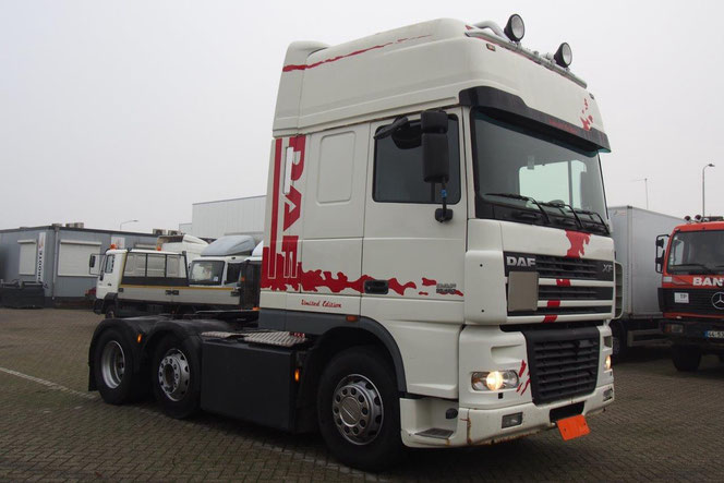
![]()
DAF 95XF 2002 Workshop Manual (1).rar
compressed file archive
15.6 MB
![]()
DAF 95 XF series PDF service manual (1).
Adobe Acrobat Document
16.2 MB
![]()
DAF 95XF Maintenance manual.pdf
Adobe Acrobat Document
3.1 MB
![]()
Electrics DAF XF CF Euro 4, 5 Wiring Dia
compressed file archive
7.6 MB
![]()
DAF 95XF xe engine manual pdf.pdf
Adobe Acrobat Document
3.6 MB
![]()
DAF 95XF Series Electrical Wiring Diagra
Adobe Acrobat Document
6.4 MB
Trucks of this series are available in two-, three- and four-axle versions with 381-530 hp engines. are designed for the most intensive transport work and long-distance transportations with an
annual mileage of up to 150-200 thousand km.
These most powerful trucks in the DAF family have not undergone significant changes in recent years. However, at the end of 1999, two new items appeared here. The first was the new 12.6-liter
XE390C engine of our own production, which replaced the 14-liter Cummins diesel engine of the same power. The new unit is lightweight (only 1050 kg), stands out for its high liter capacity,
complies with Euro 3 standards and develops 530 hp. at 1900 rpm.
All models featuring the particularly comfortable Super Space Cab are fitted as standard with the new Servoshift transmission system. This device, using a pneumatic cylinder built into the drive,
reduces the force applied by the driver to change gear by 50%. On other models in the 95XF series, Servoshift is available on request. The total mass of road trains towed by tractors of this
series reaches 60 tons.
SPECIFICATIONS
Total information
Curb weight, kg 7760
Fifth wheel load, kg 12000
Full mass of the road train, kg 44000
Maximum speed (with a limiter), km / h 85
Diesel engine with turbocharging and intercooler
Power, kW / h.p. 315 at 1900 rpm
Maximum torque, Nm 1950 at 1000-1500 rpm
Working volume, l 12.6
Transmission clutch — single plate with diaphragms. spring, hydraulic drive and pneumatic booster
Transmission mechanical 16-speed with divider and range
The main gear is single, hypoid, with a differential lock
Gear ratio 3.31
Chassis
Suspension front dependent, leaf spring, with stabilizer bar
Rear dependent suspension, on four air bellows, with stabilizer
Drum brakes with a separate pneumatic drive and ABS, with power accumulators of the rear mechanisms
Power steering
Tire size 295 / 80R22.5
What is the difference between the 95XF and the XF95?
They can be freely distinguished, even simply by their appearance. The first version has the full designation 95XF on the right side of the cockpit, while the second has only the letter index XF
left, and it is already on the left. The radiator grill of the first version was completely straight, while in the newer one it is slightly beveled towards the bottom. The side deflectors of the
older car had an elongated shape, while in the successor they became shortened, but due to the optimal aerodynamic shape, they were more effective — not only the door handles, but also the side
windows were not contaminated. Changes have taken place in the headlights: they have become narrower. An additional opening was made in the plastic lining of the headlight to improve the airflow
of the lower stage.
Engine DAF XF 95 430
The truck is equipped with a diesel engine manufactured by the American company Paccar (which has been the owner of DAF since the late 90s) — Paccar-95.43O. This power unit is equipped with the
UPEC injection system, which has injectors with electronically controlled pumps, which increases the environmental friendliness and efficiency of the power plant. The diesel engine of the DAF XF
95 43O meets the Euro-Z environmental standards.
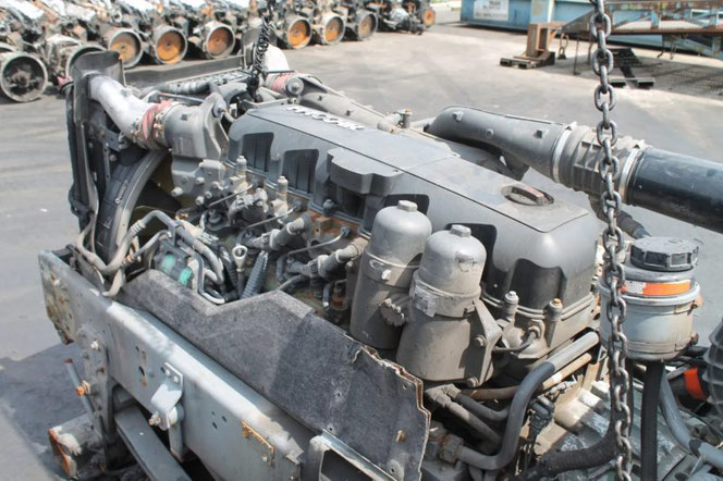
It is a four-stroke, six-cylinder, in-line, liquid-cooled, turbocharged, 12-valve diesel engine. Its working volume is 116OO cubic centimeters (11.6 liters). Compression ratio: 14.5: 1. Cylinder
diameter: 13O mm. Piston stroke: 146 mm. Rotation frequency — 2300 rpm. Maximum torque — 19OO N.m The first versions of the XF 95 series were equipped with liquid preheaters, and later variations
were equipped with autonomous heaters with a fuel tank heating function. Truck oil change period is 9OOOO km.
Transmission DAF XF 95 430
As already mentioned, the basic version of the DAF XF 95 43O is equipped with a 16-speed ZF Servoshift manual gearbox. And as an option, these trucks were equipped with 16 and 12-speed automatic
transmissions ZF AS Tronic (gear ratio — 3.31). Versions with automatic transmission are, of course, much more expensive, but they have their own undoubted advantages. On long journeys, the
driver’s concentration begins to decrease, and the time it takes to select the correct gear increases. And this leads to increased or greatly reduced revs, to wrong gear selections.
The DAF XF 95 43O is equipped with a diaphragm spring single plate clutch, which is hydraulically actuated with an air booster. The main gear is hypoid, single, with a differential lock function.
The DAF XF 95 clutch does not relate well to a partially depressed pedal, to overload and does not like frequent inclusions during slipping. The service life of this element can be significantly
reduced with frequent such exploitation.
Suspension, chassis, brakes
The front suspension on the DAF XF 95 43O truck is of spring type, with an anti-roll bar. At the rear, pneumatics are installed, with a stabilizer bar, which is also supplemented by the ECAS
system. It controls the suspension elements. When drum brakes in a tractor were replaced by more modern ventilated disc counterparts, this significantly increased the efficiency of the braking
system. Old modifications of DAF 95 were equipped with drum brakes with hydraulic accumulators of the rear mechanisms, ABS system and a separate pneumatic drive. The latest models have also
received an EBS system with increased efficiency. The brakes apply to the wheels of the front and rear axles. The resource of their work is approximately 45OOO km. The chassis of all DAF XF95s is
simple and reliable. With proper care and timely maintenance on a new car, the first 6OO-65O thousand km with it are absolutely no hassle. On used cars, you cannot name specific terms of service:
after all, it is not known how correct the speedometer readings are, how and how the car was operated. DAF XF95 vehicles were equipped with 295 /  R22.5 tires.