-
Contents
-
Table of Contents
-
Troubleshooting
-
Bookmarks
Quick Links
x930 Series
Gigabit Layer 3 Ethernet Switches
AT-x930-28GTX
AT-x930-28GPX
AT-x930-28GSTX
AT-x930-52GTX
AT-x930-52GPX
Installation Guide for Stand-alone
Switches
613-002100 Rev. A
Related Manuals for Allied Telesis AT-x930-28GTX
Summary of Contents for Allied Telesis AT-x930-28GTX
-
Page 1
Series Gigabit Layer 3 Ethernet Switches AT-x930-28GTX AT-x930-28GPX AT-x930-28GSTX AT-x930-52GTX AT-x930-52GPX Installation Guide for Stand-alone Switches 613-002100 Rev. A… -
Page 2
Allied Telesis, Inc. has been advised of, known, or should have known, the… -
Page 3
Electrical Safety and Emissions Standards This product meets the following standards. U.S. Federal Communications Commission Radiated Energy Note: This equipment has been tested and found to comply with the limits for a Class A digital device pursuant to Part 15 of FCC Rules. -
Page 4
Translated Safety Statements Important: Safety statements that have the symbol are translated into multiple languages in the Translated Safety Statements document at www.alliedtelesis.com/support. -
Page 5: Table Of Contents
Contents Preface ………………………………11 Document Conventions ………………………….12 Contacting Allied Telesis …………………………13 Chapter 1: Overview ………………………….. 15 Models ………………………………16 Features ………………………………17 x930 Models ……………………………17 10/100/1000 Mbps Twisted Pair Ports …………………….17 Power Over Ethernet …………………………17 SFP Slots …………………………….17 SFP+ Slots ……………………………..18 S1 and S2 Stacking Slots ………………………..19 LEDs……………………………….19…
-
Page 6
Contents USB Port ………………………………. 51 Console Port …………………………….52 Chapter 2: Beginning the Installation ……………………..53 Reviewing Safety Precautions ……………………….54 Choosing a Site for the Switch……………………….59 Unpacking the Switch …………………………… 60 Chapter 3: Installing the Power Supplies ……………………63 Installing the Power Supplies………………………… -
Page 7
Figure 7: AT-PWR800 Power Supply ………………………26 Figure 8: AT-PWR1200 Power Supply ……………………..27 Figure 9: LEDs for the 10/100/1000Base-T Ports on the AT-x930-28GTX AT-x930-52GTX Switches……..43 Figure 10: LEDs for the 10/100/1000Base-T Ports on the AT-x930-28GPX and AT-x930-52GPX Switches ……45 Figure 11: SFP Slot LEDs …………………………46 Figure 12: SFP+ Slot LEDs …………………………47… -
Page 8
Figures Figure 50: Switch Initialization Messages (Continued) …………………..110 Figure 51: Connecting the Management Cable to the Console Port ………………113 Figure 52: User Exec Mode Prompt……………………….115 Figure 53: SHOW STACK Command ……………………..115 Figure 54: Moving to the Global Configuration Mode ………………….116 Figure 55: Confirmation Prompt for the NO STACK ENABLE Command …………….116 Figure 56: Disabling VCStack. -
Page 9
Table 8: Power Budgets of the AT-PWR1200 Power Supply ………………..35 Table 9: NET MGMT Port LED ……………………….41 Table 10: LEDs on the 10/100/1000Base-T Ports on the AT-x930-28GTX and AT-x930-52GTX Switches …….44 Table 11: LEDs on the 10/100/1000Base-T Ports on the AT-x930-28GPX and AT-x930-52GPX Switches …….45 Table 12: SFP Slot LEDs on the AT-x930-28GSTX Switch ………………..47… -
Page 10
Tables… -
Page 11: Preface
Layer 3, Gigabit Ethernet switches. This preface contains the following sections: “Document Conventions” on page 12 “Contacting Allied Telesis” on page 13 Note This guide explains how to install the switches as stand-alone units. For instructions on how to build a stack with Virtual Chassis Stacking ™…
-
Page 12: Document Conventions
Preface Document Conventions This document uses the following conventions: Note Notes provide additional information. Caution Cautions inform you that performing or omitting a specific action may result in equipment damage or loss of data. Warning Warnings inform you that performing or omitting a specific action may result in bodily injury.
-
Page 13: Contacting Allied Telesis
Series Installation Guide for Stand-alone Switches Contacting Allied Telesis If you need assistance with this product, you may contact Allied Telesis technical support by going to the Support & Services section of the Allied Telesis web site at www.alliedtelesis.com/support. You can find links for the following services on this page: …
-
Page 14
Preface… -
Page 15: Chapter 1: Overview
Chapter 1 Overview This chapter contains the following sections: “Models” on page 16 “Features” on page 17 “Front and Back Panels” on page 21 “Management Panel” on page 24 “Power Supplies” on page 25 “10/100/1000Base-T Twisted Pair Ports”…
-
Page 16: Models
10/100/1000 Model Base-T SFP Slots SFP+ Slots PoE+ VCStack Ports AT-x930-28GTX AT-x930-28GPX AT-x930-28GSTX AT-x930-52GTX AT-x930-52GPX Additional information is listed here: The switches do not come with power supplies. The power supplies must be ordered separately. For more information, refer to “Power Supplies”…
-
Page 17: Features
Series Installation Guide for Stand-alone Switches Features Here are the switches and their features: x930 Models Here are the switches in the x930 Series: AT-x930-28GTX AT-x930-28GPX AT-x930-28GSTX AT-x930-52GTX AT-x930-52GPX 10/100/1000 Here are the basic features of the 10/100/1000 Mbps twisted pair ports: Mbps Twisted …
-
Page 18: Sfp+ Slots
The SFP+ slots do not support 100Mbps 100Base-FX transceivers. Note The slots support full-duplex mode only.They do not support half- duplex mode. Note SFP and SFP+ transceivers must be purchased separately. For a list of supported transceivers, contact your Allied Telesis distributor or reseller.
-
Page 19: S1 And S2 Stacking Slots
x930 Series Installation Guide for Stand-alone Switches Note SFP+ slots 27/S1 and 28/S2 on the 28-port switches and slots 51/S1 and 52/S2 on the 52-port switches are initially configured as stacking slots for the VCStack feature. If you plan to use the switch as a stand-alone unit, you may disable the VCStack feature and use the slots with standard SFP or SFP+ transceivers.
-
Page 20: Management Methods
Chapter 1: Overview Management Here are the methods for managing the switches: Methods Local management through the Console port Remote Telnet and Secure Shell management Remote HTTP and HTTPS web browser management SNMPv1, v2c, and v3 Power Supplies Here are the power supplies: …
-
Page 21: Front And Back Panels
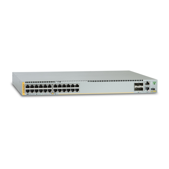
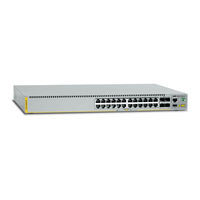
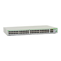
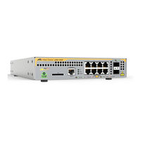
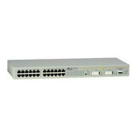
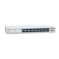
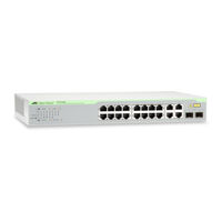
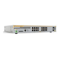
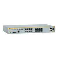
The front panels of the x930 Series switches are shown in Figure 1 and Figure 2 on page 22. AT-x930-28GTX Management 10/100/1000Base-T Ports Panel SFP+ Slots SFP+ or Stacking Slots AT-x930-28GPX Management 10/100/1000Base-T Ports Panel with PoE+ SFP+ Slots SFP+ or Stacking Slots Figure 1. Front Panels of the AT-x930-28GTX and AT-x930-28GPX Switches…
-
Page 22: Figure 2: Front Panels Of The At-X930-28Gstx, At-X930-52Gtx, And At-X930-52Gpx Switches
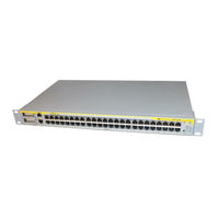
Chapter 1: Overview AT-x930-28GSTX 10/100/1000Base-T Ports SFP Slots Management Panel SFP+ Slots SFP+ or Stacking Slots AT-x930-52GTX 10/100/1000Base-T Ports Management Panel SFP+ Slots SFP+ or Stacking Slots AT-x930-52GPX 10/100/1000Base-T Ports Management with PoE+ Panel SFP+ Slots SFP+ or Stacking Slots Figure 2.
-
Page 23: Figure 3: Back Panel
x930 Series Installation Guide for Stand-alone Switches Figure 3 shows the back panel. The back panel is the same on all of the switches. AT-FAN09ADP Power Supply Slot B AT-FAN09 Power Supply Slot A Module Fan Module with AT-PNL250 Blank Panel Figure 3.
-
Page 24: Management Panel
Chapter 1: Overview Management Panel Figure 4 identifies the components in the management panel on the x930 Series switches. Console Management Port Switch ID LED eco-friendly Button USB Port Network Management Port Figure 4. Management Panel…
-
Page 25: Power Supplies
AT-PWR1200 The power supplies can work in any of the switches, but two models are primarily intended for the non-PoE AT-x930-28GTX and AT-x930-52GTX Switches and two for the PoE AT-x930-28GPX and AT-x930-52GPX Switches. The AT-PWR250 Power Supply, shown in Figure 5, is primarily designed for the non-PoE switches and has these operating characteristics: …
-
Page 26: Figure 6: At-Pwr250-80 Power Supply
Chapter 1: Overview Figure 6. AT-PWR250-80 Power Supply Figure 7 illustrates the AT-PWR800 Power Supply.This power supply is primarily intended for the PoE AT-x930-28GPX and AT-x930-52GPX Switches. It provides both system power to the switch as well as up to 480 watts of PoE power for the powered devices connected to the network ports.
-
Page 27: Guidelines
You may not install two different power supply models in the switch. The non-PoE AT-x930-28GTX and AT-x930-52GTX Switches require only one power supply for full operations. Installing a second power supply adds power redundancy by protecting against interruptions to network operations in the event one power supply loses power or fails.
-
Page 28
Chapter 1: Overview amount of power for PoE or adds PoE redundancy. For further information, refer to “Power Budget” on page 33. The DC wires for the AT-PWR250-80 DC Power Supply should be routed from a DC load center containing appropriate overcurrent branch protection for each DC feed, as required by the cognizant local electrical authority. -
Page 29: 10/100/1000Base-T Twisted Pair Ports
x930 Series Installation Guide for Stand-alone Switches 10/100/1000Base-T Twisted Pair Ports The twisted pair ports on the switches are described in this section. Speed The ports can operate at 10, 100, or 1000 Mbps. The speeds may be set manually using the management software or automatically with Auto- Negotiation (IEEE 802.3u), the default setting.
-
Page 30: Maximum Distance
Chapter 1: Overview The MDI and MDI-X settings do not apply when ports are operating at 1000 Mbps. Maximum The ports have a maximum operating distance of 100 meters (328 feet). Distance Cable The cable requirements of the ports are given in Table 2. Requirements Table 2.
-
Page 31: Power Over Ethernet
x930 Series Installation Guide for Stand-alone Switches Power Over Ethernet The AT-x930-28GPX and AT-x930-52GPX Switches feature Power over Ethernet (PoE) on the 10/100/1000Base-T ports. PoE is used to supply power to network devices over the same twisted pair cables that carry the network traffic.
-
Page 32: Cable Requirements
Chapter 1: Overview Table 3. IEEE Powered Device Classes Maximum Power Class Output from a Switch PD Power Range Port 15.4W 0.44W to 12.95W 4.0W 0.44W to 3.84W 7.0W 3.84W to 6.49W 15.4W 6.49W to 12.95W 30.0W 12.95W to 25.5W Cable The cable requirements for ports operating at 10 or 100Mbps are given in Table 4.
-
Page 33: Power Budget
x930 Series Installation Guide for Stand-alone Switches The cable requirements for ports operating at 1000Mbps are given in Table 5. Table 5. Twisted Pair Cable Requirements for the 10/100/1000Base-T Ports at 1000Mbps 1000Mbps Cable Type Non- PoE+ Standard TIA/EIA 568-B-compliant Category 3 shielded or unshielded cabling with 100 ohm impedance and a frequency of 16 MHz.
-
Page 34: Table 7: Power Budgets Of The At-Pwr800 Power Supply
Chapter 1: Overview Note The AT-PWR250 and AT-PWR250-80 Power Supplies are intended for the non-PoE AT-x930-28GTX and AT-x930-52GTX Switches. They are not intended for the AT-x930-28GPX and AT-x930-52GPX Switches because they do not provide power for PoE + devices. You may install them in the PoE+ switches, but the switches will not support PoE devices.
-
Page 35: Port Prioritization
x930 Series Installation Guide for Stand-alone Switches Table 8 lists the power budgets for the switch with one or two AT- PWR1200 Power Supplies and the power boost mode. Table 8. Power Budgets of the AT-PWR1200 Power Supply Number of Power State of Power Power Budget…
-
Page 36: Wiring Implementation
Chapter 1: Overview Ports set to the Critical level, the highest priority level, are guaranteed power before any of the ports assigned to the other two priority levels. Ports assigned to the other priority levels receive power only if all the Critical ports are receiving power.
-
Page 37
x930 Series Installation Guide for Stand-alone Switches IEEE 802.3af standard. Powered devices that comply with the IEEE 802.3af standard are required to support both power delivery methods. Legacy devices that do not comply with the standard will work with the switch if they are powered on pins 1, 2, 3, and 6. -
Page 38: Sfp Slots
Chapter 1: Overview SFP Slots The twenty four SFP slots on the AT-x930-28GSTX Switch support the following types of transceivers: 100Base-FX, 1000Base-T, and 1000Base-SX/LX SFP transceivers Single-port BiDi 100Base-FX and 1000Base-LX SFP transceivers 1000Base-ZX SFP transceivers The slots are paired with the twenty four 10/100/1000Base-T twisted pair ports.
-
Page 39: Sfp+ Slots
The switches support a variety of short and long distance SFP and SFP+ modules. For a list of supported SFP modules, contact your Allied Telesis representative or visit our web site. Note The SFP+ slots do not support 100Mbps 100Base-FX transceivers.
-
Page 40: Stacking S1 And S2 Sfp+ Slots
Chapter 1: Overview Stacking S1 and S2 SFP+ Slots The four SFP+ slots on the front panel of the switch are used with SFP 1000Mbps or SFP+ 10Gbps transceivers to add high speed links to the switch. However, SFP+ slots 27/S1 and 28/S2 on the 28-port switches and slots 51/S1 and 52/S2 on the 52-port switches have an additional function.
-
Page 41: Ethernet Management Port (Net Mgmt)
x930 Series Installation Guide for Stand-alone Switches Ethernet Management Port (NET MGMT) The NET MGMT port in the management panel of the switch is a separate routed eth0 interface. The interface is not part of the switching matrix of the Ethernet line cards, but the CPU on the controller card can route traffic in or out of the port from the line cards.
-
Page 42: Eco-Friendly Button
Chapter 1: Overview eco-friendly Button The eco-friendly button on the front panel of the switch is used to toggle the port LEDs on or off. You might turn off the LEDs to conserve electricity when you are not monitoring the device. You can also toggle the LEDs with the ECOFRIENDLY LED and NO ECOFRIENDLY LED commands in the Global Configuration mode of the command line interface.
-
Page 43: Leds
Switches have two LEDs that display link, activity and duplex mode Twisted Pair information. The LEDs are shown in Figure 9. Ports Link/Activity Duplex Mode Duplex Mode Link/Activity Figure 9. LEDs for the 10/100/1000Base-T Ports on the AT-x930-28GTX AT-x930-52GTX Switches The LEDs are described in Table 10 on page 44.
-
Page 44: Table 10: Leds On The 10/100/1000Base-T Ports On The At-X930-28Gtx And At-X930-52Gtx Switches
Chapter 1: Overview Table 10. LEDs on the 10/100/1000Base-T Ports on the AT-x930-28GTX and AT-x930-52GTX Switches State Description Solid Green A port has established a 1000 Mbps link to a network device. Flashing A port is transmitting or receiving data at…
-
Page 45: Figure 10: Leds For The 10/100/1000Base-T Ports On The At-X930-28Gpx And At-X930-52Gpx Switches
x930 Series Installation Guide for Stand-alone Switches Link/Activity Link/Activity Figure 10. LEDs for the 10/100/1000Base-T Ports on the AT-x930-28GPX and AT-x930-52GPX Switches The LEDs are described in Table 11. Table 11. LEDs on the 10/100/1000Base-T Ports on the AT-x930-28GPX and AT-x930-52GPX Switches State Description Solid Green…
-
Page 46: Leds For The Sfp Slots
Chapter 1: Overview Table 11. LEDs on the 10/100/1000Base-T Ports on the AT-x930-28GPX and AT-x930-52GPX Switches (Continued) State Description Green The switch detects a powered device (PD) on the port and is delivering power to it. Solid Amber The switch has shut down PoE+ on the port because of a fault condition.
-
Page 47: Leds For The Sfp+ Slots
x930 Series Installation Guide for Stand-alone Switches The possible states of the LED for the SFP slots are described in Table 12. Table 12. SFP Slot LEDs on the AT-x930-28GSTX Switch State Description Solid green The SFP transceiver in the slot has established a link at 1000 Mbps to a network device.
-
Page 48: Leds For The Stacking Slots
Chapter 1: Overview Table 13. SFP+ Slot LEDs State Description Solid green The SFP+ transceiver in the slot has established a link at 10 Gbps to a network device. Flashing The SFP+ transceiver is receiving or green transmitting packets to a network device at 10 Gbps.
-
Page 49: Switch Id Led
x930 Series Installation Guide for Stand-alone Switches Switch ID LED The Switch ID LED, shown in Figure 13 on page 49, displays the ID number of the switch. A stand-alone switch has the ID number 0. Switches in a VCStack have the numbers 1 to 8. Chapter 8, “Powering On the Switch”…
-
Page 50: Figure 15: Switch Id Leds In The Low Power Mode
Chapter 1: Overview The internal temperature of the switch has exceeded the normal operating range and the switch may shut down. Note You can use the SHOW SYSTEM ENVIRONMENT command in the command line interface to identify the source of the problem. The states of the LED when the switch is operating in the low power mode are shown in Figure 15.
-
Page 51: Usb Port
x930 Series Installation Guide for Stand-alone Switches USB Port The management panel has a USB port. You may use the port to store configuration files on flash drives or to restore configuration files to switches whose settings have been lost or corrupted, or to quickly configure replacement units.
-
Page 52: Console Port
Chapter 1: Overview Console Port The Console port is used to establish a management session with the switch to configure its features and parameter settings. This type of management uses serial RS-232 and is commonly referred to as local or out-of-band management because it is not conducted over your network.
-
Page 53: Chapter 2: Beginning The Installation
Chapter 2 Beginning the Installation The chapter contains the following sections: “Reviewing Safety Precautions” on page 54 “Choosing a Site for the Switch” on page 59 “Unpacking the Switch” on page 60…
-
Page 54: Reviewing Safety Precautions
Chapter 2: Beginning the Installation Reviewing Safety Precautions Please review the following safety precautions before beginning the installation procedure. Note Safety statements that have the symbol are translated into multiple languages in the Translated Safety Statements document at www.alliedtelesis.com/support. Warning Class 1 Laser product.
-
Page 55
x930 Series Installation Guide for Stand-alone Switches Warning Power cord is used as a disconnection device. To de-energize equipment, disconnect the power cord. E3 Warning Class I Equipment. This equipment must be earthed. The power plug must be connected to a properly wired earth ground socket outlet. -
Page 56
E25 Warning The chassis may be heavy and awkward to lift. Allied Telesis recommends that you get assistance when mounting the chassis in an equipment rack. E28 Note Use dedicated power circuits or power conditioners to supply reliable electrical power to the device. -
Page 57
x930 Series Installation Guide for Stand-alone Switches Note If installed in a closed or multi-unit rack assembly, the operating ambient temperature of the rack environment may be greater than the room ambient temperature. Therefore, consideration should be given to installing the equipment in an environment compatible with the manufacturer’s maximum rated ambient temperature (Tmra). -
Page 58
Chapter 2: Beginning the Installation Caution The unit does not contain serviceable components. Please return damaged units for servicing. E42 Warning The temperature of an operational SFP or SFP+ transceiver may exceed 70° C (158° F). Exercise caution when removing or handling a transceiver with unprotected hands. -
Page 59: Choosing A Site For The Switch
x930 Series Installation Guide for Stand-alone Switches Choosing a Site for the Switch Observe these requirements when planning the installation of the switch. If you plan to install the switch in an equipment rack, check to be sure that the rack is safely secured so that it will not tip over. Devices in a rack should be installed starting at the bottom, with the heavier devices near the bottom of the rack.
-
Page 60: Unpacking The Switch
Chapter 2: Beginning the Installation Unpacking the Switch Figure 16 lists the items in the accessory kit that comes with the switch. If any item is missing or damaged, contact your Allied Telesis sales representative for assistance. One 2 m (6.6 ft) local management cable with RJ-45 (8P8C) and DB-9 (D- sub 9-pin) connectors.
-
Page 61: Figure 17: Pre-Installed Items
Figure 17. Pre-installed Items Note You should retain the original packaging material in the event you need to return the unit to Allied Telesis. Note The product does not come with power supplies. Power supplies must be ordered separately.
-
Page 62
Chapter 2: Beginning the Installation… -
Page 63: Chapter 3: Installing The Power Supplies
Chapter 3 Installing the Power Supplies The sections in this chapter are listed here: “Installing the Power Supplies” on page 64 “Installing a Blank Power Supply Slot Cover” on page 70…
-
Page 64: Installing The Power Supplies
Chapter 3: Installing the Power Supplies Installing the Power Supplies This section contains the procedure for installing the power supplies in the switch. If you are planning to install the switch in an equipment rack, you may install the power supplies either before or after installing the device in the rack.
-
Page 65: Figure 18: Removing The At-Pnl250 Blank Panel
x930 Series Installation Guide for Stand-alone Switches Figure 18. Removing the AT-PNL250 Blank Panel 3. Unpack the power supply from its shipping container. Caution The power supply is heavy. Use both hands to lift it. You might injure yourself or damage the power supply if you drop it. 4.
-
Page 66: Figure 19: Power Supply Accessory Items
Chapter 3: Installing the Power Supplies Table 15. Accessory Items Included with the Power Supplies One Power Cord Power Supply One Power Cord Retaining Clip AT-PWR250 AT-PWR250-80 AT-PWR800 AT-PWR1200 Power Cord Power Cord Retaining Clip Figure 19. Power Supply Accessory Items Note The power cord that comes with the AT-PWR1200 Power Supply for installations in North America has a 20 Amp, 125 V NEMA 5-20P…
-
Page 67: Figure 20: Installing A Power Supply
x930 Series Installation Guide for Stand-alone Switches Handle Figure 20. Installing a Power Supply Caution Do not use excessive force when seating the module, because this may damage the system or the module. If the module resists seating, remove it from the system, realign it, and try again. E47 Caution The power supply is not hot-swappable.
-
Page 68: Figure 21: Improper Installation Of A Power Supply
Chapter 3: Installing the Power Supplies Figure 21. Improper Installation of a Power Supply 6. Secure the power supply to the switch by tightening the two captive screws with a cross-head screwdriver. Refer to Figure 22. Figure 22. Tightening the Captive Screws on the Power Supply…
-
Page 69: Figure 23: Installing The Power Cord Retaining Clip
x930 Series Installation Guide for Stand-alone Switches 7. If you installed the AT-PWR250 or AT-PWR800 Power Supply, install the power cord retaining clip on the AC plug. Press the sides of the clip inward and insert the two ends into the holes on the AC socket. Refer to Figure 23.
-
Page 70: Installing A Blank Power Supply Slot Cover
Chapter 3: Installing the Power Supplies Installing a Blank Power Supply Slot Cover If you installed only one power supply in the switch, perform this procedure to install a blank panel over the empty power supply slot: 1. Position the appropriate blank panel over the empty power supply slot. Use the AT-PNL800/1200 Blank Panel included in the accessory kit if the switch has only one AT-PWR800 or AT-PWR1200 Power Supply.
-
Page 71: Figure 25: Tightening The Captive Screws On The Power Supply Blank Panel
x930 Series Installation Guide for Stand-alone Switches Figure 25. Tightening the Captive Screws on the Power Supply Blank Panel 3. Do one of the following: To install the switch on a table, go to Chapter 4, “Installing the Switch on a Table” on page 73. …
-
Page 72
Chapter 3: Installing the Power Supplies… -
Page 73: Chapter 4: Installing The Switch On A Table
Chapter 4 Installing the Switch on a Table To install the switch on a table, perform the following procedure: Warning Do not stack switches on a table because that could create a personal safety hazard if you need to move or replace units. 1.
-
Page 74
Chapter 4: Installing the Switch on a Table 6. Turn the chassis over. 7. Do one of the following: If you have not installed the power supplies, go to Chapter 3, “Installing the Power Supplies” on page 63. If the switch contains the AT-PWR250-80 DC Power Supply, go to Chapter 7, “Wiring the DC Connector on the AT-PWR250-80 Power Supply”… -
Page 75: Chapter 5: Installing The Switch In An Equipment Rack
Chapter 5 Installing the Switch in an Equipment Rack This chapter contains the instructions for installing the switch in an equipment rack. The procedures in this chapter are listed here: “Required Items” on page 76 “Installing the Switch in an Equipment Rack” on page 77…
-
Page 76: Required Items
Chapter 5: Installing the Switch in an Equipment Rack Required Items This procedure requires the following items: Two equipment rack brackets (included with the switch) Eight bracket screws (included with the switch) Cross-head screwdriver (not provided) Four standard equipment rack screws (not provided) Note The switch comes with four equipment rack brackets and sixteen…
-
Page 77: Installing The Switch In An Equipment Rack
59. Here is the procedure for installing the switch in a 19-inch equipment rack. Caution The chassis may be heavy and awkward to lift. Allied Telesis recommends that you get assistance when mounting the chassis in an equipment rack. E28…
-
Page 78: Figure 27: Attaching The Equipment Rack Brackets
Chapter 5: Installing the Switch in an Equipment Rack Figure 27. Attaching the Equipment Rack Brackets…
-
Page 79: Figure 28: Attaching The Equipment Rack Brackets (Continued)
x930 Series Installation Guide for Stand-alone Switches Figure 28. Attaching the Equipment Rack Brackets (Continued) 3. Have two people hold the switch in the equipment rack while you secure it using standard equipment rack screws (not provided), as shown in Figure 29 on page 80.
-
Page 80: Figure 29: Installing The Switch In An Equipment Rack
Chapter 5: Installing the Switch in an Equipment Rack Figure 29. Installing the Switch in an Equipment Rack 4. Do one of the following: If you have not installed the power supplies, go to Chapter 3, “Installing the Power Supplies” on page 63. …
-
Page 81: Chapter 6: Installing The Switch On A Wall
Chapter 6 Installing the Switch on a Wall The procedures in this chapter are listed here: “Switch Orientation on the Wall” on page 82 “Recommended Minimum Wall Area Dimensions” on page 83 “Plywood Base for a Wall with Wooden Studs” on page 85 …
-
Page 82: Switch Orientation On The Wall
Chapter 6: Installing the Switch on a Wall Switch Orientation on the Wall You may install the switch on a wall with the front panel on the left or right, as shown in Figure 30. You may not install it with the front panel on the top or bottom.
-
Page 83: Recommended Minimum Wall Area Dimensions
x930 Series Installation Guide for Stand-alone Switches Recommended Minimum Wall Area Dimensions The recommended minimum dimensions for the reserved wall area for the switch are listed here: Width: 68.0 centimeters (27 inches) Height: 58.4 centimeters (23 inches) You should position the switch in the reserved wall area such that the front panel has more space than the rear panel.
-
Page 84: Figure 32: Minimum Wall Area Dimensions With The Front Panel On The Right
Chapter 6: Installing the Switch on a Wall Figure 32. Minimum Wall Area Dimensions with the Front Panel on the Right…
-
Page 85: Plywood Base For A Wall With Wooden Studs
x930 Series Installation Guide for Stand-alone Switches Plywood Base for a Wall with Wooden Studs If you are installing the switch on a wall that has wooden studs, Allied Telesis recommends using a plywood base to attach the device to the wall.
-
Page 86: Figure 34: Steps To Installing The Switch With A Plywood Base
Chapter 6: Installing the Switch on a Wall The plywood base allows you to mount the switch on two wall studs. If you install the switch without the base, only one side of it would be attached to a stud. This is because the standard distance between two studs in a wall is 41 centimeters (16 inches) while the distance between the left and right brackets on the switch is 36.2 centimeters (14 1/4 inches).
-
Page 87: Installation Guidelines
x930 Series Installation Guide for Stand-alone Switches Installation Guidelines Here are the guidelines to installing the switch on a wall: You may install the switch on a wall that has wooden studs. You may install it on a concrete wall. …
-
Page 88
Chapter 6: Installing the Switch on a Wall Four screws and anchors for attaching the plywood base to the wall (not provided) Caution The supplied screws and anchors may not be appropriate for all walls. A qualified building contractor should determine the hardware requirements for your wall prior to installing the switch. -
Page 89: Installing The Plywood Base
x930 Series Installation Guide for Stand-alone Switches Installing the Plywood Base A plywood base is recommended when installing the switch on a wall that has wooden studs. Refer to “Plywood Base for a Wall with Wooden Studs” on page 85. Consult a qualified building contractor for installation instructions for the plywood base.
-
Page 90: Installing The Switch On The Plywood Base
This procedure assumes that the plywood base for the switch is already installed on the wall. Please review “Reviewing Safety Precautions” on page 54 and “Choosing a Site for the Switch” on page 59 before performing this procedure. Allied Telesis recommends a minimum of three people for this procedure. Warning The device is heavy.
-
Page 91: Figure 36: Mounting Holes
x930 Series Installation Guide for Stand-alone Switches RKMT-SL01 Rack Mounting Kit. For this procedure, you need to use the holes for the brackets. The holes are identified in Figure 36. Wall Bracket Wall Bracket Holes Holes Front (Left Side) Wall Bracket Wall Bracket Holes Holes…
-
Page 92: Figure 37: Securing The Switch To The Plywood Base
Chapter 6: Installing the Switch on a Wall Figure 37. Securing the Switch to the Plywood Base 4. Do one of the following: If the switch contains the AT-PWR250-80 DC Power Supply, go to Chapter 7, “Wiring the DC Connector on the AT-PWR250-80 Power Supply”…
-
Page 93: Installing The Switch On A Concrete Wall
Series Installation Guide for Stand-alone Switches Installing the Switch on a Concrete Wall Allied Telesis recommends a minimum of three people for this procedure. To install the switch on a concrete wall, perform the following procedure: Warning The device is heavy. Always ask for assistance before moving or lifting it to avoid injuring yourself or damaging the equipment.
-
Page 94: Figure 38: Marking The Locations Of The Bracket Holes On A Concrete Wall
3. Please review the following guidelines: Prior to drilling, set the drill to hammer and rotation mode. The modes break up the concrete and clean out the hole. Allied Telesis recommends cleaning out the holes with a brush or compressed air.
-
Page 95: Figure 39: Installing The Switch On A Concrete Wall
x930 Series Installation Guide for Stand-alone Switches 6. Insert the four anchors into the holes. 7. Have two people hold the switch at the selected wall location while you secure it to the wall with the four provided screws. Refer to Figure 39. Figure 39.
-
Page 96
Chapter 6: Installing the Switch on a Wall… -
Page 97: Chapter 7: Wiring The Dc Connector On The At-Pwr250-80 Power Supply
Chapter 7 Wiring the DC Connector on the AT- PWR250-80 Power Supply This chapter contains the procedure for wiring the DC connector on the AT-PWR250-80 DC power supply. Warning As a safety precaution, install a circuit breaker with a minimum value of 15 Amps between the equipment and the DC power source.
-
Page 98: Figure 40: On/Off Switch On At-Pwr250-80 Power Supply
Chapter 7: Wiring the DC Connector on the AT-PWR250-80 Power Supply 2. Verify that the On/Off switch on the power supply is in the Off position. Refer to Figure 40. On/Off Switch Figure 40. On/Off Switch on AT-PWR250-80 Power Supply 3.
-
Page 99: Figure 42: Stripped Wire
x930 Series Installation Guide for Stand-alone Switches Warning Do not strip more than the recommended amount of wire. Stripping more than the recommended amount can create a safety hazard by leaving exposed wire on the terminal block after installation. E10 8mm +/- 1mm (0.31 in.
-
Page 100
Chapter 7: Wiring the DC Connector on the AT-PWR250-80 Power Supply 6. Connect the +48 VDC (RTN) feed wire to the terminal block marked + (plus). 7. Connect the -48 VDC feed wire to the terminal block marked — (minus). Warning Check to see if there are any exposed copper strands coming from the installed wires. -
Page 101: Chapter 8: Powering On The Switch
Chapter 8 Powering On the Switch This chapter contains the following procedures: “Powering On AC Power Supplies” on page 102 “Powering On the AT-PWR250-80 DC Power Supply” on page 106 “Monitoring the Initialization Processes” on page 108…
-
Page 102: Powering On Ac Power Supplies
Chapter 8: Powering On the Switch Powering On AC Power Supplies This section contains the procedure for powering on the AT-PWR250, AT-PWR800, or AT-PWR1200 Power Supply. Please review the following items before you power on the device: Connecting the power cords of the switch with two power supplies to different circuits can protect the unit from a power circuit failure.
-
Page 103: Figure 44: Raising The Power Cord Retaining Clip
x930 Series Installation Guide for Stand-alone Switches Figure 44. Raising the Power Cord Retaining Clip 2. Connect the AC power cord to the connector on the power supply and to an appropriate power source. Refer to Figure 45 on page 104.
-
Page 104: Figure 45: Connecting The Ac Power Cord
Chapter 8: Powering On the Switch Figure 45. Connecting the AC Power Cord 3. Lower the power cord retaining clip to secure the cord to the switch. Refer to Figure 46 on page 105.
-
Page 105: Figure 46: Lowering The Power Cord Retaining Clip
x930 Series Installation Guide for Stand-alone Switches Figure 46. Lowering the Power Cord Retaining Clip 4. Examine the DC OUT/FAULT LED on the power supply. The module is operating normally when the LED is green. If the LED is amber or off, refer to Chapter 11, “Troubleshooting”…
-
Page 106: Powering On The At-Pwr250-80 Dc Power Supply
Chapter 8: Powering On the Switch Powering On the AT-PWR250-80 DC Power Supply This section contains the procedure for powering on the AT-PWR250-80 DC Power Supply. Please review the following items before powering on the device: This procedure assumes you have already wired the DC connector on the AT-PWR250-80 DC Power Supply.
-
Page 107
x930 Series Installation Guide for Stand-alone Switches 3. Examine the DC OUT/FAULT LED on the power supply module. The module is operating normally when the LED is green. If the LED is amber or off, refer to Chapter 11, “Troubleshooting” on page 127 for troubleshooting suggestions. -
Page 108: Monitoring The Initialization Processes
_ __/ /| ______ | | ______ | ____ / /______/____ / /____________/ Allied Telesis Inc. AlliedWare Plus (TM) v0.0.0 Current release filename: x930-broadcomdev-20140626-1.rel Original release filename: x930-broadcomdev-20140626-1.rel Built: Thu Jun 26 01:44:29 NZST 2014 Mounting static filesystems…
-
Page 109: Figure 49: Switch Initialization Messages (Continued)
x930 Series Installation Guide for Stand-alone Switches Starting base/poe_done… Starting base/sysctl… Received event poefw.done Starting base/portmapper… Received event syslog.done Starting base/reboot-stability… Checking system reboot stability… Starting base/cron… Starting base/appmond… Starting hardware/openhpi… Starting hardware/timeout… Starting base/inet… Starting base/modules… Received event modules.done Received event board.inserted Received event hardware.done Starting network/startup…
-
Page 110: Figure 50: Switch Initialization Messages (Continued)
Chapter 8: Powering On the Switch Received event network.activated Loading default configuration Warning: flash:/default.cfg does not exist, loading factory defaults. done! Received event network.configured awplus login: Figure 50. Switch Initialization Messages (Continued) After the switch has initialized its management software, go to Chapter 9, “Configuring the Switch for Stand-alone Operation”…
-
Page 111: Chapter 9: Configuring The Switch For Stand-Alone Operation
Chapter 9 Configuring the Switch for Stand-alone Operation This chapter contains the following procedures: “Determining the Status of the Switch” on page 112 “Starting a Local Management Session” on page 113 “Disabling VCStack” on page 115 “Specifying Ports in the Command Line Interface for Stand-alone Switches”…
-
Page 112: Determining The Status Of The Switch
Chapter 9: Configuring the Switch for Stand-alone Operation Determining the Status of the Switch After the switch has initialized its management software, examine the switch ID LED on the front panel and do one of the following: If the LED is displaying “0,” the installation procedure is complete. The switch is now ready for network operations as a stand-alone unit.
-
Page 113: Starting A Local Management Session
x930 Series Installation Guide for Stand-alone Switches Starting a Local Management Session This procedure requires a terminal or a terminal emulator program and the management cable that comes with the switch. To start a local management session on the switch, perform the following procedure: 1.
-
Page 114
Chapter 9: Configuring the Switch for Stand-alone Operation 4. Press Enter. You are prompted for a user name and password. 5. When prompted for a user name, go to “Disabling VCStack” on page 115. -
Page 115: Disabling Vcstack
x930 Series Installation Guide for Stand-alone Switches Disabling VCStack To disable the VCStack feature to use the switch as a stand-alone unit, perform the following procedure: Caution Disabling the VCStack feature requires resetting the switch. Some network traffic may be lost if the device is connected to a live network.
-
Page 116: Figure 54: Moving To The Global Configuration Mode
Chapter 9: Configuring the Switch for Stand-alone Operation 4. Review the following items: If the Operational Status is “Stacking Hardware Disabled,” the VCStack feature is already disabled on the switch and the SFP+ S1 and S2 stacking slots may be used with regular SFP or SFP+ transceivers.
-
Page 117: Figure 56: Disabling Vcstack
x930 Series Installation Guide for Stand-alone Switches awplus(config)#18:04:12 awplus VCS[2119]: Deactivating Stacking Ports on stack member 1. Figure 56. Disabling VCStack. 8. Press the Return key to re-display the Global Configuration mode prompt. 9. Enter the EXIT command to return to the Privileged Exec mode, as shown in Figure 57.
-
Page 118: Specifying Ports In The Command Line Interface For Stand-Alone Switches
Chapter 9: Configuring the Switch for Stand-alone Operation Specifying Ports in the Command Line Interface for Stand-alone Switches The command line interface in the management software on the switch has a parameter for specifying individual ports. The parameter is the PORT parameter and Figure 59 shows its format.
-
Page 119: Chapter 10: Cabling The Networking Ports
Chapter 10 Cabling the Networking Ports This chapter contains the following procedures: “Cabling the Twisted Pair Ports” on page 120 “Guidelines to Handling SFP or SFP+ Transceivers” on page 122 “Installing SFP or SFP+ Transceivers” on page 123…
-
Page 120: Cabling The Twisted Pair Ports
Chapter 10: Cabling the Networking Ports Cabling the Twisted Pair Ports Here are the guidelines to cabling the 10/100/1000Base-T twisted pair ports: The cable specifications for the 10/100/1000Base-T twisted pair ports are listed in Table 2 on page 30. …
-
Page 121
x930 Series Installation Guide for Stand-alone Switches The default duplex mode setting of Auto-Negotiation is not appropriate for ports connected to network devices that do not support Auto-Negotiation and have a fixed duplex mode. You should disable Auto-Negotiation on those ports and set their duplex modes manually to avoid the possibility of duplex mode mismatches. -
Page 122: Guidelines To Handling Sfp Or Sfp+ Transceivers
SFP and SFP+ transceivers are hot-swappable. You may install them while the chassis is powered on. Your Allied Telesis sales representative can provide you with a list of supported transceivers for the units. The operational specifications and fiber optic cable requirements of the transceivers are provided in the documents included with the devices.
-
Page 123: Installing Sfp Or Sfp+ Transceivers
3. If you are installing the transceiver in a top slot, position the transceiver with the Allied Telesis label facing up. If you are installing the transceiver in a bottom slot, position the transceiver with the label facing down.
-
Page 124: Figure 61: Installing An Sfp Transceiver
Chapter 10: Cabling the Networking Ports Figure 61. Installing an SFP Transceiver Note If you are ready to attach the fiber optic cable to the transceiver, continue with the next step. Otherwise, repeat steps 1 to 4 to install the remaining transceivers in the switch. 5.
-
Page 125: Figure 63: Positioning The Sfp Or Sfp+ Handle In The Upright Position
x930 Series Installation Guide for Stand-alone Switches 6. Verify the position of the handle on the transceiver. If the transceiver is in a top slot, the handle should be in the upright position, as shown in Figure 63. If the transceiver is in a bottom slot, the handle should be in the down position.
-
Page 126: Figure 64: Connecting A Fiber Optic Cable To An Sfp Or Sfp+ Transceiver
Chapter 10: Cabling the Networking Ports Figure 64. Connecting a Fiber Optic Cable to an SFP or SFP+ Transceiver 8. Repeat this procedure to install additional transceivers.
-
Page 127: Chapter 11: Troubleshooting
This chapter contains suggestions on how to troubleshoot the switch if a problem occurs. Note For further assistance, please contact Allied Telesis Technical Support at www.alliedtelesis.com/support. Problem 1: The Switch ID LED on the front of the switch is off.
-
Page 128
Chapter 11: Troubleshooting Try connecting another network device to the twisted pair port with a different cable. If the twisted pair port is able to establish a link, then the problem is with the cable or the other network device. … -
Page 129
The internal temperature of the switch has exceeded the normal operating range and the switch may shut down. Contact your Allied Telesis sales representative for assistance. Problem 8: A port on the AT-x930-28GPX or AT-x930-52GPX Switch is not providing power to a PoE device. -
Page 130
Chapter 11: Troubleshooting Solutions: Try the following: Review the PD’s documentation to confirm that the device supports Mode A of the IEEE 802.3at standard. Mode A is one of two modes that define the connector pins that deliver the power from the port in the switch to the powered device. -
Page 131: Appendix A: Technical Specifications
Appendix A Technical Specifications This appendix contains the following sections: ”Physical Specifications” on page 132 ”Environmental Specifications” on page 134 ”Power Specifications” on page 135 ”Certifications” on page 137 ”RJ-45 Twisted Pair Port Pinouts” on page 138 …
-
Page 132: Physical Specifications
Physical Specifications Dimensions (H x W x D) Table 16 lists the dimensions of the switches and power supplies. Table 16. Product Dimensions AT-x930-28GTX 4.4 cm x 44.0 cm x 42.0 cm (1.7 in. x 17.3 in. x 16.5 in.) AT-x930-28GPX 4.4 cm x 44.0 cm x 42.0 cm…
-
Page 133: Table 18: Ventilation Requirements
x930 Series Installation Guide for Stand-alone Switches Table 17. Product Weights (Continued) AT-PWR250-80 1.5 kg (3.3 lb.) AT-PWR800 1.8 kg (4.0 lb.) AT-PWR1200 2.2 kg (4.9 lb.) The weights of the switches do not include the power supplies. Ventilation Table 18 lists the ventilation requirements. Table 18.
-
Page 134: Environmental Specifications
Appendix A: Technical Specifications Environmental Specifications Table 19 lists the environmental specifications of the switches. Table 19. Environmental Specifications Operating Temperature 0° C to 45° C (32° F to 113° F) Storage Temperature -25° C to 70° C (-13° F to 158° F) Operating Humidity 5% to 90% noncondensing Storage Humidity…
-
Page 135: Power Specifications
Table 20, Table 21, and Table 22 list the maximum power consumptions of the switches with the different power supplies. Table 20. Maximum Power Consumption with the AT-PWR250 or AT- PWR250-80 Power Supply AT-x930-28GTX 83.6 watts AT-x930-28GPX 83.8 watts AT-x930-28GSTX 96.5 watts…
-
Page 136: Table 23: Input Voltages
Appendix A: Technical Specifications Input Voltages Table 23 lists the input voltages of the four power supplies. Table 23. Input Voltages AT-PWR250 100-240 VAC , 5.0A maximum, 50/60 Hz AT-PWR250-80 40-60 VDC, 6.0A maximum AT-PWR800 100-240 VAC , 10.0A maximum, 50/60 Hz AT-PWR1200 100-240 VAC…
-
Page 137: Certifications
x930 Series Installation Guide for Stand-alone Switches Certifications Table 24 lists the product certificates. Table 24. Product Certifications EMI (Emissions) FCC Class A, EN55022 Class A, EN61000-3-2, EN61000-3-3, VCCI Class A, CISPR Class A, C-TICK, EMC (Immunity) EN55024 Electrical and Laser Safety EN60950-1 (TUV), UL 60950-1 ), EN60825 Compliance Marks…
-
Page 138: Twisted Pair Port Pinouts
Appendix A: Technical Specifications RJ-45 Twisted Pair Port Pinouts Figure 65 illustrates the pin layout of the RJ-45 connectors and ports. Figure 65. RJ-45 Socket Pin Layout (Front View) Table 25 lists the pin signals for 10 and 100 Mbps. Table 25.
-
Page 139
x930 Series Installation Guide for Stand-alone Switches Table 26. Pin Signals for 1000 Mbps (Continued) Pair 3 — Pair 2 — Pair 4 + Pair 4 -… -
Page 140: Style Serial Console Port Pinouts
Appendix A: Technical Specifications RJ-45 Style Serial Console Port Pinouts Table 27 lists the pin signals of the RJ-45 style serial Console port. Table 27. RJ-45 Style Serial Console Port Pin Signals Signal Looped to pin 8. Looped to pin 7. Transmit Data Ground Ground…
- Manuals
- Brands
- Allied Telesis Manuals
- Switch
ManualsLib has more than 734 Allied Telesis Switch manuals
Click on an alphabet below to see the full list of models starting with that letter:
2
4
8
9
A
C
E
F
G
I
L
P
R
S
T
W
X
Z
Popular manuals
2601 pages
AT-x510-28GTX Command Reference Manual
1276 pages
AT-9000/28 Command Line User’s Manual
1536 pages
AlliedWare Plus AT-x230-10GP Command Reference Manual
282 pages
AT-9724TS Reference Manual
1808 pages
x600-24Ts Software Reference Manual
52 pages
AT-8000GS/24 Installation Manual
1278 pages
AT-9028 User Manual
3082 pages
AT-x930-28GTX Command Reference Manual
378 pages
AT-GS950/48 User Manual
74 pages
AT-FS750 User Manual
444 pages
AT-FS750/20 User Manual
84 pages
AT-8024 Installation Manual
1854 pages
SwitchBlade x908 Series Software Reference Manual
114 pages
AT-8516F/SC Installation Manual
128 pages
x530 Series Installation Manual
50 pages
FS750 SERIES Installation Manual
260 pages
AT-9108 User Manual
1973 pages
x230-10GP Command Reference Manual
1761 pages
CentreCOM FS980M/9 Command Reference Manual
1852 pages
AT-x230-10GP User Manual
Models
Document Type
2
24X

Datasheet
4
4000 Series
Release Note
48Ts/X
Installation Manual
8
8100L Series
Installation Manual
8100S Series
Installation Manual
8600 Series
Brochure
9
9400 SERIES
Datasheet
950 Series
Installation Manual
9700 Series
Brochure
9900 Series
Brochure
A
AlliedWare OS VRRP
How To Configure
AlliedWare Plus
Overview • Overview • Configuration Manual • Installation Manual
AlliedWare Plus AT-FAN05
Installation Manual
AlliedWare Plus AT-PWR600
Installation Manual
AlliedWare Plus AT-x220-28GS
Installation Manual
AlliedWare Plus AT-x220-52GP
Installation Manual
AlliedWare Plus AT-x220-52GT
Installation Manual
AlliedWare Plus AT-x230-10GP
Command Reference Manual
AlliedWare Plus AT-x230-18GP
Command Reference Manual
AlliedWare Plus AT-x530 Series
Installation Manual
AlliedWare Plus AT-x530-28GPXm
Installation Manual • Installation Manual
AlliedWare Plus AT-x530-28GTXm
Installation Manual • Installation Manual
AlliedWare Plus AT-x530-52GPXm
Installation Manual
AlliedWare Plus AT-x530-52GTXm
Installation Manual
AlliedWare Plus AT-x950-28XSQ
Installation Manual
AlliedWare Plus AT-x950-28XTQm
Installation Manual
AlliedWare Plus AT-XEM2-12XS
Installation Manual
AlliedWare Plus AT-XEM2-12XT
Installation Manual
AlliedWare Plus AT-XEM2-12XTm
Installation Manual
AlliedWare Plus AT-XEM2-1CQ
Installation Manual
AlliedWare Plus AT-XEM2-4QS
Installation Manual
AlliedWare Plus GS980MX Series
Installation Manual
AlliedWare Plus GS980MX/10HSm
Installation Manual
AlliedWare Plus GS980MX/18HSm
Installation Manual
AlliedWare Plus GS980MX/28
Installation Manual
AlliedWare Plus GS980MX/28PSm
Installation Manual
AlliedWare Plus GS980MX/52
Installation Manual
AlliedWare Plus GS980MX/52PSm
Installation Manual
AlliedWare Plus x220 Series
Installation Manual
AlliedWare Plus x530 Series
Installation Manual • Installation Manual
AlliedWare Plus x530DP Series
Quick Installation Manual • Installation Manual
AlliedWare Plus x530DP-28GHXm
Quick Installation Manual • Installation Manual
AlliedWare Plus x530DP-52GHXm
Quick Installation Manual • Installation Manual
AlliedWare Plus x950 Series
Installation Manual
AlliedWare z AT-8948
Function Manual
AR400 Series
How To Configure • How To Configure • Troubleshooting Manual • How To Configure • Installation And Safety Manual • Release Note • Troubleshooting • Quick Install Manual • Quick Install Manual • Safety Information Manual • User Manual • User Manual • Hardware Reference Manual • How-To
AT 8000/8POE
Installation Manual
AT 8000S/16
Datasheet
AT 8088/SC AT-8088/SC AT-8088/SC
Quick Install Manual • Installation Manual
AT 9924SP AT-9924SP-30 AT-9924SP-30
Software Manual
AT 9924T AT-9924T-40 AT-9924T-40
Software Manual
AT AT-GS900/24
Datasheet • Installation Manual • Installation Manual • Installation Manual
AT FH812U AT-FH812U AT-FH812U
Installation Manual • User Manual
AT FH824U AT-FH824U AT-FH824U
Installation Manual • User Manual
AT FS708LE AT-FS708LE AT-FS708LE
Installation Manual • Datasheet • Datasheet • Installation Manual
AT GS900/5E
Installation Manual
AT GS900/8POE
Installation Manual
AT X900-12XT/S
How To Configure • Datasheet • Installation And Safety Manual • Hardware Reference Manual
AT x900-48FS
Release Note • Datasheet • Installation And Safety Manual • Hardware Reference Manual
AT-220-28GS Series
Installation Manual
AT-3714FXL
Installation Manual • Addendum
AT-4016F
Operation Manual
AT-4016TR
Operation Manual • Operation Manual
AT-8000/8POE
Datasheet
AT-8000GS/24
Installation Manual • Datasheet • Product Information • Datasheet
AT-8000GS/48
Installation Manual • Datasheet • Product Information • Datasheet
AT-8000GS/POE
Installation Manual
AT-8000S/16
Datasheet
AT-8000S/24
Datasheet • Datasheet • Datasheet
AT-8000S/24POE
Datasheet • Datasheet • Datasheet • Datasheet • Datasheet
AT-8000S/48
Datasheet • Datasheet • Datasheet • Datasheet
AT-8000S/48POE
Datasheet • Datasheet
AT-8012M
Installation Manual
AT-8012M-QS
Installation Manual
AT-8016F/MT
Installation Manual • Installation Manual
AT-8016F/SC
Installation Manual • Installation Manual
AT-8016F/ST
Installation Manual
AT-8024
Installation Manual • Installation Manual • Specifications • Installation Manual
AT-8024GB
Installation Manual • Installation Manual • Installation Manual
AT-8024M
Installation Manual • Installation Manual
AT-8026FC
Datasheet • Datasheet • Datasheet • Installation Manual • Installation Manual
AT-8026T
Installation Manual
AT-8088/MT
Datasheet • Datasheet • Datasheet • Installation Manual
AT-8100L/8
User Manual • Installation Manual
AT-8100L/8POE
User Manual • User Manual • Installation Manual
AT-8100L/8POE-E
Specifications • User Manual • User Manual • Installation Manual
AT-8100S/16F8-LC
Specifications • User Manual • Installation Manual • User Manual • Installation Manual
AT-8100S/16F8-SC
Specifications • User Manual • Installation Manual • User Manual • Installation Manual
AT-8100S/24
User Manual • Installation Manual • User Manual • Installation Manual
AT-8100S/24C
User Manual • Installation Manual • User Manual • Installation Manual
AT-8100S/24F-LC
Specifications • User Manual • Installation Manual • User Manual • Installation Manual
AT-8100S/24POE
User Manual • Installation Manual • User Manual • Installation Manual
AT-8100S/48
User Manual • User Manual • Installation Manual
AT-8100S/48POE
User Manual • User Manual • Installation Manual
AT-8116
User Manual • Installation Manual
AT-8124XL
Installation Manual
AT-8216FXL/MT
Quick Install Manual
AT-8216FXL/SC
Quick Install Manual
AT-8216FXL/VF
Quick Install Manual
AT-8224
Quick Install Manual
AT-8224XL
Quick Install Manual
AT-8288XL/MT
Quick Install Manual
AT-8288XL/SC
Quick Install Manual • Quick Install Manual
AT-8316F/MT
Quick Install Manual • Installation Manual
AT-8316F/SC
Quick Install Manual • Installation Manual
AT-8316F/VF
Quick Install Manual • Installation Manual
AT-8324
Quick Install Manual • Installation Manual
AT-8324SX
Installation Manual • Quick Install Manual
AT-8326GB
Installation Manual
AT-8350GB
Installation Manual
AT-8400 Series
Reference Manual • Reference Manual • Installation Manual • Installation Manual
AT-8401
Reference Manual • Installation Manual
AT-8411
Reference Manual • Reference Manual
AT-8412
Reference Manual
AT-8412/MT
Reference Manual
AT-8412/SC
Reference Manual
AT-8413
Reference Manual • Reference Manual
AT-8414/SC
Reference Manual
AT-8414/ST
Reference Manual
AT-8500 Series
Installation Manual
AT-8516F/SC Series
Installation Manual • Datasheet • Datasheet • Datasheet • Datasheet • Brochure • Installation Manual
AT-8518
Manual • User Manual • Installation Manual
AT-8524POE Series
Installation Manual • Datasheet • Datasheet • Datasheet • Datasheet • Installation Manual
AT-8525
Manual • User Manual • Installation Manual
AT-8550
Manual • User Manual • Installation Manual
AT-8550/GB Series
Datasheet
AT-8550/SP Series
Installation Manual • Datasheet • Datasheet • Datasheet • Brochure • Datasheet • Installation Manual
AT-8600 Series
How To Configure • Release Note • Release Note • Release Note • How To Use Manual • Troubleshooting • Network Manual • Release Note • Brochure • How To Configure • Brochure • Hardware Reference Manual • Installation And Safety Manual • Installation And Safety Manual
AT-8624/2M
Brochure
AT-8624T/2M
Datasheet • Datasheet • Datasheet • Datasheet • Datasheet • Brochure • Supplementary Manual • Supplementary Manual • Installation And Safety Manual • Hardware Reference Manual • Installation And Safety Manual • Installation And Safety Manual
AT-8624T/2M, AT-8624PoE
Release Note • Datasheet • Datasheet • Datasheet • Datasheet • Datasheet • Brochure • Installation And Safety Manual • Hardware Reference Manual • Installation And Safety Manual • Installation And Safety Manual • Installation And Safety Manual
AT-8624T/2M/POE
Brochure
AT-8648SP
Datasheet
AT-8648T/2SP
Release Note • Datasheet • Installation And Safety Manual • Hardware Reference Manual • Installation And Safety Manual • Installation And Safety Manual
AT-8724XL
Quick Install Manual • Release Note • Quick Install Manual
AT-8748XL
Quick Install Manual • Release Note • Quick Install Manual
AT-8800 Series
How To Configure • How To Configure • Release Note • Release Note • How To Use Manual • Quick Install Manual • Troubleshooting • Network Manual • Release Notes • How To Configure • Hardware Reference Manual • User Manual • How-To
AT-8824
Release Note • Release Note • Quick Install Manual • Hardware Reference Manual
AT-8848
Release Note • Release Note • Quick Install Manual • Hardware Reference Manual
AT-8900 SERIES
Release Note • Release Note • Troubleshooting • Release Note • Installation And Safety Manual • Release Note • Quick Install Manual • How-To • Hardware Reference Manual
AT-8948
How To Configure • Release Note • Installation Manual • Software Manual • Release Note • Installation And Safety Manual • Datasheet • Network Manual • Datasheet • Datasheet • Datasheet • Datasheet • Overview • How To Configure • Brochure • Supplementary Manual • Installation And Safety Manual • Quick Install Manual • Installation And Safety Manual • Hardware Reference Manual • Hardware Reference Manual
AT-8POE
Datasheet
AT-9000 Series
Datasheet • User Manual • User Manual
AT-9000/24
Datasheet • Datasheet • Datasheet • Installation Manual • Installation Manual
AT-9000/28
Installation Manual • Datasheet • Command Line User’s Manual • Installation Manual • User Manual • User Manual
AT-9000/28SP
Installation Manual • Command Line User’s Manual • Installation Manual • User Manual • User Manual
AT-9000/52
Installation Manual • Command Line User’s Manual • Datasheet • Installation Manual • User Manual • User Manual
AT-9006LX/SC
Quick Install Manual • Installation Manual
AT-9006SX/SC
Quick Install Manual • Installation Manual
AT-9006T
Installation Manual
AT-9028
User Manual
AT-9028Sp
User Manual
AT-9052
User Manual
AT-9108
Manual • User Manual • Installation Manual
AT-9408LC/SP Series
Installation Manual • Datasheet • Datasheet • Datasheet • Datasheet • Installation Manual • Datasheet • Installation Manual
AT-9410GB
Installation Manual
AT-9424T AC
Installation Manual • Release Note • Datasheet • Installation Manual • Datasheet • Datasheet
AT-9424T/GB Series
Installation Manual • Datasheet • Installation Manual • Datasheet • Installation Manual
AT-9424T/POE
Installation Manual • Installation Manual • Datasheet
AT-9424T/SP Series
Installation Manual • Datasheet • Datasheet • Datasheet • Datasheet • Datasheet • Installation Manual • Datasheet • Installation Manual
AT-9424Ts AC
Installation Manual • Release Note • Datasheet • Installation Manual • Datasheet • Datasheet • Installation Manual • Installation Manual • Installation Manual
AT-9424Ts/XP AC
Installation Manual • Release Note • Datasheet • Datasheet • Datasheet • Datasheet • Datasheet • Installation Manual • Datasheet • Datasheet • Installation Manual • Installation Manual • Installation Manual
AT-9448T/SP AC
Installation Manual • Release Note • Datasheet • Datasheet • Datasheet • Datasheet • Installation Manual • Datasheet • Installation Manual
AT-9448Ts
Installation Manual • Installation Manual
AT-9448Ts/XP AC
Installation Manual • Datasheet • Release Note • Datasheet • Datasheet • Datasheet • Installation Manual • Datasheet • Datasheet • Installation Manual • Installation Manual • Installation Manual
AT-9724TS
Installation And User Manual • Datasheet • Datasheet • Datasheet • Brochure • Brochure • Datasheet • Reference Manual
AT-9748TS/XP
Brochure • Datasheet • Brochure
AT-9800 Series
How To Configure • Release Note • Release Note • Release Note • Network Manual • How To Configure • Quick Install Manual • How-To
AT-9812T
Release Note • Supplementary Manual • Quick Install Manual • Quick Install Manual
AT-9812T V2
Quick Install Manual • Hardware Reference Manual
AT-9812TF
Quick Install Manual • Quick Install Manual
AT-9816GB
Release Note • Quick Install Manual • Quick Install Manual
AT-9816GB V2
Quick Install Manual • Hardware Reference Manual
AT-9816GF
Quick Install Manual • Quick Install Manual
AT-9900 Series
How To Configure • Release Note • Release Note • Release Note • Installation And Safety Manual • Network Manual • Function Manual • Function Manual • How To Configure • How-To • Hardware Reference Manual
AT-9900s Series
How To Configure • Installation And Safety Manual • Network Manual • How To Configure • Installation Manual • Hardware Reference Manual
AT-9924SP
Release Note • Software Manual • Release Note • Installation And Safety Manual • Function Manual • Datasheet • Datasheet • Datasheet • Overview • Brochure • Brochure • Brochure • Datasheet • Datasheet • Brochure • Installation And Safety Manual • Installation And Safety Manual • Hardware Reference Manual • Hardware Reference Manual
AT-9924T
Release Note • Software Manual • Release Note • Installation And Safety Manual • Function Manual • Datasheet • Datasheet • Datasheet • Datasheet • Overview • Brochure • Datasheet • Datasheet • Brochure • Installation And Safety Manual • Installation And Safety Manual • Hardware Reference Manual • Hardware Reference Manual
AT-9924T/4SP
Release Note • Software Manual • Release Note • Installation And Safety Manual • Function Manual • Overview • Installation And Safety Manual
AT-9924T/4SP-A-20
Software Manual
AT-9924Ts
Software Manual • Installation And Safety Manual • Datasheet • Installation And Safety Manual • Installation And Safety Manual • Hardware Reference Manual • Hardware Reference Manual
AT-AR3050S
Command Reference Manual • Installation Manual • Installation Manual
AT-AR4050S
Installation Manual • Installation Manual
AT-DC2552XS
Installation Manual • Installation Manual
AT-DC2552XSL3
Installation Manual • Command Reference Manual
AT-FAN08
Installation Manual
AT-FH705E
Installation Manual • Installation Manual
AT-FH708SW
Installation Manual
AT-FH712SW
Installation Manual
AT-FH716
Installation Manual
AT-FH716SW
Installation Manual
AT-FH724SW
Installation Manual
AT-FH812U-SW AT-FH812U-SW
Installation Manual
AT-FH824U-SW AT-FH824U-SW
Installation Manual
AT-FS201 Series
Installation Manual • Datasheet • Installation Manual • Datasheet • Installation Manual • Datasheet • Installation Manual • Installation Manual • Installation Manual
AT-FS201ST/FS1
Installation Manual
AT-FS201ST/FS2, AT-FS201ST/FS3
Installation Manual
AT-FS201ST/FS3
Installation Manual
AT-FS202 Series
Installation Manual • Datasheet • Installation Manual • Datasheet • Installation Manual • Datasheet • Installation Manual • Installation Manual • Installation Manual
AT-FS202SC/FS1
Installation Manual • Installation Manual • Installation Manual • Installation Manual • Installation Manual
AT-FS202SC/FS2
Installation Manual • Installation Manual • Installation Manual • Installation Manual
AT-FS202SC/FS3
Installation Manual • Installation Manual • Installation Manual • Installation Manual
AT-FS202SC/FS4
Installation Manual • Installation Manual • Installation Manual
AT-FS203
Installation Manual • Installation Manual
AT-FS232 Series
Datasheet • Datasheet • Specifications • Datasheet • Installation Manual
AT-FS232/1 Series
Datasheet • Datasheet • Datasheet • Installation Manual
AT-FS232/2 Series
Datasheet • Datasheet • Datasheet • Installation Manual
AT-FS238 Series
Datasheet
AT-FS24-41
User Manual
AT-FS7016
Installation Manual
AT-FS7024
Installation Manual
AT-FS704
Installation Manual
AT-FS705E FC Series
Installation Manual
AT-FS705EFC
Datasheet • Installation Manual
AT-FS705EFC/SC
Installation Manual • Datasheet
AT-FS705L
Datasheet • Datasheet • Installation Manual • Installation Manual
AT-FS705LE
Installation Manual • Installation Manual • Datasheet • Datasheet • Installation Manual
AT-FS706E FC Series
Installation Manual
AT-FS706E FC/SC
Installation Manual
AT-FS706EFC
Installation Manual
AT-FS708
Datasheet • Datasheet • Installation Manual • Installation Manual • Installation Manual • Installation Manual
AT-FS708-xx
Datasheet
AT-FS708/POE
Datasheet • Installation Manual • Installation Manual
AT-FS708E
Installation Manual
AT-FS708L
Datasheet
AT-FS709
Installation Manual
AT-FS709FC
Installation Manual • Datasheet
AT-FS713FC Series
Installation Manual
AT-FS713FC/FJ
Installation Manual
AT-FS713FC/LC
Installation Manual
AT-FS713FC/MT
Installation Manual
AT-FS713FC/SC
Installation Manual
AT-FS713FC/ST
Installation Manual
AT-FS713FC/VF
Installation Manual
AT-FS713FC/xx
Installation Manual
AT-FS716
Installation Manual • Installation Manual
AT-FS716E
Installation Manual • Installation Manual
AT-FS716L
Datasheet • Datasheet • Installation Manual • Installation Manual
AT-FS716LE
Datasheet
AT-FS717FC Series
Installation Manual • Installation Manual
AT-FS717FC/FJ
Installation Manual
AT-FS717FC/LC
Installation Manual
AT-FS717FC/MT
Installation Manual
AT-FS717FC/SC
Datasheet • Installation Manual
AT-FS717FC/ST
Installation Manual
AT-FS717FC/VF
Installation Manual
AT-FS717FC/xx
Installation Manual
AT-FS7241
Installation Manual
AT-FS724i
Installation Manual
AT-FS724L
Datasheet • Datasheet • Datasheet • Datasheet • Installation Manual • Installation Manual
AT-FS750
User Manual
AT-FS750/20
User Manual
AT-FS750/24-41
User Manual
AT-FS750/28
User Manual
AT-FS750/28PS
User Manual
AT-FS750/52
User Manual
AT-FS905E
Installation Manual
AT-FS906E
Installation Manual
AT-FS909M
Installation Manual
AT-FS917M
Installation Manual
AT-FS926M
Installation Manual
AT-FS970M/16F8-LC
Installation Manual
AT-FS970M/16F8-SC
Installation Manual
AT-FS970M/24C
Installation Manual
AT-FS970M/24F
Installation Manual
AT-FS970M/24LPS
Installation Manual
AT-FS970M/24PS
Installation Manual
AT-FS970M/48
Installation Manual
AT-FS970M/48PS
Installation Manual
AT-FS970M/8
Installation Manual
AT-FS970M/8PS
Installation Manual
AT-FS970M/8PS-E
Installation Manual
AT-FS980M/18
Installation Manual
AT-FS980M/18PS
Installation Manual • User Manual
AT-FS980M/28
Installation Manual
AT-FS980M/28PS
Installation Manual • User Manual
AT-FS980M/52
Installation Manual
AT-FS980M/52PS
Installation Manual • User Manual
AT-FS980M/9
Installation Manual
AT-FS980M/9PS
Installation Manual • User Manual
AT-FSW708
Specifications
AT-FSW724
Datasheet
AT-FSW724V3 Series
Datasheet
AT-GS900
Datasheet • Datasheet
AT-GS900/16
Datasheet • Installation Manual • Installation Manual • Installation Manual
AT-GS900/5E
Datasheet
AT-GS900/8POE
Installation Manual • Datasheet
AT-GS900/8PS
Installation Manual
AT-GS900M Series
User Manual
AT-GS903SX
Installation Manual
AT-GS908M
Installation Manual • User Manual
AT-GS910/16
Installation And User Manual
AT-GS910/24
Installation And User Manual
AT-GS910/5
Installation And User Manual
AT-GS910/5E
Installation And User Manual
AT-GS910/8
Installation And User Manual
AT-GS910/8E
Installation And User Manual
AT-GS916
Datasheet • Installation Manual
AT-GS916M
Installation Manual • User Manual
AT-GS920/16
Installation And User Manual
AT-GS920/24
Installation And User Manual
AT-GS920/8
Installation And User Manual
AT-GS920/8PS
Installation And User Manual
AT-GS924
Installation Manual
AT-GS924M
Installation Manual • User Manual
AT-GS924MPX
Installation Manual • Installation Manual
AT-GS924MX
Installation Manual • Installation Manual
AT-GS948
Installation Manual
AT-GS948MPX
Installation Manual • Installation Manual
AT-GS948MX
Installation Manual • Installation Manual
AT-GS950
Datasheet • Datasheet • Installation Manual
AT-GS950/10PS
Product Information • Product Information • Installation Manual • User Manual • Installation Manual
AT-GS950/16
Installation Manual • Datasheet • Installation Manual • User Manual • Datasheet • Manual • Installation Manual • User Manual • Installation Manual
AT-GS950/16PS
Product Information • Product Information • User Manual • Installation Manual • User Manual • Installation Manual
AT-GS950/24
Datasheet • Installation Manual • User Manual • Manual • Datasheet • Installation Manual • Installation Manual
AT-GS950/28PS
User Manual • Installation Manual
AT-GS950/48
Datasheet • Datasheet • Installation Manual • User Manual • User Manual • Installation Manual • User Manual
AT-GS950/48PS
Product Information • Product Information • Installation Manual • User Manual • Installation Manual
AT-GS950/8
Datasheet • User Manual • Installation Manual • Installation Manual • User Manual • Manual • Manual • Datasheet • Installation Manual
AT-GS950/8POE
Installation Manual • Datasheet
AT-GS980EM/10H
Installation Manual
AT-IA708C
Installation Manual
AT-IA810M
Installation Manual
AT-IE200-6FP
Installation Manual • Installation Manual
AT-IE200-6FP-80
Command Reference Manual
AT-IE200-6FT
Installation Manual • Installation Manual
AT-IE200-6FT-80
Command Reference Manual
AT-IE200-6GP
Installation Manual • Installation Manual
AT-IE200-6GP-80
Command Reference Manual
AT-IE200-6GT
Installation Manual • Installation Manual
AT-IE200-6GT-80
Command Reference Manual
AT-IE210L-10GP
Installation Manual
AT-IE210L-18GP
Installation Manual
AT-IE300-12GP
Installation Manual • User Manual
AT-IE300-12GT
Installation Manual
AT-IE510-28GSX
Installation Manual
AT-IFS802SP
Installation And User Manual
AT-IFS802SP/POE
Installation And User Manual
AT-IS130-6GP
Installation Manual
AT-IS230-10GP
Installation Manual
AT-IX5-28GPX
Installation Manual • Product Information • Manual
AT-LE700/8
Datasheet
AT-MS201
Installation Manual
AT-MS202
Installation Manual
AT-PB200 Series
Quick Install Manual
AT-PC232/POE
Datasheet • Installation Manual
AT-PWR300
Installation Manual
AT-PWR9000
Hardware Reference Manual
AT-RG624
User Manual
AT-RG634
User Manual
AT-RH505BE
Quick Install Manual
AT-RH509BE
Quick Install Manual
AT-RP48w
Datasheet
AT-RPS9000
Hardware Reference Manual
AT-RS710TX
Installation Manual
AT-RS718TX
Installation Manual
AT-S112
User Manual
AT-S116
User Manual
AT-S13
Operation Manual
AT-S16
Operation Manual
AT-S7
Operation Manual
AT-S9
Operation Manual
AT-SB*908 GEN2
Installation Manual
AT-SB*PWRSYS1-80
Installation Manual
AT-SB*PWRSYS2
Installation Manual
AT-SB4004
Datasheet • Datasheet
AT-SB4104
Brochure
AT-SB4108
Brochure
AT-SBx908
Installation Manual
AT-SBx908 Gen2
Installation Manual
AT-TS95TR
Operation Manual • Installation Manual
AT-WA7400
Supplementary Manual • Specifications • Datasheet • Installation Manual • Installation Manual
AT-x210 Series
Installation Manual
AT-x210-16GT
Command Reference Manual • Command Reference Manual • Installation Manual
AT-x210-24GT
Command Reference Manual • Command Reference Manual • Installation Manual
AT-x210-9GT
Command Reference Manual • Command Reference Manual • Installation Manual
AT-x220-28GS
Installation Manual
AT-x230-10GP
Installation Manual • Installation Manual • User Manual • Installation Manual • Installation Manual • User Manual
AT-x230-18GP
Installation Manual • Installation Manual • User Manual • Installation Manual • User Manual
AT-x230-18GT
Installation Manual • Installation Manual
AT-x230-28GP
Installation Manual • Installation Manual • User Manual • Installation Manual • User Manual
AT-x230-28GT
Installation Manual • Installation Manual
AT-x230L-17GT
Installation Manual
AT-x230L-26GT
Installation Manual
AT-x510-28GPX
Product Information • Installation Manual • Installation Manual • Command Reference Manual • Installation Manual
AT-x510-28GSX
Product Information • Installation Manual • Installation Manual • Command Reference Manual • Installation Manual
AT-x510-28GSX-80
Installation Manual • Installation Manual • Command Reference Manual
AT-x510-28GTX
Product Information • Installation Manual • Installation Manual • Installation Manual • Command Reference Manual • Installation Manual • Installation Manual
AT-x510-52GPX
Product Information • Installation Manual • Installation Manual • Command Reference Manual • Installation Manual
AT-x510-52GTX
Product Information • Installation Manual • Installation Manual • Installation Manual • Command Reference Manual • Installation Manual • Installation Manual
AT-x510DP-28GTX
Command Reference Manual
AT-x510DP-52GTX
Installation Manual • Command Reference Manual
AT-x510L-28GP
Installation Manual • Installation Manual • Command Reference Manual
AT-x510L-28GT
Installation Manual • Installation Manual • Command Reference Manual
AT-x510L-52GP
Installation Manual • Installation Manual • Command Reference Manual
AT-x510L-52GT
Installation Manual • Installation Manual • Command Reference Manual
AT-x530-28GPXm
Installation Manual
AT-x530-28GTXm
Installation Manual
AT-x530L-28GPX
Installation Manual
AT-x530L-28GTX
Installation Manual
AT-x530L-52GPX
Installation Manual
AT-x530L-52GTX
Installation Manual
AT-x550-18XSPQm
Installation Manual • Installation Manual
AT-x550-18XSQ
Installation Manual • Installation Manual • Installation Manual
AT-x550-18XTQ
Installation Manual • Installation Manual • Installation Manual
AT-x900-12XT/S
Datasheet • Overview • Brochure • Configuration Manual • Software Reference Manual • Installation And Safety Manual • Hardware Reference Manual
AT-X900-24XS
Datasheet • Datasheet • Datasheet • Overview • Brochure • Brochure • Configuration Manual • Software Reference Manual • Installation And Safety Manual • Hardware Reference Manual
AT-X900-24XT
Datasheet • Datasheet • Datasheet • Brochure • Configuration Manual • Software Reference Manual • Installation And Safety Manual • Hardware Reference Manual
AT-X900-24XT-N
Datasheet • Datasheet • Datasheet • Brochure • Configuration Manual • Software Reference Manual • Installation And Safety Manual • Hardware Reference Manual
AT-x900-48FE
Datasheet • Datasheet • Datasheet • Configuration Manual • Installation And Safety Manual • Hardware Reference Manual
AT-x900-48FE-N
Configuration Manual • Installation And Safety Manual
AT-x900-48FS
Overview • Brochure • Configuration Manual • Installation And Safety Manual • Hardware Reference Manual
AT-x930-28GPX
Installation Manual • Installation Manual • Installation Manual • Command Reference Manual • Installation Manual • User Manual
AT-x930-28GSTX
Installation Manual • Installation Manual • Installation Manual • Command Reference Manual • Installation Manual
AT-x930-28GTX
Installation Manual • Installation Manual • Installation Manual • Command Reference Manual • Installation Manual
AT-x930-52GPX
Installation Manual • Installation Manual • Command Reference Manual • Installation Manual • User Manual
AT-x930-52GTX
Installation Manual • Installation Manual • Command Reference Manual • Installation Manual
AT-x930-52GTXAT-x930-52GPX
Installation Manual
AT-x950-28XSQ
Installation Manual • Installation Manual
AT-x950-28XTQm
Installation Manual
AT-XEM-1XP
Brochure • Installation Manual
AT-XEM2-12XS
Installation Manual
AT-XEM2-12XT
Installation Manual
AT-XEM2-1CQ
Installation Manual
AT-XEM2-4QS
Installation Manual
AT-XS916MXS
Installation Manual • Installation Manual • Installation Manual
AT-XS916MXT
Installation Manual • Installation Manual • Installation Manual
ATGS920 Series
Installation And User Manual
C
C613-02013-00
User Manual
CentreCOM AT-3714F
Installation Manual
CentreCOM AT-3716XL
Quick Install Manual • Installation Manual • Addendum
CentreCOM AT-3726
Installation Manual
CentreCOM AT-3726XL
Quick Install Manual • Installation Manual • Addendum
CentreCOM FS980M Series
Quick Installation Manual
CentreCOM FS980M/18
Command Reference Manual • Quick Installation Manual
CentreCOM FS980M/18PS
Command Reference Manual • Quick Installation Manual
CentreCOM FS980M/28
Command Reference Manual • Quick Installation Manual
CentreCOM FS980M/28DP
Quick Installation Manual
CentreCOM FS980M/28PS
Command Reference Manual • Quick Installation Manual
CentreCOM FS980M/52
Command Reference Manual • Quick Installation Manual
CentreCOM FS980M/52PS
Command Reference Manual • Quick Installation Manual
CentreCOM FS980M/9
Command Reference Manual • Quick Installation Manual
CentreCOM FS980M/9PS
Command Reference Manual • Quick Installation Manual
CentreCOM GS924MPX
Command Reference Manual
CentreCOM GS924MX
Command Reference Manual
CentreCOM GS948MPX
Command Reference Manual
CentreCOM GS948MX
Command Reference Manual
CentreCOM GS970EMX Series
Installation Manual
CentreCOM GS970EMX/20
Installation Manual
CentreCOM GS970EMX/28
Installation Manual
CentreCOM GS970M Series
Installation Manual • Quick Installation Manual
CentreCOM GS970M/10
Installation Manual • Quick Installation Manual
CentreCOM GS970M/10PS
Installation Manual • Quick Installation Manual
CentreCOM GS970M/18
Installation Manual • Quick Installation Manual
CentreCOM GS970M/18PS
Installation Manual • Quick Installation Manual
CentreCOM GS970M/28
Installation Manual • Quick Installation Manual
CentreCOM GS970M/28PS
Installation Manual • Quick Installation Manual
CentreCOM GS980M Series
Quick Installation Manual
CentreCOM GS980M/52
Quick Installation Manual
CentreCOM GS980M/52PS
Quick Installation Manual
E
Extricom AT-EXLS-3000
Installation And User Manual
Extricom AT-EXLV-2000
Installation And User Manual
Extricom AT-EXMS-1000
Installation And User Manual
Extricom AT-EXMS-500
Installation And User Manual
Extricom AT-EXRP-22En
Installation And User Manual
Extricom AT-EXRP-22n
Installation And User Manual
Extricom AT-EXRP-32EOn
Installation And User Manual
Extricom AT-EXRP-32n
Installation And User Manual
F
FAN08
Installation Manual
FS200
Datasheet
FS200 Series
Datasheet
FS750 SERIES
Installation Manual
FS970M Series
Installation Manual
G
GIGABIT ECO-FRIENDLY AT-GS900/24
Installation Manual
GS910 Series
Installation And User Manual
GS920 Series
Installation And User Manual
GS950 Eco Series
Specifications
GS950 PS Series
Product Information • Product Information • Installation Manual
GS950/10PS V2
Installation Manual • Quick Installation Manual
GS950/18PS V2
Installation Manual • Quick Installation Manual
GS950/28PS V2
Installation Manual • Quick Installation Manual
GS950/52PS V2
Installation Manual • Quick Installation Manual
GS950PS V2 Series
Quick Installation Manual
GS970EMX/10
Installation Manual • Installation Manual
GS980EM Series
Installation Manual
GS980EM/10H
Installation Manual
I
IA Series
Installation Manual
IE200 Series
Installation Manual • Installation Manual
IE210L Series
Installation Manual
IE340 Series
Installation Manual • Quick Installation Manual
IE340-12GP
Installation Manual • Quick Installation Manual • Quick Installation Manual
IE340-12GT
Installation Manual • Quick Installation Manual • Quick Installation Manual
IE340-20GP
Installation Manual • Quick Installation Manual • Quick Installation Manual
IE340L-18GP
Installation Manual • Quick Installation Manual
iMap 9100
Datasheet • Brochure
iMAP 9700
Datasheet • Datasheet • Brochure
IPv4
Datasheet
IPv6
Datasheet
IS Series
Installation Manual • Installation Manual
IS230-10GP
Reference Manual • Web User Manual • Installation Manual
IX5-28GPX
Command Reference Manual
L
LANEDGE AT-LE700
Datasheet
LANEDGE AT-LE700/5
Datasheet
LANEDGE AT-LE700/8
Datasheet
LanEdge FastHub16
Installation Manual
LanEdge FastHub8
Installation Manual
Layer 3 Switches
Network Manual
P
Patch 1 AT-S63
Release Note
Patch 1 PN 613-
Release Note
Patch 86251-08
Release Note
Patch 86261-04
Release Notes
Patch 89262-08
Release Note
Patch SB244-01
Release Note
Patch sr264-03
Release Note
PC4KVM
Specification
PWR300
Installation Manual • Installation Manual
R
Rapier 16F
Quick Install Manual
Rapier 16F-FX
Quick Install Manual
Rapier 16F-FX/MT
Quick Install Manual • Quick Install Manual • Quick Install Manual
Rapier 16F-FX/SC
Quick Install Manual • Quick Install Manual • Quick Install Manual
Rapier 16F-MT
Quick Install Manual
Rapier 16F-SC
Quick Install Manual
Rapier 16fi
Release Note • Datasheet • Release Note • Quick Install Manual • Datasheet • Datasheet • Brochure • Quick Install Manual • Hardware Reference Manual • Hardware Reference Manual
Rapier 16Fi-FX
Quick Install Manual
Rapier 16Fi-FX/MT
Quick Install Manual • Quick Install Manual
Rapier 16Fi-FX/SC
Quick Install Manual • Quick Install Manual
Rapier 16Fi-MT
Quick Install Manual
Rapier 16Fi-SC
Quick Install Manual
Rapier 24
Quick Install Manual • Quick Install Manual • Quick Install Manual • Quick Install Manual
Rapier 24i
Release Note • Datasheet • Release Note • Quick Install Manual • Quick Install Manual • Datasheet • Datasheet • Datasheet • Brochure • Supplementary Manual • User Manual • Quick Install Manual • Quick Install Manual • Hardware Reference Manual • Hardware Reference Manual
Rapier 48
Quick Install Manual • Quick Install Manual • Quick Install Manual • Quick Install Manual
Rapier 48i
Release Note • Datasheet • Release Note • Quick Install Manual • Quick Install Manual • Datasheet • Datasheet • Datasheet • Quick Install Manual • Quick Install Manual • Hardware Reference Manual • Hardware Reference Manual
Rapier 48w
Release Note • Hardware Installation Manual • Datasheet • Installation And Safety Manual • Installation And Safety Manual • Hardware Reference Manual • Hardware Reference Manual
Rapier 48w-B
Installation And Safety Manual
Rapier 8
Quick Install Manual
Rapier 8/8
Quick Install Manual
Rapier 8/8MT
Quick Install Manual • Quick Install Manual • Quick Install Manual
Rapier 8/8SC
Quick Install Manual • Quick Install Manual • Quick Install Manual
Rapier 8MT
Quick Install Manual
Rapier 8SC
Quick Install Manual
Rapier AR 300 Series
Release Manual • Troubleshooting Manual • Troubleshooting • Quick Install Manual • Hardware Reference Manual • Hardware Reference Manual
Rapier AR 700 Series
How To Configure • Release Manual • Troubleshooting Manual • How To Configure • Release Note • Release Note • Hardware Reference Manual • Troubleshooting • Quick Install Manual • Hardware Reference Manual • How-To
Rapier AR 800 Series
Release Manual • Release Note • Release Note
Rapier G6
Quick Install Manual • Quick Install Manual • Quick Install Manual • Quick Install Manual
Rapier G6f
Quick Install Manual
Rapier G6F-LX
Quick Install Manual
Rapier G6F-LX/SC
Quick Install Manual • Quick Install Manual • Quick Install Manual
Rapier G6F-MT-RJ
Quick Install Manual
Rapier G6F-SC
Quick Install Manual
Rapier G6F-SX
Quick Install Manual
Rapier G6F-SX/MT
Quick Install Manual
Rapier G6F-SX/MT-RJ
Quick Install Manual • Quick Install Manual
Rapier G6F-SX/SC
Quick Install Manual • Quick Install Manual • Quick Install Manual
Rapier i
Release Note • Release Note • Network Manual
Rapier i AT-RP16Fi/SC
Datasheet • Installation And Safety Manual • User Manual
Rapier i series
Troubleshooting • How To Configure • How To Configure • How To Use Manual • How To Configure
Rapier Sereis
Release Note
Rapier Series
How To Configure • Troubleshooting Manual • How To Configure • Release Note • How To Use Manual • Troubleshooting • Release Note • Release Notes • Release Note • How To Configure • User Manual • How-To • Hardware Reference Manual
Rapier Switch
User Manual • Quick Install Manual
Rapier w Series
How To Configure
S
SB244-03
Specification
SB251-01
Specification
SB4000 series
Brochure
SBx8106
Command Reference Manual
SBx8112
Command Reference Manual
SBx81CFC400
Command Reference Manual
SBx81CFC960
Command Reference Manual
SBx908 GEN2
Command Reference Manual • Installation Manual • Installation Manual
SBxPWRSYS1-80
Installation Manual
SBxPWRSYS2
Installation Manual
Series
Release Note
Summit 24
Quick Install Manual
Summit 48
Quick Install Manual
SWITCH AND SWITCHBLADE X900
Hardware Installation Manual
SWITCH AND SWITCHBLADE XEM-2XP
Hardware Installation Manual
Switch Controller
Quick Install Manual
SwitchBlade
Network Manual
SWITCHBLADE 4000
Datasheet • Overview • How To Configure • Supplementary Manual • Quick Install Manual
SwitchBlade 4000 Series
How To Configure • Release Note • Release Note
SwitchBlade AT-8524M Series
Installation Manual • Datasheet • Datasheet • Brochure • Datasheet • Installation Manual
SwitchBlade AT-8550/GB
Installation Manual • Brochure • Installation Manual
SwitchBlade AT-SB4008
Datasheet • Datasheet • Brochure • Supplementary Manual
SwitchBlade AT-SB4104-00
Quick Install Manual • Hardware Reference Manual
SwitchBlade AT-SB4104-80
Quick Install Manual • Hardware Reference Manual
SwitchBlade AT-SB4108-00
Quick Install Manual • Hardware Reference Manual
SwitchBlade AT-SB4108-60
Quick Install Manual • Hardware Reference Manual
SwitchBlade AT-SB4108-80
Quick Install Manual • Hardware Reference Manual
Switchblade AT-x900-12
Overview • Software Configuration Manual
Switchblade AT-x900-24
Overview • How To Configure • Software Configuration Manual
Switchblade AT-x908
Overview • How To Configure • Overview • Brochure • Brochure • Configuration Manual • Software Configuration Manual • Datasheet • Software Reference Manual • Installation And Safety Manual • Hardware Reference Manual
SwitchBlade x3106
Installation Manual
SwitchBlade x900-12XS
Software Reference Manual • Installation And Safety Manual
SwitchBlade x900-12XT
Software Reference Manual • Installation And Safety Manual
SwitchBlade X900-12XT/S
How To Configure
SwitchBlade x900-24XS
Datasheet • Software Reference Manual • Installation And Safety Manual • Hardware Reference Manual
SwitchBlade x900-24XT
Software Manual • Datasheet • Software Reference Manual • Installation And Safety Manual • Installation And Safety Manual • Hardware Reference Manual
SwitchBlade x900-24XT-N
Software Manual • Datasheet • Software Reference Manual • Installation And Safety Manual • Installation And Safety Manual • Hardware Reference Manual
SwitchBlade x908 GEN2
Installation Manual • Installation Manual
SwitchBlade x908 Generation 2
Command Reference Manual
SwitchBlade x908 Series
Overview • Software Manual • How To Configure • Software Configuration Manual • Datasheet • Software Reference Manual • Installation And Safety Manual • Hardware Reference Manual
T
T-8100L/8
User Manual
T-8624T/2M
Installation And Safety Manual
T-8948
Hardware Reference Manual
T-9424Ts
Installation Manual
TurboStack AT-S6
Operation Manual
TurboStack AT-TS90TR
Operation Manual • Installation Manual • Installation Manual
TurboStack AT-TSA1
User Manual
TurboStack AT-TSA2
User Manual
TurboStack AT-TSA3
User Manual
TurboStack AT-TSA5
User Manual
TurboStack AT-TSA8
User Manual
TurboStack AT-TSA9
User Manual
W
WebSmart AT-FS750/24
Installation Manual • Datasheet • Release Notes • Datasheet • Installation Manual
WebSmart AT-FS750/24POE
Installation Manual • Datasheet • Installation Manual • Datasheet
WebSmart AT-FS750/48
Datasheet • Datasheet • Installation Manual
X
x230-10GP
Command Reference Manual
x230-10GT
Command Reference Manual
x230-18GP
Command Reference Manual
x230-18GT
Command Reference Manual
x230-28GP
Command Reference Manual
x230-28GT
Command Reference Manual
x310-26FP
Command Reference Manual
x310-26FT
Command Reference Manual
x310-50FP
Command Reference Manual
x310-50FT
Command Reference Manual
x3100 Series
Manual
x320 Series
Installation Manual
x320-10GH
Installation Manual
x330 Series
Installation Manual • Installation Manual
x330-10GTX
Installation Manual • Installation Manual • Installation Manual
x330-20GTX
Installation Manual • Installation Manual
x330-28GTX
Installation Manual • Installation Manual
x510 Series
Product Information • Installation Manual • Installation Manual
x510-28GPX
Command Reference Manual
x510-28GSX
Command Reference Manual
x510-28GSX-80
Command Reference Manual
x510-28GTX
Command Reference Manual
x510-52GPX
Command Reference Manual
x510-52GTX
Command Reference Manual
x510DP-28GTX
Command Reference Manual
x510DP-52GTX
Command Reference Manual
x510L-28GP
Command Reference Manual
x510L-28GT
Command Reference Manual
x510L-52GP
Command Reference Manual
x510L-52GT
Command Reference Manual
x530 Series
Installation Manual • Quick Installation Manual
x530-28GPXm
Quick Installation Manual
x530-28GTXm
Quick Installation Manual
x530-52GPXm
Quick Installation Manual
x530-52GTXm
Quick Installation Manual
x530DP Series
Installation Manual
x530DP-28GHXm
Installation Manual
x530DP-52GHXm
Installation Manual
x530L Series
Installation Manual • Installation Manual
x530L-10GHXm
Installation Manual
x530L-18GHXm
Installation Manual
x530L-28GPX
Installation Manual
x530L-28GTX
Installation Manual
x530L-52GPX
Installation Manual
x530L-52GTX
Installation Manual
x550 Series
Installation Manual • Installation Manual
x600 Series
Installation Manual
x600-24Ts
Installation Manual • Software Reference Manual • Installation Manual • Installation Manual
x600-24Ts-POE
Installation Manual • Installation Manual
x600-24Ts-POE+
Installation Manual
x600-24Ts/XP
Installation Manual • Software Reference Manual • Installation Manual • Installation Manual
x600-48Ts
Installation Manual • Software Reference Manual • Installation Manual • Installation Manual
x600-48Ts/XP
Installation Manual • Software Reference Manual • Installation Manual • Installation Manual
x610 Series
Installation Manual • Installation Manual
x610-24SPs/X
Installation Manual
x610-24Ts
Installation Manual • Installation Manual
x610-24Ts-POE+
Installation Manual • Installation Manual
x610-24Ts/X
Installation Manual • Installation Manual
x610-24Ts/X-POE+
Installation Manual • Installation Manual
x610-48Ts
Installation Manual • Installation Manual
x610-48Ts-POE+
Installation Manual • Installation Manual
x610-48Ts/X
Installation Manual • Installation Manual
x610-48Ts/X-POE+
Installation Manual • Installation Manual
x900 Series
How To Configure • Software Manual • How To Configure • Installation Manual
x900-12
Software Configuration Manual
x900-12S
Installation And Safety Manual
x900-12X Series
Datasheet • Datasheet
x900-24 series
Network Manual • Function Manual • Function Manual • Software Configuration Manual
x900-24X Series
Datasheet • Datasheet
x900-48 series
Release Note • Datasheet • Network Manual • Function Manual • Function Manual
x900-48FE
Release Note • Release Note • Software Manual • Datasheet • Installation And Safety Manual • Installation And Safety Manual • Hardware Reference Manual
x900-48FE-N
Release Note • Software Manual • Installation And Safety Manual • Installation And Safety Manual • Hardware Reference Manual
x930 Series
Installation Manual • Installation Manual
x950 Series
Installation Manual • Installation Manual • Installation Manual
x950-28XSQ
Installation Manual • Installation Manual • Installation Manual
x950-28XTQm
Installation Manual • Installation Manual • Installation Manual
x950-52XSQ
Installation Manual • Installation Manual
XEM-12S
Hardware Installation Manual • Installation Manual • Installation Manual
XEM-12T
Hardware Installation Manual • Installation Manual • Installation Manual
XEM-12T-N
Installation Manual
XEM-1XP
Hardware Installation Manual • Installation Manual • Installation Manual
XEM-2XT
Hardware Installation Manual
XEM-STK
Hardware Installation Manual • Installation Manual
XEM2-12XS
Installation Manual
XEM2-12XT
Installation Manual
XEM2-12XTm
Installation Manual
XEM2-1CQ
Installation Manual
XEM2-4QS
Installation Manual
XEM2-8XSTm
Installation Manual
XS900MX Series
Installation Manual • Installation Manual
XS910/8
Manual
Z
z AT-8700XL Series
How To Configure • Release Note • Release Note • How To Use Manual • Troubleshooting • Network Manual • How To Configure • Quick Install Manual • User Manual
Краткое содержание страницы № 1
A5 Installation and Safety Guide Cover
AT-8600 Series Switch
Installation and Safety Guide
AT-8624T/2M
AT-8624PoE
AT-8648T/2SP
Краткое содержание страницы № 2
2 AT-8600 Series Switch AT-8600 Installation & Safety Guide Document Number C613-000083 REV D. © 2006 Allied Telesis Inc. All rights reserved. No part of this publication may be reproduced without prior written permission from Allied Telesis Inc. Allied Telesis Inc. reserves the right to change specifications and other information in this document without prior written notice. The information provided herein is subject to change without notice. In no event shall Allied Telesis Inc. be liable
Краткое содержание страницы № 3
Installation & Safety Guide 3 Electrical Safety and Emission Compliance Statement STANDARDS: This product meets the following standards: Category Approval Agency and Requirement UL60950-1 CAN/CSA-C22.2 No. 60950-1-03 EN60950-1 EN60825-1 Electromagnetic Compliance FCC CFR47 Part 15 Class A EN55022 Class A EN61000-3-2 EN61000-3-3 VCCI Class A AS/NZS CISPR22 Class A Immunity EN55024 U.S. Federal Communications Commission RADIATED ENERGY Note: This equipment has been tested and found to comply with
Краткое содержание страницы № 4
4 AT-8600 Series Switch Electrical Safety IMPORTANT: This equipment must be installed in accordance with safety precautions (page 20). Elektrische Sicherheit WICHTIG: Für die Installation dieses Gerätes ist die Einhaltung von Sicherheitsvorkehrungen erforderlich (Seite 21). Elektrisk sikkerhed VIGTIGT: Dette udstyr skal installeres i overensstemmelse med sikkerhedsadvarslerne (side 23). Elektrische veiligheid BELANGRIJK: Dit apparaat moet in overeenstemming met de veiligheidsvoorschriften wo
Краткое содержание страницы № 5
Installation & Safety Guide 5 Table of Contents Electrical Safety and Emission Compliance Statement ……………………………………… 3 Models Covered By This Guide ………………………………………………………………………… 6 Package Contents ………………………………………………………………………………………………. 6 Selecting a Site ………………………………………………………………………………
Краткое содержание страницы № 6
6 AT-8600 Series Switch Models Covered By This Guide This Installation & Safety Guide includes information on these models: ■ AT-8624T/2M 24-port 10BASE-T/100BASE-TX Layer 3 Fast Ethernet Switch ■ AT-8624PoE 24-port 10BASE-T/100BASE-TX Layer 3 Fast Ethernet Switch ■ AT-8648T/2SP 48-port 10BASE-T/100BASE-TX Layer 3 Fast Ethernet Switch You can download Installation & Safety Guide updates from http:// www.alliedtelesis.com/support. Package Contents These items are included with each AT-8600 Ser
Краткое содержание страницы № 7
Installation & Safety Guide 7 Selecting a Site You can install the switch in a standard 19-inch rack, on a level surface such as a desktop or bench, or against a wall using the optional wall-mount kit. How to install the switch using the 19-inch rack-mount kit is described below. . When you install the switch, choose a site that: ■ allows adequate airflow around the switch and its vents. ■ is free of dust and moisture. ■ will maintain an ambient temperature range of 0 º C to 40º C (32º F to 1
Краткое содержание страницы № 8
8 AT-8600 Series Switch How to Install the Switch Warning All versions of this equipment must be earthed. Prepare to install the switch 1. Read the safety information Read the safety information included in this Installation & Safety Guide. This Installation & Safety Guide is also on the Documentation and Tools CD-ROM and you can download a copy from http:// www.alliedtelesis.com. 2. Gather the tools and equipment you will need You will need a Phillips #2 flat-head screwdriver and cage nuts to
Краткое содержание страницы № 9
Installation & Safety Guide 9 Mount the switch in the rack using standard screws (these are not provided). 7. Install SFPs For the AT-8648T/2SP, you may also need an optional SFP (Small Form- factor Pluggable module). Do not look into the optical ports of SFP cables or transceivers. Invisible laser radiation may be emitted from disconnected fibres or connectors. The SFP transceivers must be inserted the right way into the SFP 49 or SPF 50 slots. See the figure below. Slide the transceiv
Краткое содержание страницы № 10
10 AT-8600 Series Switch 9. Apply AC power to the switch Plug the power cord into the AC power connector. This is on the switch’s rear panel, as shown in the below figures. Figure 1: AT-8624T/2M front and rear panel with AC power inlet. AT-8624T/2M Layer 3 Fast Ethernet Switch 13 5 7 9 11 13 15 17 19 21 23 MODE RS-232 STATUS 1 3 5 7 9 11 13 15 17 19 21 23 TERMINAL PORT LINK COL FAULT 25 26 100 MODE MASTER LINK FULL RPS MODE ACT PWR 2 4 6 8 1012141618202224 2 4 6 8 10 12 14 16 18 20 22 24 Figur
Краткое содержание страницы № 11
Installation & Safety Guide 11 How to Configure the Switch Some configuration is necessary to enable the switch’s advanced switching capabilities. This is achieved via the Command Line Interface (CLI). On the AT-8624T/2M, you can also use the Graphical User Interface (GUI). Using the CLI to configure a switch 1. Connect a terminal or PC to the Terminal Port (ASYN0). Using the supplied RS-232 DB9 serial straight-through cable, connect your terminal or PC to the RS-232 Terminal Port: For the
Краткое содержание страницы № 12
12 AT-8600 Series Switch 4. Change password and display help. Change the password as soon as possible because a manager account left with the default password is a serious security risk. Remember the new password as there is no way to retrieve it if it is lost. To change the account password, use the command: set password To display a list of help topics, use the command: help To display help on a specific topic, use the command: help topic Alternatively, type a question mark (?) at the end of
Краткое содержание страницы № 13
Installation & Safety Guide 13 4. Enable IP. enable ip 5. Assign the vlan1 interface an IP address in the same subnet as the PC. add ip interface=vlan1 ip=ipaddress mask=mask 6. Save the configuration and set the switch to use it on bootup. create config=your-name.cfg set config=your-name.cfg 7. On the PC’s web browser, bypass the HTTP proxy server, if necessary. 8. Point your web browser at IP address for vlan1. 9. At the login prompt, enter the user name and password. User Name: manager
Краткое содержание страницы № 14
14 AT-8600 Series Switch LEDs on AT-8600 Series Switches The following tables outline how the switch and expansion modules report faults and operational activities. Expansion modules are optional and can be purchased separately. Contact an authorised Allied Telesis distributer or reseller, or visit www.alliedtelesis.com for more information on purchasing expansion modules. System LEDs LED State Description FAULT Off Switch operation is normal. Red The switch or management software is malfun
Краткое содержание страницы № 15
Installation & Safety Guide 15 Link and Mode LEDs for the AT-8624T/2M switch LED State Description LINK OFF There is no link between the port and the end-node. Green A valid link has been established between the port and the end-node. Mode — COL OFF No data collisions are occurring on the port. Flashing Green Data collisions are occurring on the port. Mode — 100 OFF The port is operating at 10 Mbps. Green The port is operating at 100 Mbps. Mode — FULL OFF The port is operating in half-duplex
Краткое содержание страницы № 16
16 AT-8600 Series Switch Link and Mode LEDs for the AT-8624PoE switch LED State Description L/A Status OFF There is no link between the port (Top LED) and the end-node. Green The port is operating at 100 Mbps. Flashing Green There is activity on the port. It is transmitting and/or receiving data at 100 Mbps. Red The port is operating at 10 Mbps. Flashing Red There is activity on the port. It is transmitting and/or receiving data at 10 Mbps. Mode LEDs OFF Either DC Mode or PoE Mode. (Bottom
Краткое содержание страницы № 17
Installation & Safety Guide 17 Link and Mode LEDs for the AT-8648T/2SP switch LED State Description LINK OFF There is no link between the port and the end-node. Green A valid link has been established between the port and the end- node. Mode — COL OFF No data collisions are occurring on the port. Flashing Green Data collisions are occurring on the port. Mode — SPD OFF The port is operating at 10 Mbps. Green The port is operating at 100 Mbps. Mode — FDX OFF The port is operating in half-dupl
Краткое содержание страницы № 18
18 AT-8600 Series Switch SFP and 10/100/1000Base-T LEDs for the AT-8648T/2SP switch LED State Description LINK OFF There is no link between the port and the end-node. Green A valid link has been established between the port and the end- node. Mode — COL OFF No data collisions are occurring on the port. Flashing Green Data collisions are occurring on the port. Mode — SPD OFF The port is operating at 10/100 Mbps. Green The port is operating at 1000 Mbps. Mode — FDX OFF The port is operating
Краткое содержание страницы № 19
Installation & Safety Guide 19 Documentation and Tools CD-ROM The Documentation and Tools CD-ROM bundled with each switch contains the complete documentation set for AT-8600 Series switches and their expansion options, as well as tools to manage the switch. The documentation and tools CD-ROM includes: ■ This Installation & Safety Guide, which also provides safety and statutory information for the AT-8600 Series switch and its expansion options. ■ The AT-8600 Series Hardware Reference, which p
Краткое содержание страницы № 20
20 AT-8600 Series Switch Safety WARNING: In a domestic environment this product may cause radio interference in which case the user may be required to take adequate measures. WARNING: Class 1 Laser product. WARNING: Do not stare into the laser beam. CAUTION: Use of controls or adjustments of performance or procedures other than those specified herein may result in hazardous radiation exposure. ELECTRICAL NOTICES WARNING: ELECTRIC SHOCK HAZARD To prevent ELECTRIC shock, do not remove the cover