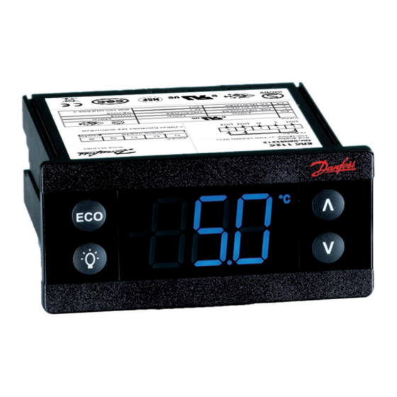
Электронный холодильный контроллер ERC112 со светодиодным дисплеем, специально разработанный для охладителей бутылок, коммерческих холодильников и морозильников. Он особенно подходит для ОЕМ клиентов, так как время, простая и надежная установка и высокое качество важны наряду с гибкостью. Дисплей может быть красным или синим. Контроллер доступен с верхней левой кнопкой «ECO» или «Оттайка». Нижняя левая кнопка может быть «Свет», «Отключение» или «Ускоренное охлаждение».
Документация
Контроллер может настраиваться тремя способами: используя «Программу», при помощи док-станции или вручную посредством кнопок на фронтальной панели. «Программа», лицензированная Данфосс, предлагает простую настройку параметров посредством USB шлюза. Программа поставляется отдельно; для получения технической литературы и дополнительной информации контактируйте с местным представительством Данфосс.
Док-станция поставляется отдельно. Для получения технической литературы и дополнительной информации контактируйте с местным представительством Данфосс.
| Входы | 5 входов: 4 аналоговых (цифровые), 1 цифровой; назначение определяется пользователем | ||
| Световой датчик ЕСО от Данфосс | Дверной датчик: все типы, пользовательские | ||
| Воздух / испаритель / конденсатор | Датчик движения | ||
| Выходы | UL60730 | EN60730 | |
| «DO1» (Реле компрессора) | 120 В перем. ток: 16 A резистивная/FLA16/LRA72 240 В перем. ток: 10 A резистивная/FLA10/LRA60 |
16(16) A | |
| «DO4» | 8 A резистивная, FLA2/LRA12, TV-1 | 8A резистивная, 2(2) A | |
| «DO5» | FLA2/LRA12, TV-1 | 8A резистивная, 2(2) A | |
| «DO6» | FLA2/LRA12, TV-1 | 8A резистивная, 2(2) A | |
| Макс. 10 А всего «DO4-6» | |||
| Датчики | Danfoss NTC и ЭКО аксессуары | ||
| Разъемы | Модульная система разъёмов для ОЕМ-клиентов с опциональным адаптером с винтовыми клеммами. Тип входного разъёма: Rast 2.5 Edge. Тип выходного разъёма: Rast 5 Standard |
||
| Программирование | Программирование с помощью док-станции ERC от Данфосс | ||
| Сборка | 3 типа: фронтальный монтаж; клипсы; полностью интегрированное решение (требуется определённый ОЕМ-дизайн монтажного отверстия) | ||
| Дисплей | Светодиодный, 3-х цифровой, десятичная точка и многофункциональные иконки; шкала ˚С/˚F | ||
| Клавиатура | 4 кнопки (IP65), 2 слева, 2 справа; программируемые пользователем | ||
| Рабочие условия | от 0˚С до 55˚С, относительная влажность 93% | ||
| Условия хранения | от -40˚С до 85˚С, относительная влажность 93% | ||
| Диапазон измерения | от -40˚С до 85˚С | ||
| Защита | Передняя панель: IP65, задняя часть: защита от воды и пыли в соответствии с IP31, доступность на задней панели разъёмов вводит ограничение IP00 | ||
| Окружающая среда | Степень загрязнения II, без конденсации | ||
| Огнестойкость и пожарозащищённость | Категория D (UL94-V0) | ||
| Категория ЭМС | Категория I | ||
| Рабочие циклы | Реле компрессора: более чем 175 000 при полной нагрузке (16А(16А)) | ||
| Сертификация | R290/R600a: заключение о соответствии EN/IEC 60335- 2-24, приложение СС и EN/IEC 60335-2-89, приложение BB Жаропрочный провод в соответствии с EN/IEC 60335- 1 I EC/EN 60730 UL60730 NSF CQC EAC |
Эти сертификаты имеют силу только при использовании разрешенных аксессуаров |


-
Contents
-
Table of Contents
-
Troubleshooting
-
Bookmarks
Quick Links
User Guide
Electronic Refrigeration Controller
ERC 112
This user guide is intended to be used by OEMs for the purpose of
programming ERC 112. It may also be useful for technicians. However, it is not
intended as a user guide for end users.
www.danfoss.com/erc
Related Manuals for Danfoss ERC 112
Summary of Contents for Danfoss ERC 112
-
Page 1
Electronic Refrigeration Controller ERC 112 This user guide is intended to be used by OEMs for the purpose of programming ERC 112. It may also be useful for technicians. However, it is not intended as a user guide for end users. www.danfoss.com/erc… -
Page 2
User Guide | ERC 112 Refrigeration Controller Introduction Temperature control for refrigeration appliances. Application Front panel mounting. The latest generation CPU, plenty of memory Advantages and high-end electronic components allow for a uniquely versatile software. Three separate password-protected user levels can be used to control more than 300 different parameters to fit all individual requirements. -
Page 3: Typical Application
User Guide | ERC 112 Refrigeration Controller Typical application Glass Door Merchandiser No-frost freezer/sub-zero cooler S3, S4 are optional S2, S3, S4 are optional Gastro No-frost freezer/Cooler S3, S4 are optional S2, S3, S4 are optional © Danfoss | DCS (vt) | 2019.07…
-
Page 4: Product Overview
User Guide | ERC 112 Refrigeration Controller Product overview Display The ERC 112 is an electronic refrigeration controller with an LED display especially developed for bottle coolers and commercial fridges and freezers. It is particularly suited for OEM customers where time, easy and reliable installation and high quality need to go hand in hand with flexibility.
-
Page 5: Quick Programming
User Guide | ERC 112 Refrigeration Controller Quick programming Software for PC KoolProg Software from Danfoss for programming the ERC-controller via a PC rather than with the front panel buttons. https://www.danfoss.com/en/service-and- support/downloads/dcs/koolprog/ USB gateway USB gateway The USB Gateway is a laboratory tool, offering fast and easy programming of any ERC controller connected directly to the PC.
-
Page 6: Technical Specs
FLA2/LRA12, TV-1 8 A resistive, 2(2) A Max 10 A total «DO4-6» Danfoss NTC sensors and Danfoss ECO accessories (Light, Motion and Door sensors) Probes Danfoss Pt 1000 ohm/0°C Modular connector system for OEM customers, with optional output screw terminal adapter;…
-
Page 7
User Guide | ERC 112 Refrigeration Controller Connections ERC 112C (3 relays) (Inputs and outputs are configurable) ERC 112D (4 relays) Note S4 Port can also be used to connect other sensors and Door sensor. © Danfoss | DCS (vt) | 2019.07… -
Page 8: Code Numbers
User Guide | ERC 112 Refrigeration Controller Code numbers Type I-Pack Type I-Pack Qty. Code no. Qty. Code no. ERC 112C, Red LED, without 080G3202 -100 – 200 °C, Pt 1000 buzzer S4, 1000 mm, 3-pole 080G3350 ERC 112D, Red LED, without…
-
Page 9: Manual Operation With Buttons (Direct Access)
User Guide | ERC 112 Refrigeration Controller Operation The controller can be configured in four ways: All these tools are supplied separately. Programming Tools Using: For technical literature and further information, • KoolProg and KoolKey as Gateway please contact your local Danfoss representative.
-
Page 10: Fan Settings
Min. -100.0°C In standard operation the set point is changed by simply pressing the Max. 200.0°C «temperature up/down» buttons on ERC 112; for laboratory and Default 2.0°C assembly line you may opt for software controlled set point adjustment (speed improvement) «SPr»…
-
Page 11
User Guide | ERC 112 Refrigeration Controller «FSt» Fan Minimum Stop time Minimum stop time for fan protection. Min. 0 s Max. 960 s Default 10 s «FdC» Fan Δt cut in (This parameter is only applicable with Automatic fan control «Aut» mode.) Min. -
Page 12
User Guide | ERC 112 Refrigeration Controller «Pdi» Pull Down Defrost Interval This is the time between defrost cycles during pull down. It is measured in hours and can be up to 48 hours. Min. 0 hour During pull down, this setting overrides the defrost interval and defrost time settings (see the defrost section). -
Page 13
User Guide | ERC 112 Refrigeration Controller «dot» Drip OFF Time This parameter can be set to between 0 and 60 minutes and defines how long the delay is between the heater being switched Min. 0 min OFF and the compressor starting again. -
Page 14: Compressor Settings
User Guide | ERC 112 Refrigeration Controller Compressor settings «uPt» Voltage protection «no»: no voltage protection. «yES»: voltage protection activated based on voltage related settings. Min. no Max. yes Default no «uLi» Minimum cut-in voltage/uLi. Minimum cut-out voltage/uLo. Maximum voltage/uHi Min.
-
Page 15
The controller can have its display intensity (brightness) set in one of Min. 2 two ways: Max. 10 A) With a Danfoss ambient light sensor attached, the brightness of the Default 10 display is adjusted automatically according to the ambient light level (see the assignments section). -
Page 16: Display Unit
User Guide | ERC 112 Refrigeration Controller «CFu» Display Unit This parameter sets the display to Fahrenheit or Celsius. Switching from Min. °C one to the other will cause all temperature settings to be automatically Max. °F updated accordingly. Default °C «trS»…
-
Page 17
User Guide | ERC 112 Refrigeration Controller «SdF» Show Defrost If set to «yES», this parameter causes the display to show DEF when the Min. no system is in defrost mode. If set to «nO», the temperature continues to Max. yes be displayed. -
Page 18
User Guide | ERC 112 Refrigeration Controller «Pdd» Pull down delay Normally, it is not necessary or desirable to sound an alarm during a pull Min. 0 min down (the initial phase of reaching the desired temperature). This Max. 960 min Default 240 min parameter prevents the high temperature alarm «HAt»… -
Page 19
Default 2.0 K ECO strategy NOTE: some of these parameters require the installation of the Danfoss Ambient Light Sensor. The Danfoss USB Gateway in combination with «KoolProg Software» allows for real time measurement of the current light intensity. Danfoss recommends test- ing and adjusting «SLd»… -
Page 20
User Guide | ERC 112 Refrigeration Controller «Euu» EWU active on/OFF Enable or disable early wake up. Min. no Max. yes Default yes «CLH» Shop close hour Shop is assumed to be closed when staying in ECO mode longer than shop close hour. -
Page 21
Please contact your local Danfoss representative for information about default settings. NOTE: coded sensors will impact on the number of possible configurations. For instance: Danfoss supplies only 2-pole defrost sensors, so input «S3» will most likely be used as a defrost/evaporator temperature sensor input. «S1C» S1 Config/S1C… -
Page 22
User Guide | ERC 112 Refrigeration Controller «diC» DI Config This is the digital input used for a digital sensor or bus communications. Default non «non»: not used. «doC»: door contact, contact closed when door closed. «doo»: door contact, contact open when door closed. -
Page 23
You may not therefore have access to change all the passwords. Passwords are entered by using the up and down arrow buttons. Min. 0 Max. 999 Danfoss advises against using passwords which are easy to remember Default 0 or enter, for example 111, 222, 123 etc. «PS3″… -
Page 24
User Guide | ERC 112 Refrigeration Controller «HAr» HW version Danfoss hardware version number. «onL» OrderNoLow Danfoss order code number. «onH» OrderNoHigh Danfoss order code number. «oEL» OEM code Low «oEn» OEM code Middle «oEH» OEM code High «PAr» Parameter version OEM parameter version number [requires EKA copy key update]. -
Page 25: Troubleshooting
User Guide | ERC 112 Refrigeration Controller Troubleshooting Problem Probable cause Remedy Compressor does not start Waiting for compressor delay timer Check CoP->CSt Defrost in progress Check CoP ->Pot /Pod Line voltage to compressor too low Check dEF ->dit, dot or too high Check CoP->uLi, uLo, uHi…
-
Page 26: Typical Applications
User Guide | ERC 112 Refrigeration Controller Typical applications Glass Door Merchandiser, No-frost freezer/sub-zero cooler Note: this is a typical (default) wiring diagram since both inputs (AI/DI’s) and outputs (DO’s) can be assigned differently. Please see «ASi», assignment ERC 112D…
-
Page 27
User Guide | ERC 112 Refrigeration Controller Gastro No-frost freezer ERC 112D Controller Red LED with buzzer 080G3213 Red LED with buzzer 080G3217 Temperature Sensor for Temperature Sensor for Temperature Sensor for Cabinet Temperature Evaporator Temperature Condenser Temperature Door input… -
Page 28: Application Matrix
User Guide | ERC 112 Refrigeration Controller Application Matrix ERC 112 Output Input Application ERC type Standard beverage Condenser or Ambient Door or Motion ERC 112C Comp Lamp Control Defrost cooler Light or Motion detection detection Sub-zero beverage Condenser or Ambient…
-
Page 29: Sensor Placement
User Guide | ERC 112 Refrigeration Controller Sensor placement Control sensor The control sensor must always be connected and is used for controlling the cut-in and cut-out of the compressor according to the set point. The sensor is also used for the displayed temperature.
-
Page 30: Condenser Sensor
User Guide | ERC 112 Refrigeration Controller Condenser sensor The condenser sensor is used to protect the compressor against high pressure when the condenser is blocked or the condenser fan fails. Condenser sensor Place the sensor at the liquid side of the condenser.
-
Page 31
User Guide | ERC 112 Refrigeration Controller © Danfoss | DCS (vt) | 2019.07 BC200686422115en-000802 | 31… -
Page 32
© Danfoss | DCS (vt) | 2019.07 BC200686422115en-000802 | 32…
Описание ERC 112С, Контроллер температуры — 080G3202
| Напряжение питания | 230 В перем.тока 50Гц; 1,5 ВА |
| Управление компрессором | да |
| Управление оттаиванием | да |
| Поддержка сетевых карт | нет |
| Гарантийные обязательства | Изготовитель/продавец гарантирует соответствие контроллеров техническим требованиям при соблюдении потребителем условий транспортирования, хранения и эксплуатации.Гарантийный срок эксплуатации и хранения контроллеров – 12 месяцев с даты продажи, указанной в транспортных документах, или 18 месяцев с даты производства.Срок службы оборудования при соблюдении рабочих диапазонов согласно паспорту/инструкции по эксплуатации и проведении необходимых сервисных работ — 10 лет с даты продажи, указанной в транспортных документах. |
| температура среды при эксплуатации | 0 до +55 °С |
| Число испарителей | 1 |
| Управление вентилятором | да |
| Управление светом | да |
| Количество цифровых входов | 1 |
| температура среды при хранении | от -40 до +85 °С |
| Количество входов | 4 Входа 3 аналоговых и 1 цифровой – назначаются пользователем |
| Количество реле | 3 (компрессор: 16A остальные реле: 8A) |
| Модель | ERC112C |
| Назначение изделия | Контроллеры температуры типа ERC модификации 112 (далее – контроллеры типа ERC) используются для управления испарителем холодильной установки для поддержания заданной температуры, а также для управления его режимом оттаивания, и управления дополнительными функциями холодильного оборудования. |
| Количество аналоговых выходов | 0 |
| Встроенная сетевая карта | нет |
| Количество аналоговых входов | 3 |
| Комплектность | В комплект поставки входят:-контроллер температуры типа ERC;-инструкция. |
Технические характеристики ERC 112С, Контроллер температуры — 080G3202
| Встроенная сетевая карта | нет |
|---|---|
| Количество аналоговых входов | 3 |
| Количество аналоговых выходов | |
| Количество входов | 4 Входа 3 аналоговых и 1 цифровой – назначаются пользователем |
| Количество реле | 3 (компрессор: 16A остальные реле: 8A) |
| Количество цифровых входов | 1 |
| Модель | ERC112C |
| Напряжение питания | 230 В перем.тока 50Гц; 1,5 ВА |
| Поддержка сетевых карт | нет |
| температура среды при хранении | от -40 до +85 °С |
| температура среды при эксплуатации | 0 до +55 °С |
| Управление вентилятором | да |
| Управление компрессором | да |
| Управление оттаиванием | да |
| Управление светом | да |
| Число испарителей | 1 |
-
Contents
-
Table of Contents
-
Troubleshooting
-
Bookmarks
Quick Links
ERC 112 refrigeration controller
Bottle cooler controller
ERC 112
This reference manual is intended to be used primarily by OEMs for the purposes
of programming ERC 112. It may also be useful for technicians. It is not intended
as a user guide for end users.
www.danfoss.com/erc
Related Manuals for Danfoss erc 112
Summary of Contents for Danfoss erc 112
-
Page 1
Bottle cooler controller ERC 112 This reference manual is intended to be used primarily by OEMs for the purposes of programming ERC 112. It may also be useful for technicians. It is not intended as a user guide for end users. www.danfoss.com/erc… -
Page 2
Passwords for the different levels can however be altered for the level of access you have, e.g. a level 2 user can change the password for level 1 and level 2 but not level 3. DKRCC.ES.RL0.D5.02 / 520H8676 Produced by Danfoss A/S (EL-MSSM/AZ) | April 2014… -
Page 3
No-frost freezer/sub-zero cooler S3, S4 are optional Glass Door Merchandiser S2, S3, S4 are optional Gastro No-frost freezer S3, S4 are optional Gastro Cooler S2, S3, S4 are optional Produced by Danfoss A/S (EL-MSSM/AZ) | April 2014 DKRCC.ES.RL0.D5.02 / 520H8676… -
Page 4
User manual ERC 112 refrigeration controller Product overview Display The ERC 112 is an electronic refrigeration controller with an LED display especially developed for bottle coolers and commercial fridges and freezers. It is particularly suited for OEM customers where time, easy and reliable installation and high quality need to go hand in hand with flexibility. -
Page 5
Quick programming Software for PC Software tool Software from Danfoss for programming the ERC 112 via a USB gateway and a PC rather than with the front panel buttons. USB gateway USB gateway The USB Gateway is a laboratory tool, offering fast and easy programming of any ERC controller connected directly to the PC. -
Page 6
Input connector type: Rast2 5 Edge connectors; output connector type: RAST 5 standard Programming Programming with Danfoss ERC docking station, integrated system Assembly 3 types for all controls: front mounting; brackets; fully integrated solution (requires OEM specific design of mounting hole) Display LED display, 3 digit, decimal point and multi functionality icons;… -
Page 7
User manual ERC 112 refrigeration controller Connections ERC 112C (3 relays) ERC 112D (4 relays) Produced by Danfoss A/S (EL-MSSM/AZ) | April 2014 DKRCC.ES.RL0.D5.02 / 520H8676… -
Page 8
S3, 3000 mm, 3-pole 077F8768 S3, 6000 mm, 3-pole 080G2039 Note: For more information about temperature sensor types and connectors, please refer to Danfoss’ technical Sx (di)= connector position. brochure «NTC type temperature sensors for ETC & ERC Inputs are configurable. controllers». -
Page 9
2. Level 2: «ser» (service technician). case of temperature-sensitive food storage, 3. Level 3: «OEM» (OEM programming). breaches in food hygiene principles and regulations. Only a trained operator should make changes to parameters. Produced by Danfoss A/S (EL-MSSM/AZ) | April 2014 DKRCC.ES.RL0.D5.02 / 520H8676… -
Page 10
Min. -100.0°C In standard operation the set point is changed by simply pressing the Max. 200.0°C «temperature up/down» buttons on ERC 112; for laboratory and Default 2.0°C assembly line you may opt for software controlled set point adjustment (speed improvement) «SPr»… -
Page 11
For each hour the Max. 10.0 K cabinet temperature is above the pull down initiate temperature, Default 0.1 K the set point is reduced with the value of «Prt». Produced by Danfoss A/S (EL-MSSM/AZ) | April 2014 DKRCC.ES.RL0.D5.02 / 520H8676… -
Page 12
Defrost settings «dFt» Defrost Type «no»: defrost function is disabled. Default no «EL»: electrical or time defrost. «Hgd»: hot gas defrost (contact Danfoss for details). «nat»: OFF-cycle defrost (natural defrost). «Add» Adaptive defrost «no»: defrost controlled by time. Min. no «yES»: automatic defrost control activated. -
Page 13
OFF. «EHd» Sensor Error Type «no»: no sensor error handling. Default no «SEt»: in case of control sensor error, follow error run/stop time. «Aut»: automatical sensor error handling. Produced by Danfoss A/S (EL-MSSM/AZ) | April 2014 DKRCC.ES.RL0.D5.02 / 520H8676… -
Page 14
NOTE: A condensor temperature sensor is required to use these parameters. Condenser protection is generally used in dusty environments where the condenser may accumulate a layer of dust or dirt and therefore be at risk of overheating. DKRCC.ES.RL0.D5.02 / 520H8676 Produced by Danfoss A/S (EL-MSSM/AZ) | April 2014… -
Page 15
The controller can have its display intensity (brightness) set in one of Min. 2 two ways: Max. 10 A) With a Danfoss ambient light sensor attached, the brightness of the Default 10 display is adjusted automatically according to the ambient light level (see the assignments section). -
Page 16
«yES»: show defrost symbol on display. Max. yes Default yes «SES» Show ECO symbol «no»: ECO symbol will not show on display. Min. no «yES»: show ECO symbol on display. Max. yes Default yes DKRCC.ES.RL0.D5.02 / 520H8676 Produced by Danfoss A/S (EL-MSSM/AZ) | April 2014… -
Page 17
In some cases, it may be necessary for a user or technician to take action in order to clear the alarm. If set to 0, the alarm will never sound. Produced by Danfoss A/S (EL-MSSM/AZ) | April 2014 DKRCC.ES.RL0.D5.02 / 520H8676… -
Page 18
ECO strategy NOTE: some of these parameters require the installation of the Danfoss Ambient Light Sensor. The Danfoss USB Gateway in combination with «Software tool» allows for real time measurement of the current light intensity. Danfoss recommends testing and adjusting «SLd» and «SLn»… -
Page 19
ERC 112 refrigeration controller «ECt» Action counter time Door action or «PIR» action within action counter time can trigger Min. 0 min exiting ECO (can only be accessed by Danfoss). Max. 180 min Default 30 min «Edd» Door delay Door delay after door close to trigger entering ECO Min. -
Page 20
NOTE: coded sensors will impact on the number of possible configurations. For instance: Danfoss supplies only 2-pole defrost sensors, so input «S3» will most likely be used as a defrost/evaporator temperature sensor input. DKRCC.ES.RL0.D5.02 / 520H8676 Produced by Danfoss A/S (EL-MSSM/AZ) | April 2014… -
Page 21
Default dEF D04 Config/o4C «no»: not used. «o3C» «dEF»: electric defrost heater/valve for hot gas. Default FAn «ALA»: alamr output. «FAn»: fan control. «o4C» «Lig»: light control. Default Lig Produced by Danfoss A/S (EL-MSSM/AZ) | April 2014 DKRCC.ES.RL0.D5.02 / 520H8676… -
Page 22
You may not therefore have access to change all the passwords. Passwords are entered by using the up and down arrow buttons. Min. 0 Max. 999 Danfoss advises against using passwords which are easy to remember Default 0 or enter, for example 111, 222, 123 etc. «PS3″… -
Page 23
Resets all parameters to last good OEM settings. «Ctt» Condenser Temp Temperature of the condensor sensor. «Et1» Evaporator1 Temp Temperature of the evaporator sensor1. «Et2» Evaporator2 Temp Temperature of the evaporator sensor2. Produced by Danfoss A/S (EL-MSSM/AZ) | April 2014 DKRCC.ES.RL0.D5.02 / 520H8676… -
Page 24
Device has not finished programming (relay output is lockt) «Eco» Device is in Eco mode «SC» Device is in pull-down mode (super-chill) «dEF» Device is defrosting «HoL» Device is in Holiday mode DKRCC.ES.RL0.D5.02 / 520H8676 Produced by Danfoss A/S (EL-MSSM/AZ) | April 2014… -
Page 25
Blink «E03». If configured: cut in alarm relay, beep the buzzer «S3» sensor failure (short or open) «E04» «S4» error Always Blink «E04». If configured: cut in alarm relay, beep the buzzer «S4» sensor failure (short or open) Produced by Danfoss A/S (EL-MSSM/AZ) | April 2014 DKRCC.ES.RL0.D5.02 / 520H8676… -
Page 26
3000 mm 077F8798 3000 mm 077F8768 4000 mm 080G3393 4000 mm 080G3343 2200 mm 077F8767 6000 mm 080G2029 6000 mm 080G2039 3000 mm 077F8769 3500 mm 077F8723 6000 mm 080G2019 DKRCC.ES.RL0.D5.02 / 520H8676 Produced by Danfoss A/S (EL-MSSM/AZ) | April 2014… -
Page 27
2000 mm 077F8765 3000 mm 077F8798 3000 mm 077F8768 4000 mm 080G3343 077F8767 080G2029 080G2039 2200 mm 6000 mm 6000 mm 3000 mm 077F8769 077F8723 3500 mm 6000 mm 080G2019 Produced by Danfoss A/S (EL-MSSM/AZ) | April 2014 DKRCC.ES.RL0.D5.02 / 520H8676… -
Page 28
• Condenser sensor or light sensor are optional and can be omitted. • Defrost sensor is mandatory when electrical heater is used for defrost. For natural defrost it can be omitted. DKRCC.ES.RL0.D5.02 / 520H8676 Produced by Danfoss A/S (EL-MSSM/AZ) | April 2014… -
Page 29
The evaporator sensor is only used for de-icing of the evaporator and has no control purpose. Placement of sensor Place the sensor where the ice melts last. Please be aware of that sharp finns can damage the cable. Produced by Danfoss A/S (EL-MSSM/AZ) | April 2014 DKRCC.ES.RL0.D5.02 / 520H8676… -
Page 30
The door sensor is used to detect buying activity and to stop the fan when the door is opened. Door sensor Danfoss does not supply the door-switch. Use the door-switch you have and connect it to the cable supplied by Danfoss. -
Page 31
User manual ERC 112 refrigeration controller Produced by Danfoss A/S (EL-MSSM/AZ) | April 2014 DKRCC.ES.RL0.D5.02 / 520H8676… -
Page 32
ERC 112 refrigeration controller Danfoss can accept no responsibility for possible errors in catalogues, brochures and other printed material. Danfoss reserves the right to alter its products without notice. This also applies to products already on order provided that such alternations can be made without subsequential changes being necessary in specifications already agreed.
DKRCE.PI.RL0.A2.02 / 520H10340© Danfoss | DCS (az) | 2015.09 Installation guide | ERC 112
36.5 mm
28 mm
78.25 mm
82.25 mm
78.25 mm
71 mm
28.5 mm
71 mm
30 mm
1
S1 S2 S3 S4 di
DO1
Outputs
Inputs
ERC 112D
100 – 240 V AC ± 10% 50/60 Hz 0T55
LNDO2 DO3 DO4
2 3 4 5 6 1
S1 S2 S3 S4 di
DO1
Outputs
Inputs
ERC 112C
100 – 240 V AC ± 10% 50/60 Hz 0T55
LNDO2 DO3
2 3 4 5
SC
SC
^
^
^
^
ECO
Installation Guide
ERC 112
Bottle Cooler Controller
Power Supply 100 – 240 V AC Switch mode power supply. Average 0.7 W
Input
5 inputs: 4 analogue (digital), 1 digital; user specific assignment
• Air / Evaporator / Condenser • Door sensor: all types, user specific
• Light sensor: Danfoss ECO light
sensor
• Motion sensor
Output
UL60730 EN60730
«DO1»
(Compressor relay)
120 V AC: 16 A resistive /
FLA 16/LRA 72
240 V AC: 10 A resistive /
FLA 10 / LRA 60
16(16) A
«DO4»
8 A resistive, FLA 2 / LRA
12, TV-1
8 A resistive, 2(2) A
«DO5» FLA 2 / LRA 12, TV-1 8 A resistive, 2(2) A
«DO6» FLA 2 / LRA 12, TV-1 8 A resistive, 2(2) A
Max 10 A total «DO4-6»
Probes
• Danfoss NTC sensors and Danfoss ECO accessories
• Danfoss PT1000 ohm / 0°C
Connectors
• Modular connector system for OEM customers, with optional output screw
terminal adapter
• Input connector type: Rast2 5 Edge connectors
• output connector type: RAST 5 standard
Programming Programming with Danfoss ERC docking station, integrated system
Assembly
3 types for all controls:
front mounting; brackets; fully integrated solution
(requires OEM specific design of mounting hole)
Display LED display, 3 digit, decimal point and multi functionality icons; °C / °F scale
Keypad 4 buttons (integrated IP65 design), 2 left, 2 right; user programmable
Operating
Conditions
0 °C – 55 °C, 93% rH
Storage
Conditions
-40 °C – 85 °C, 93% rH
Range of
Measurement
-40 °C – 85 °C
Protection
Front: IP65
Rear: water and dust protection corresponds to IP31,
accessibility of connectors limit rear part rating to IP00
Environmental Pollution degree II, non-condensing
Resistance to
heat & re
Category D (UL94-V0)
EMC category Category I
Operating Cycles Compressor relay: more than 175.000 at full load (16 A (16 A))
Approvals
• R290 / R600a end-use applications
employing in accordance to
EN / IEC 60335-2-24, annex CC and
EN / IEC 60335-2-89, annex BB
• Glow wire according to
EN / IEC 60335-1 / IEC / EN 60730
• UL60730
• NSF
• CQC
• GOST R 60730
• These approvals are only valid when
using the accessories approved
Technical specication
Menu structure Operation Changing the setpoint:
Two kinds of left buttons — see pictures 1. and 3.
Example of changing a parameter Turning ON/OFF the ECO function
Password protection
Acknowledging alarm
Activating manual defrost
Dimensions
Wiring diagram
Conguration of outputs
Conguration of inputsConguration of inputs
ERC front and button functionality
Functional description of used sensors
Front mounting
(Lock with frame)
Rear mounting
(Lock with clips)
Relay
outputs
Compress. Defrost Fan Light Alarm
Heating
application
DO1 (o1C)
DO2 (o2C)
DO3 (o3C)
DO4 (o4C)
Input/
sensor
Cabinet
sensor
Evapor.
sensor
Conden.
sensor
Door
sensor
Light
sensor
Movem.
sensor
Comm.
S1
S2
S3
S4
di
Control temperature sensor
The control sensor must always be connected and is used for controlling the cut-in and cut-out of
the compressor according to the set-point. The sensor is also used for the displayed temperature.
Most common placement is in the return air to the evaporator.
Evaporator sensor
The evaporator sensor is only used for de-icing of the evaporator and has no control purpose.
Place the sensor where the ice melts last.
Please be aware of that sharp fins can damage the cable.
Condenser temperature sensor
The condenser sensor is used to protect the compressor against high pressure when the
condenser is blocked or the condenser fan fails.
Place the sensor at the liquid side of the condenser. Use a metal bracket or metal tape to ensure
good thermal conductivity. Be sure that the cable does not pass hot spots at the compressor or
condenser that exceeds 80 °C.
Congurable functionality
Button
Basic
function
Not
operating
ON/OFF
Increase
setpoint
Decrease
setpoint
Toggle
defrost
Toggle
light
1 press OK
1 pess and hold
2 press BACK
2 pess and hold
3 press UP
3 pess and hold
4 press DOWN
4 pess and hold
Congurable functionality
Button
Toggle
ECO
Toggle
pulldown
Increase
display
intensity
Decrease
display
intensity
Toggle °C
or F
Info menu
1 press
1 pess and hold
2 press
2 pess and hold
3 press
3 pess and hold
4 press
4 pess and hold
Press and
hold 5 sec to
access the
menu
1. Parameter group
1. Parameter name
Lower left button
Lower left button
Scroll through parameters
Scroll through menu group
The display shows the current temperature
Current temperature
1.
1.
2.
2.
3.
3.
Flashing temperature setpoint
Press: UP/DOWN to adjust setup
After 30 seconds, the display automatically
reverts to showing the current temperature
Defrost symbol is shown in defrost mode
Defrost symbol will disappear after the defrost is
finished.
(The dEF text during the defrost is displayed or
not based on the cabinet manufacturer settings)
Press briefly
to start or
stop defrost
1.
2.
3.
4.
5.
6.
7.
8.
9.
Press and hold 5 sec to access
the menu
Press: UP / DOWN to scroll
through the menu
Press: UP / DOWN to find the
desired parameter
Press: UP / DOWN to enter the
desired value
To select: press the lower
left button (OK)
To confirm: press the lower
left button (OK)
To accept: press the lower left
button (OK) and return to
parameter name
To exit without accept:
press the upper left button (BACK)
To return to parameter group:
press upper left button (BACK)
To return to menu:
press upper left button (BACK)
After 30 seconds of inactivity,
the display automatically
reverts to showing the current
temperature
Scroll through parameters group
Scroll through group «dEF» parameters
1.
2.
The green ECO symbol is list
when in ECO mode
Press briefly to enter
ECO mode
Password protection on three levels:
LEVEL 1: shop (daily use by shop personnel)
LEVEL 2: ser (service technician)
LEVEL 3: OEM (OEM programming
Press and hold 5
sec to access the
menu
1.
2.
The alarm code flashing alternately
with the temperature and the
alarm symbol is displayed
After the acknowledge the
temperature is displayed and the
alarm symbol remains shown
Press any button to acknowlege