-
Contents
-
Table of Contents
-
Bookmarks
Quick Links
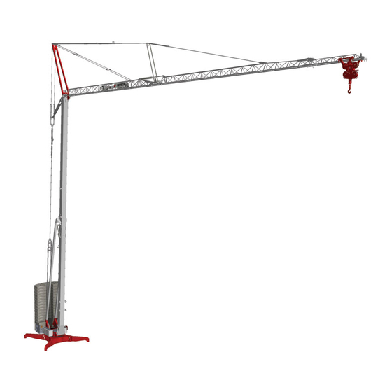
Self-Erecting
Tower Crane
CBR 40H
4
–
REV.000-1
O p e r a t i n g I n s t r u c t i o n s — I n s t a l l a t i o n
M a i n t e n a n c e
Related Manuals for Terex CBR 40H-4
Summary of Contents for Terex CBR 40H-4
-
Page 1
Self-Erecting Tower Crane CBR 40H – REV.000-1 O p e r a t i n g I n s t r u c t i o n s — I n s t a l l a t i o n M a i n t e n a n c e… -
Page 3
FOREWORD This publication must be read carefully by the personnel assigned to the crane before taking any action. Only by meticulously following the instructions given in this manual will the crane be able over time to provide the high performance for which it has been designed and constructed. The manual highlights important information for the safety of persons and conservation of the machine with the following wording: WARNING: When failure to observe or incorrect observation of the prescribed instructions… -
Page 4: Table Of Contents
TABLE OF CONTENTS T A B L E O F C O N T E N T S 1 MAIN CHARACTERISTICS page 1.1 MARKING 1.01 1.1.1 MANUFACTURER 1.01 1.1.2 TYPE OF MACHINE 1.01 1.1.3 CE MARKING 1.02 1.1.4 NOISE EMISSION MARKING 1.02 1.1.5 IDENTIFICATION PLATE…
-
Page 5
TABLE OF CONTENTS 1.4.5 MECHANISMS 1.22 1.4.5.1 HOISTING 1.22 1.4.5.2 TROLLEY TRAVERSING 1.23 1.4.5.3 SLEWING 1.23 1.4.5.4 ERECTION 1.24 1.4.6 HYDRAULIC DIAGRAM 1.25 1.4.7 PRECAUTIONS WHEN USING THE HYDRAULIC SYSTEM 1.26 1.4.8 CONTROL MEMBERS 1.27 1.4.8.1 MAIN SWITCH 1.27 1.4.8.2 PUSHBUTTON PANEL 1.28 1.4.9 COUNTERWEIGHT BALLAST… -
Page 6
TABLE OF CONTENTS 3 ERECTION — USE — DISMANTLING page 3.1 INSTRUCTIONS FOR POSITIONING AND ERECTION 3.01 3.1.1 ELECTRICAL CONNECTION 3.01 3.1.2 POSITIONING THE CRANE 3.04 3.1.3 PREPARING THE JIB 3.06 3.1.4 TOWER ERECTION 3.07 3.1.5 BALLASTING 3.08 3.1.6 JIB ALIGNMENT 3.10 3.2 SAFETY DEVICES — FUNCTION AND SETTING 3.13… -
Page 7
TABLE OF CONTENTS 4 MAINTENANCE page 4.1 MAINTENANCE INSTRUCTIONS 4.01 4.1.1 GENERAL 4.01 4.1.2 MAINTENANCE SCHEDULE 4.01 4.1.3 SLEWING RING 4.04 4.1.4 TROLLEY ROPE TENSIONING 4.04 4.1.5 CHECKING THE ROPES 4.05 4.1.6 LUBRICATION 4.06 4.1.7 STORING THE CRANE 4.06 4.2 INSTRUCTIONS FOR ROUTINE REPAIRS 4.07 4.2.1 GENERAL TROUBLE OF AN ELECTRICAL NATURE… -
Page 9: Main Characteristics
Self-Erecting Tower Crane CBR 40H – REV.000-1 — MAIN CHARACTERISTICS…
-
Page 11: Marking
TOWER CRANE intended to hoist off a rigid surface and move through the air an unguided unit load hanging directly from the hook with the permissible hoisting or slinging accessories in between. CBR 40H-4 MODEL….SERIAL No……….YEAR OF MANUFACTURE……
-
Page 12: Ce Marking
1 MAIN CHARACTERISTICS 1.1.3 CE MARKING The crane bears the CE marking for conformity with the Machinery Directive 98/37/EC and subsequent amendments. The marking is on the data plate on the door of the electric box The original signed «EC Declaration of Conformity» is delivered with the crane. This document is an integral part of the machine;…
-
Page 13: Identification Plate
1 MAIN CHARACTERISTICS 1.1.5 IDENTIFICATION PLATE The data plate shown below is on the door of the electric box. It bears the crane’s specifications as well as its identification data. The data plate is an integral part of the machine and must not be removed until the machine is dismantled.
-
Page 14: Foreword
1 MAIN CHARACTERISTICS FOREWORD 1.2.1 SCOPE AND LIMITS OF THE MANUAL This manual is mainly intended for the owners of cranes and their site managers and in general all operators involved in moving, installing, using and servicing the crane. The purpose of this manual is to provide information on: •…
-
Page 15: Supplements And Updates To The Manual
1 MAIN CHARACTERISTICS 1.2.3 SUPPLEMENTS AND UPDATES TO THE MANUAL This manual represents the state of technology at the time of marketing the crane to which it refers; it must not be considered inadequate just because it has been subsequently updated in the light of new experience. Comedil reserves the right to modify its production and associated manuals without moreover being bound to update what was previously delivered.
-
Page 16: Intended Conditions Of Use
1 MAIN CHARACTERISTICS INTENDED CONDITIONS OF USE 1.3.1 DESCRIPTION OF THE EQUIPMENT The tower crane described in this manual is a device for hoisting and transportation intended solely for professional use. General characteristics: • slewing: at the bottom • installation method: in fixed position •…
-
Page 17
1 MAIN CHARACTERISTICS 1000 kg 38.8 m 1000 kg 39.5 m WARNING: When the jib is raised by 10° and 15° it is permissible to use the 2-part line only. CBR 40H page 1.07 rev. 40H_1i_07… -
Page 18
1 MAIN CHARACTERISTICS CAPACITY DIAGRAMS Radius 40 m 2/4-part line 4000 3000 2500 2000 1850 1600 1200 1000 13.0 16.5 19.2 23.0 24.5 27.6 34.7 raised 10° (2-part line only) 2000 1850 1600 1200 1000 22.7 24.2 27.3 34.3 39.5 raised 15°… -
Page 19
1 MAIN CHARACTERISTICS movement speed (m/min) capacity (kg) power (kW) micro 6 2000 2-part line slow 23 2000 fast 1000 HOISTING micro 3 4000 4-part line slow 11.5 4000 fast 2000 TROLLEY TRAVERSING 16 / 46 4000/2000 SLEWING 0.3 — 0.9 rpm 1.1 (6 daNm) ERECTION Necessary electric power at… -
Page 20: Operating Environment
1 MAIN CHARACTERISTICS 1.3.4 OPERATING ENVIRONMENT The recommended operating environment is the following: temperature — 5 to 40 °C maximum relative humidity maximum wind speed: • in operation 72 km/h • during erection 30 km /h • out of service 102 km/h on the ground 151 km/h above 20 m in height 1.3.5…
-
Page 21: Operational Control
1 MAIN CHARACTERISTICS 1.3.8 OPERATIONAL CONTROL The operator must always have a direct view of both the load, from gripping to depositing, and the sling. In addition, all the movable parts of the equipment must be visible. If the load is not visible, the operator must receive the operating instructions from an appointed person trained for this function who can see the load.
-
Page 22: Control Elements
1 MAIN CHARACTERISTICS 1.3.9 CONTROL ELEMENTS 1.3.9.1 Pushbutton panel with cable The pushbutton panel is equipped with recessed operating buttons bearing the symbol of the control and an emergency (mushroom-head) button, equipped with an automatic shutdown and reset device with intentional operation. NOTE: The crane can also be operated with a radio-controlled pushbutton panel or manipulator.
-
Page 23: Stopping Movements
1 MAIN CHARACTERISTICS 1.3.11 STOPPING MOVEMENTS The movements are intentionally stopped by releasing the respective control buttons or operating the emergency stops. The up and down movements and the movements of trolley traversing and slewing are progressively stopped in a preset time controlled by an inverter; the mechanical brake only triggers after the movement has stopped.
-
Page 24: Permissible Hoisting Accessories
1 MAIN CHARACTERISTICS 1.3.13 PERMISSIBLE HOISTING ACCESSORIES The hoisting accessories must have a suitable capacity for the extent of the loads to hoist. Hoisting accessories that are simply, in a passive manner, placed between the hook and the load are generally permissible, such as for example: manual opening grabs, forks for pallets, baskets, etc.
-
Page 25: Potential Non-Permissible Uses Of The Cranes
1 MAIN CHARACTERISTICS 1.3.15 POTENTIAL NON-PERMISSIBLE USES OF THE CRANES (see attached diagrams) 1000 4000 1100 4100 Do not hoist loads that exceed the crane’s capacity. Do not hoist at an angle or tow the load. Do not use «rapid» hoisting for loads greater than the permissible ones.
-
Page 26
1 MAIN CHARACTERISTICS Do not lift the load off unstable supporting Do not lift loads hooked outside the surfaces (dangerous scaffolding, watercraft axis of the centre of gravity when there may etc). be tipping over or wild swinging of the load Do not swing a hanging load to deposit Do not make any up or down movements it outside the crane’s range of action. -
Page 27
1 MAIN CHARACTERISTICS Do not use the counter-manoeuvre (do not start Do not pass the load over work areas a manoeuvre if the dynamic effects of the opposite or passageways. preceding manoeuvre have not ended). Do not make any manoeuvres with the load in a Do not affix on the equipment any banners, signs, position where it is not visible. -
Page 28
1 MAIN CHARACTERISTICS Never tow the crane (on rollers or the like) Do not unload from vehicles any weights greater when erected (for working requirements in larger areas) than those permitted by utilizing the forward movement of the vehicle. Do not use the crane for demolition in general. Do not leave the hook constrained to a weight resting or stuck on the ground when the crane is out of service. -
Page 29: Technical Description
1 MAIN CHARACTERISTICS TECHNICAL DESCRIPTION 1.4.1 MAIN COMPONENTS The main components of the crane are listed and identified in the following diagram Undercarriage with arms, screw jacks and stabilizer supports. Platform with slewing unit, hydraulic power pack and electrical equipment Ballast composed of erection block and completion blocks Lower tower section…
-
Page 30: Description Of The Structures
1 MAIN CHARACTERISTICS 1.4.2 DESCRIPTION OF THE STRUCTURE The fixed undercarriage and revolving slewing platform are composed of electric welded plates and sections and are constrained together by the slewing ring. The surfaces are protected by painting composed of a rustproofing coat on which a coat of synthetic paint is applied.
-
Page 31
1 MAIN CHARACTERISTICS 1.4.4.1 Rope diagram 1.4.4.1 Rope diagram TROLLEY ROPE HOISTING ROPE Rope socket 2-PART LINE 4-PART LINE Hoisting rope drum Trolley rope drum CBR 40H page 1.21 rev. 40H_1i_21… -
Page 32
1 MAIN CHARACTERISTICS 1.4.5 MECHANISMS 1.4.5.1 Hoisting The hoisting winch is fitted on the lower tower section and comprises: motor , three-phase, asynchronous, self-braking, 4 poles, 8.8 kW, with twin disc with two braking surfaces; reduction gear, with orthogonal axes and cylindrical gears in cast-iron casing, with hollow shaft and flange at motor input and output shaft for drum, reduction ratio 1/30;… -
Page 33
1 MAIN CHARACTERISTICS 1.4.5.2 Trolley traversing The trolley traversing winch is fitted on a frame bolted onto the jib structure and comprises: Motor (1), three-phase, asynchronous, self-braking, 4 poles, 3 kW, with disc brake with two braking surfaces; reduction gear (2), orthogonal with gears in cast-iron casing, with hollow shaft and flange at motor input and output shaft for drum, reduction ratio 1/41;… -
Page 34
1 MAIN CHARACTERISTICS 1.4.5.4 Erection Erection of the crane is hydraulic; a power pack operates 3 cylinders that permit aligning (and folding) the towers and jib. The hydraulic power pack is located on the revolving slewing platform and comprises: motor , three-phase, asynchronous, 4 poles, 2.2 kW 2 gear pumps , delivery 2 and 4 l/min reservoir 90 l with level indicator 3 control valves with 3 positions with solenoid valves… -
Page 35
1 MAIN CHARACTERISTICS 1.4.6.1. HYDRAULIC DIAGRAM CYLINDER JIB END SECTION CYLINDER JIB TAIL SECTION CYLINDER TOWER CBR 40H page 1.25 rev. 40H_1i_25… -
Page 36
1 MAIN CHARACTERISTICS 1.4.7 PRECAUTIONS WHEN USING THE HYDRAULIC SYSTEM Before setting the hydraulic system in operation it is necessary to check the fluid level with the level indicator plug on the power pack reservoir and, if necessary, top it up. CAUTION: An insufficient amount of oil in the reservoir can cause erection to stop and damage the pump of the hydraulic power pack. -
Page 37
1 MAIN CHARACTERISTICS 1.4.8 CONTROL ELEMENTS 1.4.8.1 Main switch The main switch is inside the electric box and can be operated from the outside with a knob on the door. It permits cutting off power to the equipment and to all the devices connected to The switch has two positions, off-on, marked by the symbols “O”… -
Page 38
1 MAIN CHARACTERISTICS 1.4.8.2 Pushbutton panel The pushbutton panel is equipped with a cable and plug and it can be connected either to the socket under the electric box or to the one on the fixed undercarriage. The red mushroom-head STOP button must be turned clockwise to be released. Simply pressing the green START / ALARM button enables all the movement controls and operates the audible warning. -
Page 39
1 MAIN CHARACTERISTICS 1.4.9 COUNTERWEIGHT BALLAST The counterweight ballast is composed of two erection blocks and 13 completion blocks. The erection blocks are an integral part of the crane and remain in position during transport too. The completion blocks are supplied and transported separately. They are composed of slabs of reinforced concrete weighing 1,550 kg each and they should be positioned after straightening the towers. -
Page 40
1 MAIN CHARACTERISTICS 1.4.9.1 COMPLETION BLOCKS Weight of block kg 1550 ± 30 Density 2450 kg/m3 CBR 40H page 1.30 rev. 03_05 40H_1i_30… -
Page 41
Self-Erecting Tower Crane CBR 40H – REV.000-1 — SITE PREPARATION — TRANSPORTATION… -
Page 43
2 SITE PREPARATION — TRANSPORT SITE PREPARATION Site preparation is to be done and paid for by the user and it must be accomplished before the arrival of the crane. 2.1.1 ERECTION CLEARANCES It is first of all necessary to make sure that the minimum clearance needed to erect and dismantle the crane is free from all obstructions. -
Page 44
2 SITE PREPARATION — TRANSPORT The maximum load on each support is 29,500 daN (approximately 30,000 kg). The plinths must be positioned at such a distance from the excavations as to ensure that the load on the supports causes no subsidence of the ground even in the event of long periods of rain. -
Page 45
2 SITE PREPARATION — TRANSPORT 2.1.4 PROTECTION FROM ATMOSPHERIC DISCHARGE The sizing, construction, testing and servicing of the systems protecting against atmospheric discharge must meet the prescriptions of the CEI 64-8 and CEI 81-1 standards. It is recommended to utilize qualified firms that can guarantee compliance of the system with the above or other standards or laws in force in the country where the crane is used. -
Page 46
2 SITE PREPARATION — TRANSPORT 2.1.6 COUNTERWEIGHT BALLAST The counterweight ballast, on the rotating undercarriage, is generally supplied with the crane; if you have any special requirements, you must contact Comedil directly. When the crane arrives on site, make sure you have suitable equipment for lifting 1550 kg (weight of each block). -
Page 47
2 SITE PREPARATION — TRANSPORT 2.1.10 SAFETY SIGNS The specific signs for the crane must be displayed on the site. For example, these are some of the main signs to display: • beware of hanging loads • no entry (to be put up at the crane fencing entrance) •… -
Page 48
2 SITE PREPARATION — TRANSPORT INSTRUCTIONS FOR TOWING AND TRANSPORT 2.2.1 TOWING CONDITIONS WARNING: Towing the crane is only permissible on site with a self-propelled vehicle that is type-approved for towing a trailer of weight equal to or greater than that of the crane. Towing on roads is only permissible if the crane is equipped with type-approved braking system and lights. -
Page 49
2 SITE PREPARATION — TRANSPORT Before commencing towing, make sure that: • the tyre pressure corresponds to the indications of the chart in point 2.2.5; • the hoisting block assembly is suitably fastened; • all parts that could move are secured in a safe and stable manner; •… -
Page 50
2 SITE PREPARATION — TRANSPORT 2.2.6 SPECIAL INSTRUCTIONS The wheel fastening is shown in the figure and must always be done by placing the washer with the ball support in between towards the rim. Before travelling each time it is advisable to check the tightness of the nuts and the pressure of the tyres. -
Page 51
2 SITE PREPARATION — TRANSPORT 2.2.8 TRANSPORT The crane can be transported, dismantled, on a vehicle with a deck of suitable dimensions. The overall dimensions of the crane are given in the figure. Loading and unloading the crane on and off the vehicle must be done by using the specific hooks on the crane with slings suited to withstand a balanced load of 22,000 kg or by using the vehicle’s runways In this case, with the aid of two hydraulic jacks, it is necessary to bring the axles back into the towing position by… -
Page 52
2 SITE PREPARATION — TRANSPORT STRUCTURES AND METHODS OF ACCESS The crane is automatic and self-erecting, as a result all servicing operations to be performed on the ground with the crane dismantled. Climbing on the crane is not permitted. In the event of special maintenance work on parts that are not accessible from the ground it is obligatory to use a suitable platform or extending scaffolding. -
Page 53
Self-Erecting Tower Crane CBR 40H – REV.000-1 — ERECTION — OPERATION — DISMANTLING… -
Page 55
3 ERECTION — USE — DISMANTLING INSTRUCTIONS FOR POSITIONING AND ERECTION The erection operations must be performed by specially trained personnel belonging to the Comedil After-Sales organization as prescribed in point 1.2.1. Personnel assigned to erection must be equipped with at least the following personal protective equipment: •… -
Page 56
3 ERECTION — USE — DISMANTLING Open the door of the electric box and turn the switch (1) onto the ERECTION position. Close the door of the electric box and turn the main switch (2) onto «I». Press the green START / ALARM button of the pushbutton panel (3): the sound of the horn warns of the activation of the electrical equipment and all the devices connected to it. -
Page 57
3 ERECTION — USE — DISMANTLING Press ERECTION and check that the hydraulic power pack motor fan (1) turns in the direction shown by the arrow. If it is necessary to invert the phases, cut off power to the site’s distribution board. -
Page 58
3 ERECTION — USE — DISMANTLING 3.1.2 POSITIONING THE CRANE Open the two rear undercarriage arms (1), ballast side, and secure them in the working position with the pins (2). Open the two front undercarriage arms (3), tower side, arranging them as shown in the figure. -
Page 59
3 ERECTION — USE — DISMANTLING Turn the cylinder selector knob onto position 1. Operate the ERECTION control until the front stabilizers are firmly resting on the wooden boards. Level the undercarriage (check with a spirit level) crossways by adjusting the screw jacks. -
Page 60
3 ERECTION — USE — DISMANTLING 3.1.3 PREPARING THE JIB Before proceeding with erection, make sure that the rear tie-rod and the capacity signs are ready for the required set-up. The crane can also work with the jib raised by 10° or 15° and/or folded back as indicated in point 1.3.3 «Range of Set-Ups.»… -
Page 61
3 ERECTION — USE — DISMANTLING 3.1.4 TOWER ERECTION Continue with ERECTION checking that the pressure on the gauge does not exceed 270 bar. When the rear axle loses its load, remove the pins (1) securing it to the lower tower section. -
Page 62
3 ERECTION — USE — DISMANTLING 3.1.5 BALLASTING Before carrying out any other operations, it is necessary to complete the crane ballasting. Here we describe the operation of using the self-ballasting device (DAZ) supplied as an option with the crane. If there is no DAZ it is necessary to use lifting equipment (crane truck, fork-lift truck, etc.) with a capacity greater than the weight of each block. -
Page 63
3 ERECTION — USE — DISMANTLI NG On completing the operation of positioning all the blocks, unhook the ring (1) of the self-ballasting rope (2) from the work hook. Pull the other end of the rope until the ring rests on the idle pulley (3). Insert the rope through the pegs of the blocks hooking the end hook to one peg, as shown in the figure, so that the rope stays slightly taut. -
Page 64
3 ERECTION — USE — DISMANTLING 3.1.6 JIB ALIGNMENT WARNING: Make sure that all the required ballast has been loaded; opening the jib without ballast causes the crane to tip over. WARNING: Make sure that above the jib there are no obstacles such as electricity cables or jibs of other cranes. -
Page 65
3 ERECTION — USE — DISMANTLING Continue the movement until cylinder 2 is fully extended. After completing the operation, stop when the pressure has risen to approximately 200 bar; this ensures the cylinder has reached its limit stop. NOTICE: The crane can work with the jib end section folded back (see 1.3.3); in this case, set the safety devices as indicated in point 3.2. -
Page 66
3 ERECTION — USE — DISMANTLING To complete jib alignment, it is necessary to switch the cylinder selector onto position 3 (cylinder 3) and operate ERECTION. Continue the movement until cylinder 3 is fully extended. After completing the operation, stop when the pressure has risen to 200 bar; this makes sure the cylinder has reached its limit stop. -
Page 67
3 ERECTION — USE — DISMANTLING SAFETY DEVICES — FUNCTION AND SETTING Whenever erecting the crane, before putting it into service, it is always necessary to set the safety devices as described in the following paragraphs. The setting of the safety devices must be checked and corrected also in the event of changing the arrangement of the jib with the crane erected such as passing from an aligned jib to a folded jib or vice versa. -
Page 68
3 ERECTION — USE — DISMANTLING 3.2.1 POSITION OF THE SAFETY DEVICES ON THE CRANE STATIC MOMENT limiter DYNAMIC MOMENT limiter HIGH SPEED limiter MAXIMUM LOAD limiter UP limit switch DOWN limit switch NEAR limit switch DISTANT limit switch PRE-SLOWDOWN limit switch LEFT SLEWING limit switch RIGHT SLEWING limit switch CBR 40H… -
Page 69: Static Moment Limiter U8
3 ERECTION — USE — DISMANTLING 3.2.2 STATIC MOMENT LIMITER U 8 Function The limiter U8 is positioned on the vertical tie-rod; it blocks the DISTANT movement if the load permitted by the load diagram is exceeded (see point 1.3.3). To restore the movement it is necessary to reduce the load or reduce the radius by operating NEAR.
-
Page 70: 2 Dynamic Moment Limiter U3
3 ERECTION — USE — DISMANTLING 3.2.3 DYNAMIC MOMENT LIMITER U 3 Function The limiter U3 is positioned on the vertical tie-rod; it blocks the UP and DISTANT movement if the load permitted by the load diagram is exceeded (see point 1.3.3).
-
Page 71: 3 High Speed Limiter U5
3 ERECTION — USE — DISMANTLING 3.2.4 HIGH SPEED LIMITER (GV) U 5 Function The limiter U5 is positioned on the hoisting motor; it blocks the HIGH SPEED UP movement if the load permitted with this operation is exceeded (see point 1.3.3). To restore the movement it is necessary to reduce the load.
-
Page 72: 4 Maximum Load Limiter U4
3 ERECTION — USE — DISMANTLING 3.2.5 MAXIMUM LOAD LIMITER U 4 Function The limiter U 4 is positioned on the hoisting motor; it blocks the UP movement if the load permitted with this operation is exceeded (see point 1.3.3). To restore the movement it is necessary to reduce the load.
-
Page 73: Up Limit Switch U1
3 ERECTION — USE — DISMANTLING 3.2.6 UP LIMIT SWITCH U1 Function The limit switch U1 is positioned on the drum of the hoisting winch; it blocks the UP movement when the block assembly reaches the position for the setting. Checking and Setting The setting of the limit switch U1 must be checked by hoisting the block assembly near to the trolley and proceeding as follows:…
-
Page 74: Down Limit Switch
3 ERECTION — USE — DISMANTLING 3.2.7 DOWN LIMIT SWITCH U2 Function The limit switch U2 is positioned on the drum of the hoisting winch (together with U1); it blocks the DOWN movement when the block assembly reaches the position for the setting. Checking and Setting The setting of the limit switch U2 must be checked by lowering the block assembly near to the ground and proceeding as follows:…
-
Page 75
3 ERECTION — USE — DISMANTLING 3.2.8 TROLLEY LIMIT SWITCH ( U6, U7, U9) Function The trolley limit switch, (U6 NEAR – U7 DISTANT – U9 PRE-SLOWDOWN), of the worm screw type, is located on the tower coaxial with the shaft of the trolley drum;… -
Page 76
3 ERECTION — USE — DISMANTLING 3.2.9 SLEWING LIMIT SWITCH U13 — U14 Function The limit switch U13-U14 is positioned on the slewing platform by the slewing ring; it blocks the LEFT or RIGHT movement when approximately 2 consecutive turns have been made in the same direction. Checking and Setting Limit switch U13 is checked by operating the LEFT control to make two consecutive turns in the same direction;… -
Page 77
3 ERECTION — USE — DISMANTLING BRAKES — CHECKING AND SETTING The electric motors, for hoisting, trolley traversing and slewing, are equipped with disc brakes. Before putting the crane into operation it is necessary to check that the brakes are efficient, correcting the braking torque and the air gap if necessary. -
Page 78
3 ERECTION — USE — DISMANTLING To adjust the air gap, proceed as follows: • remove the cap (1); • loosen the fixing nuts (2) and turn them to move the electromagnet (3) nearer or further away to reach the correct adjustment; •… -
Page 79
3 ERECTION — USE — DISMANTLING GENERAL OPERATING INSTRUCTIONS 3.4.1 BEFORE PUTTING INTO SERVICE The crane can be put INTO OPERATION only when it is in a perfect state of efficiency; if this is not so, it must be prevented from being used until optimum conditions are restored. -
Page 80
3 ERECTION — USE — DISMANTLING Slewing controls Starting, changing speed and stopping the RIGHT and LEFT movements take place progressively and are controlled electronically by a frequency convertor (inverter). When stopping the manoeuvre it is necessary to consider the braking distance needed to stop the load in the required position. -
Page 81
3 ERECTION — USE — DISMANTLING SWITCHING OVER 2/4-PART LINES The crane can be equipped with a trolley and block assembly fitted for both 2 and 4 part ropes (2/4-PART LINE). Switching over from a 2-part line to a 4-part line •… -
Page 82
3 ERECTION — USE — DISMANTLING DISMANTLING INSTRUCTIONS The dismantling operations must be performed by specially trained personnel belonging to the Comedil After-Sales organization as prescribed in point 1.2.1. Personnel assigned to dismantling must be equipped with at least the following personal protective equipment: •… -
Page 83
3 ERECTION — USE — DISMANTLING Switch the cylinder selector onto position 2 (cylinder 2) and operate the DISMANTLING control checking that the pressure does not exceed 250 bar. WARNING: At the start of the folding phase, check the arrangement of the hoisting ropes and trolley, making sure the hoisting rope does not enter the races of the pulleys engaged by the trolley rope. -
Page 84
3 ERECTION — USE — DISMANTLING Briefly operate ERECTION until the pressure has risen to 150 bar. Operate the DISMANTLING control to close the towers. Check that no obstructions are encountered as the jib and towers come down and that the block assembly stays outside the towers. CAUTION: Throughout the dismantling phase, never operate the DISTANT or NEAR control;… -
Page 85
Self-Erecting Tower Crane CBR 40H – REV.000-1 — MAINTENANCE… -
Page 87
4 MAINTENANCE MAINTENANCE INSTRUCTIONS 4.1.1 GENERAL Operational reliability, safety and durability of the machine largely depend on thorough maintenance. Maintenance performed regularly at the required intervals contributes to considerably increase the durability and value of the crane. Besides the normal checks required by current regulations, it is necessary for the user to schedule periodical servicing to be performed by his own personnel in charge of maintenance. -
Page 88
4 MAINTENANCE MAINTENANCE INTERVALS maintenance operations assembly COMPLETE CRANE inspection of all constructional parts SLEWING grease Slewing ring check tightness Check clearance between the two rings Crown wheel spray with grease spray Reduction gear check level change oil Brake check gap HOISTING check level Reduction gear… -
Page 89
4 MAINTENANCE MAINTENANCE INTERVALS maintenance operations assembly ROPES check there are no knots, yielding or breakage check the fastenings, winding on pulleys and drum have specialized personnel check clean and grease check the trolley rope tension MECHANICAL PARTS Pins check positioning in seat and split pins Screws check integrity of fastenings Pivot pins… -
Page 90
4 MAINTENANCE 4.1.3 SLEWING RING The slewing ring is fastened to the structure by M 22 high-strength bolts, tightened with a torque wrench to a setting of 50 daN.m. This tightness must be checked within the first month of work and every 3 months thereafter by specialized personnel authorized by Comedil. -
Page 91
4 MAINTENANCE 4.1.5 CHECKING THE ROPES To ensure the greatest working safety for site personnel it is essential for all ropes installed on the crane to be in a good state of repair and show no sign of wear, corrosion or strands breaking. It is necessary to inspect the ropes every day, checking the general conditions of deterioration and deformation, replacing them immediately if they no longer meet the safety requirements;… -
Page 92
4 MAINTENANCE 4.1.6 LUBRICATION The lubrication of the various parts of the crane must be done at regular intervals as directed in the maintenance schedule. The chart indicates the types of lubricant to use for each component of the crane; using lubricants other than the ones indicated here can impair the good operation of the machine. -
Page 93
4 MAINTENANCE INSTRUCTIONS FOR ROUTINE REPAIRS There follows a list of the simplest and most common faults that can be resolved directly on site without requesting assistance from the Service Centre. 4.2.1 GENERAL TROUBLE OF AN ELECTRICAL NATURE One of the crane movements does not work, there is not the noise of the electric disc brake opening, but the related electric contactors work correctly: The associated fuse or miniature circuit breaker might have tripped, due to a… -
Page 94
4 MAINTENANCE The controls are uncertain: The contacts of the buttons of the control element might be oxidized: polish them. The cable of the control element might have a broken conductor. Operating a control immediately, or very quickly, causes the residual current device of the site panel to trip: There is dispersion of electric current to ground: find the fault on the supply line or on the motor of the movement causing the RCD to trip. -
Page 95
4 MAINTENANCE 4.2.3 ELECTRICAL TROUBLE WITH TROLLEY TRAVERSING The «DISTANT» movement does not work: One of the following devices or the relative electric circuit is broken: distant limit switch, moment limiter with tripping on the distant movement. The «NEAR» movement does not work: The limit switch or its electric circuit is broken. -
Page 96
4 MAINTENANCE 4.2.6 MISCELLANEOUS OPERATIONAL TROUBLE The block assembly moves irregularly, especially down with no load: there might be difficulty with the rotation of a pulley due to rubbing on the support or a bearing jamming: remove the cause of the difficulty with rotation. -
Page 97
4 MAINTENANCE INSTRUCTIONS FOR REMAINING HAZARDS The user must be aware that using hoisting equipment, which is intended solely for professional use, exposes him to remaining hazards of the equipment; these hazards cannot be eliminated or sufficiently reduced with the design and against which the protection and guards are either not effective completely… -
Page 98
4 MAINTENANCE Hazards deriving from protruding parts of the machine: concerns the area nearby the crane, especially during maintenance work and installation. • during the normal work cycles, prevent access to the area covered by the slewing of the crane. •… -
Page 99
4 MAINTENANCE Hazards deriving from static electricity: involve cranes installed near transmitters; in this case there may be an accumulation of static electricity on the crane that is not discharged through the machine’s grounding system, with the result that there can be potential on the crane’s hook that is not the same as the ground potential with the risk of electric shock when the operator touches the hook or the load connected to it. -
Page 100
4 MAINTENANCE TRAINING PERSONNEL Generally, no particular information is provided for training for erection and maintenance work since these operations are reserved for specialized personnel. Operator training must take place in conformity with the UNI-ISO 9926/1 and 9926/3 standards that must be known. When choosing the operator, who must be at least 18 years old, it is necessary to consider: a) physical aspect:… -
Page 101
4 MAINTENANCE DEMOLISHING THE EQUIPMENT If the crane is registered with public offices it is mandatory to report its demolition in accordance with current regulations, attaching the official documents and the identification plate It should be considered that the crane is composed of: •…
- Саламов Игорь
- 22. Сверхразум (85236)
- 4 года
Модератор проекта «Ноль вопросов!», также увлекаюсь программированием
Бесплатно есть к AC 45 не подойдет? Внешне с AC 40 они очень похожи. Вот руководство на официальном сайте производителя https://www.terex.com/demag/ru/product/city-crane/ac-45-city Когда перейдете по ссылке на странице увидите три закладки «Характеристики, Загрузки, Преимущества», выберите закладку «Загрузки», появятся две ссылки на руководства, одна на чистом английском, другая на семи языках включая русский, вот её и откройте. Вот на всякий случай загрузил в облако: https://cloud.mail.ru/public/8Zef/myWm2TSsJ На AC 40 нашел только платно стоит она 400 рублей, здесь: https://texbooks.ru/search/Terex%20Demag%20AC%2040
П
- Пыжьянов Демид
- 1. Новичок (0)
- 3 года
Пользователь
Добрый день, ищу устройство крана и платформы Demag AC 265 не подскажите где найти?
![]()

+7 (343) 361-61-01
Мануалы, инструкции, схемы, каталоги, сервисная литература:
— LIEBHERR, TEREX, DEMAG, GROVE, KATO, TADANO, SENNEBOGEN и другие.
— ДИАГНОСТИКА, КАЛИБРОВКА, СЧИТЫВАНИЕ ПАРАМЕТРОВ, НАСТРОЙКА ОГП.
- Главная
- О нас
- Запчасти
- Каталог
- Краны
- Сервис
- Краны
- Тех.документация
- Контакты

| N каталога |
Модель |
Наименование издания |
| TRX10-001 | MAC 50 | Вседорожный мобильный кран TEREX DEMAG MAC 50 Каталог запасных частей |
| TRX10-002 | MAC 50 | Вседорожный мобильный кран TEREX DEMAG MAC 50 Инструкция по эксплуатации и обслуживанию |
| TRX10-003 | MAC 50 | Вседорожный мобильный кран TEREX DEMAG MAC 50 Комплект электрических схем |
| TRX10-004 | MAC 50 | Вседорожный мобильный кран TEREX DEMAG MAC 50 Комплект гидравлических схем |
| TRX10-005 | MAC 50 | Вседорожный мобильный кран TEREX DEMAG MAC 50 Комплект пневматических схем |
| TRX10-006 | MAC 50 | Вседорожный мобильный кран TEREX DEMAG MAC 50 Сервисное руководство |
| TRX10-007 | AC25 | Вседорожный мобильный кран DEMAG AC25 Каталог запасных частей |
| TRX10-008 | AC25 | Вседорожный мобильный кран DEMAG AC25 Инструкция по эксплуатации и обслуживанию |
| TRX10-009 | AC25 | Вседорожный мобильный кран DEMAG AC25 Комплект электрических схем |
| TRX10-010 | AC25 | Вседорожный мобильный кран DEMAG AC25 Комплект гидравлических схем |
| TRX10-011 | AC25 | Вседорожный мобильный кран DEMAG AC25 Комплект пневматических схем |
| TRX10-012 | AC25 | Вседорожный мобильный кран DEMAG AC25 Сервисное руководство |
| TRX10-013 | AC30 | Вседорожный мобильный кран DEMAG AC30 Каталог запасных частей |
| TRX10-014 | AC30 | Вседорожный мобильный кран TEREX DEMAG AC30 Каталог запасных частей |
| TRX10-015 | AC35 | Вседорожный мобильный кран TEREX DEMAG AC35 Каталог запасных частей |
| TRX10-016 | AC35-L | Вседорожный мобильный кран TEREX DEMAG AC35-L Каталог запасных частей |
| TRX10-017 | AC40 | Вседорожный мобильный кран DEMAG AC40 Каталог запасных частей |
| TRX10-018 | AC40 City | Вседорожный мобильный кран TEREX DEMAG AC40 City Комплект электрических схем |
| TRX10-019 | AC40 City | Вседорожный мобильный кран TEREX DEMAG AC40 City Комплект гидравлических схем |
| TRX10-020 | AC40 City | Вседорожный мобильный кран TEREX DEMAG AC40 City Комплект пневматических схем |
| TRX10-021 | AC40 City | Вседорожный мобильный кран TEREX DEMAG AC40 City Сервисное руководство |
| TRX10-022 | AC40-1 | Вседорожный мобильный кран DEMAG AC40-1 Каталог запасных частей |
| TRX10-023 | AC50 | Вседорожный мобильный кран DEMAG AC50 Каталог запасных частей |
| TRX10-024 | AC50 | Вседорожный мобильный кран DEMAG AC50 Комплект электрических схем |
| TRX10-025 | AC50 | Вседорожный мобильный кран DEMAG AC50 Комплект гидравлических схем |
| TRX10-026 | AC50 | Вседорожный мобильный кран DEMAG AC50 Комплект пневматических схем |
| TRX10-027 | AC50 | Вседорожный мобильный кран DEMAG AC50 Сервисное руководство |
| TRX10-028 | AC50-1 | Вседорожный мобильный кран TEREX DEMAG AC50-1 Каталог запасных частей |
| TRX10-029 | AC50-1 | Вседорожный мобильный кран TEREX DEMAG AC50-1 Комплект электрических схем |
| TRX10-030 | AC50-1 | Вседорожный мобильный кран TEREX DEMAG AC50-1 Комплект гидравлических схем |
| TRX10-031 | AC50-1 | Вседорожный мобильный кран TEREX DEMAG AC50-1 Комплект пневматических схем |
| TRX10-032 | AC50-1 | Вседорожный мобильный кран TEREX DEMAG AC50-1 Сервисное руководство |
| TRX10-033 | AC50E | Вседорожный мобильный кран DEMAG AC50E Каталог запасных частей |
| TRX10-034 | AC50E | Вседорожный мобильный кран TEREX DEMAG AC50E Каталог запасных частей |
| TRX10-035 | AC50-R/J | Вседорожный мобильный кран TEREX DEMAG AC50-R/J Каталог запасных частей |
| TRX10-036 | AC55 City | Вседорожный мобильный кран TEREX DEMAG AC55 City Комплект электрических схем |
| TRX10-037 | AC55 City | Вседорожный мобильный кран TEREX DEMAG AC55 City Комплект гидравлических схем |
| TRX10-038 | AC55 City | Вседорожный мобильный кран TEREX DEMAG AC55 City Комплект пневматических схем |
| TRX10-039 | AC55 City | Вседорожный мобильный кран TEREX DEMAG AC55 City Сервисное руководство |
| TRX10-040 | AC60 | Вседорожный мобильный кран TEREX DEMAG AC60 Комплект электрических схем |
| TRX10-041 | AC60 | Вседорожный мобильный кран TEREX DEMAG AC60 Комплект гидравлических схем |
| TRX10-042 | AC60 | Вседорожный мобильный кран TEREX DEMAG AC60 Комплект пневматических схем |
| TRX10-043 | AC60 | Вседорожный мобильный кран TEREX DEMAG AC60 Сервисное руководство |
| TRX10-044 | AC60-3 | Вседорожный мобильный кран TEREX DEMAG AC60-3 Каталог запасных частей |
| TRX10-045 | AC75 | Вседорожный мобильный кран DEMAG AC75 Каталог запасных частей |
| TRX10-046 | AC75 | Вседорожный мобильный кран DEMAG AC75 Инструкция по эксплуатации и обслуживанию |
| TRX10-047 | AC80 | Вседорожный мобильный кран DEMAG AC80 Каталог запасных частей |
| TRX10-048 | AC80-1 | Вседорожный мобильный кран DEMAG AC80-1 Каталог запасных частей |
| TRX10-049 | AC80-1 | Вседорожный мобильный кран DEMAG AC80-1 Комплект электрических схем |
| TRX10-050 | AC80-1 | Вседорожный мобильный кран DEMAG AC80-1 Комплект гидравлических схем |
| TRX10-051 | AC80-1 | Вседорожный мобильный кран DEMAG AC80-1 Комплект пневматических схем |
| TRX10-052 | AC80-1 | Вседорожный мобильный кран DEMAG AC80-1 Сервисное руководство |
| TRX10-053 | AC80-2 | Вседорожный мобильный кран TEREX DEMAG AC80-2 Комплект электрических схем |
| TRX10-054 | AC80-2 | Вседорожный мобильный кран TEREX DEMAG AC80-2 Комплект гидравлических схем |
| TRX10-055 | AC80-2 | Вседорожный мобильный кран TEREX DEMAG AC80-2 Комплект пневматических схем |
| TRX10-056 | AC80-2 | Вседорожный мобильный кран TEREX DEMAG AC80-2 Сервисное руководство |
| TRX10-057 | AC95 | Вседорожный мобильный кран DEMAG AC95 Каталог запасных частей |
| TRX10-058 | AC100 | Вседорожный мобильный кран DEMAG AC100 Каталог запасных частей |
| TRX10-059 | AC100 | Вседорожный мобильный кран TEREX DEMAG AC100 Каталог запасных частей |
| TRX10-060 | AC100 | Вседорожный мобильный кран DEMAG AC100 Комплект электрических схем |
| TRX10-061 | AC100 | Вседорожный мобильный кран DEMAG AC100 Комплект гидравлических схем |
| TRX10-062 | AC100 | Вседорожный мобильный кран DEMAG AC100 Комплект пневматических схем |
| TRX10-063 | AC100 | Вседорожный мобильный кран DEMAG AC100 Сервисное руководство |
| TRX10-064 | AC100-4 | Вседорожный мобильный кран TEREX DEMAG AC100-4 Комплект электрических схем |
| TRX10-065 | AC100-4 | Вседорожный мобильный кран TEREX DEMAG AC100-4 Комплект гидравлических схем |
| TRX10-066 | AC100-4 | Вседорожный мобильный кран TEREX DEMAG AC100-4 Комплект пневматических схем |
| TRX10-067 | AC100-4 | Вседорожный мобильный кран TEREX DEMAG AC100-4 Сервисное руководство |
| TRX10-068 | AC100-L | Вседорожный мобильный кран DEMAG AC100-L Каталог запасных частей |
| TRX10-069 | AC100-L | Вседорожный мобильный кран DEMAG AC100-L Комплект электрических схем |
| TRX10-070 | AC100-L | Вседорожный мобильный кран DEMAG AC100-L Комплект гидравлических схем |
| TRX10-071 | AC100-L | Вседорожный мобильный кран DEMAG AC100-L Комплект пневматических схем |
| TRX10-072 | AC100-L | Вседорожный мобильный кран DEMAG AC100-L Сервисное руководство |
| TRX10-073 | AC110 | Вседорожный мобильный кран TEREX DEMAG AC110 Каталог запасных частей |
| TRX10-074 | AC120 | Вседорожный мобильный кран DEMAG AC120 Каталог запасных частей |
| TRX10-075 | AC120 | Вседорожный мобильный кран DEMAG AC120 Комплект электрических схем |
| TRX10-076 | AC120 | Вседорожный мобильный кран DEMAG AC120 Комплект гидравлических схем |
| TRX10-077 | AC120 | Вседорожный мобильный кран DEMAG AC120 Комплект пневматических схем |
| TRX10-078 | AC120 | Вседорожный мобильный кран DEMAG AC120 Сервисное руководство |
| TRX10-079 | AC1200 | Вседорожный мобильный кран DEMAG AC1200 Каталог запасных частей |
| TRX10-080 | AC120-1 | Вседорожный мобильный кран TEREX DEMAG AC120-1 Комплект электрических схем |
| TRX10-081 | AC120-1 | Вседорожный мобильный кран TEREX DEMAG AC120-1 Комплект гидравлических схем |
| TRX10-082 | AC120-1 | Вседорожный мобильный кран TEREX DEMAG AC120-1 Комплект пневматических схем |
| TRX10-083 | AC120-1 | Вседорожный мобильный кран TEREX DEMAG AC120-1 Сервисное руководство |
| TRX10-084 | AC125 | Вседорожный мобильный кран DEMAG AC125 Каталог запасных частей |
| TRX10-085 | AC1300 | Вседорожный мобильный кран DEMAG AC1300 Каталог запасных частей |
| TRX10-086 | AC1300S | Вседорожный мобильный кран DEMAG AC1300S Каталог запасных частей |
| TRX10-087 | AC140 | Вседорожный мобильный кран TEREX DEMAG AC140 Комплект электрических схем |
| TRX10-088 | AC140 | Вседорожный мобильный кран TEREX DEMAG AC140 Комплект гидравлических схем |
| TRX10-089 | AC140 | Вседорожный мобильный кран TEREX DEMAG AC140 Комплект пневматических схем |
| TRX10-090 | AC140 | Вседорожный мобильный кран TEREX DEMAG AC140 Сервисное руководство |
| TRX10-091 | AC150 | Вседорожный мобильный кран DEMAG AC150 Каталог запасных частей |
| TRX10-092 | AC155 | Вседорожный мобильный кран DEMAG AC155 Каталог запасных частей |
| TRX10-093 | AC155 | Вседорожный мобильный кран DEMAG AC155 Комплект электрических схем |
| TRX10-094 | AC155 | Вседорожный мобильный кран DEMAG AC155 Комплект гидравлических схем |
| TRX10-095 | AC155 | Вседорожный мобильный кран DEMAG AC155 Комплект пневматических схем |
| TRX10-096 | AC155AS | Вседорожный мобильный кран TEREX DEMAG AC155AS Каталог запасных частей |
| TRX10-097 | AC155B | Вседорожный мобильный кран TEREX DEMAG AC155B Каталог запасных частей |
| TRX10-098 | AC155BL | Вседорожный мобильный кран TEREX DEMAG AC155BL Каталог запасных частей |
| TRX10-099 | AC155J | Вседорожный мобильный кран TEREX DEMAG AC155J Каталог запасных частей |
| TRX10-100 | AC155TT | Вседорожный мобильный кран DEMAG AC155TT Каталог запасных частей |
| TRX10-101 | AC160 | Вседорожный мобильный кран DEMAG AC160 Каталог запасных частей |
| TRX10-102 | AC1600 | Вседорожный мобильный кран DEMAG AC1600 Каталог запасных частей |
| TRX10-103 | AC160-2 | Вседорожный мобильный кран TEREX DEMAG AC160-2 Каталог запасных частей |
| TRX10-104 | AC160-2 | Вседорожный мобильный кран TEREX DEMAG AC160-2 Инструкция по эксплуатации и обслуживанию |
| TRX10-105 | AC160-2 | Вседорожный мобильный кран TEREX DEMAG AC160-2 Комплект электрических схем |
| TRX10-106 | AC160-2 | Вседорожный мобильный кран TEREX DEMAG AC160-2 Комплект гидравлических схем |
| TRX10-107 | AC160-2 | Вседорожный мобильный кран TEREX DEMAG AC160-2 Комплект пневматических схем |
| TRX10-108 | AC160-2 | Вседорожный мобильный кран TEREX DEMAG AC160-2 Сервисное руководство |
| TRX10-109 | AC180 | Вседорожный мобильный кран DEMAG AC180 Каталог запасных частей |
| TRX10-110 | AC200 | Вседорожный мобильный кран DEMAG AC200 Каталог запасных частей |
| TRX10-111 | AC2000 | Вседорожный мобильный кран DEMAG AC2000 Каталог запасных частей |
| TRX10-112 | AC200-1 | Вседорожный мобильный кран TEREX DEMAG AC200-1 Комплект электрических схем |
| TRX10-113 | AC200-1 | Вседорожный мобильный кран TEREX DEMAG AC200-1 Комплект гидравлических схем |
| TRX10-114 | AC200-1 | Вседорожный мобильный кран TEREX DEMAG AC200-1 Комплект пневматических схем |
| TRX10-115 | AC200-1 | Вседорожный мобильный кран TEREX DEMAG AC200-1 Сервисное руководство |
| TRX10-116 | AC205 | Вседорожный мобильный кран DEMAG AC205 Каталог запасных частей |
| TRX10-117 | AC205J | Вседорожный мобильный кран TEREX DEMAG AC205J Каталог запасных частей |
| TRX10-118 | AC250-1 | Вседорожный мобильный кран TEREX DEMAG AC250-1 Комплект электрических схем |
| TRX10-119 | AC250-1 | Вседорожный мобильный кран TEREX DEMAG AC250-1 Комплект гидравлических схем |
| TRX10-120 | AC250-1 | Вседорожный мобильный кран TEREX DEMAG AC250-1 Комплект пневматических схем |
| TRX10-121 | AC250-1 | Вседорожный мобильный кран TEREX DEMAG AC250-1 Сервисное руководство |
| TRX10-122 | AC265 | Вседорожный мобильный кран DEMAG AC265 Каталог запасных частей |
| TRX10-123 | AC265 | Вседорожный мобильный кран DEMAG AC265 Инструкция по эксплуатации и обслуживанию |
| TRX10-124 | AC265 | Вседорожный мобильный кран DEMAG AC265 Комплект электрических схем |
| TRX10-125 | AC265 | Вседорожный мобильный кран DEMAG AC265 Комплект гидравлических схем |
| TRX10-126 | AC265 | Вседорожный мобильный кран DEMAG AC265 Комплект пневматических схем |
| TRX10-127 | AC300 | Вседорожный мобильный кран DEMAG AC300 Комплект электрических схем |
| TRX10-128 | AC300 | Вседорожный мобильный кран DEMAG AC300 Комплект гидравлических схем |
| TRX10-129 | AC300 | Вседорожный мобильный кран DEMAG AC300 Комплект пневматических схем |
| TRX10-130 | AC300 | Вседорожный мобильный кран DEMAG AC300 Сервисное руководство |
| TRX10-131 | AC300-6 | Вседорожный мобильный кран TEREX DEMAG AC300-6 Комплект электрических схем |
| TRX10-132 | AC300-6 | Вседорожный мобильный кран TEREX DEMAG AC300-6 Комплект гидравлических схем |
| TRX10-133 | AC300-6 | Вседорожный мобильный кран TEREX DEMAG AC300-6 Комплект пневматических схем |
| TRX10-134 | AC300-6 | Вседорожный мобильный кран TEREX DEMAG AC300-6 Сервисное руководство |
| TRX10-135 | AC335 | Вседорожный мобильный кран TEREX DEMAG AC335 Каталог запасных частей |
| TRX10-136 | AC335J | Вседорожный мобильный кран TEREX DEMAG AC335J Каталог запасных частей |
| TRX10-137 | AC350 | Вседорожный мобильный кран TEREX DEMAG AC350 Комплект электрических схем |
| TRX10-138 | AC350 | Вседорожный мобильный кран TEREX DEMAG AC350 Комплект гидравлических схем |
| TRX10-139 | AC350 | Вседорожный мобильный кран TEREX DEMAG AC350 Комплект пневматических схем |
| TRX10-140 | AC350 | Вседорожный мобильный кран TEREX DEMAG AC350 Сервисное руководство |
| TRX10-141 | AC395 | Вседорожный мобильный кран DEMAG AC395 Каталог запасных частей |
| TRX10-142 | AC400 | Вседорожный мобильный кран DEMAG AC400 Каталог запасных частей |
| TRX10-143 | AC400 | Вседорожный мобильный кран DEMAG AC400 Комплект электрических схем |
| TRX10-144 | AC400 | Вседорожный мобильный кран DEMAG AC400 Комплект гидравлических схем |
| TRX10-145 | AC400 | Вседорожный мобильный кран DEMAG AC400 Комплект пневматических схем |
| TRX10-146 | AC400 | Вседорожный мобильный кран DEMAG AC400 Сервисное руководство |
| TRX10-147 | AC435 | Вседорожный мобильный кран DEMAG AC435 Каталог запасных частей |
| TRX10-148 | AC435 | Вседорожный мобильный кран TEREX DEMAG AC435 Каталог запасных частей |
| TRX10-149 | AC500 | Вседорожный мобильный кран DEMAG AC500 Каталог запасных частей |
| TRX10-150 | AC500-1 | Вседорожный мобильный кран DEMAG AC500-1 Каталог запасных частей |
| TRX10-151 | AC500-1 | Вседорожный мобильный кран TEREX DEMAG AC500-1 Каталог запасных частей |
| TRX10-152 | AC500-1 | Вседорожный мобильный кран TEREX DEMAG AC500-1 Комплект электрических схем |
| TRX10-153 | AC500-1 | Вседорожный мобильный кран TEREX DEMAG AC500-1 Комплект гидравлических схем |
| TRX10-154 | AC500-1 | Вседорожный мобильный кран TEREX DEMAG AC500-1 Комплект пневматических схем |
| TRX10-155 | AC500-1 | Вседорожный мобильный кран TEREX DEMAG AC500-1 Сервисное руководство |
| TRX10-156 | AC500-2 | Вседорожный мобильный кран TEREX DEMAG AC500-2 Каталог запасных частей |
| TRX10-157 | AC500-2 | Вседорожный мобильный кран TEREX DEMAG AC500-2 Комплект электрических схем |
| TRX10-158 | AC500-2 | Вседорожный мобильный кран TEREX DEMAG AC500-2 Комплект гидравлических схем |
| TRX10-159 | AC500-2 | Вседорожный мобильный кран TEREX DEMAG AC500-2 Комплект пневматических схем |
| TRX10-160 | AC500-2 | Вседорожный мобильный кран TEREX DEMAG AC500-2 Сервисное руководство |
| TRX10-161 | AC535 | Вседорожный мобильный кран DEMAG AC535 Каталог запасных частей |
| TRX10-162 | AC535 | Вседорожный мобильный кран DEMAG AC535 Комплект электрических схем |
| TRX10-163 | AC535 | Вседорожный мобильный кран DEMAG AC535 Комплект гидравлических схем |
| TRX10-164 | AC535 | Вседорожный мобильный кран DEMAG AC535 Комплект пневматических схем |
| TRX10-165 | AC535 | Вседорожный мобильный кран DEMAG AC535 Сервисное руководство |
| TRX10-166 | AC615 | Вседорожный мобильный кран DEMAG AC615 Каталог запасных частей |
| TRX10-167 | AC650 | Вседорожный мобильный кран TEREX DEMAG AC650 Каталог запасных частей |
| TRX10-168 | AC650 | Вседорожный мобильный кран DEMAG AC650 Каталог запасных частей |
| TRX10-169 | AC650 | Вседорожный мобильный кран DEMAG AC650 Комплект электрических схем |
| TRX10-170 | AC650 | Вседорожный мобильный кран DEMAG AC650 Комплект гидравлических схем |
| TRX10-171 | AC650 | Вседорожный мобильный кран DEMAG AC650 Комплект пневматических схем |
| TRX10-172 | AC650 | Вседорожный мобильный кран DEMAG AC650 Сервисное руководство |
| TRX10-173 | AC665 | Вседорожный мобильный кран DEMAG AC665 Комплект электрических схем |
| TRX10-174 | AC665 | Вседорожный мобильный кран DEMAG AC665 Комплект гидравлических схем |
| TRX10-175 | AC665 | Вседорожный мобильный кран DEMAG AC665 Комплект пневматических схем |
| TRX10-176 | AC665 | Вседорожный мобильный кран DEMAG AC665 Сервисное руководство |
| TRX10-177 | AC700 | Вседорожный мобильный кран TEREX DEMAG AC700 Комплект электрических схем |
| TRX10-178 | AC700 | Вседорожный мобильный кран TEREX DEMAG AC700 Комплект гидравлических схем |
| TRX10-179 | AC700 | Вседорожный мобильный кран TEREX DEMAG AC700 Комплект пневматических схем |
| TRX10-180 | AC700 | Вседорожный мобильный кран TEREX DEMAG AC700 Сервисное руководство |
| TRX10-181 | AC900 | Вседорожный мобильный кран DEMAG AC900 Каталог запасных частей |
| TRX10-182 | AC920 | Вседорожный мобильный кран DEMAG AC920 Каталог запасных частей |

Описание
Продажа Terex AC40 City.
10,500hrs
100,000km
Вместимость 40т
31.2-метровая главная стрела
6x4x6
14.00 R25 Шины
Просмотреть все машины Terex
| ПРОИЗВОДИТЕЛЬ |
Terex |
|---|---|
| Модель |
AC 40 Город |
| Часы работы |
10500 |
| Год регистрации |
2003 |
| Категория |
Краны |
- Делать запрос
Делать запрос
Мы используем файлы cookie на нашем веб-сайте, чтобы предоставить вам наиболее релевантный опыт, запоминая ваши предпочтения и повторные посещения. Нажимая «Принять все», вы соглашаетесь на использование всех файлов cookie. Однако вы можете посетить «Настройки файлов cookie», чтобы предоставить контролируемое согласие.
Управление согласием
- Саламов Игорь
- 22. Сверхразум (85272)
- 4 года
Модератор проекта «Ноль вопросов!», также увлекаюсь программированием
Бесплатно есть к AC 45 не подойдет? Внешне с AC 40 они очень похожи. Вот руководство на официальном сайте производителя https://www.terex.com/demag/ru/product/city-crane/ac-45-city Когда перейдете по ссылке на странице увидите три закладки «Характеристики, Загрузки, Преимущества», выберите закладку «Загрузки», появятся две ссылки на руководства, одна на чистом английском, другая на семи языках включая русский, вот её и откройте. Вот на всякий случай загрузил в облако: https://cloud.mail.ru/public/8Zef/myWm2TSsJ На AC 40 нашел только платно стоит она 400 рублей, здесь: https://texbooks.ru/search/Terex%20Demag%20AC%2040
П
- Пыжьянов Демид
- 1. Новичок (0)
- 3 года
Пользователь
Добрый день, ищу устройство крана и платформы Demag AC 265 не подскажите где найти?
0 оценок

Комментарии (0)
Скачать
размещено: 09 Октября 2018
Паспорт башенного крана TEREX CTT181.
Порядок:
от старых к новым

3.01 МБ
СКАЧАТЬ
Паспорт Башенного Крана Terex Ctt181
Чтобы посмотреть нажмите «дальше» или скачать за символическую плату
Автор:
Alex
![]()
Ярлыки:
Башенный кран,
TEREX