- Manuals
- Brands
- Kubota Manuals
- Engine
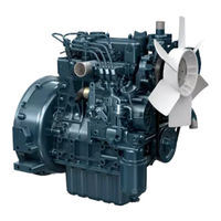
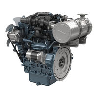
- V3300-E2B
- Workshop manual
-
Contents
-
Table of Contents
-
Troubleshooting
-
Bookmarks
Quick Links
WORKSHOP MANUAL
DIESEL ENGINE
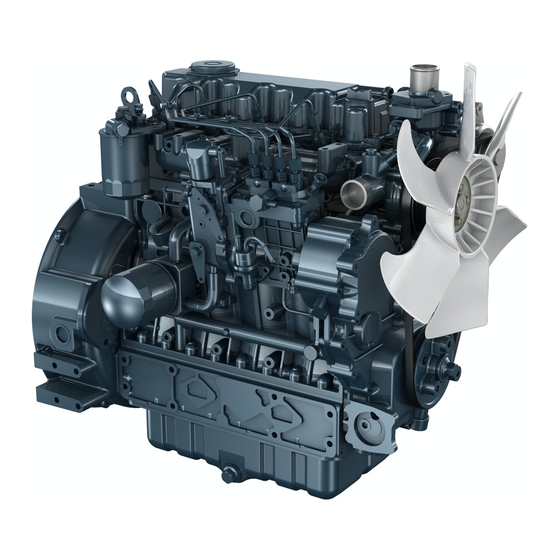
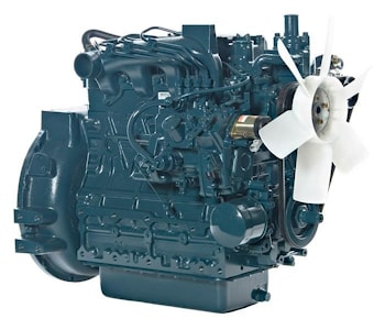
V3300-E2B,V3300-T-E2B
KiSC issued 06, 2006 A
Related Manuals for Kubota V3300-E2B
Summary of Contents for Kubota V3300-E2B
-
Page 1
WORKSHOP MANUAL DIESEL ENGINE V3300-E2B,V3300-T-E2B KiSC issued 06, 2006 A… -
Page 2
TO THE READER This Workshop Manual has been prepared to provide servicing personnel with information on the mechanism, service and maintenance of V3300-E2B, V3300-T-E2B. It is divided into three parts, “General”, “Mechanism” and “Servicing”. General Information on the engine identification, the general precautions, maintenance check list, check and maintenance and special tools are described. -
Page 3
V3300-E2B, V3300-T-E2B, WSM SAFETY INSTRUCTIONS SAFETY INSTRUCTIONS SAFETY FIRST This symbol, the industry’s “Safety Alert Symbol”, is used throughout this manual and on labels on the machine itself to warn of the possibility of personal injury. Read these instructions carefully. -
Page 4
V3300-E2B, V3300-T-E2B, WSM SAFETY INSTRUCTIONS SAFETY STARTING • Do not start the engine by shorting across starter terminals or bypassing the safety start switch. • Unauthorized modifications to the engine may impair the function and / or safety and affect engine life. -
Page 5
V3300-E2B, V3300-T-E2B, WSM SAFETY INSTRUCTIONS VENTILATE WORK AREA • If the engine must be running to do some work, make sure the area is well ventilated. Never run the engine in a closed area. The exhaust gas contains poisonous carbon monoxide. -
Page 6
V3300-E2B, V3300-T-E2B, WSM SPECIFICATIONS SPECIFICATIONS Model V3300-E2B V3300-T-E2B Number of Cylinder Type Vertical, water-cooled, 4-cycle diesel engine Bore × Stroke 98 × 110 mm (3.86 × 4.33 in.) Total Displacement 3318 cm (202.48 cu.in.) 44.1 kW / 2600 min (rpm) 53.8 kW / 2600 min… -
Page 7
V3300-E2B, V3300-T-E2B, WSM PERFORMANCE CURVES PERFORMANCE CURVES (1) Brake Horsepower (4) Torque (7) Net Continuous Torque (10) Net Continuous B.H.P. (2) Engine Speed (5) Gross Intermittent Torque (8) Gross Intermittent B.H.P. (11) B.S.F.C. (Net Intermittent) (3) B.S.F.C. (6) Net Intermittent Torque (9) Net Intermittent B.H.P. -
Page 8
V3300-E2B, V3300-T-E2B, WSM PERFORMANCE CURVES (1) Brake Horsepower (4) Torque (7) Net Continuous Torque (10) Net Continuous B.H.P. (2) Engine Speed (5) Gross Intermittent Torque (8) Gross Intermittent B.H.P. (11) B.S.F.C. (Net Intermittent) (3) B.S.F.C. (6) Net Intermittent Torque (9) Net Intermittent B.H.P. -
Page 9
V3300-E2B, V3300-T-E2B, WSM DIMENSIONS DIMENSIONS KiSC issued 06, 2006 A… -
Page 10: Table Of Contents
GENERAL CONTENTS 1. ENGINE IDENTIFICATION …………….G-1 [1] MODEL NAME AND ENGINE SERIAL NUMBER …….. G-1 [2] E2B ENGINE………………… G-1 [3] CYLINDER NUMBER …………….G-2 2. GENERAL PRECAUTIONS …………….G-3 3. MAINTENANCE CHECK LIST …………… G-4 4. CHECK AND MAINTENANCE …………… G-6 [1] DAILY CHECK POINTS…………….
-
Page 11: Engine Identification
V3300-E2B, V3300-T-E2B, WSM G GENERAL 1. ENGINE IDENTIFICATION [1] MODEL NAME AND ENGINE SERIAL NUMBER When contacting the manufacture, always specify your engine model name and serial number. The engine model and its serial number need to be identified before the engine can be serviced or parts replaced.
-
Page 12: E2B Engine
Phase 2 requirements, we have adopted E2B as a new model name for the engines conforming Tier 2 / Phase 2 regulations. In the after-sale services for V3300-E2B and V3300-T-E2B series engines, only use the dedicated parts for E2B models and carry out the maintenance services accordingly.
-
Page 13: General Precautions
Screws, bolts and nuts should be replaced in their original position to prevent reassembly errors. • When special tools are required, use KUBOTA genuine special tools. Special tools which are not frequently used should be made according to the drawings provided.
-
Page 14: Maintenance Check List
*Replacing intake air line Replacing battery * The items listed above (* marked) are registered as emission related critical parts by KUBOTA in the U.S.EPA nonroad emission regulation. As the engine owner, you are responsible for the performance of the required maintenance on the engine according to the above instruction.
-
Page 15
V3300-E2B, V3300-T-E2B, WSM G GENERAL CAUTION • When changing or inspecting, be sure to level and stop the engine. NOTE Lubricating Oil With the emission control now in effect, the CF-4 and CG-4 lubricating oils have been developed for use of a low- sulfur fuel on-road vehicle engines. -
Page 16: Check And Maintenance
V3300-E2B, V3300-T-E2B, WSM G GENERAL 4. CHECK AND MAINTENANCE [1] DAILY CHECK POINTS Checking Engine Oil Level 1. Level the engine. 2. To check the oil level, draw out the dipstick (1), wipe it clean, reinsert it, and draw it out again.
-
Page 17
V3300-E2B, V3300-T-E2B, WSM G GENERAL Checking and Replenish Coolant 1. Without recovery tank : Remove the radiator cap (1) and check to see that the coolant level is just below the port. With recovery tank (2) : Check to see that the coolant level lies between FULL (A) and LOW (B). -
Page 18: Check Points Of Initial 50 Hours
V3300-E2B, V3300-T-E2B, WSM G GENERAL [2] CHECK POINTS OF INITIAL 50 HOURS Changing Engine Oil CAUTION • Be sure to stop engine before changing engine oil. 1. Start and warm up the engine for approx. 5 minutes. 2. Place an oil pan underneath the engine.
-
Page 19: Check Point Of Every 50 Hours
V3300-E2B, V3300-T-E2B, WSM G GENERAL Fan Belt Tension 1. Measure the deflection (A), depressing the belt halfway between the fan drive pulley and alternator pulley at specified force 98 N (10 kgf, 22 lbs). 2. If the measurement is not within the factory specifications, loosen the alternator mounting screws and relocate the alternator to adjust.
-
Page 20: Check Points Of Every 250 Hours
V3300-E2B, V3300-T-E2B, WSM G GENERAL [4] CHECK POINTS OF EVERY 250 HOURS Fan Belt Tension 1. Measure the deflection (A), depressing the belt halfway between the fan drive pulley and alternator pulley at specified force 98 N (10 kgf, 22 lbs).
-
Page 21
V3300-E2B, V3300-T-E2B, WSM G GENERAL Cleaning Fuel Filter (Element Type only) 1. Close the fuel cock (3). 2. Unscrew the retaining ring (6) and remove the filter cup (5), and rinse the inside with kerosene. 3. Take out the element (4) and dip it in the kerosene to rinse. -
Page 22: Check Points Of Every 500 Hours
V3300-E2B, V3300-T-E2B, WSM G GENERAL Checking Battery Electrolyte Level 1. Check the battery electrolyte level. 2. If the level is below than lower level line (2), and the distilled water to pour level of each cell. (1) Upper Level Line…
-
Page 23
V3300-E2B, V3300-T-E2B, WSM G GENERAL Replacing Fan Belt 1. Remove the alternator. 2. Remove the fan belt (1). 3. Replace new fan belt. 4. Install the alternator. 5. Check the fan belt tension. 10.0 to 12.0 mm / 98 N Deflection (A) Factory spec. -
Page 24
V3300-E2B, V3300-T-E2B, WSM G GENERAL Anti-Freeze • There are two types of anti-freeze available: use the permanent type (PT) for this engine. • Before adding anti-freeze for the first time, clean the radiator interior by pouring fresh, soft water and draining it a few times. -
Page 25: Check Point Of Every 1000 Hours
V3300-E2B, V3300-T-E2B, WSM G GENERAL [6] CHECK POINT OF EVERY 1000 HOURS Checking Valve Clearance IMPORTANT • Valve clearance must be checked and adjusted when engine is cold. 1. Remove the head cover. 2. Align the 1TC mark of flywheel and the convex of flywheel housing timing windows so that the first piston (gear case side) comes to the compression top dead center.
-
Page 26: Check Points Of Every 1 Or 2 Months
V3300-E2B, V3300-T-E2B, WSM G GENERAL [7] CHECK POINTS OF EVERY 1 OR 2 MONTHS Recharging CAUTION • When the battery is being activated, hydrogen and oxygen gases in the battery are extremely explosive. Keep open sparks and flames away from the battery at all times, especially when charging the battery.
-
Page 27
V3300-E2B, V3300-T-E2B, WSM G GENERAL Battery Specific Gravity 1. Check the specific gravity of the electrolyte in each cell with a hydrometer. 2. When the electrolyte temperature differs from that at which the hydrometer was calibrated, correct the specific gravity reading following the formula mentioned in (Reference). -
Page 28: Check Points Of Every 1500 Hours
V3300-E2B, V3300-T-E2B, WSM G GENERAL [8] CHECK POINTS OF EVERY 1500 HOURS CAUTION • Check the injection pressure and condition after confirming that there is nobody standing in the direction the fume goes. • If the fume from the nozzle directly contacts the human body, cells may be destroyed and blood poisoning may be caused.
-
Page 29
V3300-E2B, V3300-T-E2B, WSM G GENERAL Nozzle Holder 1. Secure the nozzle retaining nut (7) with a vise. 2. Remove the nozzle holder (1), and take out parts inside. (When reassembling) • Assemble the nozzle in clean fuel oil. • Install the push rod (4), noting its direction. -
Page 30: Check Points Of Every 3000 Hours
V3300-E2B, V3300-T-E2B, WSM G GENERAL [9] CHECK POINTS OF EVERY 3000 HOURS Checking Turbocharger (Turbine Side) 1. Check the exhaust port (3) and inlet port (5) side of turbine housing (1) to see if there is no exhaust gas leak.
-
Page 31
V3300-E2B, V3300-T-E2B, WSM G GENERAL Injection Timing 1. Make sure of matching the injection timing align mark (1) of the injection pump unit and the plate (gearcase), as shown in the illustration. 2. Remove the injection pipes. 3. Remove the stop solenoid. -
Page 32
5. Set the speed control lever to the maximum speed position. 6. Run the starter to increase the pressure. 7. If the pressure can not reach the allowable limit, replace the pump with new one or repair with a Kubota-authorized pump service shop. (Fuel Tightness of Delivery Valve) 1. -
Page 33: Check Points Of Every 1 Year
V3300-E2B, V3300-T-E2B, WSM G GENERAL [10] CHECK POINTS OF EVERY 1 YEAR Changing Engine Oil CAUTION • Be sure to stop engine before changing engine oil. 1. Start and warm up the engine for approx. 5 minutes. 2. Place an oil pan underneath the engine.
-
Page 34: Check Points Of Every 2 Years
V3300-E2B, V3300-T-E2B, WSM G GENERAL [11] CHECK POINTS OF EVERY 2 YEARS Replacing Fan Belt 1. Remove the alternator. 2. Remove the fan belt (1). 3. Replace new fan belt. 4. Install the alternator. 5. Check the fan belt tension.
-
Page 35
V3300-E2B, V3300-T-E2B, WSM G GENERAL Changing Radiator Coolant (L.L.C.) (Continued) (Anti-freeze) • There are two types of anti-freeze available: use the permanent type (PT) for this engine. • Before adding anti-freeze for the first time, clean the radiator interior by pouring fresh, soft water and draining it a few times. -
Page 36
V3300-E2B, V3300-T-E2B, WSM G GENERAL Replacing Fuel Hose and Clamp Bands 1. Loosen the clamp (2) and remove the fuel hose (3). 2. Replace new fuel hose (3) and new clamp (2). 3. Tighten the clamp (2). CAUTION • Stop the engine when attempting the check and change prescribed above. -
Page 37: Special Tools
V3300-E2B, V3300-T-E2B, WSM G GENERAL 5. SPECIAL TOOLS Diesel Engine Compression Tester Code No: 07909-30208 (Assembly) 07909-31251 (G) 07909-30934 (A to F) 07909-31271 (I) 07909-31211 (E and F) 07909-31281 (J) 07909-31231 (H) Application: Use to measure diesel engine compression and diagnosis of need for major overhaul.
-
Page 38
V3300-E2B, V3300-T-E2B, WSM G GENERAL NOTE • The following special tools are not provided, so make them referring to the figure. Injection Pump Pressure Tester Application: Use to check fuel tightness of injection pumps. Pressure gauge full scale : More than 29.4 MPa… -
Page 39
V3300-E2B, V3300-T-E2B, WSM G GENERAL Small End Bushing Replacing Tool Application: Use to press out and to press fit the small end bushing. [Press out] 157 mm (6.181 in.) 14.5 mm (0.571 in.) 120 mm (4.7244 in.) 30.0 mm dia. (1.1811 in. dia.) 32.95 mm dia. -
Page 40
V3300-E2B, V3300-T-E2B, WSM G GENERAL Gear Case Oil Seal Replacing Tool Application: Use to press fit the oil seal. 148.8 mm (5.8582 in.) 50 mm (1.9685 in.) 18.8 mm (0.7401 in.) 13.7 to 13.9 mm (0.5394 to 0.5472 in.) 11 mm (0.433 in.) 18 mm dia. -
Page 41
V3300-E2B, V3300-T-E2B, WSM G GENERAL Valve Guide Replacing Tool Application: Use to press out and press fit the valve guide. Intake valve guide 225 mm (8.86 in.) 70 mm (2.76 in.) 45 mm (1.77 in.) 20 mm dia. (0.79 in dia.) 11.7 to 11.9 mm dia. -
Page 42
V3300-E2B, V3300-T-E2B, WSM G GENERAL Auxiliary Socket for Fixing Crankshaft Sleeve Application: Use to fix the crankshaft sleeve of the diesel engine. Rmax = 12.5 S 94.5 to 95.0 mm dia. (3.7205 to 3.7402 in. dia.) 40 mm dia. (1.5748 in. dia.) 30 mm dia. -
Page 43
V3300-E2B, V3300-T-E2B, WSM G GENERAL Balancer Bushing Replacing Tool 1 Components Parts 1) Shaft 498 mm (19.61 in.) 318.8 to 319.2 mm (12.5512 to 12.5669 in.) 102.8 to 103.2 mm (4.0472 to 4.0630 in.) 60 mm (2.36 in.) 8 mm (0.31 in.) 5 mm (0.20 in.) -
Page 44
V3300-E2B, V3300-T-E2B, WSM G GENERAL 3) Piece 2 Chamfer 0.1 mm (0.004 in.) 1 mm (0.04 in.) Chamfer 1mm (0.04 in.) 54.3 to 54.4 mm dia. (2.1378 to 2.1417 in. dia.) 34.025 to 34.05 mm dia. (1.3396 to 1.3406 in. dia.) 48.5 mm dia. -
Page 45
V3300-E2B, V3300-T-E2B, WSM G GENERAL Balancer Replacing Tools 3, 4, 5 Application: Use to press fit the bushing. NOTE • This special tool is not provided, so make it referring to the figure. Name of Part Q’ty. Bracket Flange Nut… -
Page 46
V3300-E2B, V3300-T-E2B, WSM G GENERAL 2) Shaft 44 mm dia. (1.73 in. dia.) 12 mm (0.47 in.) Chamfer 1 mm (0.04 in.) 3 mm (0.12 in.) 3 mm (0.12 in.) 30 mm (1.18 in.) 38 mm (1.50 in.) 35 mm (1.38 in.) M12 ×… -
Page 47
V3300-E2B, V3300-T-E2B, WSM G GENERAL 4) Joint 1 M12 × P1.25 Chamfer 1 mm (0.04 in.) 30 mm dia. (1.18 in. dia.) 13 mm dia. (0.51 in. dia.) Chamfer 3 mm (0.12 in.) 3 mm (0.12 in.) 45 mm (1.77 in.) 75 mm (2.95 in.) -
Page 48
V3300-E2B, V3300-T-E2B, WSM G GENERAL 7) Piece 3 26 mm (1.02 in.) 18 mm (0.71 in.) 16.5 to 17.0 mm (0.6496 to 0.6693 in.) 1.5 mm (0.06 in.) 53.0 to 53.2 mm dia. (2.0866 to 2.0945 in dia.) 49.55 to 49.75 mm dia. (1.9508 to 1.9587 in dia.) 16 mm (0.63 in.) -
Page 49
V3300-E2B, V3300-T-E2B, WSM G GENERAL Engine Stand Application: Use to support engine. 480 mm (18.90 in.) 50 mm (1.97 in.) 108.5 mm (4.272 in.) 262.5 mm (10.33 in.) 12.5 mm (0.492 in.) 237.5 mm (9.350 in.) 142.5 mm (5.610 in.) 95 mm (3.74 in.) -
Page 50
V3300-E2B, V3300-T-E2B, WSM G GENERAL Jig for Governor Connecting Rod Application: Use for connecting the governor connecting rod to the rack pin of the fuel injection pump assembly. 1 mm radius (0.0394 in. radius) Chamfer 0.2 mm (0.0079 in.) Chamfer 2 mm (0.0787 in.) 35 mm dia. -
Page 51
MECHANISM CONTENTS 1. FEATURE ………………….M-1 2. ENGINE BODY ………………..M-2 [1] CYLINDER BLOCK………………. M-2 [2] HALF-FLOATING HEAD COVER …………M-2 [3] CYLINDER HEAD ………………M-3 [4] PISTON AND PISTON RINGS …………… M-3 [5] BUILT-IN DYNAMIC BALANCER (BALANCER MODEL ONLY)..M-4 3. -
Page 52: Feature
E-TVCS VERSION-II. Thus, this engine achieves high combustion efficiency and complies with various regulations of exhaust gas. Based upon the conventional model, Kubota developed a unique governor system and various new mechanisms which reduces exhaust emission, noise and vibration and realize durability and high torque.
-
Page 53: Engine Body
V3300-E2B, V3300-T-E2B, WSM DIESEL ENGINE 2. ENGINE BODY [1] CYLINDER BLOCK This engine employs separate type crankcases — the crankcase 1 (1) with combustion part and the crankcase 2 (2) which supports the crankcase 1 (1) and reduces noise. Since it is a hanger type, you can easily assemble / disassemble it.
-
Page 54: Cylinder Head
It also employs Kubota’s unique combustion chamber with multiple injection grooves. Besides the conventional cross port system, it employs the forced cooling method between valves to eliminate heat distortion, thus enabling durable and reliable configuration.
-
Page 55: Built-In Dynamic Balancer (Balancer Model Only
V3300-E2B, V3300-T-E2B, WSM DIESEL ENGINE [5] BUILT-IN DYNAMIC BALANCER (BALANCER MODEL ONLY) Engine are sure to vibrate by piston’s reciprocation. Theoretically, three-cylinder engines are much less prone to cause vibration than four-cylinder ones (second inertia, etc.). However, any engine has many moving parts in addition to its pistons and cannot be completely free from vibration.
-
Page 56: Lubricating System
V3300-E2B, V3300-T-E2B, WSM DIESEL ENGINE 3. LUBRICATING SYSTEM [1] OIL COOLER V3 series engine has a water-cooled oil cooler that not only cools hot oil, but also warms the cool engine oil shoftly after start up. As shown in the figure, the oil flows inside the…
-
Page 57: Cooling System
V3300-E2B, V3300-T-E2B, WSM DIESEL ENGINE 4. COOLING SYSTEM [1] THERMOSTAT Conventional thermostatically-controlled valves (outlet water temperature control type) open against the flow of coolant. In this design, the pressure (steam pressure + water pump’s discharge pressure) affects the open/close performance of such valve. In other words,…
-
Page 58: Bottom Bypass System
V3300-E2B, V3300-T-E2B, WSM DIESEL ENGINE [2] BOTTOM BYPASS SYSTEM Bottom bypass system is introduced in V3 series for improving the cooling performance of the radiator. While the temperature of coolant in the engine is low, the thermostat is held closed and the coolant is allowed to flow through the bypass pipe and to circulate in the engine.
-
Page 59: Fuel System
DIESEL ENGINE 5. FUEL SYSTEM [1] GOVERNOR The engine employs the separated fuel injection pump in combination with Kubota’s own small multi- function mechanical governor, which enable more dependability. It also employs the torque limiting mechanism to control the maximum peak torque so that it complies with the regulations of exhaust gas.
-
Page 60
V3300-E2B, V3300-T-E2B, WSM DIESEL ENGINE At Idling Turn the speed control lever (6) clockwise to idle the engine. It tensions the governor spring (3) to pull the fork lever 2 (1). When the fork lever 2 is pulled, it moves the torque spring pin (7) and the fork lever 1 (5) in the direction of the arrow A to restrain the weight. -
Page 61
V3300-E2B, V3300-T-E2B, WSM DIESEL ENGINE To stop engine When the stop solenoid is turned off, the spring tension of the solenoid is released, the rod extrudes and the stop lever moves the control rack in the direction of the arrow B which stops the engine. -
Page 62: Turbocharger System
V3300-E2B, V3300-T-E2B, WSM DIESEL ENGINE 6. TURBOCHARGER SYSTEM [1] BOOST COMPENSATOR The boost compensator is controlled by the boost pressure of the control mechanism which controls transient smoke caused by oversupply of fuel when the engine starts and accelerates. When the boost pressure is lower than working pressure of the boost actuator (1), it prevents oversupply of fuel to reduce transient smoke.
-
Page 63
SERVICING CONTENTS 1. TROUBLESHOOTING ………………S-1 2. SERVICING SPECIFICATIONS …………..S-5 3. TIGHTENING TORQUES …………….S-12 [1] TIGHTENING TORQUES FOR GENERAL USE SCREWS, BOLTS AND NUTS………………..S-12 [2] TIGHTENING TORQUES FOR SPECIAL USE SCREWS, BOLTS AND NUTS………………..S-13 4. CHECKING, DISASSEMBLING AND SERVICING……..S-15 [1] CHECKING AND ADJUSTING ……………S-15 (1) Engine Body………………S-15 (2) Lubricating System …………….S-17 (3) Cooling System……………….S-17… -
Page 64: Troubleshooting
V3300-E2B, V3300-T-E2B, WSM DIESEL ENGINE 1. TROUBLESHOOTING Reference Symptom Probable Cause Solution Page Engine Does Not No fuel Replenish fuel Start Air in the fuel system Vent air Water in the fuel system Change fuel and – repair or replace fuel…
-
Page 65
V3300-E2B, V3300-T-E2B, WSM DIESEL ENGINE Reference Symptom Probable Cause Solution Page Engine Revolution Is Fuel filter clogged or dirty Replace G-11, 12 Not Smooth Air cleaner clogged Clean or replace G-10, 23 Fuel leak due to loose injection pipe retaining nut… -
Page 66
V3300-E2B, V3300-T-E2B, WSM DIESEL ENGINE Reference Symptom Probable Cause Solution Page Deficient Output Incorrect injection timing Adjust S-20 Engine’s moving parts seem to be seizing Repair or replace – Injection pump malfunctioning Repair or replace S-21, 42 Deficient nozzle injection… -
Page 67
V3300-E2B, V3300-T-E2B, WSM DIESEL ENGINE Reference Symptom Probable Cause Solution Page High Oil Pressure Different type of oil Use specified type of 4, G-11 Relief valve defective Replace S-46 Engine Overheated Engine oil insufficient Replenish G-6, 8 Fan belt broken or elongated… -
Page 68: Servicing Specifications
V3300-E2B, V3300-T-E2B, WSM DIESEL ENGINE 2. SERVICING SPECIFICATIONS ENGINE BODY Item Factory Specification Allowable Limit Cylinder Head Surface Flatness – 0.05 mm 0.0020 in. Top Clearance V3300-E2B 0.72 to 0.90 mm – 0.0283 to 0.0354 in. V3300-T-E2B 0.92 to 1.10 mm –…
-
Page 69
V3300-E2B, V3300-T-E2B, WSM DIESEL ENGINE ENGINE BODY (Continued) Item Factory Specification Allowable Limit Valve Stem to Valve Guide Clearance (Intake) 0.055 to 0.085 mm 0.1 mm 0.0022 to 0.0033 in. 0.0039 in. Valve Stem O.D. (Intake) 6.960 to 6.975 mm –… -
Page 70
V3300-E2B, V3300-T-E2B, WSM DIESEL ENGINE ENGINE BODY (Continued) Item Factory Specification Allowable Limit Rocker Arm Shaft to Rocker Arm Clearance 0.016 to 0.045 mm 0.15 mm 0.0006 to 0.0018 in. 0.0059 in. Rocker Arm Shaft O.D. 15.973 to 15.984 mm –… -
Page 71
V3300-E2B, V3300-T-E2B, WSM DIESEL ENGINE ENGINE BODY (Continued) Item Factory Specification Allowable Limit Timing Gear Idle Gear 1 to Crank Gear Backlash 0.049 to 0.193 mm 0.22 mm 0.0019 to 0.0076 in. 0.0087 in. Idle Gear 1 to Cam Gear Backlash 0.049 to 0.189 mm… -
Page 72
V3300-E2B, V3300-T-E2B, WSM DIESEL ENGINE ENGINE BODY (Continued) Item Factory Specification Allowable Limit Piston Ring Gap Top Ring 0.30 to 0.45 mm 1.25 mm 0.0118 to 0.0177 in. 0.0492 in. Second Ring 0.30 to 0.45 mm 1.25 mm 0.0118 to 0.0177 in. -
Page 73
V3300-E2B, V3300-T-E2B, WSM DIESEL ENGINE LUBRICATING SYSTEM Item Factory Specification Allowable Limit Engine Oil Pressure At Idle Speed – 49 kPa 0.5 kgf/cm 7 psi At Rated Speed 196 to 392 kPa 147.1 kPa 2.0 to 4.0 kgf/cm 1.5 kgf/cm 28 to 57 psi 21.3 psi… -
Page 74
V3300-E2B, V3300-T-E2B, WSM DIESEL ENGINE FUEL SYSTEM Item Factory Specification Allowable Limit Injection Timing V3300-E2B 0.19 to 0.23 rad – (11 to 13 °) before T.D.C. V3300-T-E2B 0.11 to 0.14 rad – (6 to 8 °) before T.D.C. Pump Element Fuel Tightness –… -
Page 75: Tightening Torques
V3300-E2B, V3300-T-E2B, WSM DIESEL ENGINE 3. TIGHTENING TORQUES Screws, bolts and nuts must be tightened to the specified torque using a torque wrench, several screws, bolts and nuts such as those used on the cylinder head must be tightened in proper sequence and the proper torque.
-
Page 76: Tightening Torques For Special Use Screws, Bolts And Nuts
V3300-E2B, V3300-T-E2B, WSM DIESEL ENGINE [2] TIGHTENING TORQUES FOR SPECIAL USE SCREWS, BOLTS AND NUTS NOTE • For “*” marked screws, bolts and nuts on the table, apply engine oil to their threads and seats before tightening. • The letter “M” in Size x Pitch means that the screw, bolt or nut dimension stands for metric. The size is the nominal outside diameter in mm of the threads.
-
Page 77
V3300-E2B, V3300-T-E2B, WSM DIESEL ENGINE Item Size x Pitch N·m kgf·m ft-lbs Governor housing mounting screw M6 x 1.0 9.8 to 11.3 1.00 to 1.15 7.23 to 8.32 Anti-rotation nut M5 x 0.8 2.8 to 4.0 0.29 to 0.41 2.1 to 3.0 Balancer shaft set screw M8 x 1.25… -
Page 78: Checking, Disassembling And Servicing
V3300-E2B, V3300-T-E2B, WSM DIESEL ENGINE 4. CHECKING, DISASSEMBLING AND SERVICING [1] CHECKING AND ADJUSTING (1) Engine Body Compression Pressure 1. After warming up the engine, stop it and remove the air cleaner, the muffler and all nozzle holders. 2. Install a compression tester (Code No: 07909-30208) for diesel engines to nozzle holder hole.
-
Page 79
V3300-E2B, V3300-T-E2B, WSM DIESEL ENGINE Checking Valve Clearance IMPORTANT • Valve clearance must be checked and adjusted when engine is cold. 1. Remove the head cover. 2. Align the 1TC mark of flywheel and the convex of flywheel housing timing windows so that the first piston (gear case side) comes to the compression top dead center. -
Page 80
V3300-E2B, V3300-T-E2B, WSM DIESEL ENGINE (2) Lubricating System Engine Oil Pressure 1. Remove the oil switch and set a pressure tester (Code No. 07916-32032). 2. Start the engine. After warming up, measure the oil pressure of both idling and rated speeds. -
Page 81
V3300-E2B, V3300-T-E2B, WSM DIESEL ENGINE Fan Belt Damage and Wear 1. Check the fan belt for damage. 2. If the fan belt is damaged, replace it. 3. Check if the fan belt is worn and sunk in the pulley groove. -
Page 82
V3300-E2B, V3300-T-E2B, WSM DIESEL ENGINE Thermostat Valve Opening Temperature 1. Push down the thermostat valve and insert a string between the valve and the valve seat. 2. Place the thermostat and a thermostat in a container with water and gradually heat the water. -
Page 83
V3300-E2B, V3300-T-E2B, WSM DIESEL ENGINE (4) Fuel System Injection Timing 1. Make sure of matching the injection timing align mark (1) of the injection pump unit and the plate (gearcase), as shown in the illustration. 2. Remove the injection pipes. -
Page 84
5. Set the speed control lever to the maximum speed position. 6. Run the starter to increase the pressure. 7. If the pressure can not reach the allowable limit, replace the pump with new one or repair with a Kubota-authorized pump service shop. 13.73 MPa… -
Page 85
V3300-E2B, V3300-T-E2B, WSM DIESEL ENGINE CAUTION • Check the nozzle injection pressure and condition after confirming that there is nobody standing in the direction the fume goes. • If the fume from the nozzle directly contacts the human body, cells may be destroyed and blood poisoning may be caused. -
Page 86: Electrical System
V3300-E2B, V3300-T-E2B, WSM DIESEL ENGINE Nozzle Holder 1. Secure the nozzle retaining nut (7) with a vise. 2. Remove the nozzle holder (1), and take out parts inside. (When reassembling) • Assemble the nozzle in clean fuel oil. • Install the push rod (4), noting its direction.
-
Page 87
V3300-E2B, V3300-T-E2B, WSM DIESEL ENGINE Battery Specific Gravity 1. Check the specific gravity of the electrolyte in each cell with a hydrometer. 2. When the electrolyte temperature differs from that at which the hydrometer was calibrated, correct the specific gravity reading following the formula mentioned in (Reference). -
Page 88
V3300-E2B, V3300-T-E2B, WSM DIESEL ENGINE Motor Test CAUTION • Secure the starter to prevent it from jumping up and down while testing the motor. 1. Disconnect the battery negative cable from the battery. 2. Disconnect the battery positive cable from the battery. -
Page 89
V3300-E2B, V3300-T-E2B, WSM DIESEL ENGINE Alternator on Unit Test (Before testing) • Before alternator on unit test, check the battery terminal connections, circuit connection, fan belt tension, charging indicator lamp, fuses on the circuit, and abnormal noise from the alternator. -
Page 90: Turbocharger
V3300-E2B, V3300-T-E2B, WSM DIESEL ENGINE Engine Stop Solenoid 1. Remove the engine stop solenoid from the engine. 2. Connect the jumper leads from the pulling coil P terminal to the switch (3), and from switch (3) to the battery positive terminal.
-
Page 91: Disassembling And Assembling
V3300-E2B, V3300-T-E2B, WSM DIESEL ENGINE [2] DISASSEMBLING AND ASSEMBLING (1) Draining Oil and Coolant Draining Engine Oil 1. Start and warm up the engine for approx. 5 minutes. 2. Place an oil pan underneath the engine. 3. Remove the drain plug (1) to drain oil.
-
Page 92
V3300-E2B, V3300-T-E2B, WSM DIESEL ENGINE CAUTION • While the engine is running and or just after it stops, the turbocharger is hot, be careful not to touch the turbocharger. NOTE • When detaching and attaching the turbocharger assembly, be very careful not to allow dust, dirt and other foreign matter in the oil pipes. -
Page 93: Cylinder Head And Valves
V3300-E2B, V3300-T-E2B, WSM DIESEL ENGINE (3) Cylinder Head and Valves Cylinder Head Cover and Nozzle Holder 1. Remove the injection pipes (3) and overflow pipes (2). 2. Remove the glow plugs (1). 3. Remove the nozzle holder assembly (4) and copper gaskets (5).
-
Page 94
V3300-E2B, V3300-T-E2B, WSM DIESEL ENGINE Rocker Arm and Push Rod 1. Remove the rocker arm (3) as a unit. 2. Remove the push rods (1). 3. Remove the bridge arm (4). (When reassembling) • When putting the push rods onto the tappets (2), check to see if their ends are properly engaged with the grooves. -
Page 95
V3300-E2B, V3300-T-E2B, WSM DIESEL ENGINE Cylinder Head and Tappet 1. Loosen the pipe band, and remove the water return pipe (1). 2. Disconnect the fuel pipe (2) first and then the fuel filter (3). 3. Remove the IN. / EX. Manifold. -
Page 96
V3300-E2B, V3300-T-E2B, WSM DIESEL ENGINE Selecting Cylinder Head Gasket Replacing the Cylinder Head Gasket 1. Make sure the notch mark (a), (b) or (c) of cylinder head gasket (1) in advance. 2. Replace the same notch mark (a), (b) or (c) as the original cylinder head gasket (1). -
Page 97: Thermostat
V3300-E2B, V3300-T-E2B, WSM DIESEL ENGINE (4) Thermostat Thermostat Assembly 1. Remove the thermostat cover mounting screws, and remove the thermostat cover (1). 2. Remove the thermostat assembly (3). (When reassembling) • Apply a liquid gasket (Three Bond 1215 or equivalent) only at the thermostat cover side of the gasket (2).
-
Page 98: Injection Pump Unit
V3300-E2B, V3300-T-E2B, WSM DIESEL ENGINE (6) Injection Pump Unit Injection Pump Unit (Removing the fuel injection pump unit) 1. Detach the gear cover for the fuel injection pump unit from the gearcase. 2. Place the piston of the 4th cylinder at the top dead center in the compression stroke.
-
Page 99
V3300-E2B, V3300-T-E2B, WSM DIESEL ENGINE Injection Pump Unit (Continued) (Reassembling the fuel injection pump unit) 1. Place the piston of the 4th cylinder at the top dead center in the compression stroke. Fix the flywheel with the flywheel stopper. 2. Place the injection pump gear (1) back into the gear case position. -
Page 100
V3300-E2B, V3300-T-E2B, WSM DIESEL ENGINE Governor Housing Assembly 1. Remove the injection pump unit from the engine. (See the “Injection Pump Unit”.) 2. Remove the governor lubricating pipe (3). 3. Remove the stop solenoid (1). 4. Detach the sight cover (2) from the injection pump unit. -
Page 101
V3300-E2B, V3300-T-E2B, WSM DIESEL ENGINE Governor Fork Lever Assembly 1. Pull off the governor fork lever shaft (1) with the extra bolt (Dia : 4 mm, Pitch : 0.7 mm, Length : more than 25 mm) (2). 2. Unhook the governor spring (3) at the governor fork lever (4) side. -
Page 102
V3300-E2B, V3300-T-E2B, WSM DIESEL ENGINE Governor Lever 1. Remove the speed control lever (1) and the return spring (2). 2. Remove the governor lever assembly (4) from the governor housing. 3. Remove the start spring (5) and the stop spring (3). -
Page 103
V3300-E2B, V3300-T-E2B, WSM DIESEL ENGINE Fuel Camshaft and Governor Weight 1. Separate the governor housing assembly from the injection pump unit. (See the “Injection Pump Unit”.) 2. Remove the governor sleeve (1). 3. Remove the injection pump assembly (2). 4. Remove the cover (3). -
Page 104
V3300-E2B, V3300-T-E2B, WSM DIESEL ENGINE Fuel Camshaft and Governor Weight (Continued) (When reassembling) • Fix the fuel camshaft with lock bolts as the key way of fuel camshaft (10) is upward. • Install the injection pump assembly to the injection pump housing. -
Page 105
V3300-E2B, V3300-T-E2B, WSM DIESEL ENGINE Replacing Injection Pump Assembly (If necessary) • The injection pump can be replaced with the crankshaft in whatever position. 1. Disconnect all injection pipes (1). 2. Disconnect the fuel pipe (6) and fuel overflow pipe (4). -
Page 106
V3300-E2B, V3300-T-E2B, WSM DIESEL ENGINE Installing Procedure of Injection Pump Assembly 1. Install the fuel injection pump assembly (1) in its unit (2), and hook the governor connecting rod to the rack pin of the fuel injection pump assembly. 2. Place the service jig (3) in the stop solenoid mounting hole of the fuel injection pump unit. -
Page 107
V3300-E2B, V3300-T-E2B, WSM DIESEL ENGINE Installing Procedure (Continued) 1. Move the stop lever (1) and visually check to see if the fuel injection pump control rack comes smoothly back to the start position by the counter force of the start spring. -
Page 108: Water Pump And Oil Cooler
V3300-E2B, V3300-T-E2B, WSM DIESEL ENGINE (7) Water Pump and Oil Cooler Water Pump 1. Remove the pipe band and the water pipe (1). 2. Remove the water pump (2). (When reassembling) • When mounting the water pump, take care not to forget mounting the O-ring and not to let it out of position.
-
Page 109: Gear Case And Timing Gears
V3300-E2B, V3300-T-E2B, WSM DIESEL ENGINE (8) Gear Case and Timing Gears Gear Case Cover 1. Remove the gear case cover. (When reassembling) • Confirm that the liquid gasket coating surface is free of water, dust and oil in order to maintain sealing effect.
-
Page 110
V3300-E2B, V3300-T-E2B, WSM DIESEL ENGINE Idle Gear 1 and Idle Gear 2 (for Balancer Model) 1. Remove the idle gear mounting screw (1). 2. Draw out the idle gear (2) and (3). (When reassembling) • When install the idle gear (2) and (3), be sure to place the 4th… -
Page 111: Piston And Connecting Rod
V3300-E2B, V3300-T-E2B, WSM DIESEL ENGINE Plate (Gear Case) 1. Remove the three plate mounting screws (1). Detach the plate (2). (When reassembling) • Apply Three Bond 1217D adhesive or equivalent over the shaded zones on both sides of the gasket that will be sandwiched between the crankcase and plate.
-
Page 112
V3300-E2B, V3300-T-E2B, WSM DIESEL ENGINE Connecting Rod Cap 1. Remove the connecting rod screws (1) from connecting rod cap. 2. Remove the connecting rod caps. (When reassembling) • Align the marks (a) with each other. (Face the marks toward the injection pump.) -
Page 113
V3300-E2B, V3300-T-E2B, WSM DIESEL ENGINE Piston Ring and Connecting Rod 1. Remove the piston rings using a piston ring tool. 2. Put the fan shaped concave (8) on the piston as shown in figure. 3. Remove the piston pin (7), and separate the connecting rod (6) from the piston (5). -
Page 114: Flywheel And Crankshaft
V3300-E2B, V3300-T-E2B, WSM DIESEL ENGINE (10) Flywheel and Crankshaft Flywheel 1. Install the stopper to the flywheel so that the flywheel does not turn. NOTE • Do not use an impact wrench. Serious damage will occur. 2. Detach the flywheel screws.
-
Page 115
V3300-E2B, V3300-T-E2B, WSM DIESEL ENGINE Flywheel Housing 1. Remove the flywheel housing. (When reassembling) • Tighten the flywheel housing mounting screws with even force on the diagonal line. • Make sure the crank cases 1 and 2 are clean. Install them in position, referring to the flywheel housing’s contoured face. -
Page 116
V3300-E2B, V3300-T-E2B, WSM DIESEL ENGINE Crankshaft 1. Remove the main bearing case. 2. Remove the crankshaft. (When reassembling) • Reassemble the main bearing case having the same number as the one engraved on the crankcase, and set the casting mark “F / W SIDE”… -
Page 117: Starter
V3300-E2B, V3300-T-E2B, WSM DIESEL ENGINE (11) Starter Disassembling Motor 1. Disconnect the solenoid switch (3). 2. Remove the 2 through screws (9) and the 2 brush holder lock screws. Take out the rear end frame (13) and the brush holder (12).
-
Page 118
V3300-E2B, V3300-T-E2B, WSM DIESEL ENGINE Rotor 1. Remove the 4 screws and detach the bearing retainer. 2. Temporarily install the nut on the pulley screw, and detach the rotor. W1074920 Brush 1. When the rotor is detached, the 2 brushes are found to stretch out of the shaft hole. -
Page 119: Servicing
V3300-E2B, V3300-T-E2B, WSM DIESEL ENGINE Bearing at Slip Ring Side 1. Lightly secure the rotor (1) with a vise to prevent damage, and remove the bearing (2) with a puller (3). (1) Rotor (3) Puller (2) Bearing W1019701 [3] SERVICING…
-
Page 120
V3300-E2B, V3300-T-E2B, WSM DIESEL ENGINE Cylinder Head Surface Flatness 1. Clean the cylinder head surface. 2. Place a straightedge on the cylinder head’s four sides (A), (B), (C) and (D) and two diagonal (E) and (F) as shown in the figure. -
Page 121
V3300-E2B, V3300-T-E2B, WSM DIESEL ENGINE Valve Recessing 1. Clean the cylinder head, the valve face and seat. 2. Insert the valve into the valve guide. 3. Measure the valve recessing with a depth gauge. 4. If the measurement exceeds the allowable limit, replace the valve. -
Page 122
V3300-E2B, V3300-T-E2B, WSM DIESEL ENGINE Clearance between Valve Stem and Valve Guide 1. Remove carbon from the valve guide section. 2. Measure the valve stem O.D. with an outside micrometer. 3. Measure the valve guide I.D. of the cylinder head at the most wear part as shown in the figure below with a small hole gauge. -
Page 123
V3300-E2B, V3300-T-E2B, WSM DIESEL ENGINE Correcting Valve and Valve Seat NOTE • Before correcting the valve and seat, check the valve stem and the I.D. of valve guide section, and repair them if necessary. • After correcting the valve seat, be sure to check the valve recessing. -
Page 124
V3300-E2B, V3300-T-E2B, WSM DIESEL ENGINE Free Length and Tilt of Valve Spring 1. Measure the free length (B) with vernier calipers. If the measurement is less than the allowable limit, replace it. 2. Put the spring on a surface plate, place a square on the side of the spring, and check to see if the entire side is contact with the square. -
Page 125
V3300-E2B, V3300-T-E2B, WSM DIESEL ENGINE Push Rod Alignment 1. Place the push rod on V blocks. 2. Measure the push rod alignment. 3. If the measurement exceeds the allowable limit, replace the push rod. 0.25 mm Push rod alignment Allowable limit 0.0098 in. -
Page 126: Timing Gears
V3300-E2B, V3300-T-E2B, WSM DIESEL ENGINE (2) Timing Gears Timing Gear Backlash 1. Set a dial indicator (lever type) with its tip on the gear tooth. 2. Move the gear to measure the backlash, holding its mating gear. 3. If the backlash exceeds the allowable limit, check the oil clearance of the shafts and the gear.
-
Page 127
V3300-E2B, V3300-T-E2B, WSM DIESEL ENGINE Camshaft Alignment 1. Support the camshaft with V block on the surface plate and set a dial indicator with its tip on the intermediate journal at right angle. 2. Rotate the camshaft on the V blocks and get the misalignment (half of the measurement). -
Page 128
V3300-E2B, V3300-T-E2B, WSM DIESEL ENGINE Oil Clearance between Idle Gear Shaft 1, 2 and Idle Gear 1, 2 Bushing 1. Measure the idle gear shaft O.D. with an outside micrometer. 2. Measure the idle gear bushings I.D. with an inside micrometer, and calculate the oil clearance. -
Page 129: Piston And Connecting Rod
V3300-E2B, V3300-T-E2B, WSM DIESEL ENGINE Oil Clearance of Balancer Shaft Journal 1. Measure the balancer shaft journal O.D. with an outside micrometer. 2. Measure the cylinder block bore I.D. (A), (B) for balancer shaft with an inside micrometer. 3. If the clearance exceeds the allowable limit, replace the balancer shaft.
-
Page 130
V3300-E2B, V3300-T-E2B, WSM DIESEL ENGINE Replacing Small End Bushing (When removing) 1. Press out the used bushing using a small end bushing replacing tool. (When installing) 1. Clean a new small end bushing and bore, and apply engine oil to them. -
Page 131: Crankshaft
V3300-E2B, V3300-T-E2B, WSM DIESEL ENGINE Clearance between Piston Ring and Groove 1. Remove carbon from the ring grooves. 2. Measure the clearance between the ring and the groove with a feeler gauge or depth gauge. 3. If the clearance exceeds allowable limit, replace the ring since compression leak and oil shortage result.
-
Page 132
V3300-E2B, V3300-T-E2B, WSM DIESEL ENGINE Crankshaft Alignment 1. Support the crankshaft with V block on the surface plate and set a dial indicator with its tip on the intermediate journal at right angle. 2. Rotate the crankshaft on the V block and get the misalignment (half of the measurement). -
Page 133
V3300-E2B, V3300-T-E2B, WSM DIESEL ENGINE Oil Clearance between Crankpin and Crankpin Bearing (Continued) IMPORTANT • STD size crankpin bearing. To replace it with a specific STD service part, make sure the crankpin bearing has the same ID color as the connecting rod. -
Page 134
V3300-E2B, V3300-T-E2B, WSM DIESEL ENGINE Oil Clearance between Crankshaft Journal and Crankshaft Bearing 1. Clean the crankshaft journal and crankshaft bearing. 2. Put a strip of press gauge on the center of the journal. IMPORTANT • Never insert the press gauge into the oil hole of the journal. -
Page 135: Cylinder
V3300-E2B, V3300-T-E2B, WSM DIESEL ENGINE (5) Cylinder Cylinder Wear 1. Measure the I.D. of the cylinder at the six positions (see figure) with a cylinder gauge to find the maximum and minimum I.D.’s. 2. Get the difference (Maximum wear) between the maximum and the minimum I.D.’s.
-
Page 136: Starter
V3300-E2B, V3300-T-E2B, WSM DIESEL ENGINE Clearance between Outer Rotor and Pump Body 1. Measure the clearance between the outer rotor and the pump body with a feeler gauge. 2. If the clearance exceeds the allowable limit, replace the oil pump rotor assembly.
-
Page 137
V3300-E2B, V3300-T-E2B, WSM DIESEL ENGINE Commutator and Mica 1. Check the contact face of the commutator for wear, and grind the commutator with emery paper if it is slightly worn. 2. Measure the commutator O.D. with an outside micrometer at several points. -
Page 138: Alternator
V3300-E2B, V3300-T-E2B, WSM DIESEL ENGINE Armature Coil 1. Check the continuity across the commutator and armature coil core with an ohmmeter. 2. If it conducts, replace the armature. 3. Check the continuity across the segments of the commutator with an ohmmeter.
-
Page 139
V3300-E2B, V3300-T-E2B, WSM DIESEL ENGINE Rotor 1. Measure the resistance across the slip rings with an ohmmeter. 2. If the resistance is not the factory specification, replace it. 3. Check the continuity across the slip and core with an ohmmeter. -
Page 140
EDITOR : KUBOTA FARM & INDUSTRIAL MACHINERY SERVICE, LTD. 64, ISHIZU-KITAMACHI, SAKAI-KU, SAKAI-CITY, OSAKA, 590-0823, JAPAN PHONE : ( 81 ) 72-241-1129 : ( 81 ) 72-245-2484 E-mail : ksos-pub@kubota.co.jp Printed in Japan 2005. 12, S, EI, EI, e Code No.9Y011-02912 KUBOTA Corporation 2004.
- Manuals
- Brands
- Kubota Manuals
- Engine
ManualsLib has more than 242 Kubota Engine manuals
Click on an alphabet below to see the full list of models starting with that letter:
0
1
9
B
D
E
F
G
R
S
V
W
Z
Popular manuals
330 pages
V3800-CR-TE4 Diagnosis Manual
203 pages
V3600-E3 Shop Manual
69 pages
Z402-EB-ONAN-1 Workshop Manual
143 pages
Z482-E2B Workshop Manual

278 pages
05 series Workshop Manual
124 pages
D1503-M-DI Workshop Manual
113 pages
V2003-T-B Workshop Manual
125 pages
05 Series Workshop Manual
38 pages
Z482-E Operator’s Manual
309 pages
D1803-CR-E4 Workshop Manual
242 pages
WG1605-E3 Diagnostic Manual
140 pages
V3300-E2B Workshop Manual
110 pages
D1102-B Workshop Manual

182 pages
D1503-M Workshop Manual
106 pages
WSM OC60-E2 Workshop Manual
41 pages
D1005-E3BG Operator’s Manual

74 pages
Z482-E3 Operator’s Manual
44 pages
V3600-E3 Operator’s Manual
28 pages
D905-EBG Operator’s Manual
55 pages
D1803-CR-E4 Workshop Manual
Models
Document Type
0
03 Series

Workshop Manual
05 Series
Workshop Manual • Workshop Manual • Workshop Manual • Workshop Manual • Workshop Manual
05-E3B Series
Workshop Manual
05-E3BG Series
Workshop Manual
0662-E
Operator’s Manual
0722-E
Operator’s Manual
0782-E
Operator’s Manual
0902-E
Operator’s Manual
1
125 mm Stroke Series
Workshop Manual
9
92.4 mm Stroke Series
Workshop Manual • Workshop Manual
B
BG Series
Workshop Manual
D
D1005-B
Workshop Manual • Workshop Manual • Workshop Manual
D1005-BE
Workshop Manual
D1005-E3
Operator’s Manual • Operator’s Manual
D1005-E3BG
Operator’s Manual • Operator’s Manual
D1005-E4
Operator’s Manual
D1005-EBG
Operator’s Manual
D1102-B
Workshop Manual
D1105-B
Workshop Manual • Workshop Manual • Workshop Manual
D1105-BE
Workshop Manual
D1105-E3
Operator’s Manual • Operator’s Manual
D1105-E3BG
Operator’s Manual • Operator’s Manual
D1105-E4
Operator’s Manual
D1105-EBG
Operator’s Manual
D1105-T-B
Workshop Manual • Workshop Manual • Workshop Manual
D1105-T-BE
Workshop Manual
D1105-TE3
Operator’s Manual • Operator’s Manual
D1302-B
Workshop Manual
D1305-E3
Operator’s Manual • Operator’s Manual
D1305-E3BG
Operator’s Manual
D1305-E4
Operator’s Manual
D1402-B
Workshop Manual
D1403-B
Workshop Manual • Workshop Manual
D1403-BE
Workshop Manual
D1503-M
Workshop Manual
D1503-M-DI
Workshop Manual
D1503-M-DI-T
Workshop Manual
D1503-M-E
Operator’s Manual • Operator’s Manual
D1503-M-E3
Operator’s Manual • Operator’s Manual • Operator’s Manual
D1703-B
Workshop Manual • Workshop Manual
D1703-BE
Workshop Manual
D1703-M
Workshop Manual
D1703-M-BG
Workshop Manual
D1703-M-DI
Workshop Manual
D1703-M-E
Operator’s Manual • Operator’s Manual
D1703-M-E3
Operator’s Manual • Operator’s Manual • Operator’s Manual
D1703-M-E3BG
Operator’s Manual
D1803-CR-E4
Workshop Manual • Workshop Manual
D1803-CR-TE4
Workshop Manual • Workshop Manual
D1803-CR-TIE4
Operator’s Manual • Workshop Manual
D1803-CR-TIE4B-KEA-1
Installation Instructions Manual
D1803-CR-TIE4B-KEA-2
Installation Instructions Manual
D1803-CR-TIE4BG-KEA-1
Installation Instructions Manual
D1803-M
Workshop Manual
D1803-M-DI
Workshop Manual • Workshop Manual
D1803-M-DI-E3
Operator’s Manual
D1803-M-E
Operator’s Manual • Operator’s Manual
D1803-M-E3
Operator’s Manual • Operator’s Manual • Operator’s Manual
D3502-B
Workshop Manual
D662-B
Workshop Manual

(German) Workshop Manual
D662-E
Workshop Manual • Operator’s Manual
(German) Workshop Manual
D662-E2B
Workshop Manual
D722-B
Workshop Manual
(German) Workshop Manual
D722-E
Workshop Manual • Operator’s Manual
(German) Workshop Manual
D722-E2B
Workshop Manual
D722-E3
Operator’s Manual
D722-E3B
Workshop Manual
D722-E4
Operator’s Manual • Operator’s Manual
D782-E
Operator’s Manual
D782-E2B
Workshop Manual
D782-E3
Operator’s Manual • Operator’s Manual
D782-E3B
Workshop Manual
D782-E4
Operator’s Manual • Operator’s Manual
D902-E
Operator’s Manual
D902-E2B
Workshop Manual
D902-E3
Operator’s Manual • Operator’s Manual
D902-E3B
Workshop Manual
D902-E4
Operator’s Manual • Operator’s Manual
D902-T-E4
Operator’s Manual
D905-B
Workshop Manual • Workshop Manual • Workshop Manual
D905-BE
Workshop Manual
D905-EBG
Operator’s Manual
DF972-E2
Workshop Manual
DG972 E2
Applications Manual
E
EA300-E2-NB1
Workshop Manual
EA300-E2-NB1-APU
Workshop Manual
EA330-E4 Series
Workshop Manual
EA330-E4-NB1
Workshop Manual
EA330-E4-NB1-APU-1
Workshop Manual
EA330-E4-NB1-SCS-1
Workshop Manual
EL300-E2-AR
Workshop Manual
EL300-E2-AR-KCL
Workshop Manual
F
F2503-T-B
Workshop Manual • Workshop Manual • Workshop Manual
F2803-B
Workshop Manual • Workshop Manual
F2803-BE
Workshop Manual
G
GR1600EU
Workshop Manual
GR1600F
Workshop Manual
GR1600ID
Workshop Manual
R
RK 70-T SERIES
Operator’s Manual
RK 80-1T SERIES
Operator’s Manual
RK 95-1T SERIES
Operator’s Manual
S
SM-E3B Series
Workshop Manual
SM-E4B Series
Workshop Manual
V
V1205-B
Workshop Manual • Workshop Manual
V1205-BE
Workshop Manual
V1205-T-B
Workshop Manual • Workshop Manual
V1205-T-BE
Workshop Manual
V1305-B
Workshop Manual • Workshop Manual
V1305-BE
Workshop Manual
V1305-E3
Operator’s Manual
V1305-EBG
Operator’s Manual
V1502-B
Workshop Manual
V1505-B
Workshop Manual • Workshop Manual
V1505-BE
Workshop Manual
V1505-E3
Operator’s Manual • Operator’s Manual
V1505-E3BG
Operator’s Manual • Operator’s Manual
V1505-E4
Operator’s Manual
V1505-EBG
Operator’s Manual
V1505-T-B
Workshop Manual • Workshop Manual • Workshop Manual
V1505-T-BE
Workshop Manual
V1505-TE3
Operator’s Manual • Operator’s Manual
V1702-B
Workshop Manual
V1902-B
Workshop Manual
V1903-B
Workshop Manual
V1903-BE
Workshop Manual
V2003-M
Workshop Manual
V2003-M-BG
Workshop Manual
V2003-M-E
Operator’s Manual • Operator’s Manual
V2003-M-E3
Operator’s Manual • Operator’s Manual • Operator’s Manual
V2003-M-E3BG
Operator’s Manual
V2003-M-T-BG
Workshop Manual
V2003-M-T-E
Operator’s Manual • Operator’s Manual
V2003-M-T-E3BG
Operator’s Manual
V2003-T-B
Workshop Manual • Workshop Manual • Workshop Manual
V2203-B
Workshop Manual • Workshop Manual
V2203-M
Safety & Operation Manual • Workshop Manual
V2203-M-BG
Workshop Manual
V2203-M-DI
Workshop Manual
V2203-M-E
Operator’s Manual • Operator’s Manual
V2203-M-E3
Operator’s Manual • Operator’s Manual • Operator’s Manual
V2203-M-E3BG
Operator’s Manual
V2203BE
Workshop Manual
V2403-CR-E4
Workshop Manual • Workshop Manual
V2403-CR-TE4
Workshop Manual • Workshop Manual
V2403-CR-TE4BG
Workshop Manual
V2403-CR-TIE4
Operator’s Manual • Workshop Manual
V2403-CR-TIE4B-KEA-1
Installation Instructions Manual
V2403-CR-TIE4B-KEA-2
Installation Instructions Manual
V2403-CR-TIE4BG-KEA-1
Installation Instructions Manual
V2403-M
Workshop Manual
V2403-M-BG
Workshop Manual
V2403-M-DI
Workshop Manual • Workshop Manual
V2403-M-DI-E3
Operator’s Manual
V2403-M-DI-T
Workshop Manual
V2403-M-E
Operator’s Manual • Operator’s Manual
V2403-M-E3
Operator’s Manual • Operator’s Manual • Operator’s Manual
V2403-M-E3BG
Operator’s Manual
V2403-M-T
Workshop Manual
V2403-M-T-E3
Operator’s Manual • Operator’s Manual • Operator’s Manual
V2607-CR-E4
Workshop Manual
V2607-CR-TE4
Workshop Manual
V2607-CR-TIE4
Operator’s Manual
V3300
Workshop Manual
V3300-B
Workshop Manual
V3300-DI-E
Operator’s Manual
V3300-DI-TE
Operator’s Manual
V3300-E
Operator’s Manual
V3300-E2B
Workshop Manual
V3300-E3BG
Shop Manual • Operator’s Manual • Operator’s Manual
V3300-EBG
Operator’s Manual
V3300-T-B
Workshop Manual
V3300-T-E2B
Workshop Manual
V3300-T-EBG
Operator’s Manual
V3300-TE
Operator’s Manual
V3307-CR-TE4
Workshop Manual
V3307-CR-TIE4
Operator’s Manual
V3307-DI-TE
Operator’s Manual
V3600-E3
Shop Manual • Operator’s Manual • Operator’s Manual
V3600-T-E3
Shop Manual • Operator’s Manual • Operator’s Manual
V3600-T-E3BG
Shop Manual • Operator’s Manual • Operator’s Manual
V3800-CR-TE4
Workshop Manual • Diagnosis Manual
V3800-CR-TE4C
Workshop Manual
V3800-CR-TIE4
Workshop Manual • Operator’s Manual • Diagnosis Manual
V3800-CR-TIE4C
Workshop Manual
V3800-DI-E
Operator’s Manual
V3800-DI-T-E3
Shop Manual • Operator’s Manual
V3800-DI-T-E3BG
Operator’s Manual
V3800-DI-TE
Operator’s Manual
V3800-TIE4
Operator’s Manual
V4702-B
Workshop Manual
VI 205-B
Workshop Manual
VI 205-T-B
Workshop Manual
VI 305-B
Workshop Manual
VI 505-B
Workshop Manual
VI 903-B
Workshop Manual
W
WG1605
Service Training
WG1605-E3
Diagnostic Manual
WG1605-G-E3
Workshop Manual • Workshop Manual • Operator’s Manual • Operator’s Manual
WG1605-GL-E3
Workshop Manual • Workshop Manual • Operator’s Manual • Operator’s Manual
WG1605-GLN-E3
Workshop Manual
WG1605-L-E3
Workshop Manual • Workshop Manual • Operator’s Manual • Operator’s Manual
WG1605-LN-E3
Workshop Manual • Operator’s Manual
WG1605-N-E3
Workshop Manual • Operator’s Manual
WG1903-G-E3
Operator’s Manual
WG1903-GL-E3
Operator’s Manual
WG1903-L-E3
Operator’s Manual
WG1903-LN-E3
Operator’s Manual
WG1903-N-E3
Operator’s Manual
WG2503-G-E3
Operator’s Manual
WG2503-GL-E3
Operator’s Manual
WG2503-L-E3
Operator’s Manual
WG2503-LN-E3
Operator’s Manual
WG2503-N-E3
Operator’s Manual
WG3800-E5C
Diagnostic Manual
WG3800-G-E3
Operator’s Manual
WG3800-GL-E3
Operator’s Manual
WG3800-L-E3
Operator’s Manual
WG3800-LN-E3
Operator’s Manual
WG3800-N-E3
Operator’s Manual
WG752 E3
Applications Manual
WG972 E3
Applications Manual
WG972-E2
Workshop Manual
WG972-E4
Operator’s Manual
WG972-G-E3
Operator’s Manual
WG972-GL-E3
Operator’s Manual
WSM OC60-E2
Workshop Manual
WSM OC95-E2
Workshop Manual
Z
Z402-EB-ONAN-1
Workshop Manual
Z442-B
Workshop Manual
(German) Workshop Manual
Z442-E
Workshop Manual
(German) Workshop Manual
Z482-B
Workshop Manual
(German) Workshop Manual
Z482-E
Workshop Manual • Operator’s Manual • Operator’s Manual
(German) Workshop Manual
Z482-E2B
Workshop Manual
Z482-E3
Operator’s Manual • Operator’s Manual
Z482-E3B
Workshop Manual
Z482-E4
Operator’s Manual • Operator’s Manual
Z602-E
Operator’s Manual • Operator’s Manual
Z602-E2B
Workshop Manual
Z602-E3
Operator’s Manual
Z602-E3B
Workshop Manual
Z602-E3D722-E3
Operator’s Manual
Z602-E4
Operator’s Manual • Operator’s Manual
| каталог техники в аренду |
| виброкатки |
| аренда виброкатка |
| аренда мини экскаватора |
| грейдеры |
| мини погрузчики |
| мини самосвалы |
| компрессоры |
| краны башенные |
| подъемники (вышки) |
| телескопические погрузчики |
| экскаватор-погрузчик |
| навесное оборудование |
| разное |
| запчасти для техники |
| продажа техники |
| прайс-лист (гусеницы) |
| ремонт стройтехники |
| компания |
| наша команда |
| наши партнеры |
| условия аренды |
| тарифы |
| аренда офиса |
| Производитель |
| Ammann |
| ARGO |
| Avant |
| Benford |
| Bobcat |
| Bomag |
| Bonfiglioli |
| Carraro |
| Carrier |
| Case |
| Caterpillar |
| Cummins |
| Dana Spicer |
| Denso |
| Deutz |
| Eaton |
| ECOS |
| Heli |
| Hifi |
| Hitachi |
| Isuzu |
| JCB |
| Kayaba |
| Komatsu |
| Kubota |
| Liebherr |
| Manitou |
| Mitsubishi |
| Nachi |
| NGK |
| Perkins |
| Rioned |
| Schaffer |
| Sherp |
| Steter |
| Terex |
| Yanmar |
| Zexel |
| Роса |
Аренда Bobcat S160 — 2006 г.
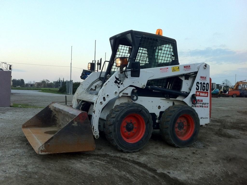 Универсальный и компактный минипогрузчик с бортовым поворотом необходим во всех сферах деятельности, где нужна сила. А к такой сфере относится любой вид деятельности, что подчеркивает богатство функций погрузчика с бортовым поворотом. Сады и парки, узкие … подробнее
 Руководство по техническому обслуживанию 05-серии D905, D1005, D1105, D1305, V1205, V1305, V1505
Технические характеристики Kubota 05-серии D905, D1005, D1105, D1305, V1205, V1305, V1505
объём масла (поддон 125мм) — D905, D1005, D1105 — 5.1л
объём масла (поддон 125мм) — V1305, V1505 — 6.0л
объём масла (поддон 101мм) — D905, D1005, D1105 — 4.0л
объём масла (поддон 101мм) — V1305, V1505 — 4.7л
поверхность головки блока — все модели — 0,05мм
компрессия — все модели — от 29.0 до 33.0 kgf/cm2 — минимальное значение — 23.0 kgf/cm2
зазоры клапанов (на холодную) — 0.145 to 0.185 mm / 0.00571 to 0.00728 in.
Более подробную и детальную техническую информацию вы найдёте в инструкции по ремонту и эксплуатации двигателей Kubota 05-ой серии
ИНСТРУКЦИЯ ПО РЕМОНТУ KUBOTA 05-серии (скачать)
Производитель
Kubota
Если Вас интересует руководство по техническому обслуживанию kubota 05-серии , Вы можете:
Рекомендуем

в наличии
880.00 бел.руб.
.


Ещё из раздела запчасти для Kubota
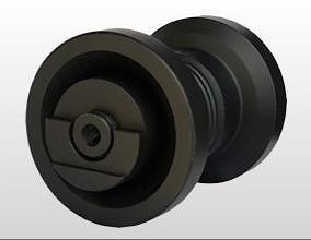
Каток опорный для мини экскаватора Kubota KX61-3/KX71-3/KX91-3 Ролик гусеницы нижний RB517-21705 используетя для мини экскаваторов Kubota U35-3A3 / U35-3A2 / U35-3A / U35-3 / U30-3A2 KX101-3A2 / KX101-3A / KX101-3A3 / KX101-3 / KX71-3 / KX91-3A2 / …
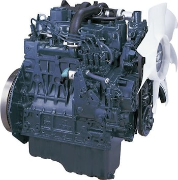
Двигатель Kubota V2203 количество цилиндров 4 Bore x Stroke mm (in) 87.0 x 92.4 (3.43 x 3.64) Объем L (cu.in.) 2.197 (134.07) Combustion System E-TVCS Впускная система Natural aspirated Система охлаждения Radiator cooling Стартер V-A 12-1.4 Масса kg …
Продаем двигатели Kubota V1505 со склада в Минске, а также под заказ У нас вы можете купить двигатель Kubota V1505 и V1505T прямо со склада, в случае отcуcтвия нужного мотора на складе, срок поставки под заказ составляет от 7 до 20 рабочих дней. …
Двигатель Kubota D722 D722-E4B KUBOTA SUPER MINI SERIES Модель D722-E4B Выбросы СО2 Tier 4 F Тип Vertical 4-Cycle liquid cooled Diesel Количество цилиндров 3 диаметр камеры сгорания mm (in) 67 (2.64) ход поршня mm (in) 68 (2.68) Displacement L …
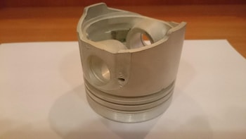
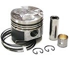
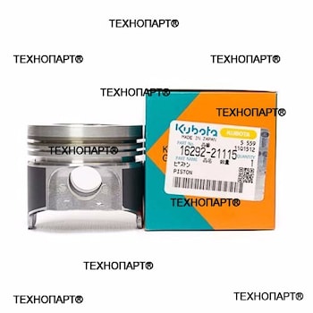
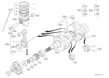
поршень (+0.5) для двигателя Kubota D1105, V1505 поршень (+0.5) для двигателя Kubota D1105, V1505 оригинальный номер Bobcat — 6672374 оригинальный номер Kubota — 16050-2112 OS50 bobcat OEM part number — 6672374 kubota OEM part number — 16050-2112 …
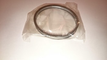
кольца поршневые (+0.5) для двигателя Kubota D1105-B кольца поршневые (+0.5) для двигателя Kubota V1105 оригинальный номер Bobcat — 6672376 оригинальный номер Kubota — 16050- bobcat OEM part number — 6672376 kubota OEM part number — 16050- для мини …
кольца поршневые (std) для двигателя Kubota D722 оригинальный номер Kubota — 1J092-21050 для мини погрузчика Avant 420 и другой техники с двигателем D722 BX1870, BX1870-1, BX1880, GR2120 (Turf tires), GR2120-2, GR2120B-2, ZD1011, ZD221 код двигателя …
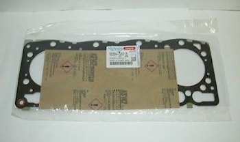
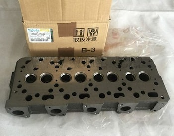
Прокладка головки блока для двигателя Kubota D722 материал прокладки — металл применяемость: мини погрузчика Avant 420 Kubota …
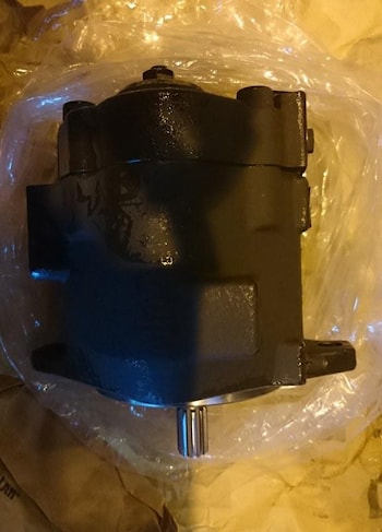
Насос гидравлический аксиально-поршневой RB238-61110 для мини экскаватора Kubota производитель Kubota / Nachi номер детали — RB238-61110, RB238-61112, RG138-61110 Kubota axial piston pump применяемость: Kubota KX018-4, KX41-3, KX41-3V, KX41-3S, …
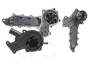
Осуществляем ремонт водяных насосов (помп) от двигателей Кубота. Ремонтируем водяные насосы для Kubota D722, D905, D950, D1503, V1505, V2003, V2203, V2403, V3300, V3800. Гарантия на выполненные работы – до 14 …

Запчасти, детали и расходные материалы для дизельных двигателей Kubota (Кубота) Z482, Z602, D722, D902, D905, D1005, D1105, D1305, V1505, V1503, D1803, V2403, V2607, V3307, V3800, V2203 Японские двигатели Kubota устанавливаются на широкий спектр …
Прокладка головки блока цилиндров для двигателя Kubota V2203 / V2403 прокладка ГБЦ Kubota V2203 номер: 1G790-03310, 1G790-03312, 6685077, 1G79003310, 1G79003312, 6685077 применяемость: Kubota V2203, V2403, KX161-3, KX121-3, L4060, L4240 Bobcat B300, …
в наличии
410.00 бел.руб.
.
Kubota tractors/ excavators/ lawn mower: workshop manuals, operators manuals, wiring diagrams, service manuals and parts catalogs — free download.
|
Title |
File Size |
Download link |
|
Kubota 7001B Service Manual.pdf |
6.4Mb |
Download |
|
Kubota B1200/ B1400/ B1500/ B1600/ B1702/ B1902 Service Repair Manuals + Wiring Diagrams.pdf |
3.3Mb |
Download |
|
Kubota B1550/ B1750 Tractor Operators Manual.pdf |
4.4Mb |
Download |
|
Kubota B1550-B1550HST/ B1750-B1750HST/ B2150-B2150HST Workshop Manual.pdf |
18.8Mb |
Download |
|
Kubota B1550HST/ B1750HST Operators manual.pdf |
6Mb |
Download |
|
Kubota B1700/ B2100/ B2400 Tractor Workshop Manual.pdf |
14.4Mb |
Download |
|
Kubota B1700, B2100, B2400 WSM — Electrical Wiring Diagrams.pdf |
991.6kb |
Download |
|
Kubota B1700, B2100, B2400 WSM Part 2 — Brake assembly.pdf |
15Mb |
Download |
|
Kubota B1820/ B2230/ B2530/ B3030 Tractor Workshop Manual.pdf |
26.9Mb |
Download |
|
Kubota B2050/ B2350/ B2650/ B3150/ WSM Tractor Workshop Manual.pdf |
36.4Mb |
Download |
|
Kubota B2301/ B2601 Tractor Operators Manual.pdf |
2.6Mb |
Download |
|
Kubota B2301, B2601 Tractor Workshop Manual.pdf |
8.1Mb |
Download |
|
Kubota B2320/ B2620/ B2920/ B2320 Narrow — Tractor Operators Manual.pdf |
6.1Mb |
Download |
|
Kubota B2410/ B2710/ B2910 Tractor Workshop Manual.pdf |
18.2Mb |
Download |
|
Kubota B2630/ B3030/ B3000 Tractor Operators Manual.pdf |
2.9Mb |
Download |
|
Kubota B2650/ B3350/ B3350SU Tractor Operators Manual.pdf |
7.5Mb |
Download |
|
Kubota B26TL Tractor Operators Manual.pdf |
4.1Mb |
Download |
|
Kubota B2710/ B2910/ B7800 Tractor Operators Manual.pdf |
6.7Mb |
Download |
|
Kubota B5100/ B6100/ B7100 Shop and Service Manual.pdf |
7.1Mb |
Download |
|
Kubota B5100/ B7100 service manual Parts 2.pdf |
5.5Mb |
Download |
|
Kubota B5100/ B7100 service manual.pdf |
4.7Mb |
Download |
|
Kubota B5100D-E/ B6100D-E/ B7100D Tractor Operators Manual.pdf |
7.8Mb |
Download |
|
Kubota B6000 Tractor Operators Manual.pdf |
10.5Mb |
Download |
|
Kubota B6000 Tractor Service Manual.pdf |
8.5Mb |
Download |
|
Kubota B6100HST-B7100HST Tractor Operators Manual.pdf |
3.4Mb |
Download |
|
Kubota B6200-7200 Tractor Operators Manual.pdf |
6.3Mb |
Download |
|
Kubota B8200 Tractor Operators Manual.pdf |
2.3Mb |
Download |
|
Kubota B9200 Tractor Operators Manual.pdf |
6.1Mb |
Download |
|
Kubota Bx1800 Bx2200 Tractor Workshop Service Manual.pdf |
43.9Mb |
Download |
|
Kubota BX1860, BX2360, BX2660, RCK48-18BX, RCK54-23BX, RCK60B-23BX, RCK48P-18BX, RCK54P-23BX, LA203, LA243 (Tractor, Rotary Mower, Front loader) Workshop Manual.pdf |
16.1Mb |
Download |
|
Kubota BX1870, BX2370, BX2670, RCK48-18BX, RCK54-23BX, RCK60B-23BX, RCK48P-18BX, RCK54P-23BX, LA203, LA243 (Tractor, Rotary Mower, Front loader) Workshop Manual.pdf |
7.5Mb |
Download |
|
Kubota BX1880/ BX2380/ BX2680 Tractor Operators Manual.pdf |
8.1Mb |
Download |
|
Kubota BX2200 Operators Manual.pdf |
4.6Mb |
Download |
|
Kubota BX23S/ LA340/ BT603 Tractor Operators Manual.pdf |
13.2Mb |
Download |
|
Kubota BX23S/ LA340/ BT603/ RCK54D/ RCK60D/ RCK54/ RCK60B (Tractor, Front Loader, Backhoe, Rotary Mower) Workshop Manual.pdf |
11Mb |
Download |
|
Kubota BX25, RCK54(P)-23BX, RCK60B-23BX, LA240, BT601 Workshop Manual.pdf |
19.3Mb |
Download |
|
Kubota F2000 front mower Operators Manual.pdf |
4.1Mb |
Download |
|
Kubota F2690E, F2690, F3990 Front Mower Operators Manual.pdf |
6.4Mb |
Download |

|
Kubota GF1800-R-2 MODELES/ GF1800E-R-2 Front Mount Tractor Operators Manual.pdf |
5.7Mb |
Download |
|
Kubota GR2020G/ GR2120/ GR2120AU Lawn and Garden Tractor Operators Manual.pdf |
5.9Mb |
Download |
|
Kubota L235-L275 Operator’s Manual.pdf |
6.9Mb |
Download |
|
Kubota L2501 Tractor Operators Manual.pdf |
3.4Mb |
Download |
|
Kubota L2501 Tractor Workshop Manual.pdf |
12.9Mb |
Download |
|
Kubota L2900, L3300, L3600, L4200 Tractor Operators Manual.pdf |
4.1Mb |
Download |
|
Kubota L3301/ L3901 Tractor Operators Manual.pdf |
8.6Mb |
Download |
|
Kubota L3560/ L4060/ L4760/ L5060/ L5460/ L6060 Tractor Operators Manual.pdf |
2.4Mb |
Download |
|
Kubota L4701 Tractor Operators Manual.pdf |
8.9Mb |
Download |
|
Kubota L47TL/ M62TL Tractor Operators Manual.pdf |
10.8Mb |
Download |
|
Kubota M5-091/ M5-111 Tractor Operators Manual.pdf |
9.5Mb |
Download |
|
Kubota M5660/ M7060 Tractor Operators Manual.pdf |
8.3Mb |
Download |
|
Kubota M5660SUH/ M5660SUHD Tractor Operators Manual.pdf |
7.9Mb |
Download |
|
Kubota M5L-111 Tractor Operators Manual.pdf |
11Mb |
Download |
|
Kubota M5N-091/ M5N-111/ M4N-071 Tractor Operators Manual.pdf |
12.1Mb |
Download |
|
Kubota M6-101·M6-111/ M6-131·M6-141 Tractor Operators Manual.pdf |
13.9Mb |
Download |
|
Kubota M7-131/ M7-151/ M7-171 Tractor Operators Manual.pdf |
31.6Mb |
Download |
|
Kubota MX4800/ MX5200/ MX5800 Tractor Operators Manual.pdf |
5.1Mb |
Download |
|
Kubota Z122E/ Z121S/ Z125E/ Z125S Lawn and Garden Tractor Operators Manual.pdf |
5.3Mb |
Download |
|
Kubota Z724X/ Z726X Zero Turn Mower Operators Manual.pdf |
5.2Mb |
Download |
|
Kubota ZD1011/ ZD1021 Zero Turn Mower Operators Manual.pdf |
5.8Mb |
Download |
|
Kubota ZD1211/ ZD1211R/ ZD1211L/ ZD1211RL Zero Turn Mower Operators Manual.pdf |
6.3Mb |
Download |
|
Kubota Zd221 Service Repair Manual.pdf |
10Mb |
Download |
|
Kubota ZG222A/ ZG227A Zero Turn Mower Operators Manual.pdf |
5.1Mb |
Download |
|
Title |
File Size |
Download link |
|
Kubota RTV-X1100C Utility Vehicle Operators Manual.pdf |
9Mb |
Download |
|
Kubota RTV-X1140 Utility Vehicle Operators Manual.pdf |
8.5Mb |
Download |
|
Kubota RTV-X900/ RTV-X1120D Utility Vehicle Operators Manual.pdf |
8.4Mb |
Download |
|
Kubota RTV400 Utility Vehicle Operators Manual.pdf |
5.3Mb |
Download |
|
Kubota RTV500 Utility Vehicle Operators Manual.pdf |
5.6Mb |
Download |
|
Title |
File Size |
Download link |
|
Kubota 03-M-E3B SERIES/ 03-M-DI-E3B SERIES/ 03-M-E3BG SERIES Diesel Engine Workshop Manual.pdf |
2.9Mb |
Download |
|
Kubota 05-E2B/ G Series Diesel Engine Workshop Manual.pdf |
3.6Mb |
Download |
|
Kubota 05-Series Diesel Engine Workshop Manual.pdf |
6.8Mb |
Download |
|
Kubota D1005-E3BG/ D1305-E3BG/ D1105-E3BG/ V1505-E3BG Diesel Engine Opertors Manual.pdf |
959.2kb |
Download |
|
Kubota Dl-105-BG2-SAE-1/ 2 Diesel Engine Workshop Manual.pdf |
2.5Mb |
Download |
|
Kubota Engine Model Identification.pdf |
78kb |
Download |
|
Kubota KND2800/ 3200 Diesel Engine Workshop Manual.pdf |
14.1Mb |
Download |
|
Kubota V2607-DI-T-E3-B/ V3307-DI-T-E3-B Diesel Engine Operator Manual.pdf |
1.8Mb |
Download |
|
Kubota V3300-E2B,V3300-T-E2B Diesel Engine Workshop Manual.pdf |
4Mb |
Download |
|
Kubota V3600-E3, V3600-T-E3, V3800-DI-T-E3, V3300-E3BG, V3600-T-E3BG Diesel Engine Operator Manual.pdf |
6.9Mb |
Download |
|
Kubota Z482 Diesel Engine Workshop Manual.pdf |
10.2Mb |
Download |
|
Kubota Z482E, Z602E, D662E, D722E, D782E, D902E Diesel Engine Workshop Manual.pdf |
6.2Mb |
Download |
|
Title |
File Size |
Download link |
|
Kubota U17 Excavator Operators Manual.pdf |
4.8Mb |
Download |
KUBOTA ENGINE SERVICE MANUALS:
Kubota 03 Series Diesel Engine Service Repair Manual
Kubota 05 Series Diesel Engine (D905, D1005, D1105, V1205, V1305, V1505) Service Repair Manual
Kubota EA300-E2-NB1, EA300-E2-NB1-APU, EL300-E2-AR, EL300-E2-AR-KCL Diesel Engine Service Manual
Kubota EA330-E4 Series Diesel Engine Workshop Service Repair Manual
KUBOTA Hyundai V3800-CR-TE4B-HHI-1 , V3800-CR-TIE4B-HHI-1 Diesel Engine Service Repair Manual
Kubota V3800-CR-TE4,V3800-CR-TIE4, V3800-CR-TE4C,V3800-CR-TIE4C Diesel Engine Service Repair Manual
Kubota 03-M Series Diesel Engine Service Repair Manual
Kubota 03-E2B Diesel Engine Service Repair Manual
Kubota 03-M-E3B SERIES, 03-M-DI-E3B SERIES, 03-M-E3BG SERIES Diesel Engine Service Repair Manual
Kubota 07-E3B Diesel Engine Service Repair Workshop Manual
Kubota WG752-E2, DF752-E2 Series Gasoline LPG Engine Service Repair Manual
Kubota SM-E2B Series Diesel Engines Service Repair Manual
Kubota 03-M-DI-E2B Series Diesel Engine Service Repair Manual
Kubota S2200-B , S2600-B , S2800-B Diesel Engine Service Repair Workshop Manual ( NINNA 6.280 HE)
KUBOTA V2003-T-B , F2503-T-B DIESEL ENGINE Service Repair Manual
Kubota V2607-CR-E4B, V2607-CR-TE4B, V3307-CR-TE4B Diesel Engine Service Repair Manual
Kubota V3300-E2B, V3300-T-E2B Diesel Engine Service Repair Manual
Kubota Engine V3800DI-E2B , V3800DI-T-E2B Engine Service Repair Manual (NANNI N4.115)
NANNI T4.155 4.380 TDI 4.390 TDI Engines (4-Cylinders) Service Repair Manual
NANNI T4.165 – T4.180 – T4.200 Marine Diesel Engines Service Repair Manual
Kubota Diadema KND2800, KND3200 Diesel Engines Workshop Service Repair Manual
Tractor Service Manuals:
Kubota B1550 B1750 B2150 (HST) Tractors Service Repair Manual
Kubota B1700 B2100 B2400 Series Tractor Service Repair Manual
Kubota B1710, B2110, B2410, B2710 Tractor Service Repair Manual
Kubota B2410 B2710 B2910 Tractor Service Repair Manual
Kubota B1830, B2230, B2530, B3030 Tractor Service Repair Manual
KUBOTA B5100 B6100 B7100 Tractor Service Repair Manual
Kubota B6100HST , B7100HST Tractor Service Repair Manual
Kubota B6200HST , B7200HST Tractor Service Repair Manual
Kubota BX1870 , BX2370 , BX2670 , RCK48-18BX , RCK54-23BX , RCK60B-23BX , RCK48P-18BX , RCK54P-23BX , LA203A , LA243A Tractor Rotary Mower Front Loader Service Repair Manual
Kubota M128X Tractor Workshop Service Repair Manual
Kubota M130X Tractor Workshop Service Repair Manual
Kubota M100GX , M110GX , M126GX , M128GX , M128GX-FS , M135GX , M135GX-FS Tractors Service Repair Manual
Kubota BX23S , LA340 , BT603 , RCK54D , RCK60D , RCK54 , RCK60B Tractor Service Repair Manual
Kubota B2050 , B2350 , B2650 , B3150 Tractor Service Repair Manual
Kubota BX2350D, RCK48-23BX-EU, RCK54-23BX-EU, RCK60B-23BX-EU, LA243 Tractor, Rotary Mower, Front Loader Service Repair Manual
Kubota F2880, F3680, RCK72-F36, RCK72R-F36, RCK60-F36, RCK60R-F36 Front Cut Ride On Mower Service Repair Manual
Kubota RCK54-24B-EC , RCK60-24B-EC , RCK60-27B-EC , RC60-24BR , RC60-27BR Tractor Service Manual
Kubota MX5000 Tractor Service Repair Manual
Kubota G21LD, G21HD Tractors Workshop Manual
Kubota G23 G26 Ride On Mower Service Repair Workshop Manual
Kubota GR1600EU, GR1600F and GR1600ID Tractors Workshop Service Repair Manual
Kubota GR1600EC2 Tractor Service Repair Manual
Kubota GR2100EC Lawnmower Service Repair Manual
Kubota G2160, G2160-R48S, G2460G Tractors Workshop Manual
Kubota STα-30 STα-35 Sta-30 STa-35 Tractor Workshop Service Repair Manual
Kubota STV32 STV36 STV40 Tractor Service Repair Manual
Kobuta RTV500 UTILITY VEHICLE Workshop Manual
Kobuta RTV900 UTILITY VEHICLE Workshop Manual and Operator Manual
Kobuta RTV1140CPX UTILITY VEHICLE Workshop Manual
Kubota ZD1211 , ZD1211R , ZD1211L , ZD1211RL Tractor Service Repair Manual
Kubota GZD15 (GZD15-LD, GZD15-HD) Zero Turn Mower Service Repair Manual
Kubota ZD21N-EC , ZD21-EC , ZD28-EC Tractor Service Repair Manual
Kubota L260P Tractor Workshop Manual
Kubota L175, L210, L225, L225DT, L260 Tractor Service Repair Manual
Kubota L185, L235, L245, L275, L285, L295, L305, L345, L355 Tractor Service Repair Manual
Kubota LA271 , LA301 , LA351 , LA401 , LA272 , LA302 , LA352 , LA402 Tractor Service Repair Manual
Kubota LA1403 , LA1403EC Front Loader Service Repair Manual
Kubota B2301, B2601 Tractor Service Repair Workshop Manual
Kubota B2320, B2620, B2920 Tractors Workshop Service Repair Manual
Kubota L2350, L2650(GST), L2950(GST), L3450(GST), L3650(GST) Tractors Workshop Manual
Kubota L2501 Tractor Service Repair Workshop Manual
Kubota L3010 , L3410 , L3710 , L4310 , L4610 Tractor Service Repair Manual
Kubota L3130 L3430 L3830 L4630 L5030 Tractor Service Repair Manual
Kubota L3200 Tractor Service Repair Manual
Kubota L3301 , L3901 , L4701 Tractor Service Repair Manual
Kubota L3240, L3540, L3940, L4240, L4740, L5040, L5240, L5740 Tractors Workshop Manual
Kubota L3540, L4240, L5040, L5240, L5740 Tractors Workshop Manual
Kubota L3750, L3750DT, L4150, L4150DT Tractors Workshop Manual
Kubota L4100 Tractor Service Repair Manual ( Language: German)
Kubota M95S-ROPS, M105-ROPS Tractors Workshop Manual
Kubota M108S Tractor Workshop Service Repair Manual (German)
Kubota M110, M120 Tractors Workshop Manual
Kubota M5040, M6040, M7040 Tractors Workshop Manual (ENGLISH)
Kubota M6040 , M7040 Tractor Service Repair Manual (German)
Kubota M6800, M6800S, M8200, M9000 Tractor Workshop Service Repair Manual
Kubota M8540, M9540 Tractors Workshop Service Repair Manual
Kubota TG1860, TG1860G Lawn Garden Tractor Workshop Manual
Kubota T1880, T2080, T2380 Lawn Garden Tractor Workshop Manual
Kubota ZD18, ZD21, ZD28, ZD18F, ZD21F, ZD28F Zero Turn Mowers Workshop Manual
Kubota ZD221-48, ZD221-54 Zero Turn Mower Workshop Service Repair Manual (ZD221)
Kubota ZD321N , ZD321 , ZD323 , ZD326S , ZD326P , ZD331P , ZD331LP Zero Turn Mowers Service Repair Manual
Kubota ZD326-EU Tractor Service Repair Manual (English)
Kubota ZD326-EU Tractor Service Repair Manual (German)
Kubota ZG327 Zero Turn Mower Workshop Manual
Kobuta Excavator Service Manuals:
KUBOTA KC70 DUMPER Service Repair Manual
KUBOTA KC100HD DUMPER Service Repair Manual
KUBOTA KC250H, KC250HR DUMPER Service Repair Manual
Kubota K008-3, U10-3 Excavator Service Repair Manual
Kubota R420S, R520S, R420α, R520α Wheel Loader Service Repair Manual
KUBOTA U10, U20, U35, U45 MICRO EXCAVATOR Service Repair Manual
Kubota U15, U15-3 Excavator Service Repair Manual
KUBOTA U17-3α MICRO EXCAVATOR Service Repair Manual
KUBOTA U48-4, U55-4 EXCAVATOR Service Repair Manual
Kubota KH36 KH41 KH51 KH61 KH66 KH91 KH101 KH151 Excavator Service Repair Manual
Kubota KX61-3, KX71-3 Excavator Workshop Service Manual
Kubota KX080-3 Excavator Workshop Service Repair Manual
Kubota KX080-4 Excavator Workshop Service Repair Manual
Kubota KX91-3S α, KX101-3α, KX121-3S α, KX161-3S α, U35S, U35-3S α, U45-3S α Excavator Minor change Chapter WSM
Kubota Parts Manuals Download
Вы здесь
Перейти к полной версии/Вернуться
сб, 16.04.2022 — 19:26
#1

Wisconsin, USA — Висконсин, США.
Регистрация: 07.10.2020 — 06:16
: 600
Не в сети
Заходил: 1 час 54 минуты назад

пт, 18.11.2022 — 09:07
#2
Регистрация: 17.11.2022 — 12:03
: 9
Не в сети
Заходил: 1 месяц 3 недели назад
Не могу найти инструкцию по ремонту кубота в — 1600, нужна помощь, к кому обращаться?
вт, 29.11.2022 — 05:58
#3
Wisconsin, USA — Висконсин, США.
Регистрация: 07.10.2020 — 06:16
: 600
Не в сети
Заходил: 1 час 54 минуты назад
Mikhai пишет:
Не могу найти инструкцию по ремонту кубота в — 1600, нужна помощь, к кому обращаться?
| Вложение |
|---|
 |
пн, 12.12.2022 — 08:01
#4
Регистрация: 12.12.2022 — 07:34
: 2
Не в сети
Заходил: 4 месяца 1 неделя назад
Доброго времени суток! Нужен мануал на Кубота GL53!
чт, 29.12.2022 — 05:56
#5
Wisconsin, USA — Висконсин, США.
Регистрация: 07.10.2020 — 06:16
: 600
Не в сети
Заходил: 1 час 54 минуты назад
марсель варисович пишет:
Доброго времени суток! Нужен мануал на Кубота GL53!
| Вложение |
|---|
|
вс, 12.03.2023 — 20:47
#6
Wisconsin, USA — Висконсин, США.
Регистрация: 07.10.2020 — 06:16
: 600
Не в сети
Заходил: 1 час 54 минуты назад
Kubota GT3 GT5 GT8

| Вложение |
|---|
|
вт, 21.03.2023 — 05:00
#7
Wisconsin, USA — Висконсин, США.
Регистрация: 07.10.2020 — 06:16
: 600
Не в сети
Заходил: 1 час 54 минуты назад
| Вложение |
|---|
|
вс, 23.04.2023 — 02:36
#8
Wisconsin, USA — Висконсин, США.
Регистрация: 07.10.2020 — 06:16
: 600
Не в сети
Заходил: 1 час 54 минуты назад
KUBOTA B10

| Вложение |
|---|
|

Самые популярные темы
- ПЛАЗМОРЕЗЫ. ПЛАЗМЕННАЯ РЕЗКА МЕТАЛЛОВ. ДУГОВАЯ СВАРКА. АРГОННАЯ СВАРКА. РАСХОДНИКИ. НОВЫЕ ТЕХНОЛОГИИ
- Руководства по эксплуатации зерноуборочных комбайнов.
- Руководства по эксплуатации и ремонту тракторов
- РУКОВОДСТВО ПО ПРЕСС ПОДБОРЩИКАМ
- Навигация в поле — параллельное вождение.
- Комбайн CLAAS Consul
- Руководства по эксплуатации и ремонту экскаваторов
- Сеялки.
- Каталоги инструкции к сельхоз технике
- Разбрасыватели удобрений