![]()
![]()
Импорт промышленного оборудования


Linak DK 6430
Компания Linak предлагает решения на основе электрических линейных приводов, которые обеспечивают плавность движения различного оборудования. Изделия находят применение в различных отраслях, начиная от сельского хозяйства и средств промышленной автоматизации до медицинского оборудования, мебели повышенной комфортности и предметов интерьера. Продукция создается профессионалами с использованием инноваций и имеет высокое качество, что делает ее востребованной по всему миру. Линейные приводы этого бренда имеют длительный срок действия и продолжают работать, когда другие выходят из строя.
.jpg)
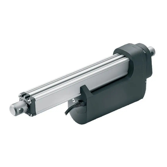
Линейные приводы преобразуют вращательное движение двигателя в действие толкающего или тянущего типа. Linak DK 6430 Nordborg купить стоит для тех ситуаций, когда требуется простое, безопасное и плавное передвижение с точным и удобным управлением. Для таких ситуаций данный привод – идеальное решение. Он также отлично подходит для областей применения, где требуется наклон, подъем, натяжение и толкание. Привод DK 6430 Linak идеально подходит для применения в условия, требующих коротких линейных перемещений. Устройство зарекомендовало себя прочным и надежным, которое отлично выполняет свои функции практически в любых ситуациях.
Компания выпускает линейные приводы:
- Актуаторы — устройства, которым требуется вход источника энергии, вход внешнего сигнала, оба из которых затем создают выход, обычно в форме движения, которое может быть либо вращательным, либо линейным.
- Подъемные колонны — обеспечивают более длинный ход, поскольку имеют несколько ступеней, что позволяет им растягиваться и сокращаться на большую длину, чем в полностью закрытом состоянии.
- Пульты – устройства, которые регулируют воздействие блока на актуатор и обеспечивают движение.
- Блоки управления – большое семейство интеллектуальных блоков, позволяющих производить регулировку при различных применениях актуаторов.
Достоинства линейных приводов Linak
Linak DK 6430 — чрезвычайно выносливый, удобный в интеграции и простой в установке привод, который расширяет функциональность оборудования и придает ему особую стойкость.
.jpg)
Линейные приводы этого бренда имеют следующие преимущества:
- Готовы к установке системы в комплекте с различными двигателями и блоками управления;
- имеют широкий ассортимент конфигурируемых решений практически под любые нужды;
- выпускают все основные типы приводов, имеющиеся на рынке;
- являются универсальными многокоординатными системами на основе линейных модулей;
- обладают высокой эффективностью и надежностью;
- имеют доступный по всему миру сервис от местных представительств.
Актуаторные системы и блоки управления обеспечивают предоставление преимуществ в больницах и офисах, системах сточных вод и оборудования, применяемого в экстремальных условиях, в сельскохозяйственном и строительном секторе.
- Manuals
- Brands
- Linak Manuals
- Controller
- ACTUATOR LA36
- User manual
-
Contents
-
Table of Contents
-
Troubleshooting
-
Bookmarks
Quick Links
U S E R M A N U A L
ACTUATOR LA36
To learn more about LINAK, please visit:
w w w . l i n a k . c o m
Page 1 of 76
Related Manuals for Linak LA36
Summary of Contents for Linak LA36
-
Page 1
U S E R M A N U A L ACTUATOR LA36 To learn more about LINAK, please visit: w w w . l i n a k . c o m Page 1 of 76… -
Page 2
Page 2 of 76… -
Page 3: Table Of Contents
Contents Preface …………………………5 LINAK application policy ……………………6 Chapter 1 Safety instructions ……………………..7-8 Chapter 2 Mounting guidelines ……………………9-10 Mounting of cables ……………………..11 Electrical installation: ……………………..12 Actuator without feedback …………………..12 Actuator with: Endstop signal output ………………..13-14 Relative positioning — Dual Hall ………………. 15-16 Endstop signals and relative positioning — Dual Hall …………
-
Page 4
12V motor ………………………61 24V motor ………………………62 36V motor ………………………63 Label for LA36 ………………………64 Key to symbols ………………………64 LA36 Ordering example Econ ………………….65 LA36 Ordering example ……………………66 Chapter 5 Maintenance ……………………….67 Repair and spare parts ……………………67 Main groups of disposal ……………………67 Warranty ……………………….68… -
Page 5: Preface
LINAK provides a warranty on all its products. This warranty, however, is subject to correct use in accordance with the specifications, maintenance being done correctly and any repairs being carried out at a service centre, which is authorised to repair LINAK products.
-
Page 6: Linak Application Policy
LINAK shall be responsible solely that LINAK products comply with the specifications set out by LINAK and it shall be the responsibility of the LINAK customer to ensure that the specific LINAK product can be used for the application in question.
-
Page 7: Safety Instructions
Chapter 1 Safety instructions Please read this safety information carefully: Be aware of the following three symbols throughout the user manual: Warning! Failing to follow these instructions can cause accidents resulting in serious personal injury. Recommendations Failing to follow these instructions can result in the actuator suffering damage or being ruined.
-
Page 8
• Only use the actuator within specified working limits. • When mounting the LA36 in the application ensure that the bolts can withstand the wear and that they are secured safely. • If irregularities are observed, the actuator must be replaced. -
Page 9: Mounting Guidelines
In applications with high dynamic forces LINAK recommends not to use the fully extended or retracted position over longer time, as this can damage the endstop system permanently.
-
Page 10
It is the application manufacturer’s responsibility to incorporate a suitable safety arrangement, which will prevent personal injury from occurring, if the actuator should fail Warning! LINAK’s actuators are not designed for use within the following fields: • Offshore installations •… -
Page 11: Mounting Of Cables
1.5 ± 0.3 Nm TORX 25IP When changing the cables on a LINAK actuator, it is important that this is done carefully, in order to protect the plugs and pins. Before the new cable is mounted, we recommend that the socket is greased with vaseline, to keep the high IP protection and ensure an easy mounting.
-
Page 12: Electrical Installation
Electrical installation: Actuator without feedback: Connection diagram: Fig. 1 : 36xxxxx00/10xxxxxx 36xxxxxxx000xx-xxxxxxxxxxxxxxx BROWN BLUE I/O specifications: Input/Output Specification Comments Description Permanent magnetic DC motor. See connection diagram, fig. 1 above Brown 12, 24 or 36VDC (+/-) To extend actuator: Connect Brown to positive 12V ±…
-
Page 13: Endstop Signal Output
Actuator with endstop signal output: Connection diagram: Fig. 2 : 36xxxxx20xxxxxx 36xxxxxxx000xx-xxxxxxxxxxxxxxx BROWN BLUE YELLOW* GREEN* BLACK *YELLOW/GREEN: Endstop signals out are NOT potential free! If you wish to use the endstop signals, you will have to keep power on the brown, blue, red and black wires, otherwise the signal will be lost.
-
Page 14
Actuator with endstop signal output: I/O specifications: Input/Output Specification Comments Description The actuator can be equipped with electronically controlled endstop signals out. See connection diagram, fig. 2 on page 13 Brown 12, 24 or 36VDC (+/-) To extend actuator: Connect Brown to positive 12V ±… -
Page 15: Relative Positioning — Dual Hall
Actuator with relative positioning — Dual Hall: Connection diagram: Fig. 3 : 36xxxxx0H/1Hxxxxxx 36xxxxxxxH00xx-xxxxxxxxxxxxxxx BROWN BLUE YELLOW GREEN BLACK Page 15 of 76…
-
Page 16: Relative Positioning — Dual Hall
Overvoltage on the motor can per pulse result in shorter pulses. LA365A Actuator = 2.9 mm N.B. For more precise measure- per pulse ments, please contact LINAK A/S. Violet Not to be connected White Not to be connected Diagram of Dual…
-
Page 17: Endstop Signals And Relative Positioning — Dual Hall
Actuator with endstop signals and relative positioning — Dual Hall: Connection diagram: Fig. 4 : 36xxxxx2Hxxxxxx 36xxxxxxxH00xx-xxxxxxxxxxxxxxx BROWN BLUE VIOLET* WHITE* YELLOW GREEN BLACK *VIOLET/WHITE: Endstop signals out are NOT potential free! If you wish to use the endstop signals, you will have to keep power on the brown, blue, red and black wires, otherwise the signal will be lost.
-
Page 18
Overvoltage on the motor can mm per pulse result in shorter pulses. LA365A Actuator = 2.9 N.B. For more precise measure- mm per pulse ments, please contact LINAK A/S. Violet Endstop signal in Output voltage min. V — 2V Source current max. 30mA… -
Page 19: Relative Positioning — Single Hall
Actuator with relative positioning — Single Hall: Connection diagram: Fig. 5 : 36xxxxx0K/1Kxxxxxx 36xxxxxxxK00xx-xxxxxxxxxxxxxxx BROWN BLUE VIOLET BLACK Page 19 of 76…
-
Page 20
N.B. For more precise LA363B: Actuator = 0.3 mm per count measurements, please contact LA363A: Actuator = 0.4 mm per count LINAK A/S. LA365A: Actuator = 0.7 mm per count Low frequency with a high load. Frequency: Higher frequency with no load. -
Page 21: Endstop Signals And Relative Positioning — Single Hall
Actuator with endstop signals and relative positioning — Single Hall: Connection diagram: Fig. 6 : 36xxxxx2Kxxxxxx 36xxxxxxxK00xx-xxxxxxxxxxxxxxx BROWN BLUE YELLOW* GREEN* VIOLET BLACK *YELLOW/GREEN: Endstop signals out are NOT potential free! If you wish to use the endstop signals, you will have to keep power on the brown, blue, red and black wires, otherwise the signal will be lost.
-
Page 22: Endstop Signals And Relative Positioning — Single Hall
N.B. For more precise LA363B: Actuator = 0.3 mm per count measurements, please contact LA363A: Actuator = 0.4 mm per count LINAK A/S. LA365A: Actuator = 0.7 mm per count Low frequency with a high load. Frequency: Higher frequency with no load.
-
Page 23: Absolute Positioning — Analogue Feedback
Actuator with absolute positioning — Analogue feedback: Connection diagram: Fig. 7 : 36xxxxx1B/1Cxxxxxx 36xxxxxxxB00xx-xxxxxxxxxxxxxxx 36xxxxxxxC00xx-xxxxxxxxxxxxxxx BROWN BLUE VIOLET BLACK Page 23 of 76…
-
Page 24
Actuator with absolute positioning — Analogue feedback: I/O specifications: Input/Output Specification Comments Description The actuator can be equipped with electronic circuit that gives an analogue feedback signal when the actuator moves. See connection diagram, fig. 7, page 23 Brown 12, 24 or 36VDC (+/-) To extend actuator: Connect Brown to positive 12V ±… -
Page 25: Endstop Signals And Absolute Positioning — Analogue Feedback
Actuator with endstop signals and absolute positioning — Analogue feedback: Connection diagram: Fig. 8 : 36xxxxx2B/2Cxxxxxx 36xxxxxxxB00xx-xxxxxxxxxxxxxxx 36xxxxxxxC00xx-xxxxxxxxxxxxxxx BROWN BLUE YELLOW* GREEN* VIOLET BLACK *YELLOW/GREEN: Endstop signals out are NOT potential free! If you wish to use the endstop signals, you will have to keep power on the brown, blue, red and black wires, otherwise the signal will be lost.
-
Page 26
Actuator with endstop signals and absolute positioning — Analogue feedback: I/O specifications: Input/Output Specification Comments Description The actuator can be equipped with electronic circuit that gives an analogue feedback signal when the actuator moves. See connection diagram, fig. 8, page 25 Brown 12, 24 or 36VDC (+/-) To extend actuator:… -
Page 27: Absolute Positioning — Mechanical Potentiometer Feedback
Actuator with absolute positioning — Mechanical potentiometer feedback: Connection diagram: Fig. 9 : 36xxxxx0P/1Pxxxxxx 36xxxxxxxP00xx-xxxxxxxxxxxxxxx BROWN BLUE WHITE (VCC+ to POT) VIOLET BLACK Page 27 of 76…
-
Page 28: Absolute Positioning — Mechanical Potentiometer Feedback
Actuator with absolute positioning — Mechanical potentiometer feedback: I/O specifications: Input/Output Specification Comments Description The actuator can be equipped with a mechanical potentiometer, 10 kohm. See connection diagram, fig. 9, page 27 Bourns 0-10 kohm, 5%, 10-Turn Type: 3540 Wirewound Brown 12, 24 or 36VDC (+/-) To extend actuator:…
-
Page 29: Endstop Signals And Absolute Positioning — Mechanical Potentiometer Feedback
Actuator with endstop signals and absolute positioning — Mechanical potentiometer feedback: Connection diagram: Fig. 10 : 36xxxxx2Pxxxxxx 36xxxxxxxP00xx-xxxxxxxxxxxxxxx BROWN BLUE YELLOW* GREEN* WHITE (VCC+ to POT) VIOLET BLACK *YELLOW/GREEN: Endstop signals out are NOT potential free! If you wish to use the endstop signals, you will have to keep power on the brown, blue, red and black wires, otherwise the signal will be lost.
-
Page 30
Actuator with endstop signals and absolute positioning — Mechanical potentiometer feedback: I/O specifications: Input/Output Specification Comments Description The actuator can be equipped with a mechanical potentiometer, 10 kohm. See connection diagram, fig. 10, page 29 Bourns 0-10 kohm, 5%, 10-Turn Type: 3540 Wirewound Brown 12, 24 or 36VDC (+/-) -
Page 31: Absolute Positioning — Pwm
Actuator with absolute positioning — PWM: Connection diagram: Fig. 11 : 36xxxxx15/16xxxxxx 36xxxxxxxF00xx-xxxxxxxxxxxxxxx BROWN BLUE VIOLET BLACK Page 31 of 76…
-
Page 32: Absolute Positioning — Pwm
Actuator with absolute positioning — PWM: I/O specifications: Input/Output Specification Comments Description The actuator can be equipped with electronic circuit that gives an analogue feedback signal when the actuator moves. See connection diagram, fig. 11, page 31 Brown 12, 24 or 36VDC (+/-) To extend actuator: Connect Brown to positive 12V ±…
-
Page 33: Endstop Signals And Absolute Positioning — Pwm
Actuator with endstop signals and absolute positioning — PWM: Connection diagram: Fig. 12 : 36xxxxx25/26xxxxxx 36xxxxxxxF00xx-xxxxxxxxxxxxxxx BROWN BLUE YELLOW* GREEN* VIOLET BLACK *YELLOW/GREEN: Endstop signals out are NOT potential free! If you wish to use the endstop signals, you will have to keep power on the brown, blue, red and black wires, otherwise the signal will be lost.
-
Page 34
Actuator with endstop signals and absolute positioning — PWM: I/O specifications: Input/Output Specification Comments Description The actuator can be equipped with electronic circuit that gives an analogue feedback signal when the actuator moves. See connection diagram, fig. 12, page 33 Brown 12, 24 or 36VDC (+/-) To extend actuator:… -
Page 35: Old Cs36 (H-Bridge) Version — Dual Hall
Actuator with old CS36 (H-bridge) version — Dual Hall: Connection diagram: Fig. 13 : 36xxxxx30/3Hxxxxxx BROWN BLUE INWARDS VIOLET OUTWARDS WHITE H-Bridge YELLOW GREEN BLACK Page 35 of 76…
-
Page 36
Actuator with old CS36 (H-bridge) version — Dual Hall: I/O specifications: Input/Output Specification Comments Description The actuator can be equipped with old version of integrated controller. See connection diagram, H-Bridge fig. 13, page 35 Brown To extend actuator: Connect Brown to positive Only available with 24VDC (+/-) To retract actuator: 24V ±… -
Page 37: Old Cs36 (H-Bridge) Version — Endstop Signals
Actuator with old CS36 (H-bridge) version — Endstop signals: Connection diagram: Fig. 14 : 36xxxxx40xxxxxx BROWN BLUE INWARDS VIOLET OUTWARDS WHITE H-Bridge YELLOW* GREEN* BLACK *YELLOW/GREEN: Endstop signals out are NOT potential free! If you wish to use the endstop signals, you will have to keep power on the brown, blue, red and black wires, otherwise the signal will be lost.
-
Page 38
Actuator with old CS36 (H-bridge) version — Endstop signals: I/O specifications: Input/Output Specification Comments Description The actuator can be equipped with old version of integrated controller. See connection diagram, H-Bridge fig. 14, page 37 Brown To extend actuator: Connect Brown to positive Only available with 24VDC (+/-) To retract actuator: 24V ±… -
Page 39: Ic Basic
Actuator with IC Basic: Connection diagram: Fig. 15 : 36xxxxx7xxxxxxx 36xxxxxxxx03xx-xxxxxxxxxxxxxxx BROWN 12/24V DC BLUE INWARDS BLACK OUTWARDS H-Bridge FEEDBACK VIOLET Hall SIGNAL GND WHITE 0-10V Please be aware that if the power supply is not properly connected, you might damage the actuator! Page 39 of 76…
-
Page 40
Actuator with IC Basic: I/O specifications: Input/Output Specification Comments Description Easy to use interface with integrated power electronics (H-bridge). The actuator can also be equipped with electronic circuit that gives an absolute or relative feedback signal. The version with “IC option” H-Bridge cannot be operated with PWM (power supply). -
Page 41
Actuator with IC Basic: I/O specifications: Input/Output Specification Comments Violet Analogue feedback Standby power consumption: 12V, 60mA 0-10V (Option 7.2) 24V, 45 mA Ripple max. 200mV Transaction delay 20ms Linear feedback 0.5% Max. current output: 1mA It is recommendable to have the actuator to activate its limit switches on a regular basis, to ensure more precise positioning… -
Page 42: Ic Advanced — With Buslink
BusLink is available for IC Advanced and can be used for: Diagnostics, manual run and configuration Download BusLink software here: http://www.linak.com/techline/?id3=2363 For more information and easy set-up of BusLink, please follow this link to view the Quick Guide for BusLink: http://www.linak.com/techline/?id3=2356…
-
Page 43
Actuator with IC Advanced — with BusLink: I/O specifications: Input/Output Specification Comments Description Easy to use interface with integrated power electronics (H-bridge). The actuator can also be equipped with electronic circuit that gives an absolute or relative feedback signal. IC Advanced provides a wide range of possibilities for customisation. -
Page 44: Ic Advanced — With Buslink
Actuator with IC Advanced — with BusLink: I/O specifications: Input/Output Specification Comments Violet Analogue feedback (0-10V): Ripple max. 200mV Configure any high/low Transaction delay 20ms combination between 0-10V Linear feedback 0.5% Max. current output. 1mA Single Hall output (PNP) Output voltage min. V — 2V Max.
-
Page 45: Correct Wiring Of Power Gnd And Signal Gnd For Ic Basic And Ic Advanced
Power supply BLUE POWER GND Control connector Hall VIOLET FEEDBACK 0-10V Feedback input WHITE SIGNAL GND 4-20mA LA36 IC actuator Please note that this section only applies for the following feedback options: 0-10V, Hall and PWM. Page 45 of 76…
-
Page 46: Actuator With Parallel
Actuator with Parallel: Connection diagram: Fig. 17 : 36xxxxx9xxxxxxx 36xxxxxxxx03xx-xxxxxxxxxxxxxxx Actuator 8 Actuator 7 Actuator 6 Actuator 5 Actuator 4 Actuator 3 Actuator 2 Actuator 1 BROWN 12/24V DC Communi- cation Communi- BLUE cation Communi- cation Communi- cation Communi- VIOLET cation Communi- cation…
-
Page 47
Actuator with Parallel: I/O specifications: Input/Output Specification Comments Description Parallel drive of up to 8 actuators. A master actuator with an integrated H-bridge controller controls up to 7 slaves. H-Bridge The version with “IC option” H-Bridge cannot be operated with PWM (power supply). -
Page 48
Actuator with Parallel: I/O specifications: Input/Output Specification Comments Green Endstop signal out Output voltage min. V — 2V Source current max. 100mA Yellow Endstop signal in NOT potential free Violet Parallel communication: Standby power consumption: Violet cords must be connected 12V, 60mA together 24V, 45mA… -
Page 49: The Parallel System
The parallel system: The parallel drive function will support a number of actuators working jointly. The system is self-configurable and when connected, a Master will be dedicated. The Master will then control up to 7 slaves. It is both possible to run parallel with a single power supply, or to run each actuator with separate power supplies.
-
Page 50: The Parallel System
The broken actuator needs to be replaced, before the system can run again. The system will only run, when it is complete • If you need to add an additional actuator to the parallel system, please contact your local LINAK supplier. The system will need to be re-programmed BusLink is available for Parallel •…
-
Page 51: System Monitoring For Parallel
System Monitoring for Parallel If one of the actuators have one of the following error conditions, the actuator will immediately STOP: • H-Bridge fault • Out of the temperature range (High duty cycle protection) • Overcurrent (Current cut-off if one or all actuators go in mechanical block) •…
-
Page 52: Troubleshooting
• Check wire connection (Red/ Wrongly connected: Black) on control unit + Brown, — Blue Signal required for moving • Please contact LINAK outwards: + VCC -> RED Wire Signal required for moving inwards: + VCC -> Black Wire Excessive electricity Misalignment or overload in •…
-
Page 53: Troubleshooting
Connect actuator to BusLink and to BusLink check current parameters. Initialise the actuator in both directions • Please contact LINAK Motor runs too slowly Load is higher than specified • Reduce load or does not run with Voltage drop in cable (Use of long…
-
Page 54: Troubleshooting For Parallel
Troubleshooting for Parallel: Symptom Possible cause Action No actuators in Power supply • Check power supply source and movement power connections: Brown + Blue — Please be aware that if the power supply is not properly connected, you might damage the actuator Signal connections •…
-
Page 55
Troubleshooting for Parallel: Symptom Possible cause Action Signal cable damaged All actuators stop at the same • When seeing a communication or removed under position error, the system goes into operation ‘position lost’ • The signal and power cables MUST be connected to all actuators again •… -
Page 56: Troubleshooting For Parallel
In/Out signals must be removed before next movement For more information and easy set-up of BusLink, please follow this link to view the Quick Guide for BusLink: http://www.linak.com/techline/?id3=2356 Be aware of Modbus actuator — please see the Modbus installation guide. http://www.linak.com/techline/?id3=2363…
-
Page 57: Specifications
Safety device regarding functional failure of the nut (Safety nut): The LA36 has a built-in safety nut in push as an option. Actuators with safety nut in push can only function when used in push applications. The safety nut comes into operation should the main nut fail.
-
Page 58: Actuator Dimensions
Actuator dimensions TECHLINE LA36: ® 01= Standard ST R O KE <= 3 0 0 = 200 + STR OKE ST R O KE => 30 0 = 250 + STRO KE 02= Turned 90° 02= Turned 90˚ 01= Standard S TR OKE <= 30 0 = 18 8 + S TR O KE…
-
Page 59: Built-In Dimensions
Built-in dimensions Piston rod “0” /from the surface “1” / to the centre of “2” / to the centre of “3” / from the surface the hole the hole Back fixture Stroke <=300 Stroke Stroke <=300 Stroke Stroke <=300 Stroke Stroke <=300 Stroke >…
-
Page 60: Manual Hand Crank
Manual Hand Crank The manual hand crank can be used in the case of power failure. 6 mm Allen key The cover over the Allen key socket must be unscrewed before the Allen key can be inserted and the hand crank operated. Hand Crank Torque: 6 — 8 Nm Piston rod movement per turn, app.: 8 mm…
-
Page 61: Speed And Current Curves
Speed and current curves — 12V motor The values below are typical values and made with a stable power supply and an ambient tem- perature of 20˚C. LA36 12V motor current vs. load 20mm/ 8mm/ 12mm/ F gear 12mm/ 12mm/…
-
Page 62: Motor
Speed and current curves — 24V motor The values below are typical values and made with a stable power supply and an ambient tem- perature of 20˚C. LA36 24V motor current vs. load 20mm 20mm/ 12mm/ 12mm/ 8mm/ 12mm/ E gear…
-
Page 63: Motor
Speed and current curves — 36V motor The values below are typical values and made with a stable power supply and an ambient tem- perature of 20˚C. LA36 36V motor current vs. load 12mm/ 8mm/ 20mm/ 12mm/ 20mm/ 12mm/ H gear…
-
Page 64: Label For La36
7. W/O #1234567-0001 The LINAK work order followed by a unique sequential identification number Key to symbols: The following symbols are used on the LA36 label:…
-
Page 65: La36 Ordering Example Econ
Safety : A = Safety nut Stroke Length: XXX = mm. Spindle Pitch: 080 = 8 mm 120 = 12 mm 200 = 20 mm Actuator Type: 36 = LA36 IC options: LINbus Modbus Parallel � � � � LA36 actuator:…
-
Page 66: La36 Ordering Example
LA36 0 = No cable COMBINATION CODE NOS. LA36 Ordering example 1 = 1.5 m power cable (0367046-1500) 2 = 5 m power cable (0367046-5000) 36 0 0 0 0 + 0 0 0 0 0 0 3 = 0.2 m power cable with AMP connector…
-
Page 67: Maintenance
If a system is opened by unauthorised personel there is a risk that it may malfunction at a later date. Spare parts LINAK can supply spindle parts and motor parts as spare parts. Please indicate the designation from the label when ordering spare parts from your nearest authorised LINAK dealer.
-
Page 68: Warranty
There is an 18 months’ warranty on TECHLINE products against manufacturing faults calculated from the production date of the individual products (see label). LINAK’s warranty is only valid in so far as the equipment has been used and maintained correctly and has not been tampered with. Furthermore, the actuator must not be exposed to violent treatment.
-
Page 69: Declarations Of Conformity
Smedevænget 8 DK — 6430 Nordborg hereby declares that LINAK Actuator 36xxxxx0xxxxxx, 36xxxxx1xxxxxx, 36xxxxx2xxxxxx, 36xxxxx5xxxxxx complies with the EMC Directive: 2014/30/EU according to following standards: EN 55016-2-1:2009, EN 55016-2-3:2010+A1+AC, EN 55022:2011+AC Class B, EN 55025:2008 EN 61000-4-2:2009, ISO 10605:2008, EN 61000-4-3:2006+A1, ISO 11452-2:2004, EN 61000-4-5:2006,…
-
Page 70
Smedevænget 8 DK — 6430 Nordborg hereby declares that Actuator 36xxxxxADxxxBxx (LA36 BUS) complies with the EMC Directive: 2014/30/EU according to following standards: EN 61000-6-1:2007, EN 61000-6-2:2005, EN 61000-6-3:2007, EN 61000-6-4:2007 complies with RoHS2 Directive 2011/65/EU according to the standard:… -
Page 71: Declarations Of Conformity
DECLARATION OF CONFORMITY LINAK A/S Smedevænget 8 DK — 6430 Nordborg Hereby declares that Actuator LA36IC (36xxxxx7xxxxxxx, 36xxxxx8xxxxxxx, 36xxxxx9xxxxxxx, 36xxxxxBxxxxxxx) LA36IC (36xxxxxxxx03xxxxxxxxxxxxxxxxxx) complies with the EMC Directive 2014/30/EU according to following harmonized standards: EN 61000-4-2:2009, EN 61000-4-3:2006+A1+A2, EN 61000-4-4:2012, EN 61000-4-5:2014, EN 61000-4-6:2014, EN…
-
Page 72: Declaration Of Incorporation Of Partly Completed Machinery
Linear Actuators LA12, LA14, LA22, LA23, LA25, LA30, LA35, LA36, LA37 comply with the following parts of the Machinery Directive 2006/42/EC, ANNEX I, Essential health and safety requirements relating to the design and construction of machinery: 1.5.1 Electricity supply…
-
Page 73
Page 73 of 76… -
Page 74
Page 74 of 76… -
Page 75
Page 75 of 76… -
Page 76: Adresses
LINAK. INDIA All sales are subject to the Standard Terms of Sale and Delivery for LINAK. Mechatronics Control Equipments India Pvt Ltd For a copy hereof, please contact LINAK. Phone: +91-44-28558484/85, E-mail: bala@mechatronicscontrol.com…
This manual is also suitable for:
Techline la36
Принимаем оплату российскими картами, выкупаем и доставляем ваши заказы из магазинов США и Германии. Наша доставка работает в стандартном режиме.
×
Сейчас вы находитесь в городе Москва
Выберите город, в который Вы хотите осуществить доставку


![]()
![]()
Вопрос по товару?
Мы перезвоним!
Основные характеристики
Группа товаров:
Линейные приводы
Оригинальное название:
Linak DK 6430 Nordborg 230446-00 Actuator
Товар из США
Доставим в Ваш город
Артикул:266199686542
Продавец:
oneclickwarehouse
(43215)
Местонахождение:Ogden, Utah, US
Доставка до склада США
Бесплатно

Товары из магазинов
США и Европы
без наценок!
Отправили
67 000 посылок
с 2008 года!
Знаменитый
каталог eBay
на русском языке!
Доставка курьером
до двери
Почтой или в удобный пункт выдачи!
Похожие товары
Linak DK 6430 Nordborg 230446-00 Actuator
Linak DK 6430 Nordborg 230446-00 Actuator – можно купить на shopozz.ru с доставкой
из Ogden, Utah, US. Все товары из
категории «Линейные приводы» быстро и вовремя доставляются в Россию и страны СНГ.
Полную информацию о доставке можно посмотреть в разделе «Доставка».
На товары категории «Линейные приводы» действует доступная цена,
поэтому Linak DK 6430 Nordborg 230446-00 Actuator можно
приобрести всего за
27526 руб.
Не можете сделать выбор? Посмотрите другие товары продавца
oneclickwarehouse
(43215)
–
«Смотреть все товары».
Возникли вопросы о товаре, условиях оплаты либо доставки?
Закажи обратный
звонок!
Другие бренды категории
В чем наша ценность
Покупки без ограничений
- Доставка в любой город СНГ
- Простой процесс оплаты
- Каталог на русском языке
Доступ к 3 млн. товаров
- Доставка в любой город СНГ
- Простой процесс оплаты
- Каталог на русском языке
Консолидация и сервис
- Доставка в любой город СНГ
- Простой процесс оплаты
- Каталог на русском языке
Покупки в США и Европе — это просто
Вы делаете заказ — мы выкупаем товары и доставляем вам
Склад

$46
Косметика M.A.C.maccosmetics.com

$46
Часы Timexamazon.com

$15
Джинсы levi’sebay.com
К вам домойОтправляем в Россию и
во все страны СНГ
Начать выгодные покупки в зарубежных интернет-магазинах
Мы доставляем посылки в г. Калининград и отправляем по всей России
-
1
Товар доставляется от продавца до нашего склада в Польше. Трекинг-номер не
предоставляется. -
2
После того как товар пришел к нам на склад, мы организовываем доставку в г. Калининград.
-
3
Заказ отправляется курьерской службой EMS или Почтой России. Уведомление с трек-номером вы
получите по смс и на электронный адрес.
!
Ориентировочную стоимость доставки по России менеджер выставит после
оформления заказа.
Гарантии и возврат
Гарантии
Мы работаем по договору оферты, который является юридической гарантией того, что мы выполним
свои обязательства.
Возврат товара
Если товар не подошел вам, или не соответсвует описанию, вы можете вернуть его, оплатив
стоимость обратной пересылки.
- У вас остаются все квитанции об оплате, которые являются подтверждением заключения сделки.
- Мы выкупаем товар только с проверенных сайтов и у проверенных продавцов, которые полностью отвечают за доставку товара.
- Мы даем реальные трекинг-номера пересылки товара по России и предоставляем все необходимые документы по запросу.
- 5 лет успешной работы и тысячи довольных клиентов.
Купить ЛИНЕЙНЫЙ ПРИВОД LINAK ACTUATORS КОНТРОЛЛЕР DK-6430 по выгодной цене 12 257 ₽ с доставкой из Польши в Калининград,
по России и в страны СНГ, вы можете на сайте Aredi! Мы доставляем Двигатели из Allegro и
других магазинов Польши!
Австралия, Австрия, Азербайджан, Албания, Алжир, Ангилья, Ангола, Андорра, Антигуа и Барбуда, Аргентина, Армения, Аруба, Афганистан, Багамы, Бангладеш, Бахрейн, Белиз, Бельгия, Бенин, Бермуды, Болгария, Боливия, Босния и Герцеговина, Ботсвана, Бразилия, Бруней-Даруссалам, Буркина-Фасо, Бурунди, Бутан, Вануату, Ватикан, Великобритания, Венгрия, Вьетнам, Габон, Гаити, Гайана, Гамбия, Гана, Гватемала, Гвинея, Гвинея-Бисау, Германия, Гибралтар, Гондурас, Гонконг, Гренада, Гренландия, Греция, Грузия, Дания, Демократическая Республика Конго, Джибути, Доминикана, Египет, Замбия, Западное Самоа, Зимбабве, Израиль, Индия, Индонезия, Иордания, Ирак, Ирландия, Исландия, Испания, Италия, Йемен, Кабо-Верде, Казахстан, Каймановы острова, Камбоджа, Камерун, Канада, Катар, Кения, Кипр, Киргизия, Кирибати, Китай, Колумбия, Конго, Коста-Рика, Кот-д’Ивуар, Кувейт, Лаос, Латвия, Лесото, Либерия, Ливан, Литва, Лихтенштейн, Люксембург, Маврикий, Мавритания, Мадагаскар, Макао, Македония, Малави, Малайзия, Мали, Мальдивы, Мальта, Марокко, Мексика, Мозамбик, Молдова, Монако, Монголия, Монтсеррат, Намибия, Науру, Непал, Нигер, Нигерия, Нидерланды, Никарагуа, Новая Зеландия, Норвегия, О. Святой Елены, Объединенные Арабские Эмираты, Оман, Пакистан, Панама, Папуа – Новая Гвинея, Парагвай, Перу, Польша, Португалия, Руанда, Румыния, США, Сальвадор, Сан-Марино, Саудовская Аравия, Свазиленд, Сейшельские о-ва, Сенегал, Сент-Винсент и Гренадины, Сент-Китс и Невис, Сент-Люсия, Сент-Пьер и Микелон, Сербия, Сингапур, Словакия, Словения, Соломоновы о-ва, Суринам, Сьерра-Леоне, Таджикистан, Таиланд, Тайвань, Танзания, Теркс и Кайкос, Того, Тонга, Тринидад и Тобаго, Тунис, Туркменистан, Турция, Уганда, Узбекистан, Уоллис и Футуна, Фиджи, Филиппины, Финляндия, Франция, Хорватия, Центральноафриканская Республика, Чад, Черногория, Чехия, Чили, Швейцария, Швеция, Шри-Ланка, Эквадор, Экваториальная Гвинея, Эритрея, Эстония, Эфиопия, Южная Корея, Южно-Африканская Республика, Ямайка, Япония