На данной странице Вы можете скачать официальные брошюры по каждому из видов фронтальных погрузчиков китайского бренда LiuGong на русском языке от компании ООО «СПЕЦТЕХРЕСУРС». В официальных брошюрах указана подробная информация про характеристики каждого из видов техники, агрегатов, ёмкостей, усилий и т.д.
Откройте и скачайте информацию в формате .PDF LiuGong CLG 835
Откройте и скачайте информацию в формате .PDF LiuGong CLG 836
Откройте и скачайте информацию в формате .PDF LiuGong CLG 842
Откройте и скачайте информацию в формате .PDF LiuGong CLG 855N
Откройте и скачайте информацию в формате .PDF LiuGong CLG 856
Откройте и скачайте информацию в формате .PDF LiuGong CLG 856H
Откройте и скачайте информацию в формате .PDF LiuGong CLG 862
Откройте и скачайте информацию в формате .PDF LiuGong CLG 877
Откройте и скачайте информацию в формате .PDF LiuGong CLG 888
Откройте и скачайте информацию в формате .PDF LiuGong CLG 890H
Откройте и скачайте информацию в формате .PDF LiuGong CLG 8128H
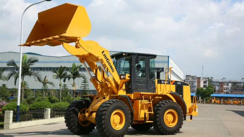
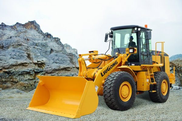
Фронтальный погрузчик LiuGong CLG 842
LiuGong CLG 842 – фронтальный погрузчик от китайского производителя, рассчитанный на большие нагрузки. Перед нами полноразмерная версия популярной модели, которая пользуется высоким спросом во многих странах мира, преимущественно в СНГ и евразийском регионе. Техника получила сбалансированные технические и ездовые возможности, рассмотренные в этой статье. То же самое касается и возможностей машины. Рассматриваемый аппарат не только успешно прошел все заводские испытания, но и заслужил позитивное мнение со стороны пользователей. Такая машина пригодиться для нужд профессиональных организаций, строительных корпораций, а также подойдет для частных предпринимателей, которым нужен производительный и недорогой погрузчик.
Назначение
Люгонг CLG 842 – высокотехнологичный и автопогрузчик, изготовленный из надежных и прочных компонентов. Он предназначен для работы в дорожном и сельском хозяйстве, а также пользуется высоким спросом у жилищно-коммунальных структур. В частности, возможности данной модели можно оценить в землеройных операциях – например, при выкапывании и замене сточных и канализационных труб. Также китайская машина идеально подойдет для ямочного ремонта дорог, строительства новых пешеходных тротуаров и автомобильных трасс, площадей и парковочных зон. Техника превосходно себя зарекомендовала и в качестве погрузчика и транспортировщика грузовой тары, в том числе и стратегически важных предметов для строительства. Имея необходимое оборудование, представленное ниже, автопогрузчик CLG 842 сможет выполнить любые задачи.
Видео
Навесное оборудование
- Отвал снеговой – приспособление, без которого не обойтись в зимнее время года, при наличии больших снегопадов и экстремально низких температур. Данное оборудование эффективно очищает дороги и тротуары от слежавшегося и свежевыпавшего снега. В механической версии отвал регулируется вручную, а модификация с гидравлическим приводом настраивается с помощью рычага, расположенного в водительской кабине. Таким образом, в этом случае оператору не придется выходить из кабины, чтобы отрегулировать угол наклона отвала.
- Вилы паллетные – устройство, предназначенное для погрузки и транспортировки грузовой тары, которая располагается на поддонах. В частности, речь идет о легко бьющихся грузах, стеклянной таре и других хрупких предметах. Благодаря этой опции машина приобретает возможности вилочного погрузчика.
- Стрела телескопическая – навесное оборудование для подъема и перемещения грузовой тары, масса которой может достигать двух тонн. В комплектацию входит крановый крюк, закрепленный на шарнирной опоре. Данная опора, в свою очередь, позволяет крюку вращаться в разных плоскостях.
- Бревнозахват – грузоподъемная конструкция, рассчитанная на работу с грузами массой от 3 до 5 тонн в зависимости от модификации. Представляет собой прижимное устройство с захватом, который удерживает цилиндрические предметы (бревна, трубы, столбы, сваи) таким образом, чтобы они не вывалились в процессе перевозки. В бревнозахвате используется современная технология производства гидравлических шлангов, обеспечивающая устойчивость работы при высоком давлении в гидравлической системе.
- Ковш фронтальный – универсальное приспособление для фронтальных погрузчиков. Устанавливается спереди, и предназначается для погрузки и перевозки мусора, снега и сыпучих материалов.
- Ковш снегоуборочный – это навесное устройство отличается удобством пользования даже при работе с большими объемами снега. Данная опция рассчитана на уборку свежевыпавшего и слежавшегося снега, в том числе обледенелых и твердых сугробов. Прочность конструкции ковша обусловлена материалом изготовления – это толстая и прочная сталь, устойчивая к повреждениям при наезде на твердые предметы. Эргономичные крепления ковша позволяют его быстро установить или демонтировать на погрузчик.
- Отвал бульдозерный – устройство, вместе с которым фронтальный автопогрузчик Люгонг CLG 835 приобретает способности мини-бульдозера. Опция оснащена поворотной функцией, которая отвечает за возможность настройки угла поворота отвала относительной передней оси погрузчика. Таким образом, можно выбирать траекторию выбрасывания снега, песка или грунта – вперед, либо в правую и переднюю стороны.
- Ковш челюстной – устройство в виде двух «лопастей», смыкающихся друг с другом более плотного и надежного удержания груза, чтобы он не высыпался наружу. Благоадря этому челюстной ковш отлично подходит для перевозки сыпучих материалов.
- Щетка – опция для коммунального хозяйства, востребованная в жилищно-коммунальных сферах деятельности. Основной спектр задач – уборка и расчистка территорий от свежевыпавшего снега, сметание пыли, мусора и листвы с тротуаров и вдоль проезжих частей. В зависимости от исполнения щетки бывают дорожные, поворотные, а также промышленные щетки с бункером.
- Вилы с прижимом/с захватом – сельскохозяйственная опция для работы с волокнистыми материалами. Захват обеспечивает быструю и эффективную погрузку сена, взрыхленного сенажа, скошенной травы и других подобных материалов с плотностью не больше 800 кг на 1 куб. м. К тому же, во время транспортировки груз не высыпается наружу, и остается внутри вил.
- Люлька – подъемное приспособление, являющееся альтернативой подъемному крану. Представляет собой компактную подъемную платформу, которая занимает минимум места, что позволяет ее использовать практически повсеместно, даже в закрытых складских помещениях, внутри зданий и сооружений. Используется в основном для работы на высоте. Безусловно, с помощью люльки можно работать и на улице – например, устанавливать осветительные плафоны и высоковольтные провода. Помимо этого, можно выполнять отделку и покраску потолков, фасадов зданий и т. д.
- Адаптер ковша – аксессуар для более надежного крепления тяжелого навесного оборудования с большой грузоподъемностью. Например, с помощью адаптера можно закрепить ковш.
Особенности устройства и эксплуатации
- Модель Люгонг CLG 842 получила следующие модификации:
- Версия 842 II, которая от базовой модели отличается более мощным мотором, наличием усовершенствованной КПП от компании ZF.
- Вариант CLG 842 III, выделяющийся еще более производительным двигателем. В отличие от предыдущей версии мощностью 129 кВт, данный агрегат развивает 144 кВт.
- CLG 842 III Tool Carrier – специализированный погрузчик для работы в карьерных условиях. У этой машины мощность двигателя может быть форсирована выше 145 кВт.
- GLC 842 III Tool Carrier – усовершенствованная модификация с улучшенными прочностными характеристиками, рассчитанная на увеличенный объем нагрузок. Имеет длительный межсервисный интервал и изготовлена из долговечных комплектующих. Оснащается 144-киловаттным двигателем.
- CLG 842 IV – данный погрузчик практически не отличается от предыдущего варианта, за исключением более мощного 150-киловаттного мотора.
- Стандартная модель CLG 842 оснащается силовым агрегатом мощностью 123 кВт. Этой силовой отдачи достаточно для продолжительного рабочего цикла в течение 14 секунд. Максимальное усилие на отрыв при этом достигает 125 кН, а эксплуатационная масса составляет 13 700 кг. Стандартный ковш имеет полезную площадь для погрузки, которая составляет 2,3 куб. м. В переводе на лошадиные силы базовый мотор развивает 167 л. с. Он отличается низким уровнем шумов и вибраций – благодаря дополнительной звукоизоляции. В комплектацию также входят различные импортные детали, такие как немецкий фильтр для очистки горючего Separ-2000. Помимо этого, уже в стандартном наборе есть подогреватель и специальная емкость, в которой накапливается влага. По сути, система фильтрации имеет несколько уровней очистки топлива, которое тщательно фильтруется еще до того, как попадет в камеру сгорания. Безусловно, это благоприятно сказалось на надежности ДВС.
- Автопогрузчик Люгонг 842 получил рамный каркас с гидравлическим приводом. Каркас соединен шарнирными опорами, которые придают конструкции высокую прочность. Среди базовых элементов оснащения также присутствует полуавтоматический мост ZF.
- Люгонг CLG 842 оснащается многофункциональной кабиной, которая в плане оснащения не уступает более именитым зарубежным аналогам. В частности, обратим внимание на следующие особенности кабины, а также установленные опции:
- Системы безопасности ROPS и FOPS, обеспечивающие дополнительную защиту оператора в случае попадания твердых предметов, перевертыша погрузчика или перегрузки навесного оборудования.
- Встроенная система отопления салона, с функцией регулировки температуры. Также есть кондиционер, обеспечивающий комфорт и уют в кабине в экстремально жарких условиях.
- Наличие дополнительных бардачков для хранения крупных и мелких вещей, что весьма практично и удобно.
- CD-магнитола входит в базовую комплектацию.
- Кресло от компании Grammer. Его можно регулировать по своему усмотрению, подгонять под себя в зависимости от роста и пропорций тела оператора. Также можно настраивать и рулевую колонку.
- Широкая площадь остекления, обеспечивающая хорошую 360-градусную видимость. Обзор из салона нисколько не затруднен, даже не смотря на затемненные стекла, которые защищают оператора от ультрафиолетовых лучей, что особенно актуально жарким летом.
- Цельная крышка капота.
- Рулевой диск с возможностью регулировки.
- Полноразмерный комплект инструментов, помещенный в специальную нишу. Его можно возить с собой.
- Гидравлическая система – от японской компании Kawasaki. Она хорошо себя зарекомендовала во всех моделях компании Люгонг. Гидравлика обеспечивает легкое и надежное управление погрузчиком, а прочность всех узлов и компонентов гидросистемы при этом находится на высоком уровне. К тому же, хорошей управляемости способствуют двойные гидроцилиндры. Что касается ходовой части, она также разработана инженерами фирмы ZF. Максимальная скорость автопогрузчика Люгонг CLG 842 составляет 41 км/час на максимальной четвертой передней передаче. При этом вторая задняя передача позволяет достигать 12 км/час. При движении назад скорость на первой передаче составляет 7 км/час. Наилучшая топливная экономичность достигается при спокойной манере вождения. Тормозная система – также от компании Kawasaki. Пневматические тормоза – гидравлические, с двумя контурами. В зависимости от модификации можно выбрать сухие или мокрые дисковые тормоза, работающие в масляной ванне.
Технические характеристики
- Масса/объем ковша – 13,7 тонн/2.3 куб. м.
- Грузоподъемность – 4 тонны
- Усилие резания ковшом – 125 кН
- Высота выгрузки – 2800 мм
- Радиус поворота с учетом внешней стороны ковша – 6405 мм
- Угол поворота – 38 градусов
- Коробка передач – ZF 4WG200
- Коробка передач – механическая, с 4 передними и 3 задними скоростями
- Скорость при движении вперед – 41 км/час (максимальная)
- Скорость при движении назад – 26 км/час (максимальная)
- Время подъема ковша под нагрузкой – 10.4 секунды
- Время опускания пустого ковша – 3,7 секунды
- Давление в гидравлической системе – 18 Мпа
- Вместимость бака с топливом – 254 л
- Вместимость гидробака – 230 л
- Параметры шин – 20,5-25
- Гидравлическая тормозная система – да
- Тип рулевого механизма – шарниры, сочлененная рама, гидропривод
- Стандартный рабочий орган – ковш.
Цена
Средняя стоимость фронтального автопогрузчика Люгонг CLG 842 в новом состоянии составляет 2,6 миллиона рублей. Версия в поддержанном состоянии обойдется в пределах 2 млн рублей.

-
Contents
-
Table of Contents
-
Troubleshooting
-
Bookmarks
Quick Links
201701001
CLG835H
WHEEL LOADER
SERVICE MANUAL
Applicable type and model: CLG835H PERKINS Engine 1204F-E44AT/ LIUGONG Wet Axle/ ZF
4WG158 Gearbox
Related Manuals for LiuGong CLG835H

Summary of Contents for LiuGong CLG835H
-
Page 1
201701001 CLG835H WHEEL LOADER SERVICE MANUAL Applicable type and model: CLG835H PERKINS Engine 1204F-E44AT/ LIUGONG Wet Axle/ ZF 4WG158 Gearbox… -
Page 3: Table Of Contents
Contents January 24, 2017 CLG835H Contents General Information ………………….1-1 Power System ……………………2-1 Power Train System ………………….3-1 Hydraulic System ………………….4-1 Air Conditioning System………………..5-1 Driver’s Cab System………………….6-1 Structure………………………7-1 Electrical System………………….8-1 Appendix ……………………..9-1…
-
Page 4
Contents January 24, 2017 CLG835H… -
Page 5: General Information
General Information January 24, 2017 CLG835H General Information How to Use the Manual ………………..1-3 Safety description ………………….1-4 Identification of Complete Machine and System…………1-5 Engine Identification …………………..1-6 Cable Code Identification ………………..1-8 Coating Materials………………….1-10 Weight Table ……………………1-12 Unit conversion table ………………..1-14 Standard Torque Table ………………..1-15 Oils use specifications………………..1-18…
-
Page 6
General Information January 24, 2017 CLG835H… -
Page 7: How To Use The Manual
Technical manuals are divided in several parts : tion, please consult the dealer of LiuGong in repair and test . Repair sections tell how to repair local area or Service Department of LiuGong the components.
-
Page 8
If these hazard complete and most current information before warnings are not heeded, bodily injury or death starting any job. LiuGong has the most current could occur to you or other persons. information available. -
Page 9
Product Serial Number Identification Choosing the Correct Supporting Manuals The product identification number (PIN) plate is LiuGong wheel loaders are available in different located on left side of machine front frame under machine configurations based on the various the pin of boom . Each machine has a 17- char- markets into which they are sold. -
Page 10: Engine Identification
Engine Identification January 24, 2017 CLG835H Figure 2 Pin Plate (17-character with CE mark) P11000002 Engine Identification The engine serial number plate is located on the right side of engine model 1204F. Each engine has two engine numbers (LIST NO. and SERIAL NO.) shown on this plate.
-
Page 11
January 24, 2017 Engine Identification CLG835H Figure 3 Engine Serial Number Plate Location P11000003 Figure 4 Engine Serial Number Plate P11000004… -
Page 12: Cable Code Identification
Cable Code Identification January 24, 2017 CLG835H Cable Code Identification The wire in circuit diagram is marked in combination with wire No., wire categories, color abbreviation codes and wire gauge for maintenance. For example: P28E00002 Wire No. Wire No. is digital code for marking wire with three Arabic numbers in accordance with certain rules.
-
Page 13
January 24, 2017 Cable Code Identification CLG835H Color English Abbreviation Color English Abbreviation Violet VIOLET Orange ORANGE White WHITE Light blue LIGHT BLUE LTBU Red/green RED/GREEN RD/GN Yellow/blue YELLOW/BLUE YL/BU Remarks: The code composed of 2 colors indicates double-color wire For example: «RD/GN»… -
Page 14: Coating Materials
1-10 Coating Materials January 24, 2017 CLG835H Coating Materials Name Specification Main features and purposes 1277 Thread locker seal- ● Features: anaerobic and fast air drying 1277 ants ● Purposes: used for parts not frequently removed 1243 Thread locking seal-…
-
Page 15
1-11 January 24, 2017 Coating Materials CLG835H Items Indicator Testing method Remarks Use single cutting edge or scriber to perform the cross cut on the paint film Approval standard: No with five horizontal and vertical lines. the whole piece of grid… -
Page 16: Weight Table
1-12 Weight Table January 24, 2017 CLG835H Weight Table The following table indicates the reference value of the weight of each component. When using the lifting equipment , please refer to the following table to select the sling. Component Weight (kg)
-
Page 17: Unit Conversion Table
1-13 January 24, 2017 Unit Conversion Table CLG835H Unit Conversion Table The Manual uses ISO International System of Units, and ISO international units are converted into Brit- ish units as shown in following figure: Parameters Metric unit British unit Multiple 0.03937…
-
Page 18: Standard Torque Table
1-14 Standard Torque Table January 24, 2017 CLG835H Standard Torque Table TORQUE SPECIFICATIONS – METRIC HARDWARE Use the following torques when specifications are not given. These values apply to fasteners with coarse threads as received from supplier, plated or unplated, or when lubricated with engine oil, These values do not apply if graphite or Moly disulfide grease or oil is used.
-
Page 19
1-15 January 24, 2017 Standard Torque Table CLG835H Tightening torque of 24° cone O-ring sealed hose connector Tightening torque Hose inner diame- Series Thread size ter mm kgf.m M12×1.5 16±1 1.6±0.1 M14×1.5 16±1 1.6±0.1 M16×1.5 26±2 2.7±0.2 M18×1.5 37±2 3.8±0.2 M22×1.5… -
Page 20
1-16 Standard Torque Table January 24, 2017 CLG835H Tightening torque Bolt performance Series Bolt level kgf.m 25.2±1.2 2.57±0.12 52.5±2.5 5.35±0.25 96.6±4.6 9.85±0.47 220±10 22.5±1.07 420±20 42.8±2.0 Heavy type 33.6±1.6 3.42±0.16 73.5±3.5 7.5±0.35 10.9 136±6 12.8±0.6 310±15 31.6±1.5 577±27 58.9±2.8 Tightening torque of thread angle type sealed hose connector… -
Page 21: Oils Use Specifications
Tightening torque Thread size kgf.m 24±2 2.4±0.2 30±2 3.1±0.2 30±2 3.1±0.2 30±2 3.1±0.2 Oils use specifications Fluids and lubricants for CLG835H-T4F Category Name Capacity Application parts Remarks ★ SAE 15W/40 CJ-4 ≥-10°C(14°F) 12L Engine oil Diesel engine 3 US gal ≤-10°C(14°F)
-
Page 22
1-18 Oils use specifications January 24, 2017 CLG835H NOTE 1 : DO NOT use an alternate oil in the axle , the transmission box ,the engine . the parts could be damaged as a result of using an alternate oil. -
Page 23
1-19 January 24, 2017 Oils use specifications CLG835H MAINTENANCE SCHEDULE FREQUENCY IN HOURS SERVICE SERVICE POINTS INTERVAL Radiator Coolant Level ★ ★ Tires Hydraulic Filter ★ As Required ★ ★ Air Cleaner Alternator , AC ,Drive Belt ★ ★ Fire Extinguisher… -
Page 24
1-20 Oils use specifications January 24, 2017 CLG835H FREQUENCY IN HOURS SERVICE SERVICE POINTS INTERVAL Replace Hydraulic Oil Filter 1000 Replace Pilot Hydraulic Oil Filter 1000 Change Front & Rear Axle Oil 1000 Replace Cab Fresh Air Filter 1000 Every 1000… -
Page 25: Technical Specification Of The Complete Machine
Do not use the environments. machine beyond the stipulated application scope, Guangxi LiuGong Machinery Co., Ltd Requirements of Work Environments will not bear any safety liability, and these safety liabilities will be born by users. Under 1.
-
Page 26
1-22 Technical Specification of the Machine January 24, 2017 CLG835H Main Components FRONT RIGHT LEFT REAR 1. Bucket 6. Cab 11. Front frame 16. Engine hood 2. Rocker arm 7. Rear fender 12. Front fender 17. Rear combination lights 3. Bucket cylinder 8. -
Page 27
1-23 January 24, 2017 Technical Specification of the Machine CLG835H Performance Parameters All rated lift capacities are based on the criteria of the machine being leveled on a hard and flat ground. When the machine is operated in conditions that deviate from these criteria (e. g. on soft or uneven ground, on a slope or when subject to slide loads), these conditions shall be taken into account by the operator. -
Page 28
1-24 Technical Specification of the Machine January 24, 2017 CLG835H Machine Specifications CLG835H T4f Item Unit Quick coupler Pin On Rated load weight kg (lb) 3000 (6615) 3000 (6615) Rated power 97.9 97.9 Operating mass kg (lb) 11200 (24696) 10800 (23814) -
Page 29
Number of gears gears Operating pressure of shift oil pump 1.6~1.8MPa (232~261psi) (gear pump) Manufacturer LiuGong Model LiuGong 3T wet-type axle Type Wet-type alxe Drive axle Max. traction force 100kN (22480lbf) Front & rear axle reduction ratio 20.2656 Rear axle swing angle 12°… -
Page 30
1-26 Technical Specification of the Machine January 24, 2017 CLG835H Main Components Specifications System pressure Mpa (psi) 19 (2755) Control valve Three spools System flow L/min (US gpm) 210 (55.48) Lifting time (full load) Dumping time Float lowering time Total time… -
Page 31
Note: 1. Continuing improvement and advancement are made to LiuGong products. All the specifications are the latest product information obtainable at the time of publication. LiuGong will reserve the right to make change without notice. 2. The above parameters are the theoretical values, the tolerance ranges during testing are provided by LiuGong… -
Page 32
1-28 Machine Inspection Table January 24, 2017 CLG835H Machine Inspection Table Inspec- Inspection method and acceptance criteria tion item Complete machine information: visual check the complete machine number for compliance with description of model Fastening bolt: visual check whether the left and right mounting bolts of front axle are tightened firmly in place;… -
Page 33
1-29 January 24, 2017 Machine Inspection Table CLG835H Inspec- Inspection method and acceptance criteria tion item Horn: press the horn button on the lever of the horn button/control lever on the combination Climbing up lever horn button/steering wheel and listen, no abnormal sound and failure to the horn should… -
Page 34
1-30 Machine Inspection Table January 24, 2017 CLG835H Inspec- Inspection method and acceptance criteria tion item Ride control (option): park the machine on the level ground, disconnect the ride control system button, jack up the shovel head; after 5 seconds, connect the ride control system button, and the boom shall perform automatic lowering operation. -
Page 35
1-31 January 24, 2017 Machine Inspection Table CLG835H Inspec- Inspection method and acceptance criteria tion item Backup alarm: when the shift lever is placed at reverse, the reverse alarm begins to perform buzzing alarm immediately. Brake system: Drive the vehicle for 10 laps, during which depress the brake pedal and the com- plete machine is braked, two times per lap;… -
Page 36
1-32 Machine Inspection Table January 24, 2017 CLG835H Inspec- Inspection method and acceptance criteria tion item Visual check: gap of lapped surface at hinge between boom and frame, oil cylinder, rocker and tie rod light is ≤1mm Touch: there is no oil leakage at big cavity and small cavity pipe and joint of left and right boom oil cylinder pipeline;… -
Page 37
1-33 January 24, 2017 Machine Inspection Table CLG835H Inspec- Inspection method and acceptance criteria tion item Visual check: there is no interference between hydraulic oil tank and cab; there is no interfer- ence between left and right hydraulic oil tank guard, foot pedal and driver Visual check: diesel engine mounting bolt is fastened and there is no oil leakage at parts on left side and oil pan;… -
Page 38
1-34 Machine Inspection Table January 24, 2017 CLG835H… -
Page 39: Power System
Power System January 24, 2017 CLG835H Power System Basic Information ………………….2-3 Safety …………………………2-3 Overview-components and position …………………..2-5 System technical parameters…………………….2-9 Universal tool, tooling list ……………………2-10 Structure Function Principle ………………2-11 Engine system ………………………..2-11 Overview ……………………….2-11 Diesel engine ………………………2-12 Intake and exhaust system ……………………2-25 Intake and exhaust assembly………………….2-25…
-
Page 40
Power System January 24, 2017 CLG877H Removal and installation of radiator…………………2-91 Disassembly and assembly of radiator ………………..2-100 Removal and installation of fan ………………….2-106 Removal and installation of fuel tank ………………..2-111 Removal and installation of fuel radiator ………………..2-115 Fault Diagnosis and Troubleshooting ……………2-118 Precautions for fault diagnosis ………………….2-118 Common fault code and troubleshooting ……………….2-118… -
Page 41: Basic Information
January 24, 2017 Basic Information CLG835H Safety Basic Information Preventing Burns After running for some time, parts of the machine Safety will be hot,such as, engine, DPF (Diesel Particulate Filter) and inter-cooler steel pipe, those parts which are cooled down later shall be Compressed Air inspected or repaired.
-
Page 42
Basic Information January 24, 2017 Safety CLG835H Fuel leaking onto the hot surface or electrical ● elements may cause fire. Do not smoke when refilling or within refiling ● area, and in the place storing flammables. P11000157 Store the fuel, lubricant into containers with ●… -
Page 43: Overview-Components And Position
January 24, 2017 Basic Information CLG835H Overview-components and position Overview-components and position Components and position Power system has the function of converting chemical energy of fuel into mechanical energy to be sup- plied to the machine. Power system includes engine system, radiator system and fuel tank assembly.
-
Page 44
Basic Information January 24, 2017 Overview-components and position CLG835H Position figure of power system in the machine P18P00007 1. Engine system 2. Cooling system 3. Fuel tank assembly… -
Page 45
January 24, 2017 Basic Information CLG835H Overview-components and position Components of power system P18P00008 1. Diesel particle filter DOC 3. DEF pump 5. Radiator mounting assembly 2. Diesel engine 4. DEF tank 6. Oil-water separator… -
Page 46
Basic Information January 24, 2017 Overview-components and position CLG835H Components of power system P18P00009 7. Air filter 9. Oil drain device 11.Diesel particle filter SCR 8. Fuel fine filter 10.Solenoid water valve 12.Exhaust pipe… -
Page 47: System Technical Parameters
January 24, 2017 Basic Information CLG835H System technical parameters System technical parameters Model Perkins 1204F-E44AT Type In line-four cylinders, four-stroke, turbocharged Emission EPA Tier4 Final *Rated power 97.9kW/2200r/min(133.144PS/2200rpm) Engine *Maximum idling speed 2376±50rpm *Minimum idling speed 800±50rpm Engine oil level 7.7L (2.03434USgal)
-
Page 48: Universal Tool, Tooling List
2-10 Basic Information January 24, 2017 Universal tool, tooling list CLG835H Universal tool, tooling list Precautions on removal and installation: 1. Assembly and disassembly must be carried out when engine is cool. In general, open Name Specification engine hood after engine is shut down, and…
-
Page 49: Structure Function Principle
2-11 January 24, 2017 Structure Function Principle CLG835H Engine system Structure Function Principle Engine system Overview Components and position The diesel engine mounting assembly is composed of diesel engine, bracket and shock absorber. P18P00009 1. Diesel engine 2. Bracket 3. Shock absorber Working principle description Engine mounting as has the function of realizing effective installation of engine.
-
Page 50: Diesel Engine
2-12 Structure Function Principle January 24, 2017 Engine system CLG835H 3. Impact generated by uneven roads can be effectively isolated from being transferred to engine through engine mounting, and influence of road impact on engine is reduced. Diesel engine Technical parameters…
-
Page 51
2-13 January 24, 2017 Structure Function Principle CLG835H Engine system Part Structure and Principle Introduction External view of Perkins engine 1204F-E44TA P18P00010 1. Front lifting eye 6. Pnmiog/trarferfuel pump 11.Oil sampling vafve 2. Crankcase breather 7. In line fuel fitier 12.High-pressure fuel pump… -
Page 52
2-14 Structure Function Principle January 24, 2017 Engine system CLG835H P18P00012 14.Air intake 16.Water pump 18.Tensioner 15.Coolant outlet 17.Coolant intake 19.Belt… -
Page 53
2-15 January 24, 2017 Structure Function Principle CLG835H Engine system P18P00012 20.B ac k pressure valve 25.Starter so l enoid 30.Flywheel housing 21.Htgh-pressure turtoocharger 26.Starting motor 31.NOx reduction cooler 22.Low-pressure turbocharger 27.Starter relay 32.Rear lifting eye 23.Alternator 28.Oil dram tap 24.Refrigerant compressor… -
Page 54
2-16 Structure Function Principle January 24, 2017 Engine system CLG835H The diesel engine is generally composed of two major mechanisms and four systems: Engine body and cylinder head Crank rod connection mechanism Air distribution mechanism Diesel engine Cooling system Lubrication system… -
Page 55
2-17 January 24, 2017 Structure Function Principle CLG835H Engine system It is located at top of cylinder block, and used for sealing the cylinder head, and forms a com- bustion chamber together with cylinder and piston. It is usually Cylinder head… -
Page 56
2-18 Structure Function Principle January 24, 2017 Engine system CLG835H It is composed of piston, piston ring and piston pin. Piston: piston head is a part of Piston group combustion chamber, with the shape of dome head, flat head, crown head 1. -
Page 57
2-19 January 24, 2017 Structure Function Principle CLG835H Engine system It is composed of crankshaft, fly- Crankshaft fly- wheel and torsion damper wheel group P18P00020 It is composed of valve group and valve train, and mainly used for controlling the intake/… -
Page 58
2-20 Structure Function Principle January 24, 2017 Engine system CLG835H It is composed of valve, valve guide, valve seat ring, valve Valve group spring, valve rotating mecha- nism 1. Valve guide pipe 3. Valve spring 2. Valve 4. Valve seat ring P18P00022 1. -
Page 59
2-21 January 24, 2017 Structure Function Principle CLG835H Engine system It is used for increasing the pressure of cooling water to accelerate the cycle of cooling Water pump water in the cooling system to enhance the heat radiating abil- P18P00024… -
Page 60
2-22 Structure Function Principle January 24, 2017 Engine system CLG835H It is composed of fuel coarse fil- ter (oil-water separator),fuel delivery pump,fuel fine filter,fuel injection pump,injector,fuel pipe Fuel system and combustion chamber,and used for supplying fuel to engine. It is used for filtering the larger… -
Page 61
2-23 January 24, 2017 Structure Function Principle CLG835H Engine system P18P00029 It is used for charging the bat- tery when the engine operates to ensure that the battery can Alternator provide high enough voltage during the engine cranking P18P00030 It pushes the turbo to drive the… -
Page 62: Intake And Exhaust System
2-24 Structure Function Principle January 24, 2017 Intake and exhaust system CLG835H Intake and exhaust system Intake and exhaust assembly Components and position Intake and exhaust assembly consists of air pre-filter, air filter, diesel oxidation catalyst (DOC), selective catalytic reducer (SCR) and exhaust pipe.
-
Page 63
2-25 January 24, 2017 Structure Function Principle CLG835H Intake and exhaust system Working principle of the intake and exhaust assembly: air is taken in through air pre-filter. There are rotating blades inside the air pre-filter, which can discharge big dust in intake air from the bottom of air pre-filter. -
Page 64
2-26 Structure Function Principle January 24, 2017 Intake and exhaust system CLG835H Exhaust path figure of engine: Cold gas Hot gas P18P00034 1. Turbocharger 2. Diesel oxidation catalyst DOC 3. Selective catalytic reducer SCR… -
Page 65: Air Filter
2-27 January 24, 2017 Structure Function Principle CLG835H Intake and exhaust system Air filter Technical parameters P18P00035…
-
Page 66
Structure Function Principle January 24, 2017 Intake and exhaust system CLG835H Part Structure and Principle Introduction The air filter is composed of housing, main filter,safety filter and end cover. Air filter ensures clean and dry air to enter engine through main filter element and safety filter element. When engine operates, air… -
Page 67: Diesel Particle Filter System
2-29 January 24, 2017 Structure Function Principle CLG835H Diesel Particle Filter System Diesel Particle Filter System Part Structure and Principle Introduction The main function of DPF (Diesel Particle Filter) is to reduce the harmful substance of engine exhaust in order to conform with emission standard. Particulates and NOx emission of the model conform with the emission standard of Tier 4Final/Euro Stage IV.
-
Page 68: Def Pipeline Assembly
2-30 Structure Function Principle January 24, 2017 DEF pipeline assembly CLG835H DEF pipeline assembly Components and position DEF pipe-line assembly includes DEF tank, DEF pump, DEF pipe-line and water way. P18P00039 1. DEF tank 3. DEF pipe-line 2. DEF pump…
-
Page 69
2-31 January 24, 2017 Structure Function Principle CLG835H DEF pipeline assembly Description of principle diagram and working principle The function of DEF pipe-line is to provide appropriate amounts of DEF for DPF (Diesel Particle Filter) system in order to reduce nitride oxides content of exhaust. DEF is pumped to DEF pump from DEF tank via outlet pipe and then transported to injector via pressure pipe. -
Page 70: Def Tank
January 24, 2017 DEF pipeline assembly CLG835H Water way is used to transfer engine coolant to DEF tank and heat the DEF solution avoiding the crystal- lization. When urea temperature is less than -8°C(17.6°F), the solenoid water valve of water way opens, and engine coolant enters into urea tank to prevent urea solution from freeze, however, when urea tem- perature exceeds 5°C(41°F), the solenoid water valve of water way closes to prevent urea solution from…
-
Page 71
2-33 January 24, 2017 Structure Function Principle CLG835H DEF pipeline assembly Part Structure and Principle Introduction The function of DEF tank is to store DEF solution and provide DEF for DPF (Diesel Particle Filter) during the machine operates. DEF tank consists of shell, multi-functional head unit and cover. There are three sensors in the multi-functional head unit: temperature sensor, liquid level sensor and quality sensor. -
Page 72
2-34 Structure Function Principle January 24, 2017 DEF pipeline assembly CLG835H Multi-functional head unit Electrical connection flying lead — 375 mm long P18P00043 1. DEF level and temp sensor assembly 4. DEF outlet 7. DEF inlet 2. DEF tank heating tube (engine coolant flow 5. -
Page 73: Def Pump
2-35 January 24, 2017 Structure Function Principle CLG835H DEF pipeline assembly DEF pump Part Structure and Principle Introduction Urea pump will pump urea solution from urea tank, and the urea solution is transported to the nozzle of diesel particle filter after filtering.
-
Page 74
2-36 Structure Function Principle January 24, 2017 DEF pipeline assembly CLG835H P18P00045 1. Protection shield 2. Strainer assembly 3. Housing… -
Page 75: Cooling System
2-37 January 24, 2017 Structure Function Principle CLG835H Cooling system Cooling system Overview Components and position The radiator system is composed of radiator mounting, radiator pipe and oil drain device. P18P00046 1. Radiator mounting 2. Radiator pipe 3. Oil drain device…
-
Page 76
Structure Function Principle January 24, 2017 Cooling system CLG835H Description of principle diagram and working principle Cooling system comprises a radiator and corresponding connecting lines, where the radiator is com- posed of a water radiator, an air-air intercooler, a hydraulic oil radiator and a torque converter oil radiator. -
Page 77
2-39 January 24, 2017 Structure Function Principle CLG835H Cooling system Cooling system of this machine adopts hydraulic to drive fan and adopts suction mode to cool. The system adopts forced closed circulating water cooling system. Working principle of system is as follows:… -
Page 78
2-40 Structure Function Principle January 24, 2017 Cooling system CLG835H Air-air intercooler radiator Air-air intercooler has the main function of cooling high-temperature high-pressure gas across turbocharger and reducing temperature of air entering engine combustion chamber to increase air density. Its working principle is shown in Fig. below. After air is pressurized by turbocharger, temperature… -
Page 79
2-41 January 24, 2017 Structure Function Principle CLG835H Cooling system The air-air inter cooler radiating system of the vehicle arranged as the drawing below. P18P00050 1. Air-air intercooler 2. Turbocharger Hydraulic oil radiator Hydraulic oil radiator has the main function of radiating heat generated by hydraulic oil during the work-… -
Page 80: Radiator Group
Structure Function Principle January 24, 2017 Cooling system CLG835H Torque converter oil radiator Torque converter oil radiator has the main function of radiating heat generated by torque converter oil during the working of transmission and torque converter to avoid temperature of torque converter and transmission from being too high and ensure normal working of machine.
-
Page 81
2-43 January 24, 2017 Structure Function Principle CLG835H Cooling system Part Structure The radiator assembly is composed of air-air intercooler, water radiator, hydraulic oil radiator and torque converter oil radiator. P18P00052 1. Water radiator 3. Air-air intercooler 2. Hydraulic oil radiator… -
Page 82: Fan
2-44 Structure Function Principle January 24, 2017 Cooling system CLG835H 6. Slowly open auxiliary tank cover (wait until engine coolant temperature drops to be below 50°C122°F), slowly add coolant until Technical parameters coolant level is within 1 cm higher than well-…
-
Page 83: Fuel System
2-45 January 24, 2017 Structure Function Principle CLG835H Fuel System Fuel System Fuel Tank Assembly Technical parameters Effective volume 193L (50.9906USgal) Part Structure and Principle Introduction The fuel tank assembly is mainly composed of fuel tank, filler pipe, breather pipe, fuel tank cover.
-
Page 84: Fuel Lines
2-46 Structure Function Principle January 24, 2017 Fuel System CLG835H Fuel Lines Overview-components and position The fuel line is composed of fuel hose, fuel filter and fuel radiator. P18P00057 1. Fuel radiator 3. Fuel hose 2. Oil-water separator 4. Fuel pump…
-
Page 85
2-47 January 24, 2017 Structure Function Principle CLG835H Fuel System Description of principle diagram and working principle P18P00058 1. Fuel tank 3. Oil transfer pump 5. Oil-water separator 2. Fuel filter 4. High-pressure fuel pump 6. Fuel radiator Fuel system acts to provide engine with clean and sufficient fuel, which thus ensures proper operation of engine. -
Page 86
2-48 Removal and Installation January 24, 2017 Removal and installation of diesel engine CLG835H Removal and Installation Removal and installation of diesel engine Removal Figures Contents Tools 1. Turn off the negative elec- trode switch, and hang on a «No operating» warning board. -
Page 87
2-49 January 24, 2017 Removal and Installation CLG835H Removal and installation of diesel engine Figures Contents Tools 1. Remove the engine hood top cover according to removal and installation requirements and steps of engine hood. 2. Remove air filter according… -
Page 88
2-50 Removal and Installation January 24, 2017 Removal and installation of diesel engine CLG835H Figures Contents Tools 7. Unscrew the fuel pipe joint screw connected to the die- sel engine fuel pump with wrench. Remove the screw, seal gasket and keep them Tool: in a plastic bag. -
Page 89
2-51 January 24, 2017 Removal and Installation CLG835H Removal and installation of diesel engine Figures Contents Tools 10. Unscrew the clamp at the connection of water inlet pipe, outlet pipe and engine, unplug the water inlet pipe, outlet pipe and seal every… -
Page 90
2-52 Removal and Installation January 24, 2017 Removal and installation of diesel engine CLG835H Figures Contents Tools 12. Unscrew the 4 bolts on the heat insulation bracket, and tilt it to the radiator direction by an angle to avoid interfer- ence when lifting the engine. -
Page 91
2-53 January 24, 2017 Removal and Installation CLG835H Removal and installation of diesel engine Figures Contents Tools 14. Remove captive bolts on connecting surface of engine and torque con- verter & engine flywheel according to removal and installation requirements and steps of transmission &… -
Page 92
2-54 Removal and Installation January 24, 2017 Removal and installation of diesel engine CLG835H Figures Contents Tools 16. Operate wire rope on travel- Lifting hole ing crane for lifting hook to pass hook through lifting hole at pulley side of engine, and lift engine as slowly as possible. -
Page 93
2-55 January 24, 2017 Removal and Installation CLG835H Removal and installation of diesel engine Figures Contents Tools 18. Slowly operate traveling crane and hold both sides of engine in order to ensure that engine is slowly and steadily lifted out of com-… -
Page 94
2-56 Removal and Installation January 24, 2017 Removal and installation of diesel engine CLG835H Installation Figures Contents Tools 1. Install engine mounting sup- port on engine with captive bolt for engine mounting support, and pre-tighten captive bolt with an open- end wrench. -
Page 95
2-57 January 24, 2017 Removal and Installation CLG835H Removal and installation of diesel engine Figures Contents Tools 4. Operate the traveling crane Lifting hole and put down the engine as slow as possible to match the engine surface and gearbox & torque converter assembly surface, and align the holes. -
Page 96
2-58 Removal and Installation January 24, 2017 Removal and installation of diesel engine CLG835H Figures Contents Tools 6. Crank the engine flywheel case to make the torque converter align with mount- Tool: ing threaded hole on the engine flywheel, screw and… -
Page 97
2-59 January 24, 2017 Removal and Installation CLG835H Removal and installation of diesel engine Figures Contents Tools 11. Push the heat-insulation bracket to installation posi- tion and tighten the 4 anchor bolts. Tool: P18P00080 12. Insert the water inlet pipe into hot water inlet of engine, then clamp it with a clamp. -
Page 98
2-60 Removal and Installation January 24, 2017 Removal and installation of diesel engine CLG835H Figures Contents Tools 13. Insert the water outlet pipe into water outlet of engine, the water inlet pipe into water inlet of engine, then clamp it with a clamp. -
Page 99
2-61 January 24, 2017 Removal and Installation CLG835H Removal and installation of diesel engine Figures Contents Tools 16. Fix the diesel joint on the engine fuel pump with screw and seal gasket. The pipe connected to the oil-water separator is fuel inlet pipe… -
Page 100
2-62 Removal and Installation January 24, 2017 Removal and installation of diesel engine CLG835H Figures Contents Tools 20. Install the air filter according to the installation steps of air filter described. 21. Install the engine hood according to installation steps of engine hood. -
Page 101
2-63 January 24, 2017 Removal and Installation CLG835H Removal and installation of air filter Removal and installation of air filter Removal Figures Contents Tools 1. Put out the harness connec- tor on the air filter, and seal every ports with plastic seal- ing membrane as required. -
Page 102
2-64 Removal and Installation January 24, 2017 Removal and installation of air filter CLG835H Figures Contents Tools 3. Loosen the bolts of the air fil- ter mounting plate with wrench, then remove the air filter with mounting plate. Tool: Open-end… -
Page 103
2-65 January 24, 2017 Removal and Installation CLG835H Removal and installation of air filter Installation Figures Contents Tools 1. Fix the air filter on the mounting plate with bolts. Tool: Open-end wrench 10# P18P00090 2. Install the air filter with the mounting plate on the heat insulation bracket. -
Page 104
2-66 Removal and Installation January 24, 2017 Disassembly and assembly of air filter CLG835H Figures Contents Tools 4. Install the blocking indicator of air filter on the air filter, and press the indicator end face to reset it. Tool: P18P00093 5. -
Page 105
2-67 January 24, 2017 Removal and Installation CLG835H Disassembly and assembly of air filter Figures Contents Tools 2. Take out the main filter ele- ment along the direction of housing. It can be taken out directly by hand, and then take out the main filter ele- ment by sequence. -
Page 106
2-68 Removal and Installation January 24, 2017 Disassembly and assembly of air filter CLG835H Assembly Figures Contents Tools 1. Use the handle of safety fil- ter element to make the filter element slide into the outlet side at an oblique angle and… -
Page 107
2-69 January 24, 2017 Removal and Installation CLG835H Removal and installation of DPF (Diesel Particle Filter) Removal and installation of DPF (Diesel Particle Filter) Removal Figures Contents Tools 1. Turn off the negative elec- trode switch, and hang on a «No operating»… -
Page 108
2-70 Removal and Installation January 24, 2017 Removal and installation of DPF (Diesel Particle Filter) CLG835H Figures Contents Tools 4. Remove the DEF(diesel exhaust fluid) pipe joint and electrical connector on the DOC. P18P00103 5. Unplug the exhaust pipe and… -
Page 109
2-71 January 24, 2017 Removal and Installation CLG835H Removal and installation of DPF (Diesel Particle Filter) Figures Contents Tools 7. Unscrew the captive bolts on one side bracket of SCR and lower the diesel particle fil- Tool: ter. Take care of the clamp… -
Page 110
2-72 Removal and Installation January 24, 2017 Removal and installation of DPF (Diesel Particle Filter) CLG835H Figures Contents Tools 3. Insert the exhaust pipe into SCR outlet port, tighten the clamp and U-clamp, and insert the electric connector. Tool: Open-end… -
Page 111
2-73 January 24, 2017 Removal and Installation CLG835H Removal and installation of DEF pump Removal and installation of DEF pump Removal Figures Contents Tools 1. Stop the vehicle, and turn off the negative electrode switch, and hang on a «No operating»… -
Page 112
2-74 Removal and Installation January 24, 2017 Removal and installation of DEF pump CLG835H Figures Contents Tools 3. Unscrew the clamp of urea pipe with straight screw- driver, and then pull out the pipe from the urea tank. Tool: Seal every port with plastic… -
Page 113
2-75 January 24, 2017 Removal and Installation CLG835H Removal and installation of DEF pump Installation Figures Contents Tools 1. Put the DEF tank into the bracket, get the strap through the tank body and tighten the strap bolt. Tool: Open-end… -
Page 114
2-76 Removal and Installation January 24, 2017 Removal and installation of DEF pump CLG835H Figures Contents Tools 4. Connect the water pipe to the water pipe joint of urea tank, and clamp it with clamp. The pipe connected to solenoid water valve is… -
Page 115
2-77 January 24, 2017 Removal and Installation CLG835H Disassembly and assembly of DEF tank Figures Contents Tools 7. Put on the fuel tank protec- tion plate and tighten with bolts. Tool: Open-end wrench 13# P18P00124 P18P00124 Disassembly and assembly of DEF tank… -
Page 116
2-78 Removal and Installation January 24, 2017 Disassembly and assembly of DEF tank CLG835H Figures Contents Tools P18P00126 2. Using a flathead screw- driver, gently pry around where the head unit is con- nected to the reservoir while simultaneously pulling on the top of the unit. -
Page 117
2-79 January 24, 2017 Removal and Installation CLG835H Disassembly and assembly of DEF tank Figures Contents Tools 3. Pull the DEF head unit out until the bottom of the header is at the bottom of the tank bore. P18P00128 P18P00129… -
Page 118
2-80 Removal and Installation January 24, 2017 Disassembly and assembly of DEF tank CLG835H Figures Contents Tools 4. Angle the heel of Tri-function sensor foot upward and rotate the header until the bottom of the header is posi- tioned inside the tank bore. -
Page 119
2-81 January 24, 2017 Removal and Installation CLG835H Disassembly and assembly of DEF tank Check Check the surface of filter element, and clean it if has sundries. If the filter element is found with cracks or big hole, replace it with new one. -
Page 120
2-82 Removal and Installation January 24, 2017 Disassembly and assembly of DEF tank CLG835H Figures Contents Tools P18P00134 P18P00135 3. Position the DEF head unit in the desired orientation and press on the top of the blue mounting base until it is completely seated in the tank bore. -
Page 121
2-83 January 24, 2017 Removal and Installation CLG835H Disassembly and assembly of DEF tank Figures Contents Tools 4. Position the retaining ring on Head unit and install the retention screws using the T25 Torxwrench. Recom- mended torque on screws is 20 — 30 in-lbs (2.26 –… -
Page 122
2-84 Removal and Installation January 24, 2017 Removal and installation of DEF(diesel exhaust fluid) pump CLG835H Removal and installation of DEF(diesel exhaust fluid) pump Removal Figures Contents Tools 1. Write 1, 2, 3 on the stickers respectively and stick them on the three DEF pipes from left to right. -
Page 123
2-85 January 24, 2017 Removal and Installation CLG835H Removal and installation of DEF(diesel exhaust fluid) pump Installation Figures Contents Tools 1. Fix the urea pump on the bracket and tighten it with bolts. The recommended tightening torque is 15.2 –… -
Page 124
2-86 Removal and Installation January 24, 2017 Disassembly and assembly of DEF pump CLG835H Disassembly and assembly of DEF pump Disassembly Figures Contents Tools 1. Unscrew the filter element cover by hand. P18P00143 2. Take out the filter element assembly upward and verti- cally. -
Page 125
2-87 January 24, 2017 Removal and Installation CLG835H Disassembly and assembly of DEF pump Check Figures Contents Tools 1. Check the filter element cover for cracks or hole. These cracks or holes may cause urea leakage. Check the thread of filter… -
Page 126
2-88 Removal and Installation January 24, 2017 Disassembly and assembly of DEF pump CLG835H Assembly Figures Contents Tools 1. Install the filter element assembly into the DEF pump housing with filter ele- ment assembly tightening torque 14N.M(124lbin), and then tighten the protective cover. -
Page 127
2-89 January 24, 2017 Removal and Installation CLG835H Removal and installation of radiator Removal and installation of radiator Removal Graph Contents Tools 1. Turn off the negative elec- trode switch, and hang on a «No operating» warning board. P18P00148 P18P00060 2. -
Page 128
2-90 Removal and Installation January 24, 2017 Removal and installation of radiator CLG835H Graph Contents Tools 4. Unscrew the hydraulic oil drain connector to drain the hydraulic oil in the radiator. Tool: Open-end wrench 36# Oil tank P18P00151 5. Unscrew the torque con-… -
Page 129
2-91 January 24, 2017 Removal and Installation CLG835H Removal and installation of radiator Graph Contents Tools 7. Unscrew the water pipe clamp and pull out the water pipe from the radiator. Seal every port with plastic seal- ing membrane. Tool:… -
Page 130
2-92 Removal and Installation January 24, 2017 Removal and installation of radiator CLG835H Graph Contents Tools 9. Remove the oil inlet/return pipe joints of the hydraulic oil radiator and drain pipe joint, unplug the temperature Tool: sensor connector and seal… -
Page 131
2-93 January 24, 2017 Removal and Installation CLG835H Removal and installation of radiator Graph Contents Tools 12. Remove the oil inlet/outlet/ return pipe connectors of cooling motor and seal each port with plastic seal mem- Tool: brane. Open-end wrench Plastic sealing… -
Page 132
2-94 Removal and Installation January 24, 2017 Removal and installation of radiator CLG835H Graph Contents Tools 15. Uplift the traveling crane, lift out the radiator assembly slowly and put it on flat ground. Tool: Traveling crane P18P00163 Installation Graph Contents Tools 1. -
Page 133
2-95 January 24, 2017 Removal and Installation CLG835H Removal and installation of radiator Graph Contents Tools 3. Loose the wire rope Tool: P18P00166 4. Install the oil inlet/outlet/ return pipe connectors of cooling motor Tool: Open-end wrench P18P00167 5. Install the condensing agent inlet/outlet connectors of the A/C radiator. -
Page 134
2-96 Removal and Installation January 24, 2017 Removal and installation of radiator CLG835H Graph Contents Tools 6. Install the oil inlet/outlet con- nectors of fuel radiator. Tool: Open-end wrench P18P00169 7. Install the oil inlet/return pipes of the hydraulic oil radiator &… -
Page 135
2-97 January 24, 2017 Removal and Installation CLG835H Removal and installation of radiator Graph Contents Tools 8. Install the oil inlet/return pipes of the torque converter oil radiator & drain pipe joint, insert the temperature sen- sor connector. Tool: P18P00171… -
Page 136
2-98 Removal and Installation January 24, 2017 Removal and installation of radiator CLG835H Graph Contents Tools 10. Connect the intercooler pipe and air-air intercooler with silicone hose and then clamp it with a clamp. Tool: Open-end wrench 12# P18P00174 11. Tighten the radiator water… -
Page 137
2-99 January 24, 2017 Removal and Installation CLG835H Disassembly and assembly of radiator Disassembly and assembly of radiator Disassembly Graph Contents Tools 1. Unscrew the 4 fixing bolts on the upper connecting plate, remove the bolts and con- necting plate. -
Page 138
2-100 Removal and Installation January 24, 2017 Disassembly and assembly of radiator CLG835H Graph Contents Tools 3. Push the radiator to right by the order 4321 with the aid of straight screwdriver, suc- cessively take out torque converter oil radiator, air-air… -
Page 139
2-101 January 24, 2017 Removal and Installation CLG835H Disassembly and assembly of radiator Assembly Graph Contents Tools 1. Connect the left and right supports to the lower con- necting plate with bolts, but not tighten the bolts, so that left and right supports and… -
Page 140
2-102 Removal and Installation January 24, 2017 Disassembly and assembly of radiator CLG835H Graph Contents Tools 3. Put the shock cushion on top of radiator to the radiator and put the sponge. Tool: Open-end wrench 16# P18P00181 4. Install the upper plate and… -
Page 141
2-103 January 24, 2017 Removal and Installation CLG835H Removal and installation of fan Removal and installation of fan Removal Graph Contents Tools 1. Turn off the negative elec- trode switch, and hang on a «No operating» warning board. P18P00183 P18P00060… -
Page 142
2-104 Removal and Installation January 24, 2017 Removal and installation of fan CLG835H Graph Contents Tools 3. Unscrew the mounting bolt of shield and remove the shield. Tools Open-end wrench 16# P18P00185 4. Unscrew the mounting bolt of fan, catch the root of fan… -
Page 143
2-105 January 24, 2017 Removal and Installation CLG835H Removal and installation of fan Installation Graph Contents Tools 1. Install the fan to the flange with the inner side (concave side) of arc surface of fan facing the rear of complete machine. -
Page 144
2-106 Removal and Installation January 24, 2017 Removal and installation of fan CLG835H Graph Contents Tools 2. Fix the fan on the flange with bolts. Tools Open-end wrench 10# P18P00189 3. Measure clearances between fan and shroud and it should be more than 10mm(0.3937In). -
Page 145
2-107 January 24, 2017 Removal and Installation CLG835H Removal and installation of fan Graph Contents Tools 4. Install the shield to the shroud and tighten it with bolts. Tools Open-end wrench 16# P18P00191 5. Measure clearances between fan and shield and it should be more than 20mm (0.7874In). -
Page 146
2-108 Removal and Installation January 24, 2017 Removal and installation of fuel tank CLG835H Removal and installation of fuel tank Removal Graph Contents Tools Drainage of diesel fuel: Clean drain hole of fuel tank, place a clean oil container under the fuel tank, and unscrew drain plug. -
Page 147
2-109 January 24, 2017 Removal and Installation CLG835H Removal and installation of fuel tank Graph Contents Tools 4. Removal of fuel sensor wire harness: Remove the harness con- nector of fuel tank sensor. P18P00197 5. Removal of fuel tank: Remove the 4 mounting bolts and nuts from the fuel tanks. -
Page 148
2-110 Removal and Installation January 24, 2017 Removal and installation of fuel tank CLG835H Graph Contents Tools P18P00199 P18P00200… -
Page 149
2-111 January 24, 2017 Removal and Installation CLG835H Removal and installation of fuel tank Installation Graph Contents Tools 1. Install the cushion to the four brackets of diesel fuel tank. P18P00201 2. Transfer the diesel fuel tank to the position under the rear… -
Page 150
2-112 Removal and Installation January 24, 2017 Removal and installation of fuel tank CLG835H Graph Contents Tools 4. Install the fuel pipe to the flange of the diesel fuel tank with screw, seal gasket. Tool: Open-end wrench 19# P18P00204 5. Fix all of the hydraulic pipe… -
Page 151
2-113 January 24, 2017 Removal and Installation CLG835H Removal and installation of fuel tank Removal and installation of fuel radiator Removal Figures Contents Tools 1. Unscrew the fuel pipe joint screw connected to the fuel radiator with wrench. Remove the screw, seal… -
Page 152
2-114 Removal and Installation January 24, 2017 Removal and installation of fuel tank CLG835H Installation Figures Contents Tools 1. Install the fuel radiator on the support and tighten it with bolts. Tool: Open-end wrench 16# P18P00209 2. Install the fuel pipe joint on… -
Page 153
2-115 January 24, 2017 Fault Diagnosis and Troubleshooting CLG835H Precautions for fault diagnosis Fault Diagnosis and Trouble- shooting Precautions for fault diagnosis Park the machine on the flat ground, check whether the locking pin, cushion block and park- ing brake are fixed firmly. -
Page 154
2-116 Fault Diagnosis and Troubleshooting January 24, 2017 Common fault code and troubleshooting CLG835H… -
Page 155: Power Train System
Power Train System January 24, 2017 CLG835H Power Train System Basic Information ………………….3-3 Safety …………………………3-3 System composition and position ………………….3-4 System technical parameters…………………….3-5 System schematic diagram and working principle description……………3-6 Overview of transmission fluid …………………..3-7 Maintenance and replacement of gearbox and drive axle oil…………..3-8 Universal tool, tooling list ……………………3-10…
-
Page 156
Power Train System January 24, 2017 CLG835H… -
Page 157: Basic Information
Any modification will influence the operation, maintenance and repair of the machine, therefore, please contact the LiuGong dealers for latest and most comprehensive service This word means existing potential danger, information before operating, maintaining and and if no avoidance, it may cause death or repairing the machine.
-
Page 158: System Composition And Position
Basic Information January 24, 2017 System composition and position CLG835H System composition and position The power train system is a critical part of a loader, like a heart, and it is located at portion between the engine and tire, as shown in red in the figure below. It mainly consists of three majority components: gearbox, drive shaft and drive axle.
-
Page 159: System Schematic Diagram And Working Principle Description
January 24, 2017 Basic Information CLG835H System schematic diagram and working principle description Table 3-1: Main technical parameter table for power train system System components Items Parameters Remarks Tubeless bias tire or tubed bias Tire structure Radial tire tire is optional Specification 17.5R25 two star L3…
-
Page 160
Basic Information January 24, 2017 System schematic diagram and working principle description CLG835H Fig 3-3 Structure diagram for drive axle assembly Axle housing bevel gear of the wheel reduction half shaft P18T00003 As shown in the above figure, the engine is coupled with the torque converter of the torque converter- gear box assembly, a part of engine power is used to drive the torque converter to work and another part is used to drive the hydraulic pump so as to provide power for the hydraulic system. -
Page 161: Overview Of Transmission Fluid
(-35°C~+50°C) Mobil ATF220 in arctic (-31°F~122°F) areas. Mobil gear oil 80W-90/LS with additives LiuGong axle uses SAE (-15°C~+50°C) 80W-90/LS in general (-5°F~122°F); and hot areas, and Mobil Mobil gear oil 424 424 with additives and (-40°C~+50°C) …
-
Page 162: Maintenance And Replacement Of Gearbox And Drive Axle Oil
1000h or at least once a year. Oil load wheel gear oil (GL-5) recommended by can be replaced by the methods as below: LiuGong. The oil level of LiuGong axle may be 1) Unscrew the drain plug on the torque con- checked by the following methods: verter — gearbox assembly to drain the oil.
-
Page 163: Universal Tool, Tooling List
January 24, 2017 Basic Information CLG835H Universal tool, tooling list 1) Wheel reducer: place the axle according to the installation position, and turn the hub to keep the oil level in a horizontal position, fill oil from left and right hubs respectively until the oil overflows the oil level plug;…
-
Page 164: Structure Function Principle
3-10 Structure Function Principle January 24, 2017 Torque Converter — Gearbox System CLG835H Structure Function Principle Figure 3-8 Structural schematic diagram of torque converter — gear box assembly Clutch Torque Converter — Gearbox Clutch K1 Forward KV System Converter Pump…
-
Page 165
3-11 January 24, 2017 Structure Function Principle CLG835H Torque Converter — Gearbox System System technical parameters The technical parameters of ZF 4WG158 torque converter — gear box assembly in this machine are listed in Table 3-3. Table 3-3 Technical parameter table of torque converter — gear box assembly… -
Page 166
3-12 Structure Function Principle January 24, 2017 Torque Converter — Gearbox System CLG835H Figure 3-10Schematic diagram for torque converter hydraulic Hydraulic torque converter Outlet constant pressure valve of torque converter refined Inlet constant filtration pressure valve of torque converter Radiator… -
Page 167
3-13 January 24, 2017 Structure Function Principle CLG835H Torque Converter — Gearbox System An electro-hydraulic shift control valve is installed on the gear box assembly, see figure 3 -11 and 3-12 for structure composition and operating hydraulic pressure schematic diagram. -
Page 168
3-14 Structure Function Principle January 24, 2017 Torque Converter — Gearbox System CLG835H The electro-hydraulic shift control valve consists Figure 3-15 Drive line of forward gear 3 of solenoid valves M1, M2, M3, M4, M5, valve stem and body. When the electro-hydraulic shift… -
Page 169
3-15 January 24, 2017 Structure Function Principle CLG835H Torque Converter — Gearbox System Figure 3-17 Drive line of reverse gear 1 Figure 3-19Drive line of reverse gear 3 Torque Torque converter converter turbine turbine Input shaft Input shaft Output Output… -
Page 170: Drive Axle System
Structure Function Principle January 24, 2017 Drive axle system CLG835H Drive axle system Composition and position of drive axle system The basic function of drive axle for wheel loader is to reduce the gear box input speed with main drive and wheel reducer and increase the torsion, thus to meet the requirements of driving, operating speed and traction of the base machine.
-
Page 171
3-17 January 24, 2017 Structure Function Principle CLG835H Drive axle system System schematic diagram and working principle description Figure 3-21 Diagram of the wheel reducer The drive axle for wheel loader is classified into two classes, i.e. front axle and rear axle, the… -
Page 172: Drive Shaft System
Structure Function Principle January 24, 2017 Drive Shaft System CLG835H Drive Shaft System In the wheel loader, the drive shaft system is mainly used to deliver the power between the two con- nected shafts, of which the relative position changes constantly during operation. Because of the special transmission characteristics of universal joint, the drive shaft may connect two transmission parts with nominal concentric axial line.
-
Page 173: Tire&Rim System
3-19 January 24, 2017 Structure Function Principle CLG835H Tire&rim system System technical parameters The technical parameters for the drive shaft system are listed in Table 3-5. Table 3-5 Technical parameter table for drive shaft system Parts name Input-end coupling type…
-
Page 174
3-20 Structure Function Principle January 24, 2017 Tire&rim system CLG835H Common failure modes of tire and reasons Common failure mode of tire and reasons are as follows: Typical pictures Failure mode Main reasons 1. Reasons for manufacture: there is impurities, oil stains… -
Page 175
3-21 January 24, 2017 Structure Function Principle CLG835H Tire&rim system Typical pictures Failure mode Main reasons 1. Reasons for manufacture: there is impurities, oil stains or water in sidewall rubber or cord ply or not firmly com- pressed when being molded or gasoline does not fully volatilize. -
Page 176
3-22 Structure Function Principle January 24, 2017 Tire&rim system CLG835H Typical pictures Failure mode Main reasons Major reasons: traveling with too high pressure will cause Wearing of earthed area reduction of tire crown crown, local load increase and wear intensification. -
Page 177: Testing And Adjustment
3-23 January 24, 2017 Testing and adjustment CLG835H Power Train Test Testing and adjustment Power Train Test Detection point layout of torque converter — gear box assembly as is shown in Figure 3-25, and names and parameters of each detection point can be found in Table 3-7.
-
Page 178: Torque Converter — Gearbox System
3-24 Testing and adjustment January 24, 2017 Torque Converter — Gearbox System CLG835H Table 3-8 Logical relations between gear states and working conditions of shift control valve solenoid valve Electric condition of the solenoid valve Sole- noid Forward gear Reverse gear…
-
Page 179: Removal And Installation
3-25 January 24, 2017 Removal and Installation CLG835H Removal and installation of torque converter-gearbox system Removal and Installation Removal and installation of torque converter-gearbox system Removal of torque converter — gearbox system Tools required Reference picture Operation step (Remarks) 1. Stop the machine on a level…
-
Page 180
3-26 Removal and Installation January 24, 2017 Removal and installation of torque converter-gearbox system CLG835H Tools required Reference picture Operation step (Remarks) 5. Remove the hose assembly connecting the oil filter pipe to the gear box assembly with wrench. Caution: The waste oil… -
Page 181
3-27 January 24, 2017 Removal and Installation CLG835H Removal and installation of torque converter-gearbox system Tools required Reference picture Operation step (Remarks) 8. Remove the clamping bolt fixing the oil filler steel-pipe with a wrench. 10# Wrench P18T00036 9. Remove the coupling lock-… -
Page 182
3-28 Removal and Installation January 24, 2017 Removal and installation of torque converter-gearbox system CLG835H Tools required Reference picture Operation step (Remarks) 11. Remove the hose assembly or the hose connected with hydraulic pump from the gearbox assembly, and refer to removal of hydraulic sys- tem for detailed procedures. -
Page 183
3-29 January 24, 2017 Removal and Installation CLG835H Removal and installation of torque converter-gearbox system Tools required Reference picture Operation step (Remarks) 14. Pre-lift the gear box assem- bly through the lugs with lift- ing device. Sling (2 tons) P18T00042 15. -
Page 184
3-30 Removal and Installation January 24, 2017 Removal and installation of torque converter-gearbox system CLG835H Tools required Reference picture Operation step (Remarks) 17. Remove the fastening bolts used for attaching the gear box assembly-torque con- verter case to the engine… -
Page 185
3-31 January 24, 2017 Removal and Installation CLG835H Removal and installation of torque converter-gearbox system Installation of torque converter-gear box system Tools required Reference picture Operation step (Remarks) 1. Wipe clean the drain plug of gear box, and then install it… -
Page 186
3-32 Removal and Installation January 24, 2017 Removal and installation of torque converter-gearbox system CLG835H Tools required Reference picture Operation step (Remarks) 4. Move gear box assembly to fit it with engine flywheel housing, and install the bolts 16# socket,… -
Page 187
3-33 January 24, 2017 Removal and Installation CLG835H Removal and installation of torque converter-gearbox system Tools required Reference picture Operation step (Remarks) 7. Screw and tighten the bolts and washer for fastening the gear box mount to the frame 46# wrench, 46#… -
Page 188
3-34 Removal and Installation January 24, 2017 Removal and installation of torque converter-gearbox system CLG835H Tools required Reference picture Operation step (Remarks) 10. Install the oil filler steel-pipe on the gear box and tighten the set bolts with a torque of 26±3Nm 19.18±2.21 lbf•ft. -
Page 189
3-35 January 24, 2017 Removal and Installation CLG835H Removal and installation of torque converter-gearbox system Tools required Reference picture Operation step (Remarks) 13. Install the hose assembly used for attaching the radia- tor pipe to the gear box, and the tightening torque of hose 41# wrench or joint is 137±6Nm… -
Page 190
3-36 Removal and Installation January 24, 2017 Removal and installation of torque converter-gearbox system CLG835H Tools required Reference picture Operation step (Remarks) Logic diagram of test points and gear clutch Theoretical S/N in the corre- Decal marker Meanings value sponding valve… -
Page 191: Disassembly And Assembly Of Torque Converter-Gearbox Assembly
3-37 January 24, 2017 Removal and Installation CLG835H Disassembly and assembly of torque converter-gearbox assembly Tools required Reference picture Operation step (Remarks) 16. Fill the gear box by referring to the Operation Manual of this machine, and check the oil level according to the specified method.
-
Page 192: Removal And Installation Of Drive Shaft System
3-38 Removal and Installation January 24, 2017 Removal and installation of drive shaft system CLG835H Removal and installation of drive shaft system Removal of drive shaft system Tools required Reference picture Operation step (Remarks) 1. Park the machine on a level…
-
Page 193
3-39 January 24, 2017 Removal and Installation CLG835H Removal and installation of drive shaft system Tools required Reference picture Operation step (Remarks) 4. Remove the connecting locknut between intermedi- ate drive shaft and front out- put flange of gear box assembly with a wrench. -
Page 194
3-40 Removal and Installation January 24, 2017 Removal and installation of drive shaft system CLG835H Tools required Reference picture Operation step (Remarks) 7. Remove the bolts and nuts securely connecting the front drive shaft and support assembly and front axle,… -
Page 195
3-41 January 24, 2017 Removal and Installation CLG835H Removal and installation of drive shaft system Tools required Reference picture Operation step (Remarks) 2. Wipe clean the surface, install the rear drive shaft and rear output flange of the gear box, and align the… -
Page 196
3-42 Removal and Installation January 24, 2017 Removal and installation of drive shaft system CLG835H Tools required Reference picture Operation step (Remarks) 5. Wipe clean the mounting surfaces of front output flange of gear box and inter- mediate drive shaft flange,… -
Page 197: Removal And Installation Of Front Axle Assembly
3-43 January 24, 2017 Removal and Installation CLG835H Removal and installation of front axle assembly Tools required Reference picture Operation step (Remarks) 8. Install the tightening bolts and washer of the middle support bearing seat and support plate, and tighten 24# socket, fixed them to 22494±18.44 lbf•ft.
-
Page 198
3-44 Removal and Installation January 24, 2017 Removal and installation of front axle assembly CLG835H Tools required Reference picture Operation step (Remarks) 4. Pre-lift up the tires with a hoist, remove the bolts and nuts used for tightening the Sling(2 tons)30# rim and axle. -
Page 199
3-45 January 24, 2017 Removal and Installation CLG835H Removal and installation of front axle assembly Installation of front axle assembly Tools required Reference picture Operation step (Remarks) 1. Take the front axle assembly out of placed area with a handling device, and posi-… -
Page 200: Removal And Installation Of Rear Axle Assembly
3-46 Removal and Installation January 24, 2017 Removal and installation of rear axle assembly CLG835H Removal and installation of rear axle assembly Removal of rear axle assembly Tools required Reference picture Operation step (Remarks) 1. Stop the machine on a level…
-
Page 201
3-47 January 24, 2017 Removal and Installation CLG835H Removal and installation of rear axle assembly Tools required Reference picture Operation step (Remarks) 8. Remove the steel pipe connected to the rear axle and centralized lubricating system. Open-end 16# wrench P18T00088 9. -
Page 202
3-48 Removal and Installation January 24, 2017 Removal and installation of rear axle assembly CLG835H Tools required Reference picture Operation step (Remarks) 14. Remove the seal ring and snap ring from the front swing support rack with a screwdriver. Straight… -
Page 203
3-49 January 24, 2017 Removal and Installation CLG835H Removal and installation of rear axle assembly Tools required Reference picture Operation step (Remarks) 18. Remove the cover. Open-end 18# wrench P18T00095 19. Remove the thrust washer. Straight screwdriver P18T00096 20. Remove the bolts and washer tightening the clamping plate. -
Page 204
3-50 Removal and Installation January 24, 2017 Removal and installation of rear axle assembly CLG835H Tools required Reference picture Operation step (Remarks) 22. Remove the thrust washer. Straight screwdriver P18T00099 23. Remove the rear swing support rack with a lifting device. -
Page 205
3-51 January 24, 2017 Removal and Installation CLG835H Removal and installation of rear axle assembly Tools required Reference picture Operation step (Remarks) 26. Remove the support shaft with a lifting device. Sling (2 tons) P18T00103 Installation of rear axle assembly… -
Page 206
3-52 Removal and Installation January 24, 2017 Removal and installation of rear axle assembly CLG835H Tools required Reference picture Operation step (Remarks) 3. Apply thread lock sealant to thread portions of bolts, screw them into support 24# socket, thread holes by 2-3 threads… -
Page 207
3-53 January 24, 2017 Removal and Installation CLG835H Removal and installation of rear axle assembly Tools required Reference picture Operation step (Remarks) 7. Install thrust washer and pressing plate and align the holes well. P18T00110 8. Apply thread lock sealant to… -
Page 208
3-54 Removal and Installation January 24, 2017 Removal and installation of rear axle assembly CLG835H Tools required Reference picture Operation step (Remarks) 11. Horizontally place front swing frame, and knock seal ring into front swing frame mounting hole to the end with nylon hammer. -
Page 209
3-55 January 24, 2017 Removal and Installation CLG835H Removal and installation of rear axle assembly Tools required Reference picture Operation step (Remarks) 15. Evenly apply the molybde- num disulfide lithium base grease to bushing cone, and then lift and install the front… -
Page 210: Disassembly And Assembly Of The Drive Axle
3-56 Removal and Installation January 24, 2017 Disassembly and assembly of the drive axle CLG835H Tools required Reference picture Operation step (Remarks) 20. Lift up the tire with a hoist and install it onto the axle, and then install the rim nut 30# socket, and tighten it to 600±60Nm…
-
Page 211: Fault Diagnosis And Troubleshooting Methods
3-57 January 24, 2017 Fault Diagnosis and Troubleshooting Methods CLG835H Disassembly and assembly of the drive axle Fault Diagnosis and Troubleshooting Methods Fault inspection and Fault features Main reasons troubleshooting 1. Start circuit of the base machine (such as 1. Check the circuit of the base machine.
-
Page 212
3-58 Fault Diagnosis and Troubleshooting Methods January 24, 2017 Disassembly and assembly of the drive axle CLG835H Fault inspection and Fault features Main reasons troubleshooting 1. Insufficient oil level. 1. Check oil level and add the oil by following the right operation. -
Page 213
Power Train System January 24, 2017 CLG835H Power Train System Basic Information ………………….3-3 Safety …………………………3-3 System composition and position ………………….3-4 System technical parameters…………………….3-5 System schematic diagram and working principle description……………3-6 Overview of transmission fluid …………………..3-7 Maintenance and replacement of gearbox and drive axle oil…………..3-8 Universal tool, tooling list ……………………3-10… -
Page 214: Power Train System
Power Train System January 24, 2017 CLG835H…
-
Page 215: Basic Information
Any modification will influence the operation, maintenance and repair of the machine, therefore, please contact the LiuGong dealers for latest and most comprehensive service This word means existing potential danger, information before operating, maintaining and and if no avoidance, it may cause death or repairing the machine.
-
Page 216: System Composition And Position
Basic Information January 24, 2017 System composition and position CLG835H System composition and position The power train system is a critical part of a loader, like a heart, and it is located at portion between the engine and tire, as shown in red in the figure below. It mainly consists of three majority components: gearbox, drive shaft and drive axle.
-
Page 217: System Schematic Diagram And Working Principle Description
January 24, 2017 Basic Information CLG835H System schematic diagram and working principle description Table 3-1: Main technical parameter table for power train system System components Items Parameters Remarks Tubeless bias tire or tubed bias Tire structure Radial tire tire is optional Specification 17.5R25 two star L3…
-
Page 218
Basic Information January 24, 2017 System schematic diagram and working principle description CLG835H Fig 3-3 Structure diagram for drive axle assembly Axle housing bevel gear of the wheel reduction half shaft P18T00003 As shown in the above figure, the engine is coupled with the torque converter of the torque converter- gear box assembly, a part of engine power is used to drive the torque converter to work and another part is used to drive the hydraulic pump so as to provide power for the hydraulic system. -
Page 219: Overview Of Transmission Fluid
(-35°C~+50°C) Mobil ATF220 in arctic (-31°F~122°F) areas. Mobil gear oil 80W-90/LS with additives LiuGong axle uses SAE (-15°C~+50°C) 80W-90/LS in general (-5°F~122°F); and hot areas, and Mobil Mobil gear oil 424 424 with additives and (-40°C~+50°C) …
-
Page 220: Maintenance And Replacement Of Gearbox And Drive Axle Oil
1000h or at least once a year. Oil load wheel gear oil (GL-5) recommended by can be replaced by the methods as below: LiuGong. The oil level of LiuGong axle may be 1) Unscrew the drain plug on the torque con- checked by the following methods: verter — gearbox assembly to drain the oil.
-
Page 221: Universal Tool, Tooling List
January 24, 2017 Basic Information CLG835H Universal tool, tooling list 1) Wheel reducer: place the axle according to the installation position, and turn the hub to keep the oil level in a horizontal position, fill oil from left and right hubs respectively until the oil overflows the oil level plug;…
-
Page 222: Structure Function Principle
3-10 Structure Function Principle January 24, 2017 Torque Converter — Gearbox System CLG835H Structure Function Principle Figure 3-8 Structural schematic diagram of torque converter — gear box assembly Torque Converter — Gearbox Clutch Clutch K1 Forward KV System Converter Pump…
-
Page 223
3-11 January 24, 2017 Structure Function Principle CLG835H Torque Converter — Gearbox System System technical parameters The technical parameters of ZF 4WG158 torque converter — gear box assembly in this machine are listed in Table 3-3. Table 3-3 Technical parameter table of torque converter — gear box assembly… -
Page 224
3-12 Structure Function Principle January 24, 2017 Torque Converter — Gearbox System CLG835H Figure 3-10Schematic diagram for torque converter hydraulic Hydraulic torque converter Outlet constant pressure valve of torque converter refined Inlet constant filtration pressure valve of torque converter Radiator… -
Page 225
3-13 January 24, 2017 Structure Function Principle CLG835H Torque Converter — Gearbox System An electro-hydraulic shift control valve is installed on the gear box assembly, see figure 3 -11 and 3-12 for structure composition and operating hydraulic pressure schematic diagram. -
Page 226
3-14 Structure Function Principle January 24, 2017 Torque Converter — Gearbox System CLG835H The electro-hydraulic shift control valve consists Figure 3-15 Drive line of forward gear 3 of solenoid valves M1, M2, M3, M4, M5, valve stem and body. When the electro-hydraulic shift… -
Page 227
3-15 January 24, 2017 Structure Function Principle CLG835H Torque Converter — Gearbox System Figure 3-17 Drive line of reverse gear 1 Figure 3-19Drive line of reverse gear 3 Torque Torque converter converter turbine turbine Input shaft Input shaft Output Output… -
Page 228: Drive Axle System
Structure Function Principle January 24, 2017 Drive axle system CLG835H Drive axle system Composition and position of drive axle system The basic function of drive axle for wheel loader is to reduce the gear box input speed with main drive and wheel reducer and increase the torsion, thus to meet the requirements of driving, operating speed and traction of the base machine.
-
Page 229
3-17 January 24, 2017 Structure Function Principle CLG835H Drive axle system System schematic diagram and working principle description Figure 3-21 Diagram of the wheel reducer The drive axle for wheel loader is classified into two classes, i.e. front axle and rear axle, the… -
Page 230: Drive Shaft System
Structure Function Principle January 24, 2017 Drive Shaft System CLG835H Drive Shaft System In the wheel loader, the drive shaft system is mainly used to deliver the power between the two con- nected shafts, of which the relative position changes constantly during operation. Because of the special transmission characteristics of universal joint, the drive shaft may connect two transmission parts with nominal concentric axial line.
-
Page 231: Tire&Rim System
3-19 January 24, 2017 Structure Function Principle CLG835H Tire&rim system System technical parameters The technical parameters for the drive shaft system are listed in Table 3-5. Table 3-5 Technical parameter table for drive shaft system Parts name Input-end coupling type…
-
Page 232
3-20 Structure Function Principle January 24, 2017 Tire&rim system CLG835H Common failure modes of tire and reasons Common failure mode of tire and reasons are as follows: Typical pictures Failure mode Main reasons 1. Reasons for manufacture: there is impurities, oil stains… -
Page 233
3-21 January 24, 2017 Structure Function Principle CLG835H Tire&rim system Typical pictures Failure mode Main reasons 1. Reasons for manufacture: there is impurities, oil stains or water in sidewall rubber or cord ply or not firmly com- pressed when being molded or gasoline does not fully volatilize. -
Page 234
3-22 Structure Function Principle January 24, 2017 Tire&rim system CLG835H Typical pictures Failure mode Main reasons Major reasons: traveling with too high pressure will cause Wearing of earthed area reduction of tire crown crown, local load increase and wear intensification. -
Page 235: Testing And Adjustment
3-23 January 24, 2017 Testing and adjustment CLG835H Torque Converter — Gearbox System Testing and adjustment 2) Start up the machine and step on the service brake pedal until the oil overflows from the exhaust plug. Torque Converter — Gearbox 3) Tighten the exhaust plug.
-
Page 236: Removal And Installation
3-24 Removal and Installation January 24, 2017 Removal and installation of torque converter-gearbox system CLG835H Removal and Installation Removal and installation of torque converter-gearbox system Removal of torque converter — gearbox system Tools required Reference picture Operation step (Remarks) 1. Stop the machine on a level…
-
Page 237
3-25 January 24, 2017 Removal and Installation CLG835H Removal and installation of torque converter-gearbox system Tools required Reference picture Operation step (Remarks) 5. Remove the hose assembly connecting the oil filter pipe to the gear box assembly with wrench. Caution: The waste oil… -
Page 238
3-26 Removal and Installation January 24, 2017 Removal and installation of torque converter-gearbox system CLG835H Tools required Reference picture Operation step (Remarks) 8. Remove the clamping bolt fixing the oil filler steel-pipe with a wrench. 10# Wrench P18T00036 9. Remove the coupling lock-… -
Page 239
3-27 January 24, 2017 Removal and Installation CLG835H Removal and installation of torque converter-gearbox system Tools required Reference picture Operation step (Remarks) 11. Remove the hose assembly or the hose connected with hydraulic pump from the gearbox assembly, and refer to removal of hydraulic sys- tem for detailed procedures. -
Page 240
3-28 Removal and Installation January 24, 2017 Removal and installation of torque converter-gearbox system CLG835H Tools required Reference picture Operation step (Remarks) 14. Pre-lift the gear box assem- bly through the lugs with lift- ing device. Sling (2 tons) P18T00042 15. -
Page 241
3-29 January 24, 2017 Removal and Installation CLG835H Removal and installation of torque converter-gearbox system Tools required Reference picture Operation step (Remarks) 17. Remove the fastening bolts used for attaching the gear box assembly-torque con- verter case to the engine… -
Page 242
3-30 Removal and Installation January 24, 2017 Removal and installation of torque converter-gearbox system CLG835H Installation of torque converter-gear box system Tools required Reference picture Operation step (Remarks) 1. Wipe clean the drain plug of gear box, and then install it… -
Page 243
3-31 January 24, 2017 Removal and Installation CLG835H Removal and installation of torque converter-gearbox system Tools required Reference picture Operation step (Remarks) 4. Move gear box assembly to fit it with engine flywheel housing, and install the bolts 16# socket,… -
Page 244
3-32 Removal and Installation January 24, 2017 Removal and installation of torque converter-gearbox system CLG835H Tools required Reference picture Operation step (Remarks) 7. Screw and tighten the bolts and washer for fastening the gear box mount to the frame 46# wrench, 46#… -
Page 245
3-33 January 24, 2017 Removal and Installation CLG835H Removal and installation of torque converter-gearbox system Tools required Reference picture Operation step (Remarks) 10. Install the oil filler steel-pipe on the gear box and tighten the set bolts with a torque of 26±3Nm 19.18±2.21 lbf•ft. -
Page 246
3-34 Removal and Installation January 24, 2017 Removal and installation of torque converter-gearbox system CLG835H Tools required Reference picture Operation step (Remarks) 13. Install the hose assembly used for attaching the radia- tor pipe to the gear box, and the tightening torque of hose 41# wrench or joint is 137±6Nm… -
Page 247
3-35 January 24, 2017 Removal and Installation CLG835H Removal and installation of torque converter-gearbox system Tools required Reference picture Operation step (Remarks) Logic diagram of test points and gear clutch Theoretical S/N in the corre- Decal marker Meanings value sponding valve… -
Page 248: Disassembly And Assembly Of Torque Converter-Gearbox Assembly
3-36 Removal and Installation January 24, 2017 Disassembly and assembly of torque converter-gearbox assembly CLG835H Tools required Reference picture Operation step (Remarks) 16. Fill the gear box by referring to the Operation Manual of this machine, and check the oil level according to the specified method.
-
Page 249: Removal And Installation Of Drive Shaft System
3-37 January 24, 2017 Removal and Installation CLG835H Removal and installation of drive shaft system Removal and installation of drive shaft system Removal of drive shaft system Tools required Reference picture Operation step (Remarks) 1. Park the machine on a level…
-
Page 250
3-38 Removal and Installation January 24, 2017 Removal and installation of drive shaft system CLG835H Tools required Reference picture Operation step (Remarks) 4. Remove the connecting locknut between intermedi- ate drive shaft and front out- put flange of gear box assembly with a wrench. -
Page 251
3-39 January 24, 2017 Removal and Installation CLG835H Removal and installation of drive shaft system Tools required Reference picture Operation step (Remarks) 7. Remove the bolts and nuts securely connecting the front drive shaft and support assembly and front axle,… -
Page 252
3-40 Removal and Installation January 24, 2017 Removal and installation of drive shaft system CLG835H Tools required Reference picture Operation step (Remarks) 2. Wipe clean the surface, install the rear drive shaft and rear output flange of the gear box, and align the… -
Page 253
3-41 January 24, 2017 Removal and Installation CLG835H Removal and installation of drive shaft system Tools required Reference picture Operation step (Remarks) 5. Wipe clean the mounting surfaces of front output flange of gear box and inter- mediate drive shaft flange,… -
Page 254: Removal And Installation Of Front Axle Assembly
3-42 Removal and Installation January 24, 2017 Removal and installation of front axle assembly CLG835H Tools required Reference picture Operation step (Remarks) 8. Install the tightening bolts and washer of the middle support bearing seat and support plate, and tighten 24# socket, fixed them to 22494±18.44 lbf•ft.
-
Page 255
3-43 January 24, 2017 Removal and Installation CLG835H Removal and installation of front axle assembly Tools required Reference picture Operation step (Remarks) 4. Pre-lift up the tires with a hoist, remove the bolts and nuts used for tightening the Sling(2 tons)30# rim and axle. -
Page 256
3-44 Removal and Installation January 24, 2017 Removal and installation of front axle assembly CLG835H Installation of front axle assembly Tools required Reference picture Operation step (Remarks) 1. Take the front axle assembly out of placed area with a handling device, and posi-… -
Page 257: Removal And Installation Of Rear Axle Assembly
3-45 January 24, 2017 Removal and Installation CLG835H Removal and installation of rear axle assembly Removal and installation of rear axle assembly Removal of rear axle assembly Tools required Reference picture Operation step (Remarks) 1. Stop the machine on a level…
-
Page 258
3-46 Removal and Installation January 24, 2017 Removal and installation of rear axle assembly CLG835H Tools required Reference picture Operation step (Remarks) 8. Remove the steel pipe connected to the rear axle and centralized lubricating system. Open-end 16# wrench P18T00088 9. -
Page 259
3-47 January 24, 2017 Removal and Installation CLG835H Removal and installation of rear axle assembly Tools required Reference picture Operation step (Remarks) 14. Remove the seal ring and snap ring from the front swing support rack with a screwdriver. Straight… -
Page 260
3-48 Removal and Installation January 24, 2017 Removal and installation of rear axle assembly CLG835H Tools required Reference picture Operation step (Remarks) 18. Remove the cover. Open-end 18# wrench P18T00095 19. Remove the thrust washer. Straight screwdriver P18T00096 20. Remove the bolts and washer tightening the clamping plate. -
Page 261
3-49 January 24, 2017 Removal and Installation CLG835H Removal and installation of rear axle assembly Tools required Reference picture Operation step (Remarks) 22. Remove the thrust washer. Straight screwdriver P18T00099 23. Remove the rear swing support rack with a lifting device. -
Page 262
3-50 Removal and Installation January 24, 2017 Removal and installation of rear axle assembly CLG835H Tools required Reference picture Operation step (Remarks) 26. Remove the support shaft with a lifting device. Sling (2 tons) P18T00103 Installation of rear axle assembly… -
Page 263
3-51 January 24, 2017 Removal and Installation CLG835H Removal and installation of rear axle assembly Tools required Reference picture Operation step (Remarks) 3. Apply thread lock sealant to thread portions of bolts, screw them into support 24# socket, thread holes by 2-3 threads… -
Page 264
3-52 Removal and Installation January 24, 2017 Removal and installation of rear axle assembly CLG835H Tools required Reference picture Operation step (Remarks) 7. Install thrust washer and pressing plate and align the holes well. P18T00110 8. Apply thread lock sealant to… -
Page 265
3-53 January 24, 2017 Removal and Installation CLG835H Removal and installation of rear axle assembly Tools required Reference picture Operation step (Remarks) 11. Horizontally place front swing frame, and knock seal ring into front swing frame mounting hole to the end with nylon hammer. -
Page 266
3-54 Removal and Installation January 24, 2017 Removal and installation of rear axle assembly CLG835H Tools required Reference picture Operation step (Remarks) 15. Evenly apply the molybde- num disulfide lithium base grease to bushing cone, and then lift and install the front… -
Page 267: Disassembly And Assembly Of The Drive Axle
3-55 January 24, 2017 Removal and Installation CLG835H Disassembly and assembly of the drive axle Tools required Reference picture Operation step (Remarks) 20. Lift up the tire with a hoist and install it onto the axle, and then install the rim nut 30# socket, and tighten it to 600±60Nm…
-
Page 268: Fault Diagnosis And Troubleshooting Methods
3-56 Fault Diagnosis and Troubleshooting Methods January 24, 2017 Disassembly and assembly of the drive axle CLG835H Fault Diagnosis and Troubleshooting Methods Fault inspection and Fault features Main reasons troubleshooting 1. Start circuit of the base machine (such as 1. Check the circuit of the base machine.
-
Page 269
3-57 January 24, 2017 Fault Diagnosis and Troubleshooting Methods CLG835H Disassembly and assembly of the drive axle Fault inspection and Fault features Main reasons troubleshooting 1. Insufficient oil level. 1. Check oil level and add the oil by following the right operation. -
Page 270: Testing And Adjustment
3-58 Testing and adjustment January 24, 2017 Power Train Test CLG835H Testing and adjustment Power Train Test Detection point layout of torque converter — gear box assembly as is shown in Figure 3-25, and names and parameters of each detection point can be found in Table 3-7.
-
Page 271
3-59 January 24, 2017 Testing and adjustment CLG835H Power Train Test Table 3-8 Logical relations between gear states and working conditions of shift control valve solenoid valve Electric condition of the solenoid valve Sole- noid Forward gear Reverse gear Neutral gear valve ●… -
Page 272
3-60 Testing and adjustment January 24, 2017 Power Train Test CLG835H… -
Page 273: Hydraulic System
Hydraulic System January 24, 2017 CLG835H Hydraulic System Basic Information ………………….4-5 Safety precautions for hydraulic system ………………..4-5 Overviews of hydraulic system…………………..4-8 Technical parameters of hydraulic system……………….4-11 Hydraulic System Principle Schematic………………..4-11 Universal tools and tooling for hydraulic maintenance……………..4-12 Special tools and tooling for hydraulic maintenance …………….4-13 Structure Function Principle ………………4-18…
-
Page 274
Hydraulic System January 24, 2017 CLG835H Pressure release of hydraulic system ………………..4-75 Pressure test of work hydraulic system………………..4-78 Positions of every gauging points of working hydraulic system …………4-78 Description of every gauging points of working hydraulic system…………4-79 Inspection and adjustment for pressure of working hydraulic pressure system…….4-80 Pressure inspection and adjustment of overload valve of bucket tilting large chamber….4-84… -
Page 275
Hydraulic System January 24, 2017 CLG835H Removal and installation of steering cylinder……………..4-170 Disassembly and assembly of steering cylinder …………….4-174 Brake system ………………………..4-187 Removal and installation of brake pump ………………4-187 Removal and installation of brake valve………………4-187 Disassembly and assembly of brake valve ………………4-190 Removal and installation of charge valve………………4-202… -
Page 276
Hydraulic System January 24, 2017 CLG835H… -
Page 277: Basic Information
January 24, 2017 Basic Information CLG835H Safety precautions for hydraulic system Basic Information Safety precautions for hydraulic system Compressed air P11000204 Compressed air may cause personal injury. Even if the pressured liquid is leaked from a hole When using the compressed air for cleaning, as small as a pin hole, it may penetrate the wear the mask, protection suits and shoes.
-
Page 278
Basic Information January 24, 2017 Safety precautions for hydraulic system CLG835H The accumulator shall be checked before charge When working under the work implement, you of nitrogen. It is prohibited to charge the shall support the equipment properly. Do not… -
Page 279
Leakage will cause fire hazard, and if shall bear the responsibility. repair or replacement is necessary, please LiuGong Machinery Co., Ltd will not be contact the authorized dealer by LiuGong responsible for the injury, accident and damage Machinery Co., Ltd. -
Page 280: Overviews Of Hydraulic System
Layout of CLG835H-T4F hydraulic system is as follows: CLG835H-T4f Work hydraulic system P18H00006 1.
-
Page 281
January 24, 2017 Basic Information CLG835H Overviews of hydraulic system CLG835H-T4f Steering hydraulic system P18H00007 1. Steering cylinder 2. Metering pump 3. Priority valve… -
Page 282
4-10 Basic Information January 24, 2017 Overviews of hydraulic system CLG835H CLG835H-T4f brake system P18H00008 1. Brake valve 5. Brake valve assembly 2. Gear pump 6. Accumulator assembly 3. High-pressure oil filter 7. Brake cylinder 4. Charge valve… -
Page 283: Technical Parameters Of Hydraulic System
4-11 January 24, 2017 Basic Information CLG835H Technical parameters of hydraulic system Technical parameters of hydraulic system Main technical parameters of CLG835H-T4F hydraulic system Items Unit Theoretical value Single-pump variable hydraulic Type system Working pressure of the system Mpapsi 192755…
-
Page 284: Universal Tools And Tooling For Hydraulic Maintenance
4-12 Basic Information January 24, 2017 Universal tools and tooling for hydraulic maintenance CLG835H Universal tools and tooling for hydraulic maintenance Common tools table Name Specifications (Qty.) Open-end wrench 8#, 13#, 15#, 17#, 19#, 21#, 22#, 24#, 27#, 30#, 32#, 36#, 41#, 44#, 46#…
-
Page 285: Special Tools And Tooling For Hydraulic Maintenance
4-13 January 24, 2017 Basic Information CLG835H Special tools and tooling for hydraulic maintenance Special tools and tooling for hydraulic maintenance List of special tools and tooling for boom and bucket cylinder Quantity for LiuGong Tool description Figures Purpose full-time…
-
Page 286
4-14 Basic Information January 24, 2017 Special tools and tooling for hydraulic maintenance CLG835H Quantity for LiuGong Tool description Figures Purpose full-time service dealers For assembling cylinder head SP130700 Guide sleeve assembly onto piston For aligning flange bolt SP129308 Positioning tool… -
Page 287
4-15 January 24, 2017 Basic Information CLG835H Special tools and tooling for hydraulic maintenance Quantity for LiuGong Tool description Figures Purpose full-time service dealers For snap ring of SP130929 Steel wire scissors cylinder head List of special tools and tooling for steering cylinder:… -
Page 288
4-16 Basic Information January 24, 2017 Special tools and tooling for hydraulic maintenance CLG835H Quantity for LiuGong Tool description Figures Purpose full-time service dealers For assembling the Tooling for press SP130700 bushing onto cylinder fitting of bushing block For supporting the… -
Page 289
4-17 January 24, 2017 Basic Information CLG835H Special tools and tooling for hydraulic maintenance Quantity for LiuGong Tool description Figures Purpose full-time service dealers For pre-tightening the SP130929 Hook spanner cylinder head assembly For locking the SP129306 Socket cylinder head… -
Page 290: Structure Function Principle
4-18 Structure Function Principle January 24, 2017 Work hydraulic system CLG835H Structure Function Principle Work hydraulic system A: Overview-components and position The work hydraulic system is used to control the actions of the boom and bucket of the loader work implement and other additional work implement.
-
Page 291: Hydraulic Oil Tank
4-19 January 24, 2017 Structure Function Principle CLG835H Work hydraulic system Hydraulic oil tank 1. When there is no action in the work hydraulic system, i.e. boom reversing valve and bucket reversing valve in the control valve are in Installation position and functional structure…
-
Page 292: Plunger Pump
4-20 Structure Function Principle January 24, 2017 Work hydraulic system CLG835H In which, the oil return chamber is used to Items Parameters Remarks temporarily store the hydraulic oil that returns Anti-wear from the system to effectively reduce the back- Operating fluid…
-
Page 293
4-21 January 24, 2017 Structure Function Principle CLG835H Work hydraulic system 4. When the opening of the control valve 3 Exterior drawing of working pump increases further, throttling effect fades, ΔP decreases, flow compensator valve 5 moves leftwards under the action of its spring force… -
Page 294: Boom Cylinder
4-22 Structure Function Principle January 24, 2017 Work hydraulic system CLG835H Boom cylinder Bucket cylinder Main technical parameters Main technical parameters Items Parameters Remarks Items Parameters Remarks Cylinder bore (mmin) 1254.92 Cylinder bore (mmin) 1405.51 Rod diameter (mmin) 803.15 Rod diameter (mmin) 803.15…
-
Page 295: Control Valve
4-23 January 24, 2017 Structure Function Principle CLG835H Work hydraulic system Control valve Main technical parameters Service Items Parameters Remarks conditions Rated flow (L/min US gpm) 180 47.56 △ 2.5 362.5 Pressure loss under rated flow P (Mpapsi) Setting pressure of main safety valve (MPapsi)
-
Page 296
4-24 Structure Function Principle January 24, 2017 Work hydraulic system CLG835H Exploded view of control valve P18H00016… -
Page 297
4-25 January 24, 2017 Structure Function Principle CLG835H Work hydraulic system Exploded view of control valve P18H00017… -
Page 298
4-26 Structure Function Principle January 24, 2017 Work hydraulic system CLG835H Hydraulic schematic of control valve P18H00018 1. Boom overload valve 5. Main safety valve 9. LS flow controller 2. Oil supplement valve 6. Bucket way 10.LS Relief valve 3. Bucket overload valve 7. -
Page 299
4-27 January 24, 2017 Structure Function Principle CLG835H Work hydraulic system Installation position and working principle The control valve is installed on the mounting board in front frame. The function of the control valve is to control moving direction and speed of the bucket cylinder and the boom cylinder by changing the flowing direction of oil so as to satisfy loader’s working requirements under different work conditions. -
Page 300
Structure Function Principle January 24, 2017 Work hydraulic system CLG835H 1. Neutral position of control valve When the control valve is in neutral position, bucket valve rod 6 and boom union valve rod 8 are in neu- tral position. As for the closed neutral position structure, LS pressure is zero, the variable pump under the action of pump outlet pressure is in minimum displacement and the pump is in low-pressure standby state. -
Page 301
4-29 January 24, 2017 Structure Function Principle CLG835H Work hydraulic system 2. Bucket dump P18H00021 When the control level is shifted to the tilting back position, the pilot pressure oil from the pilot valve acts on the pilot oil port at b1 end of the bucket tilting union, the bucket tilting union valve rod 6, which works… -
Page 302
4-30 Structure Function Principle January 24, 2017 Work hydraulic system CLG835H 3. Bucket tilt back P18H0037 When the control level is shifted to the tilting back position, the pilot pressure oil from the pilot valve acts on the pilot oil port at b1 end of the bucket tilting union, the bucket tilting union valve rod 6, which works… -
Page 303
4-31 January 24, 2017 Structure Function Principle CLG835H Work hydraulic system 4. Boom raise P18H00022 When the control level is shifted to the lifting position, the pilot pressure oil from the pilot valve acts on the pilot oil port at b2 end of the boom union, the boom union valve rod 8, which works in right position,… -
Page 304
4-32 Structure Function Principle January 24, 2017 Work hydraulic system CLG835H 5. Boom lowering P18H00023 When the control level is shifted to the descending position, the pilot pressure oil from the pilot valve acts on the pilot oil port at a2 end of the boom union, the boom union valve rod 8, which works in left position… -
Page 305
4-33 January 24, 2017 Structure Function Principle CLG835H Work hydraulic system 6. Floating descending position of boom union P18H00024 When the control lever is shifted to floating lowering position (the lever is pushed to front end), the pilot pressure oil acts on a2 end of the boom 8, as the pilot pressure in floating lowering position is high than… -
Page 306
Structure Function Principle January 24, 2017 Work hydraulic system CLG835H 7. Compound action position When the control lever is in compound action position and non-load sensitive control valve conducts the distribution of oil flow in the bucket and boom, most oil flows to the oil line with low load, oil in the oil line with high load moves slowly or even stops moving, resulting in defects of machine function and low pro- duction efficiency. -
Page 307: Pilot Valve
4-35 January 24, 2017 Structure Function Principle CLG835H Work hydraulic system If load of boom is higher than that of bucket, the groups, which are respectively used for raise, signal of high load pressure, detected from the lowering and floating lowering of the boom. The…
-
Page 308
4-36 Structure Function Principle January 24, 2017 Work hydraulic system CLG835H Outline diagram of pilot valve P18H00027… -
Page 309: Steering Hydraulic System
4-37 January 24, 2017 Structure Function Principle CLG835H Steering hydraulic system Steering hydraulic system Overview-components and position Steering hydraulic system is used to control the vehicle traveling direction, for this configuration, the steering hydraulic system is a variable load sensing hydraulic system, which is mainly composed of vari- able plunger pump, shuttle valve, priority valve, metering pump, steering cylinder and other pipeline accessories.
-
Page 310
4-38 Structure Function Principle January 24, 2017 Steering hydraulic system CLG835H Schematic diagram of CLG835H-T4f steering hydraulic system and layout drawing of component are as follows: P18H00028… -
Page 311
4-39 January 24, 2017 Structure Function Principle CLG835H Steering hydraulic system Component layout P18H00029 1. Steering cylinder 3. Priority valve 2. Metering pump 4. Plunger pump B:Overview — technical parameters of steering system Items Parameters System pressure 18±0.3MPa2610±43.5psi System flow 220L/min@2200r/min58.1US gpm@2200rpm… -
Page 312: Steering Pump
4-40 Structure Function Principle January 24, 2017 Steering hydraulic system CLG835H Steering pump Overall structure diagram of metering pump Same pump is used for the plunger pump of work hydraulic system, that is, work hydraulic system and steering hydraulic system share one pump.
-
Page 313
4-41 January 24, 2017 Structure Function Principle CLG835H Steering hydraulic system a. For power steering, pressure oil flows into stator and rotor pair in certain proportion (flow amplify- ing function) through spool and valve bushing pair to push rotor to rotate with steering wheel and oil from plunger pump flows into left cavity or right cavity of steering cylinder to realize steering. -
Page 314: Priority Valve
4-42 Structure Function Principle January 24, 2017 Steering hydraulic system CLG835H Troubleshooting Faults Symptom Cause methods Steering column axially abuts the spool to the bottom When the pressure drop in the neu- High resistance of steering No automatic return tral position increases and steering…
-
Page 315
4-43 January 24, 2017 Structure Function Principle CLG835H Steering hydraulic system Structure and working principle of components The priority valve is installed on the inner side of left web plate of rear frame and close to hinge position. Hydraulic oil from the plunger pump enters into metering pump via priority valve and then flows into steering cylinder to realize left-right turning. -
Page 316
4-44 Structure Function Principle January 24, 2017 Steering hydraulic system CLG835H Exploded view of priority valve 16 17 18 10 11 P18H00034 1. Screwed plug 7. O-seal ring 13.Spring 2. Adjusting plug 8. Pressure ring 14.Orifice screwed plug 3. Spring 9. -
Page 317: Steering Cylinder
4-45 January 24, 2017 Structure Function Principle CLG835H Steering hydraulic system Steering cylinder Main technical parameters Items Parameters Remarks Cylinder bore (mmin) 80 3.15 Rod diameter (mmin) 45 1.77 Stroke (mmin) 420 16.54 Maximum mounting distance (mmin) 1148 45.2 Minimum mounting distance (mmin) 728 28.66…
-
Page 318: Brake System
4-46 Structure Function Principle January 24, 2017 Brake system CLG835H Brake system A: Overview-components and position Brake system consists of service brake system, emergency & parking brake system. Service brake system is used in speed control and parking in general traveling. Emergency &…
-
Page 319
4-47 January 24, 2017 Structure Function Principle CLG835H Brake system Layout of full-hydraulic brake system component P18H00036 1. Brake valve 4. Charge valve 6. Accumulator assembly 2. Brake pump 5. Brake valve assembly 7. Brake cylinder 3. High-pressure oil filter… -
Page 320
4-48 Structure Function Principle January 24, 2017 Brake system CLG835H Overview — technical parameters of brake When applying the parking brake, emergency & system parking brake system controls the brake valve block assembly using the parking brake solenoid valve switch in the cab to make the parking brake… -
Page 321
4-49 January 24, 2017 Structure Function Principle CLG835H Brake system locked. During operation, if the parking & emergency brake circuit is faulty, resulting in oil pressure in the accumulator BR3 lower than 11MPa1595psi, the emergency brake low When the shift control lever is in forward or pressure alarm light flashes. -
Page 322: Brake Pump
4-50 Structure Function Principle January 24, 2017 Brake system CLG835H Brake pump The gear pump works by using the meshing movement of a pair of gears and causing volume changes in the suction and discharge chambers. Main technical parameters It is the suction port with a closed volume always…
-
Page 323
4-51 January 24, 2017 Structure Function Principle CLG835H Brake system EXploded view of brake pump (cooling pump and brake pump form tandem pump) P18H00040 1. Front housing 11.Internal circlip 21.Seal ring of side plate 2. Pump body 12.Outboard ball bearing 22.Seal ring of side plate… -
Page 324
Structure Function Principle January 24, 2017 Brake system CLG835H Internal maintenance instructions of brake pump 1. Maintenance of brake pump: brake pump is the power source of brake hydraulic system, and its vol- ume efficiency will influence the speed and efficiency of actuator directly. It is not recommended to remove or install the brake pump by non-professionals as it is a precise hydraulic element, and the broken pump shall be returned to the manufacturer and repaired by professionals;… -
Page 325
4-53 January 24, 2017 Structure Function Principle CLG835H Brake system 4. Troubleshooting for brake pump Fault phenomenon of Possible cause Handling method oil pump Air enters the system Tighten all joints Oil supply is insufficient Refill the oil to a proper level… -
Page 326: Brake Valve
4-54 Structure Function Principle January 24, 2017 Brake system CLG835H Brake valve Structure and working principle of brake valve Main technical parameters Brake valve (also called foot brake valve) is located on left floor of cab and its pedal can be…
-
Page 327
4-55 January 24, 2017 Structure Function Principle CLG835H Brake system Structure of brake valve P18H00042 1. Spring 9. X-ring 2. Valve body 10.Y-ring 3. Lower spool 11.Reset spring 4. Valve body 12.Adjusting shim 5. Upper spool 13.Balance spring 6. Steel ball 14.Piston… -
Page 328
4-56 Structure Function Principle January 24, 2017 Brake system CLG835H Under brake, output oil pressure of brake valve is proportional to brake pedal travel and force Hydraulic schematic of brake valve applied on the brake pedal. When the brake pedal is under static state (high-mounted… -
Page 329: Charge Valve
4-57 January 24, 2017 Structure Function Principle CLG835H Brake system Charge valve Main technical parameters Service Items Parameters conditions As the structure of dual-circuit charge valve is complex and the requirement for assembly Shut-off pressure 16+0.5/-1 Mpa of charge valve 2320+72.5/-145psi…
-
Page 330
4-58 Structure Function Principle January 24, 2017 Brake system CLG835H When the pressure of working oil port B3 of charge valve is lower than connecting pressure Hydraulic schematic of charge valve of charge valve (13.5±1MPa1957.5±145psi), the connecting/shut-off spool 3 works in upper position and closes T port, the priority valve 1 works in right position;… -
Page 331: Accumulator Assembly
4-59 January 24, 2017 Structure Function Principle CLG835H Brake system Accumulator assembly Oil line diagram in bypass state: The accumulator assembly, which is located in the housing at left side of complete machine and is fixed on rear frame, mainly consists of service…
-
Page 332
4-60 Structure Function Principle January 24, 2017 Brake system CLG835H Structure principle Accumulator charging parameter Diaphragm type structure is adopted for the Parame- Items Items Parameters accumulator, as shown in Figure below. ters Structure diagram of diaphragm type accumula- Gas charging Below 20°C… -
Page 333
4-61 January 24, 2017 Structure Function Principle CLG835H Brake system 6. After reaching the specified pressure, turn off Precautions for safety use of accumulator the switch of the nitrogen cylinder, and then 1. The accumulator shall be checked before the switch on gas charge tool. -
Page 334: Brake Cylinder
4-62 Structure Function Principle January 24, 2017 Brake system CLG835H Brake cylinder The brake cylinder, as key actuation component for emergency & parking brake system, is installed on the left side of front end of transmission housing. Structural composition and working principle of brake cylinder The structure of brake cylinder is shown as below, its working pressure is 15.9MPa2305.5psi.
-
Page 335
4-63 January 24, 2017 Structure Function Principle CLG835H Brake system Main parameters of brake cylinder 4. Keep the service brake state and check whether machine will move. Service Items Parameters conditions Fully release the 5.2MPa 754psi pressure If the machine moves during inspection, it may cause personal injury. -
Page 336: Hydraulic Cooling System
4-64 Structure Function Principle January 24, 2017 Hydraulic cooling system CLG835H Hydraulic cooling system 6. After the gas in the front/rear axles is dis- charged, continuously pull up and press down the switch of parking brake for 3-4 A: Overview-components and position times, and discharge the gas out of parking brake.
-
Page 337
4-65 January 24, 2017 Structure Function Principle CLG835H Hydraulic cooling system The schematic and component layout drawing of CLG835H-T4f cooling system are as follows: Schematic of the hydraulic cooling system P18H00054… -
Page 338
4-66 Structure Function Principle January 24, 2017 Hydraulic cooling system CLG835H Layout of hydraulic cooling system P18H00055 1. Cooling pump 2. Solenoid directional valve 3. Motor Overview — technical parameters of hydraulic cooling system Items Parameters System pressure About 12.5±0.3MPa@1250rpm (fan speed) -
Page 339
4-67 January 24, 2017 Structure Function Principle CLG835H Hydraulic cooling system Overview — working principle of hydraulic cooling system Oil line of fan rotation clockwise: Principle of fan reverse rotation: P18H00056 P18H00057 Working principle: Working principle: When the solenoid directional valve is not… -
Page 340: Cooling Pump
4-68 Structure Function Principle January 24, 2017 Hydraulic cooling system CLG835H Cooling motor In addition, the electric control system acquires the temp signal from air-air inter-cooler, oil and water temp signals from torque converter, to Main technical parameters control the opening of proportional relief valve,…
-
Page 341: Solenoid Directional Valve
4-69 January 24, 2017 Structure Function Principle CLG835H Hydraulic cooling system Section of cooling motor P18H00059 Solenoid directional valve Main technical parameters Service Items Parameters conditions Rated flux 95L/min25.1US gpm Working voltage HM46/ Operating fluid Anti-wear hydraulic oil HV46 Structure and working principle 1.
-
Page 342
4-70 Structure Function Principle January 24, 2017 Hydraulic cooling system CLG835H Schematic of the solenoid directional valve P18H00060 Overall structure of solenoid directional valve: Overall structure diagram of solenoid directional valve P18H00061… -
Page 343: Emergency Steering System
4-71 January 24, 2017 Structure Function Principle CLG835H Emergency steering system Emergency steering system A: Overview-components and position The secondary steering system is composed of secondary steering pump, check valve, priority valve, steering cylinder and hydraulic oil tank. The secondary steering pump is located at right side of rear frame, below right rear part of cab.
-
Page 344
4-72 Structure Function Principle January 24, 2017 Emergency steering system CLG835H B: Overview — technical parameters of sec- ondary steering system Schematic of secondary steering indicator Items Parameters Theoretical displacement 1010 (ml/rcc/r) DC voltage (V) Relief valve pressure 162320 (Mpapsi) -
Page 345: Pilot System Of Electronic Control Third Linkage
4-73 January 24, 2017 Structure Function Principle CLG835H Pilot system of electronic control third linkage Pilot system of electronic control third linkage A: Overview-components and position The electronic control third linkage uses the proportional valve located at right inner side of front frame to control the pilot of third linkage.
-
Page 346
4-74 Structure Function Principle January 24, 2017 Pilot system of electronic control third linkage CLG835H Overview- system principle This system is controlled by the roller integrated on the pilot lever and a lock switch is provided on the right upright of cab to control the application of third linkage to avoid mis-operation. -
Page 347: Testing And Adjustment
4-75 January 24, 2017 Testing and Adjustment CLG835H Pressure release of hydraulic system Testing and Adjustment Pressure release of hydraulic system Sudden movement of vehicle or release of oil pressure may cause injury to the persons around the vehicle. Perform the following procedures to avoid the possible injury:…
-
Page 348
4-76 Testing and Adjustment January 24, 2017 Pressure release of hydraulic system CLG835H Figures Operation instruction Tools 3. Pull up the emergency brake handle to apply parking brake. P18H00068 4. Turn the starting switch to «OFF» position P18H00069 5. Operate the control lever of the work implement to take the floating lowering &… -
Page 349
4-77 January 24, 2017 Testing and Adjustment CLG835H Pressure release of hydraulic system Figures Operation instruction Tools 6. Depress the service brake pedal more than 20 times to release the service brake system pressure; P18H00071 7. Limit and immobilize the… -
Page 350: Pressure Test Of Work Hydraulic System
Testing and Adjustment January 24, 2017 Pressure test of work hydraulic system CLG835H Pressure test of work hydraulic system CLG835H_T4f loader work hydraulic system has set fast-connection pressure measuring connector or pressure measuring plug at all key points of loops for the convenience of detecting hydraulic system pressure and understanding the detection and maintenance of the working condition and fault of the hydraulic system.
-
Page 351: Description Of Every Gauging Points Of Working Hydraulic System
4-79 January 24, 2017 Testing and Adjustment CLG835H Pressure test of work hydraulic system Description of every gauging points of working hydraulic system Theoretical Description of Pressure mea- pressure Interface pressure mea- Brief introduction for test suring point value dimension…
-
Page 352: Inspection And Adjustment For Pressure Of Working Hydraulic Pressure System
4-80 Testing and Adjustment January 24, 2017 Pressure test of work hydraulic system CLG835H Inspection and adjustment for pressure of working hydraulic pressure system 1. Test method Figures Operation instruction Tools 1. Connect the pressure gauge at pressure measuring point 6 (as shown in figure);…
-
Page 353
4-81 January 24, 2017 Testing and Adjustment CLG835H Pressure test of work hydraulic system 2. Work system pressure adjustment: Work system pressure components: a. The outlet pressure of working pump at idling, namely as the spring setting pressure of working pump flow control valve. -
Page 354
4-82 Testing and Adjustment January 24, 2017 Pressure test of work hydraulic system CLG835H Test and adjustment procedures for working hydraulic system pressure Steps Process Operation method Standard pressure gauge Connect the pressure gauge connector(M16X2), measuring range: 0-6MPa(0-870psi) Regulate the pressure of pistion pump LS valve… -
Page 355
4-83 January 24, 2017 Testing and Adjustment CLG835H Pressure test of work hydraulic system Adjustment of control valve Adjustment of working pump P18H00077 1. Flow control valve 4. Flow control valve screw rod 2. Pressure shut-off valve screw rod 5. Pressure shut-off valve 3. -
Page 356: Pressure Inspection And Adjustment Of Overload Valve Of Bucket Tilting Large Chamber
4-84 Testing and Adjustment January 24, 2017 Pressure test of work hydraulic system CLG835H Pressure inspection and adjustment of overload valve of bucket tilting large cham- 1. Test method Figures Operation instruction Tools 1. Remove the plug, install the pressure measuring connec- tor 30C3280;…
-
Page 357
4-85 January 24, 2017 Testing and Adjustment CLG835H Pressure test of work hydraulic system Figures Operation instruction Tools 3. Operate the pilot valve to make it in the bucket tilting back position so that the bucket will rotate to the maximum bucket tilting back position;… -
Page 358: Pressure Inspection And Adjustment Of Overload Valve Of Bucket Tilting Small Chamber
4-86 Testing and Adjustment January 24, 2017 Pressure test of work hydraulic system CLG835H Pressure inspection and adjustment of overload valve of bucket tilting small cham- 1. Test method Figures Operation instruction Tools 1. Remove the plug, install the pressure measuring connec- tor 30C3280;…
-
Page 359
4-87 January 24, 2017 Testing and Adjustment CLG835H Pressure test of work hydraulic system Figures Operation instruction Tools 3. Operate the lever to make the bucket in maximum dumping position; 4. The level returns to the neutral position; P18H00086 5. Operate the pilot valve to make it in boom raising posi- tion to lift the boom;… -
Page 360: Pressure Inspection And Adjustment Of Main Safety Valve Of Control Valve
Testing and Adjustment January 24, 2017 Pressure test of work hydraulic system CLG835H Pressure inspection and adjustment of main safety valve of control valve 1. Test method Note: Set the pressures of LS relief valve and the cut-off pressure of working pump to maximum before adjusting the main safety valve of control valve, and then perform the following steps.
-
Page 361
4-89 January 24, 2017 Testing and Adjustment CLG835H Pressure test of work hydraulic system Figures Operation instruction Tools 4. Operate the pilot valve to make it in bucket tilt back so as to rotate the bucket to the maximum rear tilting back position and keep it suppressed;… -
Page 362: Inspection And Adjustment For Cut-Off Pressure Of Working Pump
Testing and Adjustment January 24, 2017 Pressure test of work hydraulic system CLG835H Inspection and adjustment for cut-off pressure of working pump 1. Test method Note: the pressures of LS relief valve of control valve should be adjusted to the maximum and the pres- sure of main safety valve of control valve should also be adjusted properly before adjusting the cut-off pressure of working pump.
-
Page 363
4-91 January 24, 2017 Testing and Adjustment CLG835H Pressure test of work hydraulic system Figures Operation instruction Tools 4. Operate the pilot valve to make it in bucket tilt back so as to rotate the bucket to the maximum rear tilting back position and keep it sup- pressed;… -
Page 364: Adjustment For Ls Relief Pressure Of Control Valve
Testing and Adjustment January 24, 2017 Pressure test of work hydraulic system CLG835H Adjustment for LS relief pressure of control valve 1. Test method Note: the pressure of main safety valve of control valve and the cut-off pressure of working pump should be adjusted properly before adjusting the pressure of LS relief of control valve.
-
Page 365
4-93 January 24, 2017 Testing and Adjustment CLG835H Pressure test of work hydraulic system Figures Operation instruction Tools 2. Start the machine, operate the lever to lift boom to horizontal position (when the diesel engine and hydraulic oil is under normal operating… -
Page 366: Pressure Inspection And Adjustment Of The Pilot Oil Supply Valve
4-94 Testing and Adjustment January 24, 2017 Pressure test of work hydraulic system CLG835H Pressure inspection and adjustment of the pilot oil supply valve 1. Test method Figures Operation instruction Tools 1. Connect the pressure gauge at pressure measuring point;…
-
Page 367
4-95 January 24, 2017 Testing and Adjustment CLG835H Pressure test of work hydraulic system Figures Operation instruction Tools 4. Operate the pilot valve to make it in bucket tilt back so as to rotate the bucket to the maximum rear tilting back position and keep it suppressed;… -
Page 368: Boom Cylinder Test
4-96 Testing and Adjustment January 24, 2017 Pressure test of work hydraulic system CLG835H Boom cylinder test Temperature of test oil:50±5°C 122±41°F P18H00106 Test items Test method Criterion Adjust the pressure of test system to make the tested hydraulic cylinder start without load condi-…
-
Page 369: Bucket Cylinder Test
4-97 January 24, 2017 Testing and Adjustment CLG835H Pressure test of work hydraulic system Bucket cylinder test Temperature of test oil: 50±5°C 122±41°F P18H00107 Test items Test method Criterion Adjust the pressure of test system to make the tested hydraulic cylinder start without load con-…
-
Page 370: Steering Hydraulic System Test
Testing and Adjustment January 24, 2017 Pressure test of work hydraulic system CLG835H Steering hydraulic system test CLG835H_T4f loader steering hydraulic system has set fast-connection pressure measuring connector or pressure measuring plug at all key points of loops for the convenience of detecting hydraulic system pressure and understanding the detection and maintenance of the steering condition and fault of the hydraulic system.
-
Page 371: Description Of Measuring Points Of Steering Hydraulic System
4-99 January 24, 2017 Testing and Adjustment CLG835H Pressure test of work hydraulic system Description of measuring points of steering hydraulic system Pressure Description of Theoretical Interface measuring pressure mea- pressure value Testing step dimension point suring point (Mpa psi)
-
Page 372
4-100 Testing and Adjustment January 24, 2017 Pressure test of work hydraulic system CLG835H Figures Operation instruction Tools 2. Start machine and operate the steering wheel to make machine turn to maximum steering angle slowly and suppress the steering. P18H00110 P18H00111 3. -
Page 373: Steering Cylinder Test
4-101 January 24, 2017 Testing and Adjustment CLG835H Pressure test of work hydraulic system 2. Pressure adjustment: a. Since the steering hydraulic system and work hydraulic system for this machine share the plunger pump, if there is problem with pressure, test whether the pressure of the plunger pump is normal according to “Pressure Test of Working Hydraulic System”…
-
Page 374: Brake System Test
CLG835H Brake system test CLG835H T4f loader brake hydraulic system has set pressure measuring connector at all key points of loops for the convenience of the detecting hydraulic system pressure and understanding brake condi- tions and the detection and maintenance of the faults of hydraulic system. The followings are the detailed explanation and the instructions for these pressure measuring points.
-
Page 375: Test Method Of Rear Axle Brake Pressure
4-103 January 24, 2017 Testing and Adjustment CLG835H Pressure test of work hydraulic system Description of pressure measuring points of brake system Pressure Theoretical Description of pres- Interface dimen- measuring pressure value Test specification sure measuring point sion point (Mpa psi)
-
Page 376
4-104 Testing and Adjustment January 24, 2017 Pressure test of work hydraulic system CLG835H Figures Operation instruction Tools 3. Depress the brake pedal and hold it to the maximum angle; check the reading of pressure gauge, which shall be 6±0.4MPa 870±58psi at this time. -
Page 377: Test Method Of Front Axle Brake Pressure
4-105 January 24, 2017 Testing and Adjustment CLG835H Pressure test of work hydraulic system Test method of front axle brake pressure The low pressure alarm switch is equipped for the front axle brake pressure during design, in order to act as low pressure alarm while the pressure decreasing.
-
Page 378: Removal And Installation
4-106 Removal and Installation January 24, 2017 Work hydraulic system CLG835H Figures Operation instruction Tools 3. Depress the brake pedal and hold it to the maximum angle; check the reading of pressure gauge, which shall be 6±0.4MPa 870±58psi at this time.
-
Page 379
4-107 January 24, 2017 Removal and Installation CLG835H Work hydraulic system Figures Operation instruction Tools 2. Find the drain plug at bottom of right oil tank at rear frame, and then wipe clean the cir- cumference of drain plug; 3. Place a clean oil basin below the drain plug for col- Oil basin;… -
Page 380
4-108 Removal and Installation January 24, 2017 Work hydraulic system CLG835H Figures Operation instruction Tools 6. Remove the oil return hose located at upper part of back of oil tank, mask oil ports; Open-end wrench: 13, 17, 22, 24, 32, 36, 41mm;… -
Page 381
4-109 January 24, 2017 Removal and Installation CLG835H Work hydraulic system Installation for hydraulic oil tank assembly Figures Operation instruction Tools 1. Check the oil tank for impuri- ties, if any, it should be cleaned before installation 2. Install one end of oil suction… -
Page 382: Removal And Installation Of The Plunger Pump
4-110 Removal and Installation January 24, 2017 Work hydraulic system CLG835H Removal and installation of the plunger pump Removal of the plunger pump Removal steps: Figures Operation instruction Tools 1. Remove the driver seat and the access port plate of the…
-
Page 383
4-111 January 24, 2017 Removal and Installation CLG835H Work hydraulic system Figures Operation instruction Tools 4. Remove the oil suction steel pipe of the plunger pump Open-end wrench: 15mm; P18H00130 5. Install a lifting hook on the beam at the bottom of the Hook;… -
Page 384
Removal and Installation January 24, 2017 Work hydraulic system CLG835H Installation of plunger pump The housing of assembled plunger pump must be filled with oil before starting the complete machine to prevent the skid shoe from damage due to dry friction after starting. -
Page 385
4-113 January 24, 2017 Removal and Installation CLG835H Work hydraulic system Figures Operation instruction Tools 3. When the spline shaft is coupled with gearbox, install the nut to the stud bolt and tighten it with torque 160±20Nm 118±14.8lbf·ft Open-end wrench: 21mm;… -
Page 386
4-114 Removal and Installation January 24, 2017 Work hydraulic system CLG835H Figures Operation instruction Tools 6. Connect the LS hose of the plunger pump with the tight- ening torque of hose joint 16±1Nm 11.8±0.74lbf·ft Open-end wrench: 17mm; P18H00136 7. Start the machine and idle it… -
Page 387: Removal And Installation Of Boom Cylinder
4-115 January 24, 2017 Removal and Installation CLG835H Work hydraulic system Removal and installation of boom cylinder Removal of boom cylinder Place the machine in horizontal hard ground →lay flat the bucket →pull the hand brake →shut down→release the pressure in the boom cylinder.
-
Page 388
4-116 Removal and Installation January 24, 2017 Work hydraulic system CLG835H Figures Operation instruction Tools The boom shall be sup- ported firmly before removing the oil cylinder to prevent the boom from fall- ing. P18H00138 3. Sleeve the lifting rope con- forming to safety require- Lifting rope;… -
Page 389
4-117 January 24, 2017 Removal and Installation CLG835H Work hydraulic system Figures Operation instruction Tools 7. Lift out the boom cylinder from the frame and place it on a level ground. 8. Remove steel pipe clamp of Open-end the big and small cavities of wrench: 13mm;… -
Page 390
4-118 Removal and Installation January 24, 2017 Work hydraulic system CLG835H Figures Operation instruction Tools 3. Lift and place the cylinder to the proper position with proper sling P18H00146 4. Install rear pin shaft of boom cylinder, and tighten mount- ing bolt of pin shaft to 90±12Nm 66.4±8.9lbf·ft. -
Page 391
4-119 January 24, 2017 Removal and Installation CLG835H Work hydraulic system Figures Operation instruction Tools 7. Install the centralized lubri- cation line joint. Install the centralized lubrication line joint. P18H00150 8. Start the machine, and run it at idle speed, slowly lift and… -
Page 392: Disassembly And Assembly Of Boom Cylinder
4-120 Removal and Installation January 24, 2017 Work hydraulic system CLG835H Disassembly and assembly of boom cylinder Disassembly of boom cylinder Exploded view of boom cylinder P18H00187 1. Cylinder block 5. Piston rod 9. O-ring 13.O-ring 17.Spring 21.Screw retainer 2. Bolt 6.
-
Page 393
4-121 January 24, 2017 Removal and Installation CLG835H Work hydraulic system Removal steps Figures Operation instruction Tools 1. Loosen the 12 M16×70- 10.9-Zn.D bolts diagonally (as shown by arrows in fig- ure) with blower gun and then remove them one by Blower gun one together with washer. -
Page 394
4-122 Removal and Installation January 24, 2017 Work hydraulic system CLG835H Figures Operation instruction Tools 3. Fix the lug of piston rod Figure 1 group, unscrew setscrew on piston using inner hexagon spanner and take out the screw and steel ball (see left picture in figure 1). -
Page 395
4-123 January 24, 2017 Removal and Installation CLG835H Work hydraulic system Inspection and clean of boom cylinder Figures Operation instruction Tools Piston group: Fig. I Glyd ring squeezed out and crashed Inspection of part: 1. Inspection of piston group: 1) Inspection of piston seal: a. -
Page 396
4-124 Removal and Installation January 24, 2017 Work hydraulic system CLG835H Figures Operation instruction Tools Fig 4 Outer circle of piston shows scratch P18H00159 Fig 5 End surface of lead plug shows imprint P18H00160… -
Page 397
4-125 January 24, 2017 Removal and Installation CLG835H Work hydraulic system Figures Operation instruction Tools Cylinder head assembly 2. Inspection of cylinder head assembly: Fig. I 1) Inspection of cylinder head seal: Support ring a. Check whether the dust has paint cover is scratched, worn and damaged. -
Page 398
4-126 Removal and Installation January 24, 2017 Work hydraulic system CLG835H Figures Operation instruction Tools Piston rod: 3. Inspection of piston rod: a. Check whether the piston Fig. I rod body (chrome plated area) is bumped, One draw mark crosses through… -
Page 399
4-127 January 24, 2017 Removal and Installation CLG835H Work hydraulic system Figures Operation instruction Tools Cylinder block 4. Inspection of cylinder block: a. Check inner wall of cylin- Fig. I der block for score or scratch (Figure 1). Cylinder score & scratch is distinct b. -
Page 400
4-128 Removal and Installation January 24, 2017 Work hydraulic system CLG835H Assembly of boom cylinder Figures Operation instruction Tools Assembly of piston group: 1. Assembly of piston group (assembly of seal): Fig. I a. Clean the piston, and then place it horizontally on the assembling stand. -
Page 401
4-129 January 24, 2017 Removal and Installation CLG835H Work hydraulic system Figures Operation instruction Tools Assembly of cylinder head assembly: 2. Assembly of cylinder head assembly (assembly of Fig. I seal): a. Clean the cylinder head, and place it on the… -
Page 402
4-130 Removal and Installation January 24, 2017 Work hydraulic system CLG835H Figures Operation instruction Tools Figure 3 P18H00171… -
Page 403
4-131 January 24, 2017 Removal and Installation CLG835H Work hydraulic system Figures Operation instruction Tools Assembly of piston rod group 3. Assembly of piston rod group: Fig. I a. Fix the lug (boom cylin- der: dual-lug, bucket cyl- inder: single lug) of piston rod on the special tooling to make it not rotate. -
Page 404
4-132 Removal and Installation January 24, 2017 Work hydraulic system CLG835H Figures Operation instruction Tools 4. Assembly of oil cylinder Fig. I assembly: a. Fix the cylinder block on the assembly stand (fig- ure 1) to make it not rotate, apply clean… -
Page 405: Removal And Installation Of Bucket Cylinder
4-133 January 24, 2017 Removal and Installation CLG835H Work hydraulic system Removal and installation of bucket cylinder Removal of bucket cylinder Place the machine in horizontal hard ground → lay flat the bucket → pull the hand brake → shut down →…
-
Page 406
4-134 Removal and Installation January 24, 2017 Work hydraulic system CLG835H Figures Operation instruction Tools 3. Hold the bucket cylinder with Lifting rope; lifting rope and traveling 2T4410lb crane; traveling crane 4. Loosen the hose plate bolt connected with the steel… -
Page 407
4-135 January 24, 2017 Removal and Installation CLG835H Work hydraulic system Installation of bucket cylinder Figures Operation instruction Tools 1. Install the steel pipe of big cavity of bucket cylinder and tighten the bolt to 52±6Nm Open-end 38.4 ± 4.4lbf·ft; install the… -
Page 408
4-136 Removal and Installation January 24, 2017 Work hydraulic system CLG835H Figures Operation instruction Tools 6. Install the proximity switch wire harness line of bucket cylinder. P18H00185 7. Install the centralized lubri- cation system joint. P18H00186 8. Start the machine, and run it… -
Page 409: Disassembly And Assembly Of Bucket Cylinder
4-137 January 24, 2017 Removal and Installation CLG835H Work hydraulic system Disassembly and assembly of bucket cylinder Disassembly of bucket cylinder Exploded view of bucket cylinder P18H00187 1. Bushing 6. Bolt 11.Piston rod 16.Snap ring 21.Screw 2. Seal ring 7. Piston 12.Cylinder head…
-
Page 410
4-138 Removal and Installation January 24, 2017 Work hydraulic system CLG835H Removal steps: Figures Operation instruction Tools 1. Loosen the 12 M16×70- 10.9-Zn.D bolts diagonally (as shown by arrows in fig- ure) with blower gun and Blower gun then remove them one by one together with washer. -
Page 411
4-139 January 24, 2017 Removal and Installation CLG835H Work hydraulic system Figures Operation instruction Tools 3. Fix the lug of piston rod Fig. I group, unscrew setscrew on piston using inner hexagon spanner and take out the screw and steel ball (see left picture in figure 1). -
Page 412
4-140 Removal and Installation January 24, 2017 Work hydraulic system CLG835H Inspection and cleaning of bucket cylinder Figures Operation instruction Tools Piston group: Fig. I Glyd ring squeezed out and crashed Inspection of part: 1. Inspection of piston group: 1) Inspection of piston seal: a. -
Page 413
4-141 January 24, 2017 Removal and Installation CLG835H Work hydraulic system Figures Operation instruction Tools Fig 4 Outer circle of piston shows scratch P18H00195 Fig 5 End surface of piston shows imprint P18H00196… -
Page 414
4-142 Removal and Installation January 24, 2017 Work hydraulic system CLG835H Figures Operation instruction Tools Cylinder head assembly: 2. Inspection of cylinder head assembly: Fig. I 1) Inspection of cylinder head seal: Support ring a. Check whether the dust has paint cover is scratched, worn and damaged. -
Page 415
4-143 January 24, 2017 Removal and Installation CLG835H Work hydraulic system Figures Operation instruction Tools Piston rod: 3. Inspection of piston rod: a. Check whether the piston Fig. I rod body (chrome plated area) is bumped, One draw mark crosses through… -
Page 416
4-144 Removal and Installation January 24, 2017 Work hydraulic system CLG835H Figures Operation instruction Tools Cylinder block: 4. Inspection of cylinder block: a. Check inner wall of cylin- Fig. I der block for score or scratch (Figure 1). Cylinder score & scratch is distinct b. -
Page 417
4-145 January 24, 2017 Removal and Installation CLG835H Work hydraulic system Assembly of bucket cylinder Figures Operation instruction Tools Assembly of piston group: 1. Assembly of piston group (assembly of seal): clean the Fig. I piston, and then place it hor- izontally on the assembly stand. -
Page 418
4-146 Removal and Installation January 24, 2017 Work hydraulic system CLG835H Figures Operation instruction Tools Assembly of cylinder head assembly: 2. Assembly of cylinder head 1. Assembling assembly (assembly of tooling for seal): dust ring a. Clean the cylinder head,… -
Page 419
4-147 January 24, 2017 Removal and Installation CLG835H Work hydraulic system Figures Operation instruction Tools P18H00207… -
Page 420
4-148 Removal and Installation January 24, 2017 Work hydraulic system CLG835H Figures Operation instruction Tools Assembly of piston rod group 3. Assembly of piston rod group: Fig. I a. Fix the lug (boom cylin- der: dual-lug, bucket cyl- inder: single lug) of piston rod on the special tooling to make it not rotate. -
Page 421
4-149 January 24, 2017 Removal and Installation CLG835H Work hydraulic system Figures Operation instruction Tools 4. Assembly of oil cylinder Fig. I assembly: a. Fix the cylinder block on the assembly stand (fig- ure 1) to make it not rotate, apply clean… -
Page 422: Removal And Installation Of Control Valve
4-150 Removal and Installation January 24, 2017 Work hydraulic system CLG835H Removal and installation of control valve Removal of control valve Removal steps: Figures Operation instruction Tools Before removing, release system pressure, support the boom firmly and fix the bucket 1.
-
Page 423
4-151 January 24, 2017 Removal and Installation CLG835H Work hydraulic system Figures Operation instruction Tools 4. Remove the control valve LS, oil return port, boom big and small cavity, bucket big and small cavity, multi-func- tional linkage big and small… -
Page 424
4-152 Removal and Installation January 24, 2017 Work hydraulic system CLG835H Figures Operation instruction Tools 7. Unscrew the 4 fastening bolts, nuts from control valve and place it together with the bolts, nuts. Open-end wrench: 15mm. P18H00215 8. Lift the control valve slowly… -
Page 425
4-153 January 24, 2017 Removal and Installation CLG835H Work hydraulic system Figures Operation instruction Tools P18H00217… -
Page 426
4-154 Removal and Installation January 24, 2017 Work hydraulic system CLG835H Installation of control valve Figures Operation instruction Tools 1. Install the transition joint, mounting plate to the control valve, check whether the O- ring is aged or damaged and… -
Page 427
4-155 January 24, 2017 Removal and Installation CLG835H Work hydraulic system Figures Operation instruction Tools 3. Install the control valve fas- tening bolts and nuts with the torque of 90±10Nm 66.4±7.4lbf·ft Open-end wrench: 15mm P18H00220 4. Connect the multi-functional small cavity hose, tighten the hose joint to 89 ±… -
Page 428
4-156 Removal and Installation January 24, 2017 Work hydraulic system CLG835H Figures Operation instruction Tools 6. Connect the boom small cavity hose, tighten the hose joint to 179±8Nm 132±5.9lbf·ft Open-end wrench: 41mm P18H00223 7. Connect the boom big cavity hose, tighten the hose joint to 179±8Nm 132±5.9lbf·ft… -
Page 429
4-157 January 24, 2017 Removal and Installation CLG835H Work hydraulic system Figures Operation instruction Tools 9. Connect the bucket big cav- ity hose, tighten the hose joint to 179±8Nm 132±5.9lbf·ft Open-end wrench: 41mm P18H00226 10. Connect the oil return hose of the control valve, tighten the hose joint to 226±11Nm… -
Page 430
4-158 Removal and Installation January 24, 2017 Work hydraulic system CLG835H Figures Operation instruction Tools 12. Connect the oil inlet hose of the control valve, tighten the hose joint to 179±8Nm 132±5.9lbf·ft Open-end wrench: 44mm P18H00229 13. Connect the pilot hose to the control valve by the symbols during removal: «X1-boom… -
Page 431: Removal And Installation Of Pilot Valve Assembly
4-159 January 24, 2017 Removal and Installation CLG835H Work hydraulic system Removal and installation of pilot valve assembly Removal of pilot valve assembly Removal steps: Figures Operation instruction Tools Before removal, release the system pressure, place the boom at the lowest position, and place the bucket flatwise on the ground.
-
Page 432
4-160 Removal and Installation January 24, 2017 Work hydraulic system CLG835H Figures Operation instruction Tools 2. Remove the upper and lower cover plate from the handrail group by referring to the Console Overhaul Manual; On-position 1. Upper cover plate 2. Lower cover plate P18H00233 3. -
Page 433
4-161 January 24, 2017 Removal and Installation CLG835H Work hydraulic system Figures Operation instruction Tools 5. Unscrew off the 4 tightening bolts of the pilot valve mounting board; Open-end wrench: 8mm P18H00235 6. Remove the pilot valve from the right console and place it on the ground;… -
Page 434
4-162 Removal and Installation January 24, 2017 Work hydraulic system CLG835H Figures Operation instruction Tools 3. Connect the hose by the symbols: «P_oil inlet», «T_return oil», «X1_raising», «X2_lowering», «X3_bucket tilt-back», «X4_dumping»; tightening torque for «T_return oil» is: 37±2Nm 27.3±1.5lbf·ft, while the oth- Open-end ers: 16±1Nm… -
Page 435: Removal And Installation Of Metering Pump
4-163 January 24, 2017 Removal and Installation CLG835H Steering hydraulic system Figures Operation instruction Tools 8. Install the upper and lower cover plate to the handrail group by referring to the Console Overhaul Manual; On-position 1. Upper cover plate 2. Lower cover plate…
-
Page 436
4-164 Removal and Installation January 24, 2017 Steering hydraulic system CLG835H Figures Operation instruction Tools 3. Remove the joints installed on metering pump and shield the oil port of meter- ing pump. Open-end wrench: 17, 27, 32mm P18H00240 4. Remove captive bolts of… -
Page 437
4-165 January 24, 2017 Removal and Installation CLG835H Steering hydraulic system Installation of metering pump Figures Operation instruction Tools 1. Install 4 captive bolts of metering pump and tighten- ing torque is 52±7Nm 38.4±5.2lbf·ft. Open-end wrench: 13mm P18H00242 2. Install TPRL port joints of metering pump and tighten- ing torque is 80±12Nm… -
Page 438
4-166 Removal and Installation January 24, 2017 Steering hydraulic system CLG835H Figures Operation instruction Tools 3. Install LS port joint and tight- ening torque is 35±5Nm P18H00244 4. Connect hose: «T_ oil return pipe of metering pump» and tightening torque is 116±5Nm… -
Page 439
4-167 January 24, 2017 Removal and Installation CLG835H Steering hydraulic system Removal and installation of priority valve Removal of priority valve Removal steps Figures Operation instruction Tools 1. Mark hoses installed on the priority valve as T, P, LS, CF and EF, which shall be clear, firm and shall not fall off;… -
Page 440
4-168 Removal and Installation January 24, 2017 Steering hydraulic system CLG835H Figures Operation instruction Tools 4. Remove bolts on mounting plate of priority valve and captive bolts of priority Open-end valve, take out the priority wrench: 15, valve and place it in a clean 18mm container. -
Page 441
4-169 January 24, 2017 Removal and Installation CLG835H Steering hydraulic system Figures Operation instruction Tools 4. Connect hoses of T port and Open-end LS port and the tightening wrench: 17, torque of hose joint is 32mm 16±1Nm 11.8±0.74lbf·ft 5. Connect hoses of CF port and the tightening torque of hose joint is 89±4Nm… -
Page 442
4-170 Removal and Installation January 24, 2017 Steering hydraulic system CLG835H Removal and installation of steering cylinder Removal of steering cylinder Place the machine in horizontal hard ground →lay flat the bucket →pull the hand brake →shut down→fix the front and rear frame by bumper. -
Page 443
4-171 January 24, 2017 Removal and Installation CLG835H Steering hydraulic system Figures Operation instruction Tools 3. Remove the tightening bolt of rear pin shaft of steering cylinder and knock out the pin shaft by copper bar; Copper bar; Open-end wrench: 15mm P18H00255 4. -
Page 444
4-172 Removal and Installation January 24, 2017 Steering hydraulic system CLG835H Assembly of steering cylinder Figures Operation instruction Tools 1. Hang the steering cylinder to Lifting rope; the mounting position with 2t4410lbtravelin proper sling. g crane 2. Install the front pin of steer-… -
Page 445
4-173 January 24, 2017 Removal and Installation CLG835H Steering hydraulic system Figures Operation instruction Tools 4. Connect the small cavity hose of steering cylinder with the tightening torque of hose joint 47±2Nm 34.7±1.5lbf·ft Open-end wrench: 27mm P18H00259 5. Connect big cavity plate of… -
Page 446
4-174 Removal and Installation January 24, 2017 Steering hydraulic system CLG835H Disassembly and assembly of steering cylinder Disassembly of steering cylinder Exploded view of steering cylinder P18H00261 1. Piston rod 9. Plug 17.Cushion 2. Dust ring 10.O-ring 18.Cover 3. Cylinder head 11.Plug… -
Page 447
4-175 January 24, 2017 Removal and Installation CLG835H Steering hydraulic system Removal steps Figures Operation instruction Tools 1. Fix the cylinder on assembly stand using pin shaft hole of cylinder head so that it can not turn. 2. Install boosting rod on hook… -
Page 448
4-176 Removal and Installation January 24, 2017 Steering hydraulic system CLG835H Figures Operation instruction Tools 4. Fix the lug of piston rod Figure 1 group, unscrew setscrew on piston using inner hexagon spanner and take out the screw and steel ball. (see Figure 1-left) 5. -
Page 449
4-177 January 24, 2017 Removal and Installation CLG835H Steering hydraulic system Inspection and cleaning of steering cylinder Figures Operation instruction Tools Piston group picture: Cleaning of part: Clean cylinder block, piston rod, Figure 1 cylinder head and piston using kerosene and detergent, and then dry all parts with compressed air. -
Page 450
4-178 Removal and Installation January 24, 2017 Steering hydraulic system CLG835H Figures Operation instruction Tools (Figure 3) Outer circle of piston shows scratch P18H00268… -
Page 451
4-179 January 24, 2017 Removal and Installation CLG835H Steering hydraulic system Figures Operation instruction Tools Cylinder head assembly: 2. Inspection of cylinder head assembly: Figure 1 1) Inspection of cylinder head seal: a. Check whether the dust ring is scratched, worn and damaged (figure 1). -
Page 452
4-180 Removal and Installation January 24, 2017 Steering hydraulic system CLG835H Figures Operation instruction Tools 6) Inspection of cylinder Figure 4 head: a. Check whether the cylin- der head bore is scratched, strained and eccentrically worn. Inner circle b. Check whether the thread… -
Page 453
4-181 January 24, 2017 Removal and Installation CLG835H Steering hydraulic system Figures Operation instruction Tools 4. Inspection of cylinder block: Figure 1 a. Check inner wall of cylin- der block for score or scratch (Figure 1). transverse b. Check thread in cylinder… -
Page 454
4-182 Removal and Installation January 24, 2017 Steering hydraulic system CLG835H Assembly of steering cylinder Figures Operation instruction Tools Assembly of piston group: 1. Assembly of piston group (assembly of seal): Figure 1 a. Clean the piston, and then place it horizontally on the assembling stand. -
Page 455
4-183 January 24, 2017 Removal and Installation CLG835H Steering hydraulic system Figures Operation instruction Tools Assembly of cylinder head assembly: 1. Assembly of cylinder head assembly (assembly of Figure 1 seal): a. Clean the cylinder head, and place it on the… -
Page 456
4-184 Removal and Installation January 24, 2017 Steering hydraulic system CLG835H Figures Operation instruction Tools Assembly of piston rod group 2. Assembly of piston rod group: Figure 1 a. Fix the lug of piston rod on special tooling so that it can not turn. -
Page 457
4-185 January 24, 2017 Removal and Installation CLG835H Steering hydraulic system Figures Operation instruction Tools 3. Assembly of oil cylinder Figure 1 assembly: a. Fix the cylinder block on assembly stand so that it can not turn (As shown in… -
Page 458
4-186 Removal and Installation January 24, 2017 Steering hydraulic system CLG835H Figures Operation instruction Tools d. Knock the locking edge of Figure 2 cylinder block into 4 square grooves of cylin- der head using a punch (with one sharp end and… -
Page 459
4-187 January 24, 2017 Removal and Installation CLG835H Brake system Brake system Removal and installation of brake pump Removal of brake pump Removal steps: Refer to Installation Position and Functional Structure to release the pressure of service brake system and parking brake system before removing the brake pump. -
Page 460
4-188 Removal and Installation January 24, 2017 Brake system CLG835H Figures Operation instruction Tools Remove the brake light switch or clutch on/off switch in the electrical system 1. Mark the 5 hoses connect- ing brake valve as P1, P2, Open-end F1, F2, T respectively. -
Page 461
4-189 January 24, 2017 Removal and Installation CLG835H Brake system Installation of brake valve Figures Operation instruction Tools 1. Install the brake valve onto the cab floor from the bot- tom, tighten the bolt. Tight- ening torque of bolt: 52±6Nm 38.4±4.4lbf·ft;… -
Page 462
4-190 Removal and Installation January 24, 2017 Brake system CLG835H Disassembly and assembly of brake valve Disassembly of brake valve Figures Operation instruction Tools 1. Take out cotter pin and two cross pins Wire cutter P18H00289 2. Take down torsional spring… -
Page 463
4-191 January 24, 2017 Removal and Installation CLG835H Brake system Figures Operation instruction Tools 3. Take down dust cover P18H00291 4. Unscrew 4 hex bolts using inner hexagon spanner and take down the plate Inner hexagon spanner: P18H00292… -
Page 464
4-192 Removal and Installation January 24, 2017 Brake system CLG835H Figures Operation instruction Tools 5. Unscrew spool group using 36# open-end wrench 36# Open-end wrench P18H00293 6. Take out the spool group and gaskets on the group P18H00294… -
Page 465
4-193 January 24, 2017 Removal and Installation CLG835H Brake system Figures Operation instruction Tools 7. Take out two spools P18H00295 8. Turn over the valve body and remove hex head plug from its bottom Inner hexagon: P18H00296… -
Page 466
4-194 Removal and Installation January 24, 2017 Brake system CLG835H Figures Operation instruction Tools P18H00297 9. Push lightly spool and spring out of the other end using inner hexagon wrench P18H00298 P18H00299… -
Page 467
4-195 January 24, 2017 Removal and Installation CLG835H Brake system Figures Operation instruction Tools 10. Inner components of brake valve are shown in the Fig- P18H00300 Inspection and cleaning of brake valve The valve body and spool can be used if there are no obvious scratches, dents and corrosions on their surfaces by visual inspection. -
Page 468
4-196 Removal and Installation January 24, 2017 Brake system CLG835H Assembly of brake valve Figures Operation instruction Tools 1. Refer to left figure for inner components of brake valve P18H00302 2. Install spring and spool as shown in the figure… -
Page 469
4-197 January 24, 2017 Removal and Installation CLG835H Brake system Figures Operation instruction Tools 3. Mounting torque of hex head plug: 13NM 9.6lbf Inner hexagon spanner: P18H00305 4. Take over the valve body and install two spools (pay attention to the direction of… -
Page 470
4-198 Removal and Installation January 24, 2017 Brake system CLG835H Figures Operation instruction Tools 5. Stick the gasket onto valve group using grease P18H00307 6. Install the spool group into valve body P18H00308… -
Page 471
4-199 January 24, 2017 Removal and Installation CLG835H Brake system Figures Operation instruction Tools 7. Tighten the spool group using 36# open-end wrench with torque 50NM 36.9lbf·ft 36# Open-end wrench P18H00309 8. Install the plate and 4 hex bolts with tightening torque 10 NM 7.4lbf·ft… -
Page 472
4-200 Removal and Installation January 24, 2017 Brake system CLG835H Figures Operation instruction Tools 9. Install dust cover P18H00311 10. Install torsional spring, cross pin and cotter pin Wire cutter P18H00312… -
Page 473
4-201 January 24, 2017 Removal and Installation CLG835H Brake system Figures Operation instruction Tools P18H00313 P18H00314 Users can not remove and install the internal parts of brake valve on their own without authoriza- tion of manufacturer POCLAIN, otherwise, POCLAIN will not be liable for the service of quality… -
Page 474
4-202 Removal and Installation January 24, 2017 Brake system CLG835H Removal and installation of charge valve Removal of charge valve Removal steps: Refer to Installation Position and Functional Structure to release the pressure of service brake system and parking brake system before removing the charge valve. -
Page 475
4-203 January 24, 2017 Removal and Installation CLG835H Brake system Figures Operation instruction Tools 3. Unscrew the 3 bolts tighten- ing the charge valve; Open-end wrench: P18H00316 4. Take the charge valve out of left housing; 5. Shield the joint of charge valve and store it in dry and clean place. -
Page 476
4-204 Removal and Installation January 24, 2017 Brake system CLG835H Figures Operation instruction Tools 2. Assemble joints marked with A2, A1 and B3 and tighten the joints with torque 37±2Nm 27.3±1.5lbf·ft; Open-end wrench: 24mm P18H00318 3. Assemble joints marked with P and S and tighten the joints with torque 47±2Nm… -
Page 477
4-205 January 24, 2017 Removal and Installation CLG835H Brake system Disassembly and assembly of charge valve Disassembly of charge valve Figures Operation instruction Tools 1. Fix the charge valve using vise P18H00321 2. Remove the plastic plugs using straight screwdriver in sequence (P, T, A1, A2, B3 and S);… -
Page 478
4-206 Removal and Installation January 24, 2017 Brake system CLG835H Figures Operation instruction Tools 3. Remove the charge valve spool using 30# hexagon socket wrench and note that the O-ring shall return to spool after removing the spool (three layers of O-… -
Page 479
4-207 January 24, 2017 Removal and Installation CLG835H Brake system Figures Operation instruction Tools 4. Open the plug of switching spool using large straight screwdriver (special tool); P18H00325 P18H00326… -
Page 480
4-208 Removal and Installation January 24, 2017 Brake system CLG835H Figures Operation instruction Tools 5. Remove spring gasket and take out two springs and gaskets under springs (take out the components in sequence shown in the fig- ure) P18H00327 P18H00328… -
Page 481
4-209 January 24, 2017 Removal and Installation CLG835H Brake system Figures Operation instruction Tools P18H00329 6. Remove small metal plug at upper end using 6# inner hexagon spanner and remove large metal plug at secondary layer with 32# open-end wrench (or socket wrench);… -
Page 482
4-210 Removal and Installation January 24, 2017 Brake system CLG835H Figures Operation instruction Tools 32# Open-end wrench P18H00331 P18H00332… -
Page 483
4-211 January 24, 2017 Removal and Installation CLG835H Brake system Figures Operation instruction Tools P18H00333 P18H00334… -
Page 484
4-212 Removal and Installation January 24, 2017 Brake system CLG835H Figures Operation instruction Tools P18H00335 P18H00336… -
Page 485
4-213 January 24, 2017 Removal and Installation CLG835H Brake system Inspection and cleaning of charge valve The valve body and spool can be used if there are no obvious scratches, dents and corrosions on their surfaces by visual inspection. The components needed to be reassembled shall be cleaned in detergent (Loctite 755 detergent is recommended) The cleaned components shall touch hydraulic oil before reassembly;… -
Page 486
4-214 Removal and Installation January 24, 2017 Brake system CLG835H Figures Operation instruction Tools P18H00339 2. Turn large metal plug at the bottom to original position using 32# open-end wrench (or socket wrench) with tightening torque 65N.M 47.9lbf·ft P18H00340… -
Page 487
4-215 January 24, 2017 Removal and Installation CLG835H Brake system Figures Operation instruction Tools 3. Install hex head plug with tightening torque 13N.M 9.6lbf·ft P18H00341 4. Install spring gasket, springs and gaskets under springs (take out the components in sequence shown in the fig-… -
Page 488
4-216 Removal and Installation January 24, 2017 Brake system CLG835H Figures Operation instruction Tools 5. Install the plug P18H00343 6. Tighten the plug using spe- cial straight tooling with torque 50N.M 36.9lbf·ft P18H00344… -
Page 489
4-217 January 24, 2017 Removal and Installation CLG835H Brake system Figures Operation instruction Tools 7. Install two cartridge valves with torque 30NM 22.1lbf·ft P18H00345 P18H00346… -
Page 490
(P, T, A1, A2, B3 and S); P18H00347 Users can not remove and install the internal parts of brake valve on their own without authoriza- tion of Liugong, otherwise, Liugong will not be liable for the service of quality assurance. -
Page 491
4-219 January 24, 2017 Removal and Installation CLG835H Brake system Removal and installation of accumulator Removal steps: Refer to Pressure Release of Hydraulic system to release the pressure of service brake system and parking brake system before removing the accumulator. -
Page 492
4-220 Removal and Installation January 24, 2017 Brake system CLG835H Removal and installation of brake cylinder Removal steps: Refer to Pressure Release of Hydraulic system to release the pressure of service brake system and parking brake system before removing the brake cylinder. -
Page 493
4-221 January 24, 2017 Removal and Installation CLG835H Brake system Hydraulic cooling system Removal and installation of cooling pump Removal of cooling pump Removal of gear pump: Figures Operation instruction Tools 1. Remove 4 bolts at oil suction port of gear pump and mask oil ports;… -
Page 494
Removal and Installation January 24, 2017 Brake system CLG835H Assembly of cooling pump Make sure the connection of hose connector oil port is correct. During disassembly process, guarantee the cleanliness of pipeline and components and check whether O-ring is aged, dam- aged and replace timely. -
Page 495
4-223 January 24, 2017 Removal and Installation CLG835H Brake system Figures Operation instruction Tools 5. Connect steel pipe of oil suction port and tightening torque of bolts is 90±10Nm 66.4±7.4lbf·ft P18H00358 6. Fill the hydraulic oil, start the machine and idle it for 5min to bleed the air in the line;… -
Page 496
4-224 Removal and Installation January 24, 2017 Brake system CLG835H Removal and installation of cooling motor Removal of motor Figures Operation instruction Tools 1. Remove fan guard and bracket by referring to the Power System — Radiator Overhaul Manual; 2. Mark the hoses on the motor respectively as: A port hose, B port hose and T port hose.… -
Page 497
4-225 January 24, 2017 Removal and Installation CLG835H Brake system Figures Operation instruction Tools 4. Remove lock nut of motor; Open-end wrench: 17mm P18H00361 5. Remove the captive bolt from the motor, and hang it to the clean container; avoid… -
Page 498
4-226 Removal and Installation January 24, 2017 Brake system CLG835H Installation of motor Figures Operation instruction Tools 1. Install the motor on the bracket with tightening torque of bolts 72±6Nm 53.1±4.4lbf·ft, and then install locknut; P18H00363 2. Connect the T hose with the tightening torque of hose joint 16±1Nm… -
Page 499
4-227 January 24, 2017 Removal and Installation CLG835H Brake system Removal and installation of solenoid directional valve Removal of solenoid directional valve Figures Operation instruction Tools 1. Mark the hoses on the sole- noid directional valve respectively as: A, B, P and T. -
Page 500
4-228 Removal and Installation January 24, 2017 Brake system CLG835H Assembly of solenoid directional valve Figures Operation instruction Tools 1. Install the solenoid direc- tional valve to its original position and tighten 2 bolts to 52±6Nm 38.4 ± 4.4lbf·ft P18H00368 2. -
Page 501
4-229 January 24, 2017 Removal and Installation CLG835H Secondary steering system Secondary steering system Removal and installation of secondary steering pump Removal of secondary steering pump Figures Operation instruction Tools 1. Open rear hood of engine, remove 4 plate bolts at right side of the machine and take down side hood. -
Page 502
4-230 Removal and Installation January 24, 2017 Secondary steering system CLG835H Figures Operation instruction Tools 3. Unplug electrical connector of secondary steering pump P18H00372 4. Remove oil inlet & outlet pipe joint of secondary steering pump Open-end wrench P18H00373 5. Fix the secondary steering… -
Page 503
4-231 January 24, 2017 Removal and Installation CLG835H Pilot system of electronic control third linkage Pilot system of electronic control third linkage Removal and installation of proportional valve Removal of proportional valve Figures Operation instruction Tools 1. Remove two electrical con- nectors and make marks on them;… -
Page 504
4-232 Removal and Installation January 24, 2017 Pilot system of electronic control third linkage CLG835H Figures Operation instruction Tools 3. Remove A port hose, B port hose, P port hose and T port hose. Loosen the A, B, P, T… -
Page 505
4-233 January 24, 2017 Fault Diagnosis and Troubleshooting CLG835H Common troubleshooting for brake system Fault Diagnosis and Troubleshooting Common troubleshooting for brake system Fault features Reason Troubleshooting methods 1. Air in brake line 1. Bleed the brake line 2. Brake valve fault 2. -
Page 506
4-234 Fault Diagnosis and Troubleshooting January 24, 2017 Common troubleshooting for brake system CLG835H… -
Page 507: Air Conditioning System
Air Conditioning System January 24, 2017 CLG835H Air Conditioning System Basic Information ………………….5-3 Safety …………………………5-3 Universal tool, tooling list ……………………5-3 Special tool, tooling list ……………………..5-4 Tightening torque for lines connectors of A/C system…………….5-4 Structure Function Principle ………………5-4 Components and position ……………………5-4 System technical parameters…………………….5-5…
-
Page 508
Air Conditioning System January 24, 2017 CLG835H Adjustment of compressor belt………………….5-39 A/C refrigerant filling method………………….5-42… -
Page 509: Basic Information
January 24, 2017 Basic Information CLG835H Safety Basic Information Safety Drain refrigerant in air conditioning system as required in Release (recover) refrigerant in air conditioning system before removing compressor, condenser, reservoir, pressure switch, air conditioner coils, etc. Seal up the removed pipe joints through a reliable method to prevent moisture in the air from entering air conditioning system.
-
Page 510: Special Tool, Tooling List
Structure Function Principle January 24, 2017 Special tool, tooling list CLG835H Special tool, tooling list Specifications Main functions Manifold gauge It is used for the drainage and filling of refrigerant Vacuum pump It is used for the filling of refrigerant…
-
Page 511: System Technical Parameters
January 24, 2017 Structure Function Principle CLG835H System technical parameters (5) Condenser&refrigerant reservoir assembly It is located at the rear of the cooler. The compressor keeps rotating, the above refrigeration process is cycled continuously. The heat in the car is taken away by refrigerant in the evaporator, so as to complete cooling and dehumidification of the complete vehicle.
-
Page 512: Description Of Principle Diagram And Working Principle
Structure Function Principle January 24, 2017 Description of principle diagram and working principle CLG835H Description of principle diagram and working principle Air conditioner of this machine is vapor compression type refrigeration air conditioner, refer to its working process and principle as follows:…
-
Page 513
January 24, 2017 Structure Function Principle CLG835H Description of principle diagram and working principle Fig.1 Schematic diagram for A/C system Principle->cooling principle Compressor Condenser High temperature & high pressure gas state Low temperature & low pressure gas state Receiver dryer… -
Page 514
Structure Function Principle January 24, 2017 Description of principle diagram and working principle CLG835H Connector view direction Connect the control panel Blade-type socket 5556-PT Technical requirements 1.It needs to add wire number on the wire correspondingly; 2.Pull-out force fits ZB/T36003;… -
Page 515: Testing And Adjustment
January 24, 2017 Testing and Adjustment CLG835H Air conditioning system test Testing and Adjustment Step 4 Check whether the refrigeration function is Air conditioning system test normal according to the following steps ● Check whether outlet air temperature of cab vent is obviously lower than outside air tem- perature.
-
Page 516
5-10 Testing and Adjustment January 24, 2017 Air conditioning system test CLG835H ● Observe sight glass beside reservoir, and touch lower end of reservoir by hand. If the lower end of reservoir is cold while bubbles appear through sight glass, it means strainer inside reservoir is blocked. -
Page 517: Removal And Installation
5-11 January 24, 2017 Removal and Installation CLG835H Introduction of air conditioner system main parts Removal and Installation 5. Expansion valve The expansion valve is a throttling unit, used for Introduction of air conditioner throttling and step-down as well as flow adjust- ment;…
-
Page 518: Removal And Installation Of A/C Components
5-12 Removal and Installation January 24, 2017 Removal and installation of A/C components CLG835H Removal and installation of A/C components Removal of compressor Release (recover) refrigerant in air conditioning system Only the release of refrigerant is described in this manual. It is recommended to use special equipment to recover and recycle refrigerant if available.
-
Page 519
5-13 January 24, 2017 Removal and Installation CLG835H Removal and installation of A/C components Figures Removal and installation Tools 4. Open rear cover to the extent of sufficiently expos- ing compressor and lines thereof. 5. Unscrew the plugs from the… -
Page 520
5-14 Removal and Installation January 24, 2017 Removal and installation of A/C components CLG835H Figures Removal and installation Tools 6. Slowly loosen low pressure valve on manifold gauge so as to slowly eject refrigerant. Note the opening of control valve. Too large flow rate… -
Page 521
5-15 January 24, 2017 Removal and Installation CLG835H Removal and installation of A/C components Remove lines connecting the compressor and compressor If interior of compressor is damaged or refrigerant oil becomes grey or black, receiver must be replaced while replacing compressor. Otherwise it will shorten service life of compressor. -
Page 522
5-16 Removal and Installation January 24, 2017 Removal and installation of A/C components CLG835H Figures Removal and installation Tools 5. Remove 4 M8 bolts fixing compressor, and remove compressor. P18A00014… -
Page 523
5-17 January 24, 2017 Removal and Installation CLG835H Removal and installation of A/C components Figures Removal and installation Tools Installation method: Torque spanner 1. Tighten 4 M8 captive bolts of 10# Open-end A/C compressor with torque wrench spanner, and control the torque to 22~30Nm. -
Page 524
5-18 Removal and Installation January 24, 2017 Removal and installation of A/C components CLG835H Removal and installation of belt and tension pulley Figures Removal and installation Tools 1. Loose the hold-down nut of 13# Open-end tension wheel with a wrench wrench. -
Page 525: Removal And Installation Of Evaporator Mounting Assembly
5-19 January 24, 2017 Removal and Installation CLG835H Removal and installation of A/C components Removal and installation of evaporator mounting assembly The following operation sequence is used for removing evaporator as from cab as. Most actual failures are failures of certain components (such as fan, circuit, etc.) in evaporator, so it is sug- gested to carry out selective removal, repair and replacement after failure judgment in Chapter Fault Diagnosis and Judgment of this manual in order to avoid unnecessary operations.
-
Page 526
5-20 Removal and Installation January 24, 2017 Removal and installation of A/C components CLG835H Figures Removal and installation Tools 4. Remove the pipelines under evaporator and mark that with marker. Seal the con- nectors with plastic bags and adhesive tape after… -
Page 527
5-21 January 24, 2017 Removal and Installation CLG835H Removal and installation of A/C components Figures Removal and installation Tools 6. Remove two connectors, which connected with evap- orator and electrical system One connector lies behind the shutter of recirculating air filter element, and the other lies beside fresh air fil- ter. -
Page 528
5-22 Removal and Installation January 24, 2017 Removal and installation of A/C components CLG835H Figures Removal and installation Tools 7. Remove 4 M8 mounting 13# Open-end bolts, two of which are in wrench inner cab, another two are in the cab’s right. -
Page 529
5-23 January 24, 2017 Removal and Installation CLG835H Removal and installation of A/C components Figures Removal and installation Tools 8. Remove the the seal plate 10# Open-end outside the evaporator. (4 wrench M6 bolts) P18A00025 9. Take out the entire evapora- tor from left to right, and fin- ish the removal.… -
Page 530
5-24 Removal and Installation January 24, 2017 Removal and installation of A/C components CLG835H Evaporator assembly P18A00027 1. Damper motor 5. Temp sensor 9. Strainer 2. Relay 6. Evaporator core 10.Heater core 3. Expansion valve 7. Temp sensor 11.Blower unit 4. -
Page 531: Replacement Of A/C Control Panel
5-25 January 24, 2017 Removal and Installation CLG835H Removal and installation of A/C components Replacement of A/C control panel Figures Removal and installation Tools 1. Remove the cover of control panel. (Cover is buckled on decoration through plastic buckle and can be directly plugged out.)
-
Page 532: Removal And Replacement Of Reservoir
5-26 Removal and Installation January 24, 2017 Removal and installation of A/C components CLG835H Removal and replacement of reservoir Figures Removal and installation Tools 1. Open the cover 2. Drain refrigerant in air condi- tioning system as required in Release (recover) refriger- ant in air conditioning sys- tem.
-
Page 533: Removal And Installation Of Condenser
5-27 January 24, 2017 Removal and Installation CLG835H Removal and installation of A/C components Removal and installation of condenser Figures Removal and installation Tools 1. Open the rear cover by operating the step 1-3 of Removal and Replacement of Reservoir 2.
-
Page 534: Removal And Installation Of Pressure Switch
5-28 Removal and Installation January 24, 2017 Removal and installation of A/C components CLG835H Removal and installation of pressure switch Figures Removal and installation Tools 1. Drain refrigerant in air condi- tioning system as required in Release (recover) refriger- ant in air conditioning sys- tem.
-
Page 535: Fault Diagnosis And Judgment
5-29 January 24, 2017 Fault Diagnosis and Judgment CLG835H Classification of common faults Fault Diagnosis and Judgment Classification of common faults Common fault of air conditioning system includes: 1. The air conditioning panel neither display nor function. 2. No air comes out of air conditioner or air outlet volume of air conditioner is small (in the circumstance that correct position is selected).
-
Page 536: Maintenance Method When No Air Comes Out Of Air Conditioner Or Air Outlet Volume Is Obviously Smaller Than The Normal Volume
Fault Diagnosis and Judgment January 24, 2017 Overhauling method CLG835H Maintenance method when no air comes out of air conditioner or air outlet volume is obviously smaller than the normal volume Firstly, set air outlet volume to maximum, and listen whether there is a sound of blower operation.
-
Page 537
5-31 January 24, 2017 Fault Diagnosis and Judgment CLG835H Overhauling method If the blower operate normally, overhaul it in the following order Low air flow or none air flow Whether the return air and fresh air sensors are blocked seriously… -
Page 538
5-32 Fault Diagnosis and Judgment January 24, 2017 Overhauling method CLG835H Maintenance method when warm air or natural air comes out when refrigeration is switched on Heating or natural air blowing under cooling mode Check compressor running conditions The compressor Compressor is not working. -
Page 539
5-33 January 24, 2017 Fault Diagnosis and Judgment CLG835H Overhauling method Troubleshooting meth- Items Fault conditions Cause Air bubbles persistently exist in sight glass, com- pressor air intake hose joint is not cold enough Check and repair leakage Refrigerant leakage. -
Page 540
5-34 Fault Diagnosis and Judgment January 24, 2017 Overhauling method CLG835H Troubleshooting meth- Items Fault conditions Cause 1. Touch compressor air intake hose joint (thick joint) by hand to feel no coldness. 2. There are no big differences in tem-… -
Page 541
5-35 January 24, 2017 Fault Diagnosis and Judgment CLG835H Overhauling method Troubleshooting meth- Items Fault conditions Cause High temperature zone of condenser is hotter than that in normal circumstance, Dirty surface of the con- Clean the surface of the con-… -
Page 542: Maintenance Method When Natural Air Comes Out When Heating Is Switched On
Fault Diagnosis and Judgment January 24, 2017 Overhauling method CLG835H Maintenance method when natural air comes out when heating is switched on Note: Please check warm water valve on engine has been opened first, and engine coolant temperature has been far above air temperature. Or it is common to have no warm wind, it is not a malfunction.
-
Page 543: System Maintenance
5-37 January 24, 2017 System Maintenance CLG835H A/C system regular maintenance System Maintenance A/C system regular maintenance Cleaning of recirculating air strainer Figures Operation step Tools 1. Open the shutter on the right of inner cab’s plate. P18A00037 2. Screw off the two butterfly…
-
Page 544: Cleaning Of Fresh Air Strainer
5-38 System Maintenance January 24, 2017 A/C system regular maintenance CLG835H Cleaning of fresh air strainer Figures Operation step Tools 1. Remove the shutters on the right of the cab’s cover. P18A00039 2. Unscrew the three butterfly bolts fixing the new air filter of air conditioning.
-
Page 545
5-39 January 24, 2017 System Maintenance CLG835H A/C system regular maintenance Figures Operation step Tools 3. Remove the fresh air strainer. 4. Blow off dust from air outlet surface to air inlet surface of fresh air strainer with compressed air. (The… -
Page 546
5-40 System Maintenance January 24, 2017 A/C system regular maintenance CLG835H Figures Operation step Tools 2. Loosen the hold-down nut of tension pulley. 14# Wrench P18A00042 3. Tighten tension bolt, and belt becomes taut; While loosen tension bolt, and belt becomes loose. -
Page 547
5-41 January 24, 2017 System Maintenance CLG835H A/C system regular maintenance A/C refrigerant filling method Even though there is only little water in air conditioning system, water vapor at low temperature part may be frozen to cause refrigerant circulation blockage or compressor valve corrosion, etc. -
Page 548
5-42 System Maintenance January 24, 2017 A/C system regular maintenance CLG835H Figures Operation step Tools 3. Start vacuum pump to vacu- umize for 5 minutes, and make sure indications of high and low pressure gauges are about -750 mm Hg (or -0.1 MPa/14.5psi). -
Page 549
5-43 January 24, 2017 System Maintenance CLG835H A/C system regular maintenance Figures Operation step Tools 8. Rotate handle of screw plug clockwise so that pintle punctures refrigerant con- tainer, and then rotate screw plug handle counterclock- wise so that the pintle exits. -
Page 550
5-44 System Maintenance January 24, 2017 A/C system regular maintenance CLG835H Figures Operation step Tools 13. Open low pressure valve 3, depress accelerator with the aid of a companion, maintain the accelerator to be 80% or so, and observe high pres-… -
Page 551: Driver’s Cab System
Driver’s Cab System January 24, 2017 CLG835H Driver’s Cab System Structure Function Principle ………………6-3 Driver cab system ……………………..6-3 Engine hood ……………………….6-3 Engine hood assembly……………………6-3 Opening and closing of engine hood………………..6-5 Lifting mechanism of engine hood torsion bar ………………6-7 Removal and Installation ………………..6-11 Installation requirements for shock cushion of cab …………….6-11…
-
Page 552
Driver’s Cab System January 24, 2017 CLG835H… -
Page 553: Structure Function Principle
January 24, 2017 Structure Function Principle CLG835H Driver cab system Structure Function Principle Driver cab system The cab system mainly consists of cab assembly, steering column assembly, driver seat assembly, protective cover console, console assembly and rear view mirror assembly. Among which some parts of hydraulic system, electrical system and air conditioning system are assembled on cab assembly.
-
Page 554
Structure Function Principle January 24, 2017 Engine hood CLG835H Main components of engine hood P18C00002 1. Bracket 15.Angle block 29.Washer 2. Bolt 16.Rear cover 30.Rod as 3. Nut 17.Plate 31.Bushing 4. Cushion 18.Rope 32.Bracket 5. Side plate-rh 19.Lock 33.Washer 6. Step 20.Bolt… -
Page 555: Opening And Closing Of Engine Hood
January 24, 2017 Structure Function Principle CLG835H Engine hood Precautions on removal and installation: 1. The operator for special equipments shall have corresponding operation certificate. 2. The measuring equipment and tools shall be provided with inspection certificates from metrological service;…
-
Page 556
Structure Function Principle January 24, 2017 Engine hood CLG835H Reference picture Operation step 3. After the hood rises automatically, hold the rope at the hood bottom with hand to control the hood opening speed until it opens com- pletely. P18C00005… -
Page 557: Lifting Mechanism Of Engine Hood Torsion Bar
January 24, 2017 Structure Function Principle CLG835H Engine hood Lifting mechanism of engine hood torsion bar 1. Overview-components and position The components and position of lifting mecha- nism of engine hood torsion bar used in com- plete machine are as shown in the figure below and mainly composed of rear cover, bracket and torsion spring.
-
Page 558
Structure Function Principle January 24, 2017 Engine hood CLG835H Component name and serial number in the fig- Figure 2 ure; Rear cover 1, torsion bar 2, base 3, lever arm 4, link 5, turning part 7. Figure 1 P18C00011 Figure 3… -
Page 559
January 24, 2017 Structure Function Principle CLG835H Engine hood As shown in the figure 2, the torsion bar-assist In this example, under the condition that the type turnover mechanism includes base 3, the specification of torsion bar is not changed, sev-… -
Page 560: Removal And Installation
6-10 Removal and Installation January 24, 2017 Installation requirements for shock cushion of cab CLG835H Removal and Installation Removal of air conditioning components in cab Installation requirements for Disassembly of air conditioning connector shock cushion of cab The cushion of cab is installed with M30 bolts and #46 torque wrench, torque value: tightening torque (dry state) = 1055 N·m.
-
Page 561
6-11 January 24, 2017 Removal and Installation CLG835H Removal and installation of cab Figures Operation step Tools 1. Mark the two hoses con- necting brake valve as «P1» and «P2» respectively. Pay attention to that the mark- ings shall be firm. -
Page 562
6-12 Removal and Installation January 24, 2017 Removal and installation of cab CLG835H Remove console hydraulic system 1. Steps to remove the pilot valve from the machine: First, remove all the pilot lines. Figures Operation step Tools 1. Pull out the housing P18C00018 2. -
Page 563
6-13 January 24, 2017 Removal and Installation CLG835H Removal and installation of cab Figures Operation step Tools 3. Remove the operating han- dle and take out the armrest upward P18C00020 4. Screw off 4 screws and 2 bolts, and then remove the upper housing. -
Page 564
6-14 Removal and Installation January 24, 2017 Removal and installation of cab CLG835H Figures Operation step Tools 6. Screw out pilot shutoff valve nuts as tightened in the left lower figure, and remove shut-off valve. Tool: 21# wrench P18C00023 2. Step of installing pilot operating valve onto machine: install it by the opposite steps of removal. -
Page 565
6-15 January 24, 2017 Removal and Installation CLG835H Removal and installation of cab Maintenance of hydraulic parts Seat needs to be removed for maintenance of hydraulic parts. The procedures are as follows: Figures Operation step Tools 1. Screw out 4 M8 bolts tight- ening seat and remove seat. -
Page 566: Disassembly Of Power Components In Cab
6-16 Removal and Installation January 24, 2017 Removal and installation of cab CLG835H Figures Operation step Tools 4. Repair the hydraulic compo- nents P18C00028 Disassembly of power components in cab Removal of accelerator control system Figures Operation step Tools 1. Unplug the harness connec-…
-
Page 567
6-17 January 24, 2017 Removal and Installation CLG835H Removal and installation of cab Installation of accelerator control system Installation of accelerator control system: install it by the opposite steps of removal. Adjustment of accelerator control system Normally, after the accelerator pedal is installed, the accelerator pedal can be operated smoothly and the normal operating condition of engine can be guaranteed. -
Page 568
6-18 Removal and Installation January 24, 2017 Removal and installation of cab CLG835H Figures Operation step Tools 1. Screw out the earthing cable on the front cab mounting bracket-rh. P18C00032 2. Pull out the ZF transmission speed sensor on the trans- mission-lh. -
Page 569
6-19 January 24, 2017 Removal and Installation CLG835H Removal and installation of cab Figures Operation step Tools 4. Pull out the shift control solenoid connector on the transmission-rh. P18C00035 5. Unplug the 4 rear frame har- ness connectors on the left… -
Page 570: Replacement And Installation For Lifting Rings Of Head Cover
6-20 Removal and Installation January 24, 2017 Removal and installation of cab CLG835H Replacement and installation for lifting rings of head cover Figures Operation step Tools Tool: Loosen 4 M16 bolts and replace Open-end and install M16 lifting rings. wrench 24#…
-
Page 571: Lift
6-21 January 24, 2017 Removal and Installation CLG835H Removal of the seat Lift Install M16 lifting rings on the cover of cab and lift the cab. Removal of the seat Exploded view of driver seat 35C0877 34C3671 14A7067 47C1358 14A7069…
-
Page 572
6-22 Removal and Installation January 24, 2017 Removal of the seat CLG835H P18C00041 The seat consists of headrest, handrail, base assembly, shock mount, bracket, bracket bottom plate, slide rail and mounting bottom plate. -
Page 573: Removal Of The Seat
6-23 January 24, 2017 Removal and Installation CLG835H Removal of the seat Removal of the seat 1. Removal steps of the seat: Figures Operation step Tools 1. As the headrest is not lim- ited by any fasteners and bayonets, so it can be removed by pulling out by hands directly.
-
Page 574
6-24 Removal and Installation January 24, 2017 Removal of the seat CLG835H Figures Operation step Tools 4. Remove the clamp from the dust cover by hand. 5. Remove four M8 bolts from shock mount with #13 wrench and the backrest assembly can be removed. -
Page 575
6-25 January 24, 2017 Removal and Installation CLG835H Removal of the seat Figures Operation step Tools 8. Unscrew the upper bolts of slide rail. (Slide the slide rail forward and remove the two front bolts; slide backward and remove the two rear bolts.) -
Page 576: Removal Of Console
6-26 Removal and Installation January 24, 2017 Removal of console CLG835H Figures Operation step Tools 10. Unscrew the upper M12 bolts of slide rail. (Slide the slide rail forward and remove the two front bolts; slide backward and remove the two rear bolts.)
-
Page 577
6-27 January 24, 2017 Removal and Installation CLG835H Removal of console Figures Operation step Tools 2. Pull out the housing, 3. Remove the parking brake solenoid P18C00051 P18C00052… -
Page 578
6-28 Removal and Installation January 24, 2017 Removal of console CLG835H Figures Operation step Tools 4. Remove adjusting lever on the side of console and then the armrest cushion can be removed by pulling upward. P18C00053 5. Screw out two M6 bolts on support angle block of hand- rail. -
Page 579
6-29 January 24, 2017 Removal and Installation CLG835H Removal of console Figures Operation step Tools 7. Screw out the 4 screws on the lower housing and the lower housing can be Tool: removed. M6 inner hexa- gon spanner, 8# open-end… -
Page 580: Removal Of Decoration
6-30 Removal and Installation January 24, 2017 Removal of decoration CLG835H Removal of decoration Removal of the rear right positioning lock trim cover in the cab Figures Operation step Tools 1. Screw out three setscrews on window-rh fixing lock cover and remove the cover.
-
Page 581: Removal Of Left Decoration Of Cab
6-31 January 24, 2017 Removal and Installation CLG835H Removal of decoration Removal of left decoration of cab Figures Operation step Tools 1. Loosen and remove the mounting bolt of fire extin- guisher. Tool: 10#Wrench P18C00062 2. Remove the floor mat directly from the cab.
-
Page 582
6-32 Removal and Installation January 24, 2017 Removal of decoration CLG835H Figures Operation step Tools 3. Screw off the 2 cross recessed screws from the cup mounting support. Tool: Cross-screw- driver 2 100P QB/T2564.5- 2002 P18C00064 4. Screw off the screws from… -
Page 583
6-33 January 24, 2017 Removal and Installation CLG835H Removal of decoration Figures Operation step Tools 5. Remove the left door plate. Left door plate Tool: Cross-screw- driver 2 100P QB/T2564.5- 2002 P18C00066 6. Remove the set inflating screws and setscrews on… -
Page 584: Removal Of Right Decoration Of Cab
6-34 Removal and Installation January 24, 2017 Removal of decoration CLG835H Removal of right decoration of cab Figures Operation step Tools 1. Remove the set inflating screws on right front&rear decorations and remove the right front&rear decorations. Tool: Cross-screw- driver 2 100P QB/T2564.5-…
-
Page 585: Removal Of Decoration Of Rear Plate
6-35 January 24, 2017 Removal and Installation CLG835H Removal of decoration Figures Operation step Tools 3. Remove the set inflating screws on the right front side decorations and remove the right side decorations. Tool: Cross-screw- driver 2 100P QB/T2564.5- 2002…
-
Page 586
6-36 Removal and Installation January 24, 2017 Removal of decoration CLG835H Figures Operation step Tools 3. Remove the 3 set inflating screws on the decorations of rear plate-lh and remove the decorations of rear plate-lh. Tool: Cross-screw- driver 2 100P QB/T2564.5-… -
Page 587: Removal Of Decoration And Platform And Attachment
6-37 January 24, 2017 Removal and Installation CLG835H Removal of decoration Removal of decoration and platform and attachment Figures Operation step Tools 1. Remove the 7 set inflating screws on front decorations- lh and remove the front dec- orations-lh. Tool:…
-
Page 588: Top Decorations Of Cab
6-38 Removal and Installation January 24, 2017 Removal of decoration CLG835H Top decorations of cab Figures Operation step Tools Tool: Cross-screw- driver 2 100P Remove the 12 setscrews on QB/T2564.5- the top decorations and remove 2002 the top decorations. Tool: Clean non- woven, Sika primer.
-
Page 589: Assemble The Glass Of Cab
6-39 January 24, 2017 Removal and Installation CLG835H Assemble the glass of cab Assemble the glass of cab 1. Installation steps for glass: Before installing the glass, be sure that the machine is in parking brake state. Figures Operation step Tools 1.
-
Page 590
6-40 Removal and Installation January 24, 2017 Assemble the glass of cab CLG835H Figures Operation step Tools 4. Put rubber blocks: insert rubber blocks at the inside of adhesive applying layer along the bottom at an inter- val of 30~35cm… -
Page 591: Installation Of The Left Door Lock In Cab
6-41 January 24, 2017 Removal and Installation CLG835H Installation of the left door lock in cab Figures Operation step Tools 6. Glass joint filler: bond the color separation paper on both sides of adjacent glass edge, about 5mm away from…
-
Page 592
6-42 Removal and Installation January 24, 2017 Installation of the left door lock in cab CLG835H Figures Operation step Tools 1. Check: check whether the left door lock parts are com- plete and in good condition or not. 2. Installation of lock block:… -
Page 593
6-43 January 24, 2017 Removal and Installation CLG835H Installation of the left door lock in cab Figures Operation step Tools 5. Installation of shim and lock buckle: Fix it with M8×20 screw after adjusting the lock buckle to the best lock- ing position. -
Page 594
6-44 Removal and Installation January 24, 2017 Installation of the left door lock in cab CLG835H Figures Operation step Tools 8. Adjustment of the inside handle in the left door locating lock: Connect the inside handle cable with the left door locating lock with adapter plate. -
Page 595
6-45 January 24, 2017 Removal and Installation CLG835H Removal and installation of engine hood Removal and installation of engine hood Removal of engine hood: Reference picture Operation step Tools required 1. Remove the mounting bolts of the left/right shield (sym-… -
Page 596: Removal And Installation Of Engine Hood
6-46 Removal and Installation January 24, 2017 Removal and installation of engine hood CLG835H Reference picture Operation step Tools required 3. Remove the bolt assembly of torsion spring at left and right sides of engine hood. Tool: P18C00096 24# Wrench P18C00097 4.
-
Page 597
6-47 January 24, 2017 Removal and Installation CLG835H Removal and installation of engine hood Reference picture Operation step Tools required 5. Lift the engine rear hood out slowly and place it on the level ground. Tool: Traveling crane Sling P18C00099 6. -
Page 598
6-48 Removal and Installation January 24, 2017 Removal and installation of engine hood CLG835H Reference picture Operation step Tools required 8. Remove the captive bolts (4 in total) at left rear and right rear sides of engine upper hood bracket. -
Page 599
6-49 January 24, 2017 Removal and Installation CLG835H Removal and installation of engine hood Installation of engine hood Step of installing engine hood onto machine: install it by the opposite steps of removal. Reference picture Operation step Tools required 1. Lift and install the rear hood… -
Page 600
6-50 Removal and Installation January 24, 2017 Removal and installation of engine hood CLG835H Reference picture Operation step Tools required 4. Pass the torsion spring through the hinge support from both sides respec- tively,where the torsion spring- left is at bottom while the torsion spring — right is at top. -
Page 601
6-51 January 24, 2017 Removal and Installation CLG835H Removal and installation of engine hood Reference picture Operation step Tools required 6. Pull down the lock along with the direction of arrow to close the engine hood slowly until the pull force is… -
Page 602: Removal And Installation Of The Engine Hood Torque Mechanism
6-52 Removal and Installation January 24, 2017 Removal and installation of the engine hood torque mechanism CLG835H Reference picture Operation step Tools required 7. Install the pedals-lh and rh and shields-lh and rh and tighten the mounting bolts with 13# wrench (symmetri- cal on both sides, 4 in total).
-
Page 603
6-53 January 24, 2017 Removal and Installation CLG835H Removal and installation of the engine hood torque mechanism Reference picture Operation step Tools required 3. Remove the push rod at left and right sides P18C00113 4. Remove the bolts from the… -
Page 604
6-54 Removal and Installation January 24, 2017 Removal and installation of the engine hood torque mechanism CLG835H Installation of lifting mechanism of torsion Reference picture Operation step Tools required 1. Lift and place the left and right support on the mounting position with overhead crane. -
Page 605
6-55 January 24, 2017 Removal and Installation CLG835H Removal and installation of the engine hood torque mechanism Reference picture Operation step Tools required 4. Pass the torsion spring through the hinge support from left and right sides respectively,where the torsion spring- left is at bottom while the torsion spring — right is at top. -
Page 606
6-56 Removal and Installation January 24, 2017 Removal and installation of the engine hood torque mechanism CLG835H… -
Page 607: Structure
Structure January 24, 2017 CLG835H Structure Structure Function Principle ………………7-3 Frame system ……………………….7-3 Articulated hitch ………………………..7-4 Counterweight assembly……………………7-5 Work implement ………………………..7-6 The parameters of work implement………………..7-6 Overview and configuration scheme of work implement system …………7-6 Work implement limit system …………………….7-8 Removal and Installation ………………..7-9…
-
Page 608
Structure January 24, 2017 CLG835H… -
Page 609: Structure Function Principle
January 24, 2017 Structure Function Principle CLG835H Frame system Structure Function Principle Frame system Frame overview The frame system includes front frame and rear frame. Front frame is of a welded frame structure, which is mainly used for installing front axle system, work implement system, etc. Rear frame is of a welded frame structure, which is mainly used for installing engine system, transmission &…
-
Page 610: Articulated Hitch
Structure Function Principle January 24, 2017 Articulated hitch CLG835H Articulated hitch Overview and configuration scheme of hinge assembly The hinge assembly is the key part to connect front frame and rear frame and make front and rear frames to function in relatively steering.
-
Page 611: Counterweight Assembly
January 24, 2017 Structure Function Principle CLG835H Counterweight assembly Counterweight assembly Overview and configuration scheme of counterweight assembly Counterweight assembly is mainly connected and installed on both sides of rear frame tail by bolts, and mainly used for installing the battery, disconnect switch, rear floodlight, etc.
-
Page 612: Work Implement
Structure Function Principle January 24, 2017 Work implement CLG835H Work implement The parameters of work implement Standard Extension Standard boom+1.9 Extension boom boom+general boom+general Items square quick cou- +1.9 square quick bucket of 1.9 cubic bucket of 1.9 cubic pler bucket…
-
Page 613
January 24, 2017 Structure Function Principle CLG835H Work implement Work implement system P18S00004 1. Boom 5. The middle pin of rocker arm 9. Cushion cover 2. Rocker arm 6. Pin assembly 10.Bolt 3. Linkage 7. Washer 11.O-ring 4. Pin 8. Bolt 12.Oil cup… -
Page 614: Work Implement Limit System
Structure Function Principle January 24, 2017 Work implement limit system CLG835H Work implement limit system Work implement limit system is mainly to limit cylinder stroke so as to protect the cylinder and overall work implement. Diagram of standard boom limit system P18S00005 1.
-
Page 615: Removal And Installation
January 24, 2017 Removal and Installation CLG835H Removal and installation of hinge assembly 1. When the lower pin of bucket is 500mm/20in from the ground, turn up the bucket to form an angle of 48° with horizontal plane, then select the plate with appropriate thickness in plate groups (1) to install it on plane C according to the clearance between planes C and D, and guarantee block group (4) clings with plane D after installation.
-
Page 616
7-10 Removal and Installation January 24, 2017 Removal and installation of hinge assembly CLG835H Figures Operation instruction Tools 3. Install steering fixed link to prevent front and rear frames rotating. Nipping pliers P18S00007 4. Remove upper hinge pin 1) Remove the upper hinge… -
Page 617
7-11 January 24, 2017 Removal and Installation CLG835H Removal and installation of hinge assembly Figures Operation instruction Tools 5. Remove lower pin 1) Remove the captive bolt of the lower hinge lock plate and take off the plate 18#, 24#… -
Page 618
7-12 Removal and Installation January 24, 2017 Removal and installation of hinge assembly CLG835H Figures Operation instruction Tools 6. Remove steering fixed link, and lift the front frame out with lifting equipment and place on firm ground CAUTION: The Hoisting equip-… -
Page 619
7-13 January 24, 2017 Removal and Installation CLG835H Removal and installation of hinge assembly Figures Operation instruction Tools 9. Knock out the bearings of upper and lower hinge with bearing knocking tooling and sledge hammer. Bearing knock- ing tooling and… -
Page 620
7-14 Removal and Installation January 24, 2017 Removal and installation of hinge assembly CLG835H Figures Operation instruction Tools 3. Install dust rings into upper and lower covers respec- tively, and apply grease to the lip of dust ring and the inner walls of upper and lower hinge hole. -
Page 621
7-15 January 24, 2017 Removal and Installation CLG835H Removal and installation of hinge assembly Figures Operation instruction Tools 5. Install one frozen tapered roller bearing cone cup into Copper bar and lower hinge hole bearing knock- ing tooling 6. Install two tapered roller… -
Page 622
7-16 Removal and Installation January 24, 2017 Removal and installation of hinge assembly CLG835H Figures Operation instruction Tools 9. Install the tooling for Bearing torque measuring bearing torque tooling 10. Measure the torque needed to rotate upper hinge bearing, and normal torque is: 2.3~13.6N.m/ 1.7~10.03… -
Page 623
7-17 January 24, 2017 Removal and Installation CLG835H Removal and installation of hinge assembly Figures Operation instruction Tools 14. Install the lower bushing Copper bar P18S00025 15. Lift front frame to mounting position with lifting equip- ment, and align the hinge… -
Page 624
7-18 Removal and Installation January 24, 2017 Removal and installation of hinge assembly CLG835H Figures Operation instruction Tools 16. Install lower hinge pin Copper bar P18S00026 17. Install upper hinge pin Copper bar P18S00027… -
Page 625
7-19 January 24, 2017 Removal and Installation CLG835H Removal and installation of hinge assembly Figures Operation instruction Tools 18. Select the shim with appro- priate thickness, install the shim and lock plate, tighten mounting bolts and the torque of bolts fixing the hinge pin is 68±14Nm/… -
Page 626: Removal And Installation Of Counterweight Assembly
Removal and Installation January 24, 2017 Removal and installation of counterweight assembly CLG835H Removal and installation of counterweight assembly Removal of the left and right battery box (take left battery box as an example) Removal description: Before removing left and right battery box, please remove cooling system, fuel tank assembly and DEF lines assembly.
-
Page 627
7-21 January 24, 2017 Removal and Installation CLG835H Removal and installation of counterweight assembly Installation of left and right battery box (take left battery box as an example) Figures Operation instruction Tools 1. First take out plug (4), and then install 2 M24 lifting… -
Page 628: Removal And Installation Of Work Implement System
7-22 Removal and Installation January 24, 2017 Removal and installation of work implement system CLG835H Removal and installation of work implement system Removal and installation of linkage Removal of linkage Figures Operation instruction Tools 1. Remove linkage front pin By referring to the steps for…
-
Page 629
7-23 January 24, 2017 Removal and Installation CLG835H Removal and installation of work implement system Figures Operation instruction Tools 3) Knock out the rear pin of linkage with pin knocking tooling and sledge hammer Pin knocking tooling and sledge hammer… -
Page 630
7-24 Removal and Installation January 24, 2017 Removal and installation of work implement system CLG835H Installation of linkage Figures Operation instruction Tools 1. Install linkage rear pin 1) Install two O-rings at the rear end of linkage(connect with the end of rocker arm) -
Page 631: Removal And Installation Of Bucket Lever
7-25 January 24, 2017 Removal and Installation CLG835H Removal and installation of work implement system Figures Operation instruction Tools 4) Install captive bolt 18# Wrench P18S00039 2. Install linkage front pin By referring to the steps for installing linkage front pin in installation of bucket, install linkage front pin.
-
Page 632
7-26 Removal and Installation January 24, 2017 Removal and installation of work implement system CLG835H Figures Operation instruction Tools 2) Hook the rocker arm by a lifting appliance and tighten the hanger slightly CAUTION: The Hoisting personnel operating equipment (over… -
Page 633
7-27 January 24, 2017 Removal and Installation CLG835H Removal and installation of work implement system Installation of rocker arm Figures Operation instruction Tools 1. Lift rocker arm to mounting position with lifting equipment, and align the middle pin hole of rocker arm with arm mounting hole on the boom. -
Page 634: Removal And Installation Of The Boom
7-28 Removal and Installation January 24, 2017 Removal and installation of work implement system CLG835H Removal and installation of the boom Removal of boom Figures Operation instruction Tools 1. Remove the bucket By referring to steps for removal of bucket , remove the bucket.
-
Page 635
7-29 January 24, 2017 Removal and Installation CLG835H Removal and installation of work implement system Figures Operation instruction Tools 7. Remove the boom pin 1) Lift boom beam with lifting equipment, and tension lifting sling for holding the boom. CAUTION: The personnel… -
Page 636
7-30 Removal and Installation January 24, 2017 Removal and installation of work implement system CLG835H Figures Operation instruction Tools 3) Knock out boom pins on right and left sides with pin knock- ing tooling and sledge ham- mer. Pin knocking… -
Page 637
7-31 January 24, 2017 Removal and Installation CLG835H Removal and installation of work implement system Installation of boom Figures Operation instruction Tools 1) Lift the boom to mounting position with lifting equipment, and align boom hole with the boom mount- ing hole on front frame. -
Page 638: Replacement Of Work Implement Bushing
7-32 Removal and Installation January 24, 2017 Removal and installation of work implement system CLG835H Replacement of work implement bushing Replacement of linkage bushing Figures Operation instruction Tools Replace the linkage bushing Straight 1. Remove seal rings (4, 5) with a…
-
Page 639
7-33 January 24, 2017 Removal and Installation CLG835H Removal and installation of work implement system Replacement of boom shaft bushing Figures Operation instruction Tools Replace the boom bushing Straight 1. Remove seal rings (3, 6) screwdriver with a straight screwdriver 2. -
Page 640: Removal And Installation Of Accessory System
7-34 Removal and Installation January 24, 2017 Removal and installation of work implement system CLG835H Removal and installation of accessory system Removal and installation of bucket Bucket removal Figures Operation instruction Tools 1. Remove linkage front pin 1) Start the machine, put the boom in the lowest position;…
-
Page 641
7-35 January 24, 2017 Removal and Installation CLG835H Removal and installation of work implement system Figures Operation instruction Tools 3) Lift linkage front end with lifting equipment, tension lifting tool gently, and remove linkage front pin with sledge hammer and pin knocking tooling. -
Page 642
7-36 Removal and Installation January 24, 2017 Removal and installation of work implement system CLG835H Figures Operation instruction Tools 2) Remove the captive bolts of the bucket lower pin on the left and right sides. 18# Wrench P18S00056 3) Remove the bucket lower… -
Page 643
7-37 January 24, 2017 Removal and Installation CLG835H Removal and installation of work implement system Installation of bucket Description: In order to guarantee the traceability of the machine and bucket, the bucket cannot be replaced when installed! Figures Operation instruction Tools 1. -
Page 644
7-38 Removal and Installation January 24, 2017 Removal and installation of work implement system CLG835H Figures Operation instruction Tools 3) Install the bucket lower pins on left and right sides, and simultaneously select the shim with appropriate thickness according to the… -
Page 645
7-39 January 24, 2017 Removal and Installation CLG835H Removal and installation of work implement system Figures Operation instruction Tools 2) Lift linkage front end to mounting position with lift- ing equipment, start the machine, operate control lever to adjust linkage posi-… -
Page 646
7-40 Removal and Installation January 24, 2017 Removal and installation of work implement system CLG835H Figures Operation instruction Tools 4) Install the captive bolt of linkage front pin. 18# Wrench P18S00063… -
Page 647: Removal And Installation Of Quick Coupler Bucket And Quick Coupler Frame
7-41 January 24, 2017 Removal and Installation CLG835H Removal and installation of work implement system Removal and installation of quick coupler bucket and quick coupler frame Removal of quick coupler bucket and quick coupler frame Figures Operation instruction Tools 1. Remove the quick coupler…
-
Page 648
7-42 Removal and Installation January 24, 2017 Removal and installation of work implement system CLG835H Figures Operation instruction Tools 3. Remove linkage front pin 1) Pad the upper pipe of quick coupler frame with a tooling with proper height to pre-… -
Page 649
7-43 January 24, 2017 Removal and Installation CLG835H Removal and installation of work implement system Figures Operation instruction Tools 4. Remove the lower pin of the bucket 1) Hook the quick coupler frame by a lifting appliance and tighten the hanger slightly. -
Page 650
7-44 Removal and Installation January 24, 2017 Removal and installation of work implement system CLG835H Figures Operation instruction Tools 4) Lift the quick coupler frame out gently with lifting equip- ment, and put it on firm ground, and wait for repair or replacement. -
Page 651
7-45 January 24, 2017 Removal and Installation CLG835H Removal and installation of work implement system Figures Operation instruction Tools 2) Lift the quick coupler frame to mounting position with lifting equipment, and align the lower pin hole with the front end hole of boom. -
Page 652
7-46 Removal and Installation January 24, 2017 Removal and installation of work implement system CLG835H Figures Operation instruction Tools 2. Connect the quick coupler multi-functional pipe joint at left and right sides 30# Wrench P18S00074 3. Install linkage front pin 1) Install front O-ring of link- age. -
Page 653
7-47 January 24, 2017 Removal and Installation CLG835H Removal and installation of work implement system Figures Operation instruction Tools 2) Lift linkage front end to mounting position with lift- ing equipment, start the machine, operate control lever to adjust linkage posi-… -
Page 654
7-48 Removal and Installation January 24, 2017 Removal and installation of work implement system CLG835H Figures Operation instruction Tools 4) Install the captive bolt of linkage front pin. 18# Wrench P18S00077 4, Install the quick coupler bucket 1) Operate the machine, and… -
Page 655: Replacement Of Bucket Movable Blade, Movable Tooth And Tip
7-49 January 24, 2017 Removal and Installation CLG835H Removal and installation of work implement system Replacement of bucket movable blade, movable tooth and tip Figures Operation instruction Tools 1. Replace the tip: 1) Use hammer and pin knocking tooling to remove the pin (9) connecting tip and tooth.
-
Page 656: Option Work Implement And Accessory System
7-50 Removal and Installation January 24, 2017 Option work implement and accessory system CLG835H Figures Operation instruction Tools 4. Replace the movable blade: 1) Remove nut (3), washer (4) and bolt (5) fixing movable blade. 2) Take down movable blade (No.11).
-
Page 657
7-51 January 24, 2017 Removal and Installation CLG835H Option work implement and accessory system Attached table 2: BUCKET SELECTION CHARTS Bucket full rate Density of the materials(Kg/dm P18S00081 Attached Table 3 Bulk density and repose angle of loose materials Bulk… -
Page 658
7-52 Removal and Installation January 24, 2017 Option work implement and accessory system CLG835H Bulk Repose angle Bulk Repose angle density density Material Material Motion Rest Motion Rest /t•m /t•m Magnet ore 2.5~3.5 30° ~35° 40° ~45° Fine sand (dry) 1.4~1.65… -
Page 659: Electrical System
Electrical System January 24, 2017 CLG835H Electrical System Basic Information ………………….8-5 Instructions of service manual …………………..8-5 Notes for welding ………………………8-5 The introduction of signs on the electrical schematic…………….8-7 Structure Function Principle ………………8-9 Power System ……………………….8-9 Power System ……………………….8-9 Electric lock ………………………..8-11 Fuse …………………………8-12…
-
Page 660
Electrical System January 24, 2017 CLG835H Circuit for seatbelt indicator………………….8-44 Circuit for lube system failure indicator ………………..8-44 Circuit for lube system activated indicator………………8-45 Circuit for steering system failure indicator ………………8-45 Circuit for secondary steering indicator………………..8-46 Circuit of ride control indicator………………….8-48 Circuit for radiator fan reverse indicator ……………….8-51… -
Page 661
Electrical System January 24, 2017 CLG835H Electronic throttle line……………………8-82 DEF pump supply module line ………………….8-83 Radiator fan control module …………………….8-83 Control strategy……………………..8-83 Electrical schematic diagram ………………….8-83 Electric proportional controller module of the third linkage …………..8-84 Seat heater ……………………….8-86 Backup monitoring system ……………………8-87 Display screen……………………..8-88… -
Page 662
Electrical System January 24, 2017 CLG835H… -
Page 663: Basic Information
January 24, 2017 Basic Information CLG835H Instructions of service manual Basic Information The module failure diagnosis and test introduced in the Manual does not cover all the faults, thus please rack your brain and focus on the accumu- Instructions of service manual lation of experience during the troubleshooting.
-
Page 664
Basic Information January 24, 2017 Notes for welding CLG835H 5. Clamp the parts to be welded with the 7. Perform the weldment according to the nor- grounding cable of the welder tightly. The mal welding safe performing procedure. closer the grounding position with the weld- ing, the better. -
Page 665: The Introduction Of Signs On The Electrical Schematic
January 24, 2017 Basic Information CLG835H The introduction of signs on the electrical schematic The introduction of signs on the electrical schematic Graphic symbol of double position manual Graphic symbol of the control switch control switch Descrip- Name Graphic symbol…
-
Page 666
Basic Information January 24, 2017 The introduction of signs on the electrical schematic CLG835H Graphic symbol of the relay Graphic symbol of the electromagnet Descrip Name Graphic symbol Description Name Graphic symbol tion A group of break- before-make With Contact Relay… -
Page 667: Structure Function Principle
Power System Introduction of the function The power system equipped in CLG835H-T4F supplies power to the electrical appliances of the com- plete vehicle. The diesel engine is powered by battery separately before starting, which is then jointly powered by battery and alternator during running.
-
Page 668
Structure Function Principle January 24, 2017 Power System CLG835H Analysis of the electrical schematic diagram 1. After closing the negative switch, the circuit is shown as below. The bus fuse, which does not pass through the electric lock, is powered. Red part represents the powered section, while the arrows indicate the current directions, the same representing methods are applied to the sections below. -
Page 669: Electric Lock
8-11 January 24, 2017 Structure Function Principle CLG835H Power System Electric lock Description of pin definition: Pins 1, 2, 3, 4, 5, 6; The pins 3, 5 are normally not used; Pins 1 and 6 — power supply, pin 4 — ignition (con- Steering trol power relay coil), pin 2 — starter;…
-
Page 670: Fuse
8-12 Structure Function Principle January 24, 2017 Power System CLG835H Fuse If the diesel engine fails to start in three consecutive trials, switch off the electric lock, and implement the second starting round after 30 Fuse acts as protecting terminal equipment dur- minutes.
-
Page 671
The colors of plug-in fuse vary in accordance with the specifications, the specifications and colors of plug-in fuses applied in the machine, together with the corresponding LiuGong part numbers are listed in the table below for reference only. LiuGong com-… -
Page 672
8-14 Structure Function Principle January 24, 2017 Power System CLG835H Definition table for function of plug-in fuse is as follows: P18E00009 1. Aux control 4 13.Standby 12 25.Standby 1 2. DC-DC 14.Electric lock 26.Standby 3 3. Aux control 2 15.Fuel lift pump 27.Standby 5… -
Page 673: Disconnect Switch
8-15 January 24, 2017 Structure Function Principle CLG835H Power System Disconnect switch Precautions The specifications of different fuses are available Negative switch regulates the connection from calculation during the circuit design, accord- between battery (-) and the machine frame. The…
-
Page 674: Battery
8-16 Structure Function Principle January 24, 2017 Power System CLG835H Precautions 1. Be sure to turn off the negative switch at the end of each operation or driving, or else severe consequences (such as electric leak- age) might be resulted in;…
-
Page 675
8-17 January 24, 2017 Structure Function Principle CLG835H Power System 4. Connect the charger positive (+) clip to the 9. Check the hydrometer state once every hour battery positive (+) terminal, while charger during battery charging. The green battery negative (-) clip to the battery negative (-) ter- hydrometer indicates that the battery has minal at room temperature. -
Page 676: Power Supply Relay
8-18 Structure Function Principle January 24, 2017 Power System CLG835H 3. Connect the red probe of DMM to the positive The relay is assembled around the centralized terminal of one battery, while the black probe control box of electric appliance.
-
Page 677
8-19 January 24, 2017 Structure Function Principle CLG835H Power System P18E00014… -
Page 678
8-20 Structure Function Principle January 24, 2017 Power System CLG835H Definition PDM number Definition PDM number Electric horn 31B0173 Front window washer 31B0173 Brake light 31B0173 Auto swing arm shock absorber 31B0173 Fan reversing 31B0173 Back-up Alarm 31B0173 Defroster 31B0173… -
Page 679: Starting Module
8-21 January 24, 2017 Structure Function Principle CLG835H Starting module Starting module Schematic diagram of starting module P18E00015…
-
Page 680
Structure Function Principle January 24, 2017 Starting module CLG835H Analysis of the electrical schematic diagram 1. Turn on negative switch and switch electric lock to «IGN», the analysis of the schematic diagram hereof can be found in the power supply system;… -
Page 681
8-23 January 24, 2017 Structure Function Principle CLG835H Starting module 3. After the electric lock is rotated to START; P18E00017 4. After the machine starts, No.800 wire of alternator D+ outputs high level signal, and starter protection function is enabled, at the same time release electric lock from «START» to «IGN». -
Page 682: Start Contactor
8-24 Structure Function Principle January 24, 2017 Starting module CLG835H Start Contactor Troubleshooting procedures of contactor 1. Turn the digital multimeter to 200 Ω of Ω posi- A contactor of 100A is equipped in the machine tion. to control the start. The rated load current of the 2.
-
Page 683: Starting Motor
8-25 January 24, 2017 Structure Function Principle CLG835H Starting module Starting Motor MINI relay is concentrated on the control box. The starter motor equipped in the machine is configured for 24V/5.5kw. The DC motor within the starter motor translates the electrical energy…
-
Page 684: Alternator
8-26 Structure Function Principle January 24, 2017 Starting module CLG835H Connect positive cable After #460 Connect with the cable (-) P18E00023 Alternator As the main power unit of the machine, the alternator translates the energy from diesel engine into ser- viceable electric energy of electrical equipment.
-
Page 685
Readjust if it is too loose. 2. Check the security of alternator terminal, and fasten it with a wrench if necessary. If the above-mentioned methods fail to solve the problem, please contact maintenance service sites of LiuGong and Perkins. -
Page 686: Monitoring System
8-28 Structure Function Principle January 24, 2017 Monitoring system CLG835H Monitoring system Circuit for engine water temperature indication P18E00025 This machine uses Perkins Electric Injection Engine whose ECM sends the water temperature (WT) sig- nal to the meter by CAN bus. The meter microcontroller processes information after reading WT data, and finally to actuate the engine water-thermometer.
-
Page 687
8-29 January 24, 2017 Structure Function Principle CLG835H Monitoring system Torque converter oil temp sensor P18E00027 Precautions Switch off the electric lock, and replace the tem- perature sensor until the machine is completely cooled if necessary. Therein, measured liquid overflows once the temperature sensor is loos- ened, which shall be supplemented timely after the replacement. -
Page 688: Circuit For Oil Pressure Alarm
Structure Function Principle January 24, 2017 Monitoring system CLG835H Circuit for oil pressure alarm This machine uses Perkins Electric Injection Engine whose oil pressure signal is acquired and pro- cessed by ECM. If ECM decides the oil pressure falls below a specified value after processing, it will send alarm signal to the meter by CAN bus.
-
Page 689: Circuit For Fuel Level Indication
8-31 January 24, 2017 Structure Function Principle CLG835H Monitoring system Transmission oil pressure switch Test on pressure switch failures 1. Unplug the connector, through which the rear Transmission oil pressure switch frame harness connects to the engine oil pressure switch;…
-
Page 690
8-32 Structure Function Principle January 24, 2017 Monitoring system CLG835H Fuel level sensor 2. Remove the fuel level sensor from the fuel tank; Floaters are applied in the sensor, which shift up 3. Turn the digital multimeter to 1000Ω of Ω… -
Page 691: Circuit For Def Level Indication
8-33 January 24, 2017 Structure Function Principle CLG835H Monitoring system Circuit for DEF level indication It is used for monitoring the liquid level of DEF pot. This machine uses Perkins Electric Injection Engine whose ECM sends the DEF liquid level signal to the meter by CAN bus. The meter microcontroller pro- cesses information after reading liquid level data, and finally to actuate the DEF liquid level gauge.
-
Page 692: Wiring Schematic Diagram Of Braking
8-34 Structure Function Principle January 24, 2017 Monitoring system CLG835H Low pressure alarm pressure switch of Test on pressure switch failures service braking 1. Unplug the connector connected to pressure switch in the rear frame harness; 2. Remove the pressure switch from the com- plete machine;…
-
Page 693
8-35 January 24, 2017 Structure Function Principle CLG835H Monitoring system XE7 Parking brake low pressure alarm Parking brake control pressure switch switch P18E00041 P18E00040 Test on pressure switch failures Test on pressure switch failures 1. Unplug the connector connected to pressure switch in the rear frame harness;… -
Page 694: Circuit For Parking Brake Power Cut-Off
8-36 Structure Function Principle January 24, 2017 Monitoring system CLG835H Circuit for parking brake power cut-off P18E00042 When the parking brake switch is pulled up, pin 1 and 2 is connected, the input signal of gearbox power cut-off is high, and the complete machine lie in the status of power cut-off, at the same time power cut-off indicator turns on.
-
Page 695
8-37 January 24, 2017 Structure Function Principle CLG835H Monitoring system When the brake pressure is less than 6MPa, parking brake clutch on/off switch turns on, the input signal of gearbox power cut-off is high, and the complete machine lie in the status of power cut-off, at the same time power cut-off indicator turns on. -
Page 696
8-38 Structure Function Principle January 24, 2017 Monitoring system CLG835H Parking brake power cut-off Switch Parking brake button This switch includes a button and two contact modules (one is normally open, the other is nor- mally closed). Press up the button, the normally- closed contact (1,2) is active, the normally-open contact (3,4) is inactive. -
Page 697: Circuit For Service Brake Clutch On/Off
8-39 January 24, 2017 Structure Function Principle CLG835H Monitoring system Circuit for service brake clutch on/off Turn the clutch on/off switch to «on/off», the service clutch shutoff pressure switch is turned on once the brake pedal is pressed during the service, and the indicator of clutch shutoff switch on instrument is lit.
-
Page 698: Circuit For Air Filter Blockage Alarm
Structure Function Principle January 24, 2017 Monitoring system CLG835H Circuit for air filter blockage alarm The intake air filter alert indicator is lit if the intake resistance exceeds 6.3KPa. The type of air filter block- age alarm switch is normally open.
-
Page 699
8-41 January 24, 2017 Structure Function Principle CLG835H Monitoring system Analysis of the schematic diagram 1. When the complete vehicle is energized but not started, D+ terminal of alternator is under low level, at which the relay acts due to the voltage difference at the end 85 and 86, pin 30 and 87 of relay is connected to make No.802 wire suspend and indicator turns on. -
Page 700: Circuit For Voltage Indication
Structure Function Principle January 24, 2017 Monitoring system CLG835H Circuit for voltage indication For monitoring the machine system voltage, lights when the machine power voltage is lower than 24.8V, extinguishes when within 24.8-29.5 V, lights when within 29.5-31.5 V, and blinks when greater than 31.5V.
-
Page 701: Circuit Of Preheat Indicator
8-43 January 24, 2017 Structure Function Principle CLG835H Monitoring system Circuit of preheat indicator The Perkins Electric Injection Engine equipped in this machine, whose preheating uses glow plug sys- tem plan. When glow plug works before starting, WTS indicator of meter turns on.
-
Page 702: Circuit For Seatbelt Indicator
8-44 Structure Function Principle January 24, 2017 Monitoring system CLG835H Schematic diagram P18E00058 Circuit for seatbelt indicator When the seatbelt is not buckled up, this indicator is active. When the seatbelt is buckled up, this indicator turns off. At the same time, the rear seatbelt indicator of cab roof turns on.
-
Page 703: Circuit For Lube System Activated Indicator
8-45 January 24, 2017 Structure Function Principle CLG835H Monitoring system Circuit for lube system activated indicator When the centralized lube function is activated, this indicator light is ON. P18E00061 Circuit for steering system failure indicator When the pressure of steering system is less than 0.6Mpa, the pressure switch contact is closed. If the instrument indicator is active.
-
Page 704: Circuit For Secondary Steering Indicator
Structure Function Principle January 24, 2017 Monitoring system CLG835H Circuit for secondary steering indicator When the secondary steering function is active, this indicator light is ON. The secondary steering func- tion has two kinds of enabled methods: manual and automatic.
-
Page 705
8-47 January 24, 2017 Structure Function Principle CLG835H Monitoring system Automatic method controls signal by instrument output, schematic analysis: P18E00066 Timing diagram of secondary steering control signal output by instrument: Power on or hang Earthing Ground (failure) Steering system failure signal Vehicle speed >5km/h… -
Page 706: Circuit Of Ride Control Indicator
8-48 Structure Function Principle January 24, 2017 Monitoring system CLG835H Troubleshooting for secondary steering pressure switch 1. Unplug the connector connected to pressure switch in the rear frame harness; 2. Remove the pressure switch from the complete machine; 3. Assess the action value of pressure switch with pressure test bed, and its contact type is normally open with action value up to 0.6Mpa.
-
Page 707
8-49 January 24, 2017 Structure Function Principle CLG835H Monitoring system Manual method, move the ride control switch to manual gear, schematic analysis: P18E00070 Automatic method, move the ride control switch to automatic gear and instrument output control signal according to vehicle speed, schematic analysis:… -
Page 708
8-50 Structure Function Principle January 24, 2017 Monitoring system CLG835H Ride control switch POS1 is in manual mode, while POS3 is in auto mode. P18E00072 P18E00073… -
Page 709: Circuit For Radiator Fan Reverse Indicator
8-51 January 24, 2017 Structure Function Principle CLG835H Monitoring system Circuit for radiator fan reverse indicator When the radiator fan reverse indicator switch is pressed down, this indicator is ON. If the reverse signal is not received within 1 s, this indicator is out.
-
Page 710: Circuit For Engine Indicator
Structure Function Principle January 24, 2017 Monitoring system CLG835H Circuit for engine indicator The Perkins Electric Injection Engine equipped in this machine, whose ECM transports to failure indica- tor, stop indicator, preheating indicator, and alarm indicator of low fuel pressure to the meter by CAN bus, and the meter drive indicator to be active.
-
Page 711: Instrument
8-53 January 24, 2017 Structure Function Principle CLG835H Monitoring system Instrument Two instruments equipped in this machine are main instrument and accessory instrument (indicator module), which both are electronic combination instrument. Main instrument Main instrument is divided into three indicator zones: pointer type instrument zone, indicator alarm zone and LCD display zone.
-
Page 712
8-54 Structure Function Principle January 24, 2017 Monitoring system CLG835H Indicator alarm zone Color of Whether The input sig- The input sig- Name the warn- it flashes nal level under nal level under Icon ing light or not normal state… -
Page 713
8-55 January 24, 2017 Structure Function Principle CLG835H Monitoring system Indicator alarm zone Color of Whether The input sig- The input sig- Name the warn- it flashes nal level under nal level under Icon ing light or not normal state… -
Page 714
8-56 Structure Function Principle January 24, 2017 Monitoring system CLG835H Whether The input signal The input signal Color of the Name it flashes level under level under Icon warning light or not normal state alarm state Lube system activated Green… -
Page 715: Sound And Light Alarm System/Audible And Visual Alarm System/Acousto-Optic Alarm System
8-57 January 24, 2017 Structure Function Principle CLG835H Sound and Light Alarm System/Audible and Visual Alarm System/Acousto-optic alarm system Whether The input signal The input signal Color of the Name it flashes level under level under Icon warning light or not…
-
Page 716
8-58 Structure Function Principle January 24, 2017 Sound and Light Alarm System/Audible and Visual Alarm System/Acousto-optic alarm system CLG835H Electric horn Detection procedure of combination lever 1. Disconnect the wiring harness of the combi- Electrical parameters: 1. rated voltage 24V; 2. -
Page 717: Circuit For Backup Alarm
8-59 January 24, 2017 Structure Function Principle CLG835H Sound and Light Alarm System/Audible and Visual Alarm System/Acousto-optic alarm system Circuit for backup alarm P18E00088 Backup alarm The electrical parameters of backup alarm An intermittent buzzer is applied as the backup alarm, which works together with the backup light 1.
-
Page 718: Wiper And Washer System
8-60 Structure Function Principle January 24, 2017 Wiper and washer system CLG835H Wiper and washer system Circuit diagram for wiper and cleaning system The functions of front wiper and front washer are implemented through the combination lever. P18E00091 Rear wiper, rear window washer are all enabled by rocker switch.
-
Page 719: Wiper Motor
8-61 January 24, 2017 Structure Function Principle CLG835H Wiper and washer system Wiper motor Rear wiper motor Front wiper motor P18E00095 P18E00093 Surface of the connector Low speed (green) Surface of the connector High speed (blue wire) Low speed (green)
-
Page 720: Washer Reservoir
8-62 Structure Function Principle January 24, 2017 Wiper and washer system CLG835H Washer reservoir P18E00097 Surface of the connector Negative cable Positive cable (Red (Black) P18E00098…
-
Page 721: Positioner And Kickout System
8-63 January 24, 2017 Structure Function Principle CLG835H Positioner and kickout system Positioner and kickout system No matter the operator lower or lift the boom through pushing the control lever forward or backward, the control lever remains automatically in a forward or backward position, which returns to the neutral posi- tion automatically if the boom is lifted to the limit;…
-
Page 722
8-64 Structure Function Principle January 24, 2017 Positioner and kickout system CLG835H Test on bucket and boom proximity switches Approach switch 1. Connect the 24V DC power (+) to the termi- nal at #1 hole of the proximity switch, while… -
Page 723: Lighting System
8-65 January 24, 2017 Structure Function Principle CLG835H Lighting system Lighting system The reverse light is used to illuminate the area behind the vehicle when reversing. The machine is equipped with backup alarm, which works together with the backup light during backup operation. The brake light is used to alarm vehicles behind that this vehicle is braking.
-
Page 724
8-66 Structure Function Principle January 24, 2017 Lighting system CLG835H Position light & floodlight sw P18E00104 P18E00105 P18E00106… -
Page 725
8-67 January 24, 2017 Structure Function Principle CLG835H Lighting system Hazard flasher switch P18E00107 P18E00108 POS3 indicates the closed parking function, while POS1 signifies the enabled parking function. P18E00109… -
Page 726: Circuit For Cab Lighting
8-68 Structure Function Principle January 24, 2017 Lighting system CLG835H Front combination light Function of integrated steering, high/low beam and clearance light. Right front Left front combination light combination light Turn signal light High beam light Position light 24V/21W 24V/75W…
-
Page 727
8-69 January 24, 2017 Structure Function Principle CLG835H Lighting system Work light switch Front working light switch: POS3 means the working light is turned Off; POS1 means the working light is turned ON. P18E00116 P18E00113 P18E00114 Rear working light switch: POS3 means the working light is turned OFF;… -
Page 728
8-70 Structure Function Principle January 24, 2017 Lighting system CLG835H P18E00117 Work light This machine is equipped with six work lights, front; four lights, rear: two lights. Electrical equipment parameters: 1. Rated working voltage is 24 V; 2. Rated power 70W. -
Page 729: Circuit For Rear Frame Illumination
8-71 January 24, 2017 Structure Function Principle CLG835H Lighting system Dome light Electrical equipment parameters: 1. Rated working voltage is 24 V; 2. Rated power 10W. P18E00119 Circuit for rear frame illumination P18E00120…
-
Page 730
8-72 Structure Function Principle January 24, 2017 Lighting system CLG835H Brake light switch P18E00121 After pressing the brake pedal, 1. The brake light switch acts, 2. Brake light is lit, 3. Brake light is lit. P18E00122 Precautions Be sure to switch off the electric lock and wait until the machine is fully cooled, to replace the pressure switch if necessary. -
Page 731: Shift Control System
8-73 January 24, 2017 Structure Function Principle CLG835H Lighting system Shift control system Rear combination light Integrate functions of steering, driving/braking The electronic control unit EST 125 of the shift and backup light. control system receives the external signals from…
-
Page 732: Principle For Shift Control
8-74 Structure Function Principle January 24, 2017 Lighting system CLG835H Principle for shift control Shift control system is provided with the functions of neutral start interlock, clutch shutoff, backup alarm, KD, FNR speed displays and manual/automatic shift. Neutral start interlock function If the DW-3 gear selector is shifted to gear N, the electronic control unit EST125 will output a high level (24V) of #584, and the neutral interlock relay enabled.
-
Page 733
8-75 January 24, 2017 Structure Function Principle CLG835H Lighting system Function of backup alarm If the DW-3 gear selector is shifted to gear R, #588 outputs a high level, and the backup alarm relay enabled. The exploded electrical schematic as follows:… -
Page 734
8-76 Structure Function Principle January 24, 2017 Lighting system CLG835H Function of indicating the speed For the circuit of this part, please refer to Vehicle Speed Indicating Line Schematic Diagram. Manual/automatic shift function When the rocker switch is pressed down, turning on switch indicates automatic shift mode, and turning… -
Page 735: Electronic Control Unit
8-77 January 24, 2017 Structure Function Principle CLG835H Lighting system Electronic control unit Shift selector As the core of the shift control system, the elec- The internal part of a gear selector consists of tronic control unit EST125 processes and oper- many mini switches.
-
Page 736
8-78 Structure Function Principle January 24, 2017 Lighting system CLG835H 5. The gear selector is in normal condition, provided that all the gears conform to the gear logic dia- gram. AUSGABE OUTPUT SIGNAL YOWAERTS FORWARD RUECKWAERTS REVERS NEUTRAL GANG GEAR ●… -
Page 737: Audio System
8-79 January 24, 2017 Structure Function Principle CLG835H Audio system Audio system Audio system principle P18E00138…
-
Page 738: Radio
8-80 Structure Function Principle January 24, 2017 Audio system CLG835H Radio P18E00141 Antenna P18E00139 Speaker P18E00142 P18E00140…
-
Page 739: Engine Electric Control Module
8-81 January 24, 2017 Structure Function Principle CLG835H Engine electric control module Engine electric control module DEF heater pipe P18E00143…
-
Page 740: Principle For Exhaust Disposal
8-82 Structure Function Principle January 24, 2017 Engine electric control module CLG835H Principle for exhaust disposal P18E00144 Electronic throttle line P18E00145…
-
Page 741: Def Pump Supply Module Line
8-83 January 24, 2017 Structure Function Principle CLG835H Radiator fan control module DEF pump supply module line P18E00146 Radiator fan control module Control strategy Water temperature: 90°C~100°C, target temperature: 95°C, PID regulation, i.e. fan begins to accelerate when the temperature is more than 95°C, or vice versa Torque oil temperature: 105°C~110°C, linear adjustment, i.e.
-
Page 742: Electric Proportional Controller Module Of The Third Linkage
Structure Function Principle January 24, 2017 Electric proportional controller module of the third linkage CLG835H Electric proportional controller module of the third linkage The operation of the third linkage of pilot lever for grapple accessories can be achieved flexibly. Principle interpretation: signal is input to the controller by the roller on scroll handle, and controller output control signal to proportional valve according to input signal, eventually to control the opening of valve to control accessories.
-
Page 743
8-85 January 24, 2017 Structure Function Principle CLG835H Electric proportional controller module of the third linkage Switch P18E00150 Control lever P18E00151… -
Page 744: Seat Heater
8-86 Structure Function Principle January 24, 2017 Seat heater CLG835H Seat heater Supply power to the sear after the complete machine is energized, and seat heater is controlled the ON/ OFF by the switch on the seat. P18E00152 Seat heater switch…
-
Page 745: Backup Monitoring System
8-87 January 24, 2017 Structure Function Principle CLG835H Backup monitoring system Backup monitoring system Backup monitoring system is composed of display screen, camera, power cable and connection cable. Display screen Power cable Connection cable Camera P18E00154 Connection diagram Power input line (green) (backup trigger line) camera 1…
-
Page 746: Display Screen
8-88 Structure Function Principle January 24, 2017 Backup monitoring system CLG835H Display screen 2. Switch Switch button «POWER» controls the on/off of the monitoring system, while the switch button is unavailable at the triggered state. Menu Camera Camera option Switch…
-
Page 747: Distribution Diagram Of Front Frame Harness Connector
8-89 January 24, 2017 Structure Function Principle CLG835H Appendix Appendix Distribution diagram of front frame harness connector P18E00160…
-
Page 748
8-90 Structure Function Principle January 24, 2017 Appendix CLG835H XR4b XQ7b XR2b XR4、XR5 P18E00161… -
Page 749: Distribution Diagram Of Work Light Harness Connector
8-91 January 24, 2017 Structure Function Principle CLG835H Appendix Distribution diagram of work light harness connector P18E00162…
-
Page 750
8-92 Structure Function Principle January 24, 2017 Appendix CLG835H XJ6、 XJ0、 XH3b XK5b XJ8b XJ2、XJ4 XK4b XJ1、XJ3 XK1b P18E00163… -
Page 751: The Distribution Diagram Of Cab Harness Connector
8-93 January 24, 2017 Structure Function Principle CLG835H Appendix The distribution diagram of cab harness connector P18E00164…
-
Page 752
8-94 Structure Function Principle January 24, 2017 Appendix CLG835H XK6、 YS5、 XU9 XZ9、XV5 XV6、 XU8 XL7、XL9a XZ2、XZ3 XS8a XV2、XV3 XM1a XL8a XL8b X8、X9 XT8、XT9 X2、X3、X4、X7 XN7、XN8 X5a、 X12a、 X13a XV4、 XU6、 XU5 XU3、 XU4、 XU7 XN6b XM2a、 XH5 XL2、XM3 XS3a、XS4a、… -
Page 753: Distribution Diagram Of Rear Frame Harness Connector
8-95 January 24, 2017 Structure Function Principle CLG835H Appendix Distribution diagram of rear frame harness connector P18E00166…
-
Page 754
8-96 Structure Function Principle January 24, 2017 Appendix CLG835H XA11 XA26 XA23 XC6b XA15 XA28 XA3、 XA22 XA27 XA18 XX6b、XX7b XX8b、XX9b XB8、XB9 P18E00167… -
Page 755: Appendix
Appendix January 24, 2017 CLG835H Appendix Schematic Diagram of Hydraulic System…………..9-3 Schematic Diagram of Brake System …………….9-4 A/C System Schematic Diagram ………………9-5 Electrical Schematic Diagram ………………9-6…
-
Page 756
Appendix January 24, 2017 CLG835H… -
Page 757: Schematic Diagram Of Hydraulic System
January 24, 2017 Schematic Diagram of Hydraulic System CLG835H Schematic Diagram of Hydraulic System…
-
Page 758: Schematic Diagram Of Brake System
January 24, 2017 Schematic Diagram of Brake System CLG835H Schematic Diagram of Brake System…
-
Page 759: A/C System Schematic Diagram
January 24, 2017 A/C System Schematic Diagram CLG835H A/C System Schematic Diagram Control panel Compressor relay Control panel relay Blue/white Air speed switch gear 3 Yellow White White White Blower unit Rheostat Black Yellow Yellow Blue/ Blue/white white Black Black…
-
Page 760: Electrical Schematic Diagram
January 24, 2017 Electrical Schematic Diagram CLG835H Electrical Schematic Diagram 电喇叭 HORN 左前组合灯 FRONT COMBINATION LIGHT-LH 前左转向灯 FRONT LEFT TURN SIGNAL LIGHT 左前小灯 FRONT POSITION LIGHTLH 左远光灯 FRONT FLOODLIGHT HIGH BEAMLH 左近光灯 FRONT FLOODLIGHT LOW BEAMLH 右前组合灯 FRONT COMBINATION LIGHT-RH 前右转向灯…
-
Page 761
January 24, 2017 Electrical Schematic Diagram CLG835H GPS模块 GPS MODEL 散热控制器 仪表总成 INSTRUMENT AS COOLING FAN CONTROLLER 应急转向开关 SECONDARY STEERING SW 变矩器油温信号(I) 钥匙开关电源 +24V KEY-ON +24V 空空中冷(备用) 蓄电池电源 +24V BATTERY SUPPLY +24V 前雨刮电机 壁灯 DOME LIGHT 地 GND FRONT WIPER MOTOR… -
Page 762
January 24, 2017 Electrical Schematic Diagram CLG835H 发动机电控模块 ENGINE ECM 电锁信号(+)(KEYSWITCH(DCU)HS) 电锁信号(-)KEYSWITCH(DCU) LS) DCU供电继电器(+)DCU POWER RELAY(+) TENNECO XNOX DCU 发动机燃油泵继电器 ENGINE FUEL LIFT PUMP RELAY 尾气处理控制单元 辅助起动加热塞继电器 GLOW PLUGS START AID RELAY ACU供电+ ACU SUPPLY B+ 左后组合灯 REAR COMBINATION LIGHT-LH 3.75A 开/关电源地… -
Page 763
January 24, 2017 Electrical Schematic Diagram CLG835H 非过电锁电源总线 UNSWITCHED BUS 电锁 KEY START SW 7.5A ECM电源 ECM UNSWITCHED PWR 7.5A 二极管 D3 DIODE D3 闪光器/小灯 FLASHER/POSITION LAMP 7.5A 闪光继电器 FLASHER 二极管 D2 DIODE D2 辅助功能1 AUX. FUNC.1 10A 接至驾驶室线束 TO CAB HARNESS 二极管… -
Page 764
9-10 January 24, 2017 Electrical Schematic Diagram CLG835H 左前工作灯一 FRONT WORK LIGHTLH 右前工作灯一 FRONT WORK LIGHTRH 左前工作灯二 (选装) FRONT WORK LIGHTLH(OPTIONAL) 右前工作灯二 (选装) FRONT WORK LIGHTRH(OPTIONAL) 左后工作灯一 REAR WORK LIGHTLH 接至驾驶室线束 右后工作灯一 REAR WORK LIGHTRH TO CAB HARNESS 至第2页 TO PAGE 2 左后视镜除霜装置(选装)
| Двигатель | Cummins 6BTAA5.9-C170 |
| Полная мощность | 125 кВт (170 л.с.) при 2200 об/мин |
| Полезная мощность | 112,5 кВт (153 л.с.) при 2200 об/мин |
| Максимальный крутящий момент | 750 Н·м при 1400 об/мин |
| Рабочий объем | 5,9 л |
| Количество цилиндров | 6 |
| Система подачи воздуха | С турбокомпрессором и промежуточным охладителем воздуха |
| Тип трансмиссии | Противовес, переключение передач |
| Гидротрансформатор | Однокамерный, трехэлементный |
| Максимальная скорость движения, вперед | 41,5 км/ч |
| Максимальная скорость движения, назад | 26,3 км/ч |
| Количество передач, вперед | 4 |
| Количество передач, назад | 3 |
| Тип дифференциалов | Стандартный |
| Конфигурация рулевого управления | Шарнирное сочленение полурам |
| Давление разгрузки контура рабочего оборудования | 15 МПа |
| Тип рабочего тормоза | Пневматический двухконтурный с сухими дисками |
| Активация рабочего тормоза | Пневматическая двухконтурная |
| Тип стояночного тормоза | Ручное пневматическое управление |
| Активация стояночного тормоза | Сжать газ |
| Тип главного насоса | Шестеренный |
| Главное давление разгрузки | 18 МПа |
| Подъем | 5,5 с |
| Время выгрузки | 1,2 с |
| Время опускания в плавающем режиме | 3,7 с |
| Минимальное время полного цикла | 10,4 с |
| Опрокидывающая нагрузка — прямая | 9898 кг |
| Опрокидывающая нагрузка — при полном обороте | 8571 кг |
| Вырывное усилие ковша | 125 кН |
| Максимальный угол выгрузки на макс. высоте | 45° |
| Максимальная высота выгрузки | 2880 мм |
| Расстояние выгрузки на максимальной высоте | 1014 мм |
| Максимальная высота шарнирного пальца | 3829 мм |
| Максимальная глубина копания | 50 мм |
| Запрокидывание ковша на уровне земли | 43° |
| Запрокидывание ковша при перемещении | 48° |
| Запрокидывание ковша на максимальной высоте | 61° |
| Длина с опущенным ковшом | 7317 мм |
| Ширина по шинам | 2470 мм |
| Колесная база | 3000 мм |
| Колея | 1950 мм |
| Клиренс | 410 мм |
| Угол поворота в каждую сторону | 38° |
| Задний угол свеса | 30° |
| Радиус поворота по внешней кромке ковша | 5591 мм |
| Радиус поворота по центру шины | 5331 мм |
| Радиус поворота, перемещение ковша | 6406 мм |
| Типоразмер шин | 20,5-25 |
| Топливный бак | 254 л |
| Моторное масло | 17 л |
| Система охлаждения | 55 л |
| Гидравлическая система | 230 л |
| Трансмиссия и гидротрансформатор | 45 л |
| Мост, передний | 25 л |
| Мост, задний | 32 л |
Комплектация Фронтальный погрузчик Liugong CLG 842
Дополнительное оборудование
- Быстросъемный соединитель (Quick Coupler);
- Отвал;
- Вилы.
Видео Фронтальный погрузчик Liugong CLG 842
Чтобы рассчитать стоимость доставки, необходимо выбрать ближайшую к Вам торгово-выставочную площадку и связаться с менеджером по телефону
8 (800) 775-51-33, либо воспользоваться формой обратной связи.
Площадки расположены в следующих городах:
- Ярославль (основной склад)
- Москва
- Московская область (г. Ивантеевка)
- Киров
- Сыктывкар
- Новый Уренгой
Все погрузчики производства китайской компании являются износостойкими, надежными, качественными и обладают высокими показателями производительности. Для достижения таких результатов конструкторы использовали современные разработки и новшества, которые соответствуют стандартам качества. Чаще всего погрузчик Liugong CLG 842 используют в строительстве и на производстве бетона, также он хорошо себя зарекомендовал в погрузочно-разгрузочных и земляных работах.

Фронтальный погрузчик LiuGong CLG 842
Навигация
- Особенности и преимущества
- Модификации
- Технические характеристики и габариты
- Двигатель
- Устройство
- Кабина оператора
- Гидравлическая система
- Ходовая часть
- Навесное оборудование
- Опции
- Стоимость нового и б/у Liugong CLG 842
- Аналоги
Данный фронтальный погрузчик работает с сыпучими и кусковыми материалами, а также грунтами до второй категории. Погрузчик относится к мощным современным машинам с высокой производительностью и эффективностью работы.
Отзывы LiuGong 842 заслуживают самой высокой оценки, так как многие российские покупатели уже по достоинству оценили качество этой техники.
Вернуться к навигации
Особенности и преимущества
Высокие показатели эффективности появились благодаря удобной и функциональной кабине оператора, а также автоматической понижаемой трансмиссии. Машина характеризуется уменьшенным расходом горючего, т.к. в ней нашли воплощение современные технологии типа оптимизации движения и управления плавным перемещением. Погрузчик CLG 842 обладает такими достоинствами, как сниженные расходы на уход и содержание техники, простота проведения ремонтных работ и длительный срок службы.

Погрузчик CLG 842
Экологичность выхлопа отвечает международным стандартам, как и качество исполнения техники. В результате проверок машина получила сертификаты соответствия ISO -14001 и ISO-9001. Кроме того, погрузчик легко справляется с работами в сложных условиях.
Вернуться к навигации
Модификации
В зависимости от установленных комплектующих для погрузчика LiuGong CLG 842 различают несколько модификаций. При этом вместительность рабочего органа и грузоподъемность являются неизменными.
- LiuGong CLG 842 — фронтального погрузчик, базовая модель;
- LiuGong CLG 842 II оснащен силовой установкой производства Cummins. Модель QSB 5.9-C173 характеризуется несколько увеличенными мощностными показателями относительно стандартно двигателя – 129 кВт. Модификация подразумевает установку трансмиссии производства ZF, модель 4WG180 с таким же типом управления, как базовая система;
- LiuGong CLG 842 III — мощностные показатели модели еще выше, и составляют порядка 144 кВт;
- LiuGong CLG 842 III Tool Carrier — мощностные показатели модели еще выше, и составляют порядка 144 кВт;
- LiuGong CLG 842 IV — погрузчик имеет мощность равную 149 кВт.

фронтальный погрузчик LiuGong 842
Вернуться к навигации
Технические характеристики и габариты

Габариты LiuGong CLG 842
Технические характеристики LiuGong CLG 842 значительно превосходят характеристики аналогов. Грузоподъемность машины составляет 4 т при эксплуатационной массе 13,7 т. В стандартной комплектации ковш имеет вместительность 2,3 м3, а максимальное усилие на отрыв составляет 125 кН. При показателе полезной мощности в 123 кВт, рабочий цикл техники имеет довольно большую продолжительность – 14,2 сек (максимальное значение).
| Параметр | Значение |
|---|---|
| Общая масса | 13,7 т |
| Грузоподъемность | 4 т |
| Дорожный просвет | 0,41 м |
| Высота выгрузки | 2,9 м |
| Скорость движения | 6,7-23 км/ч |
| Объем ковша | 2,3 куб. м |
| Вырывное усилие | 125 кН |
Размеры фронтального погрузчика CLG 842:
- длина – 7,25 м,
- ширина – 2,76 м,
- высота – 3,34 м.
Расход топлива LiuGong CLG 842 составляет 220 г/кВт*ч
Вернуться к навигации
Двигатель
На фронтальный погрузчик CLG 842 устанавливается 167-сильная дизельная силовая установка производства Великобритании. Это шестицилиндровый четырехтактный мотор модели Cummins 6BT5.9 — C165. Преимуществами его являются пониженные шумность и потребление горючей смеси, увеличенные мощностные показатели. Как и другие продукты компании, погрузчик CLG 842 оборудуется немецким фильтром для очистки топлива модели Separ-2000. В стандартном наборе с ним идет подогреватель и емкость для скопления влаги. Это гарантирует несколько степеней очистки дизельного топлива до того, как оно попадет в камеру сгорания. Таким образом, длительность эксплуатации двигателя и топливной системы значительно увеличивается.
| Параметр | Значение |
|---|---|
| Производитель двигателя | Cummins |
| Модель | 6BT5.9 — C165 |
| Число цилиндров | 6 |
| Мощность | 123 кВт / 167 л.с. |
| Рабочий объем | 5,9 л |
| Тип охлаждения | жидкостное |
| Крутящий момент | 732 Нм |
| Топливо | дизельное |
| Объем топливного бака CLG 842 | 254 л |
Вернуться к навигации
Устройство
Система управления погрузчиком Люгонг 842 представляет собой соединенный с помощью шарниров рамный каркас с гидравлическим приводом. С его помощью направлять погрузчик в нужном направлении очень легко. В качестве стандартных деталей могут выступать немецкие полуавтоматические мосты ZF.
Фронтальный погрузчик LiuGong CLG 842 имеет следующий набор передач хода:
| Передача | Передний ход, км/ч | Задний ход, км/ч |
|---|---|---|
| 1 | 7 | 7 |
| 2 | 12 | 12 |
| 3 | 26,3 | 26,3 |
| 4 | 41,5 |
Вернуться к навигации
Кабина оператора

Место оператора в кабине LiuGong CLG 842
Кабина отличается эргономичностью. Данный параметр достигается за счет установки нескольких систем и агрегатов стандартной комплектации погрузчика LiuGong CLG 842:
- систем безопасности FOPS и ROPS, которые защищают погрузчик и оператора от падающих предметов и опрокидывания;
- системы отопления и кондиционирования;
- ниши для хранения вещей;
- магнитолы;
- регулируемого кресла производства компании Grammer;
- широкий угол обзора достигается за счет большой площади стекол компании Triplex, которые имеют дополнительную защиту от ультрафиолетовых лучей;
- капот выполняется цельным;
- рулевой диск имеет возможность регулировки;
- набор инструментария также является частью стандартной сборки.

Кабина LiuGong CLG 842
Вернуться к навигации
Гидравлическая система

Гидравлические узлы LiuGong CLG 842
Японская гидросистема Kawasaki используется практически для всех продуктов компании Люгонг. Это объясняется ее высокими показателями мощности. За счет улучшенной системы гидравлики управлять погрузчиком становится легко, а точность при этом находится на самом высоком уровне. Рулевое управление осуществляется посредством двойных гидроцилиндров.

Гидравлика ковша погрузчика LiuGong CLG 842
Вернуться к навигации
Ходовая часть
Составной частью трансмиссии погрузчика Люгонг 842 является ГМП 4WG–180 производства компании ZF. Она управляется посредством электрогидравлической системы. Установка отличается высокой надежностью и качеством.

Колеса LiuGong CLG 842. Фото
Передвигаться погрузчик может со скоростью до 41,5 км/ч на четвертой передней передаче и 12 км/ч на второй задней. Первая передача характеризуется скоростью 7 км/ч, вторая – 12 км/ч, третья – 26,3 км/ч при движении вперед, и 7 км/ч на первой передаче при движении назад. Расход топлива Liugong зависит от типа и скорости езды.

Колеса LiuGong CLG 842
Компания Kawasaki также поставляет тормозную систему Люгонгу. Она характеризуется пневматическим типом и наличием двух контуров. При этом диски могут быть сухими или работающими в масле.
Вернуться к навигации
Навесное оборудование

Ковш Liugong CLG 842
Конструктивные размеры машины не превышают габаритных. Это значит, что стандартный рабочий орган (ковш) по ширине не превышает габаритов техники. Преимуществом такой конструкции является возможность передвигаться по обычным дорогам, не препятствуя движению других участников дорожного движения. В стандартную сборку может входить агрегат для быстрой замены рабочего оборудования, так называемый квик-каплер. Чаще всего используется следующее навесное оборудование:
- Челюстной захват для транспортировки в пределах площадки бревен или труб.
- Паллетные вилы для перемещения объемных предметов.
- Грузовые стрелы для производства погрузочно-разгрузочных работ.
- Скальный ковш для работы с грунтами плотностью до 2100 кг/м3.
- Ковш 4 в 1 является универсальным.
- Ковш с повышенной высотой погрузки для перемещения грузов в машины и контейнеры высотой до 4,5 м.
- Ковш Лиугонг 842 с боковой погрузкой предусмотрен для осуществления погрузочно-разгрузочных работ в любую сторону от погрузчика. Часто применяется при работе с сыпучими материалами.
Вернуться к навигации
Опции
Опционально машина может комплектоваться блокировкой дифференциала.
Вернуться к навигации
Стоимость нового и б/у Liugong CLG 842
Цена Liugong CLG 842 (новый) составляет примерно 2,4-2,6 млн рублей, если у него нулевая отработка моточасов. Б/у LiuGong CLG 842 обойдется примерно 1,8-2,1 млн рублей (в зависимости от кода выпуска).
Вернуться к навигации
Аналоги
Данная машина не имеет аналогов.
Спасибо за покупку фронтального погрузчика марки YUGONG ZL. Данное руководство содержит правила и инструкции, которые помогут Вам безопасно и эффективно эксплуатировать данный фронтальный погрузчик.
К управлению, эксплуатации и техническому обслуживанию погрузчика допускается только квалифицированные специалисты.
Перед эксплуатацией изучите инструкцию по эксплуатации погрузчика, это поможет Вам более эффективно управлять погрузчиком.
Данная инструкция по эксплуатации знакомит Вас с техническими характеристиками погрузчика, конструкцией, правилами технического обслуживания, настроек, правила эксплуатации и правилами техники безопасности, основными неисправностями и способами их устранения. Инструкция поможет Вам понять конструкцию погрузчика и его характеристики, правильно и эффективно эксплуатировать и обслуживать погрузчик, что продлит срок его эксплуатации и сократит расходы на техническое обслуживание и позволит повысить экономический эффект от эксплуатации погрузчика.
Данная инструкция знакомит Вас с правилами безопасной и эффективной эксплуатации погрузчика. Храните инструкцию в доступном месте. В случае утраты или порчи инструкции обратитесь к представителю производителя за новой инструкцией. При перепродаже погрузчика передайте инструкцию новому покупателю. Все схемы и рисунки, представленные в инструкции, являются схематичными.
Производитель оставляет за собой право внести изменения в инструкцию без уведомления покупателя.
 Перед началом работы обязательно изучите инструкцию. В данной инструкции описаны правила эксплуатации и технического обслуживания фронтального погрузчика.
Если у Вас возникли вопросы по правилам эксплуатации. Вы можете обратиться с вопросами к нашим дилерам.
По вопросам подбора и приобретения запчастей, диагностики и сервиса обращайтесь в магазин «АК БОЛЬШЕГРУЗ» по телефону +7 812 309-09-97 или +7 921 945-0-888 WhatsApp и почте zip1@bg97.ru
СОДЕРЖАНИЕ
1.Назначение, особенности и основные технические характеристики
1.1.Назначение и особенности
1.2.Основные технические характеристики погрузчика
2. Конструкция погрузчика и его регулировки
2.1.Система двигателя
2.2.Система привода
2.2.1.Коробка передач
2.2.2.Гидравлическая коробка передач
2.2.3.Гидравлический преобразователь момента
2.2.4.Силовая коробка передач
2.2.5.Ведущий мост
2.2.6.Колесный редуктор
2.2.7.Карданный вал
2.3.Тормозная система
2.3.1.Главный тормозной цилиндр
2.3.2.Ручной тормоз
2.3.4.Дисковые тормоза
2.4.Гидравлическая система
2.4.1.Механизм рулевого управления
2.4.2.Многоконтурный клапан переключения
2.4.3.Гидроцилиндр
2.5.Эксплуатация шин
3.Электрическая система
3.1.Аккумулятор
3.2.Генератор и регулятор
3.3.Стартер
3.4.Прочее
4.Эксплуатация и управление
4.1.Обкатка погрузчика
4.2.Эксплуатация погрузчика
4.3.Техника безопасности
5.Техническое обслуживание
5.1.Используемые жидкости
5.2.Тип используемого масла
5.3.Смазка
5.4.Текущее техническое обслуживание
5.5.Регулярное техническое обслуживание
6.Неисправности и способы их устранения
Приложение
1.Назначение, особенности и основные технические характеристики
1.1.Назначение и особенности
Погрузчик разработан и производится в соответствии со стандартом предприятия GB/T 19001-2008—- ISO 9001-2000. Данный погрузчик используется для погрузки-выгрузки и складирования сыпучих материалов на строительных площадках, карьерах и других объектах.
— Шарнирное крепление рамы, гидроусилитель руля, маневренность, маленький радиус поворота.
— Данный погрузчик имеет простую конструкцию, что делает техническое обслуживание простым и легким. Большая часть деталей изготовлена с применением внутренних стандартов, что повышает качество продукции.
— Система привода данного погрузчика – гидромеханическая. В соответствии с размерами внешнего сопротивления и автоматического бесступенчатого переключения скоростей можно не только в полной мере использовать мощность двигателя, но и повысить маневренность, упростить процесс управления погрузчиком, повысить срок эксплуатации системы привода и двигателя, получить максимальный экономический эффект и производительность.
1.2. Основные технические характеристики погрузчика
| Модель / Пункт | ZL-10 | ZL-12 | ZL-15 | ZL-16 | ZL-18 | ZL-20 | ZL-30 |
| Номинальная грузоподъемность, кг | 1000 | 1200 | 1500 | 1600 | 1800 | 2000 | 3000 |
| Номинальный объем ковша, куб. м | 0,45 | 0,5 | 0.4-0.5 | 0.5-0.6 | 0.7-0.9 | 0.9-1,1 | 1.2-1,5 |
|
Масса погрузчика, кг |
2000 | 2450 | 3000 | 3280 | 3600 | 4200 | 6000 |
|
Модель двигателя |
L28 | 2100 | 485/490 | ZH4100Y4 | 4100-4105 | YCD4R11G-68 | YCD4J22G |
| Номинальная скорость оборотов, об/мин | 2200 | 2200 | 2200 | 2200 | 2200 | 2400 | 2400 |
| Высота разгрузки, мм | 2500 | 2500 | 2600 | 2700 | 2800 | 3200 | 3500 |
| Расстояние разгрузки, мм | 750 | 750 | 800 | 850 | >860 | 2860 | 2860 |
| Минимальный радиус поворота, мм | 4200 | 4500 | 4600 | 4650 | 3700 | 3700 | 3700 |
| Габаритные размеры (Д’В’Ш), мм |
4260* 1560* 2365 |
4260* 1560* 2365 |
4550* 1640* 2470 |
4650* 1640* 2500 |
4750* 1950* 2654 |
5800* 1900* 2654 |
6300* 1950* 3000 |
Примечание: в виду постоянного усовершенствования продукции производитель оставляет за собой право внести изменения в технические характеристики без уведомления покупателя. Технические характеристики могут отличаться в зависимости от комплектации погрузчика.
2.Конструкция погрузчика и его регулировки

1. Ковш: 2. Рычаг; 3. Соединительный рычаг; 4. Колесо; 5. Гидроцилиндр рычага;
6.Гнездо разгрузки; 7. Передний брызговик; 8. Карданный вал:
9.Гидроцилиндр рулевого управления: 10. Коробка передач: 11. Рэма:
12.Ведущий мост: 13. Задний брызговик; 14. Противовес: 15. Буксирный крюк;
16.Капот: 17. Сиденье; 18. Рычаг управления многоконтурным клапаном:
19.Обрешетка кабины: 20. Рычаг переключения передач;
21. Дополнительный рычаг переключения передач: 22. Рулевое колесо;
23.Гидроцилиндр опрокидывания: 24. Плечо.
2.1. Система двигателя
На фронтальных погрузчиках YUGONG устанавливаются известные во всем мире двигатели YUCHAI. Это не прихотливые двигатели, зарекомендовавшие себя с лучшей стороны в спецтехнике и фронтальных погрузчиках, в частности. Состав системы: двигатель, воздушный фильтр, радиатор, глушитель и систему управления акселератором.
1.Двигатель; конструкцию, технические характеристики правила эксплуатации и технического обслуживания двигателя смотрите в инструкции по эксплуатации двигателя. Двигатель имеет наддув, экологический стандарт EURO-II.
2.Воздушный фильтр; очищает поступающий воздух от пыли, что продляет срок службы цилиндров и поршней. На воздушных фильтрах устанавливается датчик загразнения.
3.Радиатор; радиатор в сборе состоит из водяного радиатора, радиатора трансмиссионного масла и масляного радиатора, которые используются для принудительного охлаждения жидкости, трансмиссионного масла и машинного масла.
4.Глушитель; снижает уровень шума выхлопных газов двигателя и снижает влияние на окружающую среду.
2.2.Система привода
Система привода состоит из коробки передач, карданного вала, переднего и заднего мостов. Движущая сила двигателя через коробку передач и карданный вал передается на передний и задний мост ведущие колеса заставляют погрузчик двигаться вперед или назад. Схема системы привода показана ниже.

1. Двигатель: 2. Выходной вал: 3. Коробка передач: 4. Ручной тормоз:
5.Карданный вал: 6. Ведущий мост.
На рисунке выше видно, что энергия двигателя (1) через выходной вал (2) увеличивает крутящий момент и передается коробке передач (3). Энергия коробки передач через шестерню осуществляет снижение скорости и переключение передач в зависимости от зацепления шестерни.
Энергия коробки передач через рулевое колесо и карданный вал (5) передается на передний и задний мост (6). Энергия моста через дифференциал передается на полуось, которая приводит в движение ведущие колеса.

1. Колесо: 2. Ведомый диск в сборе: 3. Ведущий диск: 4. Крышка колеса: 5. Подшипник 60204: 6. Гайка М16: 7. Крышка подшипника: 8. Пружина: 9. Подшипник 60207:
10.Стопорное кольцо: 11. Нажимной диск: 12. Регулировочный болт: 13. Штифт:
12.Рычаг: 15. Подшипник 688909; 16. Упор: 17. Крышка подшипника: 18. Гнездо упора.
Предупреждение: Не допускается загрязнение маслом фрикционной поверхности муфты. При обнаружении масляного загрязнения очистите его бензином и просушите муфту, в противном случав это приведет к пробуксовке сцепления и ускорению износа муфты.
2.2.1.Коробка передач

1. Вал — Шестерня (20 зуб.): 2. Высокоскоростная шестерня (28 зуб.):
3.Низкоскоростная шестерня (18 зуб.): 4. Шестерня (17 зуб., 27 зуб.):
5.Шестерня задней передачи (22 зуб.): 6. Шестерня второй, четвертой передачи (33 зуб.):
7. Шестерня первой, третьей передачи (18 зуб.):
8. Шестеренчатый вал (15 зуб.): 9. Шестерня скольжения второй, четвертой передачи (17 зуб.): 10. Шестерня скольжения первой, третьей задней передачи (20 зуб., 25 зуб.): 11. Большая шестерня (49 зуб.)
Примечание: сальник осей 35‘58’6.

По вопросам подбора и приобретения запчастей к фронтальному погрузчику YUGONG ZL-20 ZL-30 и других серий обращайтесь в магазин «АК БОЛЬШЕГРУЗ» по телефону +7 812 309-09-97 или +7 921 945-0-888 WhatsApp и почте zip1@bg97.ru

1.Передняя нажимная крышка первичного вала: 2. Сальник 56*35*12; 3. Первичный вал:
4.Входной фланец: 5. Шестерня вторичного вала (1): 6. Шестерня третичного вала (2). 7. Шестерня третичного вала (1): 8. Подшипник 6508: 9. Втулка вала V (2): 10. Вал V: 11. Втулка вала V (1): 12. Шестерня вала V (2): 13. Шестерня вала V (1): 14. Задний выходной фланец (1): 15. Гайка М20*1,5:16. Шплинт Ф4:17. Нажимная прокладка:
18. Сальник 65’40*12: 19. Подшипник 308: 20. Маслосливной болт М16’1,5:
21. Переключение передач в сборе: 22. Верхняя крышка: 23. Болт М8*25: 24. Пружинная шайба Ф8: 25. Передняя нажимная крышка первичного вала: 26. Шестерня вторичного вала (2): 27. Вторичный вал: 28. Нажимная крышка первичного, вторичного вала:
29. Шестерня третичного вала (3); 30. Подшипник 6207: 31. Третичный вал:
32. Шестерня вала IV (2): 33. Втулка вала IV: 34. Вал IV: 35. Шестерня вала IV (1): 36. Втулка выходного вала: 37. Нажимная крышка вала V: 38. Передний выходной фланец: 39. Гайка М20″1,5:40. Выходная шестерня: 41. Коробка: 42. Выходной вал.
2.2.2.Гидравлическая коробка передач
Гидравлическая коробка передач состоит из гидравлического преобразователя момента и коробки передач, которые соединены с помощью болтов.

1. Насосное колесо: 2. Крышка насосного колеса: 3. Зубчатое кольцо:
4.Насос: 5. Турбинное колесо: 6. Направляющее колесо; 7. Гнездо направляющего колеса: 8. Ступица насосного колеса: 9. Поршень передней передачи: 10. Шестерня:
11.Поршень задней передачи: 12. Шестерня: 13. Корпус муфты: 14. Шестерня:
15. Корпус: 16. Шестерня: 17. Выходной вал: 18. Шестерня: 19. Выходной вал:
20. Сальник: 21. Промежуточный вал: 22. Шестерня: 23. Поршень второй передачи:
12. Вал муфты: 25. Шестерня: 26. Поршень первой передачи: 27. Вал муфты в сборе; 28. Шестерня; 29. Шестерня: 30. Корпус муфты: 31. Ступица насосного колеса; 32. Вал
турбинного колеса.
2.2.3.Гидравлический преобразователь момента
Гидравлический преобразователь момента имеет высокую надежность работы, простую конструкцию.

Конструкция гидравлического преобразователя момента данной модели включает следующие детали:
1.Основные детали гидравлического преобразователя момента — насосное колесо (4). турбинное колесо (5), направляющее колесо (11) и крышка насосного колеса (3). Эти детали образуют цикл, по которому механическая энергия через жидкость передается основным деталям.
2. Энергия двигателя поступает на насосное колесо, через которое передается деталям: ведущего зубчатому колесу (2), крышке насосного колеса (3). ступице турбинного колеса (6), валу турбинного колеса (8). ведущей шестерни (20), ведущей шестерни (22), ведомой шестерни (23) и другим деталям.
3.Опорные детали вращающихся деталей; все подшипники и гнезда подшипников.
4.Уплотнительные детали; уплотнительные кольца и прокладки.
5.Другие детали крепления корпуса (12) и направляющего колеса (ступица направляющего колеса (10), гнездо направляющего колеса (9) и др.
2.2.4.Силовая коробка передач

Силовая коробка передач согласуется с гидравлическим преобразователем момента, что позволяет автоматически изменять выходную скорость оборотов и крутящий момент в соответствии с внешней нагрузкой, таким образом, двигатель не выключается, а продолжает работать при максимальной мощности. Данная коробка имеет компактную конструкцию, простоту управления, надежную работу и длительный срок эксплуатации.

1. Двигатель: 2. Гидравлический преобразователь момента: 3. Коробка передач
4.Ручной тормоз: 5. Колесо; 6. Колесный редуктор: 7. Дифференциал:
8. Ведущий мост: 9. главная передача: 10. Карданный вал.
Конструкция
Насосное колесо (1) с крышкой насосного колеса (2) соединено болтами в закрытую конструкцию, один конец которой через ведущую шестерню зацепляется с зубчатым кольцом (3) на маховике двигателя, другой конец, т.е. насосное колесо с помощью подшипника опирается на гнездо направляющего колеса (б). Внутри этой закрытой конструкции установлено одно турбинное колесо (4) и направляющее колесо (5). Турбинное колесо через шлицу соединено с валом турбинного колеса (32). Направляющее колесо (5) через шпицу соединено с гнездом направляющего колеса, гнездо направляющего колеса (6) с помощью болта крепится на корпусе преобразователя момента. Ведущая шестерня (8) с помощью шлицы соединена со ступицей насосного колеса (7). Ведущая шестерня (8) приводит в движение ведомую шестерню, затем через шпицу приводит в движение масляный насос коробки передач и масляный насос рабочей установки. Ведущая шестерня (31) коробки передач с помощью шлицы соединена с валом турбинного колеса (32). Внутри коробки передач установлен вал муфты передней пониженной передачи в сборе (27) и вал муфты повышенной задней передачи в сборе (24). Ведомая фрикционная пластина муфты с помощью шлицы опирается ка ступицу (30) и внутреннюю шлицу (13). Ведущая фрикционная пластика муфты с помощью шлицы опирается на внешнюю шлицу шестерни (10). (28). (12) и шестерни (25). Шестерня (22). (16) с помощью шлицы устанавливается на промежуточный вал (21). Шестерня (18) с помощью шлицы устанавливается на выходной вал (17). Шестерня (16) зацепляется с шестерней (18).
Передний конец выходного вала коробки передач оснащен установкой ручного тормоза, на гидравлическом преобразователе момента установлен масляный насос переключения передачи и масляный насос рабочей установки. Коробка передач оснащена фильтром, магнитом и маслосливной пробкой.

Принцип работы
Энергия, передающаяся от двигателя, через зубчатое кольцо Z12 и ведущую шестерню Z13 приводит 8 движение насосное колесо гидравлического преобразователя момента, механическая энергия двигателя преобразуется в энергию жидкости насосного колеса, высокая скорость жидкости заставляет вращаться турбинное колесо и энергия жидкости снова преобразуется в механическую энергию и выходит через вал турбинного колеса, жидкость по турбинному колесу поступает в направляющее колесо.
Когда рычаг управления скоростью и рычаг рулевого управления находятся в нейтральном положении (т.е. нейтральная передача), муфта не зацеплена, шестерня Z2. Z3 свободно вращаются, энергия от вала турбинного колеса не выходит, поэтому транспортное средство не движется.
Когда рычаг управления находится на передней передаче, рычаг управления скоростью — на пониженной передаче масло поступает в клапан управления коробкой передач. Масло из клапана управления через трубопровод и крышку поступает в поршень муфты, масло заставляет поршень двигаться, ведущий и ведомый диск зацепляются. Энергия шестерни Z1 через шестерню Z2. Z6. Z7. Z8. Z9. Z10. Z11 передается выходному валу и приводит в движение передний и задний карданный вал. ведущие колеса вращаются. Осуществляется движение вперед на первой передаче.
Когда рычаг управления находится на передней передаче, рычаг управления скоростью — на повышенной передаче, то аналогично первой передаче, масло поступает в клапан управления коробкой передач. Масло из клапана управления через трубопровод и крышку поступает в поршень муфты, масло заставляет поршень двигаться, ведущий и ведомый диск зацепляются. Энергия через шестерню Z2. Z5. Z6, Z7, Z8. Z9. Z10, Z11 передается выходному валу и приводит в движение передний и задний карданный вал. ведущие колеса вращаются. Осуществляется движение вперед на второй передаче.
Первая задняя передач; процесс осуществления первой задней передачи аналогичен передней передаче. Первая задняя передача; энергия шестерни Z1 через муфту R шестерни Z3. шестерню Z5. Z4. муфту, шестерню Z6, Z7. Z8. Z9, Z10. Z11 передается выходному валу, который приводит в движение передний и задний карданный вал. колеса вращаются. Осуществляется движение назад на первой передаче.
Вторая задняя передача; энергия шестерни Z1 через шестерню Z3. муфту, шестерню Z8. Z9. Z10, Z11 передается выходному валу, который приводит в движение передний и задний карданный вал. колеса вращаются. Осуществляется движение назад на второй передаче.
Муфта переключения передач
В коробке передач установлено четыре муфты переключения передач, т.е. муфта передней передачи, муфта задней передачи, муфта первой передачи, муфта второй передачи. Конструкция и принцип работы муфт аналогичен. Ниже показана конструкция муфты переключения передач.
Муфта переключения передач — многодисковая. Установлено четыре ведущих пластины 2 и четыре ведомых пластины 3. внешняя шлица ведущей шестерни 1 — ведущая ступица муфты, с помощью двух подшипников крепится на оси 7. внешняя шлица ведущей шестерни соединена с внутренним шлицом ведущей пластины 2. Внешний шлиц ведомой пластины 3 соединен с внутренним шлицом ведомой ступицы (4). При поступлении масла в поршень 5 через масло канал А поршень смещается влево, диски зажимаются, муфта зацепляется, осуществляется передача энергии.
ПРЕДУПРЕЖДЕНИЕ!
Перед началом движения убедитесь в отсутствии людей и препятствий вблизи погрузчика, подайте звуковой сигнал. Позади машины имеется мертвая зона, поэтому будьте особенно осторожны при движении обратным ходом.
— Перед началом движения освободите стояночный тормоз.

1.Ведущая шестерня; 2. Ведущая пластина: 3. Ведомая пластина: 4. Ведомая ступица:5.Поршень: б. Пружина: 7. Вал; 8. Кольцо: 9. Опорный диск: 10. Нажимной диск;
11.Кольцо: 12. Уплотнительное кольцо; 13. Уплотнительное кольцо.
2.2.5.Ведущий мост
Ведущий мост состоит из картера моста, главной передачи. Картер моста установлен на раме, получает нагрузку от транспортного средства и передает ее на колеса.

1. Болт полуоси: 2. Ступица колеса: 3. Ступица: 4. Колодка: 5. Сальник 49’100. 49*102;
6.Гайка: 7. Подшипник 7511; 8. Болт колеса; 9. Подшипник 7813; 10. Тормозной цилиндр:
11.Воздухоспускной клапан; 12. Диск; 13. Гайка: 14. Подшипник 27309:15. Подшипник 27522. 29590: 16. Ведущая коническая шестерня; 17. Подшипник 29590. 29522:
18.Шестерня полуоси: 19. Планетарная шестерня: 20. Ведомая коническая шестерня.
Принцип работы ведущего моста

1. Картер дифференциала; 2. вал шестерни: 3. Шестерня: 4. Шестерня полуоси:
5.Полуось: 6. Ступица колеса: 7. Ведомая коническая шестерня;
8. Ведущая коническая шестерня; 9. карданный вал; 10. Колесо.
Карданный вал (9) через ведущий болт вращает коническую шестерню (8). приводит в движение ведомую коническую шестерню (7), крутящий момент передается на ведомую коническую шестерню. Этот крутящий момент через картер дифференциала (1) передается на вал крестовины (2) и через четыре шестерни (3) передается ка шестерню полуоси (4). если при этом правые и левые колеса вращаются одинаково, то между шестерней дифференциала и шестерней полуоси не возникает движения, колеса движутся одинаково. При повороте или движении по неровной дороге и при необходимости разной скорости вращения колес шестерня дифференциала вращается и таким образом скорость колес отличается.
Энергия через полуось (5) передается ступице колеса. Когда полуось приводит в движение ступицу колеса, четыре шестерни дифференциала вращаются, планетарная шестерня и шестерня полуоси зацепляются, полуось приводит в движение колеса и погрузчик движется.
Поворот
ПРЕДУПРЕЖДЕНИЕ!
Совершать резкие повороты на высокой скорости или на крутых склонах опасно.
При остановке двигателя во время движения рулевое управление использовать нельзя. Никогда не останавливайте двигатель при движении по склонам, так как это довольно опасно.
При остановке двигателя немедленно припаркуйте машину в безопасном месте.
Торможение
ПРЕДУПРЕЖДЕНИЕ!
Избегайте резкого торможения. Убедитесь в наличии достаточного места. Не паркуйте машину на склонах. Если машина должна быть припаркована на склоне, установите ее передней частью вниз по склону, затем заглубите ковш в землю и заблокируйте колеса для предотвращения перемещения машины. Ни в коем случае не прикасайтесь к рычагу управления рабочим оборудованием.
2.2.6.Колесный редуктор

1. Главный редуктор в сборе; 2. Картер моста; 3. Полуось; 4. Тормоз в сборе; 5. Колесо;
6.Колесо; 7. Колесный редуктор в сборе.

1.Картер дифференциала: 2. Вал шестерни; 3. Шестерня: 4. Шестерня полуоси: 5. Полуось: 6. Солнечное колесо: 7. Планетарная шестерня; 8.Ступица колеса; 9. Обод колеса; 10. Ведомая коническая шестерня: 11. Ведущая коническая шестерня; 12. Карданный вал; 13.Колесо.
Карданный вал (12) через ведущий болт вращает коническую шестерню (11), приводит в движение ведомую коническую шестерню (10), крутящий момент передается на ведомую коническую шестерню. Этот крутящий момент через картер дифференциала (1) передается на вал крестовины (2) и через четыре шестерни (3) передается на шестерню полуоси (4). если при этом правые и левые колеса вращаются одинаково, то между шестерней дифференциала и шестерней полуоси не возникает движения, колеса движутся одинаково. При повороте или движении по неровной дороге и при необходимости разной скорости вращения колес шестерня дифференциала вращается и таким образом скорость колес отличается.
Энергия через полуось (5) передается ступице колеса. Когда полуось приводит в движение ступицу колеса, четыре шестерни дифференциала вращаются, планетарная шестерня и шестерня полуоси зацепляются, полуось приводит в движение колеса и погрузчик движется.
2.2.7.Карданный вал

1. Фланец-вилка: 2. Кольцо: 3. Роликовая игла: 4. Втулка: 5. Сальник: 6. Вал крестовины:
7.Сопло: 8. Вилка кардана: 9. Пылезащитная втулка: 10. Втулка карданного вала:
11.Вилка кардана: 12. Вилка кардана.
(1)На вале крестовины имеется сопло для заправки масла.
(2)Техническое обслуживание карданного вала должно производится в соответствии с инструкцией.
2.3.Тормозная система

1.Тормозной цилиндр в сборе: 2. Клапан отключения: 3. Цилиндр переднего моста:4. Цилиндр заднего моста.
Тормозная система погрузчика включает ножную тормозную систему и ручную тормозную систему. Ножная тормозная система (схеме) состоит из главного тормозного цилиндра, масленки, дискового тормоза. При торможении и нажатии педали тормоза толкатель главного тормозного цилиндра толкает поршень и осуществляется торможение с помощью тормозных дисков. Ручной тормоз используется при покидании кабины или остановке на склоне. Ниже описаны основные детали тормозной системы.
2.3.1.Гпавный тормозной цилиндр

Главный тормозной цилиндр
1.Педаль; 2. Толкатель; 3. Пружина;
4.Возвратная пружина: 5. Поршень: 6.Впускной клапан.
При отпускании педали тормоза поршень (5) под действием возвратной пружины продвигается до максимального положения, между нижним торцом поршня и впускным клапаном (6) имеется зазор 2 мм. Под действием пружины впускного клапана, клапан закрывается, тормоз ослабляется.
Когда водитель нажимает педаль тормоза, толкатель оказывает усилие на пружину, поэтому поршень смешается, закрывает проход между отверстием С и клапаном, клапан (6) открывается, сжатый воздух проходит через отверстие А и осуществляется торможение. Течение воздуха смотрите на схеме.
2.3.2.Ручной тормоз
Ручной тормоз — барабанного типа. Ручной тормоз с помощью стального троса соединен с рычагом управления ручного тормоза. При торможении трос натягивается, фрикционные пластины сжимаются, возникает сила торможения на тормозном барабане. При снятии ручного тормоза рычаг управления ручным тормозом возвращается в исходное положение, под действием пружины фрикционные диски возвращаются в исходное положение, диски отсоединяются от тормозного барабана.
2.3.3.Дисковые тормоза

Дисковый тормоз
1.Тормозной диск:
2.Внутренние тиски;
3.Гайка:
4.Гайка:
5.Внешние тиски:
6.Шплинт:
7.Пылезащитная крышка:
8.Уплотнительное кольцо;
9.Поршень:
10.Воздухоспускное сопло:
11.Резиновая шляпка;
12.Фрикционная пластина:
13.Шайба:
14.Болт;
15.Бопт:
16.Шайба.
17.Шайба болта;
18.Шайба болта;
19.Болт:
23. Шайба.
Дисковые тормоза состоят из внутренних тисков (2), внешних тисков (5). фрикционных пластин (12). поршня (9) и тормозного диска (1). Тормозной диск с помощью болта крепится на ступице колеса, внешние и внутренние тиски с помощью болтов соединены в одну конструкцию, которая симметрично расположена по внешнему краю тормозного диска.
Тормозные тиски с помощью четырех болтов крепятся на фланце моста, тормозной диск зажимается между двумя фрикционными пластинами.
 Внешние и внутренние тиски — это тормозной цилиндр, каждый из которых имеет два поршня. На стенке цилиндра есть паз, в который устанавливается резиновое уплотнительное кольцо и пылезащитная крышка для предотвращения попадания загрязнений на поверхность скольжения. Между двумя тормозными цилиндрами внутренних тисков имеется масло впускное отверстие для поступления масла. Между двумя цилиндрами внешних тисков имеется одно перепускное отверстие для соединения маслопровода.
Работа уплотнительного кольца поршня в тормозных тисках
а) При торможении: Ь) При отключении тормоза
При торможении тормозная жидкость поступает в четыре цилиндра, поршень под действием жидкости смешается е сторону тормозного диска, фрикционные пластины сжимают тормозные диски, происходит снижение скорости и торможение. При этом возникает небольшое смещение уплотнительного кольца.
При эксплуатации тормозной системы обратите внимание на следующее;
1.В резервуар тормозного цилиндра заливается минеральная тормозная жидкость. При недостаточном уровне жидкости, необходимо своевременно добавлять жидкость. На крышке резервуара есть вентиляционное отверстие, которое не должно быть загрязнено.
2.Попадание воздуха в гидравлическую систему влияет на тормозные характеристики. После замены или очистки деталей гидравлической системы необходимо спустить воздух из системы следующим способом;
А. Очистите гидравлические шланги, резервуары, заправочное отверстие, воздухоспускное сопло от загрязнений.
Б. Залейте тормозную жидкость.
В.В воздухоспускное сопло 1 вставьте прозрачную трубку для спуска воздуха, другой конец трубки вставьте в масляный поддон (резервуар) для сбора жидкости.
Г. Ослабьте воздухоспускное сопло, нажимайте педаль тормоза до тех пор. пока не исчезнут пузырьки воздуха. Закрутите сопло и отпустите педаль тормоза. Если при спуске воздуха уровень жидкости снизился, добавьте жидкость во избежание попадания воздуха в систему.
2.4.Гидравлическая система
2.4.1.Механизм рулевого управления
В данном погрузчике используется полностью гидравлический механизм рулевого управления BZZ-E, который обладает высокой надежностью работы, легкостью управления.


1. Соединительный блок; 2. Передняя крышка; 3. Клапан: 4. Пружинная пластина;
5.Штифт; 6. Втулка клапана: 7. Клапан: 8. Вал: 9. Ротор; 10. Ограничитель:
11.Задняя крышка: 12. Статор; 13. Кольцо типа О; 14. Разделительный диск;
15.Стальной шарик: 16. Кольцо типа 0:17. Кольцо: 18. Кольцо типа О.
Конструкция механизма рулевого управления: клапан, втулка клапана, ротор и статор. При повороте мотор обеспечивает поступление масла в гидроцилиндр и вращение рулевого колеса.
2.4.2.Многоконтурный клапан переключения

1.предохранительный клапан; 2. Масло впускной клалан: 3. Клапан управления ковшом;
4.Клапан управления рычагом: 5. возвратный клапан; 6. Золотник: 7. Втулка:
8.Главный клапан: 9. Пружина: 10. Гнездо клапана: 11. Ведущий клапан; 12. Клапан:
13.Пружина: 14. Регулировочный болт: 15. Клапан; 16. Обратный клапан.
Конструкция многоконтурного клапана переключения
Многоконтурный клапан переключения включает обратный клапан, предохранительный клапан, впускной клапан, возвратный клапан, клапан переключения.
Между клапаном управления ковшом и рычагом имеется соединительный маслопровод.
Клапан управления ковшом имеет три положения и полости Ро, Р. О. А и В. Когда шток клапана находится в промежуточном положении, масло полости Ро через полость О и маслоканал штока клапана поступает в маслобак. Когда шток клапана смещается, маслоканал между штоком клапана перекрывается, давление масла впускного отверстия многоконтурного клапана повышается, масло полости Ро открывает обратный клапан и поступает в две полости Ро. затем снова поступает в полость А и В. а возвратное масло поступает в полость О и возвращается в маслобак.
Клапан управления рычагом имеет четыре положения, его конструкция и принцип работы аналогичны клапану управления ковшом.
Предохранительный клапан — переливной клапан. Под действием пружины и давления масла главный клапан сжимается на втулке, втулка сжимает гнездо клапана. Когда давление масла полости А превышает номинальное давление клапана, ведущий клапан открывается, масло проходит через центральное отверстие золотника. В виду небольшого сопротивления золотник под действием разницы давлений смещается вправо до ведущего клапана, при этом масло полости А поступает в ведущий клапана.
В нормальной ситуации, если давление масла полости А выше давления масла полости О. втулка, главный клапан и золотник сжимаются на гнезде клапана. Под действием этой разницы давлений масло из полости О поступает в полость А.
2.4.3.Гидроцилиндр

1.Головка цилиндра: 2. Поршень: 3. Уплотнительное кольцо: 4. Цилиндр:
5.Поршневой шток: 6. Маслопровод: 7. Ушко: 8. Гильза гидроцилиндра.
Все гидроцилиндры данного погрузчика состоят из головки (1). цилиндра (4), поршня (2). поршневого штока (5) и уплотнительных деталей. Когда масло поступает в маслопровод а. масло смещает поршень вправо. Масло правой стороны поршня через маслопровод 6 возвращается в маслобак, при этом поршень выдвигается. Аналогично, при поступлении масла в маслопровод (б), через маслопровод а масло возвращается в маслобак, поршень смещается влево, поршневой шток задвигается.
2.5.Эксплуатация шин
Шины — это легко изнашиваемые детали погрузчика, поэтому необходимо соблюдать правила эксплуатации и технического обслуживания шин для продления срока их эксплуатации.
Шины рассчитаны на определенную нагрузку, превышение нагрузки приводит к деформации
шин.
Давление в шинах должно соответствовать норме. Слишком низкое или слишком высокое давление влияет на срок эксплуатации шин. Низкое давление приводит к ускорению износа шин и даже взрыву камеры.
В процессе эксплуатации необходимо очищать шины от масляных и иных загрязнений.
Размеры: ZL-20: 20.5/70-16;
ZL-30: 24/70-16.
По вопросам подбора и приобретения запчастей к фронтальному погрузчику YUGONG ZL-20 ZL-30 и других серий обращайтесь в магазин «АК БОЛЬШЕГРУЗ» по телефону +7 812 309-09-97 или +7 921 945-0-888 WhatsApp и почте zip1@bg97.ru
3.Электрическая система
Напряжение электрической системы 12В. заземление катода

1.Передний и задний большой фонарь: 2. Указатель поворота: 3. Аккумулятор:
4.Коробка с предохранителями: 5. Главный выключатель литания: 6. Выключатель:
7.Рулевой выключатель: 8. Амперметр: 9. Пусковой выключатель: 10. Генератор:
11.Пусковой электродвигатель: 12. Пусковое реле: 13. Регулятор: 14. Кнопка клаксона:
15.Индикатор: 16. Клаксон: 17. Указатель температуры жидкости: 18. Манометр масла.
3.1.Аккумулятор
Модель аккумулятора — одноцилиндровый N120-12V. четырехцилиндровый N140-24V. Функция аккумулятора — подача электроэнергии пусковому электродвигателю при запуске двигателя. При нормальной работе двигателя, если напряжение генератора ниже напряжения аккумулятора, то происходит зарядка аккумулятора и аккумулирование электроэнергии
Обратите внимание при эксплуатации:
1.Каждый месяц заряжайте аккумулятор, если он не используется долгое время
2.Проверяйте уровень электролита каждые 5-7 дней летом и Ю-15 дней зимой Уровень электролита должен быть выше пластины электрода на 10-15мм. Каждые 150-200 часов работы проверяйте пропорцию электролита, пополняйте ее. если пропорция электролита меньше 1.150 Пропорция электролита должна быть 1.250±0,005 летом и 1 280±0.005 зимой.
3.Регулярно проверяйте вентиляционное отверстие аккумулятора, очищайте поверхность аккумулятора от грязи, смазывайте клеммы антикоррозийным составом.
4.Аккумулятор должен быть надежно закреплен, не должно быть вибраций
3.2.Генератор и регулятор
Генератор
На генераторе есть отметка «Якорь», «магнитное поле» и «заземление». Они должны быть соединены с соответствующими отметками на регуляторе
Два конца генератора с помощью болтов крепятся на кронштейне генератора.
Регулятор
Регулятор состоит из трех элементов: выключателя, регулятора и ограничителя.
Через 1000 часов необходимо регулировка регулятора специалистом.
3.3.Стартер
Его функция — запуск генератора от аккумулятора.
3.4.Прочее
Коробка с предохранителями
При возникновении неисправности. При перегрузке предохранитель перегорает. Назначение и ток предохранителей показан в таблице ниже.
| Номер | 1 | 2 | 3 | 4 |
| Назначение |
Главный предохранитель |
Контур зарядки | Передний фонарь, задний фонарь |
Указатель поворота |
| Рабочий ток (А) | 30 | 20 | 6 | 6 |
При возникновении каких-либо проблем необходимо проверить исправность плавкого предохранителя. Если плавкий предохранитель перегорел, его необходимо заменить на аналогичный.
Амперметр
Амперметр показывает ток аккумулятора. При зарядке аккумулятора от генератора стрелка показывает «+». 8 противном случае «-».
Замок
После того, как Вы вставили ключ в замок, поверните его вправо для включения питания электроприборов. Поверните ключ еще раз для включения питания стартера и запуска двигателя. Для защиты пускового мотора после запуска двигателя необходимо сразу же отпустить ключ зажигания.
ПРЕДУПРЕЖДЕНИЕ!
1.При частом срабатывании плавких предохранителей или наличии следов короткого замыкания в электропроводке выясните причины и выполните ремонт.
2.Скопление огнеопасных материалов (опавшие листья, ветки, трава и т.д.) вблизи аккумулятора может привести к возгоранию. Всегда проверяйте и удаляйте мусор.
4.Эксплуатация и управление
Перед эксплуатацией и вождением погрузчика необходимо изучить его конструкцию, технические характеристики, способ управления, чтобы обеспечить безопасную эксплуатацию и повысить производительность погрузчика, продлить срок его эксплуатации.
Соблюдайте технику безопасности при управлении и эксплуатации:
(1) Водитель должен знать правила дорожного движения, конструкцию и способ управлений погрузчиком. Необходимо изучить инструкцию по эксплуатации.
(2) При вождении в кабине не должно находиться посторонних людей, кроме водителя.
(3) Следите за показаниями приборов и индикаторов.
(4) При выполнении работ запрещено стоять под ковшом и рычагом.
(5) При выключении двигателя необходимо сразу же остановить погрузчик для предотвращения поломки системы рулевого управления.
4.1.Обкатка погрузчика
Перед выпуском с завода погрузчик проходит полную проверку и испытания. При эксплуатации нового погрузчика необходимо провести пробную эксплуатацию и обкатку, в противном случае погрузчик не допускается к выполнению работ. Во время обкатки происходит притирка механизмов, что предотвращает возникновение неисправностей и обеспечивает надежную работу погрузчика, продляет срок его эксплуатации. Однако срок эксплуатации погрузчика может сократиться по причине эксплуатации погрузчика в плохих условиях окружающей среды.
! Первые 100 часов эксплуатации нового погрузчика — это его обкатка !
(1)Холостая обкатка (8 часов)
1.После запуска механизма он должен поработать на низкой скорости ка нейтральной передаче около 5 минут, затем скорость оборотов постепенно увеличивается до максимального значения на 10 минут.
2.Около 15 минут управляйте рабочей установкой: поднимите, опустите рычаг, ковш, опрокиньте ковш.
3.Несколько раз проедете вперед-назад на всех передачах, повышая скорость от минимальной до максимальной. При езде обратите внимание на рулевой механизм и тормоза.
После холостой обкатки проведите следующие работы:
1.Проверьте крепление всех болтов и гаек, особенно обратите внимание на болты головки цилиндра, болт выхлопной трубы, болт крепления переднего и заднего моста, гайку колеса, болт крепления рулевого колеса и др.
2.Прочистите фильтрующий элемент масляного фильтра и топливного фильтра.
3.Проверьте степень натяжения ремня вентилятора.
4.Проверьте плотность и уровень электролита, крепление болтов проводов, проверьте соединения электрической системы, работу генератора, освещения и индикаторов.
5.Проверьте уровень масла коробки передач. На холостой скорости двигателя уровень масла должен быть посередине масляного щупа.
6.Проверьте герметичность гидравлической и тормозной системы.
7.Проверьте крепление рычага управления и деталей акселератора.
(2)Рабочие испытания (20 часов)
1.Проведите работы в соответствии со способом управления, постепенно увеличивая нагрузку.
2.В процессе рабочих испытаний проверьте все пункты, которые проверялись при холостых испытаниях, а также проверьте производительность и работу погрузчика при разной нагрузке.
3.В период обкатки нагрузка не должна превышать 70% от номинального значения.
4.В период обкатки используйте легкие материалы, операции не должны быть резкими.
(3)В процессе рабочих испытаний обратите внимание на следующие пункты:
1.Отсутствие ослаблений всех соединительных болтов и гаек.
2.Отсутствие необычного шума вращающихся деталей.
3.Показания приборов должны быть в норме.
4.Отсутствие утечки воздуха, жидкостей, масла.
5.Надежность работы системы рулевого управления и тормозной системы.
6.Надежность работы рабочей установки.
7.Избегайте резкого старта, резкого ускорения и резкого торможения.
8.Следите за смазкой погрузчика. Меняйте, доливайте смазку в соответствии с требованиями.
9.Следите за температурой масла коробки передач, сцепления, переднего и заднего моста, ступицы колеса, тормозов и тормозного барабана. При обнаружении перегрева, найдите и устраните причину неисправности.
10.Избегайте выполнения работ при перегреве.
4.2.Эксплуатация погрузчика
(1) Обратите внимание при эксплуатации:
-Избегайте работы вблизи обочин дорог, канав.
-Во время сброса груза в запруженную зону, насыпной грунт или обрыв, груз ссыпают частями, постепенно отходя назад.
-Избегайте движения по склонам. В противном случае следите за равномерностью распределения нагрузки для предотвращения опрокидывания погрузчика.
-Избегайте действий, которые могут привести к опрокидыванию погрузчика.
-Следите за нагрузкой погрузчика и избегайте перегрузки.
-При погрузке материалов будьте осторожны, так как материал может упасть на кабину при подъеме рабочей установки.
-При резкой остановке рабочей установки есть опасность опрокидывания погрузчика.
При работах с нагрузкой необходимо осторожно управлять рабочей установкой.
-Запрещено использовать ковш и рычаг для грузоподъемных работ
-Можно выполнять только разрешенные работы, выполнение прочих работ может привести к аварии.
-Запрещено работать в условиях плохой видимости; туман, дождь, снег.
-При работе вблизи мостов, электропроводов и в других ограничительных условиях избегайте соприкосновения ковша с посторонними предметами.
-При разгрузке материала в самосвал необходимо быть осторожным и избегать удара ковша о самосвал.
При работе в узких местах, помещениях избегайте ударов и соблюдайте безопасную скорость.
-Только при необходимости ставьте ногу на педаль тормоза.
-Только при необходимости многократно нажимайте на педаль тормоза.
-При спуске нажимайте педаль тормоза для торможения. При необходимости можно использовать торможение двигателем Запрещено движение со склона на нейтральной передаче.
-При подъеме большого рычага ковш должен быть убран, в противном случае это может привести к поломке гидроцилиндра.
(2)Движение без нагрузки
1.Запуск двигателя
Перед подъемом в кабину убедитесь в отсутствии людей на и под погрузчиком, а также вблизи его. В случае обнаружения людей попросите их покинуть место, и только после этого заводите двигатель. Подайте звуковой сигнал для предупреждения рядом находящихся людей.
Перед запуском все рычаги управления должны быть в нейтральном положении. Вставьте ключ зажигания и поверните его один раз по часовой стрелке для включения питания, нажмите педаль газа, затем заведите двигатель. Пуск в холодных условиях или зимой: при обычных условиях и залитом зимнем топливе, двигатель легко заводится до минус 15 градусов. При температуре ниже -15 требуется включить на 20-30 секунд подогрев воздуха во впускном коллекторе. Для этого поверните ключ в режим «зажигание», не включая стартер нажмите и не отпускайте на 30 секунд кнопку ниже ключа зажигания, затем поверните ключ зажигания в положение «старт», двигатель должен завестись. Продолжительность каждой попытки запуска не должна превышать 15 секунд. Если первая попытка запуска не удалась, необходимо подождать одну минуту для второй попытки. Если двигатель не запускается после трех попыток, необходимо выяснить причину. Основной причиной не запуска двигателя является вытянутый до верхнего положения трос (рычаг) «глушилки», который не дает двигателю завестись. Другой причиной является не соответствие топлива сезонности, например, когда летнее топливо используют при температурах ниже минус 15 градусов.
По вопросам эксплуатации, подбора и приобретения запчастей к фронтальному погрузчику YUGONG ZL-20 ZL-30 и других серий обращайтесь в магазин «АК БОЛЬШЕГРУЗ» по телефону +7 812 309-09-97 или +7 921 945-0-888 WhatsApp и почте zip1@bg97.ru
2.Старт и движение
8 течение 5-10 минут двигатель должен поработать на холостой скорости.
Продолжительность работы двигателя на холостой скорости или с максимальной нагрузкой не должно превышать 20 минут.
1. Нажмите педаль газа, двигатель должен поработать 5 мину на средней скорости без нагрузки.
2. В процессе прогрева проверьте стабильность работы двигателя. Для повышения температуры масла управляйте рычагами управления ковшом.
3. После предварительного прогрева проверьте показания приборов и индикаторов.
4. Двигатель должен поработать с низкой нагрузкой для нагрева температуры двигателя до нормы.
5. Проверьте цвет выхлопов, отсутствие постороннего шума и вибраций.
6. Проверьте исправность всех рычагов управления.
7. Проверьте рулевое колесо.
8. Проверьте надежность работы тормоза.
9. Проверьте работу рабочей установки.
Перед запуском двигателя убедитесь в безопасности, затем подайте звуковой сигнал. Запрещено стоять за погрузчиком. В задней части погрузчика есть «слепая» зона, поэтому будьте осторожны при движении.
* При начале движения на склоне заведите двигатель, нажмите педаль газа, постепенно уберите ковш, нажмите педаль тормоза, отключите ручной тормоз. Нажмите педаль сцепления, включите необходимую передачу. Отпустите педаль тормоза, нажмите педаль газа, медленно отпустите педаль сцепления.
1.Убедитесь, что рычаг управления коробкой передач находится на нейтральной передаче, включен стояночный тормоз.
2.Вставьте ключ зажигания и поверните его по часовой стрелке для включения источника питания.
3.Нажмите кнопку запуска двигателя.
4.Продолжительность каждой попытки запуска не должна превышать 15 секунд. Если первая попытка запуска не удалась, необходимо подождать одну минуту для второй попытки. Если двигатель не запускается после трех попыток, необходимо выяснить причину.
5.После запуска двигатель должен поработать на холостой скорости 5 минут.
6.Уберите ковш в положение транспортировки.
7.нажмите педаль тормоза, отключите ручной тормоз.
8.Нажмите педаль сцепления, включите необходимую передачу.
9.Нажмите педаль газа, медленно отпустите педаль сцепления.
3.Переключение передач
Нельзя резко переключать передачу при движении на высокой скорости. При переключении передачи снизьте скорость.
Этапы переключения передач:
Нажмите педаль сцепления, переключите рычаг коробки передач на необходимую передачу.
При выполнении работ включайте только вторую или третью передачу.
4.Остановка и выключение двигателя
-Снизьте скорость движения.
-Нажмите педаль сцепления, затем нажмите педаль тормоза. После остановки погрузчика переключите рычаг коробки передач на нейтральную передачу. Включите ручной тормоз.
-Отпустите педаль сцепления, педаль тормоза, двигатель работает на холостой скорости.
-Потяните тросик выключения двигателя для прекращения работы топливного насоса и выключения двигателя.
-Поверните ключ зажигания в положение «OFF» для выключения питания.
Кроме этого, перед остановкой погрузчика расположите ковш ровно.
5.Выполнение работ
Для предотвращения внезапного перемещения оператора и получения травм во время управления рабочим устройством кресло следует повернуть вперед, оператор должен находиться на кресле.
При работе на наклонной, узкой местности или скалистой дороге, снизьте скорость, чтобы обеспечить устойчивость погрузчика. Избегайте езды по неровным дорогам, скалистым местностям и канавам. Содержите рабочее место в чистоте, чтобы обеспечить лучшую устойчивость погрузчика. Если устройство выемки грунта не используется, поднимите подъемное плечо на полную высоту, опустите ковш и втяните тягу ковша. Во время езды опустите ковш для обеспечения хорошей видимости.
Проверьте рабочее место и устраните факторы потенциальной опасности до начала работы. Избегайте столкновения с объектами. Сохраняйте нужную скорость во избежание разбрасывания груза по дороге.
(1)Разработка грунта (Рис. 3-2)
буксование колес сокращает срок эксплуатации шин. Поэтому во время работы надо предотвращать буксование колес.
1.Во время погрузки грунта или щебня для предотвращения буксования колес необходимо учитывать следующие моменты;
2.Рабочая площадка должна быть ровной, предотвращают обвал камней.
3.Погрузку сыпучих материалов проводят на первой и второй скоростях. Погрузку материалов с большим удельным весом проводят на первой скорости.
4.Запустите и опустите ковш. Ковш останавливают на расстоянии 30 см от поверхности земли, затем медленно опускают.
Примечание:
1.Если ковш ударился о землю, переднее колесо отрывается от земли, вызывая буксование.
2.Перед приближением к погрузочному материалу переключают скорость. После этого давят на педаль газа, ковшом сгребают груз.
3.Во время погрузки сыпучих материалов ковш ставят прямо, во время погрузки щебня его слегка наклоняют Следите за тем. чтобы под ковш не попадал щебень, чтобы передние колеса не отрывались от земли и не буксовали. По возможности нагрузка должна приходиться на центр ковша, иначе не будет равновесия.
4.Одновременно с подачей груза в ковш поднимается подвижный рукав, не допускайте, чтобы ковш копал слишком глубоко. Во время подъема подвижного рукава передние колеса производят достаточную тяговую силу.
5.Проверьте, достаточно ли уже подцеплено груза. Регулируйте рычагом управления, ковшом для удобства наполнения ковша грузом.
Примечание: В следующих ситуациях передние колеса отрываются от земли и шины буксуют:
6.Если нагребаемого груза слишком много, тогда ускоряют погрузку и опрокидывание, сбрасывая излишнюю нагрузку. Таким образом, можно предотвратить рассыпание груза во время транспортировки.
во время разработки и погрузки на ровной местности край ковша наклоняют немного вниз.
Следите за тем, чтобы нагрузка не падала на одну сторону, поддерживая равновесие. Эту операцию проводят на первой скорости. Край ковша опускают немного вниз.
Погрузчик движется вперед. Выталкивают вперед подвижный рукав. Разработку грунта проводят послойно.
Слегка подают рычаг управления подвижным рукавом вверх и вниз, тем самым, уменьшая сопротивление при движении погрузчика вперед. Во время разработки грунта ковшом следят за равномерностью нагрузки на всю длину ковша.
(2)Перевозка
Погрузка и перевозка грузов на колесном погрузчике включает а себя следующий вид операций; Погрузка в ковш-перевозка-погрузка (в самосвал, печное отверстие и т.д.). Дорогу по пути перевозки поддерживают в надлежащем состоянии. Оптимальная эффективность перевозки в пределах 100 метров. Скорость движения выбирается в зависимости от состояния дороги. Во время перевозки запрещается под нагрузкой поднимать подвижный рукав, особенно если площадка неровная.
(3)Погрузка
1.Поднимите рычаг до максимального положения, погрузчик на первой передаче должен подъехать к самосвалу.
2.Ковш поднимают выше кузова, рычаг управления ковшом переключают в положение «опрокидывание».
3.Нажать педаль тормоза для остановки погрузчика, продолжить опрокидывать ковш до полной выгрузки материала.
4.Переключить рычаг управления ковшом в положение «поднять вверх», отъехать от самосвала.
(4)Способы разгрузки
При разгрузке материала из погрузчика в самосвал широко применяются следующие способы (см. рис. 3-3)

Способ «I» (рис. З-За); самосвал расположен параллельно рабочей площадке передвигается вперед-назад или погрузчик перпендикулярно рабочей площадке передвигается вперед-назад.
Способ «V» (рис. З-ЗЬ): Самосвал останавливается в нужной позиции, погрузчик подходит к насыпи и становится от самосвала под углом 60′. После загрузки ковша погрузчик отходит задним ходом и поворачивается передней частью к самосвалу. Далее погрузчик движется вперед и сгружает груз в самосвал. При таком способе работы угол разворота небольшой. КПД высокий. Во время погрузки в ковш либо его подъема на максимальную высоту, сначала ковш встряхивают, чтобы равномерно распределить нагрузку.
Способ «L» (рис. З-Зс): самосвал перпендикулярен рабочей площадке, после наполнения ковша погрузчика он отъезжает назад и регулируется на 90^ затем поворачивается к самосвалу и выгружается материал.
6.Остановка и выключение
-Снизьте скорость движения. Нажмите педаль тормоза для остановки погрузчика.
-Переключите рычаг коробки передач на нейтральную передачу.
-Отпустите педаль тормоза, потяните рычаг ручного тормоза.
-Двигатель должен поработать на холостой скорости 3-5 минут для охлаждения турбины.
-Опустите рабочую установку, переключите все рычаги в нейтральное положение.
-Выключите двигатель.
-Выньте ключ зажигания, выключите главный выключатель питания, закройте двери кабины.
-После выключения двигателя в зимний период сразу же слейте воду из системы охлаждения. Если добавлен антифриз, его сливать не нужно.
-При температуре -20®С…-30®С необходимо снять аккумулятор и хранить его в теплом помещении.
По вопросам рекомендаций по эксплуатации, подбора и приобретения запчастей к фронтальному погрузчику YUGONG ZL-20 ZL-30 и других серий обращайтесь в магазин «АК БОЛЬШЕГРУЗ» по телефону +7 812 309-09-97 или +7 921 945-0-888 WhatsApp и почте zip1@bg97.ru
4.3.Техника безопасности
1.Запрещено стоять под ковшом и рычагом.
2.При поворотах снижайте скорость. Запрещены резкие повороты и резкое торможение. В дождливую погоду не двигайтесь на высокой скорости.
3.Водитель должен иметь соответствующее водительское удостоверение, знать правила эксплуатации погрузчика и двигателя
4.Запрещено выключать двигатель на склоне, при повороте.
5.После загрузки ковша скорость движения не должна превышать максимальную скорость транспортировки.
6.При погрузке не допускается смещение центра тяжести.
7.Не допускается движение с перегрузкой.
8.При остановке на склоне необходимо установить противооткатное устройство под колеса погрузчика.
9.Нельзя останавливать погрузчик вблизи источников огня.
10.Постоянно следите за показаниями приборов и индикаторов.
5.Техническое обслуживание
Техническое обслуживание является важным для погрузчика. Правильное обслуживание не только продляет срок службы машины, но и позволяет выявлять неполадки на ранних стадиях, сокращая время ремонта и снижая затраты. Пункты технического обслуживания двигателя смотрите в инструкции по эксплуатации двигателя.
5.1.Используемые жидкости
1.При добавлении топлива, гидравлического масла и смазки необходимо использовать чистые инструменты и емкости для предотвращения попадания воды, грязи и посторонних веществ в системы.
2.При добавлении жидкостей погрузчик должен располагаться на ровной поверхности. Уровень масла проверяется визуально и с помощью масляного щупа.
3.При добавлении смазочного масла необходимо слить старое масло, залить новое масло. Запустить погрузчик на холостой скорости, чтобы двигатель поработал несколько минут, затем выключить двигатель, слить масло и залить новое.
4.Тип масла и период его замены зависит от температуры окружающей среды.
5.2. Тип используемого масла
| Модель | Погрузчик YiGong ZL |
| Топливный бак | Дизельное топливо (летнее или зимнее) |
| Масляный поддон | Машинное масло (летнее или зимнее), лучше полусинтетическое, вязкость для средних широт – 10W40, качество не хуже Total или MOBIL. |
| Коробка передач, ведущий мост |
АКПП — Гидравлическое масло № 32 МКПП — Трансмиссионное масло GL-4 |
|
Гидравлический маслобак |
Гидравлическое масло N9 32 |
| Тормозная жидкость | Тормозная жидкость DOT 4 |
| Мосты | Масло GL-4 / GL-5 (качество не хуже Total или Mobil) |
| Радиатор | Зеленый / красный антифриз |
5.2.1 Таблица расхода жидкостей
| Наименование | YUGONG ZL-20 | YUGONG ZL-30 |
| Гидравлический маслобак | 40 литров | 40 литров |
| Масло в двигателе | 10 литров | 15 литров |
| Масло в КПП | 20 литров | 20 литров |
| Масло в мостах | 2×10 литров | 2×10 литров |
| Антифриз | 20 литров | 20 литров |
5.3. Смазка
Правильная смазка позволяет сократить сопротивление трения деталей и сократить износ деталей и продлить срок эксплуатации погрузчика.
При смазке правильно выбирайте смазочное масло в соответствии с таблицей 5-1.
Смазку двигателя выбирайте в соответствии с инструкцией по эксплуатации двигателя.
По вопросам подбора и приобретения масел, жидкостей, и запчастей к фронтальному погрузчику YUGONG ZL-20 ZL-30 и других серий обращайтесь в магазин «АК БОЛЬШЕГРУЗ» по телефону +7 812 309-09-97 или +7 921 945-0-888 WhatsApp и почте zip1@bg97.ru
5.4. Текущее техническое обслуживание
Текущее техническое обслуживание проводится перед, после и во время эксплуатации. Основные работы по текущему техническому обслуживанию:
1.Очистить все детали до и после работ.
2.Проверить все крепежные детали и болты.
3.Проверить исправность всех деталей.
4.Проверить смазку. При необходимости добавить смазочное масло
5.Проверить уровень топлива в топливном баке. При необходимости заправить топливо.
6.Проверить уровень охлаждающей жидкости двигателя.
7.Проверить клеммы и электрические провода, заряд аккумулятора.
8.Проверить исправность приборов, индикаторов, фар
9.Проверить исправность и работу всех рычагов и механизмов
10.Проверить отсутствие утечек жидкостей и воздуха, отсутствие постороннего шума и вибраций.
11.Проверить исправность и надежность тормозов.
5.5. Регулярное техническое обслуживание
(1)Техническое обслуживание каждую неделю (через 50 часов)
Кроме пунктов текущего технического обслуживания, необходимо выполнить следующие работы:
1.Проверить ход педали тормоза. Если ход педали не соответствует требованиям, необходимо отрегулировать педаль.
2.Проверить крепежные болты переднего и заднего карданного вала, ведущего моста и
колес.
3.Проверить плотность и уровень электролита аккумулятора. При недостаточном уровне подавить дистиллированную воду и зарядить аккумулятор.
4.Добавить смазку в точки смазки.
(2) Ежемесячное техническое обслуживание (через 200-250 часов)
Кроме пунктов ежедневного, еженедельного технического обслуживания, необходимо выполнить следующие работы;
1.Проверить давление в шинах.
2.Прочистить топливный и масляный фильтр.
3.Проверить исправность и отсутствие утечек тормозной системы.
4.Проверить и затянуть болты ступицы колеса, болты тормозного диска и крышки подшипника.
(3) Ежеквартальное техническое обслуживание (через 600 часов)
Кроме пунктов ежедневного, еженедельного, ежемесячного технического обслуживания, необходимо выполнить следующие работы:
1.Проверить отсутствие утечек и исправность многоконтурного клапана всех гидроцилиндров.
2.Проверить исправность чашки главного тормозного цилиндра.
3.Отрегулировать зазор подшипника ступицы копеса.
(4)Техническое обслуживание каждые пол года (через 1200 часов)
Кроме пунктов ежедневного, еженедельного, ежемесячного, ежеквартального технического обслуживания, необходимо выполнить следующие работы:
1.Заменить топливо и масло гидравлической системы, коробки передач, мостов заменить тормозную жидкость. Прочистить или заменить все фильтры.
2.Прочистить главный тормозной цилиндр и проверить эффективность торможения.
3.Проверить зацепление мостов и главной передачи. При слишком большом зазоре ведущей и ведомой шестерни необходимо провести регулировку, чтобы зазор был в пределах 0.2*0.34мм.
4.Проверить исправность, отсутствие деформаций и трещин сварных швов рамы и рабочей установки.
6.Неисправности и способы их устранения
| Наименование |
Признаки неисправности |
Причины неисправности |
Способы устранения |
| 1. Двигатель | См. инструкцию по эксплуатации двигателя. | ||
| 2. Сцепление | 1. Пробуксовка сцепления |
1.Слишком маленький свободный ход педали: 2.Ослабление пружины; 3.Засорение маслом поверхности фрикционной пластины: 4.Износ фрикционных пластин. |
1.Регулировка: 2.Заменить пружину: 3.Очистить: 4.Заменить пластины. |
| 2. Необычные явления при сцеплении |
1.Чрезмерный износ шлиц; 2.Ослабление крепежного болта : 3.Засорение маслом поверхности фрикционной пластины; 4.Не равномерная регулировка рычага. |
1.Заменить вал муфты: 2.Закрепить; 3.Очистить; 4.Регулировка. |
|
|
3. Трудность отсоединения сцепления |
1.Слишком большой свободный ход педали; 2.Не равномерная регулировка рычага. |
1.Отрегулировать; 2.Отрегулировать. |
|
| 3. Коробка передач | 1. Посторонний шум |
1.Чрезмерный износ шестерен, слишком большой боковой зазор: 2.Чрезмерный износ подшипника; 3.Ослабление крепежных болтов: 4.Не достаточное количество смазки; 5.чрезмерный износ шлица шестерни и вала. |
1. Заменить шестерню. 2.Заменить подшипник; Закрутить болты; Добавить смазку; Заменить шестерню или вал. |
| 2. Постоянные скачки передачи |
1.Поломка или выход из строя пружины фиксации вилки 2.переключения передач; 3.Чрезмерный износ фиксатора вилки переключения передач; 4.Износ внутреннего и внешнего шлица. |
1.Заменить пружину: 2.Заменить вал вилки; 3.Заменить шестерню или вал. |
|
|
3. Трудность переключения передач |
Наличие стружки на шестерне. | Очистить стружку или заменить шестерню. | |
| 4. Ведущий мост | 1. Посторонний шум при движении |
1.Плохое зацепление шестерни главного редуктора: 2.Чрезмерный износ или ослабление подшипника; 3.Чрезмерный износ шестерни. |
1.Регулировка или замена конической шестерни; 2.Замена или регулировка подшипника; 3.Замена шестерни. |
| 2. Посторонний шум при торможении |
1.Деформация педали тормоза; 2.Ослабление болта фрикционной накладки; 3.Поломка тормозного барабана. |
1.Ремонт или замена; 2.Ремонт; 3.Ремонт или замена. |
|
| 3. Смещение погрузчика при торможении |
1.Наличие масла на поверхности тормозной колодки; 2.Не правильная регулировка зазора; 3.Давление в шинах не соответствует требованиям. |
1.Очистить: 2.Регулировка; 3.Проверка и регулировка. |
|
| 4. Отсутствие торможения |
1.Не правильная регулировка зазора между тормозным барабаном и тормозной колодкой: 2.Наличие масла; 3.Износ фрикционной накладки. |
1.Регулировка; 2.Очистить; 3.Замена. |
|
| 5. Механическая рулевая система | 1. Увеличение свободного хода рулевого колеса |
1.Слишком большой зазор зацепления червячного болта и ролика; 2.Износ или поломка шаровой муфты. |
1.Регулировка или замена; 2.Замена. |
| 2. Не работает рулевой механизм |
1.Плохая смазка; 2.Не правильная регулировка шаровой муфты. |
1.Добавить смазку; 2.Регулировка. |
|
|
6. Гидравлическая система. Тормозная система |
1.Не достаточная сила подъема рычага или не достаточная сила опрокидывания ковша |
1.Не правильная регулировка предохранительного клапана, низкое давление системы: 2.Засорение трубопровода или фильтра; 3.Внутренняя утечка масляного насоса, гидроцилиндра, трубопровода; 4.Чрезмерный износ многоконтурного клапана, слишком большой зазор штока клапана и клапана. |
1.Отрегулировать в соответствии с требованиями: 2.Прочистить и заменить масло; 3.Заменить масляный насос, проверить герметичность системы; 4.Заменить многоконтурный клапан. |
| 2.Ухудшение рабочих характеристик системы |
1.Плохое качество масла; 2.Засорение трубопровода. 3.Засорение или поломка фильтра; 4.Наличие воздуха в системе. |
1.Заменить масло. 2.Прочистить систему и масляный бак; 3.Прочистить или заменить: 4.Проверить систему на отсутствие утечки масла. |
|
|
3.После подъема рычаг автоматически опускается |
1.Утечка масла внутри гидроцилиндра рычага; 2.Слишком большой зазор штока клапана многоконтурного клапана. |
1.Разобрать гидроцилиндр и заменить уплотнительное кольцо; 2.Ремонт или замена. |
|
|
4.Слишком высокая температура масла |
1.Работа с перегрузкой длительное время; 2.Недостаточное количество масла. |
1.Сделать перерыв или снизить нагрузку; 2.Добавить масло. |
|
| 5.После возврата рулевого колеса в исходное положение оно продолжает крутиться |
1.Поломка пружины внутри механизма рулевого управления; 2.Заедание между втулкой и валом или между втулкой и клапаном. |
1.Ремонт или замена пружины; 2.Ремонт механизма рулевого управления. |
|
| 6.Не достаточная тормозная сила ножного тормоза |
1.Утечка тормозного цилиндра; 2.Наличие воздуха в тормозном трубопроводе; 3.Поломка манжеты главного тормозного цилиндра; 4.Не достаточный уровень тормозной жидкости; 5.Не правильная регулировка хода толкателя; 6.Чрезмерный износ пластин. |
1.Замена сальника; 2.Спустить воздух; 3.Замена манжеты; 4.Добавить жидкость; 5.Отрегулировать ход; 6.Заменить пластины |
|
| 7.Электрическая система | 1.Двигатель исправен, но аккумулятор не заряжается или низкое напряжение |
1.Окисление пластин аккумулятора; 2.Ослабление или поломка ремня генератора; 3.Плохой контакт проводов; 4.Не правильная регулировка или поломка регулятора. 5.Проверка реле-зарядки. |
1.Очистить или заменить пластины; 2.Регулировка или замена; 3.Проверка и устранение неисправности; 4.Регулировка или ремонт; 5.Замена. |
|
2.Не достаточная емкость аккумулятора |
1.Низкая плотность или уровень электролита; 2.Короткое замыкание между пластинами; 3.Окисление пластин; 4.Плохой контакт проводов. |
1.Регулировка или добавление электролита; 2.Замена электролита; 3.Очистка или замена пластин; 4.Проверка и устранение неисправности. |
|
|
3.Генератор не вырабатывает электричество |
1.Обрыв катушки магнитного поля; 2.Плохой контакт коммутатора: 3.Заедание электрощита: 4.Короткое замыкание якоря. |
1.Проверить; 2.Шлифовка наждачной бумагой; 3.Ремонт или регулировка; 4.Ремонт |

Приложение по неисправностям гидравлического преобразователя момента и способы их устранения.
Ниже приведены основные неисправности гидравлического преобразователя момента, их причины и способы устранения.
Несвоевременное устранение неисправностей может привести к более серьезным неисправностям и поломкам.
| Неисправность | Причина и способ устранения |
| Снижение мощности привода |
1.Снижение скорости оборотов двигателя. Повысить обороты двигателя. 2.Наличие воздуха в рабочем масле. Проверить уровень масла в маслобаке, герметичность трубопровода качество масла. 3.Превышение температуры масла. Снизить температуру масла. 4.Низкое давление масла впускного и выпускного отверстия. Необходимо проверить клапан давления и отсутствие утечки масла. |
| Высокая температура масла |
1.Длительная работа преобразователя с низкой эффективность. Снизить внешнюю нагрузку и повысить скорость вращения двигателя. 2.Низкий уровень масла в маслобаке или наличие воздуха в масле. Добавить масло, проверить герметичность трубопровода качество масла. 3.Масло не соответствует требованиям. Заменить масло в соответствии с инструкцией по эксплуатации. 4.Слишком низкое давление масла системы подачи повысить давление масла. 5.Не работает система охлаждения. |
| Слишком низкое давление масла системы подачи масла |
1.Нарушение герметичности или засорение трубопровода. Проверить трубопровод. 2.Выход из строя клапана давления. Заменить клапан. 3.Не достаточный объем масла подаваемый дополнительным масляным насосом. 4.Поломка или серьезный износ металлического уплотнительного кольца внутри гидравлического преобразователя момента. Заменить кольцо. 5.Низкий уровень масла в маслобаке. Добавить масло. 6.Засорение фильтра. Прочистить фильтр. 7.Выход из строя манометра. Заменить манометр. |
Приложение
Кабина
Кабина управления просторная, с панорамными окнами, что позволяет широкий обзор при работе, оснащена удобным регулирующим сидением водителя; Контрольные приборы удобно расположены на панели управления.
Приборная панель
На фронтальных погрузчиках YiGong можно встретить две приборные панели.

1. Основное табло с датчиком моточасов: 2. Давление масла (двигатель):
3.Температура охлаждающей жидкости: 4. Заряд аккумулятора: 5. Давление воздуха (тормоза): 6. Давление масла (гидравлика).

1. Температура охлаждающей жидкости; 2. Давление воздуха (тормоза):
3.Датчик моточасов: 4. Давления масла (двигатель): 5. Заряд аккумулятора:
6.Индикатор поворотника: 7. Индикатор зажигания: 8. Индикатор поворотника.

1.Поворотники: 2. Передний свет (ближний или дальний): 3. Задний свет: 4. Печка или вентилятор: 5. Верхние противотуманные фары: 6.Стеклоочиститель
Коробка переключения передач
Виды КПП на фронтальном погрузчике YiGong;
— Механическая коробка переключения передач (МКПП):
— Механическая коробка переключения передач с реверсом (МКПП);
— Автоматическая коробка переключения передач (АКПП).

Если у Вас Автоматическая коробка передач (АКПП) (Рис. 1), то слева, на рулевой колонке, находится два рычага управления движением. Малый рычаг • вперед (движение вперед), малый рычаг • назад (движение назад). Большой рычаг — вперед (пониженная передача), большой рычаг • назад (повышенная передача).
 Если у Вас Механическая коробка передач (МКПП) то справа от водителя находится рычаг переключения скоростей. Педаль сцепления находится слева (рядом с педалью тормоза).
 Если у Вас Механическая коробка передач (МКПП) с реверсом, то слева, на рулевой колонке, находится один рычаг управления движением совместно с переключением скоростей: вперед (движение вперед), назад (движение назад). Справа от водителя находится рычаг переключения скоростей. Педаль сцепления находится слева (рядом с педалью тормоза).
Слева от водителя на полу находятся кнопка массы (1) и ручной тормоз (2).
Виды управления стрелой (ковшом):
-Рычаги.
-Джойстик.
С правой стороны от водителя расположены рычаги или джойстик для управления стрелой (ковшом).
Все фронтальные погрузчики YiGong имеют третий контур (трехсекционный распределитель). Это позволяет Вам подключать любое навесное оборудование.

Рычаг № 1 ~ Управление стрелой.
Рычаг № 2 ~ Управление ковшом;
Рычаг № 3 ~ Управление третьим контуром.

Джойстик вперед — стрела опускается, джойстик назад стрела поднимается. Джойстик вправо — выгрузка ковша, джойстик влево — подъём ковша.
Джойстик расположенный рядом (управление третьим контуром f быстросъемной кареткой).
Педали (газ, тормоз, сцепление):
 Автоматическая коробка передач (АКПП):
Справа находиться педаль газа (акселератора). Слева находиться педаль тормоза.
 Механическая коробка передач (МКПП):
Справа находиться педаль газа (акселератора) и педаль тормоза. Слева находиться педаль сцепления.
Рулевая колонка:

Ключ зажигания расположен на рулевой колонке (1), справа. Рядом (2) расположена кнопка свечи накаливания (запуск холодного двигателя).
Бак:

Фотографии ключевых деталей и узлов, на примере фронтального погрузчика YUGONG ZL-30


