- Manuals
- Brands
- APRILIA Manuals
- Motorcycle
- RSV 1000 R FACTORY
- Manual
-
Contents
-
Table of Contents
-
Bookmarks
Quick Links
RSV 1000 R R — RSV 1000 R FACTORY R
8104956
1
use and maintenance RSV 1000 R
— RSV 1000 RFACT
USA
USA
Related Manuals for APRILIA RSV 1000 R FACTORY
Summary of Contents for APRILIA RSV 1000 R FACTORY
-
Page 1
RSV 1000 R R — RSV 1000 R FACTORY R 8104956 use and maintenance RSV 1000 R — RSV 1000 RFACT… -
Page 2: Foreword
If you have any questions about your vehicle, contact your Local aprilia Dealer, as he First edition: January 2006 w i l l h a v e t h e v e r y l a t e s t t e c h n i c a l information available from the factory.
-
Page 3: Safety Warnings
accidentally get gasoline in your eyes, flush SAFETY WARNINGS GENERAL SAFETY RULE with large quantities of cool, clear water and The following precautionary warnings are CARBON MONOXIDE immediately seek professional medical used throughout this manual in order to assistance. If it is necessary to run the engine in order to convey the following messages: carry out maintenance operation, make sure WARNING…
-
Page 4: Brake Fluid
BRAKE FLUID fluid into your eyes, flush with a large BATTERY HYDROGEN GAS AND quantity of cool, clear water and ELECTROLYTE WARNING immediately seek professional medical assistance. WARNING Brake fluid is extremely poisonous. Never The battery gives off noxious and ingest or swallow brake fluid.
-
Page 5: Warning — Precautions — General Advice
USA Inc. your dealer, or aprilia. To contact NHTSA, b) The use of the vehicle after such device or 140 E 45 Street, 17C…
-
Page 6: Problems That May Affect The Vehicle Emissions
CAUTION (V.I.N.) (FRAME NUMBER) VEHICLE IDENTIFICATION This product should be checked for NUMBER Every vehicle produced by aprilia receives repair or replacement if the vehicle a vehicle identification number (V.I.N.) Description of the vehicle identification noise has increased significantly stamped: number (V.I.N.), stamped on the steering…
-
Page 7: Digit Meaning
MANUFACTURED BY APRILIA GVWR: 401 KG (883 LB) GAWR: F. 152 KG (335 LB) WITH 120/65 ZR 17 (56W) OR 120/70 ZR 17 (58 W) TIRE 17 x 3.50 — DOT-D RIM, AT 250 KPA (36 PSI) COLD GAWR: R. 249 KG (548 LB) WITH 180/55 ZR 17 (73 W) OR 190/50 ZR 17 (73 W) OR 190/55 ZR 17 (75 W) TIRE 17 x 6.00 — DOT-D RIM, AT 280 KPA (41 PSI) COLD THIS VEHICLE CONFORMS TO ALL APPLICABLE U.S. FEDERAL MOTOR VEHICLE SAFETY STANDARDS IN EFFECT ON THE DATE OF MANUFACTURE SHOWN ABOVE. -RRT- MOTORCYCLE DIGIT MEANING ZD4RRTR0#70000000 1) Manufacturer’s identification alphanumeric code. 2) Vehicle type. 3) Model. 4) Country for which the vehicle is intended. 5) #= Check digit number. 6) Model year.
-
Page 8: Position Of The Adhesive Warning Labels
POSITION OF THE ADHESIVE WARNING LABELS use and maintenance RSV 1000 R — RSV 1000 RFACT…
-
Page 9: Adhesive Warning Labels Chart
CARBON CANISTER ATMOSPHERE Never install accessories or replacement parts not approved by Aprilia as original equipment. This can degrade the handling and safety of your motorcycle, and can cause an upset with subsequent accident and serious injury or even death.
-
Page 10
Administration (NHTSA) in addition to notifying aprilia World Service USA, Inc. Do not use any tire other than those reccomended and approved by Aprilia. Maintain proper tire inflation. Do not use any tire with less than 1/8″ (3mm) tread remaining. -
Page 11: California Evaporative Emission System
CALIFORNIA EVAPORATIVE EMISSION SYSTEM RSV R FOR STATE OF CALIFORNIA ONLY. The system consists of: 1) Carbon canister 2) Choke hold 3) 2-way fan valve 4) Canister support plate 5) M6x20 flanged TE screw 6) Hose 4×8 To pneumatic 7) Gas hose 5.5×10 flap
 Tie wrap D.11.3 9) Tie wrap D.10.1…
 -
Page 12: Aprilia S.p.a. — Emission Control System Warranty Statement
3 0 , 0 0 0 k i l o m e t e r s ( 1 8 , 6 4 1 m i l e s ) , aprilia will repair your motorcycle at no cost should contact aprilia USA, Inc., 10933 whichever first occurs.
-
Page 13: Aprilia S.p.a. — Limited Warranty On Emission Control System
C a l i f o r n i a motorcycle dealer located within the Administrative Code, may be performed aprilia s.p.a., Via G. Galilei, 1, 30033 by other than an authorized aprilia United States of America in compliance Noale (VE) Italy (hereinafter “aprilia”)
-
Page 14
II. LIMITATIONS. This Emission Control III. LIMITED LIABILITY B. NO EXPRESS EMISSION CONTROL System warranty shall not cover any of A. The liability of aprilia under this SYSTEM WARRANTY IS GIVEN BY the following: Emission Control System Warranty is aprilia EXCEPT AS SPECIFICALLY SET FORTH HEREIN. -
Page 15
However, aprilia is not liable for these parts. The o w n e r i s r e s p o n s i b l e f o r t h e… -
Page 16: General Instructions
NOTE Immediately after purchasing the and are to be supplied to the Local aprilia GENERAL INSTRUCTIONS vehicle, write down the identification data Dealer as reference data for the purchase The operations preceded by this p r o v i d e d i n t h e S P A R E P A R T S…
-
Page 17: Table Of Contents
REAR BRAKE…………54 FOREWORD……….2 OWNER’S WARRANTY RESPONSIBILITIES ..12 CLUTCH…………..56 INTRODUCTION……..2 APRILIA S.P.A. — LIMITED WARRANTY ON ADJUSTING THE FRONT BRAKE LEVER AND SAFETY WARNINGS …….. 3 EMISSION CONTROL SYSTEM……13 THE CLUTCH LEVER ……….. 58 GENERAL SAFETY RULE……3 ADJUSTING THE REAR BRAKE LEVER AND GENERAL INSTRUCTIONS ….
-
Page 18
INSPECTING THE FRONT INSTALLING THE BATTERY……128 AND REAR SUSPENSIONS ………94 ADJUSTING THE HEADLIGHT BEAM FRONT SUSPENSION ……….94 VERTICALLY …………129 STEERING DAMPER……….96 HEADLIGHT SCREENING……..130 REAR SUSPENSION……….97 ADJUSTING THE HEADLIGHT BEAM CHECKING THE BRAKE PAD WEAR ….99 HORIZONTALLY ……….130 CHECKING THE STEERING ……100 HEADLIGHT SCREENING……..131 CHECKING THE SWINGING ARM PIVOT..100 BULBS…………..131… -
Page 20: Basic Safety Rules
BASIC SAFETY RULES The instructions given below cover normal operation of your vehicle and must be carefully observed. By following these rules you will enhance your own safety and the safety of those around you. You will also maximize the life and utility of your vehicle.
-
Page 21
Observe all rules of the road. Particularly Avoid obstacles that could damage the Always ride with both hands on the pay attention to all warning, regulatory and vehicle or make you lose control. handlebars and feet on the footrests. informational signs. Do not tailgate, do not attempt to increase Never shift gear without using the clutch, if Avoid showing off (i.e., popping wheelies). -
Page 22
Use only the vehicle’s specific fuels and safety by providing for positive closing of lubricants indicated in the “LUBRICANT Your aprilia dealer is ready and able to the throttle. CHART”; check the oil, fuel and coolant help you with any safety problems that you levels regularly. -
Page 23
This vehicle was not designed to be angle or color of your license plate. Do not original parts, and use only original aprilia equipped with a sidecar or to be used to cover it with even a clear plastic covering. -
Page 24
Never race other vehicles with your Always ride at the appropriate speed and Gradually open and close the throttle, to vehicle. avoid unnecessary hard acceleration. This avoid spinning or skidding the rear wheel. not only is safer, but also reduces fuel Brake with both the front and rear brakes. -
Page 25: Clothing
Always observe posted and statutory Inevitably, the driver will look right at you, CLOTHING speed limits, but do not assume that you and yet swear that they did not see you Before riding your vehicle, ensure that your can ride as fast as the speed limit under all before they turned directly into your path.
-
Page 26: Accessories
T h e i n s t a l l a t i o n o f i n a p p r o p r i a t e emergency.
-
Page 27
Do not hang anything from your vehicle This makes it more likely that the front Never carry loosely packaged items, make handlebars, fenders, or forks, because this wh e el w il l c o m e u p o f f t h e g r o un d , sure that everything that you carry on your will upset the handling of your vehicle, and especially on acceleration. -
Page 28: Arrangement Of The Main Elements
ARRANGEMENT OF THE MAIN ELEMENTS 1) Left side fairing 7) Engine oil filter 13)Passenger left footrest 19)Engine oil tank 2) Adjustable steering damper
Left side panel (snaps closed/open) 20)Engine oil level 9) Rider saddle 14)Drive chain 21)Engine oil tank cap RSV R 3) Left headlight 10)Battery… -
Page 29
1) Rear shock absorber 6) Passenger grab strap 13)Right rearview mirror 21)Rear brake master cylinder 2) Passenger right footrest 7) Engine Control Unit 14)Front brake fluid reservoir 22)Rear brake lever (snaps closed/open) Right side panel 15)Secondary fuse carrier (15A) 23)Rider right footrest 3) Taillight 9) Fuel tank… -
Page 30: Arrangement Of The Instruments/Controls
ARRANGEMENT OF THE INSTRUMENTS/CONTROLS 1) Clutch lever 7) Light dimmer switch ( 2) Ignition/steering lock switch (
Direction indicator switch ( 3) Instruments and indicators 9) Horn button ( 4) Front brake lever 10)Starter button ( 5) Throttle grip 11)Engine kill switch ( 6) Highbeam flasher ( )/LAP button (multifunction) -
Page 31: Instruments And Indicators
INSTRUMENTS AND INDICATORS 1) Rev counter
Green neutral light ( 2) Red line light 9) Multifunction digital display (coolant temperature — clock — 3) Green direction indicator light ( battery voltage — lap timer — engine oil pressure diagnostics 4) Blue highbeam light ( 5) Amber «stand down»… -
Page 32: Instruments And Indicators Chart
» position with the engine stopped, all warning lights come on for an LED check and go out after three seconds. If one or more warning lights do not come on at this stage, contact an Official aprilia dealer. Description…
-
Page 33
(°C/°F) Now turn the ignition key to » » and check the coolant level, see page 60 (COOLANT). aprilia dealer Contact an Official Exceeding the maximum coolant temperature allowed (115 °C — 239 CAUTION Multifunction °F) may lead to severe engine damage. -
Page 34: Multifunction Computer
— all warning lights; (10,000 km) and every 6,250 mi (10,000 — odometer. — backlighting. km) afterwards. Contact an aprilia Offi- TOGGLING BETWEEN MEASUREMENT The rev counter pointer (1) moves to the cial dealer to have the vehicle serviced UNITS (km-mi, kph-MPH, °C-°F) maximum rpm value set by the user.
-
Page 35
To reset the maximum (V max) and average speed (AVS), select the speed indication you wish to reset and hold down the «-» button for at least 3 seconds. NOTE Maximum and average speeds are calculated on the distance covered since last resetting. -
Page 36
To reset TRIP 1, select Trip 1 display and ODOMETER AND TRIP METER ↓ hold down the «Trip/V» button for at least 3 TRIP/V DISPLAY (TRIP 1 AND TRIP 2) seconds. Turn the ignition key to «», to display the ODOMETRO To reset TRIP 2, select Trip 2 display and odometer. -
Page 37
3 5 ° C ( 9 5 ° F ) a n d 1 1 4 ° C temperature reading. When this is the one unit per second. (237°F), the display provides actual case, contact an aprilia Official dealer. Hold down the «TRIP/V» button for at temperature indication. least 3 seconds, until the minute digits –… -
Page 38
Access the lap timer function and hold down the «-» button for at least 3 seconds while holding down the LAP button (6). When the memory is clear, the lap timer 01 LAP goes back to the initial display » 00’00″00″… -
Page 39
The factory setting is 6,000 rpm. r u n n i n g , b u t w i t h l e s s t h a n i d e a l contact an aprilia Official dealer. performance. However, contact an To view the red line threshold setting, hold aprilia Official dealer without delay. -
Page 40
If the engine is started during the setting procedure, the last setting is retained. If the battery is disconnected during the settin g p r oced ure , aga in th e n ew threshold setting is lost and the last setting is retained. -
Page 41: Controls
CONTROLS 3) DIMMER SWITCH ( The dimmer switch has two positions: – push DOWN, low beam “ ” position; – push UP, high beam “ ” position. When the button is in the DOWN position indicated by the “ ”, the parking lights, dashboard light and low beam are illuminated.
-
Page 42: Controls At The Right Hand Grip
“ ” (OFF) position as this will discharge the battery. grip is released. Contact your Local aprilia Dealer for repairs. When, for emergency, the vehicle has come to rest after Failure to heed this warning can lead to a serious accident and stopping the engine with the engine stop switch, turn the subsequent injury or even death.
-
Page 43: Ignition Switch
Position Function Key removal The steering It is possible is locked. to remove the It is neither key. possible to start the (LOCK) immobilizer engine, nor to system is Steering lock switch on the activated after lights. the key is removed.
-
Page 44: Auxiliary Equipment
AUXILIARY EQUIPMENT To lock the saddle (2), proceed as follows: Slide the hooks (4) located at the rear end of the passenger saddle underneath the frame tube (5) of the rear subframe. Push the passenger grab strap (3) forward and lower the front end of the saddle.
-
Page 45: Unlocking/Locking The Glove/Tool Kit Compartment Cover
T h e t a i l o f t h e v e h i c l e f e a t u r e s a UNLOCKING/LOCKING THE To lock the glove/tool kit compartment convenient glove / tool kit compartment, GLOVE/TOOL KIT COMPARTMENT cover (2): which is accessed by removing the…
-
Page 46: Glove/Tool Kit Compartment
GLOVE/TOOL KIT COMPARTMENT LUGGAGE RACK FASTENINGS Small parcels can be carried only on the r e a c h t h e g l o v e / t o o l k i t passenger saddle, using elastic bands. compartment, proceed as follows: The elastic bands are hooked to the two Remove the passenger saddle -see…
-
Page 47: Special Tools
(ask RSV R Pins (1) for the rear wheel To position the your Local aprilia Dealer). s t a n d , s e e p a g e 1 0 1 vehicle on the (FITTING THE PINS FOR…
-
Page 48: Main Components
MAIN COMPONENTS WARNING G a s o l i n e p o i s o n o u s a n d FUEL carcinogenic and contains chemical WARNING substances that cause birth defects and o t h e r r e p r o d u c t i v e p r o b l e m s . I f Gasoline is extremely flammable and in gasoline should be accidentally spilled s o m e…
-
Page 49: Lubricants
Lift the little cover (1). When you finish the refueling operation: WARNING Insert the key (2) in the cap lock (3). WARNING Turn the key (2) clockwise, pull it and Make sure that the fuel filler cap (4) is open the fuel filler cap (4). properly closed.
-
Page 50
CAUTION the engine and Contact your Local april- ia Dealer. Failure to heed this warning Have your Local aprilia Dealer change can lead to engine seizure, upset, and the engine oil after the first 600 mi serious injury or even death. -
Page 51: Brakes
The front brake system is equipped with indicate any discrepancy, contact your two discs, one on the right and one on the Local aprilia Dealer before riding. Wet conditions seriously degrade the left side of the front wheel. performance of your brakes. When the…
-
Page 52: Disc Brakes
Arrange with your Local aprilia Dealer to flush the systems and completely Have the brake disks checked by an change the brake fluid once every two Official aprilia dealer after the first 1,000 years. km (625 mi) and every 10,000 km (6,250 mi) afterwards.
-
Page 53: Front Brake
If the pads and/or the disc do not need CAUTION replacing: While topping up, never pour too much reservoir, below fluid. Fill up to the max. level only with (TOPPING UP). new brake pads. TOPPING UP CAUTION Carefully read page 51 (BRAKES) and If topped up to the max.
-
Page 54: Rear Brake
CHECKING THE SYSTEM CAUTION is reduced in any way, have your vehicle serviced by your Local aprilia Dealer. It NOTE Carry out these checks only on a When the disc pads wear out, the level…
-
Page 55
CAUTION WARNING CAUTION When topping up, never exceed the Do not add any additives or other Do not operate the rear brake pedal with “MAX” level. Top up to “MAX” only substances to the brake fluid. the reservoir filler cap (2) removed. This when new pads are installed. -
Page 56: Clutch
Halve service intervals when the vehicle brakes is reduced in any way, have your is used in rainy or dusty conditions, on vehicle serviced by your Local aprilia WARNING rough roads or for racing. Dealer. If the “feel” or position of the clutch…
-
Page 57
(CHECKING THE SYSTEM). WARNING Never use your vehicle if the clutch hydraulic system is leaking. WARNING Have your Local aprilia Dealer check the clutch conditions every 4,650 mi (7,500 CHECKING THE SYSTEM TOPPING UP km). NOTE… -
Page 58: Adjusting The Front Brake Lever And The Clutch Lever
Local aprilia Dealer. It may be necessary to have your dealer CAUTION bleed the system, or there may be some When topping up, never exceed the other problem with the clutch system.
-
Page 59: Adjusting The Rear Brake Lever And The Gear Shift Lever
0.04 in (0.5 – 1 mm) between the master NOTE If it is necessary to further adjust cylinder push rod and the master the shift lever, contact your Official aprilia cylinder piston. Lock the push rod in position with the dealer.
-
Page 60: Coolant
T o c h e c k t h e s p e c i f i e d c l e a r a n c e aprilia Dealer. aprilia dealer every 2 years. mentioned above: Measure the distance traveled by the…
-
Page 61
CAUTION If dirt has accumulated on or around the filler cap, wipe the cap and the area around the cap with a clean cloth. CAUTION Prevent any foreign material from getting into the expansion tank, this could lead to serious engine damage. Loosen the filler cap (1) (by giving it half c o u n t e r c l o c k w i s e t u r n ) , w i t h o u t removing it. -
Page 62: Tires
Check tire inflation at room temperature at least once a week. Have any damage or discrepancy repaired by your Local aprilia Dealer. Check the conditions of the tires and Do not attempt to repair the cooling t h e i n f l a t i o n p r e s s u r e a t r o o m system yourself.
-
Page 63
DATA), or that have been specifically to slow you to a stop. Non-compliance New tires are often covered with a approved by aprilia for this vehicle. with these instructions may cause slippery mold release compound. Scrub accidents with consequent risk of… -
Page 64: Automatic Lights On
MUFFLER/EXHAUST SILENCER WARNING Tampering with the exhaust system is prohibited. It is against the law for you to alter the exhaust system in a manner that increases the noise. Carefully read page 5 (WARNING — PRECAUTIONS — GENERAL ADVICE). WARNING Periodically inspect the entire exhaust system, including the exhaust pipe and silencer, to make sure that no holes…
-
Page 65: Instructions For Use
INSTRUCTIONS FOR USE GETTING ON AND OFF THE CAUTION VEHICLE T h e s t a n d h a s b e e n d e s i g n e d t o The instructions below must be followed support the weight of the vehicle and a with the maximum care in order to avoid injury to persons and damage to property…
-
Page 66
GETTING ON THE VEHICLE Push down on the side stand lever with your left heel until the side stand is fully Grasp the handlebar correctly and get down. on the vehicle without loading your weight onto the side stand. NOTE If you cannot touch both feet on NOTE the ground, set your right foot firmly on the… -
Page 67: Pre-Ride Checks
At any rate, contact an Official hesitate to contact an Official aprilia aprilia dealer immediately. dealer. A quick check is done in no time, but does wonders for your safety.
-
Page 68: Preliminary Checking Operations Chart
PRELIMINARY CHECKING OPERATIONS CHART Component Check Page F r o n t a n d r e a r d i s c Check brake operation, lever and pedal play, fluid levels. Check the pads for excessive wear, check page 4 (BRAKE FLUID), page 51 brakes the discs for condition.
-
Page 69: Starting
WARNING Be careful not to drop the vehicle when you first sit on it. Sit astride the vehicle, see page 65 ( G E T T I N G O N A N D O F F T H E VEHICLE).
-
Page 70
Hold the vehicle in place by applying at least one brake. Pull in the clutch lever (7) completely and put the shift lever (8) in neutral so that the green warning light “ ” (9) is on. The vehicle is equipped with a cold start feature controlled by the ECU which operates automatically when starting the engine from cold. -
Page 71: Riding
” appears, on the the idle position when the throttle grip display (multifunction) during the is released. Contact your Local aprilia normal running of the engine, this Dealer for repairs. Failure to heed this means that the electronic unit has warning can lead to a serious accident detected an anomaly.
-
Page 72
WARNING CAUTION WARNING If you carry a passenger, instruct When the vehicle is new to you, practice Do not release the clutch too abruptly, or the vehicle will rear in the air (do a him/her not to move around unduly, and looking in the rearview mirrors. -
Page 73
Release the brake levers if you have contact your Local aprilia Dealer. Shift gears fairly quickly but without pulled them. -
Page 74
Official aprilia dealer w i l l o v e r h e a t , r e d u c i n g b r a k i n g CAUTION efficiency. -
Page 75: Running-In
RUNNING-IN WARNING WARNING The internal parts of the engine and P a y v e r y c l o s e a t t e n t i o n t o a n y After the vehicle has been operated for transmission must be properly run-in to obstacles or variations of the road 6 0 0 m i ( 1 , 0 0 0 k m ) p e r f o r m t h e…
-
Page 76: Stopping
Once the speed has decreased, before PARKING stopping the vehicle: It is very important to choose a suitable parking area, respecting the road signs Pull in the clutch lever (2) in order to and the indications given below. prevent the engine dying. WARNING When the vehicle has come to rest: Park the vehicle only on firm flat…
-
Page 77: Placing The Vehicle On The Stand
Set the engine kill switch (3) on » PLACING THE VEHICLE ON THE «. STAND Rotate the key (4) and move the ignition Carefully read page 76 (PARKING). switch (5) to the “ ” (OFF) position. SIDE STAND WARNING To place the vehicle on the side stand Observe the instructions describing while seated astride the vehicle, see page 65 (GETTING ON AND OFF THE…
-
Page 78: Suggestions To Prevent Theft
SUGGESTIONS TO PREVENT Write down your name, address and THEFT t e l e p h o n e n u m b e r a n d t h e v e h i c l e identification number in the space below, CAUTION to facilitate finding the owner in case your vehicle is recovered after theft.
-
Page 79
IMMOBILIZER (if fitted) The vehicle is fitted with an immobilizer anti-theft system that is automatically activated each time the ignition key is removed from the switch. Store the spare key in a safe place. Immobilizer system keys cannot be duplicated. If both keys are lost, you will h a v e t o h a v e a n u m b e r o f v e h i c l e components replaced (rather than just the key-operated locks). -
Page 80: Maintenance
Local aprilia. In all cases, personally carry out the “preliminary checking operations” after any m a i n t e n a n c e ,…
-
Page 81
If they running, but with reduced performance are overtightened, the threads may be levels. At any rate, contact an aprilia damaged and the fasteners will be Official dealer immediately. d e s t r o y e d , w h e r e a s i f t h e y a r e undertightened, they can vibrate and come off. -
Page 82: Regular Service Intervals Chart
O P E R A T I O N S M A Y (1,000 km) 12 months or 24 months intensive CARRIED OUT BY YOUR Local aprilia racing use) Spark plug Dealer, OR BY THE OWNER OF THE VEHICLE. Air cleaner…
-
Page 83
Component (10,000 km) or 12 (20,000 km) or 24 625 mi (1,000 km) intensive racing months months YOUR Local aprilia Dealer. use) Rear shock absorber every 6250 mi Gearbox (10,000 km): = check and clean, adjust, lubricate or change, if necessary;… -
Page 84: Maintenance Record
MAINTENANCE RECORD Owner Name Owner Address Owner Telephone Number Vehicle Identification Number (V.I.N.) (frame number) see page 87 (IDENTIFICATION DATA) Engine Number see page 87 (IDENTIFICATION DATA) aprilia Local Dealer Name aprilia Local Dealer Address aprilia Local Dealer Telephone Number…
-
Page 85
Odometer Date Maintenance Performed Dealer Stamp reading Follow use and maintenance RSV 1000 R — RSV 1000 RFACT… -
Page 86
Odometer Date Maintenance Performed Dealer Stamp reading use and maintenance RSV 1000 R — RSV 1000 RFACT… -
Page 87: Identification Data
Local Engine no. ________________________ aprilia Dealer. JOINTS WITH CLICK CLAMPS AND Do not attempt to reinstall the removed WITH SCREW-TYPE CLAMPS click clamp, since it is unusable. Do not…
-
Page 88: Air Cleaner
AIR CLEANER C a r e f u l l y r e a d p a g e 8 0 (MAINTENANCE). WARNING Do not use gasoline or flammable solvents to wash the air cleaner, in order to avoid fire or explosion. CAUTION Halve service intervals when the vehicle is used in rainy or dusty conditions, on…
-
Page 89
If available, clean the air cleaner (6) with a compressed air jet, directing it from the inside of the filter towards the outside. CAUTION When cleaning the air cleaner, make sure that there are no tears. If there are, replace the air cleaner element with a new one of the same type. -
Page 90: Checking The Engine Oil Level And Topping Up
CAUTION In the vehicle is used for racing, change the engine oil every 3,125 mi (5,000 km). Change oil more frequently if the vehicle is used in dusty conditions. CHECKING NOTE Place the vehicle on firm and flat ground. CAUTION The engine oil level must be checked when the engine is warm.
-
Page 91
Unscrew and remove the filler cap (4). CAUTION If you use a container or funnel for topping up, make sure that it is perfectly clean. Any foreign matter getting into the oil tank may lead to severe damage. WARNING Do not add any additives or other substances to the engine oil. -
Page 92: Checking The Side Stand
Make sure that the stand presents no CHECKING THE SIDE STAND To check the proper functioning of the slack in either position (extended or safety switch (3): Carefully read page 80 (MAINTENANCE) stowed). page 93 (CHECKING Remove the rear support stand Extend the stand, making sure that the SWITCHES).
-
Page 93: Checking The Switches
If the engine does not stop when the correctly. The vehicle is equipped with four switches: side stand is extended, do not ride your vehicle. Contact your Local aprilia – stoplight switch on the rear brake pedal Dealer. (1); – stoplight switch on the front brake lever (2);…
-
Page 94: Inspecting The Front And Rear Suspensions
Every 6,250 mi (10,000 Km) check, clean, lubricate and have the fork oil seals changed, if necessary, by contacting a Local aprilia Dealer. T h e m a i n c o m p o n e n t s o f t h e f r o n t…
-
Page 95
(*a) = Fully clockwise position. (*b) = Counterclockwise rotation. (*c) = Fully counterclockwise position. (*d) = Clockwise rotation. (*e) = This type of adjustment should be carried out only by your Local aprilia Dealer. use and maintenance RSV 1000 R — RSV 1000 RFACT… -
Page 96: Steering Damper
(1), requesting from completely closed (*a), open (*b) 15 Adjustment closed (*a), open (*b) clicks. the desired item to your Local aprilia 2 – 17 clicks . Dealer. The standard model, instead, is (*a) = Fully clockwise position.
-
Page 97: Rear Suspension
REAR SUSPENSION The rear suspension consists of a hydraulic shock absorber — spring unit, which is mounted to the frame with a uniball, and to the swinging arm by means of a system of levers. The ride height of the rear of the vehicle can be set using the spring pre-load adjusting ring nut (1) and locking ring nut (2).
-
Page 98
The competition adjustment must be used damping to avoid unsteady shock action. in organized racing or circular course If necessary, contact your Local aprilia competitive event, under the auspices of a Dealer. recognized sanctioning body or by permit… -
Page 99: Checking The Brake Pad Wear
Local aprilia dusty or wet roads. one on the right and one on the left side of the Dealer.
-
Page 100: Checking The Steering
The operations necessary for this check lead to a crash with subsequent serious require specific skills and therefore should injury or death. be carried out by your Local aprilia Dealer. WARNING Have the pads and the discs replaced by your Local aprilia Dealer.
-
Page 101: Assembling The Pins For The Rear Support Stand
Slacken the knob (7). ASSEMBLING THE PINS FOR THE PLACING THE VEHICLE ON THE Shift the fork-shaped support (6) so REAR SUPPORT STAND REAR SUPPORT STAND that its width matches the distance Place the vehicle on the stand, see Assemble the pins for the rear support between the two pins (1) fitted to the page 77 (PLACING THE VEHICLE ON stand…
-
Page 102: Placing The Vehicle On The Front Support Stand
Rest one foot on the rear part of the stand (8). Push the stand (8) downwards until it reaches the end of its stroke (see figure). WARNING Make sure that the vehicle is stable. If it falls over, it may cause damage to bystanders and other property, as well as being damaged itself.
-
Page 103
Riding with damaged rims in dangerous Should you accidentally do this, take for the rider, the vehicle and other people. your vehicle to your Local aprilia Check the conditions of the rim and have Dealer who will know how to repair this it replaced if it is damaged. -
Page 104
NOTE NOTE The right spacer ring (9) remains Make sure that the axle (10) is CAUTION located in its seat on the wheel; but if it has completely inserted. The arrow on the wheel side indicates come out, replace it. Install the washer (6) and tighten the t h e r o t a t i o n… -
Page 105: Rear Wheel
Local aprilia Dealer. It may be necessary to have your dealer bleed the system, or there may be some other problem with the brake system.
-
Page 106
Should you accidentally do this, take your Wheel nut (3) tightening torque: vehicle to your Local aprilia Dealer who WARNING 86.80 ftlb (120 Nm). will know how to repair this damage. -
Page 107
Pull the wheel backwards, removing it from NOTE Do not unscrew the five nuts (16). CAUTION the swing arm from behind, carefully The complete final drive unit must be removing the disc from the brake caliper. While reassembling the rear wheel, be withdrawn from the flexible coupling NOTE careful not to damage the brake line, the… -
Page 108
Local aprilia Dealer. It may be necessary to Place the wheel centrally in the swinging Rotate the torque plate (12), complete have your dealer bleed the system, or arm, on the support (2). -
Page 109: Drive Chain
See your Local aprilia Dealer. use and maintenance RSV 1000 R — RSV 1000 RFACT…
-
Page 110
– sprocket or teeth excessively worn or damaged. You may check the wear of the chain and sprocket by grasping the chain where it touches the rear sprocket, and pulling it away from the sprocket as far as you can. If you are able to pull the chain far enough away from the sprocket so that you can see light between the side plates of the… -
Page 111: Removing The Rider Saddle
PROPERLY. Upon reassembly, insert the front have any question, contact your Local tab of the saddle in the appropriate seat. aprilia Dealer. CAUTION CAUTION N O T E D o n o t u s e t h e v e h i c l e…
-
Page 112: Removing The Front Fairing
Always ensure that the fuel filler cap is correctly closed. Remove the rider saddle, see page 111 (REMOVING THE RIDER SADDLE). Remove the side panels, see page 114 (REMOVING THE LOWER FAIRINGS). Unscrew and remove the two retaining screws (4) at the front end of the fuel tank (5).
-
Page 113: Removing The Side Fairings
Disconnect the two connectors (4) on After refitting: REMOVING THE SIDE FAIRINGS either side of the front fairing. C a r e f u l l y r e a d p a g e Set the rearview mirrors at the correct Disconnect the connector (5) on either (MAINTENANCE).
-
Page 114: Removing The Lower Fairings
Loosen the four quick fasteners (6) (two REMOVING THE LOWER FAIRINGS CAUTION on the right and two on the left side). C a r e f u l l y r e a d p a g e Handle plastic and paint-finished parts (MAINTENANCE).
-
Page 115: Removing The Fairing Upper Front Covers
Remove the rearview mirror (5). REMOVING THE FAIRING UPPER REMOVING If it has fallen from its seat, retrieve the FRONT COVERS THE REARVIEW MIRRORS cup (6). Release and remove the two screws Disconnect direction indicator NOTE (1). cables. Repeat these operations to Release and remove the retaining Release and remove the two nuts (3) remove the other rearview mirror.
-
Page 116: Removing The Front Brake Calipers
(PLACING THE VEHICLE ON THE from behind and lead to a serious maintenance. You may wish to have FRONT SUPPORT STAND ). accident. your Local aprilia Dealer carry out After reassembly: these operations. WARNING If you wish to perform these operations Correctly adjust the reflecting surface of Make sure that the vehicle is stable.
-
Page 117: Removing The Side Stand
. S h o u l d y o u Operate on the second brake caliper: accidentally do this, take your vehicle to Repeat the operations marked with your Local aprilia Dealer who will know Remove the front support stand , see how to repair this damage.
-
Page 118
# 8124943), which is available at your Never lean the vehicle against walls or page 114 (REMOVING THE LOWER Local aprilia Dealer, to the connector (5). lay it on the ground. This could lead to FAIRINGS). t h e v e h i c l e f a l l i n g o v e r , c a u s i n g… -
Page 119
Withdraw the cable (9) completely. NOTE Torque wrench setting for screws (11) Store away the complete stand, Lower the fuel tank, see page 111 and (13): 40 Nm (4 kgm). the screw (11) and the washer (12) (LIFTING THE FUEL TANK). together. -
Page 120: Adjusting The Throttle Control
Do not attempt to restart the engine Have your Local aprilia Dealer check the idle position when the throttle grip until the throttle has been repaired and the throttle cables after the first 600 mi is released.
-
Page 121: Spark Plugs
To adjust the cable: SPARK PLUGS WARNING Place the vehicle on the stand, see C a r e f u l l y r e a d p a g e 8 0 E x h a u s t g a s e s c o n t a i n c a r b o n page 77 (PLACING THE VEHICLE ON (MAINTENANCE).
-
Page 122
NOTE The vehicle is equipped with one spark plug for each cylinder. The following operations refers to the spark plug installed in one cylinder only, but is valid for the plug of both cylinders. TO REMOVE THE SPARK PLUG CAUTION Never disconnect the spark plug cap with the engine running, since you may get an electric shock from the ignition… -
Page 123: Changing Fuses
Replace the fuel tank, see page 111 (LIFTING THE FUEL TANK). the electrical system. If this occurs, take the vehicle to your Local aprilia Dealer. use and maintenance RSV 1000 R — RSV 1000 RFACT…
-
Page 124
If an electric component does not work or – the 30A main fuses group (2) placed Take off the cover of the auxiliary fuse works irregularly, or if the vehicle fails to under the rider saddle, see page 125 box (1). start, it is necessary to check the fuses. -
Page 125
Take it to your Local intake flaps, camshaft position sensor. reassembly. aprilia Dealer for repair and service. NOTE If you use the spare fuse, replace it as soon as convenient. use and maintenance RSV 1000 R… -
Page 126: Battery
If your battery needs to be charged, use Local aprilia Dealer, and will ensure that properly ventilated. Do not inhale the a constant voltage, or “taper” charger, your battery always remains in tip top gases released during charging.
-
Page 127: Checking And Cleaning The Terminals
I t i s im po r t a n t t o c h ec k t he c ha r g e periodically (about once a month), during the winter or when the vehicle is not used, in order to prevent the deterioration of the battery.
-
Page 128: Recharging The Battery
RECHARGING THE BATTERY Charge at voltage, amperage and time Carefully read page 126 (BATTERY). stated below. Recharge Voltage Tension Time WARNING type (hours) This battery is completely sealed. Do Normal 8 – 10 not attempt to remove the caps. There is never any need to add water to Fast this battery.
-
Page 129: Adjusting The Headlight Beam Vertically
Connect the positive (+) cable by NOTE ADJUSTING THE HEADLIGHT The procedure described here is tightening the terminal screw (4). BEAM VERTICALLY in compliance with the Italian standard that Connect the negative (-) cable by establishes the maximum height of the tightening the terminal screw (5).
-
Page 130: Headlight Screening
Adjust the screw (1). Turn the screw clockwise to adjust the right beam higher (upwards). Turn the screw counterclockwise to a d j u s t t h e r i g h t b e a m l o w e r (downwards).
-
Page 131: Headlight Screening
WARNING M a k e s u r e t h a t t h e h o r i z o n t a l adjustment of the headlight beam is correct. Different jurisdictions have different requirements for horizontal headlight aiming.
-
Page 132: Changing The Dashboard Bulbs
The headlight accommodates the following Local aprilia Dealer. This operation is bulbs: When high and low beam bulb connectors difficult and delicate, and should be must be removed simultaneously, mark entrusted to your local dealer.
-
Page 133
CAUTION CAUTION CAUTION Never pull on the wiring to disconnect a Never pull on the wiring to disconnect a Never pull on the wiring to extract a bulb connector. bulb connector. bulb holder. Disconnect the connector (4). PARKING LIGHT BULB Grasp the parking light bulb holder (6) Rotate the lockring counterclockwise and pull to extract. -
Page 134: Replacing The Front And Rear Direction Indicator Bulbs
REPLACING THE FRONT AND REPLACING THE LICENSE PLATE CAUTION REAR DIRECTION INDICATOR LIGHT BULB On refitting, ensure that the lens fits BULBS Read page 131 (BULBS) carefully. properly into its slot. Tighten the screw Read page 131 (BULBS) carefully. (1) gradually. Do not overtighten or the Place the vehicle on the stand, see page shield will damage.
-
Page 135
CAUTION Never pull on the wiring to extract a bulb holder. Extract the license plate light bulb holder (5). Remove the bulb and fit a new one with equal rating. NOTE Ensure that the bulb fits correctly into the bulb holder. use and maintenance RSV 1000 R — RSV 1000 RFACT… -
Page 136: Transport
TRANSPORT DRAINING THE FUEL TANK CAUTION WARNING Never drain the fuel tank, either partially Never attempt to tow your vehicle with CAUTION or completely. This may cause damage another vehicle. Never drain the fuel tank, either partially to the inner components of the fuel or completely.
-
Page 137: Cleaning
CLEANING Polish with silicone wax only after having carefully washed your vehicle. Do not use polishing pastes on matt paints. Do not wash the vehicle in direct sunlight, especially during the summer, when the paintwork is still warm, since if the shampoo dries before being rinsed away, it can damage the paint.
-
Page 138: Long Periods Of Inactivity
You may use detergents containing no To clean the engine and other non-painted LONG PERIODS OF INACTIVITY more than 5% of surface-active agents parts, use a mild solvent and a bristle (neutral soap, degreasing detergents or brush, along with plenty of rags. CAUTION alcohol).
-
Page 139
( P R E L I M I N A R Y C H E C K I N G reach room temperature. Failure to available from your aprilia dealer or OPERATIONS CHART). obs erve this warning can lead to automobile supply stores. -
Page 140: Technical Data
TECHNICAL DATA DIMENSIONS Max. length…………. 79.72 in (2,025 mm) Max. width ………….. 28.74 in (730 mm) Max. height (front part of the fairing included) ……44.09 in (1,120 mm) Seat height …………. 31.88 in (810 mm) Wheelbase …………. 55.51 in (1,410 mm) Min.
-
Page 141
Saddles …………..2 Vehicle max. load (rider+passenger+luggage)…….. 414.5 lb (188 kg) — 427.3 lb (194 kg) GEAR RATIOS Ratio Primary Secondary Final ratio Total ratio 31/60 = 1 : 1.935 15/34 = 1 : 2.267 16/40 = 1 : 2.500 1:10.968 19/31 = 1 : 1.632 1:7.895… -
Page 142
= series = series Normal use; = Use on recetracks TIRES RSV R Pressure kPa (bar) Recom- Wheel Make Model Type Size Alternative mended Rider and Rider Rider passenger Front PIRELLI DIABLO CORSA 120/70–ZR 17″ 230 (2,3) 250 (2,5) 210 (2,1) Rear PIRELLI DIABLO… -
Page 143
SPARK PLUGS Standard…………..NGK R DCPR9E Spark plug gap …………0.023-0.027 in (0.6-0.7 mm) Ω Resistance …………. 5 k ELECTRIC Battery…………..12 V — 10 Ah SYSTEM Main fuses (# 2 fuses)……….30 A Secondary fuses (# 5 fuses) ……..5 A — 15 A — 20 A Generator (with permanent magnet) …… -
Page 144: Lubricant Chart
LUBRICANT CHART Engine oil (recommended TEC 4T, SAE 15W — 50. As an alternative to the recommended oils, it is possible to use high-quality oils with characteristics in compliance with or superior to the CCMC G-4, A.P.I. SG. specifications Fork oil type “R FACTORY” : ÖHLINS 5W Bearings and other lubrication points (recommended GREASE 30.
-
Page 145
NOTE ASK FOR ONLY ORIGINAL SPARE PARTS use and maintenance RSV 1000 R — RSV 1000 RFACT… -
Page 146: Wiring Diagram Key Rsv 1000 R — Rsv 1000 R Factory
WIRING DIAGRAM KEY RSV 1000 R — RSV 1000 R FACTORY 12 13 LOCK Bi/B Bi/N Bi/N Bi/B G/Gr G/Gr G/Gr Bi/N Bi/B Gr/Bi Ro/Bi Az/Gr V/Bi B/Ar Bi/B M/Vi Ro/M Bi/N Gr/B Bi/G Az/Gr Gr/N Ar/V Bi/V R/Bi Az/Ar B/Ar B/Ar Gr/Bi…
-
Page 147: Wiring Diagram Key — Rsv 1000 R — Rsv 1000 R Factory
WIRING DIAGRAM KEY — RSV 1000 R — RSV 1000 R FACTORY 1) Multiple connectors 36) Fuel pump X) Dashboard connector (20-way) 2) Fall sensor 37) Air thermistor Y) Electronic unit connector (26-way) 3) Highbeam relay 38) Coolant thermistor Z) Electronic unit connector (16-way) 4) Low beam relay 39) Automatic choke 5) Horn…
-
Page 148: Official Dealers And Service Centers
When you demand aprilia Original Parts, you are purchasing products that have been developed and tested as early as the vehicle design stage. aprilia Original Parts systematically undergo strict quality control procedures to ensure total reliability and long service life.
 Tie wrap D.11.3 9) Tie wrap D.10.1…
 - Manuals
- Brands
- APRILIA Manuals
- Motorcycle
- RSV 1000 R FACTORY
Manuals and User Guides for APRILIA RSV 1000 R FACTORY. We have 6 APRILIA RSV 1000 R FACTORY manuals available for free PDF download: Workshop Manual, Manual, Use And Maintenance Book

APRILIA RSV 1000 R FACTORY Workshop Manual (308 pages)
Brand: APRILIA
|
Category: Motorcycle
|
Size: 7.71 MB
Table of Contents
-
General Information 1
9
-
Introduction
2
-
Reference Manuals
5
-
Abbreviations/Symbols/Conventions
6
-
Table of Contents
9
-
Structure of the Manual
10
-
Conventions Used in the Manual
10
-
Safety Warnings
11
-
-
General Rules
12
-
Basic Safety Rules
12
-
-
Dangerous Elements
15
-
Warnings
15
-
-
Running-In
19
-
Running-In Recommendations
19
-
-
Vehicle Identification
20
-
Position of the Serial Numbers
20
-
-
Position of the Warning Adhesive Labels
22
-
California Evaporative Emission System
32
-
-
-
General Technical Information 2
34
-
General Technical Information
35
-
Technical Data
35
-
Periodic Maintenance Chart
39
-
Table of Lubricants
41
-
Tightening Torques
42
-
Special Tools
46
-
Arrangement of the Main Elements
53
-
Arrangement of the Instruments/Controls
57
-
Dashboard Operation
58
-
Red Line Adjustment
63
-
Dashboard Ecu Diagnostics Code Display
63
-
Service Intervals
65
-
-
Systems Diagram
66
-
-
-
Fuel System 3
69
-
Fuel System
70
-
Diagram
70
-
Injection System Diagram
71
-
Cylinder Timing and Co Level Adjustment
73
-
Axone
74
-
Airbox
78
-
-
Fuel Pump
79
-
Removing the Fuel Pump Assembly
79
-
Removing the Fuel Level Sensor
80
-
Removing the Delivery Filter
81
-
Removing the Fuel Supply Pump
82
-
-
Throttle Body
84
-
Removing the Throttle Body
84
-
Disassembling the Throttle Body
87
-
Inspecting the Throttle Body
90
-
Refitting the Throttle Body
91
-
Replacing the Throttle Valve Control Lever
93
-
Checking Throttle Valve Control Shaft End Play
94
-
-
-
Engine 4
96
-
Engine
97
-
Removing the Engine
97
-
Reinstalling the Engine
120
-
Tightening Torques
145
-
-
-
Cycle Parts 5
147
-
Body Panels
149
-
Removing the Body Panels
149
-
Body Panel Reassembly
158
-
Tightening Torques
166
-
-
Front Fork
167
-
Diagram (Rsv R)
167
-
Removing the Fork Legs
169
-
Fitting the Fork Legs
173
-
Changing the Fork Fluid (Rsv R)
176
-
Topping up the Fork Fluid (Rsv R)
179
-
Replacing the Oil/Dust Seal (Rsv R)
182
-
Refitting the Oil/Dust Seal (Rsv R)
189
-
Checking the Components
196
-
Front Fork Diagram
200
-
Changing the Fork Fluid (Rsv Fact)
201
-
Topping up the Fork Fluid (Rsv Fact)
203
-
Replacing the Oil/Dust Seal (Rsv Fact)
205
-
Tightening Torques
208
-
-
Steering Bearing
209
-
Diagram
209
-
Checking the Bearing Slack Steering
211
-
Steering Bearing Adjustment
212
-
Tightening Torques
216
-
-
Rear Suspension
217
-
Diagram
217
-
Removing the Rear Suspension
218
-
Checking the Components
222
-
Refitting the Rear Suspension
224
-
Disassembling the Rear Suspension Linkage
227
-
Tightening Torques
228
-
-
Swinging Arm
229
-
Removing the Swinging Arm
229
-
Checking the Components
232
-
Disassembling the Rear Fork Gaskets
233
-
Refitting the Swinging Arm
234
-
Tightening Torques
237
-
-
Front Wheel
238
-
Diagram
238
-
Removing the Wheel
239
-
Checking the Front Wheel Components
242
-
Disassembling the Front Wheel Bearings
244
-
Assembling the Front Wheel Bearings
245
-
Refitting the Front Wheel
247
-
-
Rear Wheel
249
-
Diagram
249
-
Removing the Rear Wheel
250
-
Removing the Final Drive Unit
252
-
Checking the Rear Wheel Components
254
-
Disassembling the Rear Wheel Bearings
258
-
Assembling the Rear Wheel Bearings
259
-
Disassembling the Final Drive Unit Bearings
261
-
Assembling the Final Drive Unit Bearings
262
-
Removing the Flexible Couplings
263
-
Removing the Crown Gear
264
-
Refitting the Rear Wheel
265
-
Tightening Torques
267
-
-
Front Brake
268
-
Changing the Front Brake Pads (Rsv R)
268
-
Changing the Front Brake Pads (Rsv Fact)
268
-
Checking the Front Brake Discs
271
-
Removing the Front Brake Discs
272
-
Bleeding the Brake Circuit
273
-
-
Rear Brake
274
-
Changing the Rear Brake Pads
274
-
Checking the Rear Brake Disc
275
-
Removing the Rear Brake Disc
276
-
-
Clutch
277
-
Bleeding the Clutch Circuit
277
-
-
Drive Chain
278
-
Inspecting the Driving Chain Shoe
280
-
Removing the Chain Shoe
281
-
Lower Chain Shoe
283
-
Electrical System
291
-
Component Location
291
-
Electrical Equipment Check Table
293
-
Can Line
302
-
Immobilizer
304
-
Wiring Diagram
306
-
-
-
Advertisement

APRILIA RSV 1000 R FACTORY Manual (148 pages)
Brand: APRILIA
|
Category: Motorcycle
|
Size: 13.98 MB
Table of Contents
-
Foreword
2
-
Introduction
2
-
Safety Warnings
3
-
General Safety Rule
3
-
Carbon Monoxide
3
-
Hot Components
3
-
Used Engine Oil
3
-
Brake Fluid
4
-
Clutch Fluid
4
-
Coolant
4
-
Battery Hydrogen Gas and Electrolyte
4
-
-
Warning — Precautions — General Advice
5
-
Reporting of Defects that Affect Safety
5
-
Road Regulations and Use of the Vehicle
5
-
Noise Emission Warranty
5
-
Information on the Noise and Exhaust Gas Emission Control System
5
-
Tampering Warning
5
-
Problems that May Affect the Vehicle Emissions
6
-
Vehicle Identification Number (V.I.n.) (Frame Number)
6
-
Information Contained in the Vehicle Identification Number
6
-
Digit Meaning
7
-
Position of the Adhesive Warning Labels
8
-
Adhesive Warning Labels Chart
9
-
California Evaporative Emission System
11
-
Aprilia S.p.a. — Emission Control System Warranty Statement
12
-
Manufacturer’s Emissions System Warranty Coverage
12
-
Owner’s Warranty Responsibilities
12
-
Aprilia S.p.a. — Limited Warranty on Emission Control System
13
-
-
General Instructions
16
-
Table of Contents
17
-
Contents
17
-
Basic Safety Rules
20
-
Clothing
25
-
Accessories
26
-
Load
26
-
-
Arrangement of the Main Elements
28
-
Arrangement of the Instruments/Controls
30
-
Instruments and Indicators
31
-
Instruments and Indicators Chart
32
-
Multifunction Computer
34
-
-
Controls
41
-
Controls at the Left Hand Grip
41
-
Controls at the Right Hand Grip
42
-
Ignition Switch
43
-
Steering Lock
43
-
-
Auxiliary Equipment
44
-
Unlocking/Locking the Passenger Saddle
44
-
Unlocking/Locking the Glove/Tool Kit Compartment Cover
45
-
Glove/Tool Kit Compartment
46
-
Luggage Rack Fastenings
46
-
Special Tools
47
-
Accessories
47
-
-
Main Components
48
-
Fuel
48
-
Lubricants
49
-
Brakes
51
-
Disc Brakes
52
-
Front Brake
53
-
Rear Brake
54
-
Clutch
56
-
Adjusting the Front Brake Lever and the Clutch Lever
58
-
Adjusting the Rear Brake Lever and the Gear Shift Lever
59
-
Adjusting the Clearance of the Rear Brake Lever
59
-
Coolant
60
-
Tires
62
-
Automatic Lights on
64
-
Muffler/Exhaust Silencer
64
-
-
Instructions for Use
65
-
Getting on and off the Vehicle
65
-
Pre-Ride Checks
67
-
Preliminary Checking Operations Chart
68
-
Starting
69
-
Riding
71
-
Running-In
75
-
Stopping
76
-
Parking
76
-
Placing the Vehicle on the Stand
77
-
Suggestions to Prevent Theft
78
-
-
Maintenance
80
-
Regular Service Intervals Chart
82
-
Maintenance Record
84
-
Identification Data
87
-
Joints with Click Clamps and with Screw-Type Clamps
87
-
Air Cleaner
88
-
Checking the Engine Oil Level and Topping up
90
-
Checking the Side Stand
92
-
Checking the Functioning of the Safety Switch on the Side Stand
92
-
Checking the Switches
93
-
Inspecting the Front and Rear Suspensions
94
-
Front Suspension
94
-
Steering Damper
96
-
Rear Suspension
97
-
Checking the Brake Pad Wear
99
-
Checking the Steering
100
-
Checking the Swinging Arm Pivot
100
-
Assembling the Pins for the Rear Support Stand
101
-
Placing the Vehicle on the Rear Support Stand
101
-
Placing the Vehicle on the Front Support Stand
102
-
Front Wheel
102
-
Rear Wheel
105
-
Drive Chain
109
-
Removing the Rider Saddle
111
-
Lifting the Fuel Tank
111
-
Removing the Front Fairing
112
-
Removing the Side Fairings
113
-
Removing the Lower Fairings
114
-
Removing the Side Panels
114
-
Removing the Fairing Upper Front Covers
115
-
Removing the Rearview Mirrors
115
-
Removing the Front Brake Calipers
116
-
Removing the Side Stand
117
-
Adjusting the Throttle Control
120
-
Spark Plugs
121
-
Changing Fuses
123
-
Battery
126
-
Battery Storage
126
-
Checking and Cleaning the Terminals
127
-
Removing the Battery
127
-
Checking the Electrolyte Level
127
-
Recharging the Battery
128
-
Installing the Battery
128
-
Adjusting the Headlight Beam Vertically
129
-
Headlight Screening
130
-
Adjusting the Headlight Beam Horizontally
130
-
Headlight Screening
131
-
Bulbs
131
-
Changing the Dashboard Bulbs
132
-
Changing the Headlight Bulbs
132
-
Replacing the Front and Rear Direction Indicator Bulbs
134
-
Replacing the License Plate Light Bulb
134
-
-
-
Transport
136
-
Draining the Fuel Tank
136
-
-
Cleaning
137
-
Long Periods of Inactivity
138
-
-
Technical Data
140
-
Lubricant Chart
144
-
Wiring Diagram Key Rsv 1000 R — Rsv 1000 R Factory
146
-
Wiring Diagram Key — Rsv 1000 R — Rsv 1000 R Factory
147
-
Official Dealers and Service Centers
148
-
APRILIA RSV 1000 R FACTORY Manual (120 pages)
Brand: APRILIA
|
Category: Motorcycle
|
Size: 9.22 MB
Table of Contents
-
Safety Warnings
2
-
Technical Information
2
-
Warnings — Precautions — General Advice
2
-
Table of Contents
4
-
General Index
4
-
Basic Safety Rules
6
-
Clothing
9
-
Accessories
10
-
Load
10
-
-
Arrangement of the Main Elements
12
-
Arrangement of the Instruments/Controls
14
-
Instruments and Indicators
15
-
Instruments and Indicators Table
16
-
Multifunction Computer
18
-
Key Controls
25
-
Controls on the Right Side of the Handlebar
25
-
Controls on the Left Side of the Handlebar
25
-
Ignition Switch
26
-
Steering Lock
27
-
-
-
Accessories
28
-
Unlocking/Locking the Passenger Seat
28
-
Unlocking/Locking the Glove/Tool Kit Compartment Cover
29
-
Glove/Tool Kit Compartment
30
-
Luggage Fixing Points
30
-
Special Tools
31
-
Accessories
31
-
-
Main Components
32
-
Fuel
32
-
BRAKE FLUID — Recommendations
33
-
Disk Brakes
34
-
Front Brake
35
-
Rear Brake
37
-
CLUTCH FLUID — Recommendations
38
-
Clutch
39
-
Coolant
40
-
Tyres
43
-
Engine Oil
44
-
Adjusting the Front Brake Lever and the Clutch Lever
45
-
Adjusting Rear Brake Lever Clearance
45
-
Adjusting the Rear Brake Lever and the Gear Shift Lever
46
-
Muffler/Exhaust Silencer
46
-
Instructions for Use
47
-
Getting on and off the Vehicle
47
-
Pre-Ride Checks
49
-
Pre-Ride Checks Chart
50
-
Starting
51
-
Moving off — Riding
53
-
Running-In
56
-
Stopping
57
-
Parking
57
-
Placing the Vehicle on the Stand
58
-
Suggestions to Prevent Theft
58
-
-
-
Maintenance
59
-
Periodic Maintenance Chart
61
-
Identification Data
63
-
Joints with Click Clamps and with Screw Clamps
63
-
Checking and Topping up Engine Oil Level
64
-
Changing Engine Oil and the Engine Oil Filter
65
-
Air Cleaner
68
-
Fitting the Pins for the Rear Wheel Stand
70
-
Placing the Vehicle on the Rear Wheel Stand
70
-
Placing the Vehicle on the Front Wheel Stand
71
-
Front Wheel
71
-
Front Brake Callipers
74
-
Rear Wheel
75
-
Drive Chain
78
-
Removing the Rider Saddle
80
-
Lifting the Fuel Tank
80
-
Removing the Side Fairings
81
-
Removing the Lower Fairing
81
-
Removing the Side Panels
82
-
Removing the Fairing Upper Front Covers
82
-
Removing the Rear-View Mirrors
83
-
Removing the Front Fairing
84
-
Removing the Side Stand
85
-
Inspecting the Front and Rear Suspension
87
-
Front Suspension
87
-
R Factory∆ Fork
88
-
Steering Damper
89
-
Rear Suspension
90
-
Checking the Brake Pads for Wear
92
-
Throttle Twistgrip Adjustment
93
-
Spark Plugs
94
-
Electrode Gap
95
-
Checking the Side Stand
96
-
Battery
97
-
Cleaning and Checking Battery Terminals and Lead Connections
97
-
Battery Removal
98
-
Checking Battery Fluid Level
99
-
Charging the Battery
99
-
Installing the Battery
100
-
Long Inactivity of the Battery
101
-
Checking the Switches
101
-
Replacing the Fuses
102
-
Vertical Adjustment of the Headlight Beam
103
-
Headlight Screening
104
-
Bulbs
105
-
Replacing the Dashboard Bulbs
105
-
Replacing the Headlight Bulbs
106
-
Replacing the Front and Rear Direction Indicator Bulbs
107
-
Replacing the Number Plate Light Bulb
108
-
-
-
Transport
109
-
Cleaning
109
-
Long Periods of Inactivity
111
-
-
Technical Data
112
-
Lubricant Chart
116
-
Wiring Diagram- Rsv 1000 R — Rsv 1000 R Factory
118
-
Rsv 1000 R Factory
119
-
24) Battery
119
-
23) Main Fuses
119
-
17) Auxiliary Fuses
119
-
Low Beam (Halogen)
119
-
62) Number Plate Light
119
-
Neutral
119
-
Immobilizer
119
-
Official Dealers and Service Centres
120
-
Advertisement

APRILIA RSV 1000 R FACTORY Use And Maintenance Book (128 pages)
Brand: APRILIA
|
Category: Motorcycle
|
Size: 6.41 MB
Table of Contents
-
Safety Warnings
2
-
Technical Information
2
-
Warnings — Precautions — General Advice
2
-
Table of Contents
4
-
Basic Safety Rules
6
-
Clothing
9
-
Accessories
10
-
Arrangement of the Instruments/Controls
16
-
-
Instruments and Indicators
17
-
Instruments and Indicators Table
18
-
Controls on the Right Side of the Handlebar
27
-
Controls on the Left Side of the Handlebar
27
-
-
Ignition Switch
28
-
Unlocking/Locking the Passenger Seat
30
-
Unlocking/Locking the Glove/Tool Kit Compartment Cover
31
-
-
Glove/Tool Kit Compartment
32
-
Luggage Fixing Points
32
-
Special Tools
33
-
Fuel
34
-
BRAKE FLUID — Recommendations
35
-
Disk Brakes
36
-
Front Brake
37
-
Rear Brake
39
-
CLUTCH FLUID — Recommendations
40
-
Clutch
41
-
Coolant
42
-
Tyres
45
-
Engine Oil
46
-
Adjusting the Front Brake Lever and the Clutch Lever
47
-
Adjusting Rear Brake Lever Clearance
47
-
Adjusting the Rear Brake Lever and the Gear Shift Lever
48
-
-
-
Getting on and off the Vehicle
49
-
Pre-Ride Checks
51
-
Pre-Ride Checks Chart
52
-
Starting
53
-
Running-In
58
-
Stopping
59
-
Parking
59
-
Placing the Vehicle on the Stand
60
-
Periodic Maintenance Chart
63
-
Checking and Topping up Engine Oil Level
65
-
Joints with Click Clamps and with Screw Clamps
65
-
-
Identification Data
65
-
Changing Engine Oil and the Engine Oil Filter
67
-
Air Cleaner
69
-
Fitting the Pins for the Rear Wheel Stand
70
-
Placing the Vehicle on the Rear Wheel Stand
70
-
Placing the Vehicle on the Front Wheel Stand
71
-
-
Front Wheel
71
-
Front Brake Callipers
74
-
Front Brake Callipers
75
-
Rear Wheel
76
-
Drive Chain
79
-
Removing the Rider Saddle
81
-
Lifting the Fuel Tank
81
-
Removing the Side Fairings
82
-
Removing the Side Panels
82
-
Removing the Fairing Upper Front Covers
83
-
Removing the Rear-View Mirrors
83
-
Removing the Front Fairing
84
-
Removing the Side Stand
85
-
Inspecting the Front and Rear Suspension
87
-
Front Suspension
87
-
Steering Damper
90
-
Rear Suspension
91
-
Checking the Brake Pads for Wear
93
-
Throttle Twistgrip Adjustment
94
-
Spark Plugs
95
-
Checking the Side Stand
97
-
Cleaning and Checking Battery Terminals and Lead Connections
98
-
Battery
98
-
Battery Removal
99
-
Checking Battery Fluid Level
100
-
Charging the Battery
100
-
Installing the Battery
101
-
Long Inactivity of the Battery
102
-
Checking the Switches
102
-
Replacing the Fuses
103
-
Vertical Adjustment of the Headlight Beam
105
-
Bulbs
106
-
Replacing the Dashboard Bulbs
106
-
Replacing the Headlight Bulbs
107
-
Replacing the Front and Rear Direction Indicator Bulbs
108
-
Cleaning
110
-
Lubricant Chart
117
-
Official Dealers and Service Centres
118
-
The Value of Service
118
-
Distributors
119
-
Distributors
120
-
Distributors
121
-
Distributors
122
-
Wiring Diagram- Rsv 1000 R Rsv 1000 R Factory
123

APRILIA RSV 1000 R FACTORY Manual (190 pages)
Brand: APRILIA
|
Category: Motorcycle
|
Size: 5.83 MB
APRILIA RSV 1000 R FACTORY Manual (160 pages)
Brand: APRILIA
|
Category: Motorcycle
|
Size: 9.18 MB
Table of Contents
-
Foreword
2
-
Introduction
2
-
Safety Warnings
3
-
General Safety Rule
3
-
Warning — Precautions — General Advice
5
-
General Instructions
18
-
Table of Contents
19
-
Arrangement of the Main Elements
30
-
Arrangement of the Main Elements
32
-
Arrangement of the Instruments/Controls
34
-
Instruments and Indicators
35
-
Controls
45
-
Auxiliary Equipment
48
-
Main Components
52
-
Instructions for Use
69
-
Maintenance
84
Advertisement
Related Products
-
APRILIA RSV 1000 R
-
APRILIA RSV 1000 R — 2003
-
APRILIA RSV 1000R FACTORY — 2003
-
APRILIA RSV1000 Factory
-
APRILIA RSV 1000 TUONO R
-
APRILIA RSV4 BROCHURE 2009
-
APRILIA RSV mille Sport Production
-
APRILIA RSV MILLE
-
APRILIA RSV4 Factory a-PRC 2011
-
APRILIA RSV4 FACTORY
APRILIA Categories
Motorcycle
Scooter
Bicycle
Styling Iron
Electric Shaver
More APRILIA Manuals
![]()
4-я Красноармейская, 2А
Санкт-Петербург, 190005
Email: info@lenmoto.ru
Телефон: +7 (921) 930-81-18
Телефон: +7 (911) 928-08-06
Компания ЛенМото
Запчасти, аксессуары, экипировка, тюнинг для мотоциклов, скутеров, квадроциклов, снегоходов, багги, гидроциклов, катеров и лодочных моторов.
Подпишитесь на наши новости
Подписаться
 |
[Page 1] APRILIA RSV 1000R www.serviceaprilia.com workshopmanual RSV 1000 R — RSV 1000 R FACTORY 1137 3 00/2003-10 8140742 USA |
 |
[Page 2] APRILIA RSV 1000R INTRODUCTION 0 — 1 RSV 1000 R — RSV 1000 R FACTORY INTRODUCTION 0 |
 |
[Page 3] APRILIA RSV 1000R INTRODUCTION 0 — 2 RSV 1000 R — RSV 1000 R FACTOR Y SUMMARY 0.1. INTRODUCTION …………………………………………………………………………………………………………………………… 3 0.1.1. INTRODUC… |
 |
[Page 4] APRILIA RSV 1000R INTRODUCTION 0 — 3 RSV 1000 R — RSV 1000 R FACTORY 0.1. INTRODUCTION 0.1.1. INTRODUCTION — This manual provides the information required for normal servicing. — This publication is intended for use by Aprilia dealerships and their qualified… |
 |
[Page 5] APRILIA RSV 1000R INTRODUCTION 0 — 4 RSV 1000 R — RSV 1000 R FACTOR Y 0.1.2. REFERENCE MANUALS PARTS CATALOGUES Aprilia part# (description) 3974 SPECIAL TOOLS CATALOGUES Aprilia part# (description) 001A00 OWNER’S MANUALS Apr… |
 |
[Page 6] APRILIA RSV 1000R INTRODUCTION 0 — 5 RSV 1000 R — RSV 1000 R FACTORY 0.1.3. ABBREVIATIONS/SYMBOLS/CONVENTIONS # = number < = less than > = greater than ≤ = less than or equal to ≥ = more than or equal to ~ = approximately ∞ = infinity °C… |
 |
[Page 7] APRILIA RSV 1000R INTRODUCTION 0 — 6 RSV 1000 R — RSV 1000 R FACTOR Y RIGHT SIDE = right side SAE = Society of Automotive Engineers TEST = diagnostic check T.B.E.I. = crown-head Allen screw T.C.E.I. = cheese-head Allen screw T.E. = hexagonal hea… |
 |
[Page 8] APRILIA RSV 1000R GENERAL INFORMATION 1 — 1 RSV 1000 R — RSV 1000 R FACTORY GENERAL INFORMATION 1 |
 |
[Page 9] APRILIA RSV 1000R GENERAL INFORMATION 1 — 2 RSV 1000 R — RSV 1000 R FACTOR Y SUMMARY 1.1. STRUCTURE OF THE MANUAL……………………………………………………………………………………………………… 3 1.1.1. CONVENTIONS USED… |
 |
[Page 10] APRILIA RSV 1000R GENERAL INFORMATION 1 — 3 RSV 1000 R — RSV 1000 R FACTORY 1.1. STRUCTURE OF THE MANUAL 1.1.1. CONVENTIONS USED IN THE MANUAL • This manual is divided in sections and subsections, each covering a set of the most significant components. R… |
 |
[Page 11] APRILIA RSV 1000R GENERAL INFORMATION 1 — 4 RSV 1000 R — RSV 1000 R FACTOR Y 1.1.2. SAFETY WARNINGS The following precautionary warnings are used throughout this manual in order to convey the following messages: Safety warning. This symbol appears, wheth… |
 |
[Page 12] APRILIA RSV 1000R GENERAL INFORMATION 1 — 5 RSV 1000 R — RSV 1000 R FACTORY 1.2. GENERAL RULES 1.2.1. BASIC SAFETY RULES CARBON MONOXIDE Should it be necessary to perform some operations with the vehicle running, make sure to work outdoors or in a well- aera… |
 |
[Page 13] APRILIA RSV 1000R GENERAL INFORMATION 1 — 6 RSV 1000 R — RSV 1000 R FACTOR Y COOLANT The coolant is composed of ethylene glycol that, under certain conditions, can become inflammable and send forth invisible flames causing severe burns. DANGER Be care… |
 |
[Page 14] APRILIA RSV 1000R GENERAL INFORMATION 1 — 7 RSV 1000 R — RSV 1000 R FACTORY DISASSEMBLING THE COMPONENTS — Never use pliers or similar tools to loosen and/or tighten nuts and bolts. Always use a suitable wrench. — Mark all connections (hoses, wiring, etc.) wi… |
 |
[Page 15] APRILIA RSV 1000R GENERAL INFORMATION 1 — 8 RSV 1000 R — RSV 1000 R FACTOR Y 1.3. DANGEROUS ELEMENTS 1.3.1. WARNINGS FUEL DANGER The fuel used to operate engines is highly flammable and becomes explosive under particular conditions. Refueling and eng… |
 |
[Page 16] APRILIA RSV 1000R GENERAL INFORMATION 1 — 9 RSV 1000 R — RSV 1000 R FACTORY BRAKE FLUID NOTE This vehicle is fitted with front and rear disc brakes. Each braking system is operated by an independent hydraulic circuit. The information provided below applies to… |
 |
[Page 17] APRILIA RSV 1000R GENERAL INFORMATION 1 — 10 RSV 1000 R — RSV 1000 R FACTOR Y COOLANT DANGER Coolant is toxic when ingested; it is an irritant, contact with eyes or skin may cause irritation. In the event of contact with eyes, rinse repeatedly with abun… |
 |
[Page 18] APRILIA RSV 1000R GENERAL INFORMATION 1 — 11 RSV 1000 R — RSV 1000 R FACTORY TIRES WARNING If tires are excessively inflated, the vehicle will be hard and uneasy to ride, thus making you feel not at your ease. In addition the roadworthiness, mainly on wet… |
 |
[Page 19] APRILIA RSV 1000R GENERAL INFORMATION 1 — 12 RSV 1000 R — RSV 1000 R FACTORY 1.4. RUNNING-IN 1.4.1. RUNNING-IN RECOMMENDATIONS Running-in the engine is essential to ensure its duration and correct functioning. If possible, drive on hilly roads and/or roads wi… |
 |
[Page 20] APRILIA RSV 1000R GENERAL INFORMATION 1 — 13 RSV 1000 R — RSV 1000 R FACTORY 1.5. VEHICLE IDENTIFICATION 1.5.1. POSITION OF THE SERIAL NUMBERS These numbers are necessary for the vehicle’s registration. IMPORTANT Do not alter the identification numbers if y… |
 |
[Page 21] APRILIA RSV 1000R GENERAL INFORMATION 1 — 14 RSV 1000 R — RSV 1000 R FACTOR Y DIGIT MEANING 1. Manufacturer’s identification alphanumeric code. 2. Vehicle type. 3. Model. 4. Country for which the vehicle is intended. 5. #= Check digit number. 6. Mode… |
 |
[Page 22] APRILIA RSV 1000R GENERAL INFORMATION 1 — 15 RSV 1000 R — RSV 1000 R FACTORY 1.6. POSITION OF THE WARNING ADHESIVE LABELS 1.6.1. POSITION OF THE WARNING ADHESIVE LA- BELS 1 2 |
 |
[Page 23] APRILIA RSV 1000R GENERAL INFORMATION 1 — 16 RSV 1000 R — RSV 1000 R FACTOR Y 3 4 5 6 |
 |
[Page 24] APRILIA RSV 1000R GENERAL INFORMATION 1 — 17 RSV 1000 R — RSV 1000 R FACTORY 7 8 9 10 |
 |
[Page 25] APRILIA RSV 1000R GENERAL INFORMATION 1 — 18 RSV 1000 R — RSV 1000 R FACTOR Y 11 12 13 14 |
 |
[Page 26] APRILIA RSV 1000R GENERAL INFORMATION 1 — 19 RSV 1000 R — RSV 1000 R FACTORY 14a 15 Muffler stamping |
 |
[Page 27] APRILIA RSV 1000R GENERAL INFORMATION 1 — 20 RSV 1000 R — RSV 1000 R FACTOR Y 1 2 3 4 |
 |
[Page 28] APRILIA RSV 1000R GENERAL INFORMATION 1 — 21 RSV 1000 R — RSV 1000 R FACTORY 5 6 7 8 |
 |
[Page 29] APRILIA RSV 1000R GENERAL INFORMATION 1 — 22 RSV 1000 R — RSV 1000 R FACTOR Y 9 10 11 12 |
 |
[Page 30] APRILIA RSV 1000R GENERAL INFORMATION 1 — 23 RSV 1000 R — RSV 1000 R FACTORY 13 14 15 15a |
 |
[Page 31] APRILIA RSV 1000R GENERAL INFORMATION 1 — 24 RSV 1000 R — RSV 1000 R FACTOR Y 16 Muffler stamping |
 |
[Page 32] APRILIA RSV 1000R GENERAL INFORMATION 1 — 25 RSV 1000 R — RSV 1000 R FACTORY 1.6.2. CALIFORNIA EVAPORATIVE EMISSION SYSTEM FOR STATE OF CALIFORNIA ONLY. 1. The system consists of: 2. Fuel tank 3. Fuel tank breather line 4. Breather line (to 2 way … |
 |
[Page 33] APRILIA RSV 1000R GENERAL TECHNICAL INFORMATION 2-1 RSV 1000 R — RSV 1000 R FACTORY GENERAL TECHNICAL INFORMATION 2 |
 |
[Page 34] APRILIA RSV 1000R GENERAL TECHNICAL INFORMATION 2 — 2 RSV 1000 R — RSV 1000 R FACTOR Y SUMMARY 2.1. GENERAL TECHNICAL INFORMATION ………………………………………………………………………………………….. 3 2.1.1. TECHNICAL DAT… |
 |
[Page 35] APRILIA RSV 1000R GENERAL TECHNICAL INFORMATION 2 — 3 RSV 1000 R — RSV 1000 R FACTORY 2.1. GENERAL TECHNICAL INFORMATION 2.1.1. TECHNICAL DATA DIMENSIONS Max. length 79.724 in (2025 mm) Max. length 28.740 in (730 mm) Max. height (incl. windshield) 44.6… |
 |
[Page 36] APRILIA RSV 1000R GENERAL TECHNICAL INFORMATION 2 — 4 RSV 1000 R — RSV 1000 R FACTOR Y FRAME Type Two-beam frame with light alloy cast elements and extruded elements Steering head angle 25° Trail 3.937 in (100 mm) (with 120/70 front tire) SUSPENS… |
 |
[Page 37] APRILIA RSV 1000R GENERAL TECHNICAL INFORMATION 2 — 5 RSV 1000 R — RSV 1000 R FACTORY TIRES Pressure kPa (bar) # $ Wheel Make Model Type Size Recom- mended Alternative Rider Rider and passenger Rider ** Front PIRELLI DIABLO CORSA 120/70– … |
 |
[Page 38] APRILIA RSV 1000R GENERAL TECHNICAL INFORMATION 2 — 6 RSV 1000 R — RSV 1000 R FACTOR Y SPARK PLUGS Standard NGK R DCPR9E Electrode gap 0.024– 0.028 in (0,6 – 0,7 mm) Resistance 5 kΩ ELECTRIC SYSTEM Battery 12 V – 10 Ah Main fuses 30 … |
 |
[Page 39] APRILIA RSV 1000R GENERAL TECHNICAL INFORMATION 2 — 7 RSV 1000 R — RSV 1000 R FACTORY 2.1.2. PERIODIC MAINTENANCE CHART OPERATIONS TO BE CARRIED OUT BY THE Aprilia Official Dealer (CAN BE CARRIED OUT BY THE USER AS WELL). Key 1 = check and clean, adjust, … |
 |
[Page 40] APRILIA RSV 1000R GENERAL TECHNICAL INFORMATION 2 — 8 RSV 1000 R — RSV 1000 R FACTOR Y OPERATIONS TO BE CARRIED OUT BY THE Aprilia Official Dealer. Key 1 = check and clean, adjust, lubricate or replace, if necessary; 2 = clean; 3 = replace 4 = … |
 |
[Page 41] APRILIA RSV 1000R GENERAL TECHNICAL INFORMATION 2 — 9 RSV 1000 R — RSV 1000 R FACTORY 2.1.3. TABLE OF LUBRICANTS LUBRICANT PRODUCT Engine oil RECOMMENDED: EXTRA RAID 4, SAE 15W — 50 or TEC 4T, SAE 15W — 50. As an alternative to recommended oils, top br… |
 |
[Page 42] APRILIA RSV 1000R GENERAL TECHNICAL INFORMATION 2 — 10 RSV 1000 R — RSV 1000 R FACTOR Y 2.1.4. TIGHTENING TORQUES DESCRIPTION QUANTITY SCREW / NUT TORQUE (ftlb) NOTES Front fitting 2+2 M10 36,878 — Left side upper and lower rear fitting 2 M10 36,878 — Adj… |
 |
[Page 43] APRILIA RSV 1000R GENERAL TECHNICAL INFORMATION 2 — 11 RSV 1000 R — RSV 1000 R FACTORY Fork leg on top yoke 1+1 M8 18,439 — Fork leg on bottom yoke 2+2 M8 18,439 — Head stock nut (tighten first, then slacken) 1 M35x1 29,502 tighten first and then slacken … |
 |
[Page 44] APRILIA RSV 1000R GENERAL TECHNICAL INFORMATION 2 — 12 RSV 1000 R — RSV 1000 R FACTOR Y Fan support 2+2 M6 4,425 — Expansion reservoir to frame 2 M6 3,688 — Expansion reservoir cap 1 M28x3 man. — Hose clips (8104097) — — 2,213 — Right and left brake calipe… |
 |
[Page 45] APRILIA RSV 1000R GENERAL TECHNICAL INFORMATION 2 — 13 RSV 1000 R — RSV 1000 R FACTORY Oil reservoir ( nuts ) 3 M6 7,376 — Oil filter shank 1 M20x1,5 22,127 — Oil drain cap 1 M8 11,063 — Oil level bracket 2 M10x1 14,751 — Front fairing to air scoop 1 M6 2,213… |
 |
[Page 46] APRILIA RSV 1000R GENERAL TECHNICAL INFORMATION 2 — 14 RSV 1000 R — RSV 1000 R FACTORY 2.1.5. SPECIAL TOOLS In order to perform assembly, reassembly and settings correctly, special tools suitable for the task must be used. Using special tools prevents the pote… |
 |
[Page 47] APRILIA RSV 1000R GENERAL TECHNICAL INFORMATION 2 — 15 RSV 1000 R — RSV 1000 R FACTORY FRAME TOOLS Pos. Aprilia part# (tool description and function) A 8140203 (complete tool kit for frame included) 1 8140189 [oil seal fitting tool — Ø 43 hole. … |
 |
[Page 48] APRILIA RSV 1000R GENERAL TECHNICAL INFORMATION 2 — 16 RSV 1000 R — RSV 1000 R FACTORY ENGINE TOOLS |
 |
[Page 49] APRILIA RSV 1000R GENERAL TECHNICAL INFORMATION 2 — 17 RSV 1000 R — RSV 1000 R FACTORY Pos. Aprilia part# (tool description and function) A 8140175 (complete tool kit for engine included) 1 0277680 (gearshift secondary shaft oil seal assembly pad) 2 027766… |
 |
[Page 50] APRILIA RSV 1000R GENERAL TECHNICAL INFORMATION 2 — 18 RSV 1000 R — RSV 1000 R FACTORY MISCELLANEOUS TOOLS |
 |
[Page 51] APRILIA RSV 1000R GENERAL TECHNICAL INFORMATION 2 — 19 RSV 1000 R — RSV 1000 R FACTORY Pos. Aprilia part# (tool description and function) 1 8140196 [Plurigas (Italian)] 1 8140578 [Plurigas (English)] 2 8140192 (chain installation kit) 3 8140180 (bearing … |
 |
[Page 52] APRILIA RSV 1000R GENERAL TECHNICAL INFORMATION 2 — 20 RSV 1000 R — RSV 1000 R FACTORY TOOLS USED FOR OTHER Aprilia Pos. Aprilia part# (tool description and function) 1 0877650 (handle for pads) 2 0277265 (extractor for balance shaft, gearbox input… |
 |
[Page 53] APRILIA RSV 1000R GENERAL TECHNICAL INFORMATION 2 — 21 RSV 1000 R — RSV 1000 R FACTORY 2.1.6. ARRANGEMENT OF THE MAIN ELEMENTS KEY RSV R 1. Left side fairing 2. Adjustable steering damper RSV R OPT 3. Headlight left lamp 4. Front fairing 5. Left r… |
 |
[Page 54] APRILIA RSV 1000R GENERAL TECHNICAL INFORMATION 2 — 22 RSV 1000 R — RSV 1000 R FACTORY KEY RSV R 1. Rear shock absorber 2. Passenger right footrest (snaps closed/open) 3. Tail light 4. Glove/tool kit compartment 5. Passenger seat (glove/tool kit’s… |
 |
[Page 55] APRILIA RSV 1000R GENERAL TECHNICAL INFORMATION 2 — 23 RSV 1000 R — RSV 1000 R FACTORY PRINCIPALI KEY RFACT 1. Left side fairing 2. Adjustable steering damper 3. Headlight left lamp 4. Front fairing 5. Left rear-view mirror 6. Clutch fluid’s rese… |
 |
[Page 56] APRILIA RSV 1000R GENERAL TECHNICAL INFORMATION 2 — 24 RSV 1000 R — RSV 1000 R FACTORY KEY RFACT 1. Rear shock absorber 2. Passenger’s right footrest (snaps closed/open) 3. Tail light 4. Glove/tool kit’s compartment 5. Passenger seat (Glove/tool … |
 |
[Page 57] APRILIA RSV 1000R GENERAL TECHNICAL INFORMATION 2 — 25 RSV 1000 R — RSV 1000 R FACTORY 2.1.7. ARRANGEMENT OF THE INSTRU- MENTS/CONTROLS Key: 1. Clutch lever 2. Ignition/steering lock switch ( — — ) 3. Instruments and indicators 4. Front brake l… |
 |
[Page 58] APRILIA RSV 1000R GENERAL TECHNICAL INFORMATION 2 — 26 RSV 1000 R — RS V 1000 R FACTOR Y 2.1.8. DASHBOARD OPERATION When the ignition key is turned to “ ”, the following will light up on the dashboard for 3 seconds: — all segments of the multifuncti… |
 |
[Page 59] APRILIA RSV 1000R GENERAL TECHNICAL INFORMATION 2 — 27 RSV 1000 R — RSV 1000 R FACTORY CURRENT/MAX/AVERAGE SPEED AND BATTERY VOLTAGE DISPLAY IMPORTANT The average/max speed and battery voltage are only displayed with the vehicle stationary. Only the cur- r… |
 |
[Page 60] APRILIA RSV 1000R GENERAL TECHNICAL INFORMATION 2 — 28 RSV 1000 R — RS V 1000 R FACTOR Y To reset partial odometer 1 (TRIP 1), display the reading and hold down the TRIP/V key for at least 3 seconds. To reset partial odometer 2 (TRIP 2) display the re… |
 |
[Page 61] APRILIA RSV 1000R GENERAL TECHNICAL INFORMATION 2 — 29 RSV 1000 R — RSV 1000 R FACTORY SETTING THE DIGITAL CLOCK The digital clock is at the top of the display. The clock displays only when the ignition key is turned to “ ”. IMPORTANT The clock can be set… |
 |
[Page 62] APRILIA RSV 1000R GENERAL TECHNICAL INFORMATION 2 — 30 RSV 1000 R — RS V 1000 R FACTOR Y To start the chronometer : • press and immediately release the LAP button. The first time the button is pressed, the stop clock starts. Pressing LAP again within … |
 |
[Page 63] APRILIA RSV 1000R GENERAL TECHNICAL INFORMATION 2 — 31 RSV 1000 R — RSV 1000 R FACTORY RED LINE ADJUSTMENT (ONLY WITH ENGINE OFF) When the engine rpm exceeds the red line setting, the red line indicator (2) on the dashboard flashes. IMPORTANT The red line sett… |
 |
[Page 64] APRILIA RSV 1000R GENERAL TECHNICAL INFORMATION 2 — 32 RSV 1000 R — RS V 1000 R FACTOR Y To display the diagnostics codes in question, enable diag- nostics mode by pressing the LAP button at key-ON for at least 15 seconds. To exit the diagnostics code disp… |
 |
[Page 65] APRILIA RSV 1000R GENERAL TECHNICAL INFORMATION 2 — 33 RSV 1000 R — RSV 1000 R FACTORY SERVICE INTERVALS Display type : SERVICE icon Operating modes : the SERVICE icon displays — after the first 1000 Km (620 mi) ± 5%; — next after a total 10000 Km (621… |
 |
[Page 66] APRILIA RSV 1000R GENERAL TECHNICAL INFORMATION 2 — 34 RSV 1000 R — RSV 1000 R FACTOR Y 2.1.9. SYSTEMS DIAGRAM BRAKES |
 |
[Page 67] APRILIA RSV 1000R GENERAL TECHNICAL INFORMATION 2 — 35 RSV 1000 R — RSV 1000 R FACTORY GAS RECOVERY FROM CRANKCASE |
 |
[Page 68] APRILIA RSV 1000R FUEL SYSTEM 3-1 RSV 1000 R — RSV 1000 R FACTORY FUEL SYSTEM 3 |
 |
[Page 69] APRILIA RSV 1000R FUEL SYSTEM 3 — 2 RSV 1000 R — RSV 1000 R FACTOR Y SUMMARY 3.1. FUEL SYSTEM……………………………………………………………………………………………………………………………… 3 3.1.1. DIAGRAM …. |
 |
[Page 70] APRILIA RSV 1000R FUEL SYSTEM 3 — 3 RSV 1000 R — RSV 1000 R FACTORY 3.1. FUEL SYSTEM 3.1.1. DIAGRAM Key 1) Fuel tank 2) Filler cap 3) Fuel supply pump unit 4) Fuel vapor breather pipe (for the vapors produced by excessive pressure inside the tank) … |
 |
[Page 71] APRILIA RSV 1000R FUEL SYSTEM 3 — 4 RSV 1000 R — RSV 1000 R FACTOR Y 3.1.2. INJECTION SYSTEM DIAGRAM |
 |
[Page 72] APRILIA RSV 1000R FUEL SYSTEM 3 — 5 RSV 1000 R — RSV 1000 R FACTORY Legend : 1. ECU location 2. Ignition switch 3. Battery 4. Engine shaft position sensor 5. Camshaft position sensor 6. Engine temperature sensor 7. Air temperature sensor 8. Throttle … |
 |
[Page 73] APRILIA RSV 1000R FUEL SYSTEM 3 — 6 RSV 1000 R — RSV 1000 R FACTOR Y 3.1.3. CYLINDER TIMING AND CO LEVEL ADJUST- MENT • With the vehicle switched off, connect the Axone 2000 to the diagnostics’ connector and the vehicle’s battery. • Switch on the … |
 |
[Page 74] APRILIA RSV 1000R FUEL SYSTEM 3 — 7 RSV 1000 R — RSV 1000 R FACTORY 3.1.4. AXONE ICON DISPLAY ISO ENGINE PARAMETER READING DEVICE STATUS (generally on/off) DEVICE ACTIVATION ERRORS DISPLAY ADJUSTABLE PARAMETERS DISPLAY DESCRIPTION VA… |
 |
[Page 75] APRILIA RSV 1000R FUEL SYSTEM 3 — 8 RSV 1000 R — RSV 1000 R FACTOR Y Lambda sensor mV Value ranges from 300 to 3000 mV Type 1 carburetor adjust- ment — Tells the ECU how much air is required in the type 1 engine load condition Type 2 carbureto… |
 |
[Page 76] APRILIA RSV 1000R FUEL SYSTEM 3 — 9 RSV 1000 R — RSV 1000 R FACTORY sor status recognition / wait after recognition / de-activated due to driving / de-activated due to fault / wait after interruption / lambda sensor active / saturated Long term adjustment … |
 |
[Page 77] APRILIA RSV 1000R FUEL SYSTEM 3 — 10 RSV 1000 R — RSV 1000 R FACTOR Y lation (activates a set of parameters) FROZEN PA- RAMETERS Engine load % Contrary to the engine parameters dis- play, here expressed as % Water temperature °C Air temperatu… |
 |
[Page 78] APRILIA RSV 1000R FUEL SYSTEM 3 — 11 RSV 1000 R — RSV 1000 R FACTORY 3.1.5. AIRBOX Key: 1. Throttle body 2. Front air intake 3. Check valve 4. Membrane 5. Solenoid valve 6. Vacuum chamber 7. Atmospheric pressure Air intake is controlled by a f… |
 |
[Page 79] APRILIA RSV 1000R FUEL SYSTEM 3 — 12 RSV 1000 R — RSV 1000 R FACTOR Y 3.2. FUEL PUMP 3.2.1. REMOVING THE FUEL PUMP ASSEMBLY • Completely remove the fuel tank. IMPORTANT Position the tank on a clean surface with the pump unit uppermost. • Loosen and… |
 |
[Page 80] APRILIA RSV 1000R FUEL SYSTEM 3 — 13 RSV 1000 R — RSV 1000 R FACTORY 3.2.2. REMOVING THE FUEL LEVEL SENSOR • Remove the entire fuel system. • Disconnect the connector. • Release and remove the 2 screws. • Remove the fuel level sensor. … |
 |
[Page 81] APRILIA RSV 1000R FUEL SYSTEM 3 — 14 RSV 1000 R — RSV 1000 R FACTOR Y 3.2.3. REMOVING THE DELIVERY FILTER • Remove the whole fuel supply pump unit. NOTE: Have the appropriate special tool OPT at hand: — Aprilia part# 0277295 (hose clamp installation plie… |
 |
[Page 82] APRILIA RSV 1000R FUEL SYSTEM 3 — 15 RSV 1000 R — RSV 1000 R FACTORY 3.2.4. REMOVING THE FUEL SUPPLY PUMP • Remove the whole fuel supply pump unit. NOTE Have the appropriate special tool OPT at hand: — Aprilia part# 0277295 (hose clamp installation pliers)…. |
 |
[Page 83] APRILIA RSV 1000R FUEL SYSTEM 3 — 16 RSV 1000 R — RSV 1000 R FACTOR Y • Loosen and remove the 3 screws. • Bend the fuel filter over sideways and keep it held down. If the filtering mesh shows traces of sediments, clean it using a compre… |
 |
[Page 84] APRILIA RSV 1000R FUEL SYSTEM 3 — 17 RSV 1000 R — RSV 1000 R FACTORY 3.3. THROTTLE BODY 3.3.1. REMOVING THE THROTTLE BODY WARNING The throttle setting screws (1) are painted over and cannot be adjusted. Only if the entire cable fitting (2) is to be re- p… |
 |
[Page 85] APRILIA RSV 1000R FUEL SYSTEM 3 — 18 RSV 1000 R — RSV 1000 R FACTOR Y IMPORTANT Make sure to use the special OPT tool: — Aprilia part# 0277295 (snap clip pliers). • Undo the snap clip (4). • Undo the snap clip (5). • Extract the hoses from the t… |
 |
[Page 86] APRILIA RSV 1000R FUEL SYSTEM 3 — 19 RSV 1000 R — RSV 1000 R FACTORY • Undo the two clips WARNING When removing the throttle body proceed with care as it is still connected to the fuel tank via the fuel hose. • Grip the throttle body firmly and… |
 |
[Page 87] APRILIA RSV 1000R FUEL SYSTEM 3 — 20 RSV 1000 R — RSV 1000 R FACTOR Y 3.3.2. DISASSEMBLING THE THROTTLE BODY • Unscrew and remove the M8x1 nut (1) and remove the spring washer. • Turn the throttle valve control lever (2) slightly, un- screw and… |
 |
[Page 88] APRILIA RSV 1000R FUEL SYSTEM 3 — 21 RSV 1000 R — RSV 1000 R FACTORY • Loosen and remove the two M6x25 screws (14) and the right injector support (15), together with the rele- vant gasket (16), injector (17) and sealing ring (18). NOTE The inject… |
 |
[Page 89] APRILIA RSV 1000R FUEL SYSTEM 3 — 22 RSV 1000 R — RSV 1000 R FACTOR Y • Unscrew and remove the M8x1 nut (19) and remove the spring washer (20), the pulley (21), the two bushes (22) and torsion spring (23). • Slide the fulcrum pin (24), tog… |
 |
[Page 90] APRILIA RSV 1000R FUEL SYSTEM 3 — 23 RSV 1000 R — RSV 1000 R FACTORY 3.3.3. INSPECTING THE THROTTLE BODY TESTING THE INJECTOR NOTE The injectors can be controlled electrically. • Check the following components: — wiring and connections; — injector or i… |
 |
[Page 91] APRILIA RSV 1000R FUEL SYSTEM 3 — 24 RSV 1000 R — RSV 1000 R FACTOR Y 3.3.4. REFITTING THE THROTTLE BODY CAUTION After disassembling the throttle body, replace all the gaskets, O-rings, torsion springs, bushes and seals. These components are sup- plied … |
 |
[Page 92] APRILIA RSV 1000R FUEL SYSTEM 3 — 25 RSV 1000 R — RSV 1000 R FACTORY CAUTION Make sure that the ends of the torsion spring (20) are hooked onto the throttle cable support bracket and pulley (21). NOTE Spray a temporary lubricant on the spring (20), see … |
 |
[Page 93] APRILIA RSV 1000R FUEL SYSTEM 3 — 26 RSV 1000 R — RSV 1000 R FACTOR Y 3.3.5. REPLACING THE THROTTLE VALVE CON- TROL LEVER DISASSEMBLY • Partially remove the fuel tank. • Remove the air filter casing. • Unscrew and remove the M8x1 nut (1) and remo… |
 |
[Page 94] APRILIA RSV 1000R FUEL SYSTEM 3 — 27 RSV 1000 R — RSV 1000 R FACTORY 3.3.6. CHECKING THROTTLE VALVE CONTROL SHAFT END PLAY • Partially remove the fuel tank. • Remove the air filter casing. NOTE Have an appropriate thickness gauge (1) with a 0.00197 i… |
 |
[Page 95] APRILIA RSV 1000R ENGINE 4 — 1 RSV 1000 R — RSV 1000 R FACTORY ENGINE 4 |
 |
[Page 96] APRILIA RSV 1000R ENGINE 4 — 2 RSV 1000 R — RSV 1000 R FACTOR Y SUMMARY 4.1. ENGINE……………………………………………………………………………………………………………………………………….. 3 4.1.1. REMOVING… |
 |
[Page 97] APRILIA RSV 1000R ENGINE 4 — 3 RSV 1000 R — RSV 1000 R FACTORY 4.1. ENGINE 4.1.1. REMOVING THE ENGINE • Remove the airbox cover. • Loosen the screw securing the airbox to the frame. • Remove the six screws securing the throttle body to th… |
 |
[Page 98] APRILIA RSV 1000R ENGINE 4 — 4 RSV 1000 R — RSV 1000 R FACTOR Y • Detach the by pass lines to the throttle body and the stepper motor connector • Remove the oil vapor recovery line • Detach the manifold pressure sensor connection and … |
 |
[Page 99] APRILIA RSV 1000R ENGINE 4 — 5 RSV 1000 R — RSV 1000 R FACTORY • Remove the airbox • Disconnect the cabling from the ignition coil |
 |
[Page 100] APRILIA RSV 1000R ENGINE 4 — 6 RSV 1000 R — RSV 1000 R FACTOR Y • Disengage the throttle cables • Detach the throttle potentiometer connector • Remove the vacuum lines from the throttle body |
 Loading…
![]()
1137 3 RSV 1000 R — RSV 1000 R FACTORY
00/2003-10
<![if ! IE]>
<![endif]>www.serviceaprilia.com
workshopmanual
<![if ! IE]>
<![endif]>USA
<![if ! IE]>
<![endif]>8140742

INTRODUCTION
RSV 1000 R — RSV 1000 R FACTORY
0 — 1

|
INTRODUCTION |
||
|
RSV 1000 R — RSV 1000 R FACTORY |
||
|
SUMMARY |
||
|
0.1. |
INTRODUCTION …………………………………………………………………………………………………………………………… |
3 |
|
0.1.1. |
INTRODUCTION…………………………………………………………………………………………………………………… |
3 |
|
0.1.2. |
REFERENCE MANUALS……………………………………………………………………………………………………….. |
4 |
|
0.1.3. |
ABBREVIATIONS/SYMBOLS/CONVENTIONS…………………………………………………………………………. |
5 |
0 — 2

INTRODUCTION
RSV 1000 R — RSV 1000 R FACTORY
0.1.INTRODUCTION
0.1.1.INTRODUCTION
—This manual provides the information required for normal servicing.
—This publication is intended for use by Aprilia dealerships and their qualified mechanics; many concepts have been omitted inasmuch as their inclusion would be superfluous for such an audience. Since complete mechanical explanations have not been included in this manual, the reader must be familiar with basic notions of mechanics, as well as with basic repair procedures. Without such familiarity, repairs and checks could be ineffective and even hazardous. Since the repair and vehicle check instructions are not exhaustive, special care must be taken to prevent damage and injury. To ensure maximum customer satisfaction with the vehicle, Aprilia S.p.A. continuously improves its products and their documentation. The main technical modifications and changes in repair procedures are communicated to all Aprilia dealerships and agencies worldwide. Such modifications will be supplied in subsequent editions of the manual. In case of doubt regarding specific repairs or checks, contact the Aprilia SERVICE DEPARTMENT; we will be pleased to provide all necessary information and assistance as well as keeping you updated on changes and modifications to the vehicle.
Aprilia S.p.A. reserves the right to make changes to its products at any time, barring any such changes as may alter the essential features of a product as specified in the relevant manual.
All rights of storage using electronic means, reproduction and total or partial adaptation, whatever the means adopted, are reserved in all countries.
The mention of third parties’ products is only made for information purposes, and constitutes no engagement. Aprilia S.p.A. is not liable in any way for the performance or use of their products.
First edition: October 2003
Designed and printed by:
DECA srl
via Risorgimento, 23/1 — 48022 Lugo (RA) — Italy Tel. +39 — 0545 35235
Fax +39 — 0545 32844 E-mail: deca@decaweb.it www.decaweb.it
On behalf of:
Aprilia S.p.A.
Via G. Galilei, 1 – 30033 Noale (VE) – Italy Tel. +39 – (0)41 58 29 111
Fax +39 – (0)41 58 29 190 www.aprilia.com www.serviceaprilia.com
0 — 3
INTRODUCTION
RSV 1000 R — RSV 1000 R FACTORY
0.1.2.REFERENCE MANUALS
PARTS CATALOGUES
Aprilia part# (description)
3974
SPECIAL TOOLS CATALOGUES
Aprilia part# (description)
001A00
OWNER’S MANUALS
Aprilia part# (description)
8104334
8104691
8104692
8104693
8104704
8104694
8104695
CYCLE PARTS TECHNICAL MANUAL
Aprilia part# (description)
8140737
8140738
8140739
8140740
8140741
8140742
ENGINE TECHNICAL MANUAL
Aprilia part# (description)
8140743
8140744
8140745
8140746
8140747
8140748
0 — 4

INTRODUCTION
RSV 1000 R — RSV 1000 R FACTORY
0.1.3.ABBREVIATIONS/SYMBOLS/CONVENTIONS
#= number
<= less than
>= greater than
≤= less than or equal to
≥= more than or equal to
~= approximately
∞= infinity
|
°C |
= degrees Celsius (centigrade) |
|
°F |
= degrees Fahrenheit |
±= plus or minus
A= Ampere
|
Ah |
=Ampere per hour |
|
API |
= American Petroleum Institute |
|
HV |
= high voltage |
|
AV/DC |
= Anti-Vibration Double Countershaft |
|
bar |
= pressure measurement (1 bar =100 kPa) |
|
DC. |
= Direct Current |
|
cc |
= cubic centimeters |
|
CO |
= carbon monoxide |
|
CPU |
= Central Processing Unit |
|
DIN |
= German industrial standards (Deutsche Industrie Norm) |
|
DOHC |
= Double Overhead Camshaft |
|
ECU |
= Electronic Control Unit |
|
rpm |
= revolutions per minute |
|
HC |
= unburnt hydrocarbons |
|
ISC |
= Idle Speed Control |
|
ISO |
= International Standardization Organization |
|
Kg |
= kilograms |
|
Kgm |
= kilogram meter (1 kgm =10 Nm) |
|
km |
= kilometers |
|
kph |
= kilometers per hour |
|
kΩ |
= kilo Ohm |
|
kPa |
= kiloPascal (1 kPa =0.01 bar) |
|
KS |
= clutch side (from the German «Kupplungseite») |
|
kW |
= kiloWatt |
l= liters
|
LAP |
= racetrack lap |
|
LED |
= Light Emitting Diode |
|
LEFT |
|
|
SIDE |
= left side |
|
m/s |
= meters per second |
|
max |
= maximum |
|
mbar |
= millibar (1 mbar =0.1 kPa) |
|
mi |
= miles |
|
MIN |
= minimum |
|
MPH |
= miles per hour |
|
MS |
= flywheel side (from the German «Magnetoseite») |
|
MΩ |
= megaOhm |
|
N.A. |
= Not Available |
|
N.O.M.M. |
= Motor Octane Number |
|
N.O.R.M. |
= Research Octane Number |
|
Nm |
= Newton meter (1 Nm =0.1 kgm) |
Ω= ohm
|
PICK-UP |
= pick-up |
|
BDC |
= Bottom Dead Center |
|
TDC |
= Top Dead Center |
|
PPC |
= Pneumatic Power Clutch |
0 — 5

|
INTRODUCTION |
||||
|
RSV 1000 R — RSV 1000 R FACTORY |
||||
|
RIGHT |
||||
|
SIDE |
= right side |
|||
|
SAE |
= Society of Automotive Engineers |
|||
|
TEST |
= diagnostic check |
|||
|
T.B.E.I. |
= crown-head Allen screw |
|||
|
T.C.E.I. |
= cheese-head Allen screw |
|||
|
T.E. |
= hexagonal head |
|||
|
TP |
= flat head screw |
|||
|
TSI |
= Twin Spark Ignition |
|||
|
UPSIDE- |
||||
|
DOWN |
= inverted fork |
V= Volt
W= Watt
Ø= Diameter
0 — 6

GENERAL INFORMATION
RSV 1000 R — RSV 1000 R FACTORY
1 — 1

|
GENERAL INFORMATION |
||
|
RSV 1000 R — RSV 1000 R FACTORY |
||
|
SUMMARY |
||
|
1.1. |
STRUCTURE OF THE MANUAL……………………………………………………………………………………………………… |
3 |
|
1.1.1. |
CONVENTIONS USED IN THE MANUAL ………………………………………………………………………………… |
3 |
|
1.1.2. |
SAFETY WARNINGS…………………………………………………………………………………………………………….. |
4 |
|
1.2. |
GENERAL RULES…………………………………………………………………………………………………………………………. |
5 |
|
1.2.1. |
BASIC SAFETY RULES…………………………………………………………………………………………………………. |
5 |
|
1.3. |
DANGEROUS ELEMENTS …………………………………………………………………………………………………………….. |
8 |
|
1.3.1. |
WARNINGS …………………………………………………………………………………………………………………………. |
8 |
|
1.4. |
RUNNING-IN ………………………………………………………………………………………………………………………………. |
12 |
|
1.4.1. |
RUNNING-IN RECOMMENDATIONS…………………………………………………………………………………….. |
12 |
|
1.5. |
VEHICLE IDENTIFICATION………………………………………………………………………………………………………….. |
13 |
|
1.5.1. |
POSITION OF THE SERIAL NUMBERS ………………………………………………………………………………… |
13 |
|
1.6. |
POSITION OF THE WARNING ADHESIVE LABELS………………………………………………………………………… |
15 |
|
1.6.1. |
POSITION OF THE WARNING ADHESIVE LABELS ……………………………………………………………….. |
15 |
|
1.6.2. |
CALIFORNIA EVAPORATIVE EMISSION SYSTEM ……………………………………………………………….. |
25 |
1 — 2
GENERAL INFORMATION
RSV 1000 R — RSV 1000 R FACTORY
1.1.STRUCTURE OF THE MANUAL
1.1.1.CONVENTIONS USED IN THE MANUAL
•This manual is divided in sections and subsections, each covering a set of the most significant components. Refer to the index of sections when consulting this manual.
•Unless otherwise expressly specified, assemblies are reassembled by reversing the dismantling procedure.
•The terms «right» and «left» are referred to the rider seated on the vehicle in the normal riding position.
•Motorcycle’s operation and basic maintenance are covered in the «OWNER’S MANUAL».
In this manual any variants are identified with these symbols:
optional catalytic version
—all versions
|
MP |
national certification |
||
|
SF |
European certification (EURO 1 limits) |
||
|
VERSION: |
|||
|
Italy |
Greece |
Malaysia |
|
|
United |
Holland |
Chile |
|
|
Kingdom |
|||
|
Austria |
Switzerland |
Croatia |
|
|
Portugal |
Denmark |
Australia |
|
|
Finland |
Japan |
United |
|
|
States of |
|||
|
America |
|||
|
Belgium |
Singapore |
Brazil |
|
|
Germany |
Slovenia |
South Africa |
|
|
France |
Israel |
New |
|
|
Zealand |
|||
|
Spain |
South |
Canada |
|
|
Korea |
1 — 3
![]()
GENERAL INFORMATION
RSV 1000 R — RSV 1000 R FACTORY
1.1.2.SAFETY WARNINGS
The following precautionary warnings are used throughout this manual in order to convey the following messages:
Safety warning. This symbol appears, whether in the manual or on the vehicle itself, to indicate a personal injury hazard. Non-compliance with the indications given in the messages preceded by this symbol may result in very serious risks for your and other people’s safety and for the vehicle!
WARNING
Indicates a potential hazard which may result in serious injury or even death.
CAUTION
Indicates a potential hazard which may result in minor personal injury or damage to the vehicle.
IMPORTANT: The word «IMPORTANT» in this manual precedes important information or instructions.
1 — 4
GENERAL INFORMATION
RSV 1000 R — RSV 1000 R FACTORY
1.2. GENERAL RULES
1.2.1.BASIC SAFETY RULES
CARBON MONOXIDE
Should it be necessary to perform some operations with the vehicle running, make sure to work outdoors or in a wellaerated room.
Avoid starting the engine in closed or badly ventilated rooms.
In case you are working indoors, use an exhaust gases’ scavenging system.
DANGER
Exhaust gases contain carbon monoxide, which is extremely toxic if inhaled and may cause loss of consciousness or even lead to death by asphyxia.
FUEL
DANGER
The fuel used to operate engines is highly flammable and becomes explosive under particular conditions. Refueling and engine service should take place in a well-ventilated area with the engine turned off. Do not smoke when refueling or in the proximity of sources of fuel vapors, avoid flames, sparks and any element that could ignite fuel or provoke explosions.
DO NOT DISPOSE OF FUEL IN THE ENVIRONMENT.
KEEP IT AWAY FROM CHILDREN.
HIGH-TEMPERATURE COMPONENTS
The engine and the exhaust system parts become hot and continue to be hot even for some time after the engine has been stopped.
Before handling these parts, wear insulating gloves or wait for the engine and the exhaust system to cool completely down.
USED GEARBOX AND FORK OILS
DANGER
In case any maintenance operation should be required, it is advisable to use latex gloves. Gear oil may cause serious damage to the skin if handled daily and for long periods. Wash your hands carefully after use.
Put it in a sealed container and take it to the filling station where you usually buy it or to an oil salvage center.
In case any maintenance operation should be required, it is advisable to use latex gloves.
DO NOT DISPOSE OF OIL IN THE ENVIRONMENT
KEEP IT AWAY FROM CHILDREN.
BRAKE FLUID
WARNING
When using the brake fluid, take care not to spill it on the plastic, rubber or painted parts, since it can damage them.
When carrying out the maintenance operations on the braking system, use a clean cloth to cover these parts.
Always wear safety goggles when working on the braking system. The brake fluid is highly irritant. Avoid contact with your eyes.
If the brake fluid gets in contact with the skin or the eyes, carefully wash the parts of your body that get in contact with the fluid and consult a doctor.
KEEP IT AWAY FROM CHILDREN.
1 — 5
GENERAL INFORMATION
RSV 1000 R — RSV 1000 R FACTORY
COOLANT
The coolant is composed of ethylene glycol that, under certain conditions, can become inflammable and send forth invisible flames causing severe burns.
DANGER
Be careful not to spill the coolant on the red-hot parts of the engine and the exhaust system: it may catch fire and send forth invisible flames.
In case any maintenance operation should be required, it is advisable to use latex gloves.
Even if toxic, coolant has a sweet flavor. Never leave it inside open containers or within the reach of animals to prevent the risk of drinking.
KEEP IT AWAY FROM CHILDREN.
Do not remove the radiator plug when the engine is hot. The coolant is under pressure and could cause severe burns.
HYDROGEN GAS AND BATTERY ELECTROLYTE
DANGER
The battery electrolyte is a toxic, caustic substance containing sulphuric acid and thus able to cause severe burns in case of contact.
Always wear tight gloves and protective clothes when handling this fluid.
If the electrolyte gets in contact with the skin, carefully wash the parts of your body that get in contact with the fluid with abundant fresh water.
Always use a protection for your eyes since even a very small amount of the battery fluid can cause blindness. In the event of contact with your eyes, carefully wash them with water for fifteen minutes and then consult immediately an eye specialist.
Should you accidentally drink some fluid, drink abundant water or milk, then drink milk of magnesia or vegetable oil and consult a doctor immediately. The battery releases explosive gases. Keep flames, sparks, cigarettes and any other heat source away from it. Make sure the room is well aerated when servicing or recharging the battery.
KEEP IT AWAY FROM CHILDREN.
The battery fluid is corrosive.
Do not pour it on the plastic parts.
Make sure that the electrolyte acid is suitable for the type of battery used.
GENERAL PRECAUTIONS AND INFORMATION
Follow these instructions closely when repairing, disassembling or reassembling the motorcycle or its components.
DANGER
Using bare flames is strictly forbidden when working on the motorcycle. Before servicing or inspecting the motorcycle: stop the engine and remove the key from the ignition switch; allow for the engine and exhaust system to cool down; where possible, lift the motorcycle using adequate equipment placed on firm and level ground. Be careful of any parts of the engine or exhaust system which may still be hot to the touch to avoid scalds or burns.
Never put any mechanical parts or other vehicle components in your mouth when you have both hands busy. None of the motorcycle components is edible. Some components are harmful to the human body or toxic.
Unless expressly specified otherwise, motorcycle assemblies are refitted or re-assembled by reversing the removal or dismantling procedure. Where a procedure is cross-referred to relevant sections in the manual, proceed sensibly to prevent shifting any parts unless strictly necessary. Never attempt to polish matte-finished surfaces with lapping compounds.
Never use fuel instead of solvent to clean the motorcycle.
Do not clean any rubber or plastic parts or the seat with alcohol, gasoline or solvents. Clean with water and neutral detergent.
Always disconnect the battery negative (–) lead before soldering any electrical components.
When two or more persons service the same motorcycle together, special care must be taken to avoid personal injury.
BEFORE DISASSEMBLING ANY COMPONENTS
•Clean off all dirt, mud, and dust and clear any foreign objects from the vehicle before disassembling any components.
•Use the model-specific special tools where specified.
1 — 6
GENERAL INFORMATION
RSV 1000 R — RSV 1000 R FACTORY
DISASSEMBLING THE COMPONENTS
—Never use pliers or similar tools to loosen and/or tighten nuts and bolts. Always use a suitable wrench.
—Mark all connections (hoses, wiring, etc.) with their positions before disconnecting them. Identify each connection using a distinctive symbol or convention.
—Mark each part clearly to avoid confusion when refitting.
—Thoroughly clean and wash any components that you removed using a detergent with low flash point.
—Mated parts should always be refitted together. These parts will have seated themselves against one another in service as a result of normal wear and tear and should never be mixed up with other similar parts on refitting.
—Certain components are matched-pair parts and should always be replaced as a set.
—Keep the motorcycle and its components well away from heat sources.
REASSEMBLING THE COMPONENTS
DANGER
Never reuse a circlip or snap ring. These parts must always be replaced once they have been shifted. When fitting a new circlip or snap ring, take care to move the open ends apart just enough to allow fitting in the shaft.
Make a rule to check that a newly –fitted circlip or snap ring has located fully into its groove. Never clean a bearing with compressed air.
NOTE All bearings must rotate freely with no hardness or noise. Replace any bearings that do not meet these requirements.
—Use ORIGINAL Aprilia SPARE PARTS only.
—Use the specified lubricants and consumables.
—Where possible, lubricate a part before assembly.
—When tightening nuts and bolts, start with the largest or innermost nut/bolt and observe a cross pattern. Tighten e- venly in subsequent steps until achieving the specified torque.
—Replace any self-locking nuts, gaskets, seals, circlips or snap rings, O-rings, split pins, bolts and screws which have a damaged thread.
—Lubricate the bearings abundantly before assembly.
—Make a rule to check that all components you have fitted are correctly in place.
—After repairing the motorcycle and after each service inspection, perform the preliminary checks, and then drive the motorcycle in a private estate area or in a safe area away from traffic.
—Clean all joint surfaces, oil seal edges and gaskets before assembly. Apply a light coat of lithium grease along the edges of oil seals. Fit oil seals and bearings with the marking or serial number facing outwards (in view).
ELECTRICAL CONNECTORS
To disconnect the electrical connector, follow the procedures below. Failure to comply with these procedures may lead to irreparable damages to the connector and the wiring as well. If present, press the special safety hooks.
WARNING
Do not pull cables to disconnect the two connectors.
•Grasp the two connectors and disconnect them by pulling them in the two opposite directions.
•In case of dirt, rust, moisture, and so on, thoroughly clean the inside of the connectors with compressed air.
•Make sure that the cables are correctly fitted inside the connectors’ terminals.
NOTE The two connectors have just one correct positioning. Make sure to position them in the right direction.
Then fit the two connectors. Make sure they are correctly coupled (a click will be heard).
TIGHTENING TORQUE SETTINGS
DANGER
Always remember that the tightening torque settings of all wheel, brake, wheel shaft and other suspension parts play a fundamental role to ensure vehicle safety. Make sure that these values are always within the specified limits.
Check fastening parts tightening torque settings at regular intervals. Upon reassembly, always use a torque wrench.
Failure to comply with these recommendations could lead to the loosening and detachment of one of these parts with a consequent locking of the wheel or other serious troubles affecting the vehicle handling, and thus the risk of falls and serious injuries or death.
1 — 7
GENERAL INFORMATION
RSV 1000 R — RSV 1000 R FACTORY
1.3. DANGEROUS ELEMENTS
1.3.1.WARNINGS
FUEL
DANGER
The fuel used to operate engines is highly flammable and becomes explosive under particular conditions. Refueling and engine service should take place in a well-ventilated area with the engine turned off. Do not smoke when refueling or when near fuel vapors’ sources. Avoid contact with bare flames, sources of sparks or any other source which may ignite the fuel or lead to explosion.
Take care not to spill fuel out of the filler, or it may ignite when in contact with hot engine parts. In the event of accidental fuel spillage, make sure the affected area is fully dry before starting the engine. Fuel expands from heat and when left under direct sunlight.
Never fill the fuel tank up to the rim. Tighten the filler cap securely after each refueling.
Avoid contact with skin. Do not inhale vapors. Do not swallow fuel. Do not use a hose to transfer fuel between different containers.
DO NOT RELEASE FUEL INTO THE ENVIRONMENT. KEEP IT AWAY FROM CHILDREN.
Use only premium grade unleaded gas, min. O.N. 95 (N.O.R.M.) and 85 (N.O.M.M.).
LUBRICANTS
DANGER
A good lubrication ensures the vehicle’s safety.
Failure to keep the lubricants at the recommended level or the use of a non-suitable new and clean type of lubricant can lead to the engine’s or gearbox’s seizure, thus leading to serious accidents, personal injury or even death.
Gear oil may cause serious damage to the skin if handled daily and for long periods. Wash your hands carefully after use.
Do not dispose of oil into the environment.
Take it to the filling station where you usually buy it or to an oil salvage center.
WARNING
When filling the vehicle with this oil, take care not to spill it out since it could damage the vehicle paintwork.
In case of contact with oil, the tires’ surface will become very slippery, thus becoming a serious danger for your safety.
In case of leaks, do not use the vehicle. Check and trace the cause of leaks and proceed to repair.
ENGINE OIL
DANGER
Prolonged or repeated contact with engine oil may cause severe skin damage. Wash your hands thoroughly after handling engine oil.
Do not release it into the environment.
Dispose of engine oil through the nearest waste oil reclamation firm or through the supplier. Wear latex gloves during servicing.
FRONT FORK FLUID
DANGER
Front suspension response can be modified to a certain extent by changing the damping settings and/or selecting a particular grade of oil. Standard oil grade is SAE 20 W. Different oil grades can be selected to obtain a particular suspension response. (Choose SAE 5W for a softer suspension, 20W for a stiffer suspension).
The two grades can also be mixed in varying solutions to obtain the desired response.
1 — 8

GENERAL INFORMATION
RSV 1000 R — RSV 1000 R FACTORY
BRAKE FLUID
NOTE This vehicle is fitted with front and rear disc brakes. Each braking system is operated by an independent hydraulic circuit. The information provided below applies to both braking systems.
DANGER
Do not use the vehicle in case brakes are worn out or do not work properly! The brakes are the parts that most ensure your safety and for this reason they must always be in perfectly working order. Failure to comply with these recommendations will probably lead to a crash or an accident, with a consequent risk of personal injury or death.
A wet surface reduces the brakes’ efficiency.
DANGER
In case of wet ground, double the braking distance since both brakes and tires drives on the road surface are extremely reduced by the water present on the road’s surface.
Any water on brakes, after washing the vehicle or driving on a wet road surface, crossing puddles or ditches can wet brakes so as to greatly reduce their efficiency.
Failure to comply with these recommendations may lead to serious accidents, with a consequent risk of severe personal injuries or death.
Brakes are critical safety components. Do not ride the vehicle in case brakes are not working at their best.
Check for the brakes’ proper working order before every trip. Brake fluid is an irritant. Avoid contact with eyes or skin.
In the event of accidental contact, wash the affected body parts thoroughly. In the event of accidental contact with eyes, contact an eye specialist or seek medical advice.
DO NOT RELEASE BRAKE FLUID INTO THE ENVIRONMENT. KEEP IT AWAY FROM CHILDREN.
When handling brake fluid, take care not to spill it onto plastic or paint-finished parts or they will damage.
DANGER
Do not use any brake fluids other than the specified type. Never mix different types of fluids to top up level, as this will damage the braking system.
Do not use brake fluid from containers that have been kept open or in storage for long periods.
Any sudden changes in play or hardness in the brake levers are warning signs of problems with the hydraulic circuits.
Ensure that the brake discs and brake linings have not become contaminated with oil or grease. This is particularly important after servicing or inspections.
Make sure the brake lines are not twisted or worn. Prevent accidental entry of water or dust into the circuit. Wear latex gloves when servicing the hydraulic circuit.
DISC BRAKES
DANGER
The brakes are the parts that most ensure your safety and for this reason they must always be in perfectly working condition; check them before every trip.
A dirty disc soils the pads.
Dirty pads must be replaced, while dirty discs must be cleaned with a high-quality degreaser. Perform the maintenance operations with half the indicated frequency if the vehicle is used in rainy or dusty areas, on uneven surfaces or on racetracks.
When the disc pads wear out, the level of the fluid decreases to automatically compensate for their wear. The front brake fluid reservoir is located on the right handlebar, near the front brake lever.
The rear brake fluid reservoir is located under the right fairing. Do not use the vehicle if the braking system is leaking fluid.
1 — 9
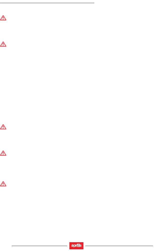
GENERAL INFORMATION
RSV 1000 R — RSV 1000 R FACTORY
COOLANT
DANGER
Coolant is toxic when ingested; it is an irritant, contact with eyes or skin may cause irritation.
In the event of contact with eyes, rinse repeatedly with abundant water and seek medical advice. In the event of ingestion, induce vomiting, rinse mouth and throat with abundant water and seek medical advice immediately.
DO NOT RELEASE INTO THE ENVIRONMENT. KEEP IT AWAY FROM CHILDREN.
DANGER
Take care not to spill coolant onto hot engine parts. It may ignite and produce invisible flames. Wear latex gloves when servicing.
Do not ride when coolant is below the minimum level.
Coolant mixture is a 50% solution of water and anti-freeze. This is the ideal solution for most operating temperatures and provides good corrosion protection.
This solution is also suited for the warm season, as it is less prone to evaporative loss and will reduce the need for topups.
In addition, less water evaporation means fewer minerals salts depositing in the radiator, which helps preserve the cooling system’s efficiency.
When temperature drops below zero degrees centigrade, check the cooling system frequently and add more anti-freeze (up to 60% maximum) to the solution.
Use distilled water in the coolant mixture. Tap water will damage the engine.
Refer to the chart given below and add water with the quantity of anti-freeze to obtain a solution with the desired freezing point:
|
Freezing point F°(C°) |
Coolant % of volume |
|
-4° (-20°) |
35 |
|
-22° (-30°) |
45 |
|
-40° (-40°) |
55 |
NOTE Coolants have different specifications. The protection degree is written on the label.
WARNING
Use nitrate-free coolant only, with a protection until at least -31°F (-35°C).
DRIVE CHAIN
Check the drive chain operation, slack and lubrication at regular intervals.
The vehicle is equipped with an endless chain with a joint link.
WARNING
If too slack, the chain can come off the front or rear sprockets thus leading to serious accidents and damage to the vehicle, with consequent serious personal injury or death.
Do not use the vehicle if the chain tension has not been correctly adjusted.
To check the chain, take it with your hand where it turns on the rear sprocket and pull it as to separate it from the crown itself.
If you can move the chain apart of the front sprocket for more than 0.125 in (3 mm), change chain, crown and pinion.
DANGER
If not properly maintained, the chain can undergo early wear out and lead to the damage of both crown and pinion.
Perform chain maintenance operations more frequently if the vehicle is used on rainy or dusty areas.
1 — 10

GENERAL INFORMATION
RSV 1000 R — RSV 1000 R FACTORY
TIRES
WARNING
If tires are excessively inflated, the vehicle will be hard and uneasy to ride, thus making you feel not at your ease.
In addition the roadworthiness, mainly on wet surfaces and during cornering, will be impaired. Flat tires (insufficient pressure) can slip on the rim and make you lose control of the vehicle. In this case too, both vehicle roadworthiness, handling and brake efficiency will be impaired.
Tires changing, repair, maintenance and balancing must be carried out by specialized technicians using suitable equipment.
When new, tires can have a thin slippery protective coating. Drive carefully for the first kilometers (miles). Never use rubber treating substances on tires.
In particular, avoid contact with fluid fuels, leading to a rapid wear. In case of contact with oil or fuel, do not clean but change tires.
DANGER
Some of the factory-assembled tires of this vehicle are provided with wear indicators. There are several kinds of wear indicators.
For more information on how to check the wear, contact your Dealer. Visually check if the tires are worn and in this case have them changed. If a tire deflates while driving, stop immediately.
Avoid hard brakings or moves and do not close throttles too abruptly.
Slowly close throttle grip, move to the edge of the road and use the engine brake to slow down until coming to a halt.
Failure to comply with these recommendations can lead to serious accidents and consequent personal injuries or death.
Do not install tires with air tube on rims for tubeless tires and vice versa.
1 — 11
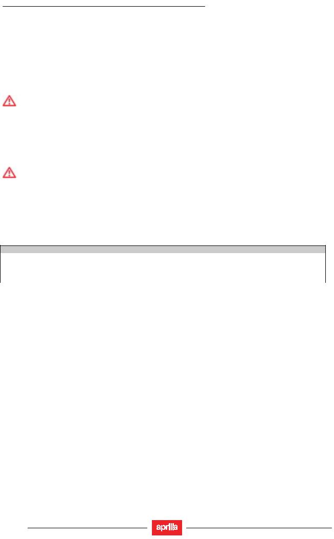
GENERAL INFORMATION
RSV 1000 R — RSV 1000 R FACTORY
1.4. RUNNING-IN
1.4.1.RUNNING-IN RECOMMENDATIONS
Running-in the engine is essential to ensure its duration and correct functioning.
If possible, drive on hilly roads and/or roads with many bends, so that the engine, the suspensions and the brakes undergo a more effective running-in.
During the running-in, change speed.
In this way the components are first «loaded» and then «relieved» and the engine’s parts can thus cool down. Even if it is important to stress the engine components during running-in, take care not to over do it.
WARNING
You can expect the best performance levels from the vehicle only after the first 932 mi (1500 km) of run- ning-in.
Keep to the following indications:
•Do not open the throttle completely if the speed is low, both during and after the running-in.
•During the first 62 mi (100 km) pull the brakes with caution, avoiding sharp and prolonged braking. This ensures a correct bedding-in of the pads on the brake disc.
•During the first 621 mi (1000 km) never exceed 6000 rpm (see table).
WARNING
After the first 621 mi (1000 km), Dealers carry out the checks indicated in the column «After runningin», see (REGULAR SERVICE INTERVALS CHART), in order to avoid hurting yourself or other people and/or damaging the vehicle.
•Between the first 621 mi (1000 km) and 932 mi (1500 km) drive more briskly, change speed and use the maximum acceleration only for a few seconds, in order to ensure better coupling of the components; never exceed 7500 rpm (see table).
•After the first 932 mi (1500 km) you can expect better performance from the engine, however, without exceeding the maximum allowed [11000 rpm].
Engine maximum rpm recommended
|
Mileage mi (Km) |
rpm |
|
0÷621 (1000 ) |
6000 |
|
621÷932 (1000÷1500 ) |
7500 |
|
Over 932 (1500) |
11000 |
1 — 12

RSV 1000 R — RSV 1000 R FACTORY
1.5. VEHICLE IDENTIFICATION
1.5.1.POSITION OF THE SERIAL NUMBERS
These numbers are necessary for the vehicle’s registration.
IMPORTANT Do not alter the identification numbers if you do not want to incur severe penal and administrative sanctions; in particular, altering the frame number voids the warranty.
FRAME NUMBER
The frame number (1) is stamped on the right hand side of the headstock.
ENGINE NUMBER
The engine number (2) is stamped on the rear part of the engine, near the pinion.
INFORMATION CONTAINED IN THE VEHICLE IDENTIFICATION NUMBER
Description of the vehicle identification number (V.I.N.), stamped on the steering head of the frame (1) and on the identification plate (3)
GENERAL INFORMATION
1 — 13
![]()
GENERAL INFORMATION
RSV 1000 R — RSV 1000 R FACTORY
DIGIT MEANING
1.Manufacturer’s identification alphanumeric code.
2.Vehicle type.
3.Model.
4.Country for which the vehicle is intended.
5.#= Check digit number.
6.Model year.
7.Assembling factory designation (N = NOALE-VE- ,
S = SCORZÉ -VE- ,
0 = NOT SPECIFIED).
8.Sequential serial number.
1 — 14
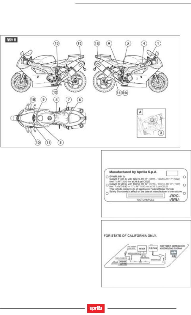
RSV 1000 R — RSV 1000 R FACTORY
1.6.POSITION OF THE WARNING ADHESIVE LABELS
1.6.1.POSITION OF THE WARNING ADHESIVE LABELS
1
2
GENERAL INFORMATION
1 — 15
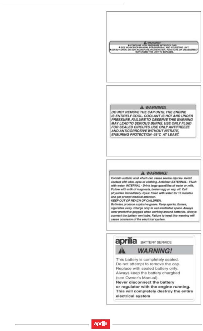
GENERAL INFORMATION
RSV 1000 R — RSV 1000 R FACTORY
3
4
5
6
1 — 16
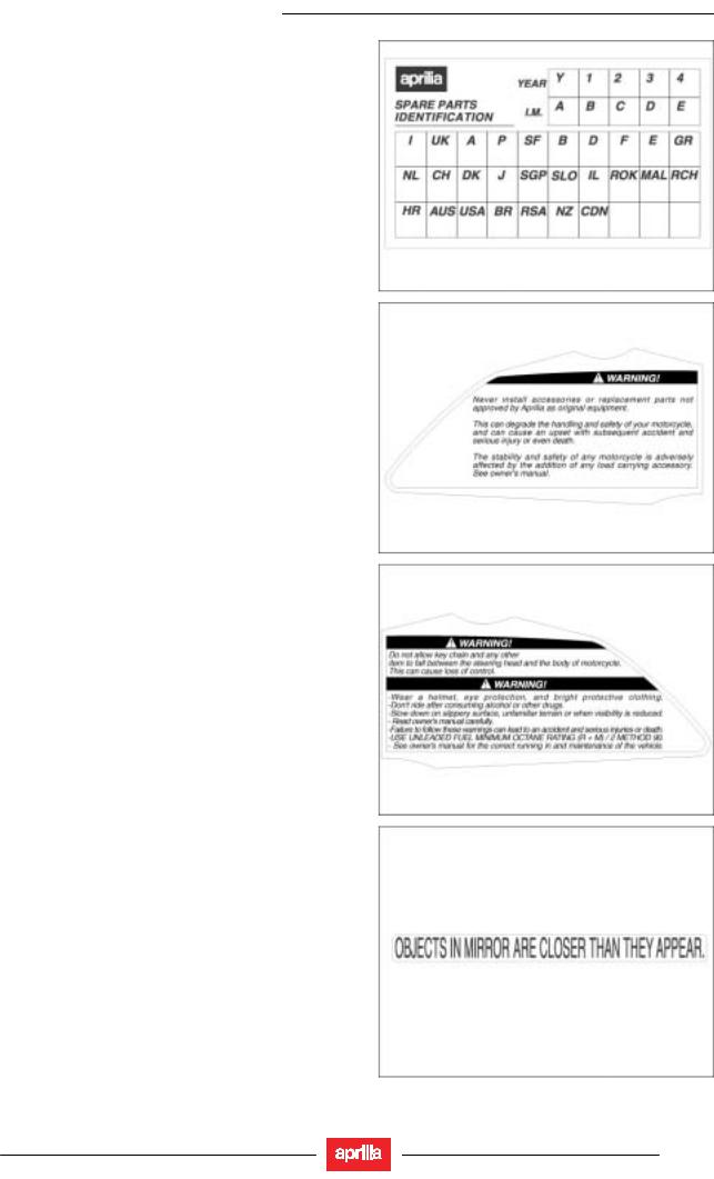
GENERAL INFORMATION
RSV 1000 R — RSV 1000 R FACTORY
7
8
9
10
1 — 17
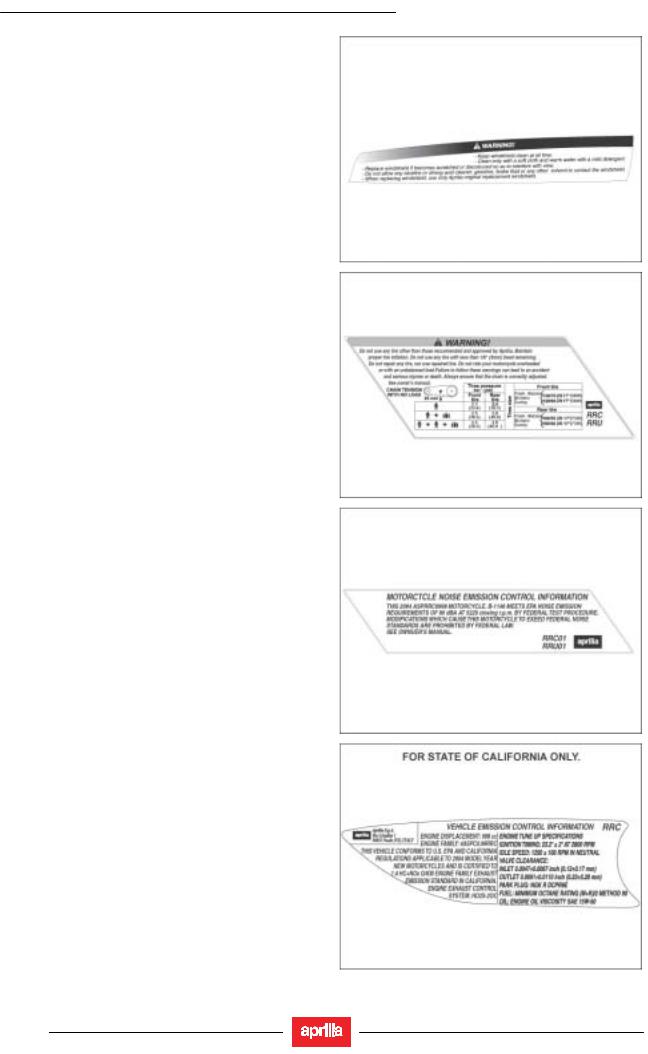
GENERAL INFORMATION
RSV 1000 R — RSV 1000 R FACTORY
11
12
13
14
1 — 18
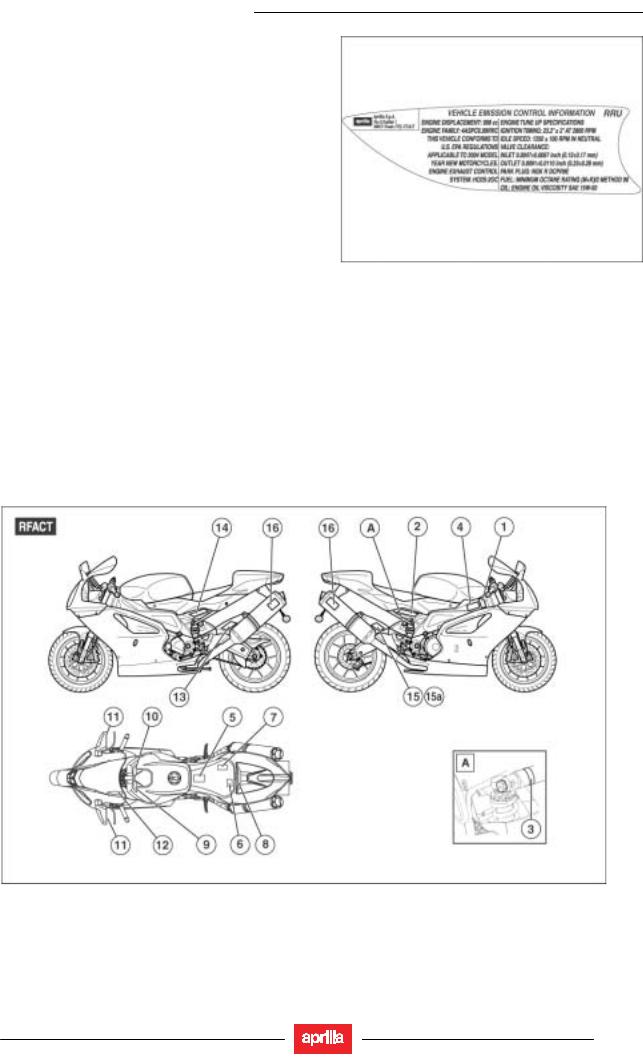
GENERAL INFORMATION
RSV 1000 R — RSV 1000 R FACTORY
14a
1 — 19
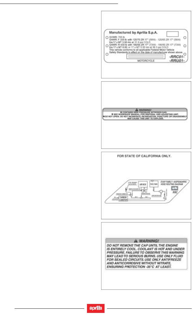
GENERAL INFORMATION
RSV 1000 R — RSV 1000 R FACTORY
1
2
3
4
1 — 20
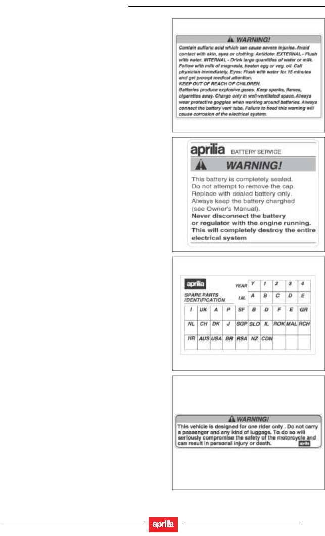
GENERAL INFORMATION
RSV 1000 R — RSV 1000 R FACTORY
5
6
7
8
1 — 21
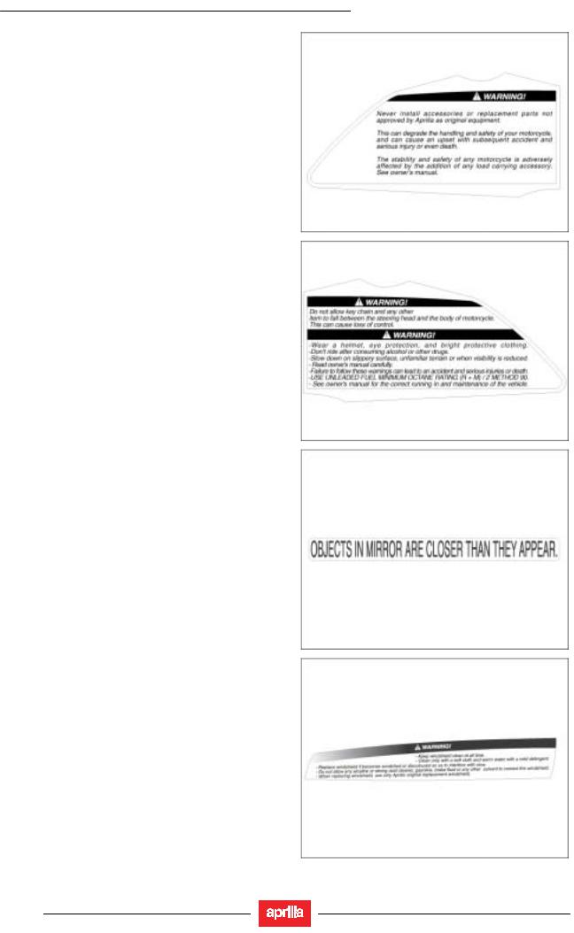
GENERAL INFORMATION
RSV 1000 R — RSV 1000 R FACTORY
9
10
11
12
1 — 22
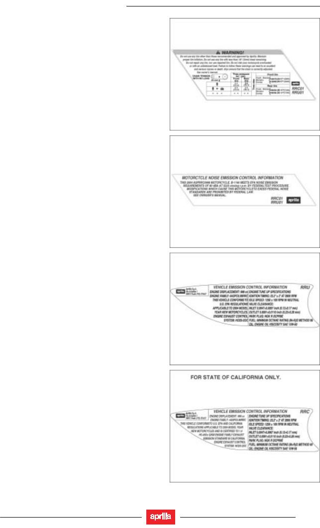
GENERAL INFORMATION
RSV 1000 R — RSV 1000 R FACTORY
13
14
15
15a
1 — 23
![]()
GENERAL INFORMATION
RSV 1000 R — RSV 1000 R FACTORY
1 — 24

GENERAL INFORMATION
RSV 1000 R — RSV 1000 R FACTORY
1.6.2.CALIFORNIA EVAPORATIVE EMISSION SYSTEM
FOR STATE OF CALIFORNIA ONLY.
1.The system consists of:
2.Fuel tank
3.Fuel tank breather line
4.Breather line (to 2 way ventilation valve)
5.2 way ventilation valve
6.Breather line (to carbon canister)
7.Carbon canister
8.Drain line (to norrow passage)
9.Restrictor Ø 0.06 in (Ø 1.5 mm)
10.Drain line (to tee)
11.Tee
12.Drain line (to manifold vacum port)
13.Manifold vacum port (right front part of throttle body)
14.Warm air inlet (from armosphere to canister)
1 — 25

GENERAL TECHNICAL INFORMATION
RSV 1000 R — RSV 1000 R FACTORY
|
GENERAL TECHNICAL INFORMATION |
2 |
2 — 1

|
GENERAL TECHNICAL INFORMATION |
||
|
RSV 1000 R — RSV 1000 R FACTORY |
||
|
SUMMARY |
||
|
2.1. |
GENERAL TECHNICAL INFORMATION ………………………………………………………………………………………….. |
3 |
|
2.1.1. |
TECHNICAL DATA ……………………………………………………………………………………………………………….. |
3 |
|
2.1.2. |
PERIODIC MAINTENANCE CHART………………………………………………………………………………………… |
7 |
|
2.1.3. |
TABLE OF LUBRICANTS ………………………………………………………………………………………………………. |
9 |
|
2.1.4. |
TIGHTENING TORQUES …………………………………………………………………………………………………….. |
10 |
|
2.1.5. |
SPECIAL TOOLS………………………………………………………………………………………………………………… |
14 |
|
2.1.6. |
ARRANGEMENT OF THE MAIN ELEMENTS …………………………………………………………………………. |
21 |
|
2.1.7. |
ARRANGEMENT OF THE INSTRUMENTS/CONTROLS………………………………………………………….. |
25 |
|
2.1.8. |
DASHBOARD OPERATION …………………………………………………………………………………………………. |
26 |
|
2.1.9. |
SYSTEMS DIAGRAM ………………………………………………………………………………………………………….. |
34 |
2 — 2

GENERAL TECHNICAL INFORMATION
RSV 1000 R — RSV 1000 R FACTORY
2.1. GENERAL TECHNICAL INFORMATION
2.1.1.TECHNICAL DATA
|
DIMENSIONS |
|||||
|
Max. length |
79.724 in (2025 mm) |
||||
|
Max. length |
28.740 in (730 mm) |
||||
|
Max. height (incl. windshield) |
44.685 in (1135 mm) |
||||
|
Rider’s seat height |
32.283 in (820 mm) |
||||
|
Wheelbase |
55.512 in (1410 mm) |
||||
|
Minimum ground clearance |
5.118 in (130 mm) |
||||
|
Weight in running order |
RSV R 473.993 lb (215 kg) –RFACT 460.766 lb (209 kg) |
||||
|
ENGINE |
|||||
|
Model |
V990 NG |
||||
|
Type |
4-stroke V 60* twin-cylinder, with 4 valves per cylinder, DOHC. |
||||
|
No. of cylinders |
2 |
||||
|
Total displacement |
60.902 in3 (998 cm3) |
||||
|
Bore/stroke |
3.819 in/2.657 in (97 mm/67,5 mm) |
||||
|
Compression ratio |
11,8 ± 0,4: 1 |
||||
|
Starting |
Electric starter |
||||
|
Engine idling speed |
1280 ± 100 rpm |
||||
|
Clutch |
Multiplate wet clutch, hydraulically operated, control on left side of han- |
||||
|
dlebar and PPC device |
|||||
|
Lubricating system |
Dry sump with separate oil tank and oil cooler |
||||
|
Air cleaner |
Dry filter cartridge |
||||
|
Cooling system |
Liquid coolant |
||||
|
GEARBOX |
|||||
|
Type |
Mechanical, 6 gears with foot control on engine’s left side |
||||
|
CAPACITIES |
|||||
|
Fuel (including reserve) |
4.755 gal (18 l) |
||||
|
Fuel reserve |
1.189 ± 0.264 gal (4,5 ± 1 l) |
||||
|
Engine oil |
Oil change 225.788 in3 (3700 cm3) — oil and oil filter change 237.993 in3 |
||||
|
(3900 cm3) |
|||||
|
Front fork oil RSV R |
31.732 ± 0.152 in3 (520 ± 2,5 cm3) (each leg) |
||||
|
Front fork “R FACTORY” RFACT (RSV R |
30.512 ± 0.152 in3 (500 ± 2,5 cm3) (each leg) |
||||
|
OPT) oil |
|||||
|
Coolant |
0.581 gal (2,2 l) (50% water + 50% anti-freeze with ethylene glycol) |
||||
|
Seat |
2 (RFACT USA version: single-seater only) |
||||
|
Max. load |
RSV R 396.832 lb (180 kg) (rider + passenger + luggage) – RFACT |
||||
|
USA 231.485 lb (105 kg) |
|||||
|
TRANSMISSION RATIOS |
|||||
|
Ratio |
Primary |
Secondary |
Final drive |
Total ratio |
|
|
1st |
31/60 = 1: 1,935 |
15/34 = 1: 2,267 |
16/40 = 1: 2,500 |
1:10,968 |
|
|
2nd |
19/31 = 1: 1,632 |
1:7,895 |
|||
|
3rd |
20/26 = 1: 1,300 |
1:6,290 |
|||
|
4th |
22/24 = 1: 1,091 |
1:5,279 |
|||
|
5th |
25/24 = 1: 0,960 |
1:4,645 |
|||
|
6th |
26/23 = 1: 0,885 |
1:4,280 |
|||
|
DRIVE CHAIN |
|||||
|
Type |
Endless (with no master link) with O-ring links |
||||
|
Endless |
525 |
||||
|
FUEL SYSTEM |
|||||
|
Type |
Electronic injection (Multipoint) |
||||
|
Choke |
Ø 2.244 in (Ø 57 mm) |
||||
|
FUEL |
|||||
|
Fuel |
Premium-grade unleaded gas, minimum octane rating 95 (ROM) and 85 |
||||
|
(MON). |
2 — 3

|
GENERAL TECHNICAL INFORMATION |
||||
|
RSV 1000 R — RSV 1000 R FACTORY |
||||
|
FRAME |
||||
|
Type |
Two-beam frame with light alloy cast elements and extruded elements |
|||
|
Steering head angle |
25° |
|||
|
Trail |
3.937 in (100 mm) (with 120/70 front tire) |
|||
|
SUSPENSION |
||||
|
Front |
Adjustable hydraulic upside-down fork, Ø 1.693 in (Ø 43 mm) |
|||
|
Travel |
RSV R 4.999 in (127 mm) – RFACT (RSV R OPT) 4.724 in (120 mm) |
|||
|
Rear |
Light-alloy swinging arm with differentiated profiles on both sides and adjustable air/oil- |
|||
|
sprung mono-shock absorber |
||||
|
Wheel travel |
5.31 in (135 mm) |
|||
|
BRAKES |
||||
|
Front |
Twin floating disk — Ø 12.598 in (Ø 320 mm), four-piston calipers — Ø 1.338 in (Ø 34 mm) |
|||
|
Rear |
Disk brake — Ø 8.661 in (Ø 220 mm), twin-piston caliper — Ø 1.260 in (Ø 32 mm) |
|||
|
WHEEL RIMS |
||||
|
Type |
Light alloy, spindle can be removed |
|||
|
Front |
3,50 x 17″ |
|||
|
Rear |
6,00 x 17″ |
2 — 4

|
GENERAL TECHNICAL INFORMATION |
||||||||||||||||||||||||||||||||
|
RSV 1000 R — RSV 1000 R FACTORY |
||||||||||||||||||||||||||||||||
|
TIRES |
||||||||||||||||||||||||||||||||
|
Recom- |
Pressure kPa (bar) |
|||||||||||||||||||||||||||||||
|
Wheel |
Make |
Model |
Type |
Size |
Alternative |
# |
$ |
|||||||||||||||||||||||||
|
mended |
Rider |
Rider and |
Rider |
|||||||||||||||||||||||||||||
|
passenger |
||||||||||||||||||||||||||||||||
|
** Front |
PIRELLI |
DIABLO |
CORSA |
120/70– |
# |
$ |
RSV R + R |
230 (2,3) |
250 (2,5) |
210 |
||||||||||||||||||||||
|
ZR 17″ |
FACT |
(2,1) |
||||||||||||||||||||||||||||||
|
** Rear |
PIRELLI |
DIABLO |
CORSA |
190/50– |
# |
$ |
RSV R + R |
250 (2,5) |
280 (2,8) |
200 |
||||||||||||||||||||||
|
ZR 17″ |
FACT |
(2,0) |
||||||||||||||||||||||||||||||
|
* Front |
PIRELLI |
DRAGON |
– |
120/70– |
# |
$ |
RSV R + R |
230 (2,3) |
250 (2,5) |
210 |
||||||||||||||||||||||
|
SUPER- |
ZR 17″ |
FACT |
(2,1) |
|||||||||||||||||||||||||||||
|
CORSA |
||||||||||||||||||||||||||||||||
|
* Rear |
PIRELLI |
DRAGON |
– |
180/55– |
# |
$ |
RSV R + R |
250 (2,5) |
280 (2,8) |
200 |
||||||||||||||||||||||
|
SUPER- |
ZR 17″ |
FACT |
(2,0) |
|||||||||||||||||||||||||||||
|
CORSA |
||||||||||||||||||||||||||||||||
|
** Front |
METZELER |
SPORT- |
M1 |
120/70– |
# |
$ |
RSV R + R |
230 (2,3) |
250 (2,5) |
210 |
||||||||||||||||||||||
|
TEC |
ZR 17″ |
FACT |
(2,1) |
|||||||||||||||||||||||||||||
|
Rear |
METZELER |
SPORT- |
M1 |
180/55– |
# |
$ |
RSV R + R |
250 (2,5) |
280 (2,8) |
200 |
||||||||||||||||||||||
|
TEC |
ZR 17″ |
FACT |
(2,0) |
|||||||||||||||||||||||||||||
|
** Rear |
METZELER |
SPORT- |
M1 |
190/50– |
# |
$ |
RSV R + R |
250 (2,5) |
280 (2,8) |
200 |
||||||||||||||||||||||
|
TEC |
ZR 17″ |
FACT |
(2,0) |
|||||||||||||||||||||||||||||
|
Front |
METZELER |
RENNSPO |
– |
120/70– |
— |
$ |
RSV R + R |
— |
— |
210 |
||||||||||||||||||||||
|
RT |
ZR 17″ |
FACT |
(2,1) |
|||||||||||||||||||||||||||||
|
Rear |
METZELER |
RENNSPO |
– |
180/55– |
— |
$ |
RSV R + R |
— |
— |
200 |
||||||||||||||||||||||
|
RT |
ZR 17″ |
FACT |
(2,0) |
|||||||||||||||||||||||||||||
|
** Front |
MICHELIN |
PILOT |
E |
120/70– |
# |
— |
RSV R |
230 (2,3) |
250 (2,5) |
— |
||||||||||||||||||||||
|
SPORT |
ZR 17″ |
|||||||||||||||||||||||||||||||
|
TL |
||||||||||||||||||||||||||||||||
|
** Rear |
MICHELIN |
PILOT |
E |
190/50– |
# |
— |
RSV R |
250 (2,5) |
280 (2,8) |
— |
||||||||||||||||||||||
|
SPORT |
ZR 17″ |
|||||||||||||||||||||||||||||||
|
TL |
||||||||||||||||||||||||||||||||
|
Front |
MICHELIN |
PILOT |
— |
120/70– |
– |
$ |
RFACT |
– |
– |
210 |
||||||||||||||||||||||
|
SPORT |
ZR 17″ |
(2,1) |
||||||||||||||||||||||||||||||
|
CUP |
||||||||||||||||||||||||||||||||
|
Front |
MICHELIN |
PILOT |
— |
180/55– |
– |
$ |
RFACT |
– |
– |
190 |
||||||||||||||||||||||
|
SPORT |
ZR 17″ |
(1,9) |
||||||||||||||||||||||||||||||
|
CUP |
||||||||||||||||||||||||||||||||
|
Front |
MICHELIN |
PILOT |
H 2 |
120/70– |
– |
$ |
RFACT |
– |
– |
210 |
||||||||||||||||||||||
|
RACE |
ZR 17″ |
(2,1) |
||||||||||||||||||||||||||||||
|
Rear |
MICHELIN |
PILOT |
H 2 |
180/55– |
– |
$ |
RFACT |
– |
– |
190 |
||||||||||||||||||||||
|
RACE |
ZR 17″ |
(1,9) |
||||||||||||||||||||||||||||||
|
** Front |
DUNLOP |
SPORT- |
D 208 |
120/70– |
# |
— |
RSV R+ |
230 (2,3) |
250 (2,5) |
— |
||||||||||||||||||||||
|
MAX |
ZR 17″ |
RFACT |
||||||||||||||||||||||||||||||
|
** Rear |
DUNLOP |
SPORT- |
D 208 |
190/50– |
# |
– |
RSV R+ |
250 (2,5) |
280 (2,8) |
– |
||||||||||||||||||||||
|
MAX |
ZR 17″ |
RFACT |
||||||||||||||||||||||||||||||
|
Front |
DUNLOP |
SPORT- |
D 208 |
120/55– |
— |
$ |
RFACT |
— |
— |
210 |
||||||||||||||||||||||
|
MAX |
RR |
ZR 17″ |
(2,1) |
|||||||||||||||||||||||||||||
|
Rear |
DUNLOP |
SPORT- |
D 208 |
180/55– |
— |
$ |
RFACT |
— |
— |
190 |
||||||||||||||||||||||
|
MAX |
RR |
ZR 17″ |
(1,9) |
|||||||||||||||||||||||||||||
|
* = standard |
RFACT |
**= standard |
RSV R |
# = Standard use |
$= Racing use |
2 — 5

|
GENERAL TECHNICAL INFORMATION |
||||
|
RSV 1000 R — RSV 1000 R FACTORY |
||||
|
SPARK PLUGS |
||||
|
Standard |
NGK R DCPR9E |
|||
|
Electrode gap |
0.024– 0.028 in (0,6 – 0,7 mm) |
|||
|
Resistance |
5 kΩ |
|||
|
ELECTRIC SYSTEM |
||||
|
Battery |
12 |
V – 10 Ah |
||
|
Main fuses |
30 |
A |
||
|
Auxiliary fuses |
5 A, 15 A, 20 A |
|||
|
Generator (permanent-wound type) |
12 |
V – 500 W |
||
|
BULBS |
||||
|
Low beam (halogen) |
12 V – 55 W H7U x 2 |
|||
|
High beam (halogen) |
12 V – 55 W H7U x 2 |
|||
|
Front parking light |
12 |
V – 5 W |
||
|
Direction indicators |
12 |
V – 10 W |
||
|
Number plate light |
12 |
V – 5 W |
||
|
Stop/rear parking lights |
LED |
|||
|
Rev counter light |
LED |
|||
|
Left multifunction display |
LED |
|||
|
WARNING LIGHTS |
||||
|
Neutral |
LED |
|||
|
Direction indicators |
LED |
|||
|
Fuel reserve |
LED |
|||
|
High beam |
LED |
|||
|
Stand down |
LED |
|||
|
General warning |
LED |
|||
|
Red line |
LED |
|||
|
Immobilizer |
LED |
2 — 6

GENERAL TECHNICAL INFORMATION
RSV 1000 R — RSV 1000 R FACTORY
2.1.2.PERIODIC MAINTENANCE CHART
OPERATIONS TO BE CARRIED OUT BY THE Aprilia Official Dealer (CAN BE CARRIED OUT BY THE USER AS WELL).
|
Key |
|
|
1 = |
check and clean, adjust, lubricate or replace, if necessary; |
|
2 = |
clean; |
|
3 = |
replace |
|
4 = |
adjust. |
(*) = Check every two weeks or at the specified intervals.
NOTE Halve the maintenance intervals if the vehicle is used in rainy or dusty conditions, on rough roads or for racing.
|
Component |
Post running-in |
Every 3125 mi (5000 |
Every 6250 mi |
Every 12500 mi |
||||||||
|
[625 mi (1000 |
Km) (only for inten- |
(10000 Km) or 12 |
(20000 Km) or 24 |
|||||||||
|
Km)] |
sive racing use) |
months |
months |
|||||||||
|
Spark plug |
3 |
1 |
3 |
|||||||||
|
Air cleaner |
3 |
1 |
3 |
|||||||||
|
Engine oil filter |
3 |
3 |
3 |
|||||||||
|
Engine oil filter (on oil tank) |
2 |
2 |
2 |
|||||||||
|
Light operation/beam setting |
1 |
|||||||||||
|
Light system |
1 |
1 |
||||||||||
|
Safety switches |
1 |
1 |
||||||||||
|
Clutch fluid |
1 |
1 |
1 |
|||||||||
|
Brake fluid |
1 |
1 |
1 |
|||||||||
|
Coolant |
1 |
1 |
1 |
|||||||||
|
Engine oil |
3 |
3 |
3 |
|||||||||
|
Tires |
1 |
1 |
||||||||||
|
Tire pressure (*) |
4 |
4 |
||||||||||
|
Error warning light (on |
each start-up: 1 |
|||||||||||
|
dashboard) |
||||||||||||
|
Drive chain slack and |
every 625 mi (1000 Km): 1 |
|||||||||||
|
lubrication |
||||||||||||
|
Brake pad wear |
1 |
every 625 mi (1000 |
before each ride and every 1250 mi |
|||||||||
|
Km): 1 |
(2000 Km): 1 |
|||||||||||
2 — 7

GENERAL TECHNICAL INFORMATION
RSV 1000 R — RSV 1000 R FACTORY
OPERATIONS TO BE CARRIED OUT BY THE Aprilia Official Dealer.
|
Key |
|
|
1 = |
check and clean, adjust, lubricate or replace, if necessary; |
|
2 = |
clean; |
|
3 = |
replace |
|
4 = |
adjust. |
(*) = only for versions with magnesium wheels: check that rim paint is in good conditions.
NOTE Halve the maintenance intervals if the vehicle is used in rainy or dusty conditions, on rough roads or for racing.
|
Post running-in |
Every 3125 mi (5000 |
Every 6250 mi |
Every 12500 mi |
|||||||||||
|
Component |
Km) (only for inten- |
(10000 Km) or 12 |
(20000 Km) or 24 |
|||||||||||
|
[625 mi (1000 Km)] |
||||||||||||||
|
sive racing use) |
months |
months |
||||||||||||
|
Rear shock absorber |
1 |
1 |
||||||||||||
|
Gearbox |
every 625 mi (1000 |
|||||||||||||
|
Km): 1 |
||||||||||||||
|
Bowden cables and con- |
1 |
1 |
1 |
|||||||||||
|
trols |
||||||||||||||
|
Rear suspension linkage |
1 |
|||||||||||||
|
bearings |
||||||||||||||
|
Steering bearings |
and |
1 |
1 |
1 |
||||||||||
|
steering play |
||||||||||||||
|
Wheel bearings |
1 |
1 |
||||||||||||
|
Brake discs |
1 |
1 |
1 |
|||||||||||
|
Vehicle operation |
1 |
1 |
1 |
|||||||||||
|
Valve clearance |
4 |
4 |
||||||||||||
|
Braking systems |
1 |
1 |
1 |
|||||||||||
|
Cooling system |
1 |
1 |
||||||||||||
|
Clutch fluid |
every 12 months: 3 |
every 24 |
months: 3 |
|||||||||||
|
Brake fluid |
every 12 months: 3 |
every 24 months: 3 |
||||||||||||
|
Coolant |
every 24 months: 3 |
|||||||||||||
|
Fork oil (RSV R) |
After the first 6250 mi (10000 Km) and every |
|||||||||||||
|
12500 mi (20000 Km): afterwards: 3 |
||||||||||||||
|
Fork oil (RFACT) |
3 |
3 |
||||||||||||
|
Fork oil seals (RSV R) |
After the first 18650 |
mi (30000 Km) and |
||||||||||||
|
every 12500 mi (20000 Km):afterwards: 3 |
||||||||||||||
|
Fork oil seals (RFACT) |
1 |
1 |
||||||||||||
|
Brake pads |
if worn: 3 |
|||||||||||||
|
Wheels/Tires (*) |
1 |
1 |
1 |
|||||||||||
|
Nut, bolt, screw tightening |
1 |
1 |
1 |
|||||||||||
|
Cylinder synchronization |
1 |
1 |
||||||||||||
|
Suspension and trim |
1 |
1 |
1 |
|||||||||||
|
Final drive (chain, |
rear |
1 |
1 |
|||||||||||
|
and front sprocket) |
||||||||||||||
|
Fuel pipes |
1 |
every 4 years: 3 |
||||||||||||
|
Clutch wear |
1 |
|||||||||||||
|
Pistons |
1 |
2 — 8
![]()
GENERAL TECHNICAL INFORMATION
RSV 1000 R — RSV 1000 R FACTORY
|
2.1.3. |
TABLE OF LUBRICANTS |
|||||||||||
|
LUBRICANT |
PRODUCT |
|||||||||||
|
RECOMMENDED: |
EXTRA RAID 4, SAE 15W — 50 or |
TEC 4T, |
||||||||||
|
Engine oil |
SAE 15W — 50. |
|||||||||||
|
As an alternative to recommended oils, top brand oils meeting or exceeding |
||||||||||||
|
CCMC G-4, A.P.I. S.G. specifications can be used. |
||||||||||||
|
RECOMMENDED: |
F.A. 5W, |
F.A. 20W; as an alternative, |
||||||||||
|
FORK 5W or |
FORK 20W. |
|||||||||||
|
When you wish to obtain an intermediate response between those offered |
||||||||||||
|
by |
F.A. 5W and |
F.A. 20W oils or |
FORK 5W and |
|||||||||
|
RSV R fork oil |
FORK 20W oils, you may mix the different products as follows: |
|||||||||||
|
SAE 10W = |
F.A. 5W 67% of volume + |
F.A. 20W 33% of volume, or |
||||||||||
|
FORK 5W 67% of volume + |
FORK 20W 33% |
|||||||||||
|
of volume. |
||||||||||||
|
SAE 15W = |
F.A. 5W 33% of volume + |
F.A. 20W 67% of volume, or |
||||||||||
|
FORK 5W 33% of volume + |
FORK 20W 67% |
|||||||||||
|
of volume. |
||||||||||||
|
RFACT (RSV R OPT) Fork oil type “R |
ÖHLINS 5W |
|||||||||||
|
FACTORY” |
||||||||||||
|
RECOMMENDED: |
BIMOL GREASE 481 — |
AUTOGREASE MP or |
||||||||||
|
GREASE 30. |
||||||||||||
|
Bearings and other lubrication points |
As an alternative to recommended grease, use top brand rolling bearing |
|||||||||||
|
grease that will resist a temperature range of -30°C — +140°C, with dropping |
||||||||||||
|
point 150°C — 230°C, high corrosion protection, good resistance to water |
||||||||||||
|
and oxidation. |
||||||||||||
|
Battery lead protection |
Use neutral grease or Vaseline. |
|||||||||||
|
Chains |
Spray grease RECOMMENDED: |
CHAIN SPRAY or |
CHAIN |
|||||||||
|
LUBE. |
||||||||||||
|
RECOMMENDED: The system is filled with |
Autofluid FR. DOT 4 (the |
|||||||||||
|
braking system is also compatible with DOT 5); |
BRAKE 5.1 DOT 4 |
|||||||||||
|
Brake fluid |
(the braking system is also compatible with DOT 5). |
|||||||||||
|
NOTE Use new brake fluid only. Do not mix different brands or types of oil |
||||||||||||
|
without having checked bases compatibility. |
||||||||||||
|
F.F., DOT 5 (Compatibile DOT 4) ; |
BRAKE 5.1 DOT 5 (the |
|||||||||||
|
Clutch fluid |
braking system is also compatible with DOT 4). |
|||||||||||
|
NOTE Use new clutch fluid only |
||||||||||||
|
RECOMMENDED: |
ECOBLU -40 °C — |
COOL. |
||||||||||
|
Engine coolant |
NOTE Use |
only nitrite-free anti-freeze and corrosion inhibitors with a |
||||||||||
|
freezing point of -35°C as a minimum. |
||||||||||||
2 — 9

GENERAL TECHNICAL INFORMATION
RSV 1000 R — RSV 1000 R FACTORY
|
2.1.4. |
TIGHTENING TORQUES |
||||
|
DESCRIPTION |
<![if ! IE]>
<![endif]>QUANTITY |
<![if ! IE]>
<![endif]>SCREW / NUT |
<![if ! IE]>
<![endif]>TORQUE (ftlb) |
<![if ! IE]>
<![endif]>NOTES |
|
|
ENGINE |
|||||
|
Engine mounting to frame |
|||||
|
Front fitting |
2+2 |
M10 |
36,878 |
— |
|
|
Left side upper and lower rear fitting |
2 |
M10 |
36,878 |
— |
|
|
Adjuster bushing right side upper and lower rear fitting |
2 |
M20x1,5 |
8,851 |
— |
|
|
Locknut right side upper and lower rear fitting |
2 |
M20x1,5 |
36,878 |
— |
|
|
Screw right side upper and lower rear fitting |
2 |
M10 |
36,878 |
— |
|
|
Components mounted to engine |
|||||
|
Engine oil intake flange |
2 |
M6 |
7,376 |
— |
|
|
Engine oil outlet flange |
2 |
M6 |
7,376 |
— |
|
|
Rear brake lever support |
1 |
M6 |
7,376 |
— |
|
|
Rear brake lever support |
1 |
M8 |
18,439 |
— |
|
|
Rear brake pump support |
2 |
M8 |
18,439 |
— |
|
|
Pinion |
1 |
M10 |
36,878 |
Loctite 243 |
|
|
Clutch control cylinder |
3 |
M6 |
7,376 |
— |
|
|
Pinion cover |
3 |
M6 |
7,376 |
— |
|
|
Fuel delivery hose to throttle body |
1 |
M12x1,5 |
16,226 |
— |
|
|
72/78 Kw reduction bushing |
1 |
M5 |
2,213±10% |
Loctite 243 |
|
|
SWINGING ARM |
|||||
|
Swinging arm spindle nut |
1 |
M30x1,5 |
44,254 |
— |
|
|
Swinging arm spindle adjuster bushing |
1 |
M30x1,5 |
8,851 |
— |
|
|
Swinging arm spindle nut |
1 |
M20x1,5 |
66,38 |
— |
|
|
Caliper support pin |
1 |
M12 |
36,878 |
Loctite 243 |
|
|
Chain tensioner screw and nut |
1+1 |
M8 |
man. |
— |
|
|
Rear brake hose bracket |
3 |
M5 |
2,95 |
— |
|
|
Chain guard cover |
2 |
M5 |
2,95 |
— |
|
|
Chain shoe |
2 |
M5 |
2,213 |
— |
|
|
Chain guide plate |
1 |
M5 |
2,213 |
— |
|
|
Rear stand bushing |
2 |
M6 |
7,376 |
— |
|
|
Chain guide plate (nut) |
1 |
M6 |
7,376 |
— |
|
|
SIDE STAND |
|||||
|
Stand plate to frame |
1 |
M10 |
29,502 |
— |
|
|
Side stand pin |
1 |
M10x1,25 |
7,376 |
— |
|
|
Switch screw |
1 |
M6 |
7,376 |
Loctite 243 |
|
|
Locknut |
1 |
M10x1,25 |
22,127 |
— |
2 — 10

|
GENERAL TECHNICAL INFORMATION |
||||||||
|
RSV 1000 R — RSV 1000 R FACTORY |
||||||||
|
FRONT SUSPENSION |
||||||||
|
Front fork |
||||||||
|
Fork leg on top yoke |
1+1 |
M8 |
18,439 |
— |
||||
|
Fork leg on bottom yoke |
2+2 |
M8 |
18,439 |
— |
||||
|
tighten first |
||||||||
|
Head stock nut (tighten first, then slacken) |
1 |
M35x1 |
29,502 |
and then |
||||
|
slacken |
||||||||
|
Head stock nut (tighten down 2nd time) |
1 |
M35x1 |
14,751 |
tighten 2nd |
||||
|
time |
||||||||
|
Head stock locknut |
1 |
M35x1 |
man. + 90 |
— |
||||
|
grade |
||||||||
|
Top yoke cap |
1 |
M29x1 |
73,756 |
— |
||||
|
SHOWA fork hub clamps |
2+2 |
M8 |
18,226 |
— |
||||
|
OHLINS fork hub clamps |
2+2 |
M6 |
8,851 |
— |
||||
|
Steering damper |
||||||||
|
Steering damper collar to frame |
1 |
M6 |
7,376 |
Loctite 243 |
||||
|
Steering damper rod on bottom yoke |
1 |
M6 |
7,376 |
— |
||||
|
REAR SUSPENSION |
||||||||
|
Shock absorber |
||||||||
|
Shock absorber to frame |
1 |
M10 |
36,878 |
— |
||||
|
Linkages |
||||||||
|
Single conrod to frame |
1 |
M10 |
36,878 |
— |
||||
|
Single / double conrod |
1 |
M10 |
36,878 |
— |
||||
|
Double conrod swinging arm |
1 |
M10 |
36,878 |
— |
||||
|
Double conrod / shock absorber |
1 |
M10 |
36,878 |
— |
||||
|
ELECTRICAL SYSTEM |
||||||||
|
Battery cover bracket |
2 |
M5 |
1,475 |
— |
||||
|
Horn mount / bracket |
1 |
M8 |
18,439 |
— |
||||
|
Odometer sensor on rear brake caliper support |
1 |
M6 |
8,851 |
— |
||||
|
Rear direction indicators |
2 |
M4 |
0,738 |
— |
||||
|
Front direction indicators / rear view mirrors |
2+2 |
M6 |
3,688 |
— |
||||
|
Voltage regulator |
2 |
M6 |
3,688 |
— |
||||
|
Coil to bracket support |
1 |
M6 |
7,376 |
— |
||||
|
Tail light to rear fairing end |
4 |
M5 |
0,738 |
— |
||||
|
Head lamp to front fairing |
6 |
SWP5x14 |
1,475 |
— |
||||
|
Relay box to seat subframe |
2 |
M6 |
2,213 |
— |
||||
|
Relay cable to starter motor |
1 |
M6 |
3,688 |
— |
||||
|
Relay cable |
2 |
M6 |
1,475 |
— |
||||
|
FRONT WHEEL |
||||||||
|
Wheel axle nut |
1 |
M25x1,5 |
59,005 |
— |
||||
|
REAR WHEEL |
||||||||
|
Sprocket / Sprocket carrier |
5 |
M10 |
36,878 |
— |
||||
|
Wheel axle nut |
1 |
M25x1,5 |
88,507 |
— |
2 — 11

|
GENERAL TECHNICAL INFORMATION |
|||||||
|
RSV 1000 R — RSV 1000 R FACTORY |
|||||||
|
COOLING SYSTEM |
|||||||
|
Fan support |
2+2 |
M6 |
4,425 |
— |
|||
|
Expansion reservoir to frame |
2 |
M6 |
3,688 |
— |
|||
|
Expansion reservoir cap |
1 |
M28x3 |
man. |
— |
|||
|
Hose clips (8104097) |
— |
— |
2,213 |
— |
|||
|
BRAKE SYSTEM |
|||||||
|
Front brakes |
|||||||
|
Right and left brake calipers |
2+2 |
M10x1,25 |
36,878 |
— |
|||
|
Brake fluid reservoir to bracket |
1 |
M6 |
5,163 |
— |
|||
|
Brake fluid reservoir to bracket support |
1 |
M5 |
7,376 |
— |
|||
|
Brake disc |
1 |
M8 |
22,127 |
— |
|||
|
Front brake three-way fitting bracket |
6+6 |
M5 |
2,213 |
Loctite 243 |
|||
|
Rear brakes |
|||||||
|
Brake caliper |
2 |
M8 |
18,439 |
— |
|||
|
Brake lever pin |
1 |
M8 |
11,036 |
Loctite 243 |
|||
|
Brake fluid reservoir |
1 |
M5 |
0,738 |
— |
|||
|
Brake shaft locknut |
1 |
M6 |
man. |
— |
|||
|
Brake disc |
5 |
M8 |
22,127 |
Loctite 243 |
|||
|
Front brake hose three-way bracket |
1 |
M5 |
2,213 |
— |
|||
|
EXHAUST SYSTEM |
|||||||
|
Front exhaust hose to engine |
4 |
M6 |
8,851 |
— |
|||
|
Rear exhaust hose to engine (upper screws) |
2 |
M6 |
— |
Fasten by |
|||
|
hand |
|||||||
|
Rear exhaust hose to engine (lower screws) |
2 |
M6 |
8,851 |
— |
|||
|
Lambda sensor |
1 |
M18x1,5 |
28,027 |
— |
|||
|
FUEL TANK |
|||||||
|
Fuel pump flange |
|||||||
|
Fuel return fitting |
1 |
M6 |
4,425 |
Loctite 243 |
|||
|
Pump support to flange |
3 |
M5 |
1,475 |
— |
|||
|
Electrical terminals on flange |
2 |
M5 |
3,688 |
— |
|||
|
Fuel return cap |
1 |
M6 |
7,376 |
Loctite 243 |
|||
|
Fuel delivery hose on flange |
1 |
M12x1,5 |
18,226 |
— |
|||
|
Fuel level sensor on pump support |
2 |
SWP2,9×12 |
0,738 |
— |
|||
|
Fuel pump cabling on flange |
2 |
M6 |
7,376 |
— |
|||
|
Fuel tank |
|||||||
|
Filler cap to tank |
4 |
M5 |
3,688 |
— |
|||
|
Fuel pump flange to tank |
8 |
M5 |
4,425 |
— |
2 — 12

|
GENERAL TECHNICAL INFORMATION |
||||||
|
RSV 1000 R — RSV 1000 R FACTORY |
||||||
|
ENGINE OIL RESERVOIR |
||||||
|
Oil reservoir ( nuts ) |
3 |
M6 |
7,376 |
— |
||
|
Oil filter shank |
1 |
M20x1,5 |
22,127 |
— |
||
|
Oil drain cap |
1 |
M8 |
11,063 |
— |
||
|
Oil level bracket |
2 |
M10x1 |
14,751 |
— |
||
|
FRAME / FAIRING PANELS |
||||||
|
Front fairing to air scoop |
1 |
M6 |
2,213 |
— |
||
|
Windshield to front fairing |
8 |
M4 |
0,738 |
— |
||
|
Fairings to rider’s footrest and spacer |
2+2 |
M6 |
1,475 |
— |
||
|
Side fairing panels internal fitting w/ air dam |
4 |
M5 |
2,213 |
— |
||
|
Air dam to cooler’s support(s) |
2 |
M5 |
2,213 |
— |
||
|
Front fairing panel to bottom yoke |
3 |
M6 |
5,163 |
— |
||
|
License plate holder to lower seat subframe cover |
4 |
M6 |
2,213 |
— |
||
|
Lower panel to seat subframe |
3 |
M6 |
3,688 |
— |
||
|
Front lower seat subframe panel to frame |
2 |
M5 |
1,475 |
— |
||
|
Side body panels to tank |
1+1 |
M5 |
3,688 |
— |
||
|
Side body panels to seat subframe |
2+2 |
M5 |
2,213 |
— |
||
|
Rear mudguard |
4 |
M5 |
2,213 |
— |
||
|
Front mudguard |
4 |
M5 |
1,475 |
— |
||
|
Rectangular reflector to license plate holder |
2 |
M4 |
0,738 |
— |
||
|
Stand bushing — lower panel to seat subframe |
2 |
M6 |
8,851 |
— |
||
|
Left/right side fairing |
4 |
M5 |
2,213 |
— |
||
|
Rear fairing — passenger’s belt to seat subframe |
2 |
M6 |
8,851 |
— |
||
|
HANDLEBAR / CONTROLS |
||||||
|
Vibration damping weights |
2 |
M6 |
7,376 |
— |
||
|
Vibration damping weights terminals |
2 |
M18x1 |
25,815 |
— |
||
|
Handlebars to fork legs |
2 |
M8 |
36,878 |
— |
||
|
Handlebar safety screws |
2 |
M6 |
7,376 |
— |
||
|
Left dimmer switch |
1 |
M5x1 |
0,738 |
— |
||
|
Right dimmer switch |
1 |
M4 |
0,738 |
— |
||
|
Front brake pump |
2 |
M6 |
5,9 |
— |
||
|
Clutch pump |
2 |
M6 |
5,9 |
— |
||
|
Clutch reservoir on support |
1 |
M5 |
2,213 |
— |
||
|
Rear fairing lock |
2 |
M6 |
7,376 |
— |
||
|
Seat subframe |
4 |
M10 |
36,878 |
— |
||
|
AIRBOX |
||||||
|
Airbox cover |
7 |
SWP5x20 |
1,475 |
— |
||
|
Airbox to throttle body |
6 |
M6 |
5,163 |
— |
||
|
Intake funnels |
4 |
SWP3,9 |
0,738 |
— |
||
|
MAP sensor support |
1 |
SWP5x20 |
1,475 |
— |
||
|
Filter surround |
2 |
SWP5x20 |
1,475 |
— |
||
|
Air scoop to frame |
4 |
M6 |
7,376 |
— |
||
|
Rear view mirrors to air scoop |
3+3 |
M5 |
3,688 |
— |
2 — 13

GENERAL TECHNICAL INFORMATION
RSV 1000 R — RSV 1000 R FACTORY
2.1.5.SPECIAL TOOLS
In order to perform assembly, reassembly and settings correctly, special tools suitable for the task must be used. Using special tools prevents the potential risk of damage as a result of inappropriate tools and/or improvised methods.
Below is a list of the special tools designed especially for this specific vehicle. If necessary, request the multi-purpose special tools.
CAUTION
Before using the special tools, consult any documents attached.
SUPPORT STANDS
|
Pos. |
Aprilia part# (tool description and function) |
A 8140176 (complete support stand kit)
1 8146486 (front support stand)
2 xxxxxxx N.A. [center stand]
38705021 (rear support stand)
xxxxxxx N.A. = available only with the Aprilia kit part# 8140176 (complete support stand kit)
2 — 14

GENERAL TECHNICAL INFORMATION
RSV 1000 R — RSV 1000 R FACTORY
FRAME TOOLS
|
Pos. |
Aprilia part# (tool description and function) |
|||||
|
A |
8140203 |
(complete tool kit for frame included) |
||||
|
1 |
8140189 |
[oil seal fitting tool — Ø 43 hole. Kit accessory Aprilia part# 8140151 (complete tool kit for fork |
||||
|
included)] |
||||||
|
2 |
8140190 |
(steering tightening tool) |
||||
|
3 |
8140191 |
(rear fork pin and engine support tightening tool) |
FORK TOOLS
|
Pos. |
Aprilia part# (tool description and function) |
|||||
|
A |
8140151 |
(complete tool kit for fork included) |
||||
|
1 |
8140145 |
(Ø 41 mm sealing ring fitting tool) |
||||
|
2 |
8140146 |
[weight to be applied to the tool: Aprilia part# 8140145 (Ø 1.61 in sealing ring fitting tool)] |
||||
|
and Aprilia part# 8140189 [oil seal fitting tool — Ø 1.69 in hole. Kit accessory Aprilia part# 8140151 |
||||||
|
(complete tool kit for fork included)] |
||||||
|
3 |
8140147 |
(spacer holding tool) |
||||
|
4 |
8140148 |
(spacer/pumping element separating plate) |
||||
|
5 |
8140149 |
(protection element for disassembly operations) |
||||
|
6 |
8140150 |
(drilled rod for pumping element bleeding) |
2 — 15

GENERAL TECHNICAL INFORMATION
RSV 1000 R — RSV 1000 R FACTORY
ENGINE TOOLS
2 — 16

|
GENERAL TECHNICAL INFORMATION |
||||
|
RSV 1000 R — RSV 1000 R FACTORY |
||||
|
Pos. |
Aprilia part# (tool description and function) |
|||
|
A |
8140175 |
(complete tool kit for engine included) |
||
|
1 |
0277680 |
(gearshift secondary shaft oil seal assembly pad) |
||
|
2 |
0277660 |
(upper countershaft oil seal assembly pad) |
||
|
3 |
0277670 |
(coolant pump shaft housing oil seal assembly pad) |
||
|
4 |
0877257 |
(assembly pad for water pump shaft seat sliding ring) |
||
|
5 |
0277510 |
(valve guide disassembly pad) |
||
|
6 |
0277210 |
(valve guide assembly) |
||
|
7 |
0277695 |
(valve guide oil seal assembly pad) |
||
|
8 |
8140155 |
(gearshift shaft oil seal — clutch shaft oil seal assembly pad) |
||
|
9 |
0277725 |
(driving shaft bush inserter pad) |
||
|
10 |
0277720 |
(driving shaft sleeve puller pad) |
||
|
11 |
0277537 |
(lower countershaft bush inserter pad) |
||
|
12 |
0277727 |
(driving shaft — clutch cover bush inserter pad) |
||
|
13 |
0277729 |
(insertion pad for lower balance shaft clutch cover bushes) |
||
|
14 |
8140177 |
(plug socket spanner) |
||
|
15 |
0277252 |
(flywheel magneto cover removal tool) |
||
|
16 |
0277730 |
(flywheel removal hexagonal bolt) |
||
|
17 |
0240880 |
(threaded bolt to lock the drive shaft at the TDC) |
||
|
18 |
0277308 |
(gearshift secondary shaft guide bush) |
||
|
19 |
8140178 |
(pin installation and removal pad) |
||
|
20 |
8140181 |
(fuel-oil pressure gauge-compression) |
||
|
21 |
8140182 |
(rotor bolt bush) |
||
|
22 |
0277881 |
(clutch blocking tool) |
||
|
23 |
8140156 |
+ 8140157 + 0276377 (clutch cover sleeve puller) |
||
|
24 |
0276479 |
(valve spring compression tool) |
||
|
25 |
8140179 |
(valves disassembly and reassembly bow) |
||
|
26 |
8157143 |
(adhesive for tool holder panel RSV mille) |
||
|
27 |
8140183 |
(engine lifting eye hook) |
||
|
28 |
8140184 |
(primary transmission nut disassembly bush) |
||
|
29 |
8140185 |
(clutch disc extraction hook lever) |
||
|
30 |
8140188 |
(engine support) |
||
|
31 |
8140186 |
(piston ring compression tool) |
||
|
32 |
8140197 |
(perforated bolt for fuel pressure test fuel) |
||
|
33 |
8140205 |
(camshaft template) |
||
|
34 |
8140426 |
(panel hooks) |
2 — 17

GENERAL TECHNICAL INFORMATION
RSV 1000 R — RSV 1000 R FACTORY
MISCELLANEOUS TOOLS
2 — 18