- Manuals
- Brands
- Asus Manuals
- Motherboard
- Z170-A
- User manual
-
Contents
-
Table of Contents
-
Bookmarks
Quick Links
Related Manuals for Asus Z170-A
Summary of Contents for Asus Z170-A
-
Page 1
Z170-A… -
Page 2
Product warranty or service will not be extended if: (1) the product is repaired, modified or altered, unless such repair, modification of alteration is authorized in writing by ASUS; or (2) the serial number of the product is defaced or missing. -
Page 3: Table Of Contents
Contents Safety information ………………….. v About this guide ………………….v Package contents …………………. vii Z170-A specifications summary …………….vii Chapter 1: Product Introduction Before you proceed ………………. 1-1 Motherboard overview …………….1-1 Central Processing Unit (CPU) …………..1-4 System memory ………………1-8 Expansion slots………………
-
Page 4
Monitor menu ………………. 2-46 Boot menu ………………..2-51 Tool menu ………………..2-57 2.9.1 ASUS EZ Flash 3 Utility …………2-57 2.9.2 Secure Erase …………….2-57 2.9.3 ASUS O.C. Profile …………..2-59 2.9.4 ASUS DRAM SPD Information ……….2-60 2.9.5 Graphics Card Information …………2-60 2.10… -
Page 5: Safety Information
Safety information Electrical safety • To prevent electrical shock hazard, disconnect the power cable from the electrical outlet before relocating the system. • When adding or removing devices to or from the system, ensure that the power cables for the devices are unplugged before the signal cables are connected. If possible, disconnect all power cables from the existing system before you add a device.
-
Page 6: Conventions Used In This Guide
Refer to the following sources for additional information and for product and software updates. ASUS websites The ASUS website provides updated information on ASUS hardware and software products. Refer to the ASUS contact information. Optional documentation Your product package may include optional documentation, such as warranty flyers, that may have been added by your dealer.
-
Page 7: Package Contents
Package contents Check your motherboard package for the following items: Motherboard ASUS Z170-A Motherboard Cables 3 x Serial ATA 6.0 Gb/s cables 1 x ASUS SLI bridge connector 2-in-1 Q-connector Accessories M.2 screw package CPU installation tool Application DVD Support DVD…
-
Page 8
Z170-A specifications summary Supports Intel InTru™ 3D/Quick Sync Video/Clear Video HD Technology/Insider™ ® Supports up to 3 displays simultaneously Maximum shared memory of 512MB * DP 1.2 Multi-Stream Transport compliant, supports DP 1.2 monitor daisy chain up to 3 displays. -
Page 9
— 6 x USB 3.0/2.0 ports (4 ports at mid-board, 2 ports at back panel, blue) — 6 x USB 2.0/1.1 ports (4 ports at mid-board, 2 ports at back panel) ASMedia USB 3.1 controllers- supports ASUS USB 3.1 Boost and 3A ® power output — 1 x USB 3.1/3.0/2.0 ports at back panel (teal blue, Type-A) -
Page 10
— ASUS Enhanced DRAM Overcurrent Protection — Short circuit damage prevention — ASUS ESD Guards — Enhanced ESD protection — ASUS High-Quality 5K-Hour Solid Capacitors — 2.5x long lifespan with excellent durability — ASUS Stainless Steel Back I/O — 3x more durable corrosion-resistant coating… -
Page 11
ASUS Quiet Thermal — ASUS Fan Xpert 3 Solution — ASUS Fanless Design: Heat-sink solution Precision Tweaker 2: — CPU Core/Cache Voltage: Adjustable CPU Core/Cache Voltage at 0.005V increment — CPU Graphics Voltage: Adjustable CPU Graphics voltage at 0.005V increment — CPU VCCIO Voltage: Adjustable CPU VCCIO Voltage at 0.0125V increment… -
Page 12
128 Mb Flash ROM, UEFI AMI BIOS, PnP, DMI3.0, WfM2.0, SM BIOS 3.0, ACPI 5.0, Multi-language BIOS, ASUS EZ Flash 3, CrashFree BIOS 3, F11 EZ Tuning Wizard, F6 Qfan Control, BIOS Features F3 My Favorites, Quick Note, Last Modified log,… -
Page 13: Chapter 1: Product Introduction
1.2.2 Screw holes Place nine screws into the holes indicated by circles to secure the motherboard to the chassis. Do not overtighten the screws! Doing so can damage the motherboard. ASUS Z170-A Series…
-
Page 14: Motherboard Layout
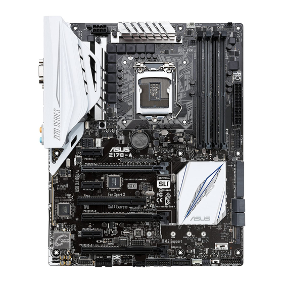
Place this side towards the rear of the chassis 1.2.3 Motherboard layout Chapter 1: Product Introduction…
-
Page 15: Layout Contents
Serial port connector (10-1 pin COM) 1-23 Front panel audio connector (10-1 pin AAFP) 1-27 Digital audio connector (4-1 pin SPDIF_OUT) 1-27 Flashback header (12-1 pin FLBK_HEADER) 1-33 T_Sensor connector (2-pin T_SENSOR) 1-32 CPU Over Voltage jumper (3-pin CPU_OV) 1-20 ASUS Z170-A Series…
-
Page 16: Central Processing Unit (Cpu)
Contact your retailer immediately if the PnP cap is missing, or if you see any damage to the PnP cap/socket contacts/motherboard components. ASUS will shoulder the cost of repair only if the damage is shipment/ transit-related.
-
Page 17: Installing The Cpu
1.3.1 Installing the CPU Top of CPU Bottom of CPU Bottom of CPU ASUS Z170-A Series…
-
Page 18
Top of CPU Chapter 1: Product Introduction… -
Page 19: Cpu Heatsink And Fan Assembly Installation
1.3.2 CPU heatsink and fan assembly installation Apply the Thermal Interface Material to the CPU heatsink and CPU before you install the heatsink and fan, if necessary. To install the CPU heatsink and fan assembly ASUS Z170-A Series…
-
Page 20: System Memory
To uninstall the CPU heatsink and fan assembly System memory 1.4.1 Overview The motherboard comes with four Double Data Rate 4 (DDR4) Dual Inline Memory Modules (DIMM) slots. A DDR4 module is notched differently from a DDR, DDR2, or DDR3 module. DO NOT install a DDR, DDR2, or DDR3 memory module to the DDR4 slot.
-
Page 21
2.5 Ai Tweaker menu for manual memory frequency adjustment. • For system stability, use a more efficient memory cooling system to support a full memory load (4 DIMMs). • Visit the ASUS website at: www.asus.com for the latest QVL. ASUS Z170-A Series… -
Page 22
Z170-A Motherboard Qualified Vendors Lists (QVL) DDR4 3400 (O.C.) MHz capability Vendors Part No. Size SS/DS Chip Chip NO. Timing Voltage DIMM socket Brand support (Optional) CORSAIR CMD16GX4M4B3400C16 16GB(4GB*4) Samsung K4A4G085WD 16-18-18-38 1.35V • ver. 4.23 DDR4 3333 (O.C.) MHz capability Vendors Part No. Size Chip Chip NO. -
Page 23
CORSAIR CMD16GX4M4A2800C16(Ver4.23) 16GB(4GB*4) 16-18-18-36 • • • (XMP) CORSAIR CMD16GX4M4A2800C16(Ver5.29) 16GB(4GB*4) 16-18-18-36 • • • CORSAIR CMD32GX4M4A2800C16(Ver5.29) 32GB(8GB*4) 18-18-18-36 • • • (XMP) CORSAIR CMK16GX4M4A2800C16(Ver4.23) 16GB(4GB*4) 16-16-18-36 • • • (XMP) (continued on the next page) ASUS Z170-A Series 1-11… -
Page 24
DDR4 2800 (O.C.) MHz capability Vendors Part No. Size SS/DS Chip Chip Timing Voltage DIMM socket Brand support (Optional) CORSAIR CMK16GX4M4A2800C16(Ver5.29) 16GB(4GB*4) 16-18-18-36 • • • CORSAIR CMK32GX4M4A2800C16(Ver5.29) 32GB(8GB*4) 16-18-18-36 • • • (XMP) G.SKILL F4-2800C15Q2-64GRK(XMP) 64GB(8GB*8) 15-16-16-35 1.25 • •… -
Page 25
• • • (4GB*4) Panram PUD42400C158G4NJW 32GB 15-15-15-35 • • • (8GB*4) Team TED44GM2400C16BK Samsung K4A4G085WD 16-16-16-39 • • • Team TED48GM2400C16BK Samsung K4A4G085WD 16-16-16-39 • • • V-color TD4G8C17-UH V-color DW3J0460HM 15-15-15-36 • • • ASUS Z170-A Series 1-13… -
Page 26
DDR4 2133 MHz capability Vendors Part No. Size SS/DS Chip Chip NO. Timing Voltage DIMM socket Brand support (Optional) ADATA AD4U2133W4G15-B SK Hynix H5AN4G8NMFRTFC 15-15-15-36 • • • ADATA AD4U2133W8G15 SK Hynix H5AN4G8NMFRTFC 15-15-15-36 • • • Apacer 78.B1GM3.AF00B SK Hynix H5AN4G8NMFRTFC 15-15-15-36 •… -
Page 27: Dimm Installation
1.4.3 DIMM installation ASUS Z170-A Series 1-15…
-
Page 28: Expansion Slots
To remove a DIMM Expansion slots In the future, you may need to install expansion cards. The following sub-sections describe the slots and the expansion cards that they support. Unplug the power cord before adding or removing expansion cards. Failure to do so may cause you physical injury and damage motherboard components.
-
Page 29: Pci Slot
PCI Express specifications. Slot No. Expansion slot PCIe 3.0/2.0 x1_1 slot PCIe 3.0/2.0 x16_1 slot PCIe 3.0/2.0 x1_2 slot PCI slot PCIe 3.0/2.0 x16_2 slot PCIe 3.0/2.0 x1_3 slot PCIe 3.0/2.0 x16_3 slot ASUS Z170-A Series 1-17…
-
Page 30: Irq Assignments For This Motherboard
PCI Express 3.0 operating mode VGA configuration PCIe 3.0/2.0 x16_1 PCIe 3.0/2.0 x16_2 x16 (single VGA Single VGA/PCIe card recommended) Dual VGA/PCIe card • We recommend that you provide sufficient power when running CrossFireX™ or SLI™ mode. • Connect a chassis fan to the motherboard connector labeled CHA_FAN1-4 when using multiple graphics cards for better thermal environment.
-
Page 31: Jumpers
• Due to chipset behavior, AC power off is required to enable C.P.R. function. You must turn off and on the power supply or unplug and plug the power cord before rebooting the system. ASUS Z170-A Series 1-19…
-
Page 32
CPU Over Voltage jumper (3-pin CPU_OV) The CPU Over Voltage jumper allows you to set a higher CPU voltage for a flexible overclocking system, depending on the type of the installed CPU. To gain more CPU voltage setting, insert the jumper to pins 2-3. To go back to its default CPU voltage setting, insert the jumper to pins 1-2. -
Page 33: Connectors
USB 3.0 ports 56 (supports USB 3.1 Boost) VGA port USB Type-C port EC1 (supports USB 3.1 Boost) PS/2 keyboard/mouse port LAN_USB31_EA2 (supports USB 3.1 Boost) LAN port* Optical S/PDIF Out port HDMI port Audio I/O ports** * and **: Refer to the tables on the next page for LAN port LEDs and audio port definitions. ASUS Z170-A Series 1-21…
-
Page 34
• The plugged USB 3.0 device will run on xHCI mode. • USB 3.0 devices can only be used for data storage. • We strongly recommend that you connect USB 3.0 devices to USB 3.0 ports for faster and better performance from your USB 3.0 devices. •… -
Page 35: Internal Connectors
This connector is for a serial (COM) port. Connect the serial port module cable to this connector, then install the module to a slot opening at the back of the system chassis. The COM module is purchased separately. ASUS Z170-A Series 1-23…
-
Page 36
Intel Z170 Serial ATA 6.0 Gb/s connectors (7-pin SATA6G_12, SATA6G_34, ® SATA6G_56, SATA Express) These connectors connect to Serial ATA 6 Gb/s hard disk drives via Serial ATA 6 Gb/s signal cables. If you installed Serial ATA hard disk drives, you can create a RAID 0, 1, 5, and 10 configuration with the Intel Rapid Storage Technology through the onboard Intel ®… -
Page 37
The CPU_FAN connector supports the CPU fan of maximum 1A (12 W) fan power. • W_PUMP function support depends on water cooling device. • The CPU_FAN connector and CHA_FAN connectors support the ASUS FAN Xpert 3 feature. • The CPU fan connector detects the type of CPU fan installed and automatically switches the control modes. -
Page 38
1000W power or above to ensure the system stability. • If you are uncertain about the minimum power supply requirement for your system, refer to the Recommended Power Supply Wattage Calculator at http://support.asus. com/PowerSupplyCalculator/PSCalculator.aspx?SLanguage=en-us for details. 1-26 Chapter 1: Product Introduction… -
Page 39
This connector is for an additional Sony/Philips Digital Interface (S/PDIF) port. Connect the S/PDIF Out module cable to this connector, then install the module to a slot opening at the back of the system chassis. The S/PDIF module is purchased separately. ASUS Z170-A Series 1-27… -
Page 40
DirectKey connector (2-pin DRCT) This connector is for the chassis-mounted button that supports the DirectKey function. Connect the button cable that supports DirectKey, from the chassis to this connector on the motherboard. Ensure that your chassis comes with the extra button cable that supports the DirectKey feature. -
Page 41
TPM connector (14-1 pin TPM) This connector supports a Trusted Platform Module (TPM) system, which securely store keys, digital certificates, passwords and data. A TPM system also helps enhance network security, protects digital identities, and ensures platform integrity. ASUS Z170-A Series 1-29… -
Page 42: System Panel Connector
System panel connector (20-3 pin PANEL) This connector supports several chassis-mounted functions. • System power LED (2-pin or 3-pin PWR_LED) The 2-pin or 3-pin connector is for the system power LED. Connect the chassis power LED cable to this connector. The system power LED lights up when you turn on the system power, and blinks when the system is in sleep mode.
-
Page 43
• The plugged USB 3.0 device will run on xHCI mode. • These USB 3.0 ports support native UASP transfer standard in Windows ® Windows 8.1 and Turbo Mode when using USB 3.0 Boost feature. ® ASUS Z170-A Series 1-31… -
Page 44
Thunderbolt header (5-pin TB_HEADER) This connector is for the add-on Thunderbolt I/O card that supports Intel’s Thunderbolt Technology, allowing you to connect up to six Thunderbolt-enabled devices and a DisplayPort-enabled display in a daisy-chain configuration. The add-on Thunderbolt I/O card and Thunderbolt cables are purchased separately. T_Sensor connector (2-pin T_SENSOR) This connector is for the thermistor cable that allows you to monitor the temperature of your motherboard’s critical components and connected devices. -
Page 45
Flashback header (12-1 pin FLBK_HEADER) This connector is for the USB BIOS Flashback card that allows you to easily update the BIOS without entering the existing BIOS or operating system. The USB BIOS Flashback card is purchased separately. ASUS Z170-A Series 1-33… -
Page 46: Onboard Leds
Onboard LEDs Standby Power LED The motherboard comes with a standby power LED that lights up to indicate that the system is ON, in sleep mode, or in soft-off mode. This is a reminder that you should shut down the system and unplug the power cable before removing or plugging any motherboard components.
-
Page 47
This LED lights up when you enable the EZ XMP switch. LED Design These LEDs light up when the system is fully powered and operating. To turn off the LEDs, refer to BIOS section 2.6.8 Onboard Devices Configuration > LED Design Switch for details. ASUS Z170-A Series 1-35… -
Page 48: Onboard Buttons And Switches
BIOS default settings. A message will appear during POST reminding you that the BIOS has been restored to its default settings. • We recommend that you download and update to the latest BIOS version from www.asus.com after using the MemOK! function. 1-36 Chapter 1: Product Introduction…
-
Page 49
You may use the 5-Way Optimization and TPU feature in the AI Suite 3 application, adjust the BIOS setup program or enable the TPU switch at the same time. However, the system will use the last setting you have made. ASUS Z170-A Series 1-37… -
Page 50
Power-on button The motherboard comes with a power-on button that allows you to power up or wake up the system. The button also lights up when the system is plugged to a power source indicating that you should shut down the system and unplug the power cable before removing or installing any motherboard component. -
Page 51: Software Support
Place the Support DVD into the optical drive. If Autorun is enabled in your computer, the DVD automatically displays the lists of the unique features of your ASUS motherboard. Click the Drivers, Utilities, AHCI/RAID Driver, Manual, Contact, or Specials tabs to display their respective menus.
-
Page 52
1-40 Chapter 1: Product Introduction… -
Page 53: Chapter 2: Bios Setup
BIOS Setup Knowing BIOS The new ASUS UEFI BIOS is a Unified Extensible Interface that complies with UEFI architecture, offering a user-friendly interface that goes beyond the traditional keyboard- only BIOS controls to enable a more flexible and convenient mouse input. You can easily navigate the new UEFI BIOS with the same smoothness as your operating system.
-
Page 54: Bios Setup Program
BIOS setup program Use the BIOS Setup to update the BIOS or configure its parameters. The BIOS screen include navigation keys and brief onscreen help to guide you in using the BIOS Setup program. Entering BIOS at startup To enter BIOS Setup at startup, press <Delete> during the Power-On Self Test (POST). If you do not press <Delete>, POST continues with its routines.
-
Page 55: Ez Mode
Click to go to Advanced mode Loads optimized Search on the FAQ default settings Click to display boot devices Selects the boot device priority The boot device options vary depending on the devices you installed to the system. ASUS Z170-A Series…
-
Page 56: Advanced Mode
2.2.2 Advanced Mode The Advanced Mode provides advanced options for experienced end-users to configure the BIOS settings. The figure below shows an example of the Advanced Mode. Refer to the following sections for the detailed configurations. To switch from EZ Mode to Advanced Mode, click Advanced Mode or press <F7> hotkey. Configuration fields Quick Note (F9) Pop-up Menu…
-
Page 57: Menu Bar
This button above the menu bar allows you to view and tweak the overclocking settings of your system. It also allows you to change the motherboard’s SATA mode from AHCI to RAID mode. Refer to section 2.2.4 EZ Tuning Wizard for more information. ASUS Z170-A Series…
-
Page 58: Hot Keys
Move your mouse over this button to show a QR code, scan this QR code on your mobile device to connect to the BIOS FAQ web page of the ASUS support website. You can also scan the following QR code:…
-
Page 59: Qfan Control
Click to activate DC Mode configured PWM Mode Select a profile to apply to Click to apply the fan setting your fans Click to undo the Click to go back to main menu changes Select to manually configure your fans ASUS Z170-A Series…
-
Page 60: Configuring Fans Manually
Configuring fans manually Select Manual from the list of profiles to manually configure your fans’ operating speed. Speed points Select to manually configure your fans To configure your fans: Select the fan that you want to configure and to view its current status. Click and drag the speed points to adjust the fans’…
-
Page 61: Ez Tuning Wizard
To start OC Tuning: Press <F11> on your keyboard or click from the BIOS screen to open EZ Tuning Wizard screen. Click OC then click Next. Select a PC scenario Daily Computing or Gaming/Media Editing, then click Next. ASUS Z170-A Series…
-
Page 62: Creating Raid
Select a Main Cooling System BOX cooler, Tower cooler, Water cooler, or I’m not sure, then click Next. After selecting the Main Cooling System, click Next then click Yes to start the OC Tuning. Creating RAID To create RAID: Press <F11> on your keyboard or click from the BIOS screen to open EZ Tuning Wizard screen.
-
Page 63
Speed (RAID5). After selecting the type of RAID, click Next then click Yes to continue the RAID setup. After the RAID setup is done, click Yes to exit the setup then click OK to reset your system. ASUS Z170-A Series 2-11… -
Page 64: My Favorites
My Favorites My Favorites is your personal space where you can easily save and access your favorite BIOS items. My Favorites comes with several performance, power saving, and fast boot related items by default. You can personalize this screen by adding or removing items. Chapter 2: BIOS Setup 2-12…
-
Page 65: Adding Items To My Favorites
• Configuration items such as Memory SPD Information, system time and date. Click Exit (ESC) or press <Esc> key to close Setup Tree Map screen. Go to My Favorites menu to view the saved BIOS items. ASUS Z170-A Series 2-13…
-
Page 66: Main Menu
Main menu The Main menu screen appears when you enter the Advanced Mode of the BIOS Setup program. The Main menu provides you an overview of the basic system information, and allows you to set the system date, time, language, and security settings. Security The Security menu items allow you to change the system security settings.
-
Page 67: Administrator Password
[Installed.] To set a user password: Select the User Password item and press <Enter>. From the Create New Password box, key in a password, then press <Enter>. Confirm the password when prompted. ASUS Z170-A Series 2-15…
-
Page 68: Ai Tweaker Menu
To change a user password: Select the User Password item and press <Enter>. From the Enter Current Password box, key in the current password, then press <Enter>. From the Create New Password box, key in a new password, then press <Enter>. Confirm the password when prompted.
-
Page 69
Use the <+> or <-> to adjust the value. The values range from 40.0 MHz to 500.0 MHz. We recommend you to set the value based on the CPU specification, as high BCLK frequencies may damage the CPU permanently. ASUS Z170-A Series 2-17… -
Page 70
ASUS MultiCore Enhancement [Auto] [Auto] This item allows you to maximize the oveclocking performance optimized by ASUS core ratio settings. [Disabled] This item allows you to set to default core ratio settings. CPU Core Ratio [Auto] This item allows you to set the CPU core ratio limit per core or synchronize automatically to all cores. -
Page 71: Dram Timing Control
Applies water cooling overclocking conditions. Ensure to use water cooling device before selecting [TPU II]. EPU Power Saving Mode [Disabled] The ASUS EPU (Energy Processing Unit) sets the CPU in its minimum power consumption settings. Configuration options: [Disabled] [Enabled] CPU SVID Support Disable this item to stop the CPU from communicating with the external voltage regulator.
-
Page 72
Primary Timings DRAM CAS# Latency [Auto] Configuration options: [Auto] [1] – [31] DRAM RAS# to CAS# Delay [Auto] Configuration options: [Auto] [1] – [31] DRAM RAS# ACT Time [Auto] Configuration options: [Auto] [1] – [63] DRAM COMMAND Rate [Auto] Configuration options: [Auto] [1] – [2] Secondary Timings DRAM RAS# to RAS# Delay L [Auto] Configuration options: [Auto] [1] –… -
Page 73
Configuration options: [Auto] [0] — [15] Data Falling Slope Offset [Auto] Configuration options: [Auto] [0] — [1] CMD Falling Slope [Auto] Configuration options: [Auto] [0] — [15] CMD FallingSlope Offset [Auto] Configuration options: [Auto] [0] — [1] ASUS Z170-A Series 2-21… -
Page 74
Ctl Falling Slope [Auto] Configuration options: [Auto] [0] — [15] Ctl Falling Slope Offset [Auto] Configuration options: [Auto] [0] — [1] Clk Falling Slope [Auto] Configuration options: [Auto] [0] — [15] Clk Falling Slope Offset [Auto] Configuration options: [Auto] [0] — [1] RTL IOL control DRAM RTL INIT Value [Auto] Configuration options: [Auto] [0] — [127]… -
Page 75
Configuration options: [Auto] [0] — [63] tRDWR_dr [Auto] Configuration options: [Auto] [0] — [63] tRDWR_dd [Auto] Configuration options: [Auto] [0] — [63] tWRWR_dr [Auto] Configuration options: [Auto] [0] — [63] tWRWR_dd [Auto] Configuration options: [Auto] [0] — [63] ASUS Z170-A Series 2-23… -
Page 76
tWRRD_dr [Auto] Configuration options: [Auto] [0] — [63] tWRRD_dd[Auto] Configuration options: [Auto] [0] — [63] TWRPRE [Auto] Configuration options: [Auto] [0] — [127] TRDPRE [Auto] Configuration options: [Auto] [0] — [15] tREFIX9 [Auto] Configuration options: [Auto] [0] — [127] OREF_RI[Auto] Configuration options: [Auto] [0] –… -
Page 77
Use the <+> or <-> to adjust the value. The values range from 300 KHz to 600 KHz with an interval of 50 KHz. Do not remove the thermal module when the manual mode is selected. The thermal conditions should be monitored. ASUS Z170-A Series 2-25… -
Page 78
The following item appears only when the CPU VRM Switching Frequency is set to [Auto]. VRM Spread Spectrum [Disabled] This item allows to enhance the system stability. Configuration options: [Disabled] [Enabled] CPU Power Duty Control [T.Probe] DIGI + VRM Duty Control adjusts the current of every VRM phase and the thermal conditions of every phase component. -
Page 79
Configuration options: [Auto] [0.7000] — [1.8000] CPU VCCIO Boot Voltage [Auto] Configuration options: [Auto] [0.7000] — [1.8000] CPU Standby Boot Voltage [Auto] The voltage for CPU standby at initial Boot. Configuration options: [Auto] [0.7000] — [1.8000] [0.700~2.200] ASUS Z170-A Series 2-27… -
Page 80
Internal CPU Power Management The subitems in this menu allow you to set the CPU ratio and features. Intel(R) SpeedStep(tm) [Enabled] Allows the operating system to dynamically adjust the processor voltage and cores frequency to decrease the average power consumption and decrease average heat production. -
Page 81
CPU Core/Cache Current Limit Max. [Auto] This item allows you to configure a higher current limit to prevent a frequency or power throttling when overclocking. Use the <+> and <-> keys to adjust the value. Configuration options: [Auto] [0.00] — [255.50] ASUS Z170-A Series 2-29… -
Page 82
CPU Graphics Current Limit Max. [Auto] This item allows you to set a higher current limit to prevent a frequency or power throttling when overclocking. Use the <+> and <-> keys to adjust the value. Configuration options: [Auto] [0.00] — [255.50] Min. -
Page 83
DRAM DATA REF Voltage on CHB DIMM1 Rank0 BL0-7 [Auto] Configures the DRAM Data REF Voltage. Configuration options: [Auto] [0] — [63] DRAM DATA REF Voltage on CHB DIMM1 Rank1 BL0-7 [Auto] Configures the DRAM Data REF Voltage. Configuration options: [Auto] [0] — [63] ASUS Z170-A Series 2-31… -
Page 84: Advanced Menu
Advanced menu The Advanced menu items allow you to change the settings for the CPU and other system devices. Be cautious when changing the settings of the Advanced menu items. Incorrect field values can cause the system to malfunction. Chapter 2: BIOS Setup 2-32…
-
Page 85: Cpu Configuration
This item allows you to select the number of CPU cores to activate in each processor package. Configuration options: [All] [1] [2] [3] Intel Virtualization Technology [Enabled] When set to [Enabled], a VMM can utilize the additional hardware capabilities provided by Vanderpool Technology. Configuration options: [Disabled] [Enabled] ASUS Z170-A Series 2-33…
-
Page 86
Hardware Prefetcher [Enabled] This item allows the CPU to prefetch commands and data in the L2 cache, reduces the DRAM loading time and improves the system performance. Configuration options: [Disabled] [Enabled] Adjacent Cache Line Prefetcher [Enabled] This item allows the mid level cache (L2) to prefetch adjacent cache lines, reducing the DRAM loading time and improves the system performance. -
Page 87: Platform Misc Configuration
The following item appears only when you set the PCI Express Native Power Management to [Enabled]. Native ASPM [Disabled] [Enabled] Windows Vista OS controls the ASPM (active state power ® management) support for devices. [Disabled] BIOS controls the ASPM support for the device. ASUS Z170-A Series 2-35…
-
Page 88
ASPM to take effect. Configuration options: [Disabled] [L1] PEG ASPM Support [Disabled] This item allows you to select the ASPM state for energy-saving conditions, or use the ASUS optimized energy saving profile. Configuration options: [Disabled] [Auto] [ASPM L0s] [ASPM L1] [ASPM L0sL1]… -
Page 89: System Agent (Sa) Configuration
PCIEx16_1 Link Speed [Auto] This item allows you to configure the PCIEx16_1 slot. Configuration options: [Auto] [Gen1] [Gen2] [Gen3] PCIEx16_2 Link Speed [Auto] This item allows you to configure the PCIEx16_2 slot. Configuration options: [Auto] [Gen1] [Gen2] [Gen3] ASUS Z170-A Series 2-37…
-
Page 90: Pch Configuration
2.6.4 PCH Configuration PCI Express Configuration This item allows you to configure the PCI Express slots. PCIe Speed [Auto] This item allows your system to automatically select the PCI Express port speed. Configuration options: [Auto] [Gen1] [Gen2] [Gen3] 2.6.5 PCH Storage Configuration While entering Setup, the BIOS automatically detects the presence of SATA devices.
-
Page 91
This item allows you to enable or disable the selected SATA port. Configuration options: [Disabled] [Enabled] Hot Plug [Disabled] These items appears only when the SATA Mode Selection is set to [AHCI] and allows you to enable or disable SATA Hot Plug Support. Configuration options: [Disabled] [Enabled] ASUS Z170-A Series 2-39… -
Page 92: Usb Configuration
2.6.6 USB Configuration The items in this menu allow you to change the USB-related features. The Mass Storage Devices item shows the auto-detected values. If no USB device is detected, the item shows None. Legacy USB Support [Enabled] [Enabled] Your system supports the USB devices in legacy operating systems. [Disabled] Your USB devices can be used for BIOS setup only and cannot be recognized in the boot devices list.
-
Page 93: Network Stack Configuration
The following item appears only when you set the Network Stack to [Enabled]. Ipv4/Ipv6 PXE Support [Enabled] This item allows you to enable or disable the Ipv4/Ipv6 PXE wake event. Configuration options: [Disabled] [Enabled] 2.6.8 Onboard Devices Configuration Scroll down to view the other BIOS items. ASUS Z170-A Series 2-41…
-
Page 94
HD Audio Controller [Enabled] This item allows you to use the Azalia High Definition Audio Controller Configuration options: [Disabled] [Enabled] The following items appear only when you set the HD Audio Controller to [Enabled]. Front Panel Type [HD Audio] This item allows you to set the front panel audio connector (AAFP) mode to legacy AC’97 or high-definition audio depending on the audio standard that the front panel audio module supports. -
Page 95: Serial Port Configuration
This item allows you to enable/disable the serial port. Configuration options: [On] [Off] Change Settings [IO=3F8h; IRQ=4] This item allows you to select an optimal setting for Super IO device. Configuration options: [IO=3F8h; IRQ=4] [IO=2F8h; IRQ=3] [IO=3E8h; IRQ=4] [IO=2E8h; IRQ=3] ASUS Z170-A Series 2-43…
-
Page 96: Apm Configuration
2.6.9 APM Configuration ErP Ready [Disabled] This item allows you to switch off some power at S4+S5 or S5 to get the system ready for ErP requirement. When set to [Enabled], all other PME options are switched off. Configuration options: [Disabled] [Enabled (S4+S5] [Enabled (S5)] Restore AC Power Loss [Power Off] This item allows your system to go to ON state, OFF state, or both states after an AC power loss.
-
Page 97: Hdd/Ssd Smart Information
This item allows you to disable or enable the Intel Thunderbolt Technology. Configuration options: [Fully Disabled] [Disabled] [Enabled] ThunderBolt Boot Support [Disabled] This item allows you to disable or enable the ThunderBolt Boot Support. Configuration options: [Disabled] [Enabled] ASUS Z170-A Series 2-45…
-
Page 98: Monitor Menu
Monitor menu The Monitor menu displays the system temperature/power status, and allows you to change the fan settings. Scroll down to display the other BIOS items. CPU Temperature / MB Temperature / VRM Temperature / PCH Core Temperature / T_SENSOR1 Temperature / EXT_SENSOR1-3 Temperature [xxx°C/xxx°F] The onboard hardware monitor automatically detects and displays the CPU, motherboard, [Ignore]…
-
Page 99
CPU fan will operate at the maximum duty cycle. CPU Middle Temperature [25] Use the <+> or <-> keys to adjust the middle limit of the CPU temperature. The values range from 20 to 75. ASUS Z170-A Series 2-47… -
Page 100
CPU Fan Middle. Duty Cycle (%) [20] Use the <+> or <-> keys to adjust the maximum CPU fan duty cycle. The values range from 20% to 100%. When the CPU temperature reaches the upper limit, the CPU fan will operate at the maximum duty cycle. CPU Lower Temperature [20] Use the <+>… -
Page 101
The values range from 0% to 100%. When the CPU temperature is under the limit, the Chassis Fan 1-4 fan will operate at the minimum duty cycle. ASUS FAN EXTENSION CARD is required to configure these items Extension Fan 1-3 Q-Fan Control [DC Mode] [Disabled] Disable the Extension Fan Q-Fan control feature. -
Page 102
Extension Fan 1-3 Profile [Standard] This item allows you to set the appropriate performance level of the CPU fan. [Standard] Set to make the CPU fan adjust automatically depending on the CPU temperature. [Silent] Set to minimize the fan speed for quiet CPU fan operation. [Turbo] Set to achieve maximum CPU fan speed. -
Page 103: Boot Menu
Anti Surge Support [On] Enable this item for Over Voltage Protection (OVP) and Under Voltage Protection (UVP) functions. Configuration options: [On] [Off] Boot menu The Boot menu items allow you to change the system boot options. ASUS Z170-A Series 2-51…
-
Page 104
Fast Boot [Enabled] [Disabled] Allows your system to go back to its normal boot speed. [Enabled] Allows your system to accelerate the boot speed. The following items appear only when you set the Fast Boot to [Enabled]. SATA Support [HDD Only] [All Sata Devices] All devices connected to SATA ports are available during POST. -
Page 105
Configuration options: [Disabled] [Enabled] Option ROM Messages [Force BIOS] [Force BIOS] The Option ROM Messages will be shown during the POST. [Disabled] Only the ASUS logo will be shown during the POST. Interrupt 19 Capture [Disabled] [Enabled] Execute the trap right away. [Disabled] Execute the trap during legacy boot. -
Page 106: Secure Boot
CSM (Compatibility Support Module) This item allows you to configure the CSM (Compatibility Support Module) items to fully support the various VGA, bootable devices and add-on devices for better compatibility. Launch CSM [Enabled] [Auto] The system automatically detects the bootable devices and the add- on devices.
-
Page 107
Allows you to load the additional db from a storage device so that more images can be loaded securely. The db file must be formatted as a UEFI variable structure with time-based authenticated variable. DBX Management ASUS Z170-A Series 2-55… -
Page 108: Boot Option Priorities
OS in Safe Mode, press <F8> after POST (Windows 8 not supported). • To select the boot device during system startup, press <F8> when the ASUS Logo appears. Boot Override These items displays the available devices. The number of device items that appears on the screen depends on the number of devices installed in the system.
-
Page 109: Tool Menu
To launch Secure Erase, click Tool > Secure Erase on the Advanced mode menu. Check the ASUS support site for a full list of SSDs tested with Secure Erase. The drive may become unstable if you run Secure Erase on an incompatible SSD.
-
Page 110
Locked. SSDs might be locked if the Secure Erase process is either incomplete or was stopped. This may be due to a third party software that uses a different password defined by ASUS. You have to unlock the SSD in the software before proceeding with Secure Erase. -
Page 111: Asus O.c. Profile
Key in a profile number from one to eight, press <Enter>, and then select Yes. Load/Save Profile from/to USB Drive This item allows you to load or save profile from your USB drive, load and save profile to your USB drive. ASUS Z170-A Series 2-59…
-
Page 112: Asus Dram Spd Information
2.9.4 ASUS DRAM SPD Information This item allows you to view the DRAM SPD information. 2.9.5 Graphics Card Information This item displays the information about the graphics card installed in your system. GPU Post This item displays the information and recommended configuration for the PCIE slots that the graphics card is installed in your system.
-
Page 113: Exit Menu
<Esc>, a confirmation window appears. Select Yes to discard changes and exit. Launch EFI Shell from filesystem device This option allows you to attempt to launch the EFI Shell application (shellx64.efi) from one of the available filesystem devices. ASUS Z170-A Series 2-61…
-
Page 114: Updating Bios
® ASUS EZ Flash 3: Updates the BIOS using a USB flash drive. ASUS CrashFree BIOS 3: Restores the BIOS using the motherboard support DVD or a USB flash drive when the BIOS file fails or gets corrupted. 2.11.1 EZ Update EZ Update is a utility that allows you to automatically update your motherboard’s softwares,…
-
Page 115: Asus Ez Flash 3
2.11.2 ASUS EZ Flash 3 ASUS EZ Flash 3 allows you to download and update to the latest BIOS through the Internet without having to use a bootable floppy disk or an OS-based utility. Updating through the Internet varies per region and Internet conditions. Check your local Internet connection before updating through the Internet.
-
Page 116
To update the BIOS by Internet: Enter the Advanced Mode of the BIOS setup program. Go to the Tool menu to select ASUS EZ Flash Utility and press <Enter>. Select by Internet. Press the Left/Right arrow keys to select an Internet connection method, and then press <Enter>. -
Page 117: Asus Crashfree Bios 3
The BIOS file in the motherboard support DVD may be older than the BIOS file published on the ASUS official website. If you want to use the newer BIOS file, download the file at http://support.asus.com and save it to a USB flash drive.
-
Page 118: Installing An Operating System
Connect the USB ODD or USB storage device to your 100 series platform. Insert the ASUS support DVD into a SATA ODD on your 100 series platform. Power on your system and press F8 during POST (Power-On Self Test) to enter the boot screen.
-
Page 119
The USB 3.0 driver will be loaded automatically during installation startup. The “Setup is starting…” screen will show up if the USB 3.0 driver is loaded correctly. Follow the onscreen instructions to complete the Windows 7 installation. ® ASUS Z170-A Series 2-67… -
Page 120
® source using a third-party ISO software. Copy both “Auto_Unattend.xml” and “Auto_Unattend” folder from the root directory of the ASUS supporting DVD to your system. Edit the ISO file and add both “Auto_Unattend.xml” and “Auto_Unattend” folder into the ISO file. -
Page 121
1 x USB storage device (8 GB or more) Insert the Windows 7 installation DVD. ® Launch the ASUS EZ Installer located on the ASUS support DVD. Select a method of creating a modified Windows 7 installation file: ® •… -
Page 122
7 installation disk then click Next. — Select the source of the Windows ® — Select the USB storage device and click next. Click the refresh icon if the USB storage device is not displayed. — Click Yes to clear the contents on the USB storage device and create a bootable USB device. -
Page 123
7 OS disk to ISO file ® — Select Windows 7 OS disk to ISO file then click Next. — Check I agree and then click Next. — Select the source of the Windows 7 installation disk then click Next. ® ASUS Z170-A Series 2-71… -
Page 124
— Select the folder to save the modified Windows 7 installation ISO file and click ® Next. — Once completed, click OK to finish. — Burn this ISO file onto an empty DVD to create a modified Windows ® installation DVD. Insert the modified Windows 7 installation DVD into an ODD or connect the USB ®… -
Page 125: Appendices
Consult the dealer or an experienced radio/TV technician for help. The use of shielded cables for connection of the monitor to the graphics card is required to assure compliance with FCC regulations. Changes or modifications to this unit not expressly approved by the party responsible for compliance could void the user’s authority to operate this equipment. ASUS Z170-A Series…
-
Page 126: Canadian Department Of Communications Statement
IC: Canadian Compliance Statement Complies with the Canadian ICES-003 Class B specifications. This device complies with RSS 210 of Industry Canada. This Class B device meets all the requirements of the Canadian interference-causing equipment regulations. This device complies with Industry Canada license exempt RSS standard(s). Operation is subject to the following two conditions: (1) this device may not cause interference, and (2) this device must accept any interference, including interference that may cause undesired operation of the device.
-
Page 127
ASUS Recycling/Takeback Services ASUS recycling and takeback programs come from our commitment to the highest standards for protecting our environment. We believe in providing solutions for you to be able to responsibly recycle our products, batteries, other components as well as the packaging materials. -
Page 128
Slovenščina AsusTek Inc. tukaj izjavlja, da je ta naprava skladna s di conformità CE. temeljnimi zahtevami in drugimi relevantnimi določili direktiv CE. Za več Компания ASUS заявляет, что это устройство соответствует основным informacij glejte Izjavo CE o skladnosti. требованиям и другим соответствующим условиям европейских… -
Page 129: Asus Contact Information
+1-510-739-3777 +1-510-608-4555 Web site http://www.asus.com/us/ Technical Support Support fax +1-812-284-0883 Telephone +1-812-282-2787 Online support http://www.service.asus.com/ ASUS COMPUTER GmbH (Germany and Austria) Address Harkort Str. 21-23, D-40880 Ratingen, Germany +49-2102-959911 Web site http://www.asus.com/de Online contact http://eu-rma.asus.com/sales Technical Support Telephone +49-1805-010923 Support Fax…
-
Page 130
Appendices…
- Инструкции и руководства
- Бренды
- ASUS
- Z170-A
- Справочник Пользователя
![]()
-
Драйверы
43
-
Инструкции по эксплуатации
6
Языки:

ASUS Z170-A инструкция по эксплуатации
(6 страниц)
- Языки:Английский
-
Тип:
PDF -
Размер:
1.26 MB -
Описание:
Win7 Installation guide(English)
Просмотр

ASUS Z170-A инструкция по эксплуатации
(122 страницы)
- Языки:Японский
-
Тип:
PDF -
Размер:
6.35 MB -
Описание:
Z170-A User’s manual (Japanese)
Z170-A User’s manual (Japanese)
Просмотр

ASUS Z170-A инструкция по эксплуатации
(130 страниц)
- Языки:Испанский
-
Тип:
PDF -
Размер:
9.69 MB -
Описание:
Z170-A User’s manual (Spanish)
Просмотр

ASUS Z170-A инструкция по эксплуатации
(8 страниц)
- Языки:Японский
-
Тип:
PDF -
Размер:
1.67 MB -
Описание:
Win7 Installation guide(Japanese)
Просмотр

ASUS Z170-A инструкция по эксплуатации
(6 страниц)
- Языки:Немецкий
-
Тип:
PDF -
Размер:
509.59 KB -
Описание:
Win7 Installation guide(German)
Просмотр

ASUS Z170-A инструкция по эксплуатации
(6 страниц)
- Языки:Французский
-
Тип:
PDF -
Размер:
655.89 KB -
Описание:
Win7 Installation guide(French)
Просмотр
На NoDevice можно скачать инструкцию по эксплуатации для ASUS Z170-A. Руководство пользователя необходимо для ознакомления с правилами установки и эксплуатации ASUS Z170-A. Инструкции по использованию помогут правильно настроить ASUS Z170-A, исправить ошибки и выявить неполадки.
 Loading…
![]()

E10611
Revised Edition V2
July 2015
Copyright © 2015 ASUSTeK COMPUTER INC. All Rights Reserved.
No part of this manual, including the products and software described in it, may be reproduced, transmitted, transcribed, stored in a retrieval system, or translated into any language in any form or by any means, except documentation kept by the purchaser for backup purposes, without the express written permission of ASUSTeK COMPUTER INC. (“ASUS”).
Product warranty or service will not be extended if: (1) the product is repaired, modified or altered, unless such repair, modification of alteration is authorized in writing by ASUS; or (2) the serial number of the product is defaced or missing.
ASUS PROVIDES THIS MANUAL “AS IS” WITHOUT WARRANTY OF ANY KIND, EITHER EXPRESS OR IMPLIED, INCLUDING BUT NOT LIMITED TO THE IMPLIED WARRANTIES OR CONDITIONS OF MERCHANTABILITY OR FITNESS FOR A PARTICULAR PURPOSE. IN NO EVENT SHALL ASUS, ITS DIRECTORS, OFFICERS, EMPLOYEES OR AGENTS BE LIABLE FOR ANY INDIRECT, SPECIAL, INCIDENTAL, OR CONSEQUENTIAL DAMAGES (INCLUDING DAMAGES FOR LOSS OF PROFITS, LOSS OF BUSINESS, LOSS OF USE OR DATA, INTERRUPTION OF BUSINESS AND THE LIKE), EVEN IF ASUS HAS BEEN ADVISED OF THE POSSIBILITY OF SUCH DAMAGES ARISING FROM ANY DEFECT OR ERROR IN THIS MANUAL OR PRODUCT.
SPECIFICATIONS AND INFORMATION CONTAINED IN THIS MANUAL ARE FURNISHED FOR INFORMATIONAL USE ONLY, AND ARE SUBJECT TO CHANGE AT ANY TIME WITHOUT NOTICE, AND SHOULD NOT BE CONSTRUED AS A COMMITMENT BY ASUS. ASUS ASSUMES NO RESPONSIBILITY OR LIABILITY FOR ANY ERRORS OR INACCURACIES THAT MAY APPEAR IN THIS MANUAL, INCLUDING THE PRODUCTS AND SOFTWARE DESCRIBED IN IT.
Products and corporate names appearing in this manual may or may not be registered trademarks or copyrights of their respective companies, and are used only for identification or explanation and to the owners’ benefit, without intent to infringe.
Offer to Provide Source Code of Certain Software
This product contains copyrighted software that is licensed under the General Public License (“GPL”), under the Lesser General Public License Version (“LGPL”) and/or other Free Open Source Software Licenses. Such software in this product is distributed without any warranty to the extent permitted by the applicable law. Copies of these licenses are included in this product.
Where the applicable license entitles you to the source code of such software and/or other additional data, you may obtain it for a period of three years after our last shipment of the product, either
(1)for free by downloading it from http://support.asus.com/download
or
(2)for the cost of reproduction and shipment, which is dependent on the preferred carrier and the location where you want to have it shipped to, by sending a request to:
ASUSTeK Computer Inc.
Legal Compliance Dept.
15 Li Te Rd.,
Beitou, Taipei 112
Taiwan
In your request please provide the name, model number and version, as stated in the About Box of the product for which you wish to obtain the corresponding source code and your contact details so that we can coordinate the terms and cost of shipment with you.
The source code will be distributed WITHOUT ANY WARRANTY and licensed under the same license as the corresponding binary/object code.
This offer is valid to anyone in receipt of this information.
ASUSTeK is eager to duly provide complete source code as required under various Free Open Source Software licenses. If however you encounter any problems in obtaining the full corresponding source code we would be much obliged if you give us a notification to the email address gpl@asus.com, stating the product and describing the problem (please DO NOT send large attachments such as source code archives, etc. to this email address).
ii

Contents
|
Safety information…………………………………………………………………………………………. |
v |
|
About this guide…………………………………………………………………………………………….. |
v |
|
Package contents………………………………………………………………………………………… |
vii |
|
Z170-A specifications summary……………………………………………………………………. |
vii |
|
Chapter 1: |
Product Introduction |
||
|
1.1 |
Before you proceed………………………………………………………………………… |
1-1 |
|
|
1.2 |
Motherboard overview……………………………………………………………………. |
1-1 |
|
|
1.3 |
Central Processing Unit (CPU)………………………………………………………… |
1-4 |
|
|
1.4 |
System memory……………………………………………………………………………… |
1-8 |
|
|
1.5 |
Expansion slots……………………………………………………………………………. |
1-16 |
|
|
1.6 |
Jumpers |
……………………………………………………………………………………….. |
1-19 |
|
1.7 |
Connectors…………………………………………………………………………………… |
1-21 |
|
|
1.8 |
Onboard ……………………………………………………………………………….LEDs |
1-34 |
|
|
1.9 |
Onboard ………………………………………………………buttons and switches |
1-36 |
|
|
1.10 |
Software …………………………………………………………………………..support |
1-39 |
|
Chapter 2: |
BIOS Setup |
||
|
2.1 |
Knowing BIOS………………………………………………………………………………… |
2-1 |
|
|
2.2 |
BIOS setup program……………………………………………………………………….. |
2-2 |
|
|
2.2.1 |
EZ Mode………………………………………………………………………….. |
2-3 |
|
|
2.2.2 |
Advanced Mode………………………………………………………………… |
2-4 |
|
|
2.2.3 |
QFan Control……………………………………………………………………. |
2-7 |
|
|
2.2.4 |
EZ Tuning Wizard……………………………………………………………… |
2-9 |
|
|
2.3 |
My Favorites…………………………………………………………………………………. |
2-12 |
|
|
2.4 |
Main menu……………………………………………………………………………………. |
2-14 |
|
|
2.5 |
Ai Tweaker menu………………………………………………………………………….. |
2-16 |
|
|
2.6 |
Advanced menu……………………………………………………………………………. |
2-32 |
|
|
2.6.1 |
CPU Configuration…………………………………………………………… |
2-33 |
|
|
2.6.2 |
Platform Misc Configuration………………………………………………. |
2-35 |
|
|
2.6.3 |
System Agent (SA) Configuration………………………………………. |
2-37 |
|
|
2.6.4 |
PCH Configuration…………………………………………………………… |
2-38 |
|
|
2.6.5 |
PCH Storage Configuration………………………………………………. |
2-38 |
|
|
2.6.6 |
USB Configuration…………………………………………………………… |
2-40 |
|
|
2.6.7 |
Network Stack Configuration…………………………………………….. |
2-41 |
|
|
2.6.8 |
Onboard Devices Configuration…………………………………………. |
2-41 |
|
|
2.6.9 |
APM Configuration…………………………………………………………… |
2-44 |
|
|
2.6.10 |
HDD/SSD SMART Information………………………………………….. |
2-45 |
|
|
2.6.11 |
Intel(R) Thunderbolt…………………………………………………………. |
2-45 |
iii

|
2.7 |
Monitor menu……………………………………………………………………………….. |
2-46 |
|
|
2.8 |
Boot menu……………………………………………………………………………………. |
2-51 |
|
|
2.9 |
Tool menu…………………………………………………………………………………….. |
2-57 |
|
|
2.9.1 |
ASUS EZ Flash 3 Utility……………………………………………………. |
2-57 |
|
|
2.9.2 |
Secure Erase………………………………………………………………….. |
2-57 |
|
|
2.9.3 |
ASUS O.C. Profile…………………………………………………………… |
2-59 |
|
|
2.9.4 |
ASUS DRAM SPD Information………………………………………….. |
2-60 |
|
|
2.9.5 |
Graphics Card Information………………………………………………… |
2-60 |
|
|
2.10 |
Exit menu……………………………………………………………………………………… |
2-61 |
|
|
2.11 |
Updating BIOS……………………………………………………………………………… |
2-62 |
|
|
2.11.1 |
EZ Update………………………………………………………………………. |
2-62 |
|
|
2.11.2 |
ASUS EZ Flash 3…………………………………………………………….. |
2-63 |
|
|
2.11.3 |
ASUS CrashFree BIOS 3…………………………………………………. |
2-65 |
|
|
2.12 |
Installing an operating system………………………………………………………. |
2-66 |
|
|
2.12.1 |
Windows® 7 and USB 3.0 driver for 100 Series……………………. |
2-66 |
Appendices
|
Notices ……………………………………………………………………………………………………… |
A-1 |
|
ASUS contact information………………………………………………………………………….. |
A-5 |
iv

Safety information
Electrical safety
•To prevent electrical shock hazard, disconnect the power cable from the electrical outlet before relocating the system.
•When adding or removing devices to or from the system, ensure that the power cables for the devices are unplugged before the signal cables are connected. If possible, disconnect all power cables from the existing system before you add a device.
•Before connecting or removing signal cables from the motherboard, ensure that all power cables are unplugged.
•Seek professional assistance before using an adapter or extension cord. These devices could interrupt the grounding circuit.
•Ensure that your power supply is set to the correct voltage in your area. If you are not sure about the voltage of the electrical outlet you are using, contact your local power company.
•If the power supply is broken, do not try to fix it by yourself. Contact a qualified service technician or your retailer.
Operation safety
•Before installing the motherboard and adding components, carefully read all the manuals that came with the package.
•Before using the product, ensure all cables are correctly connected and the power cables are not damaged. If you detect any damage, contact your dealer immediately.
•To avoid short circuits, keep paper clips, screws, and staples away from connectors, slots, sockets and circuitry.
•Avoid dust, humidity, and temperature extremes. Do not place the product in any area where it may be exposed to moisture.
•Place the product on a stable surface.
•If you encounter technical problems with the product, contact a qualified service technician or your retailer.
About this guide
This user guide contains the information you need when installing and configuring the motherboard.
How this guide is organized
This guide contains the following parts:
•Chapter 1: Product Introduction
This chapter describes the features of the motherboard and the new technology it supports. It includes descriptions of the switches, jumpers, and connectors on the motherboard.
•Chapter 2: BIOS Setup
This chapter discusses changing system settings through the BIOS Setup menus. Detailed descriptions for the BIOS parameters are also provided.
v

Where to find more information
Refer to the following sources for additional information and for product and software updates.
1.ASUS websites
The ASUS website provides updated information on ASUS hardware and software products. Refer to the ASUS contact information.
2.Optional documentation
Your product package may include optional documentation, such as warranty flyers, that may have been added by your dealer. These documents are not part of the standard package.
Conventions used in this guide
To ensure that you perform certain tasks properly, take note of the following symbols used throughout this manual.
DANGER/WARNING: Information to prevent injury to yourself when completing a task.
CAUTION: Information to prevent damage to the components when completing a task
IMPORTANT: Instructions that you MUST follow to complete a task.
NOTE: Tips and additional information to help you complete a task.
Typography
|
Bold text |
Indicates a menu or an item to select. |
|
Italics |
Used to emphasize a word or a phrase. |
|
<Key> |
Keys enclosed in the less-than and greater-than sign |
|
means that you must press the enclosed key. |
|
|
Example: <Enter> means that you must press the Enter or |
|
|
Return key. |
|
|
<Key1> + <Key2> + <Key3> |
If you must press two or more keys simultaneously, the key |
|
names are linked with a plus sign (+). |
vi

Package contents
Check your motherboard package for the following items:
|
Motherboard |
ASUS Z170-A Motherboard |
||
|
Cables |
3 x Serial ATA 6.0 Gb/s cables |
||
|
1 x ASUS SLI bridge connector |
|||
|
Accessories |
2-in-1 Q-connector |
||
|
M.2 screw package |
|||
|
CPU installation tool |
|||
|
Application DVD |
Support DVD |
||
|
Documentation |
User Guide and Feature Manual |
||
If any of the above items is damaged or missing, contact your retailer.
Z170-A specifications summary
|
LGA1151 socket for 6th Generation Intel® Core™ i7/ i5/ i3/Pentium®/Celeron® |
||
|
Processors |
||
|
CPU |
Supports 14nm CPU |
|
|
Supports Intel® Turbo Boost Technology 2.0* |
||
|
* The Intel® Turbo Boost Technology 2.0 support depends on the CPU types. |
||
|
Chipset |
Intel® Z170 Express Chipset |
|
|
4 x DIMM, max. 64GB, DDR4 3400(O.C.)*/3333(O.C.)*/3200(O.C.)*/3100(O.C.)*/ |
||
|
3000(O.C.)*/2933(O.C.)*/2800(O.C.)*/2666(O.C.)*/2600(O.C.)*/2400(O.C.)*/2133 |
||
|
MHz, non-ECC, un-buffered memory |
||
|
Memory |
Dual channel memory architecture |
|
|
Supports Intel® Extreme Memory Profile (XMP) |
||
|
* Hyper DIMM support is subject to the physical characteristics of individual CPUs. |
||
|
Please refer to Memory QVL (Qualified Vendors List) for details. |
||
|
2 x PCI Express 3.0/2.0 x16 slots (single at x16 or dual at x8/x8 mode) |
||
|
1 x PCI Express 3.0/2.0 x16 slot* (max. at x4 mode, compatible with PCIe x1 and |
||
|
x4 devices) |
||
|
Expansion |
3 x PCI Express 3.0/2.0 x1 slots |
|
|
Slots |
1 x PCI slot |
|
|
* The PCIe x16_3 slot shares bandwidth with SATA6G_56. The PCIe x16_3 is default set |
||
|
at x2 mode. |
||
|
Integrated Graphics ProcessorIntel® HD Graphics support |
||
|
Multi-VGA output support: DisplayPort/HDMI/DVI-D/VGA port |
||
|
Supports DisplayPort 1.2* with max. resolution 4096 x 2304@60Hz/24Hz |
||
|
VGA |
Supports HDMI 1.4b with max. resolution 4096 x 2160@24Hz / 2560 x |
|
|
1600@60Hz |
||
|
Supports DVI-D with max. resolution 1920 x 1200@60Hz |
||
|
Supports RGB with max. resolution 1920 x 1200@60Hz |
||
|
(continued on the next page) |
vii

Z170-A specifications summary
|
Supports Intel® InTru™ 3D/Quick Sync Video/Clear Video HD Technology/Insider™ |
|
|
Supports up to 3 displays simultaneously |
|
|
VGA |
Maximum shared memory of 512MB |
|
* DP 1.2 Multi-Stream Transport compliant, supports DP 1.2 monitor daisy chain up to 3 |
|
|
displays. |
|
|
Multi-GPU |
Supports NVIDIA® 2-way / Quad-GPU SLI™ Technology (with 2 PCIex16 graphics |
|
cards) |
|
|
Support |
Supports AMD® 3-way / Quad-GPU CrossFireX™ Technology |
|
Intel® Z170 Express Chipset with RAID 0, 1, 5, 10 and Intel Rapid Storage |
|
|
Technology 14 support |
|
|
— 1 x SATA Express port (compatible with 2 x SATA 6.0 Gb/s ports) |
|
|
— 6 x SATA 6.0 Gb/s ports(gray, 2 from SATA Express) |
|
|
— Supports Intel® Smart Response Technology* |
|
|
Storage |
— 1 x M.2 Socket 3 with M Key**, type 2242/2260/2280/22110 storage devices |
|
support (both SATA & PCIE mode)*** |
|
|
* These functions will work depending on the CPU installed. |
|
|
** Supports PCIE RAID configurations via onboard M.2 and PCIex16_3. |
|
|
*** M.2 shares SATA mode with SATA Express. Change this item before installing M.2 |
|
|
SATA devices. |
|
|
Gigabit Intel LAN connection802.3az Energy Efficient Ethernet (EEE) appliance |
|
|
Intel® I219-V Gigabit LANDual interconnect between the integrated Media Access |
|
|
LAN |
Controller (MAC) and physical layer (PHY) |
|
ASUS LAN Guard |
|
|
ASUS Turbo LAN Utility |
|
|
Realtek® ALC892 8-channel high definition audio CODEC featuring Crystal |
|
|
Sound 3 |
|
|
— Power pre-regulator reduces power input noise to ensure consistent performance |
|
|
— Separate layer for left and right track, ensuring both sound deliver equal quality |
|
|
— Top notch audio sensation delivers according to the audio configuration |
|
|
— Audio shielding ensures precise analog/digital separation and greatly reduced |
|
|
multi-lateral interference |
|
|
— EMI protection cover to prevent electrical noise to affect the amplifier quality |
|
|
Audio |
— Audio Amplifier to enhance the highest quality sound for headphone and |
|
speakers |
—Unique de-pop circuit to reduce start-up popping noise to audio outputs
—Premium Japan-made audio capacitors provides warm, natural, and immersive sound with exceptional clarity and fidelity
—Absolute Pitch 192khz/24bit true BD lossless sound
—DTS Studio Sound
—DTS Connect
—Supports jack-detection, multi-streaming, front panel jack-retasking (MIC)
—Optical S/PDIF out port at back I/O
(continued on the next page)
viii

Z170-A specifications summary
|
Intel® Z170 Express Chipsetsupports ASUS USB 3.1 Boost |
||
|
— 6 x USB 3.0/2.0 ports (4 ports at mid-board, 2 ports at back panel, blue) |
||
|
— 6 x USB 2.0/1.1 ports (4 ports at mid-board, 2 ports at back panel) |
||
|
USB |
ASMedia® USB 3.1 controllerssupports ASUS USB 3.1 Boost and 3A |
|
|
power output |
||
|
— 1 x USB 3.1/3.0/2.0 ports at back panel (teal blue, Type-A) |
||
|
— 1 x USB 3.1/3.0/2.0 port at back panel (Type-C) |
||
|
Superb Performance |
||
|
OC Design — ASUS PRO Clock Technology |
||
|
— Full BCLK range for extreme overclocking performance |
||
|
5-Way Optimization |
||
|
— Whole system optimization with a single click! Perfectly consolidates better |
||
|
CPU performance, power saving, digital power control, system cooling and |
||
|
app usages. |
||
|
DIGI+ VRM |
||
|
-CPU Power: Digital 8-phase power design |
||
|
-iGPU Power: Digital 2-phase power design |
||
|
TPU |
||
|
— Auto Tuning, TPU, GPU Boost, 2-level TPU switch |
||
|
EPU |
||
|
— EPU |
||
|
Fan Xpert 3 featuring Fan Auto Tuning function and multiple thermistors |
||
|
selection for optimized system cooling control |
||
|
Turbo App featuring system performance tuning, network priority, and audio |
||
|
scene configuration for selected applications. |
||
|
ASUS |
UEFI BIOS |
|
|
— Most advanced options with fast response time |
||
|
Exclusive |
||
|
Features |
Special Memory O.C. Design |
|
|
— Superb memory O.C. capability under full load by minimizing the coupling |
||
|
noise and signal reflection effect |
||
|
PC Cleaner |
||
|
— Fast and easy way to get rid of unnecessary junk files |
||
|
Remote Entertainment |
||
|
Remote GO! |
||
|
— Remote GO! Function: Cloud GO!, Remote Desktop, Remote Keyboard & |
||
|
Mouse, File Transfer |
||
|
— Wi-Fi GO! & NFC Remote app for portable smartphone/tablet, supporting iOS 7 |
||
|
& Android 4.0 systems |
||
|
Media Streamer |
||
|
— Pipe music or movies from your PC to a smart TV, your entertainment goes |
||
|
wherever you go! |
||
|
— Media Streamer app for portable smartphone/tablet, supporting iOS 7 & |
||
|
Android 4.0 systems |
||
|
HyStream |
||
|
— Stream iOS devices’ screen on your PC screen.* |
||
|
* Contact your device vendor for supporting information. |
||
|
(continued on the next page) |
ix

Z170-A specifications summary
|
eSports Champions |
||
|
Turbo LAN |
||
|
— Fast and smooth online gaming with lower pings and less lags |
||
|
Crystal Sound 3 |
||
|
— Hear the cleanest sound with dedicated audio design onboard! |
||
|
Turbo APP |
||
|
— Tailored app performance, network priority and audio configuration for your |
||
|
needs |
||
|
EZ DIY |
||
|
ASUS |
Push Notice |
|
|
— Monitor your PC status with smart devices in real time |
||
|
Exclusive |
||
|
Features |
USB BIOS Flashback Card supported |
|
|
UEFI BIOS EZ Mode featuring friendly graphics user interface |
||
|
— TPU |
||
|
— CrashFree BIOS 3 |
||
|
— EZ Flash 3 |
||
|
ASUS Q-Design |
||
|
— ASUS Q-LED (CPU, DRAM, VGA, Boot Device LED) |
||
|
— ASUS Q-Slot |
||
|
— ASUS Q-DIMM |
||
|
— ASUS Q-Connector |
||
|
ASUS 5X Protection |
||
|
— ASUS DIGI+ VRM — 8 Phase digital power design |
||
|
— ASUS Enhanced DRAM Overcurrent Protection — Short circuit damage |
||
|
prevention |
||
|
— ASUS ESD Guards — Enhanced ESD protection |
||
|
— ASUS High-Quality 5K-Hour Solid Capacitors — 2.5x long lifespan with excellent |
||
|
durability |
||
|
— ASUS Stainless Steel Back I/O — 3x more durable corrosion-resistant coating |
||
|
ASUS Special |
Special Features |
|
|
Features |
— Mobo Connect |
|
|
— LAN Guard |
||
|
— USB 3.1 Boost |
||
|
— Ai Charger+ |
||
|
— Disk Unlocker |
||
|
— AI Suite 3 |
||
|
— MemOK! |
||
|
— EZ XMP |
||
|
(continued on the next page) |
x
![]()
Z170-A specifications summary
|
ASUS Quiet |
Quiet Thermal Design: |
|
Thermal |
— ASUS Fan Xpert 3 |
|
Solution |
— ASUS Fanless Design: Heat-sink solution |
|
Precision Tweaker 2: |
—CPU Core/Cache Voltage: Adjustable CPU Core/Cache Voltage at 0.005V increment
—CPU Graphics Voltage: Adjustable CPU Graphics voltage at 0.005V increment
—CPU VCCIO Voltage: Adjustable CPU VCCIO Voltage at 0.0125V increment
|
ASUS |
— CPU System Agent Voltage: Adjustable CPU System Agent Voltage at |
||
|
0.0125V increment |
|||
|
Exclusive |
|||
|
Overclocking |
— DRAM Voltage: 152-step Memory voltage control |
||
|
Features |
— PCH Core Voltage: 88-step Chipset voltage control |
||
|
SFS (Stepless Frequency Selection) |
|||
|
— BCLK/PCIE frequency tuning from 40MHz up to 500MHz at 0.01MHz |
|||
|
increment |
|||
|
Overclocking Protection: |
|||
|
— ASUS C.P.R.(CPU Parameter Recall) |
|||
|
1 x PS/2 Keyboard/mouse combo port |
|||
|
1 x DisplayPort |
|||
|
1 x HDMI port |
|||
|
1 x DVI-D |
|||
|
1 x RGB |
|||
|
Rear Panel I/O |
1 x Optical S/PDIF out |
||
|
Ports |
1 x Intel LAN (RJ45) ports |
||
|
1 x USB 3.1/3.0/2.0 ports (teal blue, Type A) |
|||
|
1 x USB 3.1/3.0/2.0 ports (Type C) |
|||
|
2 x USB 3.0/2.0 ports (blue) |
|||
|
2 x USB 2.0 ports |
|||
|
8-channel Audio I/O ports |
|||
|
2 x USB 3.0/2.0 connectors support additional 4 USB ports (19-pin) |
|||
|
2 x USB 2.0/1/1 connectors support additional 4 USB ports |
|||
|
1 x M.2 Socket 3 (for M Key, type 2242/2260/2280/22110 storage devices) |
|||
|
1 x SATA Express connectors (gray) |
|||
|
4 x SATA 6.0Gb/s connectors (gray) |
|||
|
Internal I/O |
1 x CPU Fan connector (4-pin) for both 3-pin(DC mode) and 4-pin(PWM mode) |
||
|
Connectors |
CPU coolers control with auto detection support |
||
|
1 x CPU OPT Fan connector (4-pin) |
|||
|
1 x Water Pump header (3-pin) |
|||
|
4 x Chassis Fan connectors (4-pin) for both 3-pin(DC mode) and 4-pin(PWM |
|||
|
mode) coolers control |
|||
|
1 x Front panel audio connector (AAFP) |
|||
|
(continued on the next page) |
xi

Z170-A specifications summary
|
1 x BIOS Flashback connector |
||
|
1 x S/PDIF out header |
||
|
1 x Thunderbolt header (5-pin) for ASUS ThunderboltEX series support |
||
|
1 x TPM connector |
||
|
1 x COM port |
||
|
1 x 24-pin EATX Power connector |
||
|
Internal I/O |
1 x 8-pin EATX 12V Power connector |
|
|
1 x System Panel(Q-Connector) |
||
|
Connectors |
||
|
1 x MemOK! button |
||
|
1 x Clear CMOS jumper |
||
|
1 x DRCT(Direct Key) connector |
||
|
1 x TPU switch (advanced two-stage adjustments) |
||
|
1 x EZ XMP switch |
||
|
1 x Power-on button |
||
|
1 x 5-pin EXT_FAN(Extension Fan) connector |
||
|
128 Mb Flash ROM, UEFI AMI BIOS, PnP, DMI3.0, WfM2.0, SM BIOS 3.0, ACPI |
||
|
5.0, Multi-language BIOS, |
||
|
BIOS Features |
ASUS EZ Flash 3, CrashFree BIOS 3, F11 EZ Tuning Wizard, F6 Qfan Control, |
|
|
F3 My Favorites, Quick Note, Last Modified log, |
||
|
F12 PrintScreen and ASUS DRAM SPD (Serial Presence Detect) memory |
||
|
information |
||
|
Manageability |
WfM 2.0, DMI 3.0, WOL by PME, PXE |
|
|
3 x Serial ATA 6.0Gb/s cables |
||
|
1 x ASUS SLI bridge connector |
||
|
1 x 2 in 1 Q-connector |
||
|
Accessories |
1 x M.2 screw package |
|
|
1 x CPU installation tool |
||
|
1 x User’s manual |
||
|
1 x Z170 Series Exclusive Feature manual |
||
|
Drivers |
||
|
Support DVD |
ASUS Utilities |
|
|
EZ Update |
||
|
Anti-virus software (OEM version) |
||
|
Operating |
Windows® 10* |
|
|
Windows® 8.1* |
||
|
System |
Windows® 7 |
|
|
Support |
||
|
*64-bit supported only |
||
|
Form Factor |
ATX Form Factor, 12”x 9.6” (30.5cm x 24.4cm) |
|
Specifications are subject to change without notice.
xii

1.1Before you proceed
Take note of the following precautions before you install motherboard components or change any motherboard settings.
• Unplug the power cord from the wall socket before touching any component.
•Before handling components, use a grounded wrist strap or touch a safely grounded object or a metal object, such as the power supply case, to avoid damaging them due to static electricity.
•Hold components by the edges to avoid touching the ICs on them.
•Whenever you uninstall any component, place it on a grounded antistatic pad or in the bag that came with the component.
•Before you install or remove any component, ensure that the ATX power supply is switched off or the power cord is detached from the power supply. Failure to do so may cause severe damage to the motherboard, peripherals, or components.
1.2Motherboard overview
Before you install the motherboard, study the configuration of your chassis to ensure that the motherboard fits.
Unplug the power cord before installing or removing the motherboard. Failure to do so can cause you physical injury and damage to motherboard components.
1.2.1Placement direction
When installing the motherboard, place it into the chassis in the correct orientation. The edge with external ports goes to the rear part of the chassis.
1.2.2Screw holes
Place nine screws into the holes indicated by circles to secure the motherboard to the chassis.
Do not overtighten the screws! Doing so can damage the motherboard.

Place this side towards the rear of the chassis
1.2.3Motherboard layout
|
1-2 |
Chapter 1: Product Introduction |

1.2.4Layout contents
|
Connectors/Jumpers/Slots/LED |
Page |
|
|
1. |
ATX power connectors (24-pin EATXPWR, 8-pin EATX12V) |
1-26 |
|
2. |
Intel® LGA1151 CPU socket |
1-4 |
3.CPU, water pump, CPU optional, extension, and chassis fan connectors
|
(4-pin CPU_FAN; 3-pin W_PUMP; 4-pin CPU_OPT; 5-pin EXT_FAN; 4-pin |
1-25 |
|
|
CHA_FAN1-4) |
||
|
4. |
DDR4 DIMM slots |
1-8 |
|
5. |
MemOK! button |
1-36 |
|
6. |
USB 3.0 connectors (20-1 pin USB3_12, USB3_34) |
1-31 |
|
7. |
Intel® Z170 Serial ATA 6.0 Gb/s connectors (7-pin SATA6G_12, |
1-24 |
|
SATA6G_34, SATA6G_56, SATA Express) |
||
|
8. |
M.2 Socket 3 |
1-28 |
|
9. |
TPU switch |
1-37 |
|
10. |
Clear RTC RAM (2-pin CLRTC) |
1-19 |
|
11. |
System panel connector (20-3 pin PANEL) |
1-30 |
|
12. |
DirectKey connector (2-pin DRCT) |
1-28 |
|
13. |
EZ XMP switch |
1-38 |
|
14. |
USB 2.0 connectors (10-1 pin USB1112, USB1314) |
1-29 |
|
15. |
Thunderbolt header (5-pin TB_HEADER) |
1-32 |
|
16. |
TPM connector (14-1 pin TPM) |
1-29 |
|
17. |
Power-on button |
1-38 |
|
18. |
Serial port connector (10-1 pin COM) |
1-23 |
|
19. |
Front panel audio connector (10-1 pin AAFP) |
1-27 |
|
20. |
Digital audio connector (4-1 pin SPDIF_OUT) |
1-27 |
|
21. |
Flashback header (12-1 pin FLBK_HEADER) |
1-33 |
|
22. |
T_Sensor connector (2-pin T_SENSOR) |
1-32 |
|
23. |
CPU Over Voltage jumper (3-pin CPU_OV) |
1-20 |

1.3Central Processing Unit (CPU)
The motherboard comes with a surface mount LGA1151 socket designed for the 6th Generation Intel® Core™ i7 / Intel® Core™ i5 / Intel® Core™ i3, Pentium®, and Celeron® processors.
Ensure that you install the correct CPU designed for LGA1151 socket only. DO NOT install a CPU designed for other sockets on the LGA1151 socket.
• Ensure that all power cables are unplugged before installing the CPU.
•Upon purchase of the motherboard, ensure that the PnP cap is on the socket and the socket contacts are not bent. Contact your retailer immediately if the PnP cap is missing, or if you see any damage to the PnP cap/socket contacts/motherboard components. ASUS will shoulder the cost of repair only if the damage is shipment/ transit-related.
•Keep the cap after installing the motherboard. ASUS will process Return Merchandise Authorization (RMA) requests only if the motherboard comes with the cap on the LGA1150 socket.
•The product warranty does not cover damage to the socket contacts resulting from incorrect CPU installation/removal, or misplacement/loss/incorrect removal of the PnP cap.
|
1-4 |
Chapter 1: Product Introduction |

1.3.1Installing the CPU
Top of CPU
Bottom of CPU
Bottom of CPU

Top of CPU
|
1-6 |
Chapter 1: Product Introduction |

1.3.2CPU heatsink and fan assembly installation
Apply the Thermal Interface Material to the CPU heatsink and CPU before you install the heatsink and fan, if necessary.
To install the CPU heatsink and fan assembly

To uninstall the CPU heatsink and fan assembly
1.4System memory
1.4.1Overview
The motherboard comes with four Double Data Rate 4 (DDR4) Dual Inline Memory Modules (DIMM) slots.
A DDR4 module is notched differently from a DDR, DDR2, or DDR3 module. DO NOT install a DDR, DDR2, or DDR3 memory module to the DDR4 slot.
|
1-8 |
Chapter 1: Product Introduction |
![]()
Recommended memory configurations
1.4.2Memory configurations
You may install 1 GB, 2 GB, 4 GB, 8GB, and 16 GB unbuffered non-ECC DDR4 DIMMs into the DIMM sockets. You can refer to the recommended memory population below.
• You may install varying memory sizes in Channel A and Channel B. The system maps the total size of the lower-sized channel for the dual-channel configuration. Any excess memory from the higher-sized channel is then mapped for single-channel operation.
•Always install DIMMs with the same CAS latency. For optimal compatibility, we recommend that you install memory modules of the same version or date code (D/C) from the same vendor. Check with the retailer to get the correct memory modules.
•Due to the memory address limitation on 32-bit Windows® OS, when you install 4GB or more memory on the motherboard, the actual usable memory for the OS can be about 3GB or less. For effective use of memory, we recommend that you do any of the following:
a)Use a maximum of 3GB system memory if you are using a 32-bit Windows® OS.
b)Install a 64-bit Windows® OS when you want to install 4 GB or more on the motherboard.
c)For more details, refer to the Microsoft® support site at http://support.microsoft. com/kb/929605/en-us.
•This motherboard does not support DIMMs made up of 512 Mb (64 MB) chips or less.
• The default memory operation frequency is dependent on its Serial Presence Detect (SPD), which is the standard way of accessing information from a memory module. Under the default state, some memory modules for overclocking may operate at a lower frequency than the vendor-marked value. To operate at the vendor-marked or at a higher frequency, refer to section 2.5 Ai Tweaker menu for manual memory frequency adjustment.
•For system stability, use a more efficient memory cooling system to support a full memory load (4 DIMMs).
•Visit the ASUS website at: www.asus.com for the latest QVL.

Z170-A Motherboard Qualified Vendors Lists (QVL)
DDR4 3400 (O.C.) MHz capability
|
Vendors |
Part No. |
Size |
SS/DS |
Chip |
Chip NO. |
Timing |
Voltage |
DIMM socket |
||
|
Brand |
support (Optional) |
|||||||||
|
1 |
2 |
4 |
||||||||
|
CORSAIR |
CMD16GX4M4B3400C16 |
16GB(4GB*4) |
SS |
Samsung K4A4G085WD |
16-18-18-38 |
1.35V |
• |
|||
|
ver. 4.23 |
||||||||||
|
DDR4 3333 (O.C.) MHz capability |
||||||||||
|
Vendors |
Part No. |
Size |
SS/ |
Chip |
Chip NO. |
Timing |
Voltage |
DIMM socket |
||
|
DS |
Brand |
support (Optional) |
||||||||
|
1 |
2 |
4 |
||||||||
|
G.SKILL |
F4-3333C16D-8GTZ |
8GB(4GB*2) |
SS |
SK Hynix |
H5AN4G8NMFR |
16-18-18-38 |
1.35V |
• |
||
|
G.SKILL |
F4-3333C16Q-16GRKD |
16GB(4GB*4) |
SS |
Samsung |
K4A4G085WD |
16-16-16-36 |
1.35V |
• |
||
|
CORSAIR |
CMD16GX4M4B3333C16 |
16GB(4GB*4) |
SS |
Samsung |
K4A4G085WD |
16-18-18-36 |
1.35V |
• |
||
|
ver4.23 |
||||||||||
|
A-DATA |
AX4U3333W4G16 |
16GB(4GB*4) |
SS |
SK Hynix |
H5AN4G8NMFR |
16-16-16-36 |
1.35V |
• |
||
|
DDR4 3300 (O.C.) MHz capability |
||||||||||
|
Vendors |
Part No. |
Size |
SS/ |
Chip |
Chip NO. |
Timing |
Voltage |
DIMM socket |
||
|
DS |
Brand |
support (Optional) |
||||||||
|
1 |
2 |
4 |
||||||||
|
G.SKILL |
F4-3300C16Q-16GRK |
16GB(4GB*4) |
SS |
SK Hynix |
H5AN4G8NMFR |
16-16-16-36 1.35V |
• |
• |
||
|
G.SKILL |
F4-3300C16D-8GTZ |
8GB(4GB*2) |
SS |
Samsung |
K4A4G085WD |
16-18-18-38 1.35V |
• |
• |
||
|
CORSAIR |
CMD16GX4M4B3300C16 |
16GB(4GB*4) |
SS |
Samsung |
K4A4G085WD |
16-18-18-36 |
1.35V |
• |
||
|
DDR4 3200 (O.C.) MHz capability |
||||||||||
|
Vendors |
Part No. |
Size |
SS/ |
Chip |
Chip NO. |
Timing |
Voltage |
DIMM socket |
||
|
DS |
Brand |
support (Optional) |
||||||||
|
1 |
2 |
4 |
||||||||
|
G.SKILL |
F4-3200C16Q-16GRR |
16GB(4GB*4) |
SS |
SK |
H5AN4G8NMFR |
16-16-16-36 |
1.35V |
• |
• |
|
|
Hynix |
||||||||||
|
G.SKILL |
F4-3200C16Q-16GRB |
16GB(4GB*4) |
SS |
SK |
H5AN4G8NMFR |
16-16-16-36 |
1.35V |
• |
• |
|
|
Hynix |
||||||||||
|
G.SKILL |
F4-3200C16Q-16GRRK |
16GB(4GB*4) |
SS |
SK |
H5AN4G8NMFR |
16-16-16-36 |
1.35V |
• |
• |
|
|
Hynix |
||||||||||
|
AVEXIR |
AVD4U32001604G-4BZ1 |
16GB(4GB*4) |
SS |
SK |
H5AN4G8NMFR |
16-18-18-36 |
1.35V |
• |
||
|
Hynix |
||||||||||
|
AVEXIR |
AVD4U32001604G-4CIR |
16GB(4GB*4) |
SS |
16-18-18-36 |
1.35V |
• |
||||
|
CORSAIR |
CMD16GX4M4A3200C16 |
16GB(4GB*4) |
SS |
16-18-18-36 |
1.35V |
• |
||||
|
GEIL |
GPR416GB3200C15QC |
16GB(4GB*4) |
SS |
15-15-15-35 |
1.35V |
• |
||||
|
Kingston |
HX432C16PB2K4/16 |
16GB(4GB*4) |
SS |
16-16-16-39 |
1.35V |
• |
||||
|
Panram |
PUD43200C164G4NJW |
16GB(4GB*4) |
SS |
16-18-18-39 |
1.35V |
• |
|
1-10 |
Chapter 1: Product Introduction |

DDR4 3000 (O.C.) MHz capability
|
Vendors |
Part No. |
Size |
SS/ |
Chip |
Chip NO. |
Timing |
Voltage |
DIMM socket |
||
|
DS |
Brand |
support |
||||||||
|
(Optional) |
||||||||||
|
1 |
2 |
4 |
||||||||
|
G.SKILL |
F4-3000C15Q-32GRR |
32GB(8GB*4) |
DS |
SK Hynix |
H5AN4G8NMFR |
15-15-15-35 |
1.35V |
• |
||
|
G.SKILL |
F4-3000C15Q-32GRB |
32GB(8GB*4) |
DS |
SK Hynix |
H5AN4G8NMFR |
15-15-15-35 |
1.35V |
• |
||
|
G.SKILL |
F4-3000C15Q-32GRK |
32GB(8GB*4) |
DS |
SK Hynix |
H5AN4G8NMFR |
15-15-15-35 |
1.35V |
• |
||
|
G.SKILL |
F4-3000C16Q-32GRR |
32GB(8GB*4) |
DS |
SK Hynix |
H5AN4G8NMFR |
16-16-16-36 |
1.35V |
• |
||
|
G.SKILL |
F4-3000C16Q-32GRB |
32GB(8GB*4) |
DS |
SK Hynix |
H5AN4G8NMFR |
16-16-16-36 |
1.35V |
• |
||
|
G.SKILL |
F4-3000C16Q-32GRK |
32GB(8GB*4) |
DS |
SK Hynix |
H5AN4G8NMFR |
16-16-16-36 |
1.35V |
• |
||
|
G.SKILL |
F4-3000C15Q-16GRR |
16GB(4GB*4) |
SS |
SK Hynix |
H5AN4G8NMFR |
15-15-15-35 |
1.35V |
• |
• |
|
|
G.SKILL |
F4-3000C15Q-16GRB |
16GB(4GB*4) |
SS |
SK Hynix |
H5AN4G8NMFR |
15-15-15-35 |
1.35V |
• |
• |
|
|
G.SKILL |
F4-3000C15Q-16GRK |
16GB(4GB*4) |
SS |
SK Hynix |
H5AN4G8NMFR |
15-15-15-35 |
1.35V |
• |
• |
|
|
G.SKILL |
F4-3000C15Q2-32GRK |
32GB(4GB*8) |
SS |
SK Hynix |
H5AN4G8NMFR |
15-15-15-35 |
1.35V |
• |
• |
|
|
G.SKILL |
F4-3000C15D-8GTZ |
8GB(4GB*2) |
SS |
Samsung |
K4A4G085WD |
15-15-15-35 |
1.35V |
• |
• |
|
|
AVEXIR |
AVD4U30001604G-4CI |
16GB(4GB*4) |
SS |
SK Hynix |
H5AN4G8NMFR |
16-18-18-36 |
1.35V |
• |
• |
|
|
AVEXIR |
AVD4U30001504G-4BZ1 |
16GB(4GB*4) |
SS |
SK Hynix |
H5AN4G8NMFR |
15-15-15-35 |
1.35V |
• |
• |
|
|
AVEXIR |
AVD4U30001608G-4CI |
32GB(8GB*4) |
DS |
SK Hynix |
H5AN4G8NMFR |
16-18-18-36 |
1.35V |
• |
||
|
Kingston |
HX430C15PB2K4/16 |
16GB(4GB*4) |
SS |
15-16-16-39 1.35V |
• |
• |
||||
|
CORSAIR |
CMD16GX4M4B3000C15 |
16GB(4GB*4) |
SS |
Samsung |
K4A4G085WD |
15-17-17-35 |
1.35V |
• |
• |
|
|
CORSAIR |
CMK16GX4M4B3000C15 |
16GB(4GB*4) |
SS |
Samsung |
K4A4G085WD |
15-17-17-35 |
1.35V |
• |
• |
|
|
Panram |
PUD43000C154G4NJW |
16GB(4GB*4) |
SS |
15-17-17-35 |
1.35V |
• |
• |
|||
|
Asint |
SLB404G08-EWWHMX |
16GB(8GB*2) |
SS |
SK Hynix |
H5AN4G8NMFR |
15-15-15-44 |
1.35V |
• |
DDR4 2800 (O.C.) MHz capability
|
Vendors |
Part No. |
Size |
SS/DS |
Chip |
Chip |
Timing |
Voltage |
DIMM socket |
||
|
Brand |
NO. |
support (Optional) |
||||||||
|
1 |
2 |
4 |
||||||||
|
ADATA |
AX4U2800W4G17 |
32GB(4GB*8) |
DS |
— |
— |
17-17-17-36 |
1.2 |
• |
• |
• |
|
ADATA |
AX4U2800W8G17 |
8GB |
DS |
— |
— |
15-15-15-36 |
1.2 |
• |
• |
• |
|
Apacer |
78.BAGM8.AF20B(XMP) |
4GB |
SS |
— |
— |
17-17-17-36 |
— |
• |
• |
• |
|
Apacer |
78.CAGM8.AF30B(XMP) |
8GB |
DS |
— |
— |
17-17-17-36 |
— |
• |
• |
• |
|
AVEXIR |
AVD4U28001504G-4CIR(XMP) |
4GB |
SS |
— |
— |
15-15-15-35 |
1.35 |
• |
• |
• |
|
AVEXIR |
AVD4U28001608G-4CIR(XMP) |
32GB(4GB*8) |
DS |
— |
— |
16-16-16-36 |
1.2 |
• |
• |
|
|
CORSAIR |
CMD16GX4M4A2800C16(Ver4.23) |
16GB(4GB*4) |
SS |
— |
— |
16-18-18-36 |
1.2 |
• |
• |
• |
|
(XMP) |
||||||||||
|
CORSAIR |
CMD16GX4M4A2800C16(Ver5.29) |
16GB(4GB*4) |
SS |
— |
— |
16-18-18-36 |
1.2 |
• |
• |
• |
|
CORSAIR |
CMD32GX4M4A2800C16(Ver5.29) |
32GB(8GB*4) |
DS |
— |
— |
18-18-18-36 |
1.2 |
• |
• |
• |
|
(XMP) |
||||||||||
|
CORSAIR |
CMK16GX4M4A2800C16(Ver4.23) |
16GB(4GB*4) |
SS |
— |
— |
16-16-18-36 |
1.2 |
• |
• |
• |
|
(XMP) |
(continued on the next page)

DDR4 2800 (O.C.) MHz capability
|
Vendors |
Part No. |
Size |
SS/DS |
Chip |
Chip |
Timing |
Voltage |
DIMM socket |
||
|
Brand |
NO. |
support (Optional) |
||||||||
|
1 |
2 |
4 |
||||||||
|
CORSAIR |
CMK16GX4M4A2800C16(Ver5.29) |
16GB(4GB*4) |
SS |
— |
— |
16-18-18-36 |
1.2 |
• |
• |
• |
|
CORSAIR |
CMK32GX4M4A2800C16(Ver5.29) |
32GB(8GB*4) |
DS |
— |
— |
16-18-18-36 |
1.2 |
• |
• |
• |
|
(XMP) |
||||||||||
|
G.SKILL |
F4-2800C15Q2-64GRK(XMP) |
64GB(8GB*8) |
DS |
— |
— |
15-16-16-35 |
1.25 |
• |
• |
• |
|
G.SKILL |
F4-2800C16Q-16GRR(XMP) |
16GB(4GB*4) |
SS |
— |
— |
16-16-16-36 |
1.2 |
• |
• |
• |
|
G.SKILL |
F4-2800C16Q-32GRR(XMP) |
32GB(8GB*4) |
DS |
— |
— |
16-16-16-36 |
1.2 |
• |
• |
• |
|
Kingston |
HX428C14PBK4/16(XMP) |
16GB(4GB*4) |
SS |
— |
— |
14-15-15-40 |
1.35 |
• |
• |
• |
|
Panram |
PUD42800C164G4NJW(XMP) |
16GB(4GB*4) |
SS |
— |
— |
16-18-18-36 |
1.25 |
• |
• |
• |
DDR4 2666 (O.C.) MHz capability
|
Vendors |
Part No. |
Size |
SS/DS |
Chip |
Chip NO. |
Timing |
Voltage |
DIMM socket |
||
|
Brand |
support |
|||||||||
|
(Optional) |
||||||||||
|
1 |
2 |
4 |
||||||||
|
AVEXIR |
AVD4U26661504G-4CIR(XMP) |
4GB |
SS |
— |
— |
15-15-15-35 |
1.2 |
• |
• |
• |
|
AVEXIR |
AVD4U26661608G-4CIR(XMP) |
32GB |
DS |
— |
— |
16-16-16-36 |
1.2 |
• |
• |
• |
|
(4GB*8) |
||||||||||
|
CORSAIR |
CMD128GX4M8A2666C15(Ver4.31) |
128GB |
DS |
— |
— |
15-17-17-35 |
1.2 |
• |
• |
• |
|
(XMP) |
(8GB*16) |
|||||||||
|
CORSAIR |
CMD16GX4M4A2666C15(Ver4.23) |
16GB |
SS |
— |
— |
15-17-17-35 |
1.2 |
• |
• |
• |
|
(XMP) |
(4GB*4) |
|||||||||
|
CORSAIR |
CMD16GX4M4A2666C16(Ver4.23) |
16GB |
SS |
— |
— |
16-18-18-35 |
1.2 |
• |
• |
• |
|
(XMP) |
(4GB*4) |
|||||||||
|
CORSAIR |
CMD16GX4M4A2666C16(Ver5.29) |
16GB |
SS |
— |
— |
16-18-18-35 |
1.2 |
• |
• |
• |
|
(XMP) |
(4GB*4) |
|||||||||
|
CORSAIR |
CMD32GX4M4A2666C15(Ver4.23) |
32GB |
DS |
— |
— |
15-17-17-35 |
1.2 |
• |
• |
• |
|
(XMP) |
(8GB*4) |
|||||||||
|
CORSAIR |
CMD32GX4M4A2666C15(Ver5.29) |
32G |
DS |
— |
— |
15-17-17-35 |
1.2 |
• |
• |
• |
|
(8GB*4) |
||||||||||
|
CORSAIR |
CMD32GX4M4A2666C16(Ver4.23) |
32GB |
DS |
— |
— |
16-18-18-35 |
1.2 |
• |
• |
• |
|
(XMP) |
(8GB*4) |
|||||||||
|
CORSAIR |
CMK16GX4M4A2666C15(Ver4.23) |
16GB |
SS |
— |
— |
15-17-17-35 |
1.2 |
• |
• |
• |
|
(XMP) |
(4GB*4) |
|||||||||
|
CORSAIR |
CMK16GX4M4A2666C15(Ver5.29) |
16GB |
SS |
— |
— |
15-17-17-35 |
1.2 |
• |
• |
• |
|
(4GB*4) |
||||||||||
|
CORSAIR |
CMK16GX4M4A2666C16(Ver4.23) |
16GB |
SS |
— |
— |
16-18-18-35 |
1.2 |
• |
• |
• |
|
(XMP) |
(4GB*4) |
|||||||||
|
CORSAIR |
CMK16GX4M4A2666C16(Ver5.29) |
16GB |
SS |
— |
— |
16-18-18-35 |
1.2 |
• |
• |
• |
|
(XMP) |
(4GB*4) |
|||||||||
|
CORSAIR |
CMK32GX4M4A2666C15(Ver4.23) |
32GB |
DS |
— |
— |
15-17-17-35 |
1.2 |
• |
• |
• |
|
(XMP) |
(8GB*4) |
|||||||||
|
CORSAIR |
CMK32GX4M4A2666C15(Ver5.29) |
32GB |
DS |
— |
— |
15-17-17-35 |
1.2 |
• |
• |
• |
|
(XMP) |
(8GB*4) |
|||||||||
|
CORSAIR |
CMK32GX4M4A2666C16(Ver5.29) |
32GB |
DS |
— |
— |
16-16-18-35 |
1.2 |
• |
• |
• |
|
(XMP) |
(8GB*4) |
|||||||||
|
CORSAIR |
CMK32GX4M4A2666C16R(Ver4.23) |
32GB |
DS |
— |
— |
16-18-18-35 |
1.2 |
• |
• |
• |
|
(XMP) |
(8GB*4) |
|||||||||
|
G.SKILL |
F4-2666C15Q-16GRR(XMP) |
16GB |
SS |
— |
— |
15-15-15-35 |
1.2 |
• |
• |
• |
|
(4GB*4) |
||||||||||
|
G.SKILL |
F4-2666C15Q-32GRR(XMP) |
32GB |
DS |
— |
— |
15-15-15-35 |
1.2 |
• |
• |
• |
|
(8GB*4) |
(continued on the next page)
|
1-12 |
Chapter 1: Product Introduction |

DDR4 2666 (O.C.) MHz capability
|
Vendors |
Part No. |
Size |
SS/DS |
Chip |
Chip NO. |
Timing |
Voltage |
DIMM socket |
||
|
Brand |
support |
|||||||||
|
(Optional) |
||||||||||
|
1 |
2 |
4 |
||||||||
|
G.SKILL |
F4-2666C16Q2- |
64GB |
DS |
— |
— |
16-16-16-36 |
1.2 |
• |
• |
• |
|
64GRB(XMP) |
(8GB*8) |
|||||||||
|
ISDT |
IMA41GU6MFR8N- |
8GB |
DS |
ISDT |
I5AN4G8NMFR |
15-15-15-35 |
1.2 |
• |
• |
• |
|
CF0(XMP) |
||||||||||
|
ISDT |
IMA451U6MFR8N- |
4GB |
SS |
ISDT |
I5AN4G8NMFR |
15-15-15-35 |
1.2 |
• |
• |
• |
|
CF0(XMP) |
||||||||||
|
Team |
TCD44G2666C15ABK(XMP) |
4GB |
SS |
Samsung |
K4A4G085WD |
15-15-15-35 |
1.2 |
• |
• |
• |
|
Team |
TCD48G2666C15ABK(XMP) |
32GB |
DS |
Team |
TCD48G2666C15ABK |
15-15-15-35 |
1.2 |
• |
• |
• |
|
(8GB*4) |
DDR4 2400 (O.C.) MHz capability
|
Vendors |
Part No. |
Size |
SS/DS |
Chip |
Chip NO. |
Timing |
Voltage |
DIMM socket |
||
|
Brand |
support |
|||||||||
|
(Optional) |
||||||||||
|
1 |
2 |
4 |
||||||||
|
AVEXIR |
AVD4U24001604G- |
4GB |
SS |
— |
— |
16-16-16-36 |
1.2 |
• |
• |
• |
|
4CIR(XMP) |
||||||||||
|
AVEXIR |
AVD4U24001608G-4M |
32GB |
DS |
SK Hynix |
H5AN4G8NMFRTFC |
16-16-16-39 |
1.2 |
• |
• |
• |
|
(4GB*8) |
||||||||||
|
AVEXIR |
AVD4U24001608G-4M |
32GB |
DS |
SK Hynix |
H5AN4G8NMFRTFC |
16-16-16-36 |
1.2 |
• |
• |
• |
|
(XMP) |
(4GB*8) |
|||||||||
|
CORSAIR |
CMD16GX4M4A2400C14 |
16GB |
SS |
— |
— |
14-16-16-31 |
1.2 |
• |
• |
• |
|
(Ver4.23)(XMP) |
(4GB*4) |
|||||||||
|
CORSAIR |
CMD32GX4M4A2400C14 |
32GB |
DS |
— |
— |
14-16-16-31 |
1.2 |
• |
• |
• |
|
(Ver4.23)(XMP) |
(8GB*4) |
|||||||||
|
CORSAIR |
CMK16GX4M4A2400C14 |
16GB |
SS |
— |
— |
14-16-16-31 |
1.2 |
• |
• |
• |
|
(Ver4.23)(XMP) |
(4GB*4) |
|||||||||
|
CORSAIR |
CMK32GX4M4A2400C14 |
32GB |
DS |
— |
— |
14-16-16-31 |
1.2 |
• |
• |
• |
|
(Ver4.23)(XMP) |
(8GB*4) |
|||||||||
|
Crucial |
BLS4G4D240FSA.8FAD |
4GB |
SS |
— |
— |
16-16-16-40 |
1.2 |
• |
• |
• |
|
Crucial |
BLS4G4D240FSA.8FAR |
4GB |
SS |
— |
— |
17-16-16-39 |
1.2 |
• |
• |
• |
|
(XMP) |
||||||||||
|
Crucial |
BLS8G4D240FSA.16FAD |
8GB |
DS |
— |
— |
16-16-16-40 |
1.2 |
• |
• |
• |
|
Crucial |
BLS8G4D240FSA.16FAR |
8GB |
DS |
— |
— |
17-16-16-39 |
1.2 |
• |
• |
• |
|
(XMP) |
||||||||||
|
G.SKILL |
F4-2400C15Q-16GRR |
16GB |
SS |
— |
— |
15-15-15-35 |
1.2 |
• |
• |
• |
|
(4GB*4) |
||||||||||
|
G.SKILL |
F4-2400C15Q2-128GRK |
128GB |
DS |
— |
— |
15-15-15-35 |
1.2 |
• |
• |
• |
|
(XMP) |
(16GB*8) |
|||||||||
|
G.SKILL |
F4-2400C15Q-32GRR |
32GB |
DS |
— |
— |
15-15-15-35 |
1.2 |
• |
• |
• |
|
(8GB*4) |
||||||||||
|
Kingston |
HX424C12PB2K4/16 |
16GB |
SS |
— |
— |
15-15-15-36 |
1.2 |
• |
• |
• |
|
(4GB*4) |
||||||||||
|
Panram |
PUD42400C154G4NJW |
16GB |
SS |
— |
— |
15-15-15-35 |
1.2 |
• |
• |
• |
|
(4GB*4) |
||||||||||
|
Panram |
PUD42400C158G4NJW |
32GB |
DS |
— |
— |
15-15-15-35 |
1.2 |
• |
• |
• |
|
(8GB*4) |
||||||||||
|
Team |
TED44GM2400C16BK |
4GB |
SS |
Samsung |
K4A4G085WD |
16-16-16-39 |
1.2 |
• |
• |
• |
|
Team |
TED48GM2400C16BK |
8GB |
DS |
Samsung |
K4A4G085WD |
16-16-16-39 |
1.2 |
• |
• |
• |
|
V-color |
TD4G8C17-UH |
4GB |
SS |
V-color |
DW3J0460HM |
15-15-15-36 |
1.2 |
• |
• |
• |

DDR4 2133 MHz capability
|
Vendors |
Part No. |
Size |
SS/DS |
Chip |
Chip NO. |
Timing |
Voltage |
DIMM socket |
||
|
Brand |
support |
|||||||||
|
(Optional) |
||||||||||
|
1 |
2 |
4 |
||||||||
|
ADATA |
AD4U2133W4G15-B |
4GB |
SS |
SK Hynix |
H5AN4G8NMFRTFC |
15-15-15-36 |
— |
• |
• |
• |
|
ADATA |
AD4U2133W8G15 |
8GB |
DS |
SK Hynix |
H5AN4G8NMFRTFC |
15-15-15-36 |
1.2 |
• |
• |
• |
|
Apacer |
78.B1GM3.AF00B |
4GB |
SS |
SK Hynix |
H5AN4G8NMFRTFC |
15-15-15-36 |
1.2 |
• |
• |
• |
|
Apacer |
78.C1GM3.AF10B |
8GB |
DS |
SK Hynix |
H5AN4G8NMFRTFC |
15-15-15-36 |
1.2 |
• |
• |
• |
|
AVEXIR |
AVD4U21331504G-4M |
4GB |
SS |
AVEXIR |
512X8DDR4 |
15-15-15-35 |
1.2 |
• |
• |
• |
|
Century |
CD8G-D4U2133 |
8GB |
DS |
SK Hynix |
H5AN4G8NMFRTFC |
15-15-15-36 |
— |
• |
• |
• |
|
CORSAIR |
CMK16GX4M4A2133C13 |
16GB |
SS |
— |
— |
13-15-15-28 |
1.2 |
• |
• |
• |
|
(Ver4.23)(XMP) |
(4GB*4) |
|||||||||
|
CORSAIR |
CMK32GX4M4A2133C13 |
32GB |
DS |
— |
— |
13-15-15-28 |
1.2 |
• |
• |
• |
|
(Ver4.23)(XMP) |
(8GB*4) |
|||||||||
|
CORSAIR |
CMK64GX4M8A2133C13 |
64GB |
DS |
— |
— |
13-15-15-28 |
1.2 |
• |
• |
• |
|
(Ver4.23)(XMP) |
(8GB*8) |
|||||||||
|
CORSAIR |
CMV4GX4M1A2133C15 |
4GB |
SS |
— |
— |
15-15-15-36 |
1.2 |
• |
• |
• |
|
CORSAIR |
CMV8GX4M1A2133C15 |
8GB |
DS |
— |
— |
15-15-15-36 |
1.2 |
• |
• |
• |
|
G.SKILL |
F4-2133C15Q-16GRR |
16GB |
SS |
— |
— |
15-15-15-35 |
1.2 |
• |
• |
• |
|
(4GB*4) |
||||||||||
|
G.SKILL |
F4-2133C15Q-32GRR |
32GB |
DS |
— |
— |
15-15-15-35 |
— |
• |
• |
• |
|
(8GB*4) |
||||||||||
|
ISDT |
IMA41GU6MFR8N-TF0 |
8GB |
DS |
ISDT |
I5AN4G8NMFR |
15-15-15-35 |
1.2 |
• |
• |
• |
|
ISDT |
IMA451U6MFR8N-TF0 |
4GB |
SS |
ISDT |
I5AN4G8NMFR |
15-15-15-35 |
1.2 |
• |
• |
• |
|
Panram |
PUD42133C134G4NJW |
16GB |
SS |
— |
— |
13-13-13-35 |
1.2 |
• |
• |
• |
|
(4GB*4) |
||||||||||
|
Panram |
PUD42133C138G4NJW |
32GB |
DS |
— |
— |
13-13-13-35 |
1.2 |
• |
• |
• |
|
(8GB*4) |
||||||||||
|
Panram |
PUD42133C154G2VS |
8GB |
SS |
SK Hynix |
H5AN4GBNMFRTFC |
15-15-15-36 |
1.2 |
• |
• |
• |
|
(4GB*2) |
||||||||||
|
Panram |
PUD42133C154GNJK |
4GB |
SS |
— |
— |
15-15-15-36 |
1.2 |
• |
• |
• |
|
Panram |
PUD42133C158G2VS |
16GB |
DS |
SK Hynix |
H5AN4GBNMFRTFC |
15-15-15-36 |
1.2 |
• |
• |
• |
|
(8GB*2) |
||||||||||
|
Panram |
PUD42133C158GNJK |
8GB |
DS |
— |
— |
15-15-15-36 |
1.2 |
• |
• |
• |
|
Samsung |
M378A1G43DB0-CPB |
8GB |
DS |
Samsung |
K4A4G085WD |
15-15-15-36 |
— |
• |
• |
• |
|
SanMax |
SMD-4G28HP-21P |
4GB |
SS |
SK Hynix |
H5AN4G8NMFRTFC |
15-15-15-37 |
— |
• |
• |
• |
|
SanMax |
SMD-8G28HP-21P |
8GB |
DS |
SK Hynix |
H5AN4G8NMFRTFC |
15-15-15-37 |
— |
• |
• |
• |
|
SK Hynix |
HMA82GU6MFR8N-TF |
16GB |
DS |
SK Hynix |
H5AN8G8NMFRTFC |
15-15-15-36 |
— |
• |
• |
• |
|
SUPER |
FBU2B008GM |
8GB |
DS |
Micron |
D9RGQ |
15-15-15-36 |
1.2 |
• |
• |
• |
|
TALENT |
||||||||||
|
Team |
TED44GM2133C15ABK |
4GB |
SS |
SK Hynix |
H5AN4G8NMFRTFC |
15-15-15-36 |
1.2 |
• |
• |
• |
|
Transcend |
TS1GLH64V1H |
8GB |
DS |
Samsung |
K4A4G085WD |
15-15-15-37 |
— |
• |
• |
• |
|
Transcend |
TS512MLH64V1H |
4GB |
SS |
Samsung |
K4A4G085WD |
15-15-15-37 |
— |
• |
• |
• |
|
UMAX |
84G44G93MC- |
4GB |
SS |
Micron |
D9RGQ |
15-15-15-36 |
— |
• |
• |
• |
|
21OMCALGF15 |
||||||||||
|
UMAX |
84G48G93MC- |
8GB |
DS |
Micron |
D9RGQ |
15-15-15-36 |
— |
• |
• |
• |
|
21OMCGNGF15 |
|
1-14 |
Chapter 1: Product Introduction |

1.4.3DIMM installation

To remove a DIMM
1.5Expansion slots
In the future, you may need to install expansion cards. The following sub sections describe the slots and the expansion cards that they support.
Unplug the power cord before adding or removing expansion cards. Failure to do so may cause you physical injury and damage motherboard components.
1.5.1Installing an expansion card
To install an expansion card:
1.Before installing the expansion card, read the documentation that came with it and make the necessary hardware settings for the card.
2.Remove the system unit cover (if your motherboard is already installed in a chassis).
3.Remove the bracket opposite the slot that you intend to use. Keep the screw for later use.
4.Align the card connector with the slot and press firmly until the card is completely seated on the slot.
5.Secure the card to the chassis with the screw you removed earlier.
6.Replace the system cover.
|
1-16 |
Chapter 1: Product Introduction |

1.5.2Configuring an expansion card
After installing the expansion card, configure it by adjusting the software settings:
1.Turn on the system and change the necessary BIOS settings, if any. See Chapter 2 for information on BIOS setup.
2.Assign an IRQ to the card.
3.Install the software drivers for the expansion card.
When using PCI cards on shared slots, ensure that the drivers support “Share IRQ” or that the cards do not need IRQ assignments. Otherwise, conflicts arise between the two PCI groups, making the system unstable and the card inoperable.
1.5.3PCI slot
The PCI slot supports cards such as a LAN card, SCSI card, USB card, and other cards that comply with PCI specifications.
1.5.4PCI Express 3.0 / 2.0 x1 slots
This motherboard supports PCI Express x1 network cards, SCSI cards, and other cards that comply with the PCI Express specifications.
1.5.5PCI Express 3.0 / 2.0 x16 slots
This motherboard supports PCI Express x16 network cards, SCSI cards, and other cards that comply with the PCI Express specifications.
Slot No. Expansion slot
PCIe 3.0/2.0 x1_1 slot
PCIe 3.0/2.0 x16_1 slot
PCIe 3.0/2.0 x1_2 slot
PCI slot
PCIe 3.0/2.0 x16_2 slot
PCIe 3.0/2.0 x1_3 slot
PCIe 3.0/2.0 x16_3 slot

|
PCI Express 3.0 operating mode |
||||
|
VGA configuration |
PCIe 3.0/2.0 x16_1 |
PCIe 3.0/2.0 x16_2 |
||
|
Single VGA/PCIe card |
x16 (single VGA |
N/A |
||
|
recommended) |
||||
|
Dual VGA/PCIe card |
x8 |
x8 |
||
• We recommend that you provide sufficient power when running CrossFireX™ or SLI™ mode.
•Connect a chassis fan to the motherboard connector labeled CHA_FAN1-4 when using multiple graphics cards for better thermal environment.
IRQ assignments for this motherboard
|
A |
B |
C |
D |
|
|
PCIE x16_1 |
Shared |
– |
– |
– |
|
PCIE x16_2 |
Shared |
– |
– |
– |
|
PCIE x16_3 |
Shared |
– |
– |
– |
|
PCIE x1_1 |
– |
Shared |
– |
– |
|
PCIE x1_2 |
– |
– |
Shared |
– |
|
PCIE x1_3 |
– |
– |
– |
Shared |
|
SMBUS Controller |
Shared |
– |
– |
– |
|
Intel SATA Controller |
Shared |
– |
– |
– |
|
Intel LAN |
Shared |
– |
– |
– |
|
Intel xHCI |
Shared |
– |
– |
– |
|
HD Audio |
Shared |
– |
– |
– |
|
ASMedia Controller |
Shared |
– |
– |
– |
|
PCI Slot |
– |
– |
Shared |
– |
|
1-18 |
Chapter 1: Product Introduction |
![]()
1.6Jumpers
1.Clear RTC RAM (2-pin CLRTC)
This jumper allows you to clear the Real Time Clock (RTC) RAM in CMOS. You can clear the CMOS memory of date, time, and system setup parameters by erasing the CMOS RTC RAM data. The onboard button cell battery powers the RAM data in CMOS, which include system setup information such as system passwords.
To erase the RTC RAM:
1.Turn OFF the computer and unplug the power cord.
2.Short-circuit pin 1-2 with a metal object or jumper cap for about 5-10 seconds.
3.Plug the power cord and turn ON the computer.
4.Hold down the <Del> key during the boot process and enter BIOS setup to reenter data.
Except when clearing the RTC RAM, never short-circuit the CLRTC jumper. Shorting the CLRTC jumper will cause system boot failure!
• If the steps above do not help, remove the onboard battery and move the jumper again to clear the CMOS RTC RAM data. After clearing the CMOS, reinstall the battery.
•You do not need to clear the RTC when thae system hangs due to overclocking. For system failure due to overclocking, use the CPU Parameter Recall (C.P.R.) feature. Shut down and reboot the system, then the BIOS automatically resets parameter settings to default values.
•Due to chipset behavior, AC power off is required to enable C.P.R. function. You must turn off and on the power supply or unplug and plug the power cord before rebooting the system.

2.CPU Over Voltage jumper (3-pin CPU_OV)
The CPU Over Voltage jumper allows you to set a higher CPU voltage for a flexible overclocking system, depending on the type of the installed CPU. To gain more CPU voltage setting, insert the jumper to pins 2-3. To go back to its default CPU voltage setting, insert the jumper to pins 1-2.
|
1-20 |
Chapter 1: Product Introduction |

1.7Connectors
1.7.1Rear panel connectors
Rear panel connectors
|
1. |
USB 2.0 ports 910 |
7. |
DVI-D port |
|
2. |
DisplayPort |
8. |
USB 3.0 ports 56 (supports USB 3.1 |
|
Boost) |
|||
|
3. |
VGA port |
9. |
USB Type-C port EC1 (supports USB |
|
3.1 Boost) |
|||
|
4. |
PS/2 keyboard/mouse port |
10. |
LAN_USB31_EA2 (supports USB 3.1 |
|
Boost) |
|||
|
5. |
LAN port* |
11. |
Optical S/PDIF Out port |
|
6. |
HDMI port |
12. |
Audio I/O ports** |
* and **: Refer to the tables on the next page for LAN port LEDs and audio port definitions.

•The plugged USB 3.0 device will run on xHCI mode.
•USB 3.0 devices can only be used for data storage.
•We strongly recommend that you connect USB 3.0 devices to USB 3.0 ports for faster and better performance from your USB 3.0 devices.
•Due to the design of the Intel® chipset, all USB devices connected to the USB 2.0 and USB 3.0 ports are controlled by the xHCI controller. Some legacy USB devices must update their firmware for better compatibility.
•Multi-VGA output supports up to three displays under Windows® OS environment, two displays under BIOS, and one display under DOS.
•Intel display architecture design supports the following maximum supported pixel clocks (Pixel Clock = H total x V Total x Frame Rate (Screen refresh rate)):
—DVI port: 148 MHz
—DisplayPort: 675 MHz
—VGA port: 210 MHz
—HDMI port: 300 MHz
*LAN ports LED indications
|
Activity Link LED |
Speed LED |
|||
|
Status |
Description |
Status |
Description |
|
|
Off |
No link |
Off |
10 Mbps connection |
|
|
Orange |
Linked |
Orange |
100 Mbps connection |
|
|
Orange (Blinking) |
Data activity |
Green |
1 Gbps connection |
|
|
Orange (Blinking |
Ready to wake up |
|||
|
then steady) |
from S5 mode |
ACT/LINK SPEED LED LED
LAN port
**Audio 2, 4, 6, or 8-channel configuration
|
Port |
Headset |
4-channel |
6-channel |
8-channel |
|
|
2-channel |
|||||
|
Light Blue |
Line In |
Line In |
Line In |
Side Speaker Out |
|
|
Lime |
Line Out |
Front Speaker Out |
Front Speaker Out |
Front Speaker Out |
|
|
Pink |
Mic In |
Mic In |
Mic In |
Mic In |
|
|
Orange |
– |
– |
Center/Subwoofer |
Center/Subwoofer |
|
|
Black |
– |
Rear Speaker Out |
Rear Speaker Out |
Rear Speaker Out |
|
1-22 |
Chapter 1: Product Introduction |

1.7.2Internal connectors
1.Serial port connector (10-1 pin COM)
This connector is for a serial (COM) port. Connect the serial port module cable to this connector, then install the module to a slot opening at the back of the system chassis.
The COM module is purchased separately.

2.Intel® Z170 Serial ATA 6.0 Gb/s connectors (7-pin SATA6G_12, SATA6G_34, SATA6G_56, SATA Express)
These connectors connect to Serial ATA 6 Gb/s hard disk drives via Serial ATA 6 Gb/s signal cables.
If you installed Serial ATA hard disk drives, you can create a RAID 0, 1, 5, and 10 configuration with the Intel® Rapid Storage Technology through the onboard Intel® Z170 chipset.
These connectors are set to [AHCI Mode] by default. If you intend to create a Serial ATA RAID set using these connectors, set the SATA Mode item in the BIOS to [RAID Mode]. Refer to section 2.6.5 PCH Storage Configuration for details.
•The M.2 socket shares SATA ports with SATA Express. Only one SATA device could be activated. To use an M.2 SATA device, refer to section 2.6.8 Onboard Devices Configuration regarding the BIOS switch.
•The SATAEXPRESS connector can support one SATA Express device or two SATA devices.
|
1-24 |
Chapter 1: Product Introduction |

3.CPU, water pump, CPU optional, extension, and chassis fan connectors (4-pin CPU_FAN; 3-pin W_PUMP; 4-pin CPU_OPT; 5-pin EXT_FAN; 4-pin CHA_FAN1-4)
Connect the fan cables to the fan connectors on the motherboard, ensuring that the black wire of each cable matches the ground pin of the connector.
•DO NOT forget to connect the fan cables to the fan connectors. Insufficient air flow
inside the system may damage the motherboard components. These are not jumpers! Do not place jumper caps on the fan connectors! The CPU_FAN connector supports a CPU fan of maximum 1 A (12 W) fan power.
•Ensure that the CPU fan cable is securely installed to the CPU fan connector.
•The CPU_FAN connector supports the CPU fan of maximum 1A (12 W) fan power.
•W_PUMP function support depends on water cooling device.
•The CPU_FAN connector and CHA_FAN connectors support the ASUS FAN Xpert 3 feature.
•The CPU fan connector detects the type of CPU fan installed and automatically switches the control modes. To configure the CPU fan’s control mode, go to
Advanced Mode > Monitor > CPU Q-Fan Control item in BIOS.
•The chassis fan connectors support DC and PWM modes. To set these fans to DC or PWM, go to Advanced Mode > Monitor > Chassis Fan 1/4 Q-Fan Control items in
BIOS.
The FAN EXTENSION CARD is purchased separately.

4.ATX power connectors (24-pin EATXPWR, 8-pin EATX12V)
These connectors are for ATX power supply plugs. The power supply plugs are designed to fit these connectors in only one orientation. Find the proper orientation and push down firmly until the connectors completely fit.
•For a fully configured system, we recommend that you use a power supply unit (PSU) that complies with ATX 12 V Specification 2.0 (or later version) and provides a minimum power of 350 W.
•DO NOT forget to connect the 4-pin/8-pin ATX +12V power plug. Otherwise, the system will not boot up.
•We recommend that you use a PSU with higher power output when configuring a system with more power-consuming devices or when you intend to install additional devices. The system may become unstable or may not boot up if the power is inadequate.
•If you want to use two or more high-end PCI Express x16 cards, use a PSU with 1000W power or above to ensure the system stability.
•If you are uncertain about the minimum power supply requirement for your system, refer to the Recommended Power Supply Wattage Calculator at http://support.asus. com/PowerSupplyCalculator/PSCalculator.aspx?SLanguage=en-us for details.
|
1-26 |
Chapter 1: Product Introduction |

5.Front panel audio connector (10-1 pin AAFP)
This connector is for a chassis-mounted front panel audio I/O module that supports either HD Audio or legacy AC`97 audio standard. Connect one end of the front panel audio I/O module cable to this connector.
•We recommend that you connect a high-definition front panel audio module to this connector to avail of the motherboard’s high-definition audio capability.
•If you want to connect a high-definition front panel audio module to this connector, set the Front Panel Type item in the BIOS setup to [HD Audio]. If you want to connect an AC’97 front panel audio module to this connector, set the item to [AC97]. By default, this connector is set to [HD Audio]. See section 2.6.8 Onboard Devices
Configuration for details.
6.Digital audio connector (4-1 pin SPDIF_OUT)
This connector is for an additional Sony/Philips Digital Interface (S/PDIF) port. Connect the S/PDIF Out module cable to this connector, then install the module to a slot opening at the back of the system chassis.
The S/PDIF module is purchased separately.
Table Of Contents
📚 Asus Z170-A User Manual
-
TABLE OF CONTENTS
- Safety information
- Conventions used in this guide
- Package contents
- Before you proceed
- Motherboard layout
- Layout contents
- Central Processing Unit (CPU)
- Installing the cpu
- Cpu heatsink and fan assembly installation
- System memory
- Dimm installation
- Expansion slots
- Pci slot
- Irq assignments for this motherboard
- Jumpers
- Connectors
- Internal connectors
- Onboard LEDs
- Onboard buttons and switches
- Software support
- Knowing BIOS
- BIOS setup program
- EZ Mode
- Advanced Mode
- Menu bar
- Hot keys
- QFan Control
- Configuring fans manually
- EZ Tuning Wizard
- Creating raid
- My Favorites
- Adding items to my favorites
- Main menu
- Administrator password
- Ai Tweaker menu
- Dram timing control
- Advanced menu
- CPU Configuration
- Platform Misc Configuration
- System Agent (SA) Configuration
- PCH Configuration
- USB Configuration
- Network Stack Configuration
- Serial port configuration
- APM Configuration
- HDD/SSD SMART Information
- Monitor menu
- Boot menu
- Secure boot
- Boot option priorities
- Tool menu
- ASUS O.C. Profile
- ASUS DRAM SPD Information
- Exit menu
- Updating BIOS
- ASUS EZ Flash 3
- ASUS CrashFree BIOS 3
- Installing an operating system
- Notices
- Canadian department of communications statement
- ASUS contact information