Комментарии
11
Войдите или зарегистрируйтесь, чтобы писать комментарии, задавать вопросы и участвовать в обсуждении.
Войти
Зарегистрироваться

GGraph
Я езжу на Alfa Romeo Mi.To
У меня пришла машина на активной подвеске. В виду нищенского финансового состояния втыкаю простые амморты. Фишки проволочкой подвязал, так и болтаются в арках уже много лет.
А литературу уже качнул. Благодарю.
1 год

Panya75
Автор
Я езжу на Alfa Romeo Mi.To
Пожалуйста.
1 год

BattlePig
Я езжу на Alfa Romeo Mi.To
Отлично!
1 год
Panya75
Автор
Я езжу на Alfa Romeo Mi.To
Спасибо.
1 год

Makarov61
Я езжу на FIAT Linea
В закладки, однозначно!
1 год

Fiat199M
Я езжу на Lancia Delta III
Красавчик👍👍👍
1 год
Panya75
Автор
Я езжу на Alfa Romeo Mi.To
Дима, спасибо.
1 год

Alfist166
Я езжу на Alfa Romeo 166
Спасибо, полезно и интересно.
1 год
Panya75
Автор
Я езжу на Alfa Romeo Mi.To
Пожалуйста. Всегда рад помочь альфистам, да и не только.
1 год

Yury007
Я езжу на Alfa Romeo Type 940
👍🏻👍🏻👍🏻👍🏻
1 год
Panya75
Автор
Я езжу на Alfa Romeo Mi.To
Юрий, спасибо.
1 год
- Manuals
- Brands
- Alfa Romeo Manuals
- Automobile
ManualsLib has more than 128 Alfa Romeo Automobile manuals
Click on an alphabet below to see the full list of models starting with that letter:
1
2
3
4
7
8
A
B
G
M
S
T
Popular manuals
287 pages
147 Owner’s Manual
297 pages
Giulietta Owner’s Handbook Manual

359 pages
156 Owner’s Manual
318 pages
159 Training Material
330 pages
159 Owner’s Manual
280 pages
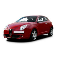
MITO User Manual
338 pages
159 Owner’s Handbook Manual
289 pages
GIULIETTA Owner’s Handbook Manual
250 pages
MiTo Owner’s Manual
271 pages
Brera Owner’s Manual
212 pages
Giulietta Owner’s Handbook Manual
271 pages
GT Owner’s Manual

316 pages
STELVIO 2020 Owner’s Manual
338 pages
ALFA 159 2010 Owner’s Handbook Manual

302 pages
159 Owner’s Manual
212 pages
Giulia 2019 User Manual
280 pages
166 Booklet

284 pages
Giulia 2020 Owner’s Manual
46 pages
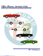
1966 to 1994 Spider Faq
296 pages
Tonale Owner’s Handbook Manual
Models
Document Type
1
147

Owner’s Manual
156
Owner’s Manual
156 GTA
Owner’s Manual • Manual
159
Owner’s Handbook Manual • Owner’s Manual • Owner’s Manual • Training Material • User Manual
164
Service Manual
166
Booklet
1750 Berlina
Owner’s Manual • Shop Manual • Instruction Book
1750 GT Veloce
Owner’s Manual
1750 Spider Veloce
Owner’s Manual
1966 Spider 105
Faq
1966 Spider 115
Faq
1966 to 1994 Spider
Faq
1967 Spider 105
Faq
1967 Spider 115
Faq
1968 Spider 105
Faq
1968 Spider 115
Faq
1969 Spider 105
Faq
1969 Spider 115
Faq
1970 Spider 105
Faq
1970 Spider 115
Faq
1971 Spider 105
Faq
1971 Spider 115
Faq
1972 Spider 105
Faq
1972 Spider 115
Faq
1973 Spider 105
Faq
1973 Spider 115
Faq
1974 Spider 105
Faq
1974 Spider 115
Faq
1975 Spider 105
Faq
1975 Spider 115
Faq
1976 Spider 105
Faq
1976 Spider 115
Faq
1977 Spider 105
Faq
1977 Spider 115
Faq
1978 Spider 105
Faq
1978 Spider 115
Faq
1979 Spider 105
Faq
1979 Spider 115
Faq
1980 Spider 105
Faq
1980 Spider 115
Faq
1981 Spider 105
Faq
1981 Spider 115
Faq
1982 Spider 105
Faq
1982 Spider 115
Faq
1983 Spider 105
Faq
1983 Spider 115
Faq
1984 Spider 105
Faq
1984 Spider 115
Faq
1985 Spider 105
Faq
1985 Spider 115
Faq
1986 Spider 105
Faq
1986 Spider 115
Faq
1987 Spider 105
Faq
1987 Spider 115
Faq
1988 Spider 105
Faq
1988 Spider 115
Faq
1989 Spider 105
Faq
1989 Spider 115
Faq
1990 Spider 105
Faq
1990 Spider 115
Faq
1991 164
Service Manual
1991 Spider 105
Faq
1991 Spider 115
Faq
1992 164
Service Manual
1992 Spider 105
Faq
1992 Spider 115
Faq
1993 164
Service Manual
1993 Spider 105
Faq
1993 Spider 115
Faq
1994 Spider 105
Faq
1994 Spider 115
Faq
2
2000 Spider Veloce 1979
Owner’s Manual
3
33
Workshop Manual • Workshop Manual
33 1.3S Sport Wagon
Workshop Manual Supplement
33 1.8TD Sport Wagon
Workshop Manual Supplement
33 6.7S Sport Wagon
Workshop Manual Supplement
33 a.5 4×4 Sport Wagon
Workshop Manual Supplement
33 Sport Wagon Series
Workshop Manual Supplement
4
4C 2016
User Manual • Owner’s Manual • Owner’s Manual
4C 2017
Owner’s Manual • User Manual
4C Spider
Owner’s Manual • User Manual • User Manual • Manual
4C Spider 2015
User Manual • User Manual • Owner’s Supplement • Owner’s Manual • Owner’s Manual • Owner’s Manual • User Manual • Owner’s Handbook Manual • Service Handbook • Owner’s Handbook Manual
4C Spider 2020
Owner’s Manual • Owner’s Manual
7
75 2.5 V6
Owner’s Manual
75 3.0 V6
Owner’s Manual
75 T.Spark
Owner’s Manual
8
8C Spider
Owner’s Manual
A
Alfa 147
Owner’s Manual • Quick Start Manual
Alfa 147 GTA
Owner’s Manual
Alfa 156
Owner’s Manual • Manual
ALFA 159 2010
Owner’s Handbook Manual
Alfa GT
Owner’s Manual
Alfetta
Workshop Manual
B
Brera
Owner’s Manual • User Manual • User Manual
G
GIULIA
Shop Manual • Owner’s Handbook Manual • Owner’s Handbook Manual • Owner’s Handbook Manual • Owner’s Handbook Manual • Owner’s Handbook Manual • Owner’s Handbook Manual • Quick Manual
giulia 1600 T1
Shop Manual
Giulia 2017
User Manual • Owner’s Manual • Manual • Quick Manual
Giulia 2018
Manual
Giulia 2019
User Manual
Giulia 2020
Owner’s Manual • Manual
GIULIA 2021
Owner’s Manual
GIULIA 2022
Owner’s Manual
Giulia 952 2017
Owner’s Handbook Manual
Giulia 952 D-SEDAN 2016
Owner’s Handbook Manual
Giulia GTA
Owner’s Handbook Manual
Giulia GTAm
Owner’s Handbook Manual
Giulia Quadrifoglio 2017
Owner’s Manual
Giulia-GTA
Owner’s Handbook Manual
Giulia-GTAm
Owner’s Handbook Manual
GIULIETTA
Owner’s Handbook Manual • User Manual • Owner’s Handbook Manual • Owner’s Handbook Manual
Giulietta 2.0 JTDM
Manual
GT
Owner’s Manual
M
MITO
Owner’s Manual • User Manual
MiTo 2013
Owner’s Handbook Manual
MiTo 2015
Owner’s Handbook Manual
MiTo 2016
Owner’s Handbook Manual
S
Spider 2008
Owner’s Manual
Spider-Gtv
Repair Instructions
Stelvio
User Manual • Owner’s Handbook Manual • Quick Manual • Supplement To Owners Handbook • Owner’s Handbook Manual • Quick Start Manual • Manual
STELVIO 2018
User Manual • Owner’s Manual • Owner’s Manual
Stelvio 2019
User Manual
STELVIO 2020
Owner’s Manual • Manual
STELVIO 2021
Owner’s Manual • Quick Manual
STELVIO 2022
Owner’s Handbook Manual
STELVIO 949
Owner’s Handbook Manual
Stelvio Veloce Ti 2022
Manual
T
Tonale
Owner’s Handbook Manual
145,73 Мб
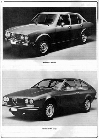
Руководство по ремонту и эксплуатации Alfa Romeo Alfetta /
Формат: pdf
-
Год:
1991
-
Страниц:
277
-
Язык:
английский
-
Размер:
145,73 Мб
-
Категории:
В руководстве по ремонту и эксплуатации Alfa Romeo Alfetta / GTV (1973-1987 г. выпуска), автовладельцы смогут узнать все о моделях автомобилей своей любимой марки.
32,92 Мб
Руководство по ремонту и эксплуатации Alfa Romeo 156
Формат: pdf
-
Год:
2009
-
Страниц:
274
-
Язык:
русский
-
Размер:
32,92 Мб
-
Категории:
В данном руководстве с максимальными деталями описано все, что связано с автомобилем Alfa Romeo 156. Здесь вы сможете найти рекомендации по эксплуатации автомобиля и конечно всевозможные его поломки, вместе с вариантами их решения.
53,9 Мб
Руководство по ремонту и техническому обслуживанию Alfa
Формат: pdf
-
Год:
1983
-
Страниц:
2576
-
Язык:
английский
-
Размер:
53,9 Мб
-
Категории:
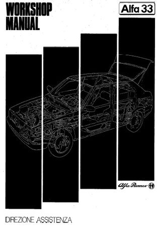
Данное руководство предназначено для владельцев автомобилей марки Alfa Romeo 33. Оно позволит владельцу самостоятельно и максимально быстро спланировать ремонт автомобиля.
16,7 Мб
Руководство по ремонту Alfa Romeo 33
Формат: pdf
-
Год:
1983
-
Страниц:
378+210
-
Язык:
английский
-
Размер:
16,7 Мб
-
Категории:
Руководство по ремонту Alfa Romeo 33 будет интересно всем владельцам этой модели. Вы сможете изучить инструкцию по данному автомобилю со всеми характеристиками и рекомендациями по эксплуатации.
603,93 Мб
Alfa Romeo: Все автомобили начиная с 1910 года
Формат: pdf
-
Год:
1978
-
Страниц:
901
-
Язык:
итальянский, английский
-
Размер:
603,93 Мб
-
Категории:
Книга «Alfa Romeo: Все автомобили начиная с 1910 года» понравится всем любителям данной марки машин. В ней подробно рассмотрены разные автомобили производившиеся заводом с 1910 года.
10,6 Мб
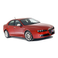
Руководство по эксплуатации Alfa Romeo 159
Формат: pdf
-
Год:
2008
-
Страниц:
331
-
Язык:
русский
-
Размер:
10,6 Мб
-
Категории:
Руководство по эксплуатации Alfa Romeo 159 будет полезно владельцам данного автомобиля, так как информация в нем представлена очень понятно и подробно. Данное пособие может пригодиться в дороге.
64,4 Мб
Руководство по ремонту Alfa Romeo 75 (с 1987 г. выпуска)
Формат: pdf
-
Год:
2005
-
Страниц:
141
-
Язык:
русский
-
Размер:
64,4 Мб
-
Категории:
Данное руководство для модели Alfa Romeo 75, составлено на основании работы и опыта сотрудников станций техобслуживания, с детальным описанием всех процедур ремонта и обслуживания автомобиля.

69,4 Мб
Руководство по ремонту и техническому обслуживанию Alfa
Формат: pdf
-
Год:
1997
-
Страниц:
158
-
Язык:
русский
-
Размер:
69,4 Мб
-
Категории:
Руководство для авто Alfa Romeo 164 станет любимым пособием для изучения своего автомобиля. В нем представлено огромное количество информации по обслуживанию и ремонту отдельных агрегатов и машины в целом.
- Manuals
- Brands
- Alfa Romeo Manuals
- Automobile
- STELVIO 2021
- Owner’s manual
-
Contents
-
Table of Contents
-
Bookmarks
Quick Links
www.inhauto.com
2 0 2 1 O W N E R ‘ S M A N U A L
Related Manuals for Alfa Romeo STELVIO 2021
Summary of Contents for Alfa Romeo STELVIO 2021
-
Page 1
www.inhauto.com 2 0 2 1 O W N E R ’ S M A N U A L… -
Page 2
This Owner’s Manual illustrates and describes the operation of features and equipment that are either standard or optional on this vehicle. This manual may also include a description of features and equipment that are no longer available or were not ordered on this vehicle. Please disregard any features and equipment described in this manual that are not on this vehicle. -
Page 3
Alfa Romeo offers to its customers, the vehicle’s warranty coverage, and the details of the terms and conditions for maintaining its validity. We are sure that these will help you to get in touch with and appreciate both your new vehicle and the service provided by the people at Alfa Romeo. -
Page 4: Refueling
Refueling Gas engines: Do not use fuel containing methanol or ethanol E85. Using these mixtures may cause misfiring and driving issues, as well as damage vital components of the supply system. Diesel engines: Do not use other products or mixtures as they may cause damage to the engine beyond repair and consequently invali- date the warranty.
-
Page 5: Rollover Warning
Rollover Warning Utility vehicles have a significantly higher rollover rate than other types of vehicles. This vehicle has a higher ground clearance and a higher center of gravity than many passenger vehicles. It is capable of performing better in a wide variety of off-road applications. Driven in an unsafe manner, all vehicles can go out of control.
-
Page 6: Accessories Purchased By The Owner
Accessories Purchased By The Owner WARNING! Any change or alteration of the vehicle might seriously affect its safety and road handling, thus causing accidents, in which the occupants could even be fatally injured. If you decide to install electrical accessories that require a permanent electrical supply (e.g. radio, satellite anti-theft system, etc.) or accessories that in any case drain the electrical supply after purchasing the vehicle, contact an authorized dealer.
-
Page 7: Radio Transmitters And Mobile Phones
Radio Transmitters And Mobile Phones Radio transmitter equipment (vehicle mobile phones, CB radios, amateur radio etc.) cannot be used inside the vehicle unless a separate antenna is mounted externally. Transmission and reception of these devices may be affected by the shielding effect of the vehicle body. As far as the use of approved mobile phones is concerned, follow the usage instructions provided by the mobile phone manufacturer.
-
Page 8
WARNING! These statements are against operating procedures that could result in a collision, bodily injury and/or death. CAUTION! These statements are against procedures that could result in damage to your vehicle. NOTE: A suggestion which will improve installation, operation, and reliability. If not followed, may result in damage. TIP: General ideas/solutions/suggestions on easier use of the product or functionality. -
Page 9: Getting To Know Your Vehicle
GETTING TO KNOW YOUR VEHICLE GETTING TO KNOW YOUR INSTRUMENT PANEL STARTING AND OPERATING SAFETY IN CASE OF EMERGENCY SERVICING AND MAINTENANCE www.inhauto.com TECHNICAL SPECIFICATIONS CUSTOMER ASSISTANCE INDEX…
-
Page 10: Table Of Contents
DEAR CUSTOMER VEHICLE SECURITY SYSTEM — MIRRORS ……….37 IF EQUIPPED……….23 Automatic Dimming Mirror ….37 READ THIS CAREFULLY Vanity Mirror ………..37 To Arm The System…….. 23 To Disarm The System ……23 Outside Power Mirrors ……38 Refueling…………. 2 Power Folding Outside Mirrors….38 Volumetric/Anti-Lift Protection —…
-
Page 11
Automatic High Beam Headlights — POWER WINDOWS ……..58 INSTRUMENT CLUSTER DISPLAY ….69 If Equipped ……….43 Power Window Controls ……58 Instrument Cluster Display Parking Lights ……..44 Auto-Up Feature With Anti-Pinch Description ……….69 Headlight Off Delay…….. 44 Protection……….59 Reconfigurable Instrument Cluster Rear Fog Lights …….. -
Page 12
STARTING AND OPERATING STOP/START SYSTEM……101 Indications On The Display ….118 System Status ……..119 Operating Mode……..101 STARTING THE ENGINE……86 Limited System Availability/ System Manual Activation/ Starting Procedure……… 86 Operation ……….119 Deactivation……… 102 Remote Starting System ……. 86 TRAFFIC SIGN RECOGNITION (TSR) Possible Reasons The Engine Does Cold Weather Operation…… -
Page 13
LANE KEEPING ASSIST (LKA) SAFETY OCCUPANT RESTRAINT SYSTEMS..163 SYSTEM —IF EQUIPPED……128 Occupant Restraint Systems ACTIVE SAFETY SYSTEMS……145 Features ……….163 Turning Lane Keeping Assist On Or Anti-Lock Brake System (ABS) … 145 Off …………129 Important Safety Precautions …. 163 Active Torque Vectoring (ATV) Seat Belt Systems …… -
Page 14
JUMP STARTING ……..201 BATTERY RECHARGING ……218 BODYWORK ……….. 249 Remote Battery Connection Posts..202 Important Notes ……..218 Protection Against Atmospheric Jump Starting Procedure…..203 VEHICLE MAINTENANCE……219 Agents ……….249 Bump Starting ……..204 Engine Oil ……….219 Corrosion Warranty ……250 ENGINE OVERHEATING …… -
Page 15
Be Reasonable With Requests… 266 Materials Added To Fuel ….261 General Information……268 IF YOU NEED ASSISTANCE ….266 Fuel System Cautions……261 Alfa Romeo Customer Center ….. 266 FLUID CAPACITIES ……… 262 Alfa Romeo Customer Care ENGINE FLUIDS AND LUBRICANTS ..263 (Canada)……….266 CHASSIS FLUIDS AND LUBRICANTS.. -
Page 16
Some car components have colored labels Amber Warning Lights Amber Warning Lights with symbols indicating precautions to be observed when using this component. It is Anti-Lock Brake Engine Check/ important to follow all warnings when oper- System (ABS) Malfunction ating your vehicle. See below for the definition Warning Light Indicator Light (MIL) of each symbol Ú… -
Page 17
Blue Warning Lights Red Symbols Amber Symbols High Beam Indicator Engine Coolant Engine Oil Change Light — If Equipped Temperature Too Required— If Ú page 78 High Equipped Ú page 79 Ú page 80 Red Symbols Hood Cap Not Engine Oil Pressure Properly Shut Sensor Failure Alfa Steering Torque… -
Page 18
Amber Symbols Amber Symbols Amber Symbols Fuel Level Sensor Speed Limiter All Wheel Drive Failure System Failure Failure Ú page 81 Ú page 82 Ú page 83 Exterior Lights Temporary All Wheel Loose Fuel Filler Cap Failure Drive Failure — If Ú… -
Page 19
Amber Symbols Green Symbols Blue Indicator Lights Automatic High Driver Attention Headlights Assist (DAA) System Beam Headlights — Ú page 84 If Equipped Failure Ú page 84 Ú page 83 Automatic Headlights High Beam Highway Assist Ú page 84 Headlights System (HAS)/ Traffic Jam Assist Ú… -
Page 20: Keys
In this section, you will find important informa- When the doors are locked/unlocked, the turn tion to help you become familiar with the signals will flash and the illuminated entry features needed to operate your vehicle, and system will be activated. how they function.
-
Page 21
Perchlorate Material — special handling 2. Remove the emergency key from its 4. Remove the battery from its slot and may apply. See www.dtsc.ca.gov/hazard- housing. replace it with a new one. When replacing ouswaste/perchlorate for further informa- the battery, match the (+) sign on the tion. -
Page 22: Engine Immobilizer System
Programming And Requesting Additional NOTE: If the vehicle security light turns on during Key Fobs normal vehicle operation (vehicle running for When having the Engine Immobilizer longer than 10 seconds), it indicates that Programming the key fob may be performed by system serviced, bring all vehicle keys with there is a fault in the electronics.
-
Page 23
tion, a back up method can be used to operate addition to the chime, the message will the ignition switch. Proceed as follows: display “Ignition Or Accessory On” in the cluster Ú page 268. 1. Lift the front armrest. WARNING! 2. -
Page 24: Remote Start — If Equipped
will lock, the turn signals will flash twice, and Battery at an acceptable charge level CAUTION! the horn will chirp twice. Pushing the Remote PANIC button not pushed Start button a third time shuts the engine off. An unlocked vehicle is an invitation for System not disabled from previous remote thieves.
-
Page 25: Remote Start Comfort Systems — If Equipped
Remote Start Comfort Systems — If The horn will pulse To Disarm The System Equipped The turn signals will flash The Vehicle Security system can be disarmed using any of the following methods: When Remote Start is activated, the heated The vehicle security light in the instrument …
-
Page 26: Volumetric/Anti-Lift Protection — If Equipped
battery is reconnected; the exterior lights will Any disabling of the Volumetric/Anti-Lift WARNING! (Continued) flash, and the horn will sound. If this occurs, Protection must be repeated each time the disarm the Vehicle Security system. ignition is placed in the OFF position. For personal security and safety in the …
-
Page 27: Locking The Doors With A Depleted Battery
Locking The Doors With A Depleted Battery Unlock the driver’s door lock with the emer- block the key fob’s wireless signal and gency key prevent the Passive Entry system from Proceed as follows to lock the doors if the locking/unlocking the vehicle.
-
Page 28
NOTE: with an automatic door unlock feature which will function if the ignition switch is in the OFF If “Unlock All Doors 1st Press” is position. programmed all doors will unlock when you The vehicle will not unlock the doors if an grab hold of the front driver’s door handle. -
Page 29: Power Lock Safety Device
The turn signals will flash to let you know that the power lock is active. If one or more of the doors are not closed correctly, the Power Lock Safety Device will not activate, preventing a person from getting stuck inside the passenger compartment by entering the vehicle, and then closing the open door.
-
Page 30: Steering Wheel
To use the system, open each rear door, use a (unlocked position), roll down the window, flat blade screwdriver (or emergency key) and and open the door with the outside door rotate the dial to the lock or unlock position. handle.
-
Page 31: Heated Steering Wheel — If Equipped
WARNING! WARNING! Do not adjust the steering column while It is absolutely forbidden to carry out any driving. Adjusting the steering column after-market operation involving steering while driving or driving with the steering system or steering column modifications column unlocked, could cause the driver (e.g.
-
Page 32: Driver Memory Settings — If Equipped
DRIVER MEMORY SETTINGS — IF 1. Place the vehicle’s ignition in the ACC posi- WARNING! tion (do not start the engine), and make EQUIPPED sure the driver’s door is closed. It is dangerous to ride in a cargo area, This feature allows the driver to store up to inside or outside of a vehicle.
-
Page 33: Split Folding Rear Seat
Adjusting The Seat Forward Or Rearward WARNING! (Continued) The adjustment lever is at the front of the seat, Do not ride with the seatback reclined so near the floor. Pull the bar upward to move the that the shoulder belt is no longer resting seat forward or rearward.
-
Page 34
Central Backrest Section Repositioning Proceed as follows: NOTE: Using the head restraint, lift the central portion 1. Completely lower the rear seat head Pull both seat back release levers to fold upwards, manually guiding it back into place. restraints Ú page 35. down both backrests. -
Page 35: Power Adjustment (Front Seats)
Power Adjustment (Front Seats) Adjusting The Seat Forward Or Rearward WARNING! The seat can be adjusted both forward and NOTE: Adjusting a seat while driving may be rearward by using the seat adjustment switch. The seat layout may vary according to the dangerous.
-
Page 36: Heated Seats — If Equipped
Seat Cushion Extension — If Equipped The function is associated with power driver Front Heated Seats — If Equipped seats for each of the three stored positions. NOTE: Lift the adjustment lever and push the front of Quadrifoglio vehicles equipped with Sparco The Easy Entry function can be activated/ the cushion forward or rearward to extend the Racing Seats will not be equipped with the…
-
Page 37: Head Restraints
NOTE: NOTE: Front Head Restraints To preserve the battery charge, this function After selecting a heating level, heat will be WARNING! cannot be activated when the engine is off. felt within a few minutes. Head Restraints All occupants, including the driver, should …
-
Page 38
To lower the head restraint, push in the adjust- Rear Head Restraint Adjustments ment button and lower the head restraint to WARNING! the desired height while holding the button. Then, release the adjustment button. All occupants, including the driver, should … -
Page 39: Mirrors
MIRRORS 3. Push the adjustment button and the Vanity Mirror release button at the side of the two On the driver and passenger sun visor, there is supports at the same time. Automatic Dimming Mirror a light which illuminates the sun visor mirror 4.
-
Page 40: Outside Power Mirrors
There are courtesy mirrors with lights on the The power mirrors can be adjusted with the Power Folding Outside Mirrors back of the sun visors. ignition in the ACC or ON/RUN position. To fold the door mirrors in using the Power Folding Mirror function, make sure the power mirror control knob is in the neutral position, and move the knob to the power folding posi-…
-
Page 41: Outside Automatic Dimming Mirrors — If Equipped
UNIVERSAL GARAGE DOOR If the door mirrors were folded using the power devices they are programmed to with each mirror control knob, they can only be returned press of the corresponding HomeLink® OPENER (HOMELINK®) to the driving position by moving the knob to button.
-
Page 42: Identifying Whether You Have A Rolling Code Or Non-Rolling Code Device
NOTE: Programming HomeLink® To A Garage Rolling Code Garage Door Opener Final Steps Erasing all channels should only be performed Door Opener NOTE: when programming HomeLink® for the first You have 30 seconds in which to initiate rolling To program any of the HomeLink® buttons to time.
-
Page 43: Programming Homelink® To A Miscellaneous Device
2. Push the programmed HomeLink® button signal during programming. Similar to this Canadian radio frequency laws require trans- to confirm that the garage door opener Canadian law, some U.S. gate operators are mitter signals to time-out (or quit) after several motor operates.
-
Page 44: Exterior Lights
NOTE: wheel. The headlight switch controls the oper- turned on. To turn off the headlights, rotate ation of the headlights, parking lights, instru- the headlight switch back to the O (off) posi- If the indicator light stays on constantly, ment panel lights, instrument panel light tion.
-
Page 45: High Beam Headlights
High Beam Headlights To turn the automatic headlights off, turn the If the high beam headlights are operated headlight switch out of the (AUTO) position. quickly again (pushing the multifunction lever Push the multifunction lever towards the towards the instrument panel), the warning Flash-To-Pass instrument panel to switch the headlights to light/icon…
-
Page 46: Parking Lights
Parking Lights Rear Fog Lights Turn Signals To turn on the parking lights and instrument The rear fog light switch is located within the Move the multifunction lever up or down to panel lights, rotate the headlight switch clock- headlight switch. activate the turn signals.
-
Page 47: Front Map Reading Lights
Front Map Reading Lights NOTE: When doors are locked (either with key fob Before exiting the vehicle, ensure that the or with key inserted on driver side door), the The front map/reading and overhead lights overhead lights are off. This will prevent the overhead light turns off.
-
Page 48: Rear Overhead Light
Rear Overhead Light Instrument Panel Dimmer Control CAUTION! The rear overhead lights are activated or deac- With the daytime running lights or headlights Turn the windshield wipers off when on, rotate the dimmer control upward to tivated by on/off switches located on the front driving through an automatic car wash.
-
Page 49: Rain Sensing Wipers
The windshield wiper stops working three strokes after the stalk is released, followed by a final stroke six seconds later to complete the cycle. Mist Push the lever upward to the MIST position and release for a single wiping cycle. NOTE: The Mist feature does not activate the washer Windshield Wiper Stalk…
-
Page 50: Rear Window Wiper/Washer
If the windshield washer is used with the rain The rain sensor is able to recognize and auto- Headlamp Washers — If Equipped sensor activated, the normal washing cycle is matically adjust itself in the presence of the The windshield wiper lever operates the head- performed, and then the rain sensor resumes following conditions: light washers when the ignition is in the ON…
-
Page 51: Automatic Dual-Zone Climate Control System
Automatic Dual-Zone Climate Control System www.inhauto.com Automatic Climate Control System 1 — Driver Temperature Adjustment Knob 9 — Passenger Temperature Adjustment Knob 2 — Driver Side AUTO Button (Automatic Operation) 10 — SYNC Button (Set Temperature Alignment) Driver/Passenger Side 3 — Driver Side Air Distribution Selection Button 11 —…
-
Page 52
www.inhauto.com Automatic Climate Control System (Touchscreen Controls) 1 — Driver Side Temperature Adjustment Bar 8 — Heated Rear Window On/Off Button 2 — Driver Side Air Distribution Buttons 9 — MAX-DEF Activation/Deactivation Button (Rapid Defrosting/Demisting) 3 — Fan Speed Adjustment Button 10 —… -
Page 53
Compressor variations (for cooling/dehu- A/C activation CAUTION! midifying the air) Front Defroster The system uses R1234yf refrigerant, Air recirculation Air recirculation which does not pollute the environment in The Climate Control System can also be oper- the event of accidental leakage. -
Page 54
NOTE: At low external temperatures or in high Rear Defrost When the A/C is off, the Climate Control humidity, the automatic function turns off to Push the Rear Defrost button to acti- system can not produce air that is colder than avoid fogging up the windows. -
Page 55
NOTE: AUTO Button Blower Speed The MAX-DEF function remains active for When the AUTO button is pushed (indicator Turn the Blower Speed Knob to increase or approximately three minutes once the engine illuminated), the Climate Control system auto- decrease the blower speed. The speed is coolant reaches the proper temperature. -
Page 56
the flow of air. The air vanes of the center To Turn On The Climate Control System Front Defrost And Panel Mode outlets and outboard outlets can be moved up Air flow is distributed between the To switch the Climate Control system on in and down or side to side to regulate airflow windshield demisting/defrosting… -
Page 57: Interior Storage And Equipment
INTERIOR STORAGE AND Humidity Sensor With Stop/Start system on (engine is OFF), air flow is reduced to keep the compartment EQUIPMENT The Humidity Sensor helps prevent the comfort conditions for longer. windows from fogging up. The AUTO function Until the temperature drastically changes Glove Compartment (indicator illuminated) must be on for the within the cabin, the climate control system…
-
Page 58: Center Console
Rear Armrest Power Outlets WARNING! The rear armrest is foldable and can be stored The Instrument Panel Power Outlet is located Do not operate this vehicle with a glove in the backrest. on the center stack under the climate controls. compartment in the open position.
-
Page 59: Cigar Lighter And Ash Tray — If Equipped
1 — Cigar Lighter If equipped, the ash tray is a removable plastic Luggage Compartment Power Outlet Power Inverter container located inside the cupholder. NOTE: Cigar Lighter And Ash Tray — If Equipped Wireless Charging Pad — If Equipped Do not connect devices with powers higher If equipped, the cigar lighter is located on the than 150 W to the socket.
-
Page 60: Power Windows
Your mobile phone must be designed for Qi The following messages will display in the wireless charging. radio system: “Your phone is being charged” — The phone NOTE: has begun to charge. Do not place the key fob or any other type of …
-
Page 61: Auto-Up Feature With Anti-Pinch Protection
To close the window, pull the window switch reversed and the window lowers by about together to minimize the buffeting. If the up. To stop the window during Auto-Up opera- 8 inches (20 cm) in relation to the first stop buffeting occurs with the sunroof open, adjust tion, push or pull the window switch again.
-
Page 62: Opening And Closing The Sunroof
The sunroof has three preset positions: Opening And Closing The Sunroof Sunshade Operation Fully closed To open the sunroof’s front panel, push the The sunshade is power operated. open/close button toward the rear of the Comfort (intermediate opening) Push the Power Shade open/close button vehicle to open to the comfort position (half toward the rear of the vehicle to open the sun…
-
Page 63: Sunroof Maintenance
Proceed as follows: 7. Confirm express operations for the 2. Lift the hood slightly. Move the underhood sunroof glass and sunshade are functional latch from right to left to release the hood. 1. With the ignition in the ON/RUN position, for opening and closing operations.
-
Page 64: Closing The Hood
Closing The Hood Pushing the external liftgate release switch The turn signal indicators will blink and the (when the liftgate is unlocked) interior lights will turn on when the liftgate is To close, lower the hood to approximately opened. They turn off automatically when the Lifting the interior liftgate release button on 16 inches (40 cm) from the engine compart- …
-
Page 65: Closing
Pull to release the lock. This function can be selected on the radio system. To set the liftgate opening height, refer to the Information and Entertainment System Owner’s Manual Supplement for further information. Hands-Free Liftgate — If Equipped To operate the Hands-Free Liftgate system: 1.
-
Page 66: Liftgate Initialization
If it is closed, the Hands-Free Liftgate unlocks Cargo Area Features WARNING! (Continued) and opens completely, and with another Retractable Cargo Area Cover movement of the foot, it stops. A further move- If you are required to drive with the liftgate …
-
Page 67
3. Pull the two cover hooks (one on each Rear Cargo Anchors side) towards the inside of the cargo area. The cargo area floor may be equipped with Then lift the cover up and remove it. fixed or mobile anchoring loops that allows you to anchor and secure luggage safely. -
Page 68
Grocery Hooks Accessing The Tire Service Kit — If Equipped Two hooks (one on the left side and one on the To access the Tire Service Kit Ú page 198, lift right side) are also available on the side up the load floor by the handle. panels to fix loads that are not excessively heavy (e.g. -
Page 69: Instrument Panel Features
This section gives you all the information you need to understand and use the instrument panel correctly. INSTRUMENT PANEL FEATURES Instrument Cluster www.inhauto.com Instrument Cluster…
-
Page 70: Instrument Cluster Descriptions
www.inhauto.com Quadrifoglio Instrument Cluster Instrument Cluster Descriptions 2. Engine Oil Temperature Gauge WARNING! 1. Tachometer • The digital bar indicator monitors the A hot engine cooling system is dangerous. temperature of the engine oil and starts • Indicates the engine speed in revolu- You or others could be badly burned by supplying indications when the fluid tions per minute (RPM x 1000).
-
Page 71: Instrument Cluster Display
Reconfigurable Instrument Cluster Display CAUTION! During operation, the instrument cluster Driving with a hot engine cooling system display is divided into multiple sections which could damage your vehicle. show driving data, warnings, and failure indi- temperature gauge reads “H” pull over and cations.
-
Page 72
7. Traffic Sign Recognition (TSR) Information Home Display The parameters shown on the display, for the modes: Dynamic, Normal and Ad- 8. Time vanced Efficiency are: 9. External Temperature • Time 10. Main Display: Vehicle Speed Display, Trip • Outside Temperature Computer Information, etc… -
Page 73
Natural The three central icons on the screen indi- cate the effectiveness of the driving style linked to the parameters of: acceleration, deceleration and gearshift with a view to reducing fuel consumption. The graphic bar below the icons shows cur- rent consumption and the green line rep- resents the optimal area. -
Page 74: Customer Programmable Settings
Race (If Equipped) The displayed parameters are related to vehicle stability, the graphs illustrate the The display graphically shows the values trend of the longitudinal/lateral accelera- tions (G-meter information), considering ○ engine torque; gravity acceleration as a reference unit. ○ turbocharger pressure; Lateral acceleration peaks are also indi- ○…
-
Page 75
To access the settings list in the radio, proceed Restore Unit & Language Settings: restores Show Phone Info: allows you to activate/ as follows: the factory settings deactivate repetition of the phone function screens also on the instrument cluster Press the Home button to access the main … -
Page 76: Warning Lights And Messages On The Instrument Panel
To access and the change the setting, turn and Red Warning Lights corrected. If the problem is related to the push the Rotary Pad or press the desired brake booster, the ABS pump will run when Air Bag Warning Light setting on the touchscreen.
-
Page 77: Amber Warning Lights
NOTE: Electronic Brake Force Distribution (EBD) WARNING! (Continued) This light shows only that the parking brake is Failure applied. It does not show the degree of brake If the warning light does not turn on when The simultaneous turning on of the application.
-
Page 78
required. However, the conventional brake Electronic Stability Control (ESC) OFF Should one or more tires be in the condition system will continue to operate normally if the Indicator Light — If Equipped mentioned above, the display will show the brake indicator light is not on. indications corresponding to each tire. -
Page 79
also reduces fuel efficiency and tire tread life, Under these conditions, the vehicle can WARNING! and may affect the vehicle’s handling and continue traveling at moderate speed but stopping ability. without demanding excessive effort from the The TPMS has been optimized for the engine or high speed. -
Page 80: Green Indicator Lights
Headlight Off Delay Contact an authorized dealer to have the WARNING! system checked. This function allows the headlights to remain If the warning light (or the icon on the on for 30, 60 or 90 seconds after the ignition Alternator Failure display) flashes while driving, contact an was placed in the OFF position.
-
Page 81
Door Open Place the gear selector in the Park (P) position the engine off. Check that the coolant level is and the ignition in the off position: the warning correct as described above. The telltale turns on when one or light should switch off. -
Page 82: Amber Symbols
the oil level can be checked on the display Break-In Attempt The telltale will illuminate NOTE: upon entering the vehicle and also by acti- when the ignition is cycled to ON position, to After the first indication, each time the engine vating the “Oil level”…
-
Page 83
Engine Oil Level Sensor Failure Contact an authorized dealer as soon as Keyless System Failure possible. The telltale will illuminate in the The telltale will illuminate in the event of engine oil level sensor event of keyless system failure. Blind Spot Monitoring System Failure — If failure. -
Page 84
Automatic Transmission Fluid Overheating Electric Park Brake Failure Service Adaptive Cruise Control (ACC) System The telltale will illuminate in the case The telltale will illuminate and a of transmission overheating, after a message will display to signal a This light will illuminate when the particularly demanding use. -
Page 85
DAA system failure. suspension system. This telltale will illuminate to indicate Contact an authorized dealer to have the Contact an Alfa Romeo Dealership as soon as that the AWD dynamic control system checked. possible to have the failure eliminated. -
Page 86: Green Symbols
Green Symbols Blue Symbols The aim of the OBD system (Onboard Diag- nostic) is to: Headlights Automatic High Beam Headlights — If Monitor the efficiency of the system Equipped The telltale will illuminate when the Indicate an increase in emissions …
-
Page 87: Emissions Inspection And Maintenance Program
For states that require an Inspection 3. Approximately 15 seconds later, one of WARNING! and Maintenance (I/M), this check two things will happen: verifies the Malfunction Indicator ONLY an authorized service technician • The MIL will flash for about 10 seconds Light (MIL) is functioning and is not should connect equipment to the OBD II and then return to being fully illumi-…
-
Page 88: Starting The Engine
STARTING THE ENGINE Starting Procedure WARNING! (Continued) Before starting the engine, be sure to adjust Proceed as follows: the seat, the interior rear view mirror, door If the vehicle has a discharged battery, mirrors, and fasten the seat belt correctly. 1.
-
Page 89: Cold Weather Operation
How To Use Remote Start Remote Start Windshield Wiper De–Icer Acti- Extended Park Starting vation — If Equipped All of the following conditions must be met If the vehicle has not been started or driven for before the engine will remote start: When remote start is active and the outside ambient at least 30 days, it is advisable to follow the temperature is less than 39°F (4°C), the Windshield…
-
Page 90: After Starting — Warming Up The Engine
After Starting — Warming Up The Engine With the keyless ignition system, it is possible WARNING! to exit the vehicle taking the key fob with you, Proceed as follows: without the engine switching off. The vehicle Never pour fuel or other flammable liquid …
-
Page 91: Engine Block Heater — If Equipped
ENGINE BLOCK HEATER — IF The engine block heater must be plugged in 0 to 100 miles (0 to 160 km): at least one hour to have a warming effect EQUIPPED Do not allow the engine to operate at idle for …
-
Page 92: Electric Park Brake (Epb)
For the first 1,500 miles (2,414 km): NOTE: CAUTION! Normally, the EPB is engaged automatically Do not participate in track events, sport when the engine is stopped. This function can driving schools, or similar activities during With the Electronic Parking Brake failure be deactivated/activated on the Information the first 1,500 miles (2,414 km).
-
Page 93: Electric Park Brake (Epb) Operating Modes
Disengaging The EPB Manually move the vehicle (DRIVE [D] or REVERSE WARNING! (Continued) [R]). This feature can be turned on or off in In order to manually release the parking brake, the Information and Entertainment System. the ignition should be in the ACC mode. Press Be sure the parking brake is fully disen- …
-
Page 94: Automatic Transmission
The EPB engages automatically to prevent WARNING! WARNING! (Continued) vehicle movement if: The vehicle speed is below 2 mph (3 km/h). It is dangerous to shift out of PARK or Never leave children alone in a vehicle, or …
-
Page 95: Display
Display D = DRIVE (automatic forward speed) AutoStick: + manually shift to higher gear; – The following information is shown on the manually shift to lower gear dedicated area of the display: In Automatic Mode: the active mode (P, R, …
-
Page 96: Transmission Operating Modes
To transition the vehicle into REVERSE (R) NOTE: WARNING! (Continued) mode from DRIVE (D) mode, or into DRIVE (D) Never try to engage PARK (P) mode when the mode from REVERSE (R) mode, it is necessary vehicle is moving. Before leaving the vehicle, It is dangerous to shift out of PARK or …
-
Page 97
NEUTRAL (N) AutoStick WARNING! (Continued) Use this range when the vehicle is standing for In the case of frequent shifting (e.g. for sport Never leave children alone in a vehicle, or prolonged periods with the engine running. driving, when the vehicle is driven with a heavy … -
Page 98: Automatic Transmission Limp Home Mode
an operating mode in which the vehicle can 3. Push and hold the ignition until the engine slow down easily. turns off. The vehicle will keep the gear selected by 4. Wait for about 10 seconds, then restart the driver until the safety conditions allow it. the engine.
-
Page 99: Important Notes
Brake Transmission Shift Interlock Disabling Do not change between PARK (P), REVERSE WARNING! (Continued) (R), NEUTRAL (N) or DRIVE (D) modes with Only if strictly necessary (e.g. pushing the engine running at a speed above idling. vehicle, conveyor vehicle washing systems), Unintended movement of a vehicle could …
-
Page 100: Alfa Dna Selector
On the instrument cluster display, the different CAUTION! modes are characterized by different colors: Only engage the gear with engine at idling Natural — Blue while fully pressing the brake pedal. If the Dynamic — Red transmission temperature exceeds the normal operating limits, the transmission Advanced Efficiency — Green …
-
Page 101
Activation «Dynamic» Mode It is activated by rotating the selector to the Activation letter «n»; the display will light up in blue. It is activated by rotating the selector to the letter «d»; the display will light up in red. Dynamic Mode Performance Display The «Performance»… -
Page 102
ESC and ASR systems: intervention thresholds “RACE” Mode The screen displays the lateral and longitu- aimed at ensuring maximum safety in low-grip dinal acceleration peaks. Activation driving conditions. It is advisable to select “RACE” Mode is activated by rotating the “Advanced Efficiency”… -
Page 103: Alfa Active Suspension (Aas) — If Equipped
«Natural» mode, depending on which mode Operating Mode was selected before the engine was Stopping The Engine stopped. With the vehicle at a standstill and brake pedal When the engine is started again, the pressed, the engine switches off if the gear selector «RACE»…
-
Page 104: System Manual Activation/Deactivation
System Manual Activation/Deactivation Possible Reasons The Engine Does Not Vehicle moving (e.g. when driving on roads Autostop with a grade). To manually activate/deactivate the system, Engine stopping by the Stop/Start system push the button located on the control panel …
-
Page 105: Irregular Operation
Irregular Operation NOTE: Activating The Device After setting the ignition to OFF and having To access this feature, select the “Driver Assis- In the event of malfunction, the Stop/Start closed the driver side door, wait at least one tance” widget in the radio system, then select system is deactivated.
-
Page 106: Exceeding The Programmed Speed
To access the function on the main menu, Deactivation select the following items in order: The feature can be activated/deactivated 1. “Driver Assistance” through the radio system. Deactivating The Device 2. “Speed Limiter — Set Speed” To access this feature, select the “Driver Assis- By turning the Rotary Pad, the speed increases tance”…
-
Page 107
To Activate To Set A Desired Speed To Vary The Speed Setting To activate the Cruise Control System, push To set a desired speed, proceed as follows: To Increase Or Decrease The Set Speed the on/off button located on the left side of the When the Cruise Control is set, you can 1. -
Page 108: Adaptive Cruise Control (Acc) — If Equipped
To Accelerate For Passing NOTE: The set speed is deleted in the following Before returning to the previously set speed, cases: Press the accelerator as you would normally. you must accelerate to a speed close to the Pushing the on/off button a second time …
-
Page 109
NOTE: WARNING! (Continued) Adaptive Cruise Control performance is not guaranteed under the following circum- The ACC system: stances, and it is recommended to turn the • May react to pedestrians, oncoming system off when: vehicles, and stationary objects (e.g., Driving in fog, heavy rain, or snow. -
Page 110
When the ESC system is off. To Activate WARNING! (Continued) To enable the system, push and release the When the Forward Collision Warning system on/off button located on the left side on the When entering a turn lane or highway off … -
Page 111
While the accelerator pedal is pressed, the switch will adjust the speed in 10 km/h WARNING! system will not be able to control the distance increments. between the vehicle and the one ahead. In this Leaving the Adaptive Cruise Control (ACC) By keeping the accelerator pedal pressed, … -
Page 112
to two seconds (for the maximum distance ically adjusts the vehicle’s speed to keep the WARNING! four-bar setting). set distance, independently of the set speed. The Resume function should only be used if The set distance is shown on the display by a The vehicle holds the set distance until: traffic and road conditions permit. -
Page 113
moving within two seconds of your vehicle Limited Operation Warning WARNING! (Continued) coming to a standstill, your vehicle will resume If the dedicated message is shown on the motion without the need for any driver action. The driver is fully responsible for holding a … -
Page 114
ahead. The offset vehicle may move in and out Using ACC On Hills of the line of travel, which can cause your When driving on hills, ACC may not detect a vehicle to brake or accelerate unexpectedly. vehicle in your lane. Depending on the speed, vehicle load, traffic conditions, and the steep- Turns And Bends ness of the hills, ACC performance may be… -
Page 115
IFETEL: RCPBOMR 14-0766 Toutes modifications apportées à cet équipe- Stationary Objects And Vehicles ment qui ne sont pas expressément homo- The ACC system can detect stationary vehicles La operación de este equipo está sujeta a las loguées par Robert BOSCH GmbH peuvent when the vehicle is traveling at speeds siguientes dos condiciones: annuler l’autorisation de la FCC de faire… -
Page 116: Highway Assist System (Has) — If Equipped
Déclaration d’exposition aux radiations If the left or right turn signal is activated Cet équipement est conforme aux limites If the driver intentionally changes lanes d’exposition aux rayonnements IC établies without using the turn signal pour un environnement non contrôlé. Cet équi- If the driver’s seat belt is released pement doit être installé…
-
Page 117: Indications On The Display
If the system detects that the driver’s hands The road lane width must be between 8.5 ft An acoustic signal will also sound. After a have been removed from the steering wheel, and 13.7 ft (2.6 m and 4.2 m) period of time, the HAS system will disable if the system will alert the driver to place their the driver’s hands do not return to the steering…
-
Page 118: Limited System Availability/Operation
ment cluster display warning the driver to Active System (Hands Removed From The Limited System Availability/Operation return their hands to the steering wheel. Steering Wheel For A Long Time) System Availability Active System (Hands Removed From The If the driver still has not returned their hands External factors and conditions may affect the Steering Wheel For A Short Time) to the steering wheel after the screen above is…
-
Page 119: Traffic Jam Assist (Tja) System — If Equipped
Either the camera or radar are damaged, To deactivate the system, push the button WARNING! (Continued) covered, or obstructed (e.g. by mud, ice, again. snow, etc.) Maintain a safe distance from other vehi- cles and pay attention to traffic condi- When driving on hills or roads with narrow …
-
Page 120: Operation
Automatic Deactivation When the automatic suspension conditions The vehicle must be traveling at a speed are over, the TJA system will be automatically between 0 and 37 mph (0 and 60 km/h) System operation will be temporarily disabled reactivated. under the following conditions: The camera, radar, and radio system must …
-
Page 121: System Status
System Status If the driver does not return their hands to the An acoustic signal will sound until the driver steering wheel within a few seconds, the regains control of the vehicle (hands on Active System following screen will appear in the instrument steering wheel).
-
Page 122: Traffic Sign Recognition (Tsr) System — If Equipped
TRAFFIC SIGN RECOGNITION If the camera or sensor is damaged, NOTE: covered, or obstructed (e.g. by mud, ice, (TSR) SYSTEM — IF EQUIPPED If damage to the windshield occurs, have snow, etc.) the windshield replaced by an authorized The Traffic Sign Recognition (TSR) system The bumper is damaged or misaligned dealer as soon as possible.
-
Page 123: Indications On The Display
NOTE: After a predetermined distance, the previ- CAUTION! (Continued) ously displayed road sign changes color to By selecting “Blinking”, the driver can acti- inform the driver that the speed limit The system may have limited operation or vate a warning to display when the speed provided may no longer be valid.
-
Page 124: To Activate/Deactivate
If the speed limit is exceeded according to the To Deactivate When these systems are active, a telltale will road signs or traffic conditions, a dedicated display in the instrument cluster display indi- The system is deactivated under the following graphic message is displayed on the instru- cating the suggested speed provided by the conditions:…
-
Page 125: Parksense Front/Rear Park Assist System — If Equipped
automatically applied and released when CAUTION! performing a reverse parking maneuver if the system detects a possible collision with an The ParkSense system is only a parking obstacle. aid and it is unable to recognize every When the REVERSE gear is engaged and the obstacle, including small…
-
Page 126: Parksense Display
3. “ParkSense” Acoustic Signal In the presence of an obstacle at the front or 4. “Mode” the rear of the vehicle, an acoustic signal with 5. “Sound and Display” variable frequency will sound: The acoustic signal increases in frequency Visual Indications …
-
Page 127: Parksense Warning Display
Pushing the button a second time will turn the NOTE: electrical connector is plugged into the system back on, and the indicator light will When the ignition is placed in the ON/RUN vehicle. The sensors are automatically reacti- turn off. position, the ParkSense system keeps the last vated when the electrical connector is state when the engine was stopped (activated…
-
Page 128: Parksense System Usage Precautions
ParkSense System Usage Precautions remove or close the trailer hitch assembly CAUTION! (Continued) when the vehicle is not being used for NOTE: towing. Do not tamper with nor operate on the Some conditions may influence the perfor- camera. Do not close the openings in the LANE DEPARTURE WARNING mance of the ParkSense system: aesthetic cover located under the interior…
-
Page 129: Turning Lane Departure Warning On Or Off
Turning Lane Departure Warning On Or Off The lane markings are visible at least on Left Lane Departure — Only Left Lane one side. Detected The system is activated/deactivated by When the system is active and only, for There are suitable visibility conditions. pushing the button located on the end of the …
-
Page 130: Changing Lane Departure Warning Status
The system operates in the same way, but Although the vehicle can still be driven in of the vehicle within such markings, in order to mirrored, in the event of exiting the right lane normal conditions, the system may not func- make sure that the vehicle remains inside the when only the right lane marking has been tion properly.
-
Page 131: Turning Lane Keeping Assist On Or Off
Turning Lane Keeping Assist On Or Off A suitable distance is kept from the vehicle Left Lane Departure — Only Left Lane Detected in front When the system is active and only, for The system is activated/deactivated by pressing the button at the end of the multifunction lever.
-
Page 132
NOTE: Hands Presence On The Steering Wheel The system operates in the same way, but Detection mirrored, in the event of exiting the right lane The system is able to detect the presence of when only the right lane marking has been the driver’s hands on the steering wheel. -
Page 133
Changing The System Strength CAUTION! CAUTION! (Continued) The system’s strength can be set through the radio system in the “Driver Assistance” menu. Projecting loads on the roof of the vehicle The camera may have limited or absent Select “Lane Keep Assist — Settings” and then may interfere with the correct operation of operation due to weather conditions such “Strength”. -
Page 134: Rear Back Up Camera / Dynamic Gridlines
REAR BACK UP CAMERA / Selecting “Camera Delay” will allow the colored zones indicate the distance to the rear camera view to remain on the display shortly of the vehicle. The following table shows the DYNAMIC GRIDLINES after the vehicle is no longer in REVERSE, approximate distances for each zone: The Rear Back Up Camera is located on the followed by the previously active screen.
-
Page 135: Refueling The Vehicle
REFUELING THE VEHICLE Refueling Procedure WARNING! The fuel filler door is unlocked when the Refueling The Vehicle Drivers must be careful when backing up central door locking system is unlocked. It is even when using the Rear Back Up Camera. Before refueling, make sure that the fuel type automatically locked when the central locking Always check carefully behind your vehicle,…
-
Page 136
4. When the fuel nozzle “clicks” or shuts off, Emergency Fuel Door Opening before removing the nozzle, wait for at In the event of an emergency, the fuel filler least 10 seconds in order for the fuel to door can be opened from inside the liftgate. flow inside the tank. -
Page 137: Vehicle Loading
Models Without Compact Spare Tire 3. Pull the cable to release the fuel door lock. WARNING! (Continued) 1. Open the liftgate and lift up the load floor. Never add fuel when the engine is running. This is in violation of most state and federal fire regulations and may cause the Malfunction Indicator Lamp (MIL) to turn on.
-
Page 138: Trailer Towing
Gross Vehicle Weight Rating (GVWR) Rim Size specified GVWR. If so, weight must be shifted from front to rear or rear to front as appro- The GVWR is the total permissible weight of This is the rim size that is appropriate for the priate until the specified weight limitations are your vehicle including driver, passengers, tire size listed.
-
Page 139: Common Towing Definitions
Common Towing Definitions axle and the trailer axle(s). When used in WARNING! accordance with the manufacturer’s direc- The following trailer towing related definitions tions, it provides for a more level ride, offering It is important that you do not exceed the will assist you in understanding the following more consistent steering and brake control maximum front or rear GAWR.
-
Page 140: Trailer Towing Weights (Maximum Trailer Weight Ratings)
Trailer Hitch Classification Definitions Class Max. Trailer Hitch Industry Standards Class I — Light Duty 2,000 lbs (907 kg) Class II — Medium Duty 3,500 lbs (1,587 kg) Class III — Heavy Duty 6,000 lbs (2,722 kg) Class IV — Extra Heavy Duty 10,000 lbs (4,535 kg) Refer to the “Trailer Towing Weights (Maximum Trailer Weight Ratings)”…
-
Page 141: Towing Requirements
Consider the following items when computing CAUTION! WARNING! (Continued) the weight on the rear axle of the vehicle: The tongue weight of the trailer. When hauling cargo, or towing a trailer, do Do not tow a trailer at all during the first …
-
Page 142
Towing Requirements — Trailer Brakes CAUTION! Do not interconnect the hydraulic brake If the trailer weighs more than 1,000 lbs system or vacuum system of your vehicle (453 kg) loaded, it should have its own with that of the trailer. This could cause brakes and they should be of adequate inadequate braking and possible personal capacity. -
Page 143: Towing Tips
Towing Tips Installing The Receiver Connecting The Electrical System Before setting out on a trip, practice turning, To properly install the receiver, follow the To connect the trailer’s electrical system, stopping, and backing up the trailer in an area directions below: follow the directions below: located away from heavy traffic.
-
Page 144: Removing The Receiver
Removing The Receiver Unnecessary Loads Unnecessary Actions Do not travel with an overloaded liftgate. The Avoid revving up when starting at traffic lights When the receiver is no longer needed, discon- weight of the vehicle and its arrangement or before stopping the engine. This action is nect the electrical connections and remove it greatly affect fuel consumption and stability.
-
Page 145: Performance — Quadrifoglio
Traffic And Road Conditions In order to guarantee the maximum braking In case of intensive, high-performance use of capacity for the first use, Alfa Romeo performs car, have efficiency High fuel consumption is caused by heavy a «run-in» procedure for discs and pads directly…
-
Page 146
Preheating the carbon ceramic material brake Then brake three times from 124 mph to discs 18 mph (200 km/h to 30 km/h) with decel- eration equal to 1.1g (ABS operation) with The brake discs must be warmed up to make 30 second intervals between brake applica- them fully efficient. -
Page 147: Active Safety Systems
This very important section describes the The system intervenes during braking when WARNING! (Continued) safety systems that your vehicle may be the wheels are about to lock, typically in emer- equipped with, and provides instructions on gency braking or low-grip conditions where Pumping of the Anti-Lock Brakes will …
-
Page 148: Dynamic Steering Torque (Dst) System
Given that, in a turn, the external wheels of the feature will not steer the vehicle, meaning the Electronic Stability Control (ESC) System car travel more than the internal ones and driver is still responsible for steering the The ESC system improves the directional therefore turn faster, sending a higher thrust vehicle.
-
Page 149: Hill Descent Control (Hdc) System — If Equipped
Hill Descent Control (HDC) System — If The system is enabled if the car speed is below WARNING! 20 mph (30 km/h). The system stays enabled Equipped until the car speed reaches 37 mph (60 km/h), Electronic Stability Control (ESC) cannot …
-
Page 150: Hill Start Assist (Hsa) System
System Deactivation Hill Start Assist (HSA) System The HDC system will be deactivated, but HSA is an integral part of the Electronic remain available, if any of the following condi- Stability Control (ESC) system that facilitates tions are met: starting on slopes, activating automatically in The vehicle is traveling on a downhill slope …
-
Page 151: Panic Brake Assist (Pba) System
system. Do not reduce pressure on the brake the wheel which is slipping (the behavior of WARNING! pedal until braking is no longer necessary. a self-locking differential is simulated). This will increase the engine torque transferred There may be situations where the Hill Start The PBA system is deactivated when the brake to the wheel which isn’t slipping.
-
Page 152: Blind Spot Monitoring (Bsm) System — If Equipped
For the operation of the DAA, LDW, LKA, HAS, The system warns the driver about the pres- This area begins from the door mirror and TJA, ACC, ISC, or TSR systems, see Ú page 86. ence of other vehicles in the detection area by extends for approximately 19 ft (6 m) towards illuminating the warning light located within the rear part of the vehicle.
-
Page 153
Rear View The system activation is signaled to the driver WARNING! by an audible warning. The system detects vehicles coming from the The Blind Spot Monitoring system is only an rear part of your vehicle on both sides and NOTE: aid to help detect objects in the blind spot entering the rear detection area with a differ- If the sensors are covered by objects or… -
Page 154: Active Blind Spot Assist (Absa) System — If Equipped
Operating Mode lanes changing the vehicle’s trajectory in order WARNING! to try to keep it in the detected lane. The system may be activated/deactivated via the radio system. To access the function, The system warns the driver about the pres- The accident risk persists despite the …
-
Page 155
The sensors are activated when any forward While driving, the system monitors the detec- gear is engaged at a speed higher than about tion zone in three different situations: 6 mph (10 km/h), or when REVERSE (R) is when you are being overtaken by a vehicle; … -
Page 156
The application of torque, as well as of the In case of intervention of the stability and vibration, is suppressed/inhibited if: braking systems (FCW, ESC, ABS) they will prevent the system from operating. The torque given by the driver of the … -
Page 157: Driver Attention Assist (Daa) System — If Equipped
After 15 seconds with the hands removed Changing the system sensitivity System Intervention from the steering wheel, the LKA system will To change the sensitivity and the strength of Using information from the front camera, the be deactivated and a dedicated message will the torque intervention on the steering wheel, system implements two operating logics: be shown on the instrument cluster display.
-
Page 158: Forward Collision Warning Plus (Fcw+) System — If Equipped
disappear from the display and the symbol will be displayed in the dedicated area of the instrument cluster display until the next engine shutdown. If the driver ignores the warning provided by the system and does not stop, the message will continue to remain on the display, along with the symbol.
-
Page 159
In situations with the risk of collision, if the Engagement/Disengagement system detects no intervention by the driver, it The system may be disengaged (and engaged provides automatic braking to help slow the again) in the “Driver Assistance” menu of the vehicle and mitigate the potential frontal colli- Information and Entertainment system. -
Page 160
Activation/Deactivation vene on the braking system (only audible and System Limited Operation Warning visual signals will be provided). The Forward Collision Warning system is acti- If a dedicated message is displayed, a condi- vated whenever the engine is started regard- tion limiting the system operation may have Changing The System Sensitivity less of what is shown on the radio system. -
Page 161
The function of this system can also be tempo- NOTE: Driving close to a bend. rarily reduced due to obstructions such as It is recommended that you do not install The vehicle ahead is leaving a roundabout. mud, dirt or ice on the fascia/bumper. In such devices, accessories or aerodynamic attach- ments in front of the sensor or darken it in any cases, a dedicated message will be shown on… -
Page 162
Driving Close To A Bend Vehicles With Small Dimensions And/Or Not Aligned In The Driving Lane When entering or leaving a wide bend, the system may detect a vehicle in front of you, but The system cannot detect vehicles in front of not driving in the same driving lane. -
Page 163: Tire Pressure Monitoring System (Tpms)
Tire Pressure Monitoring System (TPMS) The TPMS will stop indicating insufficient tire WARNING! pressure when pressure is equal to or greater The vehicle is equipped with a Tire Pressure than the prescribed cold inflation level. There- The system has not been designed to …
-
Page 164
will turn off only after the tires are inflated to the Insufficient Tire Pressure Indication Using tire chains on the vehicle. vehicle’s recommended cold placard pressure If an insufficient pressure value is detected on Using wheels/tires not equipped with TPMS … -
Page 165: Occupant Restraint Systems
To reactivate the TPMS, replace all four wheel underinflation has not reached the level to Here are some simple steps you can take to and tire assemblies (road tires) with tires trigger illumination of the TPMS Warning minimize the risk of harm from a deploying air equipped with TPMS sensors.
-
Page 166: Seat Belt Systems
forcefully into the space between occu- vehicle. Seat belts reduce the possibility of (the outboard front passenger seat BeltAlert is pants and the door and occupants could ejection and the risk of injury caused by not active when the outboard front passenger be injured.
-
Page 167
The seat belt webbing retractor will lock only WARNING! (Continued) WARNING! (Continued) during very sudden stops or collisions. This feature allows the shoulder part of the seat Be sure everyone in your vehicle is in a A twisted seat belt may not protect you … -
Page 168
Lap/Shoulder Belt Untwisting Procedure WARNING! (Continued) Use the following procedure to untwist a A shoulder belt placed behind you will not twisted lap/shoulder belt. protect you from injury during a collision. 1. Position the latch plate as close as You are more likely to hit your head in a possible to the anchor point. -
Page 169
Seat belts must be worn by all occupants WARNING! including pregnant women: the risk of injury in the event of an accident is reduced for the Wearing your seat belt incorrectly could mother and the unborn child if they are make your injuries in a collision much wearing a seat belt. -
Page 170
Energy Management Feature ALR. If the ALR is activated, you will hear a How To Engage The Automatic Locking Mode clicking sound as the seat belt retracts. Allow The front outboard seat belt system is 1. Buckle the combination lap and shoulder the webbing to retract completely in this case equipped with an Energy Management feature belt. -
Page 171: Supplemental Restraint Systems (Srs)
Driver and Front Passenger Air Bags continuously. A single chime will sound to alert WARNING! (Continued) you if the light comes on again after initial Seat Belt Buckle Switch startup. Do not use the Automatic Locking Mode to …
-
Page 172
Front Air Bags WARNING! This vehicle has front air bags and lap/ Ignoring the Air Bag Warning Light in your shoulder belts for both the driver and front instrument panel could mean you won’t passenger. The front air bags are a supple- have the air bag system to protect you in a ment to the seat belt restraint systems. -
Page 173
Driver And Passenger Front Air Bag WARNING! (Continued) Features Do not put anything on or around the air The Advanced Front Air Bag system has multi- bag covers or attempt to open them stage driver and front passenger air bags. This manually. -
Page 174
damage by themselves are not good indicators Supplemental Driver And Front Passenger of whether or not an air bag should have Knee Air Bags deployed. This vehicle is equipped with a Supplemental Seat belts are necessary for your protection in Driver Knee Air Bag mounted in the instrument all collisions, and also are needed to help keep panel below the steering column and a… -
Page 175
Supplemental Side Air Bag Inflatable Curtains SABICs may help reduce the risk of head and WARNING! (Continued) (SABICs) other injuries to front and rear seat outboard occupants in certain side impacts, in addition This vehicle is equipped with Supplemental In order for the SABICs to work as intended, … -
Page 176
compartment. The Side Air Bags may deploy and deployment is appropriate, the rollover WARNING! (Continued) during angled or offset frontal collisions where sensing system will deploy the side air bags the front air bags deploy. and seat belt pretensioners on both sides of Being too close to the Side Air Bags during … -
Page 177
If A Deployment Occurs Do not drive your vehicle after the air bags Cut off battery power to the electric motor (if have deployed. If you are involved in another equipped) The front air bags are designed to deflate collision, the air bags will not be in place to immediately after deployment. -
Page 178
NOTE: by following the procedure described below. If compartment and on the ground near the After an accident, remember to cycle the igni- you have any doubt, contact an authorized engine compartment and fuel tank before tion to the OFF position and remove the key dealer. -
Page 179
Customer Action Customer Will See NOTE: Each step MUST BE held for at least two seconds Right turn light is ON SOLID. 9. Turn left turn signal switch ON. Left turn light is ON SOLID. 10. Turn left turn signal switch OFF. (Turn Signal Switch Must Right turn light is OFF. -
Page 180: Child Restraints
Event Data Recorder (EDR) To read data recorded by an EDR, special There are different sizes and types of equipment is required, and access to the restraints for children from newborn size to This vehicle is equipped with an event data vehicle or the EDR is needed.
-
Page 181
Summary Of Recommendations For Restraining Children In Vehicles Child Size, Height, Weight Or Age Recommended Type Of Child Restraint Children who are two years old or younger Either an Infant Carrier or a Convertible Child Infants and Toddlers and who have not reached the height or Restraint, facing rearward in a rear seat of the weight limits of their child restraint vehicle… -
Page 182
or height limit of their rear-facing convertible simple 5-step test to decide whether the child WARNING! (Continued) child seat. Children should remain in a can use the vehicle’s seat belt alone: forward-facing child seat with a harness for as When your child restraint is not in use, … -
Page 183
WARNING! Never allow a child to put the shoulder belt under an arm or behind their back. In a crash, the shoulder belt will not protect a child properly, which may result in serious injury or death. A child must always wear both the lap and shoulder portions of the seat belt correctly. Recommendations For Attaching Child Restraints Use Any Attachment Method Shown With An “X”… -
Page 184
LATCH Positions For Installing Child Restraints In This Vehicle LATCH Positions Lower Anchorage Symbol (2 Anchorages Per Seating Position) Top Tether Anchorage Symbol www.inhauto.com Frequently Asked Questions About Installing Child Restraints With LATCH Use the LATCH anchorage system until the What is the weight limit (child’s weight + combined weight of the child and the child weight of the child restraint) for using the… -
Page 185
Frequently Asked Questions About Installing Child Restraints With LATCH Can a child seat be installed in the center position using the inner LATCH lower Use the seat belt and tether anchor to install a anchorages from the outboard seating child seat in the center seating position. positions? Never “share”… -
Page 186
Locating The LATCH Anchorages Center Seat LATCH The lower anchorages are round WARNING! bars that are found at the rear of the seat cushion where it meets the Do not install a child restraint in the center seatback. Each anchorage is under a position using the LATCH system. -
Page 187
1. Loosen the adjusters on the lower straps How To Stow An Unused Switchable-ALR WARNING! (Continued) and on the tether strap of the child seat so (ALR) Seat Belt: that you can more easily attach the hooks Child restraint anchorages are designed … -
Page 188
retractor and then letting the webbing retract Lap/Shoulder Belt Systems For Installing back into the retractor. If it is locked, the ALR Child Restraints In This Vehicle will make a clicking noise while the webbing is pulled back into the retractor. Refer to the “Automatic Locking Mode”… -
Page 189
Installing A Child Restraint With A 3. Slide the latch plate into the buckle until move more than 1 inch (25.4 mm) in any you hear a “click.” direction. Switchable Automatic Locking Retractor (ALR): 4. Pull on the webbing to make the lap Any seat belt system will loosen with time, so Child restraint systems are designed to be portion tight against the child seat. -
Page 190: Safety Tips
1. Look behind the seating position where you 3. Attach the tether strap hook of the child Center Tether Special Instructions plan to install the child restraint to find the restraint to the top tether anchorage as Center Tether Attachment: tether anchorage.
-
Page 191: Transporting Pets
regarding seat belt or retractor condition, pedals or impair safe operation of your vehicle WARNING! (Continued) replace the seat belt. in other ways. Do not allow people to ride in any area of Air Bag Warning Light WARNING! your vehicle that is not equipped with seats and seat belts.
-
Page 192: Periodic Safety Checks You Should Make Outside The Vehicle
controls. Check turn signal and high beam WARNING! (Continued) WARNING! (Continued) indicator lights on the instrument panel. ONLY use the driver’s side floor mat on the If the vehicle carpet has been removed Door Latches driver’s side floor area. To check for inter- and re-installed, always properly attach ference, with the vehicle properly parked Check for proper closing, latching, and locking.
-
Page 193: Carbon Monoxide Warnings
Carbon Monoxide Warnings WARNING! (Continued) WARNING! If it is necessary to sit in a parked vehicle with the engine running, adjust your Carbon monoxide (CO) in exhaust gases is heating or cooling controls to force deadly. Follow the precautions below to outside air into the vehicle.
-
Page 194: Hazard Warning Flashers
Have a flat tire or a burnt-out bulb? NOTE: SOS — Emergency Call will only work with an At times, a problem such as these may inter- enabled network operator. fere with your driving experience. The section on emergencies can help you to deal with critical situations independently.
-
Page 195
To Use SOS — Emergency Call connection is made between an emergency SOS — Emergency Call System Limitations service operator and your vehicle, emergency Push and hold the SOS — Emergency Call When the ignition switches to the RUN posi- service operators may record conversations tion, the Emergency Call system runs a routine button for a few seconds. -
Page 196
Even if the SOS — Emergency Call system is fully WARNING! WARNING! (Continued) functional, external or uncontrolled factors may prevent or stop SOS — Emergency Call Never place anything on or near the The Occupant Restraint Controller (ORC) operation. -
Page 197: Jacking And Tire Changing
Frequently Asked Questions: Jack Information And Usage Precautions WARNING! (Continued) What happens if I accidentally push the SOS — Jack Information Emergency Call Button? You have 10 seconds Being under a jacked-up vehicle is The jack weighs 4.4 lb (2 kg). …
-
Page 198: Changing Procedure
Changing Procedure 7. Open the liftgate and lift up the load floor using the handle. 1. Park the vehicle on a firm, level surface. Avoid ice or slippery areas. 8. Take the warning triangle and position it at a suitable distance from the vehicle to WARNING! warn oncoming vehicles.
-
Page 199
13. Rotate the extension lever clockwise until 20. Make sure that the switch on the WARNING! the round pin on the jack engages in the compressor is in the (off) O position, open hole in the lifting block located about the liftgate and insert the plug into the Raising the vehicle higher than necessary power socket in the cargo area, or on the… -
Page 200: Tire Service Kit — If Equipped
23. Remove the jack. repair kit hoses to reach the valve stem WARNING! and keep the tire service kit flat on the 24. Use the wheel wrench to fully tighten the ground. A loose tire or jack thrown forward in a bolts, passing alternately from one bolt to collision or hard stop could endanger the 3.
-
Page 201: Inflation Procedure
An instruction pamphlet for reference in Inflation Procedure WARNING! (Continued) prompt and correct use of the Tire Service Kit, which must be then given to the WARNING! A loose Tire Service Kit thrown forward in personnel dealing with the sealant-treated a collision or hard stop could endanger tire Do not attempt to seal a tire on the side of…
-
Page 202
To use the Tire Service Kit, proceed as follows: 6. Inflate the tire to a pressure of at least 32 psi (2.2 bar) Ú page 233. In order to obtain a 1. Apply the Electric Park Brake. more precise reading, check the pressure value pressure gauge… -
Page 203: Checking And Restoring Tire Pressure
NOTE: WARNING! Only use original sealant cartridges, which can be purchased at an authorized dealer. Tire Service Kit is not a permanent flat tire repair. Have the tire inspected and repaired Checking And Restoring Tire Pressure or replaced after using Tire Service Kit. Do not exceed 50 mph (80 km/h) until the tire The compressor can also be used to check is repaired or replaced.
-
Page 204: Remote Battery Connection Posts
WARNING! Do not attempt jump starting if the battery is frozen. It could rupture or explode and cause personal injury. CAUTION! Do not use a portable battery booster pack or any other booster source with a system voltage greater than 12 Volts or damage to Remote Negative Post Location Protective Flap the battery, starter motor, alternator or…
-
Page 205: Jump Starting Procedure
3. If using another vehicle to jump start the WARNING! WARNING! battery, park the vehicle within the jumper cables reach, apply the parking brake and Do not connect the jumper cable to the Do not connect the jumper cable to the make sure the ignition is OFF.
-
Page 206: Bump Starting
4. Disconnect the positive (+) end of the heated, the Engine Temperature Warning WARNING! jumper cable from the positive (+) post of Light in the instrument cluster will illuminate the vehicle with the discharged battery. along with a dedicated message Ú page 79. You or others can be badly burned by hot In any of the following situations, you can engine coolant (antifreeze) or steam from…
-
Page 207: Manual Park Release
MANUAL PARK RELEASE CAUTION! (Continued) See an authorized dealer to disengage the manual park release lever. Ensure that the Electric Park Brake is released, and remain released, while WARNING! being towed. Damage from improper towing is not A special tool is required to perform this …
-
Page 208: Four-Wheel Drive (Awd) Models
Proceed as follows to use the tow eye: 2. Remove the tow eye from its housing in the Quadrifoglio luggage compartment and carefully clean Models 1. Unhook the cap on the front grille or rear the threaded housing on the vehicle bumper (if equipped), pushing on the A —…
-
Page 209: Enhanced Accident Response System (Ears)
ENHANCED ACCIDENT EVENT DATA RECORDER (EDR) WARNING! (Continued) RESPONSE SYSTEM (EARS) This vehicle is equipped with an event data Failure to follow proper tow eye usage may recorder (EDR). The main purpose of an EDR is This vehicle is equipped with an Enhanced cause components to break resulting in to record data that will assist in understanding Accident Response System.
-
Page 210: Scheduled Servicing
Check cleanliness of hood and liftgate authorized dealer as soon as possible). tions. locks, cleanliness and lubrication For this reason, Alfa Romeo has planned a Windshield washer fluid level. linkage. series of checks and services for your vehicle Tire inflation pressure and condition.
-
Page 211: Maintenance Plan (2.0L Engine)
Maintenance Plan (2.0L Engine) Thousands of miles Years Thousands of kilometers Change engine oil and replace oil filter ● ● ● SOS backup battery replacement (if equipped) Check battery charge status with the proper instrument ● ● ● ● ● ●…
-
Page 212
Thousands of miles Years Thousands of kilometers Visually inspect conditions and wear of front/rear disc ● ● ● ● ● ● ● ● ● ● ● ● ● ● ● brake pads and operation of pad wear indicators Visually inspect the condition and tensioning of the ●… -
Page 213
WARNING! You can be badly injured working on or around a motor vehicle. Do only service work for which you have the knowledge and the right equipment. If you have any doubt about your ability to perform a service job, take your vehicle to a compe- tent mechanic. -
Page 214: Maintenance Plan (2.9L Engine)
Maintenance Plan (2.9L Engine) Thousands of miles Years 10 11 12 13 14 15 Thousands of kilometers ● ● ● SOS backup battery replacement (if equipped) Check battery charge status with the proper instrument ● ● ● ● ● ● ●…
-
Page 215
Thousands of miles Years 10 11 12 13 14 15 Thousands of kilometers Inspect the CV/Universal joints ● ● ● ● ● ● ● ● ● ● ● ● ● ● ● Visually inspect the brake discs surface and edge ●… -
Page 216: Engine Compartment
ENGINE COMPARTMENT Checking Levels — 2.0L Engine www.inhauto.com 1 – Engine Coolant Reservoir Cap 4 –Intercooler Coolant Reservoir Cap 2 – Brake Fluid Reservoir Access Cover 5 – Engine Oil Filler Cap 3 – Windshield/Headlights Washer Fluid Reservoir Cap…
-
Page 217: Checking Levels — 2.9L Engine
Checking Levels — 2.9L Engine 1 – Engine Coolant Reservoir Cap 4 – Intercooler Coolant Reservoir Cap 2 – Brake Fluid Reservoir Cap Access Cover www.inhauto.com 5 – Engine Oil Dipstick 3 – Windshield/Headlight Washer Fluid Reservoir Cap 6 – Engine Oil Filler Engine Oil Check that the oil level is between the MIN and CAUTION!
-
Page 218: Engine Coolant Fluid
Wait for five minutes, turn the ignition to the CAUTION! WARNING! ACC mode without starting the engine and wait for a few seconds. The oil level is not refreshed immediately If the engine oil is being topped up, wait for display after topping…
-
Page 219: Washer Fluid For Windshield/Headlights
Washer Fluid For Windshield/Headlights Automatic Transmission Activation System CAUTION! The windshield and headlight (if equipped) If the charge level remains under 50% for a washer fluid reservoir is equipped with a tele- The transmission control oil level should only long time, the battery may be damaged by scopic filler neck.
-
Page 220: Pressure Washing
Replacing The Battery disconnecting the battery. The procedure is NOTE: described “Liftgate Emergency If necessary, replace the battery with another Before using the charging device, always Opening” Ú page 62. original battery with the same specifications. make sure that it is appropriate for the Follow the battery manufacturer’s instructions installed battery, with constant voltage Pressure Washing…
-
Page 221: Vehicle Maintenance
Locate the battery access panel under the 3. Disconnect the black cable terminal of the load floor. battery charger and then the red cable terminal. 4. Refit the protective cover of the positive terminal of the battery and the access cover to the battery compartment.
-
Page 222: Engine Oil Filter
Full operating temperature must be reached. Disposal Of Used Engine Oil And Filters CAUTION! The vehicle must also be parked on as level a For the disposal of the engine oil and filters, surface as possible. contact the appropriate body to determine Do not use chemicals to clean the air The engine oil level can be checked using the local regulations.
-
Page 223: Windshield Wiper
Thoroughly clean the components, eliminating Avoid using the windshield wipers to remove Activation Of The Function every trace of dirt and dust. After lubricating, frost or ice. To activate this function, disable the wind- eliminate excess oil and grease. Also pay Also avoid contact of the rubber profile of the shield wiper before placing the ignition in the particular attention to the hood closing…
-
Page 224: Exhaust System
than rest position (at the base of the wind- Front/Rear Windshield Washers Then, check that the nozzle holes are not shield), they will only return to rest position clogged; use a needle to unblock them if The window washer nozzles are fixed. If there following a command given using the stalk necessary.
-
Page 225: Cooling System
To minimize the risk of damaging the catalytic Cooling System Check the front part of the condenser for any converter, proceed as follows: build-up of insects, leaves or other debris. Should it be dirty, clean by spraying delicately WARNING! Do not stop the engine or deactivate the …
-
Page 226: Braking System
Topping Up / Draining / Flushing The Engine/ Braking System WARNING! (Continued) Intercooler Coolant In order to guarantee the efficiency of the If the engine coolant (antifreeze) is dirty, have Do not attempt to cool an overheated braking system, periodically check its compo- cleaning and flushing carried out at an autho- engine by loosening or removing the cap.
-
Page 227: Automatic Transmission
this vehicle and its performance may be Fuses WARNING! (Continued) compromised through the use of further addi- General Information tives. To avoid contamination from foreign matter or moisture, use only new brake The fuses protect electrical systems against CAUTION! fluid or fluid that has been in a tightly excessive current.
-
Page 228
Grab the pliers from the upper tabs, press WARNING! them, and extract the pliers pulling upwards. The pliers have two different ends, both of When replacing a blown fuse, always use which are specifically designed to remove the an appropriate replacement fuse with the different types of fuses present in the vehicle: same amp rating as the original fuse. -
Page 229
Fuse Location 2. Unscrewing the two hooks, remove the panel pulling downward. The fuses, which can be replaced by the user, are grouped in two boxes below the passenger side foot board and inside the luggage compartment. Control Unit Under Passenger Side Footboard To access the fuses, proceed as follows: 1. -
Page 230
Control Unit Under Passenger Side Footboard Passenger Side Control Unit FUNCTION FUSE AMPERAGE Front power window (driver’s side) Front power window (passenger side) Supply for Information and Entertainment system, Climate Control system, www.inhauto.com alarm, power door mirror folding, EOBD system, USB port Safe Lock device (driver side door unlock –… -
Page 231: Bulb Replacement
Luggage Compartment Fuse Box Luggage Compartment Control Unit FUNCTION FUSE AMPERE Receiver module (TTM/TTEBM) Hi-Fi system I-Drive / USB Socket / AUX / USB Charger KL15/a 12 Volts Power socket in the luggage compartment www.inhauto.com Trailer light control unit power supply (+30) Trailer light control unit power supply (+30) Trailer socket (only EMEA) (+30) Tow bar (+15)
-
Page 232
Types Of Bulbs The vehicle may be equipped with the following bulbs Glass Bulbs (Type A): They are press-fitted. Pull to extract. Bayonet-Type Bulbs (Type B): To remove them from their holder, press the bulb and turn it counterclockwise, then extract it. Tubular Bulbs (Type C): Release them from their contacts to remove. -
Page 233
Light bulbs Type Power Sun visor light 1.5CP 2.1W Glove compartment light Liftgate light Puddle lights (under door panel) *Only for basic version headlight with halogen main beam/dipped beam headlights Replacing Exterior Bulbs 2. Remove protective cover. NOTE: Only replace bulbs when the engine is off. Also ensure that the engine is cold, to prevent the risk of burns. -
Page 234
Front Light Cluster With Main Beam Xenon 2. Change the bulb, releasing it from the side 3. Open protective cover and remove the Gas Discharge Headlights contacts, then insert the new bulb, making bulb pulling out of the connector. sure that it is correctly fastened between To replace the bulbs of the main beam head- the contacts. -
Page 235: Tires
Luggage Compartment Courtesy Lights 3. Install bulb, making sure that it is correctly inserted fully. To replace the bulbs, proceed as follows: 4. Close the protective cover on the lens. 1. Open the liftgate, and remove the liftgate lamp assembly using a suitable tool. 5.
-
Page 236
Tire Markings NOTE: P-Metric tires except for the letters “LT” that are molded into the sidewall preceding the P (Passenger) — Metric tire sizing is based size designation. Example: LT235/85R16. on US design standards. P-Metric tires have the letter “P” molded into the sidewall Temporary spare tires are designed for … -
Page 237
EXAMPLE: 65, 85, 80 = Aspect ratio in percent (%) Ratio of section height to section width of tire, or 10.5 = Section width in inches (in) R = Construction code «R» means radial construction, or «D» means diagonal or bias construction … -
Page 238
Tire Identification Number (TIN) The TIN may be found on one or both sides of the tire; however, the date code may only be on one side. Tires with white sidewalls will have the full TIN, including the date code, located on the white sidewall side of the tire. Look for the TIN on the outboard side of black sidewall tires as mounted on the vehicle. -
Page 239
Term Definition The maximum inflation pressure is the maximum permissible cold tire inflation Maximum Inflation Pressure pressure for this tire. The maximum inflation pressure is molded into the sidewall. Vehicle manufacturer’s recommended cold tire inflation pressure as shown on the Recommended Cold Tire Inflation Pressure tire placard. -
Page 240
NOTE: (4) The resulting figure equals the avail- NOTE: Under a maximum loaded vehicle condition, able amount of cargo and luggage load If your vehicle will be towing a trailer, load gross axle weight ratings (GAWRs) for the front capacity. -
Page 241: Tires — General Information
www.inhauto.com Safety WARNING! WARNING! (Continued) Fuel Economy Overloading of your tires is dangerous. Overinflation reduces a tire’s ability to Tread Wear Overloading can cause tire failure, affect cushion shock. Objects on the road and vehicle handling, increase your chuckholes can cause damage that result…
-
Page 242
Ride Comfort And Vehicle Stability must not exceed the maximum inflation pres- WARNING! (Continued) sure molded into the tire sidewall. Proper tire inflation contributes to a comfort- able ride. Overinflation produces a jarring and Check tire pressures more often if subject to a Unequal tire pressures from one side of … -
Page 243
Recommended Cold Tire Inflation Pressures For driving speeds above 100 mph (160 km/h) WARNING! recommended cold tire inflation pressures are For vehicle speeds below 100 mph (160 km/h), listed below under «High Speed Tire Inflation High speed driving with your vehicle under recommended cold tire inflation pressures are Pressure». -
Page 244
2.9L Engine Recommended Cold Tire Inflation High Speed Tire Inflation Pressure Pressure Tires Wheel Front Rear Front Rear 255/45R20 101Y 20x9J 36 psi / 250 kpa 39 psi / 270 kpa (Original Equipment) 255/40 R21 102Y XL 21x9J 39 psi / 270 kpa 39 psi / 270 kpa (Original Equipment) 285/40R20 104Y… -
Page 245
Run Flat Tires — If Equipped These indicators are molded into the bottom of WARNING! the tread grooves. They will appear as bands Run Flat tires allow you the capability to drive when the tread depth becomes a 1/16 of an Fast spinning tires can be dangerous. -
Page 246: Spare Tires — If Equipped
NOTE: It is recommended you contact an authorized CAUTION! Wheel valve stem must be replaced as well tire dealer or original equipment dealer with when installing new tires due to wear and tear any questions you may have on tire specifica- Replacing original tires with tires of a in existing tires.
-
Page 247: Wheel And Wheel Trim Care
Compact Spare Tire — If Equipped Full Size Spare — If Equipped WARNING! The compact spare is for temporary emer- The full size spare is for temporary emergency Limited use spares are for emergency use gency use only. You can identify if your vehicle use only.
-
Page 248: Tire Types
the wheel’s protective coating that helps keep NOTE: Summer Or Three Season Tires — If them from corroding and tarnishing. If you intend parking or storing your vehicle for Equipped an extended period after cleaning the wheels Summer tires provide traction in both wet and CAUTION! with wheel cleaner, drive your vehicle and dry conditions, and are not intended to be…
-
Page 249: Tire Chains And Traction Devices
tires only in sets of four; failure to do so may Using snow chains with tires with non-orig- CAUTION! (Continued) adversely affect the safety and handling of inal dimensions may damage the vehicle. your vehicle. Observe the traction device manufac- …
-
Page 250: Department Of Transportation Uniform Tire Quality Grades
The AWD system and the original tires are actual conditions of their use, however, CAUTION! developed together to ensure the vehicle’s and may depart significantly from the best performance. When changing the tires, it Damage to the vehicle may occur if norm due to variations in driving habits, is recommended to us the same “AR”…
-
Page 251: Storing The Vehicle
test wheel. Sustained high temperature Carry out the “Liftgate Emergency Opening” minutes, setting external air and with fan procedure Ú page 62. set to maximum speed. This operation will can cause the material of the tire to ensure appropriate lubrication for the degenerate and reduce tire life, and Disconnect the negative battery terminal …
-
Page 252: Corrosion Warranty
Use of “open” boxed sections to prevent 15 inches (40 cm) from the bodywork to If washing the vehicle in a service that moves condensation and pockets of moisture avoid damage or alteration. Build up of the vehicle, for vehicles with automatic trans- which could favor the formation of rust water could cause damage to the vehicle in missions, proceed with the following direc-…
-
Page 253: Interiors
NOTE: Cleaning heat press images on seats — if To clean oily or persistent stains, use specific equipped: products free from solvents and designed to Never use aromatic substances (e.g. gaso- maintain the original appearance and color of Due to the color, opacity and wear-resistant line) or ketones (e.g.
-
Page 254: Carbon Fiber Parts
Before using a specific product for cleaning interiors, make sure that it does not contain alcohol and/or alcohol based substances. Carbon Fiber Parts To eliminate small scratches and marks on the carbon, contact an authorized dealer. An improperly performed operation may irrepa- rably damage the carbon.
-
Page 255: Vehicle Identification Number (Vin)
For the enthusiasts, the technician, or those Vehicle Identification Number Vehicle Identification Number (VIN) Plate who just want to know every detail of their The Vehicle Identification Number (VIN) is The plates are located on the left side A-pillar vehicle, useful information on understanding stamped on a plate on the front left corner of and contain the data about: how your vehicle works is contained in this…
-
Page 256: Engine
ENGINE 2.0L Engine Cycle Four Number and position of cylinders 4 inline Piston bore and stroke (mm) 84 / 90 Total displacement (cm³) 1,995 Compression ratio 10:1 Maximum power (SAE) (HP) Maximum power (kW) Corresponding engine speed (RPM) 5,200 Maximum torque (SAE) (ft-lb) Maximum torque (Nm) Corresponding engine speed (RPM) 2,250 — 4,000…
-
Page 257: Power Supply
2.9L Engine Maximum torque (Nm) Corresponding engine speed (RPM) 2,500 87 Octane Minimum (R+M)/2 Method, 91 Recommended, ethanol Fuel percentage is 0–15%. POWER SUPPLY Power supply 2.0L Engine Electronic timed sequential injection with knock control Phased sequential electronic injection with knock control and variable 2.9L Engine intake valve actuation TRANSMISSION…
-
Page 258: Suspension
CAUTION! Water, ice and salt spread on the roads may deposit on the brake discs, reducing braking efficiency the first time the brakes are applied. To obtain the maximum efficiency of the braking system, a bedding-in period of about 300 miles (500 km) is needed: during this period it is …
-
Page 259: Dimensions
DIMENSIONS Dimensions are expressed in inches and refer to the vehicle equipped with its standard-supplied tires. Height is measured with vehicle unladen. www.inhauto.com Front Overall Overall Width Overall Width Wheelbase Rear Overhang Overall Length Front Track Rear Track Overhang Height (Incl Mirrors) (Excl Mirrors) 33.9 inches…
-
Page 260
Quadrifoglio Model www.inhauto.com 31.3 inches 111 inches 40.3 inches 182.6 inches 56.1 inches 61.2 inches 63.3 inches 79.7 inches 73.7 inches (795 mm) (2,818 mm) (1,023.6 mm) (4,638 mm) (1,424.9 mm) (1,554.5 mm) (1,607.8 mm) (2,024.4 mm) (1,872 mm) -
Page 261: Luggage Compartment Volume
Luggage Compartment Volume Capacity (VDA standards) Rear seats not folded Vehicle unladen: 18.54 cubic feet (525 liters) WEIGHTS Weights (lbs) 2.0L Engine AWD 2.0L Engine RWD Unladen weight (with all fluids, fuel tank filled to 90% and 4,007 3,901 without optional equipment) Payload including the driver Maximum permitted loads Front axle…
-
Page 262: Fuel Requirements
Weights (lbs) 2.9L engine Maximum permitted loads – Front axle 2,579 – Rear axle 2,976 – Total 5,423 Maximum load on roof 165 lbs (75 kg) 1. If special equipment is fitted the empty weight will increase and consequently the payload will decrease in relation to the maximum permitted loads. 2.
-
Page 263: Cng And Lp Fuel System Modifications
CNG And LP Fuel System Modifications these additives will help improve fuel CAUTION! (Continued) economy, reduce emissions, and maintain Modifications that allow the engine to run on vehicle performance. An out-of-tune engine or certain fuel or Compressed Natural Gas (CNG) or Liquid Designated TOP TIER Detergent ignition malfunctions can cause the cata- Propane (LP) may result in damage to the…
-
Page 264: Fluid Capacities
FLUID CAPACITIES 2.0L Engine Metric Fuel tank 16.9 Gallons 64 Liters Fuel tank reserve 2.5 Gallons 9.6 Liters Engine cooling system 2.3 Gallons 8.8 Liters Intercooler cooling system 1.4 Gallons 5.25 Liters Engine oil sump and filter 5.5 Quarts 5.2 Liters Hydraulic brake circuit 0.9 Quarts 0.9 Liters…
-
Page 265: Engine Fluids And Lubricants
2.9L Engine Metric Windshield washer fluid reservoir 1.1 Gallons 4.1 Liters Automatic transmission 9.8 Quarts 9.3 Liters Main body: 0.8 Quarts Main body: 0.8 Liters Differentials and reduction gears RDU 230-TV Left TV: 0.64 Quarts Left TV: 0.61 Liters Right TV: 0.72 Quarts Right TV: 0.68 Liters AWD System FAD transfer case 0.48 Quarts…
-
Page 266: Chassis Fluids And Lubricants
CHASSIS FLUIDS AND LUBRICANTS Applications Features Specification ZF 8HP 50 – Synthetic ATF – Automatic transmission-2.0L / 2.9L Differential SAE 75W-85 Synthetic ATF FPW9.55550–DA9 RDU 195; RDU 230-LSD; RDU 210-eLSD; RDU 210/215-LSD / 2.0L engine Lubricants and greases AWD System FAD transfer case / 2.0L SAE 75W-80 APL GL-5 FPW9.55550–DA10 Differential and reduction units RDU…
-
Page 267: Performance
PERFORMANCE Top performance after the initial period of vehicle usage. Acceleration from 0-60 mph / Engine Top speed mph / (km/h) (0-100 km/h) sec. 2.0L AWD Engine 143 / (230) * 5.4 * 2.0L RWD Engine 143 / (230) * 5.5 * 2.9L Engine 176 (283) *…
-
Page 268: Customer Assistance For The Hearing Or Speech Impaired (Tdd/Tty)
All work to be performed may not be covered Warranty service must be done by an autho- Alfa Romeo Customer Care (Canada) by the warranty. Discuss additional charges rized dealer. We strongly recommend that you with the service manager. Keep a mainte- take the vehicle to an authorized dealer.
-
Page 269: Service Contract
Service Contract If NHTSA receives similar complaints, it WARNING! may open an investigation, and if it You may have purchased a service contract for finds that a safety defect exists in a Engine exhaust (internal combustion a vehicle to help protect you from the high cost engines only), some of its constituents, and group of vehicles, it may order a recall of unexpected repairs after FCA US LLC’s New…
-
Page 270: Publication Order Forms
PUBLICATION ORDER FORMS To access your Owner’s Information online, Le présent appareil est conforme aux CNR visit d`Innovation, Science and Economic Develop- To order the following manuals, you may use ment applicables aux appareils radio exempts alfaromeousa.com/owners/ either the website or the phone numbers listed …
-
Page 271
Automatic Climate Controls ……49 Checks, Safety ……….. 188 Accessories Purchased By The Owner..4 Automatic Dimming Mirror ……37 Child Restraint ……….. 178 Active Blind Spot Assist ……152 Automatic Door Locks ……… 27 Child Restraints Automatic Headlights ……..43 Booster Seats …….. -
Page 272
Door Opener, Garage ……..39 Enhanced Accident Response Doors…………. 24 Feature ……….175, 207 Hazard Warning Flashers……192 Drive Train Control (DTC) System….146 Ethanol …………260 Head Restraints……….35 Head Rests ………..35 Driving Modes ……….98 Exhaust Gas Cautions …… 190, 191 Dynamic Steering Torque (DST) System…146 Exhaust System ……… -
Page 273
Malfunction Indicator (Check Engine)..77 Recommendation……..262 Jump Starting ……….201 Map …………45 Viscosity ……….262 Park …………44, 78 Opener, Garage Door (Homelink)….39 Reading ………… 45 Operator Manual Keyless Enter-N-Go ……..25 Seat Belt Reminder ……… 75 Owner’s Manual……..268 Passive Entry………. -
Page 274
Rear Camera ……….132 Adjustable Upper Shoulder Speed Control Rear Cross Path ………150 Anchorage………. 166 Accel/Decel ……..105, 106 Reformulated Gasoline……260 Adjustable Upper Shoulder Belt Accel/Decel (ACC Only) ……109 Cancel ………… 106 Refueling Procedure ……..133 Anchorage………. 166 Refueling The Vehicle ……..133 Child Restraints …….. -
Page 275
Tires ………190, 239, 244, 248 Traction Control System (TCS) ….149 Aging (Life Of Tires)……..243 Trailer Towing……….136 Warning Lights (Instrument Cluster Air Pressure ……….239 Hitches ……….. 137 Descriptions)……….76 Minimum Requirements ……. 139 Warnings, Roll Over ……..3 Changing……….198 Compact Spare ……..245 Tips ………… -
Page 276
www.inhauto.com… -
Page 277
www.inhauto.com… -
Page 278
www.inhauto.com… -
Page 279
Some states or provinces prohibit the use of cellular telephones or texting while driving. It is always the driver’s responsibility to comply with all local laws. This Owner’s Manual has been prepared to help you get acquainted with your new Alfa Romeo brand vehicle and to provide a convenient reference source for common questions. -
Page 280
Whether it’s providing information about specific product features, taking a tour through your vehicle’s heritage, knowing what steps to take following an accident or scheduling your next appointment, we know you’ll find the app an important extension of your Alfa Romeo www.inhauto.com…

- Руководство по ремонту Alfa 156 на русском СКАЧАТЬ
- Руководство по эксплуатации Alfa 147 на русском СКАЧАТЬ
- Руководство по эксплуатации Alfa 159 на русском СКАЧАТЬ
- Руководство по эксплуатации Alfa Brera на русском СКАЧАТЬ
- Руководство по эксплуатации Alfa Giulietta на русском СКАЧАТЬ
- Руководство по эксплуатации Alfa MiTo на русском СКАЧАТЬ
- Руководство по эксплуатации Alfa GT на английском СКАЧАТЬ
- Руководство по ремонту Alfa GTV/Spyder на английском СКАЧАТЬ
- Руководство по ремонту Alfa 164 на русском СКАЧАТЬ
- Руководство по ремонту Alfa 155 на английском СКАЧАТЬ
- Руководство по ремонту Alfa 33 на английском СКАЧАТЬ
- Руководство по эксплуатации Alfa 166 на английском СКАЧАТЬ
- Руководство по ремонту Alfa 75 на русском СКАЧАТЬ
- Руководство по ремонту Alfa 75 на английском СКАЧАТЬ
- Руководство по ремонту Alfa 159 на русском СКАЧАТЬ
- Руководство по эксплуатации Alfa 4С на русском СКАЧАТЬ
- Руководство по эксплуатации Alfa GT на русском СКАЧАТЬ
- Руководство по эксплуатации Alfa MITO на русском СКАЧАТЬ

Наверх