- Manuals
- Brands
- ALLEN & HEATH Manuals
ManualsLib has more than 560 ALLEN & HEATH manuals
Accessories
Models
Document Type
iLive MADI 64
Instructions
Amplifier
Models
Document Type
DT164-W
Getting Started Manual
GR8A
User Manual
Analog mixer
Models
Document Type
XONE:43
Quick Start Manual
• User Manual
Computer Hardware
Models
Document Type
AHM-64
Getting Started Manual
M-DL-WAVES3
Quick Start Manual
M-SQ-WAVES3
Quick Start Manual
Control Unit
Models
Document Type
Qu-16
User Manual
• User Manual
• User Manual
• User Manual
• User Manual
• Reference Manual
• Getting Started Manual
• Reference Manual
• Setting Up
• User Manual
• User Manual
• Service Manual
• Technical Notes
• Reference Manual
• User Manual
Qu-24
User Manual
• User Manual
• Reference Manual
• Getting Started Manual
• Reference Manual
• Setting Up
• User Manual
• Reference Manual
Qu-32
User Manual
• Reference Manual
• Getting Started Manual
• Reference Manual
• Setting Up
• User Manual
• Service Manual
• Reference Manual
QU-PAC
Reference Manual
• Getting Started Manual
• Getting Started Manual
• Reference Manual
• Setting Up
• Reference Manual
Controller
Models
Document Type
iDR-4
User Manual
• Manual
• Service Information
• Service Information
• Service Information
iDR-8
User Manual
• User Manual
• Manual
• Service Information
• Service Information
• Schematic
• Service Information
PL Series
User Manual
Xone 1D
Quick Start Manual
DJ Equipment
Models
Document Type
DL1000
User Manual
• User Manual
• Service Manual
dLive C1500
Getting Started Manual
dLive C2500
Getting Started Manual
dLive C3500
Getting Started Manual
dLive CTi1500
Getting Started Manual
DLIVE S3000
Getting Started Manual
DLIVE S5000
Getting Started Manual
DLIVE S7000
Getting Started Manual
ICON DP1000
User Manual
• User Manual
• Service Manual
• Quick Start Manual
iDR-8
User Manual
• User Manual
• Manual
• Service Information
• Service Information
• Schematic
• Service Information
Show all ALLEN & HEATH DJ Equipment manuals
Extender
Models
Document Type
dLive DX32
Getting Started Manual
• Getting Started Manual
DX012
Getting Started Manual
DX164-W
User Manual
DX168
User Manual
GL3000
User Manual
• Fitting Instructions Manual
GX Series
Getting Started Manual
GX4816
Getting Started Manual
Show all ALLEN & HEATH Extender manuals
I/O Systems
Models
Document Type
DT02
Getting Started Manual
DT20
Manual
DT22-M
Getting Started Manual
Media Converter
Models
Document Type
ICE-16
User Manual
• User Manual
Mixer
Models
Document Type
dLive DM0 MixRack
Getting Started Manual
DR128
Installer/User Manual
• Service Manual
• Fitting Instructions
• Fitting Instructions
DR66
Installer/User Manual
• Service Manual
• Fitting Instructions
• Fitting Instructions
GR Series
User Manual
GR05
User Manual
GR1
User Manual
iDR MixRack
Getting Started Manual
iDR Series
Manual
iDR-16
Getting Started Manual
• Getting Started Manual
• Getting Started Manual
• Getting Started Manual
• Reference Manual
Show all ALLEN & HEATH Mixer manuals
Mixing consoles
Models
Document Type
XONE:43
Quick Start Manual
• User Manual
Music Equipment
Models
Document Type
ICE-16
User Manual
• User Manual
ICE-16D
User Manual
ICE-16p20
User Manual
iDR-16
Getting Started Manual
• Getting Started Manual
• Getting Started Manual
• Getting Started Manual
• Reference Manual
iDR-32
Getting Started Manual
• Getting Started Manual
• Getting Started Manual
• Getting Started Manual
• Reference Manual
• Service Manual
iDR-48
Getting Started Manual
• Getting Started Manual
• Getting Started Manual
• Getting Started Manual
• Reference Manual
• Service Manual
iDR-64
Getting Started Manual
• Getting Started Manual
• Getting Started Manual
• Getting Started Manual
• Reference Manual
MixWizard Series
User Manual
• Fitting Instructions Manual
MixWizard WZ1442-SL1
Fitting Instructions Manual
ML5000
User Manual
• User Manual
• Service Manual
• Quick Start Sheet
Show all ALLEN & HEATH Music Equipment manuals
Music Mixer
Models
Document Type
ANALOGUE ZONE Series
Installation & User Manual
ANALOGUE ZONE GR4
Installation & User Manual
AP10025
Reference Manual
AP10287
Reference Manual
AP9815
Reference Manual
Avantis
Getting Started Manual
DIGITAL MIXING SYSTEM
Screen Reference Manual
DL1000
User Manual
• User Manual
• Service Manual
dLive DM32
Getting Started Manual
Show all ALLEN & HEATH Music Mixer manuals
Network Card
Models
Document Type
M-DL-GOPT
Quick Start Manual
Network Hardware
Models
Document Type
SQ SLink
Quick Start Manual
Power Supply
Models
Document Type
iPS10
User Manual
MPS12
User Manual
• User Manual
MPS14
User Manual
RPS11
User Manual
RPS14
User Manual
• Service Information
RPS15
User Manual
Processor
Models
Document Type
DR128
Installer/User Manual
• Service Manual
• Fitting Instructions
• Fitting Instructions
iDR-4
User Manual
• Manual
• Service Information
• Service Information
• Service Information
Racks & Stands
Models
Document Type
IP6-ME-MOUNT
Quick Start Manual
PL-3
User Manual
Receiver
Models
Document Type
PL-11
User Manual
Recording Equipment
Models
Document Type
XONE:DX
User Manual
AB168 AudioRack
Manual
AHM-16
Getting Started Manual
AHM-32
Getting Started Manual
AR2412
Service Manual
• Manual
• Getting Started Manual
AR84
Service Manual
• Getting Started Manual
Digital Mixer AP4530
User Manual
Show all ALLEN & HEATH Recording Equipment manuals
Remote Control
Models
Document Type
AH-PL-4
User Manual
AH-PL-5
User Manual
AH-PL-6
User Manual
AP5081
User Manual
IP1
Getting Started Manual
IP6
Getting Started Manual
IP8
Getting Started Manual
PL Series
User Manual
Show all ALLEN & HEATH Remote Control manuals
Signal Processors
Models
Document Type
Xone VF-1
User Manual
• Service Information
• Fitting Instructions
Sound Card
Models
Document Type
DX Link
Manual
M-DL-DXLINK
Manual
M-Waves V1
User Manual
M-Waves V2
User Manual
M-Waves3
User Manual
SQ MADI Option Card
Fittings Manual
Speaker System
Models
Document Type
SQ-5
Reference Manual
• Reference Manual
• Reference Manual
SQ-6
Reference Manual
• Manual
• Reference Manual
• Reference Manual
SQ-7
Reference Manual
• Reference Manual
Stereo System
Models
Document Type
dLive CDM32
Getting Started User Manual
dLive CDM48
Getting Started User Manual
dLive CDM64
Getting Started User Manual
Switch
Models
Document Type
DR-switch
User Manual
DX-HUB
Manual
PL-9
User Manual
Touch Panel
Models
Document Type
CC-7
Getting Started Manual
- Manuals
- Brands
- ALLEN & HEATH Manuals
- Music Mixer
- SQ-5
- Reference manual
-
Contents
-
Table of Contents
-
Bookmarks
Quick Links
Reference Guide
Firmware V1.0.1
1
Reference Guide
V1.0.1
Related Manuals for ALLEN & HEATH SQ-5
Summary of Contents for ALLEN & HEATH SQ-5
-
Page 1
Reference Guide Firmware V1.0.1 Reference Guide V1.0.1… -
Page 2: Table Of Contents
1. Important information ………………..5 2. Introduction …………………… 6 3. Updating firmware …………………. 7 4. Operational Overview ………………..8 4.1 Physical control of the SQ ………………..8 4.2 Channel types ……………………9 4.3 On-screen parameters, menus and pop-ups …………..9 4.4 On-screen title bar ………………….
-
Page 3
7.6 Compressor ……………………27 8. Routing ……………………29 8.1 Direct out …………………….. 30 8.2 Mix send and balance settings ………………31 8.3 DCA/Mute Groups ………………….32 8.4 Send levels and mix assignments ………………33 8.4 Assigning a mix to a matrix ………………..33 9. -
Page 4
12.8 Audio Sync and AES sample rate ……………… 53 12.9 Talkback settings ………………….54 12.10 Signal Generator ………………….55 12.11 Network Setup………………….56 13. SQ-Drive and USB-B ………………..57 13.1 SQ-Drive stereo recording and playback …………… 58 13.2 SQ-Drive multitrack recording and playback …………..60 13.3 Connecting to a computer ………………… -
Page 5: Important Information
1. Important information Safety Before powering on the SQ, read the safety instructions sheet (AP9240/CL1-1) supplied with the unit. For your own safety and that of the operator, technical crew and performers, follow all instructions and heed all warnings included in these documents and printed directly on the equipment. Ventilation Do not obstruct the sides of the SQ, or any of the air vents when in use.
-
Page 6: Introduction
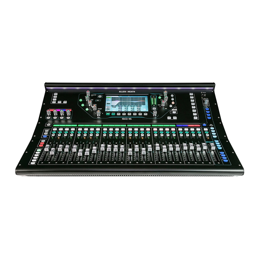
Where necessary, it will be noted which model is being discussed. The differences are as follows: Model Faders Preamps XLR Outputs SoftKeys SoftRotaries SQ-5 16+master 16+talkback SQ-6 24+master 24+talkback Reference Guide V1.0.1…
-
Page 7: Updating Firmware
3. Updating firmware 1) Insert a new or formatted USB drive into the SQ-Drive port on the front of the 2) Press the ‘Utility’ screen key, and select ‘USB Utility’. 3) In the ‘Status/Format’ tab, both windows should say ‘Ready’. If they do not, you will need to ensure you are in the correct USB mode.
-
Page 8: Operational Overview
4. Operational Overview 4.1 Physical control of the SQ Keys – All keys are labelled, and most illuminate to show when they are active. All perform specific functions, aside from the ‘SoftKeys’ which are user assignable. Faders – There are 6 layers of assignable fader strips. For all inputs and FX returns the fader controls the send level of this channel to the selected mix.
-
Page 9: Channel Types
4.2 Channel types Input channels – 48 input channels with processing. These can be sourced from local, remote or digital connections, and mixed to any output. Main LR – This is the main mix. All post-fader modes and options follow this mix. Mix channels –12 stereo mix channels with processing that can be used as either auxiliaries or groups.
-
Page 10: On-Screen Title Bar
Keyboard – An on-screen keyboard is displayed when entering names or numbers. Touch and hold ‘^’ (shift) to enable caps lock. Touch ‘Apply’ or ‘OK’ to set the name or number. Touch the ‘X’ at the top right of the keyboard to close it. Confirmation –…
-
Page 11: Home Screen
4.5 Home screen current/next scene screen title SQ-Drive connected firmware version This is the first screen shown when powering on the SQ. It is also shown when no channels are selected, and no other screens are active. The firmware version is displayed below three buttons. ‘Shut Down’…
-
Page 12: Basic Workflow Concepts
4.7 Basic workflow concepts • Press ‘LR’, ‘Mix’ or ‘FX’ key to present send levels for the selected Mix on the Fader Strips. Use the layer keys to move through the 6 layers of faders and adjust individual levels. The Master strip controls the master send level of the selected Mix/FX. •…
-
Page 13: Screens Reference
4.8 Screens Reference Screen Key Option 1/Left Tabs Option 2/Top Tabs Name Preamp (input), Ext In (mix) Processing Bank/Processing View Gate (input), Insert (mix) Insert (input), GEQ (mix) Name Direct Out/Group/Aux Snd/FX Snd Routing DCA/Mute Assign Bank/Assign and Level View Mix Sends Matrix Sends Input Meters…
-
Page 14: Connections
5. Connections inputs outputs SLink footswitch I/O Port network 5.1 Local inputs Mono mic/line (XLR female) – These are numbered and accept balanced mic or line level signal. Gain, Pad and 48v Phantom Power are controlled digitally. Talkback (XLR female) – Identical to mono mic/line inputs. Intended for communication from the desk position, but can also be used as an additional input.
-
Page 15: Slink
5.3 SLink Digital multichannel (Neutrik etherCON) – For expanding the SQ using Allen & Heath Remote Audio Units. Mode switchable between dSnake, DX and gigaACE protocols. SLink does not support multiple protocols on a single connection. Firmware V1.0.1 does not support the connection of secondary (daisy chained) units. …
-
Page 16: I/O Patching
6. I/O Patching There are two ways to patch channels, either in the Preamp section of the channel processing screen, or in the I/O screen. For patching multiple channels, it is easiest to use the I/O patching screen. Press the ‘I/O’ screen key to display the patching matrix. •…
-
Page 17: Local
6.1 Local The local input and output options in the I/O screen match the analogue input and output socket labels on the SQ. 6.2 SLink The SLink port is compatible with dSnake, DX and gigaACE. It switches between these modes, so multiple protocols over a single connection are not supported. The current mode is shown on the tab unless nothing is connected, in which case ‘Not Connected’…
-
Page 18: Usb
6.4 USB destination type/channel Main R out to SQ-Drive (USB) channel 2 source type/channel USB patching is for SQ-Drive or USB-B streaming connections. SQ-Drive uses input and output USB channels 1 to 16 and USB-B uses input and output USB channels 1 to 32. …
-
Page 19: Processing
7. Processing Press any ‘Sel’ key to select a channel. The physical controls and keys around the touchscreen will illuminate to show they are active, and can be used to adjust parameters for the selected channel. Press the ‘Processing’ screen key to display the processing ‘bank view’. channel name channel source preamp…
-
Page 20: Preamp
7.1 Preamp source select preamp control channel delay stereo image Source Select – • Touch the source type to select from a list of sources. Unassigned = Channel has no source. Local Socket = A socket on the rear of the SQ. SLink Socket = A device connected to the SLink port (AR, AB and DX units.
-
Page 21
Socket Preamp – • Touch and hold the ‘48V’ button to switch phantom power on or off (channel will be automatically muted when switching this). • Touch the ‘Pad’ button to switch the -20dB pad in or out. • Select ‘Gain’ or ‘Trim’ parameters to adjust using the touchscreen rotary. Gain can also be adjusted using the dedicated physical control. -
Page 22: Gate (Input Channels)
7.2 Gate (input channels) side chain source and filter gate parameters and graph histogram Switch the Gate in or out using either the on-screen ‘In’ button or the physical Gate ‘In’ key (to the left of the dedicated Gate threshold rotary). Side Chain –…
-
Page 23: Insert
• Adjust parameters by touching to select and then using the touchscreen rotary. Gate threshold also has a dedicated rotary. Attack = 50µs to 300ms Hold = 10ms to 5secs Release= 10ms to 1sec Threshold = -72dB to +18dB Depth = 0dB to 60dB Histogram –…
-
Page 24
Send – Select destination type and channel for the insert send. Return – Select source type and channel for the insert return. Send/Return types = Local Socket, SLink Socket, USB Port, IO Port, FX Unit Operating level – Select from line level options to match insert type. Digital = Uncompensated, for use with digital I/O. -
Page 25: Geq (Mix Channels)
7.4 GEQ (mix channels) All mix channels feature a 28-band stereo graphic EQ. With a mix channel selected, and GEQ active, the green ‘In’ LED in the GEQ section (below the PEQ rotaries) will illuminate. To make adjustments, touch the on-screen fader for each band and use the touchscreen rotary.
-
Page 26: Hpf And Peq
7.5 HPF and PEQ PEQ display HPF display band frequency bandwidth HPF control gain HPF — In order of processing, the High Pass Filter (HPF) is located post-preamp (as in the channel overview). It is displayed in the EQ screen for convenience. •…
-
Page 27: Compressor
7.6 Compressor side chain control compressor mode parallel controls histogram compressor parameters and graph Switch the Compressor in or out using either the on-screen ‘In’ button or the physical Compressor ‘In’ key (to the left of the dedicated Compressor threshold rotary). Side Chain –…
-
Page 28
Parameters – • Adjust parameters by touching to select and then using the touchscreen rotary. Attack = 30µs to 300ms Release= 50ms to 2secs Ratio = 1:1 (no compression) to Infinity (limiting) Threshold = -46dB to +18dB Gain (make-up gain) = 0dB to +18dB Graph –… -
Page 29: Routing
8. Routing Press any ‘Sel’ key to select a channel, then press the ‘Routing’ screen key to display the routing ‘bank view’. This shows an overview of 8 channels at once, with the selected channel highlighted. channel name direct out/mix source settings DCA/mute group assign drag left/right send levels and group assignments…
-
Page 30: Direct Out
8.1 Direct out direct out source individual direct output level follow options This screen shows the direct output level for the selected channel, as well as the global direct out settings which affect all channels. The currently selected channel is displayed on the left.
-
Page 31: Mix Send And Balance Settings
8.2 Mix send and balance settings Mix channels have different buttons in place of the ‘Dir Out’ button found on the input channels, touch this to see the following options. Main – (‘Main Snd’) • Touch the ‘Output Bal’ value and adjust using the touchscreen rotary to adjust the output balance.
-
Page 32: Dca/Mute Groups
8.3 DCA/Mute Groups assign selected channel to DCA view all channels assigned to this DCA assign selected channel to mute group view all channels assigned to this mute group All DCA and Mute Group assignments for the selected channel are displayed, with the currently selected channel displayed to the left.
-
Page 33: Send Levels And Mix Assignments
8.4 Send levels and mix assignments mix sends pre/post button drag left/right assign to mix pan (stereo mixes) send level This screen displays all sends and mix assignments for the selected channel. • Touch and drag left or right to view all mixes and sends. •…
-
Page 34: Metering
9. Metering 9.1 PAFL LED Meter The 12 segment LED metering on the surface of the SQ to the right of the touchscreen displays level metering for the PAFL bus. By default, with no PAFL keys active, this displays the main LR mix level. …
-
Page 35: Rta
9.3 RTA left right frequency bands • RTA follows PAFL selection and settings. • Displays the levels of 31 frequencies with fixed 1/3 oct bandwidth. • The meter for the prominent frequency of either left or right is shown in red. System setup — By connecting a measurement microphone and ‘listening’…
-
Page 36: Chromatic Channel Metering
9.5 Chromatic Channel Metering The Chromatic Channel Metering displays the information of a high-resolution meter in the space of a single LED. It can depict a much greater range of levels than a traditional meter and behaviour is customisable in the ‘Channel Meters’ tab. default brightness/intensity ‘threshold’…
-
Page 37: Fx Engines
10. FX Engines 10.1 Using FX buses and returns The SQ has four FX send buses which, in SQ’s default state, send to the first four FX engine slots (these are preloaded with useful FX pre-sets). These buses can be used in the same way as any of the mix buses: •…
-
Page 38: Loading Units And Pre-Sets
10.2 Loading units and pre-sets Pressing the ‘FX’ screen key displays the front/rear of the currently selected FX engine, with other loaded FX units and empty slots on the left of the screen. global tempo panel view FX parameters loaded FX empty slots FX PEQ send level/settings…
-
Page 39: Sending To Fx From Other Sources
10.4 Sending to FX from other sources Mix->Return — As well as sending using the four FX buses, you can send to the FX engines using mixes, allowing you to send to any of the 8 FX engines using ‘sends on faders’.
-
Page 40: Fx Levels And Peq
10.5 FX Levels and PEQ When routed as ‘Mix -> Return’, the PAFL, Mute and Level settings for the currently selected FX engine slot are displayed at the bottom of the screen for both the FX send and FX return. •…
-
Page 41: Saving And Recalling Shows/Scenes
11. Saving and Recalling Shows/Scenes All the settings in SQ can be stored and recalled in either ‘Scenes’ or ‘Show’ files. Scenes are intended for recall during use, whilst a Show file contains everything for an event or particular set up. Show files should also be used to backup a configuration or transfer it to another unit.
-
Page 42: Scene Manager
11.1 Scene manager The scene manager allows the storing, recalling and deletion of scenes. store/recall settings edit scene name scene name scene number To store all current mix settings in a new slot, touch any empty slot then: • Touch the ‘Store’ button to save with the name ‘Scene [x]’. •…
-
Page 43: Global Filter
11.2 Global Filter Global scene filters are always active, and affect which settings are changed when recalling a scene. mix filters input filters other filters routing filters • Touch any filter button to switch between ‘Allow’ and ‘Block’. • Blocked parameters will not be affected when recalling scenes. …
-
Page 44: Show Manager (Usb)
11.4 Show manager (USB) A ‘Show’ allows you to store all SQ settings and scenes at once, and is used to back- up the mixer settings, or transfer them to another SQ, using SQ-Drive. The show manager is located in the ‘Utility’ screen, in the ‘USB Data’ tab. rename show shows on SQ-Drive store/recall actions…
-
Page 45: Setup
12. Setup 12.1 Strip assign All fader strips on the SQ are freely assignable. Press the ‘Setup’ screen key, touch the ‘Surface’ tab then touch the ‘Strip Assign’ channel types SQ channels drag ‘n’ drop surface layers surface fader strips tab.
-
Page 46: Input/Mix Stereo Assign
12.2 Input/Mix stereo assign To use channels as stereo channels throughout the mixer, they must first be switched into stereo mode. In the ‘Setup’ screen, touch the ‘Mixer Config’ tab, then touch either ‘Input Stereo’ or ‘Mix Stereo’. stereo mode mono mode apply changes mono aux…
-
Page 47: Mix Bus Configuration
12.3 Mix bus configuration The 12 stereo mixes can be switched between group and auxiliary modes under the ‘Bus Config’ tab. groups auxiliaries apply changes • Touch either the ‘Number or Groups’ value or the ‘Number of Auxes’ value, then adjust using the touchscreen rotary. •…
-
Page 48: Softkeys/Softrotaries
12.4 SoftKeys/SoftRotaries SoftKeys and SoftRotaries (SQ-6) allow you to customise surface controls of the SQ. Press the ‘Setup’ screen key, then touch the ‘Surface’ tab followed by the ‘Soft Controls’ tab to view and adjust SoftKey and SoftRotary assignments. control type control option 1 control option 2 SoftKey selection…
-
Page 49
Possible SoftKey assignments Control Type Control Option 1 Control Option 2 Colour Unassigned Channel Mute All audio channels Mute Group Mute Groups 1 to 8 DCA Mute DCA’s 1 to 8 Tap Tempo Left, Right, Left & Right FX engines 1 to 8 Global Tap Tempo Recall Scene All saved scenes… -
Page 50: Footswitch
12.5 Footswitch Connecting a single or dual, momentary or latching footswitch with a TS or TRS ¼” jack plug to the ‘Footswitch’ socket allows hands free control of the SQ. In the ‘Setup’ screen, touch the ‘Surface’ tab then the ‘Footswitch’ tab to display and adjust the footswitch settings and assignments.
-
Page 51: Surface Preferences
12.6 Surface Preferences Press the ‘Setup’ key, then touch the ‘Surface’ tab followed by the ‘Surface Prefs’ tab to see the surface preferences. This screen can also be accessed by pressing the ‘Brightness’ button on the ‘Home’ page. • Touch the ‘Confirm Scene Operations’…
-
Page 52: Pafl
12.7 PAFL The Pre/After Fade Listen settings affect the behaviour of the PAFL bus which is routed to the SQ headphone output and displayed on the 12 segment LED meter as well as being routed to the SQ’s RTA. Press the ‘Setup’ screen key, then touch the ‘Audio’ tab, followed by the ‘PAFL’ tab to display and adjust settings.
-
Page 53: Audio Sync And Aes Sample Rate
12.8 Audio Sync and AES sample rate Press the ‘Setup’ screen key, then touch the ‘Audio’ tab followed by the ‘Audio Sync Opts’ tab to see sync and AES digital output sample rate options. • Touch the ‘Audio Clock Source’ value to select a source. Internal = Sync to the internal audio clock.
-
Page 54: Talkback Settings
12.9 Talkback settings Talkback is used to enable the engineer to communicate via the audio outputs. When the ‘Talk’ key is pressed, the talkback source is routed to all assigned mixes. Press the ‘Setup’ screen key, then touch the ‘Audio’ tab followed by the ‘Talkback’ tab to view and adjust the talkback settings.
-
Page 55: Signal Generator
12.10 Signal Generator The signal generator can be used to send a signal to a mix for level configuration or used in conjunction with the and a measurement microphone to check the frequency response of a system. Press the ‘Setup’ screen key, then touch the ‘Audio’ tab followed by the ‘SigGen’ tab to view and adjust the signal generator settings.
-
Page 56: Network Setup
12.11 Network Setup For use with any control over Ethernet, such as wireless control or use with MIDI over TCP/IP, the SQ must be connected as a device on a network. With default settings, the SQ will automatically connect to any network which uses DHCP to assign IP addresses, and will be seen by any apps running on devices connected to the same network.
-
Page 57: Sq-Drive And Usb-B
13. SQ-Drive and USB-B SQ-Drive and USB-B make use of the same audio technology inside SQ, so they run exclusively from one another. Therefore, you must choose which mode the SQ is running in before recording or playing back any audio. There are other bandwidth intensive tasks (such as formatting an SQ-Drive) that also require the mode to be changed.
-
Page 58: Sq-Drive Stereo Recording And Playback
13.1 SQ-Drive stereo recording and playback Press the ‘Utility’ screen key then touch the ‘SQ-Drive’ tab followed by the ‘Stereo’ tab to show the SQ-Drive Stereo record/playback screen. record/playback meters record controls and time record file error count playback file playback mode playback controls and time playback position…
-
Page 59
Playback – • Touch the ‘Stereo Playback’ file name value. Then touch the ‘Playback’ or ‘Recording’ button to view files in each folder (recordings you have made with the SQ are displayed in the ‘Recordings’ folder). • Touch a track to select it, then scroll through the list of tracks using the touchscreen rotary if needed. -
Page 60: Sq-Drive Multitrack Recording And Playback
13.2 SQ-Drive multitrack recording and playback Press the ‘Utility’ screen key then touch the ‘SQ-Drive’ tab followed by the ‘Multitrack’ tab to show the SQ-Drive Multitrack record/playback screen. SQ-Drive status track selection record/playback meters playback mode record/playback controls and time error count Recording — •…
-
Page 61
The ‘Errors’ counter increments with any detected writing error. So it is a good measure of USB device suitability for recording. Not all USB devices are capable of the high bandwidth used by the SQ-Drive multitrack recording feature. For best results when multitrack recording direct to USB, use a high- speed external hard drive rather than a USB stick/’pen’… -
Page 62: Connecting To A Computer
13.3 Connecting to a computer To stream audio to and from a computer, it needs to be connected to the SQ using a USB-A to USB-B cable. SQ conforms to USB 2.0 standards, so it is recommended to use a high-speed USB cable.
-
Page 63: Midi And Daw Control
14. MIDI and DAW Control When connected to a computer either via USB or TCP/IP, the SQ sends and receives MIDI control messages. These can be broken down into two sets of bi-directional messages. Those that are used to control the SQ, and those used to control external software or equipment. The MIDI protocol for control and automation of the SQ is outside of the scope of this guide.
-
Page 64: Midi Fader Strips
14.2 MIDI fader strips The SQ has 32 available MIDI fader strips that can be assigned anywhere in the fader strip layers. These transmit standard MIDI messages over USB and TCP/IP when ‘Mute’, ‘Sel’ or ‘PAFL’ keys are pressed, or when the fader strip fader is adjusted. They also respond to the same messages.
-
Page 65: Mix/System Reset
15. Mix/System Reset 15.1 Reset Mix Settings To return the SQ to a known state (to ‘zero the desk’), press the ‘Scenes’ screen key, then touch the ‘Scene Manager’ tab. Touch and hold the ‘Reset Mix Settings’ button and a confirmation pop-up will be displayed. …
-
Page 66: System Reset
15.2 System reset To perform a full system reset, hold the EQ ‘In’ and ‘HF’ keys when powering on the SQ. This will clear all mix settings and all saved data, including Shows/Scenes and Libraries, so back-up any data you wish to keep using SQ-Drive. 15.3 Fader Calibration Occasionally faders can become misaligned, this can happen for many reasons and is usually nothing to be concerned about.
-
Page 67: Block Diagrams
16. Block Diagrams Sidechain Sidechain INPUT CHANNEL x 48 Configurable Mono / Stereo Skt, I/O Port, USB or RackFX INSERT MUTE FADER ASSIGN+PAN WIDTH TRIM GATE COMP DELAY IP to MAIN +4/-10 IP to GRP Stereo ch only Post-Preamp Post-Ins A Post-PEQ Post-Delay IP to AUX/FX…
-
Page 68
TALKBACK SIG GEN To: GRP Assign to: GRP MUTE Sine (Sweep 20-20kHz) MAIN White Noise MATRIX MAIN Pink Noise MATRIX Bandpass Noise (Sweep) Press to TALK FX SEND RackFX x8 FX RETURN x8 METER Strip METER Send > Return FX FADER in-place MUTE… -
Page 69: Specifications
Nominal +4dBu ST1, ST2 / 0dBu ST3 Trim +/-24dB Maximum Input Level (ST1, ST2 / ST3) +22dBu / +18dBu Input Impedance >7kΩ Outputs 1-12 (SQ-5) and 1-14 (SQ-6) Balanced, XLR Outputs A and B Balanced 1/4″ TRS Jack Source Patchable Output Impedance <75Ω…
-
Page 70
<0.7mS, Local Mic Input routed to Main L/R. (Direct, No EQ/ Effects) Operating Temperature Range 0 deg C to 40 deg C (32 deg F to 104 deg F) Mains Power 100-240V AC, 50/60Hz Max Power Consumption SQ-5/SQ-6 75W / 90W Reference Guide V1.0.1… -
Page 71
Input Processing Source CH1-48 Fully patchable USB Global Source SQ-Drive or USB-B Streaming Polarity Normal/Invert Trim -24 to +24dB High Pass Filter 12dB/octave 20Hz – 2kHz Insert (Pre EQ/Comp) Fully Patchable Delay Up to 341ms Gate Patchable Sidechain Sidechain filter Hi-pass (20-5k), Band-pass (120-10k), Lo-pass (120-20k) Threshold / Depth -72dBu to +18dBu / 0 to 60dB… -
Page 72
Mix Processing Insert (Pre EQ/Comp) Fully Patchable Delay Up to 682ms 28 bands 31Hz-16kHz, +/-12dB Gain, Constant 1/3 oct As Input PEQ Compressor As Input Compressor Internal FX 8 x RackExtra FX engine, Send>Return or Inserted (4 dedicated FX bus) SMR Reverb, Gated Reverb, Stereo Tap Delay, ADT, Symphonic Types Chorus, Flanger… -
Page 73
Size and Weight SQ-5 Width x Depth x Height Desk mounted 440 x 514.9 x 198 mm (17.3″ x 20.3″ x 7.8″) Packed in shipping box 610 x 680 x 360 mm (24″ x 26.8″ x 14.2″) Unpacked weight 10.5 kg (23.1 lbs) Packed weight 14 kg (30.9 lbs) -
Page 74: Warranty Information
18. Warranty Information Limited One Year Manufacturer’s Warranty Allen & Heath warrants the Allen & Heath -branded hardware product and accessories contained in the original packaging («Allen & Heath Product”) against defects in materials and workmanship when used in accordance with Allen &…
This manual is also suitable for:
Sq-6
Инструкции по эксплуатации
Укажите здесь торговую марку и тип
В настоящее время вы находитесь на странице с руководствами . Выберите одну из категорий продуктов, чтобы быстро найти нужное руководство . Не удалось найти нужный продукт ? Тогда попробуйте вбить в строку поиска и модель, чтобы найти нужное руководство . На ManualsPDF.ru в настоящее время имеется 227 руководств , разделенных на 8. Самые популярные категории продуктов :
- Смесители
- Без категории
- DJ-система
Самые популярные продукты из на сегодня:
- Allen & Heath Qu-16
- Allen & Heath SQ-5
- Allen & Heath QU-24
 05:46
05:46
iLive Getting Started
 16:12
16:12
Allen & Heath iLive: обучающий семинар (Артем Годин)
 09:37
09:37
Cеминар по пультам Allen & Heath iLive T
 10:06
10:06
Allen&Heath — iLive — T112
 07:30
07:30
iLive Surface Basics Faders
 03:57
03:57
bongkar motorized fader mixer ALLEN & HEATH iLive T112
 11:55
11:55
Allen&Heath — iLive — FX Routing Control
Руководство Пользователя Октябрь…
Руководство пользователя, Октябрь 2007
- Изображение
- Текст
1
Руководство Пользователя
Октябрь 2007

2
Системное описание iLive
Содержание
1. Приветствие………………………………………………………………………………………………………..3
2. Обзор…………………………………………………………………………………………………………………..4
3. Системная спецификация…………………………………………………………………………………..4
4. Перед использованием системы……………………………………………………………………….6
5. Первый запуск…………………………………………………………………………………………………….6
6. Выключение системы…………………………………………………………………………………………7
7. Ключевые компоненты системы……………………………………………………………………….7
8. Базовая информация о консоли………………………………………………………………………..7
9. Фейдерная Линейка…………………………………………………………………………………………..8
• Вход………………………………………………………………………………………………………………9
• Группа…………………………………………………………………………………………………………………9
• Aux……………………………………………………………………………………………………………….……10
• Мастер………………………………………………………………………………………………………………10
• Посыл на FX………………………………………………………………………………………………………11
• Возврат FX…………………………………………………………………………………………………………11
• Матрица……………………………………………………………………………………………………………12
• DCA……………………………………………………………………………………………………………………12
• MIDI Контроллер……………………………………………………………………………………………..12
10. Система мониторинга…………………………………………………………………………………………..13
11. Приборная Панель……………………………………………………………………………………………….13
• Входные каналы……………………………………………………………………………………………….14
• Микс каналы……………………………………………………………………………………………………..20
12. Другие выключатели на консоли…………………………………………………………………………22
13. Меню Utility…………………………………………………………………………………………………………..24
• Блокировка консоли…………………………………………………………………………………………24
• Изменение пользователя………………………………………………………………………………..25
• Операционная Система……………………………………………………………………………………25
• Сеть……………………………………………………………………………………………………………………26
• Диагностика ………………………………………………………………………………………….…………28
• Конфигурация…………………………………………………………………………………………………..30
14. Настройка желаемого Микшера………………………………………………………………………….33
• Конфигурация шин……………………………………………………………………………………………34
• Настройка консоли………………………………………………………………………………………….35
• Имена и цвета……………………………………………………………………………………………….….36
• Метры……………………………………………………………………………………………………………….37
• PAFL……………………………………………………………………………………………………………….…..38
• Направления (Routing)………………………………………………………………………………….….39
• Выходы………………………………………………………………………………………………………….…..41
• FX………………………………………………………………………………………………………………….…….41
• Сцены…………………………………………………………………………………………………………………42
15. Использование DCA………………………………………………………………………………………………43
16. Сортировка миксов………………………………………………………………………………………….….…43
17. Описание модулей…………………………………………………………………………………………….….44
18. Объяснение EtherSound…………………………………………………………………………………….….45
19. Основы IP Адресации…………………………………………………………………………………………….46

3
Приветствие
Спасибо за проявленный интерес к Системе цифрового микширования Allen&Heath iLive.
Прежде чем начать работу с Системой, для полного ее понимания и больших возможностей
управления и настройки, пожалуйста, внимательно прочитайте данное Руководство,
состоящее из следующих частей:
Быстрый Старт – Информация необходимая для начала работы с Системой.
Руководство – Описание Системы с детальной информацией
Веб-ресурс – Постоянно обновляющийся ресурс, с информацией и программами,
доступный по адресу
www.ilive.com
.
Если вы не нашли необходимой информации,
пожалуйста свяжитесь с вашим региональным дилером компании Allen&Heath.
Знакомство с iLive
iDR10 – 19 дюймовый сценический рэк, в котором находится сердце системы iLive, микшерный
модуль iDR-64 DSP, модули CPU и RAB, по средствам которых осуществляется управление аудио
интерфейсами. По сути – это и есть микшер, управляемый по средствам консоли или PC. В рэке
доступно 10 дополнительных слотов под модули ввода/вывода. Модули бесперебойного питания
расположены в задней части рэка. iDR10 приспособлен для использования в прокате и турах.
Внешние и внутренние стенки надежно укреплены, предусмотрен блокиратор колес. Передняя и
задняя стенки рэка снимаются.
Контроль над системой осуществляется по сетевому TCP/IP
протоколу. Предусмотрено три сетевых порта, для коммутации
консоли, компьютера и других сетевых приборов. Отдельно
выведены порты подключения PL-Anet и MIDI контроллеров.
iLive –
это
консоль
для
Живого
Микширо
вания, которая работает со сценическим
рэком iDR10 MixRack. Консоль
выпускается в различных размерах, в зависимости от количества фейдеров. Консоль
оборудована входными разъемами для подключения модулей входа/выхода, таких как в
сценическом рэке (нужно для дополнительных внешних обработок или источников фоновой
музыки). Консоль выполнена в аналоговом стиле, с поддержкой цветных ЖК-дисплеев и
цветного TFT дисплея «Touch screen» (нажатием отдаются команды). Доступен слот для
подключения 2U резервного питания iPS10 (при необходимости).

4
2.Обзор
Системный Рэк
I. Модули аналоговых входов.
Балансные XLR. 1 модуль — 8 входов
II. Модули аналоговых выходов.
Балансные XLR. 1 модуль — 8
выходов
III. Модуль цифровых аудио выходов. 1
модуль – 8 выходов (4 стерео) в 3
форматах цифрования (AES3; SPDIF;
optical).
IV. Модуль Цифрового Аудио Процессора
iDR-64 (DSP).
V. Модуль управления аудио (ESA; ESB),
system clock,выход на наушники.
VI. Опция EtherSound .(ESA – для
соединения рэка и консоли (и далее
в Brake-out box); ESB – для расширения системы и объединением нескольких
рэков (и далее в Brake-out box)). ES Routing оставляет 33-62 каналы для dir out,
insert sends, talkback и PAFL.
VII.
Коннекторы внешней синхронизации DARS (Digital Audio Reference Signal).
VIII.
Сетевая опция EtherNet служит для соединения и объединения консоли и рэка,
или нескольких консолей ( FOH и мониторный ).
IX. MIDI коннекторы
X. PL-Anet коннекторы.
С задней стороны – модули включения (2)
Не показаны – модуль цифрового входа (идент. выходу), новый модуль
мульти входа (16 in по 8 пар, позволяет в одном рэке уместить каналов больше
чем 64, модуль цифрового выхода (16 назначаемых каналов) с поддержкой
ADAT, Aviom и Hearback (мониторинг) и iDR expand (модули iDR8)).

5
Консоль
(задняя панель)
A – USB коннекторы
B – Коннекторы ламп освещения.
С – Запасные коннекторы для подключения PSU (Power Switch Unit).
D – Коннекторы для Talkback и внешнего PFL
E – Внутренний PSU модуль
F – Remote Audio модуль (ESA, MIDI … )
G – EtherNet
H – Модули входа/выхода.
Не показаны – Коннекторы USB и выход на наушники на передней панели консоли.
3.
Системная спецификация
Система iLive может обрабатывать 64 входа и 32 микса с полной обработкой, двумя
шинами стереоэффектов (в будущем планируется еще 4). Аудио сигнал подключается в
модули входа/выхода в системном рэке, на задней панели консоли или через сетевую
шину EtherSound. Конфигурация шин может настраиваться в зависимости от нужд
пользователя – 28 шин миксов и 4 шины для мониторинга. Система может быть
расширена при помощи сетевой шины EtherSound.

6
4. Перед использованием Системы
Перед началом использования системы, проверьте все компоненты и модули на наличие и
правильную установку (модули должны крепко сидеть в слотах). В каждом системном рэке
должны быть установлены модули CPU (центральный процессор), REMOTE AUDIO
(управление аудио), DSP (цифровой звуковой процессор) и один модуль PSU (питание), а в
консоль, как минимум должен быть установлен модуль CPU.
Система подключаются следующим образом:
Сетевым кабелем CAT5, через гнездо Network соедините модули CPU на консоли и в рэке.
Сетевым кабелем CAT5, вход EtherSound IN (модуль RAB) на консоли и EtherSound A OUT
(модуль RAB) в системном рэке. (В случае если в консоли отсутствует данный модуль,
соединение может и не устанавливаться, однако в консоли при этом никакого аудио сигнала
не будет.)
Подключите питание консоли и системного рэка в соответствующую электрическую сеть.
5. Первый Запуск
Для включения системы нажмите кнопки On/Off на задней панели системного рэка и консоли. В
подтверждении включения загорится синий индикатор. Так же загорятся различные индикаторы
на модулях с передней стороны. На модуле CPU расположены два синих индикатора, для
каждого из блоков питания. На модуле RAB и DSP также расположены синие индикаторы питания.
В момент включения, на всех выходах срабатывает функция MUTE (глушение). Это необходимо
для того что бы оградить усиливающую аппаратуру и динамики от нежелательных звуков
(щелчков, клипов). MUTE отключится когда DSP будет полностью готов к работе. Активность
функции MUTE указывают красные индикаторы на модулях в системном рэке. Такая же схема
глушения в момент включения срабатывает и на консоли, а с полной готовностью отключается.
Запуск системы занимает около минуты. Системный рэк готов обрабатывать аудио уже через 20
секунд после включения. Параметры контроллеров консоли загружаются через сеть около 40
секунд. Во время загрузки, на дисплее (Touch Screen) , будет отображаться процесс запуска
системы. BIOS загрузит операционную систему LINUX, которая в свою очередь загрузит программу.
Когда программа будет загружена, система начнет работать в соответствии с контроллерами
консоли. Когда система будет загружена, будут установлены параметры на момент последнего
выключения системы.
Если системе не удается установить сетевое соединение, проверьте секцию EtherNet и IP
адресации.

Выключение системы, Ключевые компоненты системы, Базовая информация о консоли
Страница 7
- Изображение
- Текст
7
6. Выключение системы
Перед выключением системы нажмите кнопку Power Down в меню UTILITY. Программа ответит,
что система может быть выключена. После этого нажмите кнопки ON/OFF на задней панели
системного рэка и консоли.
Модуль питания определяет наличие в сети питания и посылает процессору сигнал, если модуль
определит нехватку питания, включится батарея, которая позволит сохранить последние
установки, что бы к ним вернуться после загрузки. В случае исчезновения питания во время
перемещения информации с внешнего USB накопителя, существует вероятность, что файлы будут
повреждены.
7. Ключевые компоненты системы
В системе iLive используется три отдельных компьютерных системы, объединенных Ethernet – это
iDR10 Mix Rack, Surface Console и Touch Screen. Каждая имеет собственную ОС, хранящуюся на
диске. Каждая система обновляется независимо.
8. Базовая информация о консоли
Для того что бы в дальнейшем проще получать доступ к функциям и информации, нужно усвоить
несколько базовых правил. LCD-дисплей показывает информацию необходимую для
микширования, настройки системы, и группировки информации с графической поддержкой
процессов микширования и назначений.
Когда ни одна из кнопок под дисплеем не нажата, на нем
отображается информация, относящаяся к любой линейке с
активным
зеленым
индикатором SEL. В этом случае на
дисплее отображается графическая раскладка линейки —
Thumbnails
.
В случае если ни один канал не выбран, на
верхней информационной строке дисплее отображается
‘No
Channel Selected’
.
Входы и выходы отображаются модулями
в цепи прохождения сигнала, каналы эффектов –
процессорами эффектов, каналы DCA – назначением на DCA.
Информация на дисплее может изменяться как с приборной
панели консоли, так и непосредственно с дисплея. Нажатие
на отдельный блок на дисплее или на кнопку с
зеленым
индикатором SEL на приборной панели открывает детальный вид выбранного модуля. Параметры
на экране могут изменяться нажатием на нужное значение и вращением поворотного энкодера
справа внизу от дисплея, позволяющего выбрать одно из возможных вариантов значений.
Передвижение кнопкой SEL от модуля к модулю отображается на дисплее соответствующей
информацией. В случае необходимости вернуться к исходному виду линейки нажмите кнопку
‘Return to Thumbnails’
в верхнем правом углу дисплея
.
Передвижение кнопкой SEL (над
фейдером) от линейки к линейке на дисплее будет изменяться лишь информация относительно
выбранного канала, вид будет оставаться прежним. К примеру, работая с эквалайзером на одном
канале, вы перемещаетесь на следующий канал – дисплей отобразит эквалайзер следующего
выбранного канала. В случае если вы переместитесь на отличный канал, выход например, вы
получите, либо последний выбранный вид выхода, либо Thumbnails выхода. Итак,
зеленый
SEL
включает информацию о выбранном модуле или канале, в случае если никакая другая функция
под дисплеем не выбрана. Если одна из функций под дисплеем выбрана, она является для
дисплея приоритетной и будет отображаться, несмотря на активный SEL.

8
9. Канальная Линейка
Канальные линейки распределяются по консоли на три банка, каждый по четыре слоя
(LAYERS A;B;C;D), переключатели которых расположены рядом с каждым банком.
Канальная линейка включает в себя моторизованный фейдер, кнопку MIX (назначение),
кнопку MUTE, кнопку PAFL, кнопку SEL (выбор канала), вращательный энкодер (по сути,
цифровой потенциометр без ограничения значения), ЖК-дисплей (7 цветов) и Индикатор
уровня сигнала.
Назначение каналов на заданные ячейки осуществляется при помощи Surface strips
channel assigment в меню Surface. Block assigment позволяет выбрать от и до которого
канала применяется назначение. Имя и цвет канала присваивается в меню Names and
Colors.
Каждый канал может быть назначен как Input (mono/stereo (назначается в MIX SETUP)),
Group, AUX, MAIN, FX Return, FX Send, Matrix, DCA, MIDI Controller.
Кнопкой
SEL
, канал выбирается для редакции в нем блоков в цепи прохождения сигнала и
отображения на сенсорном мониторе.
Кнопка
MIX
может быть использована для показания маршрута линейки, и уровней.
Альтернативно, если выбран выход (AUX, GP, MAIN),
MIX
может быть использован для
назначения каналов на шину, удержанием кнопки Assign и нажатием кнопки
MIX
на
линейке, т. е. для назначения каналов в подгруппы или aux — выбрать группу, нажать
MIX
,
удерживая кнопку Assign выбрать отправляемые в группу каналы.
Энкодер — по умолчанию управляет панорамой канала, в сочетании с кнопкой Rotary Shift
управляет уровнем посыла на SUB-Mani Out. Положение энкодера определяется по шкале
L – R, L – C – R на ЖК-дисплее.
PAFL включает мониторинг на данный канал
.
(Пре-mute)
ЖК-дисплей отображает информацию о назначении, номере, функции энкодера и текущем
статусе канала.
Метр информирует об активности сигнала на канале.

Вход В случае, когда канальная линейка назначена на вход, в…
Страница 9
- Изображение
- Текст
9
Вход
В случае, когда канальная линейка назначена на вход, в верхней части ЖК-дисплея будет гореть
индикатор IP (Input), а в нижней части значок ON, обозначающий, что канал отправлен на
выбранную шину (
MIX
). По умолчанию – Main.
Фейдер – громкость канала (указано в нижнем левом углу ЖК-дисплея).
MUTE — глушение канала.
PAFL — включает мониторинг канала на индикаторе уровня сигнала и в системе наушников на
консоли и системном рэке.
Кнопка
SEL
используется для редактирования канала.
Энкодер – Панорама. В случае стерео – баланс.
Кнопка
MIX
– рутинг (Routing,маршрут).
Группа
В случае, когда канальная линейка назначена на группу, в верхней части ЖК-дисплея будет гореть
индикатор GP (Group), а в нижней значок ON, обозначающий, что канал отправлен на выбранную
шину (
MIX
). По умолчанию – Main.
Фейдер – громкость канала (указано в нижнем левом углу ЖК-дисплея).
MUTE — глушение канала.
PAFL — включает мониторинг канала на индикаторе уровня сигнала и в системе наушников на
консоли и системном рэке.
Кнопка
SEL
используется для редактирования канала.
Энкодер – Панорама. В случае стерео – баланс.
Кнопка
MIX
– рутинг и назначение каналов на данную группу (ASSIGN+
MIX
). Назначение
определяется на LCD-мониторе в окне Routing, по значку ON в нижней части ЖК-дисплея и по
светящемуся голубому индикатору
MIX
.

В случае, когда канальная линейка назначена на AUX, в верхн…
Страница 10
- Изображение
- Текст
10
AUX
(Посыл)
В случае, когда канальная линейка назначена на AUX, в верхней части ЖК-дисплея будет гореть
индикатор AUX .
Фейдер – громкость канала (указано в нижнем левом углу ЖК-дисплея). Фейдеры отправленных
на AUX каналов – становятся их посылами.
MUTE — глушение канала.
PAFL — включает мониторинг канала на индикаторе уровня сигнала и в системе наушников на
консоли и системном рэке.
Кнопка
SEL
используется для редактирования канала.
Энкодер – по умолчанию отключен.
Кнопка
MIX
– рутинг и назначение каналов на данный AUX (ASSIGN+
MIX
). Назначение
определяется на LCD-мониторе в окне Routing, по значку ON в нижней части ЖК-дисплея и по
светящемуся голубому индикатору
MIX
. Фейдеры назначенных каналов становятся посылом.
Main
(Мастер Выход)
В случае, когда канальная линейка назначена на Main, в верхней части ЖК-дисплея будет гореть
индикатор Main .
Фейдер – громкость канала (указано в нижнем левом углу ЖК-дисплея).
MUTE — глушение канала.
PAFL — включает мониторинг канала на индикаторе уровня сигнала и в системе наушников на
консоли и системном рэке.
Кнопка
SEL
используется для редактирования канала.
Энкодер – по умолчанию отключен.
Кнопка
MIX
– рутинг и назначение. (По умолчанию входы, группы и возвраты назначены на Main ).

Комментарии
АЛЛЕН ЭНД ХИТ ЛИМИТЕД — компания из Пенрина, графство Корнуолл, Англия, специализирующаяся на производстве аудиомикшерных пультов. Allen & Heath также производит системы управления звуком для промышленных установок и DJ-микшеры для ночных клубов. Allen & Heath является частью Audiotonix Group. Их официальный webсайт АЛЛЕН ХИТ.com
Каталог руководств пользователя и инструкций для продуктов ALLEN HEATH можно найти ниже. Продукция ALLEN HEATH запатентована и зарегистрирована под торговыми марками АЛЛЕН ЭНД ХИТ ЛИМИТЕД
Контактная информация:
Тел: +44 1326 372070 XNUMX XNUMX
Адрес компании:
Аллен энд Хит Лимитед Керник Индастриал Эстейт
Penryn Cornwall TR10 9LU ВеликобританияТеl + 44 (0) 1326 372070
Регистрационный номер компании:
4163451 Зарегистрировано в Англии и Уэльсе

Найти
Цифровая микшерная система ALLEN HEATH S7000 Перед началом работы посетите веб-сайт www.allen-heath.com, чтобы получить последнюю версию встроенного программного обеспечения dLive и документацию. Информация о продукте Allen & Heath dLive Surface — это цифровой микшерный пульт, доступный в трех моделях — S3000, S5000 и S7000. Функция консоли определяется прошивкой, которая ее запускает. Прошивка есть…
Подробнее «Руководство пользователя цифровой микшерной системы ALLEN HEATH S7000»
Allen Heath PlayDifferently MODEL1 Введение MODEL 1 — это 6-канальный профессиональный микшер, разработанный для использования в клубной среде профессиональными ди-джеями и продюсерами, но он одинаково удобен в небольшой студии или в качестве компактного внешнего пульта вещания, не требующего микрофонных входов. Он уникален тем, что предлагает шесть полнофункциональных…
Подробнее «Allen Heath PlayDifferently MODEL1 Руководство пользователя»
Руководство по началу работы с GPIO GPIO — это интерфейс ввода-вывода общего назначения для управления интеграцией систем AHM, Avantis или dLive и оборудования сторонних производителей. Он имеет 8 оптронных входов и 8 релейных выходов на разъемах Phoenix, а также два выхода +10 В постоянного тока. К AHM можно подключить до 8 модулей GPIO,…
Подробнее «Универсальный интерфейс ввода-вывода ALLEN HEATH GPIO для дистанционного управления. Руководство пользователя»
ALLEN HEATH IP1 Селектор аудиоисточника и пульт дистанционного управления IP1 / EU Fitting Примечание. IP1 является частью серии дистанционных контроллеров Allen & Heath IP. Live требуется прошивка V1.60 или выше для работы с IP1. Этот продукт должен быть установлен профессиональным установщиком или квалифицированным электриком. Установка пульта дистанционного управления Эта модель…
Подробнее «Селектор аудиоисточника ALLEN HEATH IP1 и руководство по эксплуатации пульта дистанционного управления»
Руководство пользователя пульта дистанционного управления ALLEN HEATH IP6 Ограниченная гарантия производителя сроком на один год Allen & Heath гарантирует, что оборудование и аксессуары марки Allen & Heath, содержащиеся в оригинальной упаковке («Продукт Allen & Heath»), не будут иметь дефектов материалов и изготовления при использовании в соответствии с требованиями Allen. & Heath’s руководства пользователя, технические характеристики и другие…
Подробнее «Руководство пользователя пульта дистанционного управления ALLEN HEATH IP6»
ALLEN HEATH AHM 16, AHM 32 Аудио матричные процессоры ВАЖНО – Прочтите перед началом работы Инструкции по технике безопасности Перед началом работы прочтите Важные инструкции по технике безопасности, напечатанные на листе, прилагаемом к оборудованию. Для вашей собственной безопасности и безопасности оператора, технической бригады и исполнителей соблюдайте все инструкции и учитывайте все предупреждения, напечатанные на листе…
Подробнее «Руководство пользователя матричных аудиопроцессоров ALLEN HEATH AHM 16, AHM 32»
GL2400 16-канальный микшер для живых выступлений ALLEN&HEATH GL2400 РУКОВОДСТВО ПОЛЬЗОВАТЕЛЯ Публикация AP5597 https://tm.by – Ограниченная годовая гарантия TM.by На данное изделие распространяется гарантия на отсутствие дефектов материалов или изготовления сроком на один год с даты покупки первоначальным владельцем. Для обеспечения высокого уровня производительности и надежности…
Подробнее «ALLEN HEATH GL2400 16-канальный микшер для живых выступлений. Руководство пользователя»
ALLEN HEATH ZED-6 6-канальный микшер Live + Recording Руководство пользователя Благодарим вас за покупку Allen & Heath ZED-6. Мы рекомендуем вам прочитать все это руководство пользователя, чтобы получить максимальную отдачу от вашего микшера, и после прочтения сохраните его для дальнейшего использования. В этот комплект входит: Смеситель ZED-6 IEC …
Подробнее «ALLEN HEATH ZED-6 6 Channel Live + Recording Mixer Руководство пользователя»
ZEDi-8 8-канальный микшер для прямых трансляций и записи Руководство пользователя ZEDi-8 8-канальный микшер для прямых трансляций и записи Благодарим вас за покупку Allen & Heath ZEDi-8. Мы рекомендуем вам прочитать все это руководство пользователя, чтобы получить максимальную отдачу от вашего микшера, и после прочтения сохраните его для дальнейшего использования. Входит в этот…
Подробнее «ALLEN HEATH ZEDi-8 8-канальный микшер для живых выступлений и записи. Руководство пользователя»
ALLEN HEATH ZED6FX 6-канальный записывающий микшер Live Plus Благодарим вас за покупку Allen & Heath ZED-6FX. Мы рекомендуем вам прочитать все это руководство пользователя, чтобы получить максимальную отдачу от вашего микшера, и после прочтения сохраните его для дальнейшего использования. В этот комплект входят: Микшер ZED-6FX IEC C5 Сеть …
Подробнее «Руководство пользователя 6-канального записывающего микшера ALLEN HEATH ZED6FX Live Plus»