Инструкция по эксплуатации Фиат Стило
Навигация по разделам руководства с помощью меню.
Знакомство с автомобилем
- Знаки и таблички
- Система Fiat CODE, Ключи Фиат Стило
- Электронная охранная сигнализация
- Ремни безопасности
- Безопасная перевозка детей, детские кресла, Isofix
- Замок зажигания Фиат Стило
- Передняя панель салона (торпеда)
- Комбинация приборов
- Приборы
- Многофункциональный дисплей
- Многофункциональный дисплей с изменяемой конфигурацией
- Контрольные лампы и предупреждающие сигналы
- Регулировка сидений
- Система отопления/кондиционирования воздуха
- Отопление и вентиляция
- Кондиционер с ручной регулировкой
- Климат-контроль с раздельной регулировкой
- Подрулевые переключатели
- Система поддержания постоянной скорости (круиз-контроль)
- Круиз-контроль с радаром
- Плафон освещения салона
Органы управления - Оборудование салона
- Прозрачная крыша Skywindow
- Двери
- Багажник
- Капот
- Багажник на крыше и крепление для перевозки лыж
- Фары
Антиблокировочная система (АБС) - Система поддержания курсовой устойчивости (BP)
Противопробуксовочная система ASR - Европейская бортовая система диагностики E0BD (модификации с бензиновым двигателем)
- Передние и боковые подушки безопасности
- Аудиосистема
- Дополнительное оборудование, приобретаемое автовладельцем
- Электроусилитель рулевого управления «Dualdrive»
- Датчики парковочные
- На бензоколонке
- Охрана окружающей среды
- Easy Gо (система опознавания)
Правильная эксплуатация автомобиля
- Запуск двигателя
- На стоянке
- Механическая коробка передач
- Система Selespeed Селеспид
- Безопасное вождение
- Экономичное и грамотное вождение
- Экономить топливо и беречь природу
- Буксировка прицепа
- Зимние шины
- Цепи противоскольжения
- Консервация автомобиля
- Полезные аксессуары
В непредвиденной ситуации
- Аварийный запуск двигателя
- Запуск двигателя от резервной аккумуляторной батареи (прикуривание)
Инерционный запуск двигателя
Если спустило колесо - Замена лампы
- Если не горит фара. Замена ламп.
- Если не горит задний фонарь
- Если не работает освещение салона. Как заменить лампочки
- Перегорел предохранитель, замена
- Если разрядился аккумулятор
- Если надо поднять автомобиль с помощью домкрата
- Буксировка автомобиля Fiat Stilo
- В случае аварии
Техническое обслуживание автомобиля Fiat Stilo
- Плановое техобслуживание (ТО)
- Программа планового техобслуживания
- Программа ежегодного обслуживания
- Дополнительные мероприятия
- Контроль уровней
- Воздушный фильтр
- Фильтр цветочной пыльцы
- Фильтр дизельного топлива
- Аккумуляторная батарея
- Электронные блоки управления
- Колеса и шины
- Шланги резиновые
- Стеклоочистители ветрового и заднего стекол
Омыватели фар - Кузов
- Салон
Технические характеристики Fiat Stilo
- Идентификационные данные
- Код двигателя — модификация кузова
- Двигатель
- Свечи зажигания
- Трансмиссия
- Тормоза
- Передняя и задняя подвеска
- Рулевое управление
- Колеса
Габаритные размеры Fiat Stilo
- Эксплуатационные характеристики
- Масса
- Заправочные емкости
- Жидкости и смазочные материалы
- Расход топлива
- Выброс углекислого газа
- Радиочастотный пульт дистанционного управления. Сертификация
- Электронный ключ CID (Customer Identification Device). Сертификация
Мультимедийное руководство по техническому обслуживанию и ремонту Fiat Stilo, многоязычный интерфейс (русского нет).
- Автор: —
- Издательство: —
- Год издания: —
- Страниц: —
- Формат: NRG
- Размер: 160,7 Mb
Руководство на итальянском языке по техническому обслуживанию и ремонту Fiat Stilo с дизельным двигателем.
- Автор: —
- Издательство: —
- Год издания: —
- Страниц: 121
- Формат: PDF
- Размер: 38,3 Mb
Руководство по эксплуатации и ремонту Fiat Stilo с 2001 года выпуска с бензиновыми и дизельными двигателями.
- Автор: —
- Издательство: Гуси-Лебеди
- Год издания: 2011
- Страниц: 422
- Формат: PDF
- Размер: 416,2 Mb

Не так давно бороздил просторы интернета в поисках мануалов Fiat Stilo что бы почерпнуть полезную информацию о своем авто, в результате нашел несколько:
Официальный, наверняка у всех в бордачке валяется такой. Но вдруг потребуется, а в гараж идти не хочется
официальный
narod.ru/disk/19030506001/FIAT%20STILO.djvu.html
dl.dropbox.com/u/34096599/fiat/FIAT%20STILO.djvu
Руководство по ремонту и обслуживанию Fiat Stilo с дизельным двигателем 1.9 JTD
все изложено на доступном Итальянском языке =)
narod.ru/disk/19251951001…tilo%20Diesel%20.pdf.html
dl.dropbox.com/u/34096599…t%20Stilo%20Diesel%20.pdf
Fiat Stilo руководство по эксплуатации,
книжка на 422 страницы 2011 года, автор Гусь С.В
Гусь С.В
narod.ru/disk/19111894001…F%20Fiat%20Stilo.pdf.html
dl.dropbox.com/u/34096599…%D1%8F%20Fiat%20Stilo.pdf
Если найду еще что то, то неприменимо добавлю. Надеюсь пригодится кому-нибудь.
-
nekesha
- Администратор
- Сообщения: 1668
- Зарегистрирован: 17 дек 2014, 03:43
- Благодарил (а): 2 раза
- Поблагодарили: 6 раз
Fiat Stilo с 2001г
Сообщение nekesha » 28 фев 2015, 23:09
Руководство по эксплуатации, техобслуживанию и ремонту Fiat Stilo
 2792 просмотра")
Выпуск: с 2001 года
Язык: Русский
Формат: PDF
Размер: 81,5 Мб
Скачать документацию Fiat Stilo
для распаковки архива используйте пароль — avtoproblem-net.ru
28 посетителей на сайте. Из них:
Список пользователей
vcvcvc
Был(a) в сети 25 минут назад
mob-3
Был(a) в сети 1 час назад
manuk
Был(a) в сети 1 час назад
Magua
Был(a) в сети 1 час назад
ANRI
Был(a) в сети 2 часа назад
che125
Был(a) в сети 2 часа назад
гоша
Был(a) в сети 3 часа назад
георги
Был(a) в сети 3 часа назад
dsn999
Был(a) в сети 4 часа назад
daci
Был(a) в сети 4 часа назад
andd02
Был(a) в сети 6 часов назад
serg010
Был(a) в сети 6 часов назад
Altron
Был(a) в сети 6 часов назад
HJW
Был(a) в сети 6 часов назад
sktem
Был(a) в сети 6 часов назад
e706co
Был(a) в сети 7 часов назад
g6guhef
Был(a) в сети 7 часов назад
Lemming
Был(a) в сети 7 часов назад
sanek51
Был(a) в сети 8 часов назад
Susell
Был(a) в сети 9 часов назад
serg264
Был(a) в сети 9 часов назад
feca
Был(a) в сети 9 часов назад
Mitsuba
Был(a) в сети 10 часов назад
vedat
Был(a) в сети 10 часов назад
alxbk
Был(a) в сети 10 часов назад
mariolo
Был(a) в сети 11 часов назад
василь
Был(a) в сети 13 часов назад
Kurasan
Был(a) в сети 13 часов назад
arsrum
Был(a) в сети 13 часов назад
eddol
Был(a) в сети 14 часов назад
bmm-71
Был(a) в сети 14 часов назад
Masterm
Был(a) в сети 17 часов назад
iay10
Был(a) в сети 21 час назад
ghost20
Был(a) в сети 22 часа назад

Скачать бесплатно книгу Fiat Stilo руководство по ремонту и эксплуатации.
Автор: Гусь С.В.
Название:Fiat Stilo руководство по ремонту и эксплуатации
Издательство: Минск УП «Гуси-Лебеди»
ISBN: 985-455-117-3
Год: 2011
Формат: PDF
Размер: 525МВ
Страниц: 422
Язык: Русский
Производственно-практическое издание:
Руководство по ремонту и экспулатации автомобилей Fiat Stilo выпуск c 2001г.в.
Бензиновые двигатели:
1.2л (80 л.с.)
1.4л (95 л.с.)
1.6л (103 л.с.)
1.8л (133 л.с.)
2.4л (170 л.с.)
Дизельные двигатели:
1.9 JTD 8V (80 л.с.)
1.9 JTD 16V (116 л.с.)
Скачать Fiat Stilo руководство по ремонту и эксплуатации
Все права принадлежат авторам, файл не размещается физически у нас и был найдет на просторах интернета.
Если это нарушает Ваши права, напишите нам и мы удалим ссылку.
- Fiat
- STILO
- книга
- руководство
- скачать
Смотреть руководство для Fiat Stilo (2002) ниже. Все руководства на ManualsCat.com могут просматриваться абсолютно бесплатно. Нажав кнопку «Выбор языка» вы можете изменить язык руководства, которое хотите просмотреть.

MANUALSCAT | RU
Вопросы и ответы
У вас есть вопрос о Fiat Stilo (2002), но вы не можете найти ответ в пользовательском руководстве? Возможно, пользователи ManualsCat.com смогут помочь вам и ответят на ваш вопрос. Заполните форму ниже — и ваш вопрос будет отображаться под руководством для Fiat Stilo (2002). Пожалуйста, убедитесь, что вы опишите свои трудности с Fiat Stilo (2002) как можно более детально. Чем более детальным является ваш вопрос, тем более высоки шансы, что другой пользователь быстро ответит на него. Вам будет автоматически отправлено электронное письмо, чтобы проинформировать вас, когда кто-то из пользователей ответит на ваш вопрос.
Задать вопрос о Fiat Stilo (2002)
- Бренд:
- Fiat
- Продукт:
- Автомобили
- Модель/название:
- Stilo (2002)
- Тип файла:
- Доступные языки:
- турецкий
Сопутствующие товары Fiat Stilo (2002)
 Loading…
![]()
Dear Customer,
Thank you for selecting Fiat and congratulations on your choice of a Fiat Stilo.
We have written this handbook to help you get to know all your new Fiat Stilo features and use it in the best possible way. You should read it right through before taking the road for the first time.
You will find information, tips and important warnings regarding the driving of your car to help you derive the maximum from your Fiat Stilo technological features.
You are recommended to read carefully the warnings and indications, marked with the respective symbols, at the end of the page:
personal safety;
the car’s wellbeing;
environmental protection.
The enclosed Warranty Booklet lists the services that Fiat offers to its Customers:
the Warranty Certificate with terms and conditions for maintaining its validity
the range of additional services available to Fiat Customers.
Best regards and good motoring!
This Owner Handbook describes all Fiat Stilo versions. As a consequence, you should consider only the information which is related to the engine and bodywork version of the car you purchased.

MUST BE READ!
REFUELLING
Petrol engines: only refuel with unleaded petrol with octane rating (RON) not less than 95 conforming to the Eu-
Kropean specification EN 228.
Diesel engines: only refuel with diesel fuel conforming to the European specification EN590. The use of other products or mixtures may irreparably damage the engine with invalidation of the warranty due to the damage caused.
ENGINE STARTING
Petrol engines with mechanical gearbox: make sure that the handbrake is engaged; set the gearshift lever to neutral; fully depress the clutch without pressing the accelerator, then turn the ignition key to AVV and release it as soon as the engine has started.
Petrol engines with Selespeed gearbox: keep the brake pedal fully depressed; turn the ignition key to AVV and release it as soon as the engine has started; the transmission sets to neutral automatically.
Diesel engines: turn the ignition key to MAR and wait for the warning lights Yand m to go off; turn the ignition key to AVV and release it as soon as the engine has started.
PARKING ON FLAMMABLE MATERIAL
While working, the catalyst develops a very high temperature. Do not park the car over grass, dry leaves, pine needles or any other inflammable materials: risk of fire.
RESPECTING THE ENVIRONMENT
The car is fitted with a system that allows continuous diagnosis of the components correlated with emissions to ensure better respect for the environment.

ELECTRICAL ACCESSORIES
If, after buying the car, you decide to add electrical accessories (that will gradually drain the battery), visit a Fiat Dealership. They can calculate the overall electrical requirement and check that the car’s electric system can support the required load.
CODE card
Keep the code card in a safe place, not in the car. The code card shall be used for requesting additional keys.
SCHEDULED SERVICING
Correct maintenance of the car is essential for ensuring it stays in tip-top condition and safeguards its safety features, its environmental friendliness and low running costs for a long time to come.
THE OWNER HANDBOOK CONTAINS…
… information, tips and important warnings regarding the safe, correct driving of your car, and its maintenance. Pay particular attention to the symbols » (personal safety) # (environmental protection) ! (the car’s wellbeing).

|
DASHBOARD |
AND CONTROLS |
|
SAFETY |
DEVICES |
|
CORRECT USE |
OF THE CAR |
|
WARNING LIGHTS AND |
MESSAGES |
|
IN AN |
EMERGENCY |
|
CAR |
MAINTENANCE |
|
TECHNICAL |
SPECIFICATIONS |
|
INDEX |
DASHBOARD AND CONTROLS
|
DASHBOARD ……………………………………………………………… |
5 |
|
INSTRUMENT PANEL ………………………………………………… |
6 |
|
SYMBOLS ……………………………………………………………………… |
8 |
|
THE FIAT CODE SYSTEM…………………………………………… |
8 |
|
THE KEYS …………………………………………………………………….. |
10 |
|
ALARM …………………………………………………………………………. |
17 |
|
IGNITION SWITCH…………………………………………………….. |
20 |
|
INSTRUMENTS…………………………………………………………….. |
21 |
|
MULTIFUNCTION DISPLAY ……………………………………… |
23 |
|
TRIP COMPUTER ……………………………………………………….. |
34 |
|
SEATS ……………………………………………………………………………. |
37 |
|
HEAD RESTRAINTS …………………………………………………….. |
41 |
|
STEERING WHEEL ……………………………………………………… |
42 |
|
REARVIEW MIRRORS………………………………………………….. |
43 |
|
HEATING/CLIMATE CONTROL SYSTEM ……………….. |
44 |
|
HEATING AND VENTILATION ………………………………… |
46 |
|
MANUAL CLIMATE CONTROL SYSTEM ……………….. |
48 |
|
AUTOMATIC TWO-ZONE |
|
|
CLIMATE CONTROL SYSTEM ………………………………….. |
51 |
|
EXTERNAL LIGHTS …………………………………………………….. |
57 |
|
WINDOW WASHING………………………………………………… |
60 |
|
CRUISE CONTROL ……………………………………………………. |
64 |
|
CEILING LIGHTS ………………………………………………………… |
67 |
|
CONTROLS ………………………………………………………………… |
68 |
|
INTERIOR FITTINGS …………………………………………………… |
70 |
|
“SKYWINDOW”(BLADE SUNROOF) ……………………… |
74 |
|
DOORS ………………………………………………………………………… |
79 |
|
POWER WINDOWS ………………………………………………….. |
80 |
|
BOOT ……………………………………………………………………………. |
81 |
|
BONNET ………………………………………………………………………. |
92 |
|
ROOF RACK/SKI RACK …………………………………………….. |
93 |
|
HEADLIGHTS……………………………………………………………….. |
94 |
|
ABS SYSTEM ………………………………………………………………… |
95 |
|
ESP SYSTEM …………………………………………………………………. |
97 |
|
EOBD SYSTEM …………………………………………………………….. |
99 |
|
SOUND SYSTEM………………………………………………………….. |
100 |
|
ACCESSORIES PURCHASED BY THE OWNER ……… |
101 |
|
“DUALDRIVE” ELECTRIC POWER |
|
|
STEERING SYSTEM …………………………………………………….. |
102 |
|
PARKING SENSORS …………………………………………………… |
103 |
|
AT THE FILLING STATION ………………………………………. |
105 |
|
PROTECTING THE ENVIRONMENT ………………………. |
108 |
4
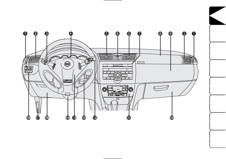
DASHBOARD
The presence and the position of the instruments and warning lights may vary according to the versions.
F0C0155m
fig. 1
1. Side window air vent — 2. Adjustable and swivel air vent — 3. External light stalk — 4. Instrument panel — 5. Adjustable and swivel air vent — 6. Hazard light switch — 7. Sound system controls — 8. Front passenger air bag — 9. Upper glovebox — 10. Lower glovebox — 11. Controls for heating, ventilation and climate control — 12. Windscreen/rear window wiper/trip computer stalk — 13. Ignition key and ignition switch — 14. Driver air bag — 15. Steering wheel locking/release stalk — 16. Control unit access door — 17. Bonnet opening lever — 18. Set of switches for lights and menu opening/setting.
|
DASHBOARD AND CONTROLS |
|
|
SAFETY |
DEVICES |
|
CORRECT USE |
OF THE CAR |
|
WARNING |
LIGHTS AND MESSAGES |
|
IN AN |
EMERGENCY |
|
CAR |
MAINTENANCE |
|
TECHNICAL |
SPECIFICATIONS |
|
INDEX |
5

|
DASHBOARD |
AND CONTROLS |
|
SAFETY |
DEVICES |
|
CORRECT USE |
OF THE CAR |
|
WARNING LIGHTS AND |
MESSAGES |
|
IN AN |
EMERGENCY |
|
CAR |
MAINTENANCE |
|
TECHNICAL |
SPECIFICATIONS |
|
INDEX |
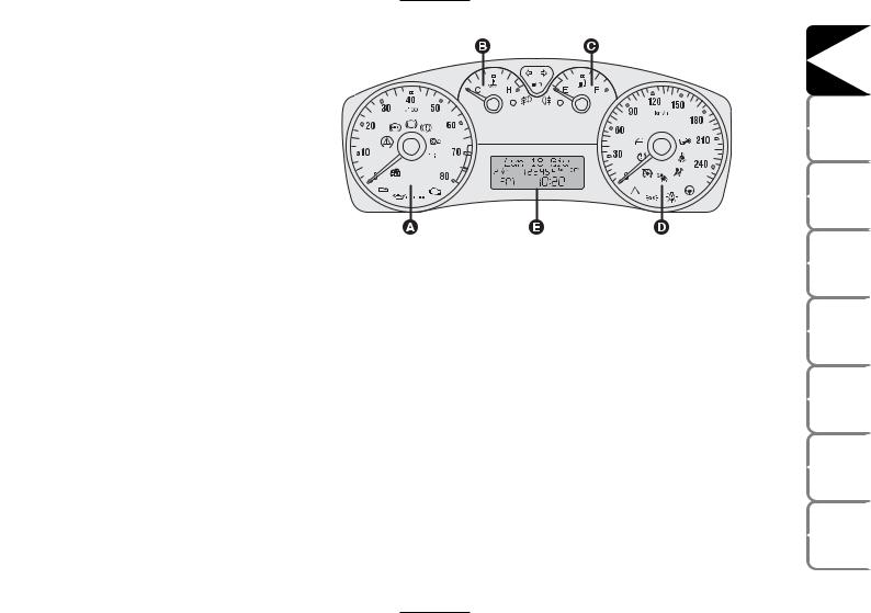
INSTRUMENT PANEL
fig. 2
fig. 3
1.416V — 1.616V — 1.816V versions A Rev counter
BEngine coolant temperature gauge and excessive temperature warning light
CFuel level gauge with reserve warning light
D Speedometer (speed indicator)
E Multifunction display.
The rev counter of versions with Selespeed transmission is fitted with warning light t.
1.9 Multijet versions A Rev counter
BEngine coolant temperature gauge and excessive temperature warning light
CFuel level gauge with reserve warning light
D Speedometer (speed indicator)
E Multifunction display.
The rev counter of versions with Selespeed transmission is fitted with warning light t.
6
2.420V Selespeed Abarth versions A Rev counter
BEngine coolant temperature gauge and excessive temperature warning light
CFuel level gauge with reserve warning light
D Speedometer (speed indicator)
E Multifunction display.
fig. 4
|
DASHBOARD AND CONTROLS |
|
|
SAFETY |
DEVICES |
|
CORRECT USE OF THE CAR |
|
|
F0C0523m |
LIGHTS AND MESSAGES |
|
WARNING |
|
|
IN AN |
EMERGENCY |
|
CAR |
MAINTENANCE |
|
TECHNICAL |
SPECIFICATIONS |
|
INDEX |
7
|
DASHBOARD |
AND CONTROLS |
|
SAFETY |
DEVICES |
|
CORRECT USE |
OF THE CAR |
|
WARNING LIGHTS AND |
MESSAGES |
|
IN AN |
EMERGENCY |
|
CAR |
MAINTENANCE |
|
TECHNICAL |
SPECIFICATIONS |
|
INDEX |
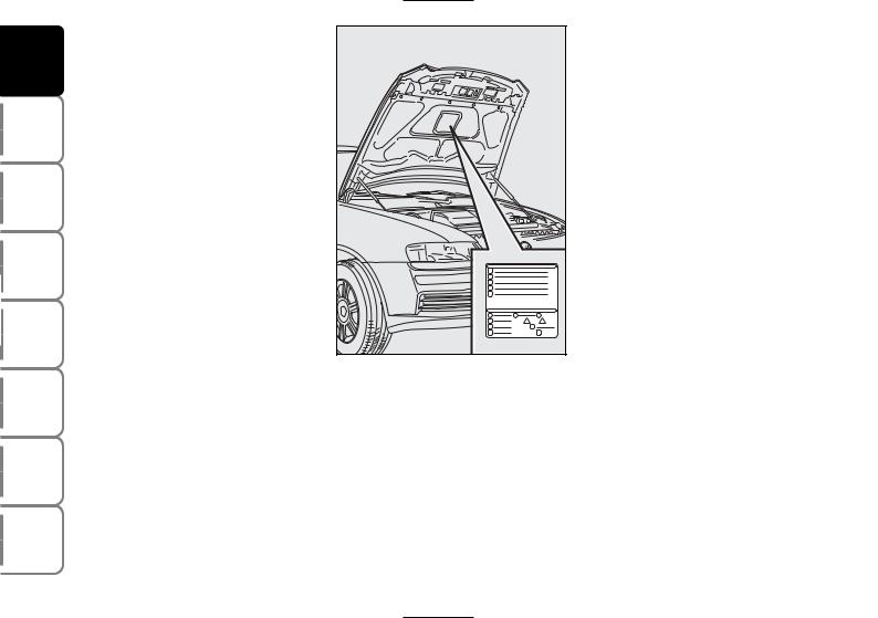
SYMBOLS
Special coloured labels have been attached near or actually on some of the components of your car. These labels bear symbols that remind you of the precautions to be taken as regards that particular component.
The plate summarising the symbols used can be found under the bonnet fig. 5.
THE FIAT CODE SYSTEM
To further protect you car from theft, it has been fitted with an engine immobilising system. This system is automatically activated when the ignition key is removed.
An electronic device, in fact, is fitted in each ignition key grip. The device transmits a radio-frequency signal when the engine is started through a special aerial built into the ignition switch. The modulate signal, which changes each time the engine is started, is the “password” by means of which the control unit recognises the key and enables to start the engine.
8
OPERATION
Each time the car is started turning the ignition key to MAR, the Fiat CODE system control unit sends a recognition code to the engine control unit to deactivate the inhibitor.
The code is sent only if the Fiat CODE system control unit has recognised the code transmitted from the key.
Each time the ignition key is turned to STOP, the Fiat CODE system deactivates the functions of the engine electronic control unit.
If the code has not been recognised correctly, the instrument panel warning light Ywill turn on.
In this case, the key should be moved to the STOP position and then back to MAR; if the lock continues, possibly try again with the other key provided with the car. If it is still not possible to start the car contact a Fiat Dealership.
IMPORTANT Every key has its own code, which must be memorised by the system control unit. To memorise new keys, up to a maximum of eight, apply solely to Fiat Dealership taking with you the CODE card and the keys, a personal identity document and the car’s ownership documents. The codes of the keys not provided during the new memorising procedure are erased from the memory. This is to ensure that any lost or stolen keys can no longer be used to start the car.
Warning light Ycoming on when driving
If the warning light Y turns on, this means that the system is running a selftest (for example for a voltage drop).
If the warning light Ycontinues to stay on, contact a Fiat Dealership.
The electronic components inside the key may be damaged if the key is submitted to sharp knocks.
|
DASHBOARD AND CONTROLS |
|
|
SAFETY |
DEVICES |
|
CORRECT USE |
OF THE CAR |
|
WARNING |
LIGHTS AND MESSAGES |
|
IN AN |
EMERGENCY |
|
CAR |
MAINTENANCE |
|
TECHNICAL |
SPECIFICATIONS |
|
INDEX |
9
![]()
|
DASHBOARD |
AND CONTROLS |
|
SAFETY |
DEVICES |
|
CORRECT USE |
OF THE CAR |
|
WARNING LIGHTS AND |
MESSAGES |
|
IN AN |
EMERGENCY |
|
CAR |
MAINTENANCE |
|
TECHNICAL |
SPECIFICATIONS |
|
INDEX |
THE KEYS
CODE CARD
Together with the keys you will receive the CODE card fig. 6 to be presented to Fiat Dealership when requesting additional keys.
IMPORTANT In order to ensure perfect efficiency of the electronic devices contained inside the keys, they should never be exposed to direct sunlight.
|
fig. 6 |
F0C0001m |
fig. 7 |
F0C0508m |
All the keys and the CODE card must be handed over to the new owner when selling the car.
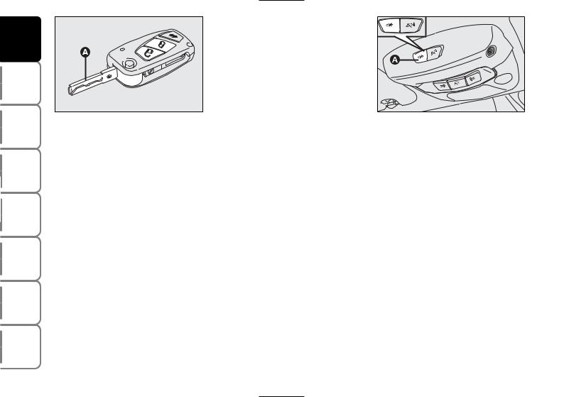
KEY WITHOUT REMOTE CONTROL (where provided)
The key is fitted with a metal insert A- fig. 7, operating:
the ignition switch
doors and tailgate locks
the fuel lid locking/unlocking (on versions featuring fuel filler cap with lock)
windows and Skywindow sunroof (where provided) opening/closing
the dead lock device (where provided)
the switch to deactivate the passenger’s air bag and rear side bags (where provided).
10
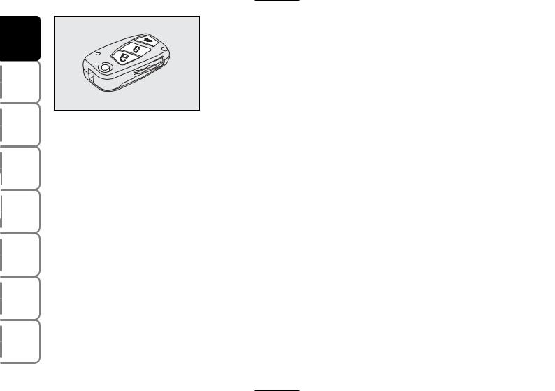
KEY WITH REMOTE CONTROL
The key is fitted with a metal insert A- fig. 8, operating:
the ignition switch
doors and tailgate locks
the fuel lid locking/unlocking (on versions featuring fuel filler cap with lock)
windows and Skywindow sunroof (where provided) opening/closing
the dead lock device (where provided)
the switch to deactivate the passenger’s air bag and rear side bags (where provided).
Button Ëfor remote unlocking of doors, tailgate and fuel filler cap. Button Áfor remote locking of doors, tailgate and fuel filler cap. Button R for remote opening of the tailgate. Button B for power-as- sisted opening of the metal insert A.
To refit the metal insert into the key grip, keep button B pressed and turn the metal insert in the direction shown by the arrow until hearing the click as it locks into place. Then release button B. Led C (where provided) comes on when sending the control to the alarm system receiver. To know the operating logics of the key with remote control and every possible and modifiable setting, see paragraph “Alarm” in this section.
If locking button Áis inadvertently pressed from the passenger compartment, when
getting out of the car only the doors being used will unlock; the tailgate will stay locked. To realign the system, press again the locking/unlocking buttons Á/ Ë.
WARNING
Button B-fig. 8 should only be pressed when the key is away from the body, in particular
from the eyes and from objects that can be spoilt (e.g. clothes). Make sure the key can never be touched by others, especially children, who may inadvertently press the button.
|
DASHBOARD AND CONTROLS |
|
|
SAFETY |
DEVICES |
|
CORRECT USE |
OF THE CAR |
|
WARNING |
LIGHTS AND MESSAGES |
|
IN AN |
EMERGENCY |
|
CAR |
MAINTENANCE |
|
TECHNICAL |
SPECIFICATIONS |
|
INDEX |
11
|
DASHBOARD |
AND CONTROLS |
|
SAFETY |
DEVICES |
|
CORRECT USE |
OF THE CAR |
|
WARNING LIGHTS AND |
MESSAGES |
|
IN AN |
EMERGENCY |
|
CAR |
MAINTENANCE |
|
TECHNICAL |
SPECIFICATIONS |
|
INDEX |
Opening the doors and the tailgate
Briefly press button Ë for remote unlocking of doors and tailgate and simultaneous alarm (where provided) deactivation, timed switching on of the internal ceiling lights and double flashing of direction indicators (for versions/markets where applicable).
Press button Ë for more than 2 seconds to open the windows and the Skywindow (where provided).
For Multi Wagon versions, pressing twice rapidly button R will open the rear window lid (where provided).
Once doors are unlocked, if you do not open one door or the tailgate within few seconds, the system will lock all doors/tailgate again automatically.
Doors will be unlocked automatically if the fuel inertial cut-off switch comes into operation.
Locking the doors and the tailgate
Briefly press button Á for remote locking of doors and tailgate and simultaneous alarm (where provided) activation, switching off of the internal ceiling lights and single flashing of direction indicators.
Press button Áfor more than 2 seconds to open the windows and the Skywindow (where provided). If the button is briefly pressed twice, the dead lock device is activated (see next paragraph “Dead lock device”).
If one or more doors are open locking will not be activated and the door led A-fig. 11 and direction indicators will flash rapidly. If only the tailgate is open the doors will lock.
12
Opening the tailgate by the remote control
Press and keep button R pressed to open the tailgate by remote control even if the alarm (where provided) is on.
Opening the tailgate is accompanied by the direction indicators flashing twice; closing is accompanied by a single flash only if the alarm is on.
If the alarm is on, when the tailgate is opened the alarm system switches off volumetric protection and the tailgate perimetral protection sensor.
IMPORTANT If the remote control does not work properly, it is still possible to carry out the above mentioned operations by using the metal insert of the key.
When closing the tailgate again, volumetric and perimetral protection sensors are restored.
Opening the rear heated window lid (MultiWagon versions)
On MultiWagon versions, pressing twice button R rapidly, obtains opening of the rear heated window lid (see fig. 10).
|
DASHBOARD AND CONTROLS |
|||
|
SAFETY |
DEVICES |
||
|
fig. 11 |
F0C0138m |
||
|
CORRECTUSE OF THE CAR |
|||
|
Leds on the driver’s door |
|||
|
When locking the doors, led A-fig. 11 |
WARNING |
ANDLIGHTS MESSAGES |
|
|
switches on for about 3 seconds and than |
|||
|
starts flashing (deterrence function). |
|||
|
Once doors are locked, if one or more |
|||
|
doors or the tailgate are not closed cor- |
ANIN |
EMERGENCY |
|
|
rectly, the led and direction indicators |
|||
|
start flashing quickly. |
|||
|
CAR |
MAINTENANCE |
||
|
TECHNICAL |
SPECIFICATIONS |
||
|
INDEX |
13
|
DASHBOARD |
AND CONTROLS |
|
SAFETY |
DEVICES |
|
CORRECT USE |
OF THE CAR |
|
WARNING LIGHTS AND |
MESSAGES |
|
IN AN |
EMERGENCY |
|
CAR |
MAINTENANCE |
|
TECHNICAL |
SPECIFICATIONS |
|
INDEX |
|
|
14 |
Request for additional remote controls
The system can recognise up to 8 remote controls. Should a new remote control be necessary, contact a Fiat Dealership, taking with you the CODE card, a personal identity document and the car’s ownership documents.
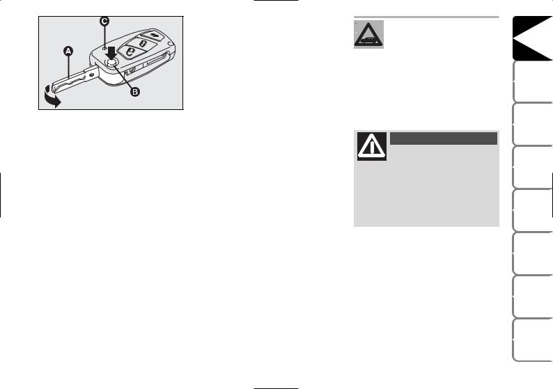
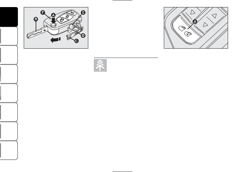
Replacing the battery of the key with remote control
If, when pressing button Ë, Á, or R, the led F-fig. 12 (where provided) on the key flashes briefly only once, the battery should be replaced with an equivalent one that can be purchased at common stores.
Battery replacement:
press button A and move the metal insert B to open position;
turn the screw C to : using a fine bit screwdriver;
take out the battery case D and replace the battery E making sure that the bias is correct;
re-insert the battery holder D in the
key and lock it turning the screw C to
;.
Used batteries are harmful to the environment. They should be disposed of as specified by law in the special containers
provided, or take them to a Fiat Dealership, which will deal with their disposal.
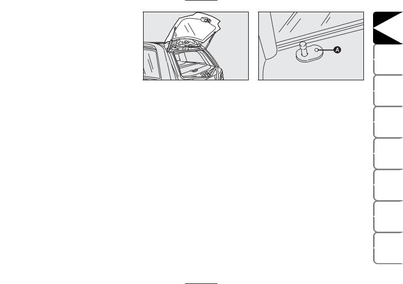
DEAD LOCK DEVICE (where provided)
This safety device enables to inhibit:
door internal handles and safety lock button;
button A-fig. 13 for locking/unlocking the doors, placed on the driver door panel mask;
thus hindering doors opening from inside the passenger’s compartment in case of attempt to break-into (e.g. window breaking).
The dead lock device guarantees the best protection against unwanted access. Therefore, it should be actuated every time the car is parked and left unattended.
WARNING
Once the dead lock device has been actuated, doors cannot be opened from inside the car
in any way whatsoever. For this reason, make sure there are no persons left inside the car.
WARNING
If the battery of the key with remote control is down, the dead lock device can only be activat-
ed through the metal insert of the key in the revolving plugs of the doors as described previously: in this case the dead lock device is active only on the rear doors.
Device activation
The device is automatically activated on every door in the following cases:
turning twice the key without remote control (where provided) in closing direction;
pressing twice button Áof the key with remote control.
Device activation is signalled by three flashings of the direction indicators and flashing of the led on the driver door panel (see the table on next page).
If one of the doors is not perfectly closed, the dead lock device will not activate, thus preventing that a person getting into the car from the open door remains blocked inside the passenger’s compartment when she/he closes the door.
Device deactivation
The device is deactivated automatically on every door in the following cases:
when unlocking the doors;
when unlocking only the driver’s door;
when turning the ignition key to MAR.
|
DASHBOARD AND CONTROLS |
|
|
SAFETY |
DEVICES |
|
CORRECT USE |
OF THE CAR |
|
WARNING |
LIGHTS AND MESSAGES |
|
IN AN |
EMERGENCY |
|
CAR |
MAINTENANCE |
|
TECHNICAL |
SPECIFICATIONS |
|
INDEX |
15

|
DASHBOARD |
AND CONTROLS |
|
SAFETY |
DEVICES |
|
CORRECT USE |
OF THE CAR |
|
WARNING LIGHTS AND |
MESSAGES |
|
IN AN |
EMERGENCY |
|
CAR |
MAINTENANCE |
|
TECHNICAL |
SPECIFICATIONS |
|
INDEX |
The main functions that can be activated with the keys (with or without remote control) are the following:
|
Type of |
Door opening |
Door closing |
Window and |
Window and |
Dead lock |
Tailgate |
||||||
|
key |
Skywindow |
Skywindow |
(where |
|||||||||
|
opening |
||||||||||||
|
opening (where |
closing (where |
provided) |
||||||||||
|
provided) |
provided) |
|||||||||||
|
Key without |
Key turning |
Key turning |
Turning (> 2 |
Turning (> 2 |
Double key rotation |
Key rotation |
||||||
|
remote |
counterclockwise |
clockwise |
seconds) in opening |
seconds) in closing |
in closing direction |
clockwise |
||||||
|
control |
(driver side) or |
(driver side) or |
position |
position (clockwise |
(clockwise driver |
|||||||
|
(where |
clockwise |
counterclockwise |
(counterclockwise |
driver side; |
side; counterclock- |
|||||||
|
provided) |
(passenger side) |
(passenger side) |
driver side; clock- |
counterclockwise |
wise passenger side) |
|||||||
|
wise passenger side) |
passenger side) |
|||||||||||
|
Key turning |
Key turning |
Turning (> 2 |
Turning (> 2 |
Double key rotation |
Key rotation |
|||||||
|
counterclockwise |
clockwise |
seconds) in opening |
seconds) in closing |
in closing direction |
clockwise |
|||||||
|
(driver side) or |
(driver side) or |
position (counter- |
position (clockwise |
(clockwise driver |
||||||||
|
clockwise |
counterclockwise |
clockwise driver |
driver side; |
side; counterclock- |
||||||||
|
Key with |
(passenger side) |
(passenger side) |
side; clockwise |
counterclockwise |
wise passenger side) |
|||||||
|
passenger side) |
passenger side) |
|||||||||||
|
remote |
||||||||||||
|
Pressing briefly |
Brief press on |
Prolonged pressing |
Prolonged pressing |
Double pressing on |
Prolonged press- |
|||||||
|
control |
||||||||||||
|
button Ë |
button Á |
(> 2 seconds) on |
(> 2 seconds) on |
button Á |
ing (> 2 seconds) |
|||||||
|
button Ë |
button Á |
on button R |
||||||||||
|
Direction |
Two flashings |
1 flashing |
Two flashings |
1 flashing |
3 flashings |
Two flashings |
||||||
|
indicators |
||||||||||||
|
flashing |
||||||||||||
|
(only with |
||||||||||||
|
key with |
||||||||||||
|
remote |
||||||||||||
|
control) |
||||||||||||
|
Led on |
Deterrence led |
Turned on fixed for |
Turning off |
Deterrence led |
Double flashing and |
Deterrent led |
||||||
|
driver door |
turning off |
approx. 3 seconds |
deterrence led |
flashing |
then deterrent led |
flashing |
||||||
|
and followed by de- |
flashing |
|||||||||||
|
terrence led flashing |
||||||||||||
16

ALARM
(where provided)
The alarm function is provided in addition to all remote control functions previously described and it is controlled by the receiver located under the dashboard, next to the fuse box.
WHEN THE ALARM IS
TRIGGERED
The alarm comes into action in the following cases:
unlawful opening of one of the doors, bonnet or boot (perimetral protection);
attempt to start the engine (turning the ignition key to MAR);
battery cable cutting;
presence of moving bodies in the passenger’s compartment (volumetric protection);
abnormal raising/sloping of the car.
Depending on the markets, the cutting in of the alarm causes operation of the siren and direction indicators (for about 26 seconds). The ways of operating and the number of cycles may vary depending on the markets.
A maximum number of sound/sight cycles is however envisaged.
Volumetric and anti-raising protections can be cut off by operating the front ceiling light controls (see paragraphs “Volumetric protection sensors” and “Anti-rais- ing sensor” on the following pages).
IMPORTANT The engine immobiliser function is guaranteed by the Fiat CODE system, which is automatically activated when the ignition key is removed.
HOW TO ACTIVATE THE ALARM
With the doors, bonnet and boot shut and the ignition key in the STOP position or with the key removed, point the key with remote control in the direction of the car, then press and release the button Á.
With the exception of certain markets, the system sounds a “beep” and the doors are locked.
Engagement of the alarm is preceded by a self-diagnostic test. If a fault is detected the system sounds a further warning “beep” and the display shows the relevant message (see section “Warning lights and messages”).
In this case, switch the alarm system off by pressing button Ë, check that the doors, bonnet and tailgate are properly shut, then switch the alarm on again by pressing button Á.
Otherwise, the door, bonnet or tailgate that is not shut properly will be excluded from the alarm system control.
|
DASHBOARD AND CONTROLS |
|
|
SAFETY |
DEVICES |
|
CORRECT USE |
OF THE CAR |
|
WARNING |
LIGHTS AND MESSAGES |
|
IN AN |
EMERGENCY |
|
CAR |
MAINTENANCE |
|
TECHNICAL |
SPECIFICATIONS |
|
INDEX |
17
|
DASHBOARD |
AND CONTROLS |
|
SAFETY |
DEVICES |
|
CORRECT USE |
OF THE CAR |
|
WARNING LIGHTS AND |
MESSAGES |
|
IN AN |
EMERGENCY |
|
CAR |
MAINTENANCE |
|
TECHNICAL |
SPECIFICATIONS |
|
INDEX |
If the doors, bonnet and boot are shut correctly and the control signal is repeated, the system self-diagnostics has detected a system operating fault. It is therefore necessary to contact Fiat Dealership.
IMPORTANT When operating the central door locking with the metal insert A- fig. 14 of the key, the alarm is not activated.
IMPORTANT The electronic alarm is built in compliance with the law and regulations of the different countries.
HOW TO DEACTIVATE THE ALARM
Press button Ë of the key with remote control.
The system will react as follows (with the exception of certain markets):
two brief flashes of the direction indicators;
two brief “beeps”;
door unlocking.
IMPORTANT Operating the central door locking with the metal insert of the key will not deactivate the alarm.
VOLUMETRIC PROTECTION SENSORS
The volumetric sensors are inside the front ceiling light in the passenger’s compartment. To make sure that the volumetric sensors are working properly, check that doors, boot, bonnet, windows and Skywindow (where provided) are shut.
Volumetric protection deactivation
If it is necessary to switch on the alarm when animals or people are in the car, press button A-fig. 15 on the front ceiling light to deactivate the volumetric protection.
Deactivation is needed also in the presence of additional independent heater and when it is switched on with the remote control.
Protection cut-out stays on until activating the central door opening again.
18
ANTI-RAISING SENSOR
The anti-raising sensor detects any abnormal car raising/sloping, even partial (e.g.: attempt to remove a wheel).
This sensor can detect the smallest car sideslip angle changes, both longitudinally and transversally.
Sideslip angle changes lower than 0.5°/min. (e.g.: slow tyre flattening) are not considered.
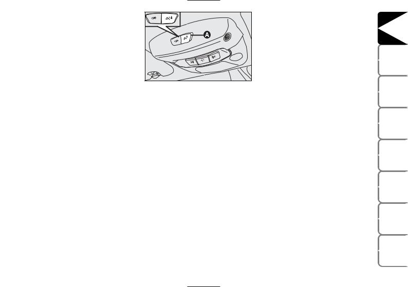
Anti-raising protection deactivation
To deactivate the anti-raising protection (for example when towing the car with alarm on) press button A-fig. 16 on the front ceiling light. Sensor cut-out stays on until activating the central door opening again.
INDICATIONS OF ATTEMPTS TO BREAK IN
Any attempt to break in is indicated by warning light Yon the instrument panel with the relevant message on the display (see section “Warning lights and messages”).
HOW TO CUT OFF THE ALARM SYSTEM
To deactivate the alarm system completely (for instance during prolonged inactivity of the car) simply lock the car turning the metal insert of the key with remote control in the lock.
IMPORTANT To cut-out the electronic alarm if remote control batteries are down or the system is failing, fit the key into the ignition switch and turn it to
MAR.
|
DASHBOARD AND CONTROLS |
|
|
SAFETY |
DEVICES |
|
CORRECT USE |
OF THE CAR |
|
WARNING |
LIGHTS AND MESSAGES |
|
IN AN |
EMERGENCY |
|
CAR |
MAINTENANCE |
|
TECHNICAL |
SPECIFICATIONS |
|
INDEX |
19
![]()
|
DASHBOARD |
AND CONTROLS |
|
SAFETY |
DEVICES |
|
CORRECT USE |
OF THE CAR |
|
WARNING LIGHTS AND |
MESSAGES |
|
IN AN |
EMERGENCY |
|
CAR |
MAINTENANCE |
|
TECHNICAL |
SPECIFICATIONS |
|
INDEX |
IGNITION SWITCH
The key can be turned to 3 different positions:
STOP: engine off, key can be removed, steering column locked. Certain electrical devices (e.g.: sound system, central door locking, electronic alarm, etc.) can work.
MAR: driving position. All electrical devices are powered.
AVV: engine starting.
The ignition switch is fitted with a safety mechanism that, in the event the engine is not started, compels the driver to turn the ignition key back to STOP before repeating the starting operation.
WARNING
If the ignition device is tampered with (e.g.: attempted theft), have it checked over by a Fiat
Dealership before restarting to drive.
WARNING
When getting out of the car, always remove the key to prevent any occupants from accidentally activating the controls. Remember to engage the handbrake and if the car is parked on uphill slope to engage the first gear. If the car is facing downhill, engage the reverse gear. Never leave unsupervised chil-
dren in the car.
STEERING COLUMN LOCK
Engaging
When the key is at STOP remove the key and turn the steering wheel until it locks.
Disengaging
Rock the steering wheel slightly as you turn the ignition key to MAR.
WARNING
It is absolutely forbidden to carry out whatever aftermarket operation involving steering
system or steering column modifications (e.g.: installation of anti-theft device) that could badly affect performance and safety, cause the lapse of warranty and also result in noncompliance of the car with homologation requirements.
WARNING
Never remove the ignition key while the car is moving.
The steering wheel would automatically lock as soon as you try to turn it. This also applies when the car is being towed.
20
INSTRUMENTS
|
fig. 18 |
F0C0530m |
fig. 18a |
F0C0527m |
|||
|
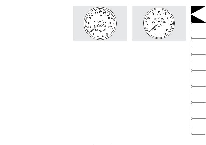
SPEEDOMETER fig. 18 |
REV. COUNTER fig. 18a |
|||||
|
It shows the car speed. |
The rev counter shows engine rpm. The |
|||||
|
needle pointed to the red area (danger) |
||||||
|
indicates excessive high engine speed. Do |
||||||
|
not drive for long periods with the needle |
||||||
|
in this area. |
IMPORTANT The electronic injection control system gradually shuts off the flow of fuel when the engine is “over-revving” resulting in a gradual loss of engine power.
When the engine is idling, the rev counter may indicate a gradual or sudden speed increase. This is normal as it takes place during normal operation, for example when activating the climate control system or the fan. In particular a slow change in the speed preserves the battery charge.
|
DASHBOARD AND CONTROLS |
|
|
SAFETY |
DEVICES |
|
CORRECT USE |
OF THE CAR |
|
WARNING |
LIGHTS AND MESSAGES |
|
IN AN |
EMERGENCY |
|
CAR |
MAINTENANCE |
|
TECHNICAL |
SPECIFICATIONS |
|
INDEX |
21
|
DASHBOARD |
AND CONTROLS |
|
SAFETY |
DEVICES |
|
CORRECT USE |
OF THE CAR |
|
WARNING LIGHTS AND |
MESSAGES |
|
IN AN |
EMERGENCY |
|
CAR |
MAINTENANCE |
|
TECHNICAL |
SPECIFICATIONS |
|
INDEX |
|
|
22 |
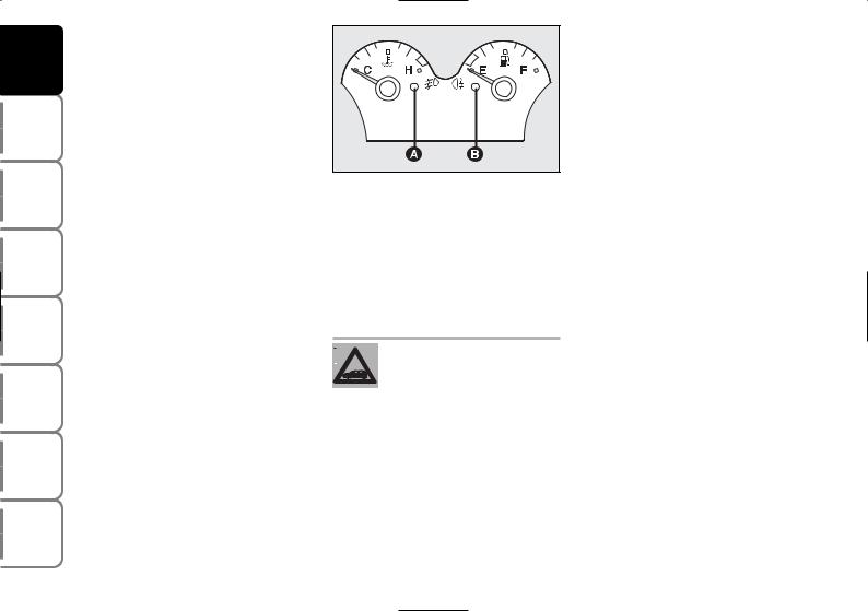
ENGINE COOLANT
TEMPERATURE GAUGE
This shows the temperature of the engine coolant fluid and begins working when the fluid temperature exceeds approx. 50°C.
Under normal conditions, the needle should move to different positions of the scale according to the conditions of use of the car.
C — Low engine coolant temperature.
H — High engine coolant temperature.
The turning on of the warning light A-fig. 19 (together with the message shown on the display) indicates that the coolant fluid temperature is too high; in this case, stop the engine and contact a Fiat Dealership.
If the needle reaches the red area, stop the engine immediately and contact a Fiat Dealership.
FUEL LEVEL GAUGE
This shows the amount of fuel left in the fuel tank.
The reserve warning light B- fig. 19 turns on to indicate that approx. 8 litres of fuel are left in the tank.
E — tank empty.
F — tank full (see the indications given in paragraph “At the filling station»).
Do not travel with the fuel tank almost empty: the gaps in fuel delivery could damage the catalyst.
IMPORTANT If the needle sets at E with warning light B flashing, it means that the system is malfunctioning. Contact a Fiat Dealership to have the system inspected.
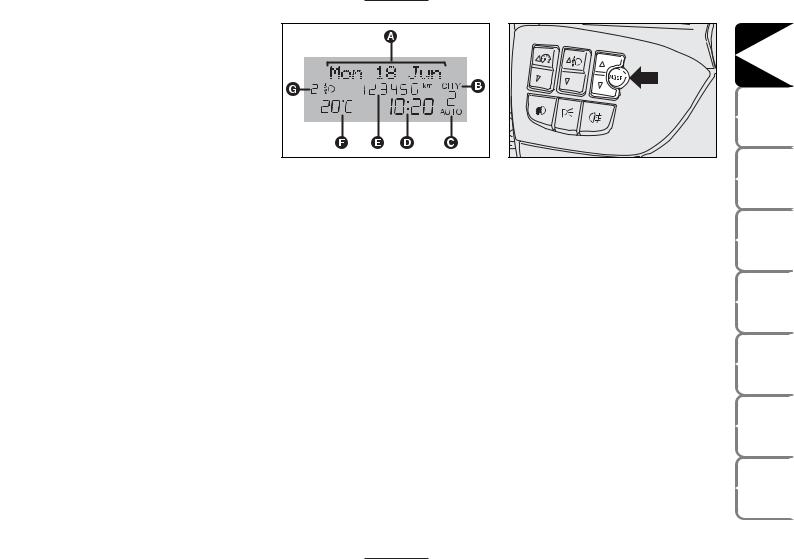
MULTIFUNCTION
DISPLAY
Your car is fitted with the multifunction display that shows all the useful information necessary when driving.
INFORMATION ON “STANDARD” SCREEN fig. 20
The standard screen shows the following indications:
A Date
BDualdrive electric power steering engagement, if any
CSelespeed mode (where provided) and engaged gear display
D Clock
E Odometer (covered km or miles)
F External temperature
G Headlight aiming position (only with dipped beam headlights on)
CONTROL BUTTONS fig. 21
ÕTo scroll the display and the related options upwards or to increase the value displayed.
MODE Brief press to open the menu and/or to move to next screen or to confirm the option required.
Long press to go back to the standard screen.
ÔTo scroll the display and the related options downwards or to decrease the value displayed.
Note Buttons Õand Ôactivate different functions according to the following situations:
–to scroll the menu options upwards and downwards;
–to increase or to decrease values during settings.
|
DASHBOARD AND CONTROLS |
|
|
SAFETY |
DEVICES |
|
CORRECT USE |
OF THE CAR |
|
WARNING |
LIGHTS AND MESSAGES |
|
IN AN |
EMERGENCY |
|
CAR |
MAINTENANCE |
|
TECHNICAL |
SPECIFICATIONS |
|
INDEX |
23

|
DASHBOARD |
AND CONTROLS |
|
SAFETY |
DEVICES |
|
CORRECT USE |
OF THE CAR |
|
WARNING LIGHTS AND |
MESSAGES |
|
IN AN |
EMERGENCY |
|
CAR |
MAINTENANCE |
|
TECHNICAL |
SPECIFICATIONS |
|
INDEX |
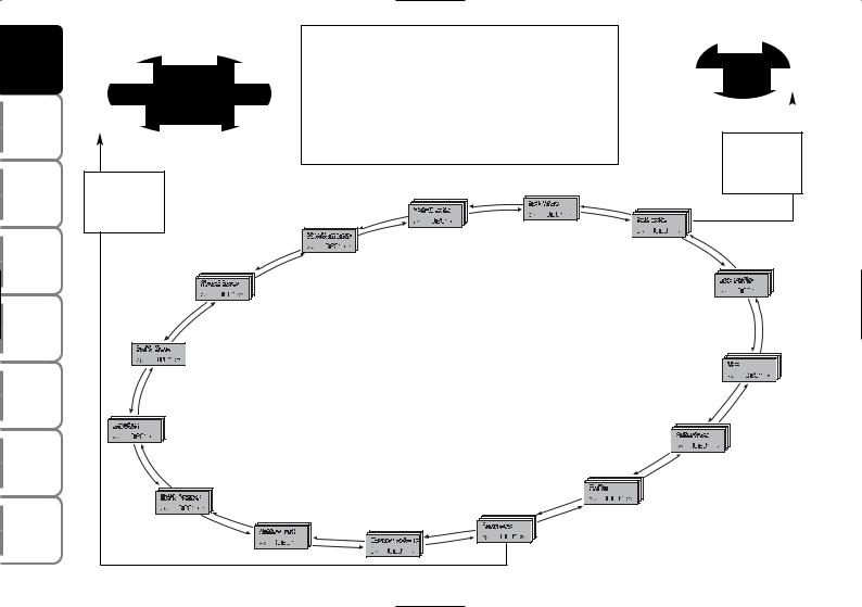
SETUP MENU fig. 22
The menu comprises a series of functions arranged in a “circular fashion” which can be selected through buttons Õ and Ô to access the different select operations and settings (setup) given below. For certain options (Set time and Units) there is a submenu.
The setup menu can be activated by pressing briefly button MODE.
Single presses on buttons Õ or Ô will scroll the setup menu options. Handling modes differ with each other according to the characteristic of the option selected.
Note If the car is equipped with Connect/Navigator, phone and audio info can be repeated on the multifunction display. For other set-up menu adjustments and/or settings, see the Connect/Navigator Supplement.
Selecting an option in the main menu without submenu:
–press briefly button MODE to select the menu option to set;
–press buttons Õ or Ô (by single presses) to select the new setting;
–press briefly button MODE to store the new setting and to go back to the previously selected menu option.
Selecting an option in the main menu with submenu:
–press briefly button MODE to display the first submenu option;
–press buttons Õ or Ô (by single presses) to scroll all submenu options;
–press briefly button MODE to select the displayed submenu option and to enter the relevant setup menu;
–press buttons Õ or Ô (by single presses) to select the new setting;
–press briefly button MODE to store the new setting and to go back to the previously selected submenu option.
24

Selecting “Set date” and “Set time”:
–briefly press button MODE to select the first value to change (e.g. hours /minutes or year / month / day);
–press buttons Õ or Ô (by single presses) to select the new setting;
–briefly press button MODE to store the new setting and to go to the next setup menu option, if this is the last one you will go back to the previously selected option of the main menu.
Press button MODE for long:
–to quit the submenu if you are at submenu option setting level;
–to quit the main menu if you are at submenu level;
–to quit the main menu if you are at main menu option setting level;
–to quit the set up menu if you are in the main menu;
–only settings stored yet by the user (and confirmed by pressing briefly button MODE) will be saved.
The setup menu displaying is timed; when quitting the menu due to timing expiry, only settings stored yet by the user (and confirmed by pressing briefly button MODE) will be saved.
|
DASHBOARD AND CONTROLS |
|
|
SAFETY |
DEVICES |
|
CORRECT USE |
OF THE CAR |
|
WARNING |
LIGHTS AND MESSAGES |
|
IN AN |
EMERGENCY |
|
CAR |
MAINTENANCE |
|
TECHNICAL |
SPECIFICATIONS |
|
INDEX |
25
|
DASHBOARD |
AND CONTROLS |
|
SAFETY |
DEVICES |
|
CORRECT USE |
OF THE CAR |
|
WARNING LIGHTS AND |
MESSAGES |
|
IN AN |
EMERGENCY |
|
CAR |
MAINTENANCE |
|
TECHNICAL |
SPECIFICATIONS |
|
INDEX |
|
Example: |
Briefly press button MODE to start surfing from the standard |
Day |
||||
|
Español |
||||||
|
screen. To surf the menu use buttons Õor Ô. For safety rea- |
||||||
|
Français |
Portuges |
sons, when the car is running, it is possible to access only the |
Year |
Month |
||
|
reduced menu (for setting the “Speed limit” and “Automatic |
||||||
|
Italiano |
Deutsch |
headlight sensor sensitivity adjustment” (where provided). |
||||
|
When the car is stationary access to the whole menu is en- |
||||||
|
English |
abled. On cars provided with Connect/Navigator many func- |
|||||
|
tions are displayed on the navigator display. |
MODE |
|||||
|
briefly press |
||||||
|
MODE |
button |
|||||
|
briefly press |
||||||
|
button |
||||||
|
TRIP B DATA |
SET TIME |
|||||
|
SET DATE |
||||||
|
HEADL. SENSOR |
||||||
|
SEE RADIO |
||||||
|
SPEED BEEP |
||||||
|
EXIT MENU |
||||||
|
KEY |
||||||
|
SERVICE |
AUTOCLOSE |
|||||
|
F0C2369g |
||||||
|
BELT BUZZER |
UNITS |
|||||
|
BUTTON VOL. |
LANGUAGE |
|||||
|
BUZZER VOLUME |
||||||
|
fig. 22 |
26

Speed limit (Speed Beep)
With this function it is possible to set the car speed limit (km/h or mph); when this limit is exceeded the driver is immediately alerted (see section “Warning lights and messages”).
To set the speed limit, proceed as follows:
–briefly press button MODE, the display will show wording (Speed Beep);
–press button Õ or Ô to select activation (On) or deactivation (Off) of the speed limit;
–if selecting (On), press button Õ or Ô to select the required speed limit and then press MODE to confirm.
Note The possible setting is between 30 and 250 km/h, or between 20 and 155 mph depending on the unit set previously (see paragraph “Distance unit (Distances)” described later. Every press on button Õ/Ô increases/decreases by 5 units. Keeping the button Õ/Ô pressed obtains the automatic fast increase or decrease. When you are near the required setting complete adjustment by single presses.
– briefly press button MODE to go back to the menu screen or press the button for long to go back to the standard screen without storing settings.
To abort the setting, proceed as follows:
–briefly press button MODE: (On) will flash on the display;
–press button Ô: (Off) will flash on the display;
–briefly press button MODE to go back to the menu screen or press the button for long to go back to the standard screen without storing settings.
Automatic headlight sensor sensitivity adjustment
(Headl. sensor) (where provided)
With this function it is possible to adjust the light sensor sensitivity according to 3 levels (level 1 = min. level, level 2 = average level, level 3 = max. level); the higher the sensitivity is, the lower is the external light intensity required to switch on the lights.
This operation can be performed also with the car moving.
To set the light level required, proceed as follows:
–briefly press button MODE, the previously set level will flash on the display;
–press button Õ or Ô to select the required level;
–briefly press button MODE to go back to the menu screen or press the button for long to go back to the standard screen without storing settings.
|
DASHBOARD AND CONTROLS |
|
|
SAFETY |
DEVICES |
|
CORRECT USE |
OF THE CAR |
|
WARNING |
LIGHTS AND MESSAGES |
|
IN AN |
EMERGENCY |
|
CAR |
MAINTENANCE |
|
TECHNICAL |
SPECIFICATIONS |
|
INDEX |
27

|
DASHBOARD |
AND CONTROLS |
|
SAFETY |
DEVICES |
|
CORRECT USE |
OF THE CAR |
|
WARNING LIGHTS AND |
MESSAGES |
|
IN AN |
EMERGENCY |
|
CAR |
MAINTENANCE |
|
TECHNICAL |
SPECIFICATIONS |
|
INDEX |
Trip B On/Off (TripB data)
Through this option it is possible to activate (On) or deactivate (Off) the Trip B (partial trip) (for further information see “Trip computer”).
For activation / deactivation, proceed as follows:
–briefly press button MODE: (On) or (Off) will flash on the display (according to previous setting);
–press button Õ or Ô for setting;
–briefly press button MODE to go back to the menu screen or press the button for long to go back to the standard screen without storing settings.
Setting the clock (Set time)
This function enables to set the clock through two submenus: “Time” and “Mode”.
To set the clock proceed as follows:
–briefly press button MODE, the display will show the two submenus “Time” and “Mode”;
–press button Õ or Ô to scroll the two submenus;
–select the required submenu and then press briefly MODE;
–if selecting “Time”: briefly press button MODE, “hours” will flash on the display;
–press button Õ or Ô for setting;
–press button MODE, “minutes” will flash on the display;
–press button Õ or Ô for setting.
–if selecting “Mode”: briefly press button MODE, “12h” or “24h” will flash on the display;
–press button Õor Ôto select “24h” or “12h”.
After setting, briefly press button MODE to go back to the submenu screen or press the button for long to go back to the main menu screen without storing settings.
– press again button MODE for long to go back to the standard screen or to the main menu according to the current menu level.
28

Setting the date (Set date)
This function enables to update the date (day – month – year).
To correct the date proceed as follows:
–briefly press button MODE: “year” will flash on the display;
–press button Õ or Ô for setting;
–briefly press button MODE: “month” will flash on the display;
–press button Õ or Ô for setting;
–briefly press button MODE: “day” will flash on the display;
–press button Õ or Ô for setting.
Note Every press on button Õ or Ô increases/decreases by 1 unit. Keeping the button pressed obtains automatic fast increase or decrease. When you are near the required setting complete adjustment by single presses.
– briefly press button MODE to go back to the menu screen or press the button for long to go back to the standard screen without storing settings.
Audio info repetition (See radio)
With this function the display repeats information relevant to the sound system.
–Radio: selected radio station frequency or RDS message;
–Audio CD/MP3 CD: CD and/or track number;
To activate (On) or to deactivate (Off) sound system info displaying proceed as follows:
–briefly press button MODE: (On) or (Off) will flash on the display (according to previous setting);
–press button Õ or Ô for setting;
–briefly press button MODE to go back to the menu screen or press the button for long to go back to the standard screen without storing settings.
Door opening mode (Key)
This function enables to select the required door opening mode:
–briefly press button MODE, the display will show the wording “Key”;
–press button Õ or Ô to select option “Open doors” or “Open all”;
–briefly press button MODE to go back to the menu screen or press the button for long to go back to the standard screen without storing settings.
–“Open doors”: press button Ëto open the doors (excluding the tailgate);
–“Open all”: press button Ëto open the doors and the tailgate.
|
DASHBOARD AND CONTROLS |
|
|
SAFETY |
DEVICES |
|
CORRECT USE |
OF THE CAR |
|
WARNING |
LIGHTS AND MESSAGES |
|
IN AN |
EMERGENCY |
|
CAR |
MAINTENANCE |
|
TECHNICAL |
SPECIFICATIONS |
|
INDEX |
29
![]()
|
DASHBOARD |
AND CONTROLS |
|
SAFETY |
DEVICES |
|
CORRECT USE |
OF THE CAR |
|
WARNING LIGHTS AND |
MESSAGES |
|
IN AN |
EMERGENCY |
|
CAR |
MAINTENANCE |
|
TECHNICAL |
SPECIFICATIONS |
|
INDEX |
|
Automatic central door locking |
Setting units (Units) |
If set unit is “km”, the display will show fu- |
|
|
when travelling (Autoclose) |
With this function it is possible to set the |
el consumption in km/l or l/100km. |
|
|
When activated (On), this function locks |
units through three submenus: “Dis- |
If set unit is “mi” the display will show fu- |
|
|
automatically the doors when the car |
tances”, “Consumption” and “Tempera- |
el consumption in “mpg”. |
|
|
speed exceeds 20 km/h. |
ture”. |
– press button Õ or Ô for setting; |
|
|
To activate (On) or to deactivate (Off) this |
To set the required unit proceed as fol- |
||
|
– if selecting “Temperature”: pressing but- |
|||
|
function proceed as follows: |
lows: |
||
|
ton MODE briefly, the display will show |
|||
|
– briefly press button MODE, the display |
|||
|
– briefly press button MODE, the display |
“°C” or “°F” (according to previous set- |
||
|
will show the wording “Travelling”. Word- |
will show the three submenus; |
ting); |
|
|
ings On or Off will flash (according to pre- |
– press button Õor Ôto scroll the three |
– press button Õ or Ô to select the re- |
|
|
vious setting); |
|||
|
submenus; |
quired level; |
||
|
– press button Õ or Ô for setting; |
|||
|
– select the required submenu and then |
|||
|
– briefly press button MODE to go back |
press briefly button MODE; |
||
|
to the menu screen or press the button |
– if selecting “Distances”: pressing button |
||
|
for long to go back to the standard screen |
|||
|
MODE briefly, the display will show “km” |
|||
|
without storing settings. |
|||
|
or “mi” (according to previous setting); |
|||
|
– press button Õ or Ô for setting; |
|||
|
– if selecting “Consumption”: pressing but- |
|||
|
ton MODE briefly, the display will show |
|||
|
“km/l ”, “l/100km” or “mpg” (according to |
|||
|
previous setting); |
30

After setting, briefly press button MODE to go back to the submenu screen or press the button for long to go back to the main menu screen without storing settings.
– press again button MODE for long to go back to the standard screen or to the main menu according to the current menu level.
Selecting the language (Language)
Display messages can be shown in different languages: Italian, French, Spanish, Portuguese, German, English.
To set the required language proceed as follows:
–briefly press button MODE: the previously set “language” will flash on the display;
–press button Õ or Ô for setting;
–briefly press button MODE to go back to the menu screen or press the button for long to go back to the standard screen without storing settings.
Setting the buzzer volume (Buzzer volume)
With this function the volume of the buzzer accompanying any failure/warning indication can be adjusted according to 8 levels.
To set the required the volume proceed as follows:
–briefly press button MODE: the previously set volume “level” will flash on the display;
–press button Õ or Ô for setting;
–briefly press button MODE to go back to the menu screen or press the button for long to go back to the standard screen without storing settings.
|
DASHBOARD AND CONTROLS |
|
|
SAFETY |
DEVICES |
|
CORRECT USE |
OF THE CAR |
|
WARNING |
LIGHTS AND MESSAGES |
|
IN AN |
EMERGENCY |
|
CAR |
MAINTENANCE |
|
TECHNICAL |
SPECIFICATIONS |
|
INDEX |
31

|
DASHBOARD |
AND CONTROLS |
|
SAFETY |
DEVICES |
|
CORRECT USE |
OF THE CAR |
|
WARNING LIGHTS AND |
MESSAGES |
|
IN AN |
EMERGENCY |
|
CAR |
MAINTENANCE |
|
TECHNICAL |
SPECIFICATIONS |
|
INDEX |
Adjusting the button volume (Button vol.)
With this function the volume of the roger-beep accompanying the activation of buttons MODE, Õ and Ô can be adjusted according to 8 levels.
To set the required the volume proceed as follows:
–briefly press button MODE: the previously set volume “level” will flash on the display;
–press button Õ or Ô for setting;
–briefly press button MODE to go back to the menu screen or press the button for long to go back to the standard screen without storing settings.
S.B.R. buzzer reactivation (Belt buzzer)
This function can be only displayed after Fiat Dealership has deactivated the S.B.R. system (see paragraph “S.B.R. system” in section “Safety devices”).
Scheduled Servicing (Service)
Through this function it is possible to display information connected to proper car servicing.
To display scheduled servicing info proceed as follows:
–briefly press button MODE: service in km or mi, according to previous setting, will be displayed (see paragraph “Distance unit”);
–press button Õ or Ô to select displaying in days;
–briefly press button MODE to go back to the menu screen or press the button for long to go back to the standard screen without storing settings.
32

Note The “Service Schedule” includes car maintenance every 30,000 km (or equivalent value in miles) or every year; this is shown automatically, with the ignition key at MAR, starting from 2,000 km (or equivalent value in miles) or 30 days from this deadline and it is shown again every 200 km (or equivalent value in miles) or every 3 days. Below 200 km servicing indications are displayed more frequently. Servicing indication will be displayed in km or mi according to previous setting. When a programmed maintenance interval (coupon) is near to come, turning the ignition key to MAR, the display will show the message “Service” followed by the number of km/mi or days to go before car servicing. “Scheduled servicing” message is displayed in km/mi or days according to the approaching service interval. Contact a Fiat Dealership to carry out any service operation provided by the “Service schedule” or “Annual inspection plan”, and to reset the display.
Exit Menu
This is the last function that closes the circular setting cycle listed in the initial menu screen.
Briefly press button MODE to go back to the standard screen without storing settings.
Press button Ôto return to the first menu option (Speed Beep).
Instrument panel, display and button lighting adjustment (Light rheostat)
With this function it is possible to adjust the lighting (dimming/brightening) of the instrument panel, sound system display, Connect/Navigator display, two-zone climate control display and steering wheel controls.
Press buttons Õ/Ô fig. 23 for light adjustment to carry out required light adjustment.
Return to standard screen is automatic or by pressing briefly button MODE.
|
DASHBOARD AND CONTROLS |
|
|
SAFETY |
DEVICES |
|
CORRECT USE |
OF THE CAR |
|
WARNING |
LIGHTS AND MESSAGES |
|
IN AN |
EMERGENCY |
|
CAR |
MAINTENANCE |
|
TECHNICAL |
SPECIFICATIONS |
|
INDEX |
|
|
33 |

|
DASHBOARD |
AND CONTROLS |
|
SAFETY |
DEVICES |
|
CORRECT USE |
OF THE CAR |
|
WARNING LIGHTS AND |
MESSAGES |
|
IN AN |
EMERGENCY |
|
CAR |
MAINTENANCE |
|
TECHNICAL |
SPECIFICATIONS |
|
INDEX |
TRIP COMPUTER
GENERAL
The “Trip computer” displays information (with ignition key at MAR), relating to the operating status of the car.
This function comprises the “General trip” concerning the “complete mission” of the car (journey) and “Trip B”, concerning the partial mission of the car; this latter function is “contained” (as shown in fig. 25) within the complete mission. Both functions are resettable (reset — start of new mission).
“General Trip” displays the figures relating to:
–Range
–Trip distance
–Average consumption
–Instant consumption
–Average speed
–Trip time (driving time).
“Trip B” displays the figures relating to:
–Trip distance B
–Average consumption B
–Average speed B
–Trip time B (driving time).
Note “Trip B” function can be excluded (see paragraph “Trip B On/Off”). “Range” and “Instant consumption” cannot be reset.
Values displayed
Range
This value shows the distance in km (or mi) that the car can still cover before needing fuel, assuming that driving conditions are kept unvaried. The display will show “—-” if the range value is below 50 km (or 30 mi).
Trip distance
This value shows the distance covered from the start of the new mission.
Average consumption
This value shows the average consumption from the start of the new mission.
Instant consumption
This value shows instant fuel consumption (this value is updated second by second). If parking the car with engine on, the display will show “—-”.
Average speed
This value shows the car average speed as a function of the overall time elapsed since the start of the new mission.
34

Trip time
This value shows the time elapsed since the start of the new mission.
IMPORTANT Lacking information, Trip computer values are displayed with “—-”. When normal operating condition is reset, calculation of different units will restart regularly. Values displayed before the failure will not be reset.
TRIP button fig. 24
The TRIP button, set on right steering column stalk, shall be used (with ignition key at MAR), to display and to reset the previously described values to start a new mission:
–short push to display the different values;
–long push to reset and then start a new mission.
New mission
New mission starts after:
–“manual” resetting by the user, by pressing the relevant button;
–“automatic” resetting, when the “trip distance” reaches 4999,9 km or when the “trip time” reaches 99.59 (99 hours and 59 minutes);
–after disconnecting/reconnecting the battery.
|
DASHBOARD AND CONTROLS |
|
|
SAFETY |
DEVICES |
|
CORRECT USE |
OF THE CAR |
|
WARNING |
LIGHTS AND MESSAGES |
|
IN AN |
EMERGENCY |
|
CAR |
MAINTENANCE |
|
TECHNICAL |
SPECIFICATIONS |
|
INDEX |
|
|
35 |

|
DASHBOARD |
AND CONTROLS |
|
SAFETY |
DEVICES |
|
CORRECT USE |
OF THE CAR |
|
WARNING LIGHTS AND |
MESSAGES |
|
IN AN |
EMERGENCY |
|
CAR |
MAINTENANCE |
|
TECHNICAL |
SPECIFICATIONS |
|
INDEX |
IMPORTANT The reset operation in the presence of the screens concerning the “General Trip” makes it possible to reset also the “Trip B”. The reset operation in the presence of the screens concerning only the “Trip B” makes it possible to reset only the information associated with this function.
Start of journey procedure
With ignition key at MAR, press and keep TRIP button pressed for over 2 seconds to reset.
Reset GENERAL TRIP
End of complete mission Start of new mission
Reset GENERAL TRIP
End of complete mission Start of new mission
|
˙ |
GENERAL TRIP |
˙ |
|||||
|
˙ |
Reset TRIP B |
˙ |
|||||
|
˙˙ |
|||||||
|
TRIP B |
|||||||
|
TRIP B |
Reset TRIP B |
||||||
|
Reset TRIP B |
TRIP B |
||||||
|
End of partial mission |
|||||||
|
Start of new partial mission |
˙ |
˙ |
|||||
|
End of partial mission |
|||||||
|
Start of new |
|||||||
|
partial mission |
|||||||
|
End of partial mission |
Reset TRIP B |
||||||
|
Start of new |
End of partial mission |
||||||
|
partial mission |
Start of new |
partial mission
fig. 25
36

SEATS
FRONT SEATS fig. 26
Moving the seat backwards or forwards
Lift the lever A (on the internal side of the seat) and push the seat forwards or backwards: in driving position the arms should rest on the rim of the steering wheel.
Seat height adjustment (where provided)
Move the lever B upwards or downwards to achieve the required height.
IMPORTANT Adjustment must be carried out only seated in the driver’s seat.
Back rest angle adjustment
Turn the knob C.
Lumbar adjustment (where provided)
To adjust, turn the knob D.
Tilting the back rest (3-door versions)
To gain access to the rear seats, pull the handle E upwards, the back rest folds and the seat is free to run forwards. When resetting the back rest, the seat returns to its original position (mechanical memory).
Only make adjustments when the car is stationary.
Fabric upholstery of your car is purpose-made to withstand common wear resulting from normal use of the car. It is
however absolutely necessary to prevent hard and/or prolonged scratching/scraping caused by clothing accessories like metallic buckles, studs, “Velcro” fixings, etc. that stressing locally the fabric could break yarns and damage the upholstery as a consequence.
Once you have released the lever, check that the seat is firmly locked in the runners by trying to move it back and
forth. Failure to lock the seat in place could result in the seat moving suddenly and the driver losing control of the car.
|
DASHBOARD AND CONTROLS |
|
|
SAFETY |
DEVICES |
|
CORRECT USE |
OF THE CAR |
|
WARNING |
LIGHTS AND MESSAGES |
|
IN AN |
EMERGENCY |
|
CAR |
MAINTENANCE |
|
TECHNICAL |
SPECIFICATIONS |
|
INDEX |
37

|
DASHBOARD |
AND CONTROLS |
|
SAFETY |
DEVICES |
|
CORRECT USE |
OF THE CAR |
|
WARNING LIGHTS AND |
MESSAGES |
|
IN AN |
EMERGENCY |
|
CAR |
MAINTENANCE |
|
TECHNICAL |
SPECIFICATIONS |
|
INDEX |
|
|
38 |
Seat warming
(where provided) fig. 27
With ignition key at MAR, press button Cto switch the seat warming on/off. The led on the button will light up when the function is on.
Front passenger’s seat
“table” tilting (where provided)
To tilt the seat, use lever A-fig. 28 and fold the back rest at the same time.
To reset it to normal position, lift the back rest in the direction opposed to the arrow until hearing the coupling click.
EASY ENTRY (3-door versions)
This function, operating regardless of the ignition key position, facilitates access to rear seats.
To access the rear seats lift handle A-fig. 29 and move the seat back forwards B: the seat automatically slides forward.

When the front seat back is returned to its normal position, the seat returns to its original position.
If, when returning to the original position, it finds an obstacle (e.g.: rear passenger’s knees) it stops; then moves forwards of few centimetres and then it locks.
REAR SLIDING SEATS (where provided)
Back rest angle adjustment
Lift handle A-fig. 30 and guide the back rest adjusting it in one of the six available positions.
Moving the seat backwards or forwards
Lift lever B taking it in the middle and move the seat backwards or forwards; the two sides can be adjusted individually.
Fabric upholstery of your car is purpose-made to withstand common wear resulting from normal use of the car. It is
however absolutely necessary to prevent hard and/or prolonged scratching/scraping caused by clothing accessories like metallic buckles, studs, “Velcro” fixings, etc. that stressing locally the fabric could break yarns and damage the upholstery as a consequence.
|
DASHBOARD AND CONTROLS |
|
|
SAFETY |
DEVICES |
|
CORRECT USE |
OF THE CAR |
|
WARNING |
LIGHTS AND MESSAGES |
|
IN AN |
EMERGENCY |
|
CAR |
MAINTENANCE |
|
TECHNICAL |
SPECIFICATIONS |
|
INDEX |
|
|
39 |
![]()
|
DASHBOARD |
AND CONTROLS |
|||
|
SAFETY |
DEVICES |
|||
|
CORRECT USE |
OF THE CAR |
fig. 31 |
F0C0314m |
|
|
The space obtained between the rear seat |
||||
|
back and the baggage compartment can be |
||||
|
WARNING LIGHTS AND |
MESSAGES |
covered with proper boot covers B- |
||
|
fig. 31 (left-hand side) and D (right-hand |
||||
|
side). |
||||
|
To do this, take tongues A-fig. 31and C |
||
|
ANIN |
EMERGENCY |
and leading them delicately, hook covers |
|
B-fig. 31 and D to the relevant fixings E- |
||
|
fig. 32 located on the back of the rear seat |
||
|
backs. |
||
|
CAR |
MAINTENANCE |
|
|
TECHNICAL |
SPECIFICATIONS |
|
|
INDEX |
To guarantee proper seat belt fastening when travelling, the seat back shall be adjusted in 4th position fig. 33
WARNING
Only make adjustments when the car is stationary.
WARNING
Once you have released the lever, check that the seat is firmly locked in the runners by trying
to move it back and forth. Failure to lock the seat in place could result in the seat moving suddenly and the driver losing control of the car.
WARNING
For maximum safety, keep the back of your seat upright, lean back into it and make sure
the seat belt fits closely across your chest and hips.
40

|
HEAD RESTRAINTS |
|
|
FRONT |
|
|
Head restraints are adjustable in height |
|
|
and they lock automatically in the required |
|
|
position. |
|
|
to raise: raise the head restraint until |
|
|
hearing the locking click. |
|
|
fig. 34 |
F0C0123m |
|
to lower: press button A-fig. 34 and |
|
|
lower the head restraint. |
WARNING |
Remember that the head restraints should be adjusted to support the back of your head and
not your neck. Only in this position do they exert their protective action.
WARNING
To optimise head restraint protective action, adjust the seat back upright and keep your head
as close as possible to the head restraint.
REAR
Rear seats are fitted with three head restraints.
To lift out head restraint: take it completely out from the seat back (position of use) until hearing a click.
To bring it back to the original position (non-use position): press button A- fig. 35 and lower the head restraint down into its seat.
IMPORTANT Rear seat passengers shall always set the head restraints in the position of use.
|
DASHBOARD AND CONTROLS |
|
|
SAFETY |
DEVICES |
|
CORRECT USE |
OF THE CAR |
|
WARNING |
LIGHTS AND MESSAGES |
|
IN AN |
EMERGENCY |
|
CAR |
MAINTENANCE |
|
TECHNICAL |
SPECIFICATIONS |
|
INDEX |
|
|
41 |

|
DASHBOARD |
AND CONTROLS |
|
SAFETY |
DEVICES |
|
CORRECT USE |
OF THE CAR |
|
WARNING LIGHTS AND |
MESSAGES |
|
IN AN |
EMERGENCY |
|
CAR |
MAINTENANCE |
|
TECHNICAL |
SPECIFICATIONS |
|
INDEX |
STEERING WHEEL
The driver can adjust the steering wheel position both axially and in height.
Release the lever A-fig. 36 pulling it towards the steering wheel, then adjust it in the most suitable position and lock it pushing the lever A fully forwards.
WARNING
It is absolutely forbidden to carry out whatever aftermarket operation involving steering
system or steering column modifications (e.g.: installation of anti-theft device) that could badly affect performance and safety, cause the lapse of warranty and also result in noncompliance of the car with homologation requirements.
WARNING
Any adjustment of the steering wheel position must be carried out only with the car station-
ary and the engine turned off.
42

REARVIEW MIRRORS
DRIVING MIRROR
The mirror is fitted with a safety device that causes it to be released in the event of a violent crash.
It can be moved using the lever A-fig. 37 to two different positions: normal or antiglare.
DOOR MIRRORS
Manual adjustment
When required (for example when the mirror causes difficulty in narrow spaces) it is possible to fold the mirror moving it from position A-fig. 38 to position B.
|
fig. 37 |
F0C0040m |
|
fig. 38 |
F0C00144m |
Electrical adjustment
Proceed as follows:
use switch A-fig. 39 to select the mirror required (left or right);
to adjust the mirror move the joystick B in the four directions.
|
When driving the mirrors shall |
As the driver’s door mirror is |
|
always be in position A-fig. 38. |
curved, it may slightly alter the |
|
perception of distance. |
|
DASHBOARD AND CONTROLS |
|
|
SAFETY |
DEVICES |
|
CORRECT USE |
OF THE CAR |
|
WARNING |
LIGHTS AND MESSAGES |
|
IN AN |
EMERGENCY |
|
CAR |
MAINTENANCE |
|
TECHNICAL |
SPECIFICATIONS |
|
INDEX |
43

|
DASHBOARD |
AND CONTROLS |
|
SAFETY |
DEVICES |
|
CORRECT USE |
OF THE CAR |
|
WARNING LIGHTS AND |
MESSAGES |
|
IN AN |
EMERGENCY |
|
CAR |
MAINTENANCE |
|
TECHNICAL |
SPECIFICATIONS |
|
INDEX |
HEATING/CLIMATE CONTROL SYSTEM
F0C0002m
fig. 40
1. Upper fixed vent for defrosting or demisting windscreen — 2. Centre adjustable vent —3. Fixed vents for defrosting or demisting side windows — 4. Side adjustable and swivel vents — 5. Lower vents — 6. Rear adjustable and swivel outlet — 7. Rear feet area fixed vents.
44

|
fig. 41 |
F0C0064m |
fig. 42 |
F0C0031m |
fig. 43 |
F0C0030m |
SIDE SWIVEL OUTLETS AND VENTS fig. 41
A — Fixed vent for side windows.
B — Air flow adjusting control:
ç = completely closed
O = completely open.
C — Control for directing air flow (up/down, right/left).
CENTRAL VENTS fig. 42
A — Controls for directing air flow (up/down, right/left).
B — Air flow adjusting controls:
ç = completely closed
O = completely open.
REAR VENT fig. 43 (where provided)
A — Controls for directing air flow (up/down, right/left).
B — Air flow adjusting control:
ç = completely closed
O = completely open.
Certain versions feature an oddment compartment instead of the rear vent.
|
DASHBOARD AND CONTROLS |
|
|
SAFETY |
DEVICES |
|
CORRECT USE |
OF THE CAR |
|
WARNING |
LIGHTS AND MESSAGES |
|
IN AN |
EMERGENCY |
|
CAR |
MAINTENANCE |
|
TECHNICAL |
SPECIFICATIONS |
|
INDEX |
|
|
45 |

|
DASHBOARD |
AND CONTROLS |
|
SAFETY |
DEVICES |
|
CORRECT USE |
OF THE CAR |
|
WARNING LIGHTS AND |
MESSAGES |
|
IN AN |
EMERGENCY |
|
CAR |
MAINTENANCE |
|
TECHNICAL |
SPECIFICATIONS |
|
INDEX |
HEATING AND
VENTILATION
CONTROLS
A: Air temperature knob (mixing hot and cold air)
B: Heated rear window on/off button
C: Fan knob
D: Air recirculation on/off button
E: Air distribution knob.
fig. 44
WARMING THE PASSENGER
COMPARTMENT
Proceed as follows:
knob pointer A in the red section;
knob pointer C on required speed;
turn the knob E to:
F0C0380m
≤to warm the feet and at the same time demist the windscreen
μto warm the feet and keep the face cool (“bilevel” function)
wto warm the feet of the passengers in the front and rear seats
air recirculation off (button led T off).
46

FRONT WINDOW
FAST DEMISTING/DEFROSTING
Proceed as follows:
rotate completely (pointer on —) knob A to the right;
turn knob C to —;
turn knob E to —;
air recirculation off (button led T off).
After demisting/defrosting use common controls to maintain the optimum conditions of visibility and comfort.
Window demisting
In the event of considerable outside moisture and/or rain and/or considerable differences in temperature inside and outside the passenger compartment, perform the following preventive demisting procedure:
air recirculation off (button led T off);
turn knob A to red section;
turn knob C to 2nd speed;
turn knob E to —or to ≤if the windows do not demist.
HEATED REAR WINDOW AND DOOR MIRROR DEMISTING/DEFROSTING
Pressing button (turns on this function which is shown by the turning on of the led on the button (.
This function is timed and switches off automatically after 20 minutes. To cut out this function press again button (.
IMPORTANT Do not apply stickers on the inside of the rear window over the heating filaments to avoid damage that might cause it to stop working properly.
FAN SPEED ADJUSTMENT
To ventilate the passenger’s compartment properly, proceed as follows:
Central and side vents: completely open;
Knob pointer A on blue section;
knob pointer C on required speed;
Knob pointer E to ¥;
air recirculation off (button led T off).
RECIRCULATION
Pressing button T turns on this function which is shown by the turning on of the led on the button. This function is particularly useful when the outside air is heavily polluted (in a traffic jam, tunnel, etc.). However, it is better not to use it for long periods, especially if there are several people in the car.
IMPORTANT The inside air recirculation system makes it possible to reach the required “heating” or “cooling” conditions faster. Do not use the air recirculation function on rainy/cold days as it would considerably increase the possibility of the windows misting inside.
|
DASHBOARD AND CONTROLS |
|
|
SAFETY |
DEVICES |
|
CORRECT USE |
OF THE CAR |
|
WARNING |
LIGHTS AND MESSAGES |
|
IN AN |
EMERGENCY |
|
CAR |
MAINTENANCE |
|
TECHNICAL |
SPECIFICATIONS |
|
INDEX |
47

|
DASHBOARD |
AND CONTROLS |
|
SAFETY |
DEVICES |
|
CORRECT USE |
OF THE CAR |
|
WARNING LIGHTS AND |
MESSAGES |
|
IN AN |
EMERGENCY |
|
CAR |
MAINTENANCE |
|
TECHNICAL |
SPECIFICATIONS |
|
INDEX |
MANUAL CLIMATE CONTROL SYSTEM (where provided)
CONTROLS
A: Air temperature knob (mixing hot and cold air)
B: Heated rear window on/off button
C: Fan knob
D: Compressor on/off switch
E: Air recirculation on/off button
F: Air distribution knob.
fig. 45
WARMING THE PASSENGER
COMPARTMENT
Proceed as follows:
knob pointer A in the red section;
knob pointer C on required speed;
turn knob F to:
F0C0372m
≤to warm the feet and at the same time demist the windscreen
μto warm the feet and keep the face cool (“bilevel” function)
wto warm the feet of the front and rear passengers.
air recirculation off (button led T off).
48

FRONT WINDOW
FAST DEMISTING/DEFROSTING
Proceed as follows:
press button ;
rotate completely (pointer on —) knob A to the right;
turn knob C to —;
turn knob F to —;
air recirculation off (button led T off).
After demisting/defrosting use common controls to maintain the optimum conditions of visibility and comfort.
Window demisting
In the event of considerable outside moisture and/or rain and/or considerable differences in temperature inside and outside the passenger compartment, perform the following preventive demisting procedure:
press button ;
air recirculation off (button led T off);
turn knob A to red section;
turn knob C to 2nd speed;
turn knob F to —or to ≤if the windows do not demist.
Climate control system is very useful to speed up demisting since it dehumidifies the air. Set controls to demisting function and switch on the climate control system by pressing button .
HEATED REAR WINDOW AND DOOR MIRROR DEMISTING/DEFROSTING
Pressing button (turns on this function which is shown by the turning on of the led on the button (.
This function is timed and switches off automatically after 20 minutes. To cut out this function press again button (.
IMPORTANT Do not apply stickers on the inside of the rear window over the heating filaments to avoid damage that might cause it to stop working properly.
FAN SPEED ADJUSTMENT
To ventilate the passenger’s compartment properly, proceed as follows:
Central and side vents: completely open;
Knob pointer A on blue section;
knob pointer C on required speed;
Knob pointer F to ¥;
air recirculation off (button led T off).
|
DASHBOARD AND CONTROLS |
|
|
SAFETY |
DEVICES |
|
CORRECT USE |
OF THE CAR |
|
WARNING |
LIGHTS AND MESSAGES |
|
IN AN |
EMERGENCY |
|
CAR |
MAINTENANCE |
|
TECHNICAL |
SPECIFICATIONS |
|
INDEX |
49