| Тема | Автор: | Статистика | |
|---|---|---|---|
|
Прикреплено Подробный мануал по ПТФ на пятерку
|
|
||
|
Прикреплено Manual Prelude V
|
|
||
|
Прикреплено Самодиагностика — Коды ошибок
|
|
||
|
Электросхемы Prelude 5
|
|
||
|
|
Каталоги запчастей
|
|
|
|
я купил prelude…драмма в пяти частях
|
|
||
|
Мануал по ремонту 4WS с русским переводом
|
|
||
|
Регламент технического обслуживания Prelude V
|
|
||
|
Геометрия кузовов
|
|
||
|
Модификации Prelude 5th Gen
|
|
||
|
Кузова и комплектации Prelude
|
|
||
|
Manual Prelude IV
|
|
||
|
|
Технические регламенты Prelude IV
|
|
|
|
|
Общая информация о прелюдах (статья SHR)
|
|

Подборка руководств на английском языке по техническому обслуживанию и ремонту Honda Prelude 1983-1987 годов выпуска.
- Автор: —
- Издательство: Honda Motor Co., Ltd.
- Год издания: 1983/1984/1985/1986
- Страниц: 705/137/518/79
- Формат: PDF
- Размер: 73,0 Mb
Подборка руководств на английском языке по техническому обслуживанию и ремонту Honda Prelude 1987-1991 годов выпуска.
- Автор: —
- Издательство: Honda Motor Co., Ltd.
- Год издания: —
- Страниц: —
- Формат: PDF
- Размер: 55,5 Mb

Подборка руководств на английском языке по техническому обслуживанию и ремонту Honda Prelude 1992-1996 годов выпуска.
- Автор: —
- Издательство: Honda Motor Co., Ltd.
- Год издания: —
- Страниц: —
- Формат: PDF
- Размер: 117,9 Mb

Руководство на английском языке по техническому обслуживанию и ремонту Honda Prelude 1997-1999 годов выпуска.
- Автор: —
- Издательство: Honda Motor Co., Ltd.
- Год издания: —
- Страниц: —
- Формат: PDF
- Размер: 373,4 Mb

Руководство по эксплуатации, техническому обслуживанию и ремонту Honda Accord и Honda Prelude 1984-1991 годов выпуска с бензиновыми двигателями.
- Автор: —
- Издательство: РВС
- Год издания: 1998
- Страниц: 319 (отсутствуют стр. 240-366)
- Формат: PDF
- Размер: 60,0 Mb

Supplemental Restraint System
2
General Information
3
Chassis & Paint Codes
4
Vehicle Identification Number
4
Engine Number
4
Transmission Number
4
Vehicle/Engine/Transmission Number
5
Identification Number Locations
10
Warning/Caution Label Locations
11
Under-Hood Emissions Control Label
16
Emission Group Identification (1997 Model)
16
Engine and Evaporative Families
16
Emission Group Identification (1998 Model)
17
Emission Group Identification (1999 Model)
18
Lift and Safety Stands
19
Floor Jack
20
Towing
21
Service Precautions
22
Parts Marking Locations
22
Label Locations
22
Specifications
23
Standard and Service Limits
24
Design Specifications
35
Body Specifications
38
Maintenance
39
Lubrication Points
40
Maintenance Schedule for 1997 Model
44
Severe Conditions
44
Maintenance Schedule for 1998 Model
46
Normal Conditions
46
Maintenance Schedule for 1999 Model
50
Engine Electrical
55
Special Tools
56
Starting System
57
Component Location Index
57
Circuit Diagram
58
Starter Test
59
Check Starter Engagement
59
Starter Solenoid Test
60
Check for Wear and Damage
60
Check Cranking Voltage and Current Draw
60
Check Cranking Rpm
60
Starter Replacement
61
Starter Overhaul
62
Armature Inspection and Test
63
Starter Brush Holder Test
65
Starter Brush Inspection
65
Overrunning Clutch Inspection
66
Starter Reassembly
66
Performance Test
67
Ignition System Component Location Index
68
Ignition Timing Control System
68
Ignition System Circuit Diagram
69
Ignition Timing Inspection
70
Distributor Replacement
71
Distributor Overhaul
72
Ignition Control Module (ICM) Input Test
73
Ignition Wire Inspection and Test
74
Ignition Coil Test
74
Spark Plug Inspection
75
Charging System Component Location Index
76
Charging System Circuit Diagram
77
Charging System Troubleshooting
78
Alternator Replacement
83
Alternator Overhaul
84
Rectifier Test
85
Alternator Brush Inspection
85
Rotor Slip Ring Test
86
Stator Test
86
A/C Compressor (Alternator) Belt Inspection and Adjustment
87
Cruise Control Component Location Index
88
Cruise Control Circuit Diagram
89
Cruise Control Control Unit Input Test
90
Main Switch Test/Replacement
92
Set/Resume Switch Test/Replacement
92
Actuator Test
94
Actuator Replacement
95
Actuator Cable Adjustment
95
Clutch Switch Test
96
Brake Switch Test
96
Actuator Solenoid Test
97
Actuator Disassembly
98
Engine
99
Engine Removal/Installation
101
Engine Removal
102
Engine Installation
110
Cylinder Head/Valve Train
115
Cylinder Head/Valve Train Special Tools
116
VTEC Control System Troubleshooting Flowchart
117
VTEC Solenoid Valve Inspection
120
VTEC Rocker Arms Manual Inspection
121
VTEC Rocker Arms Inspection Using Special Tools
121
Valve Clearance Adjustment
123
Crankshaft Pulley and Pulley Bolt Replacement
125
Timing Belt and Timing Balancer Belt Illustrated Index
126
Timing Belt Inspection
127
Timing Balancer Belt Inspection
127
Timing Belt and Timing Balancer Belt Removal
128
Timing Belt and Timing Balancer Belt Installation
130
CKP/TDC Sensors Replacement
135
Cylinder Head Illustrated Index
136
Cylinder Head Removal
138
Rocker Arms and Shafts Removal
142
Rocker Arms and Shafts Disassembly/Reassembly
144
Rocker Arms and Shafts Clearance Inspection
145
Rocker Arms Inspection
146
Lost Motion Assemblies Inspection
146
Camshafts Inspection
147
Valves, Valve Springs and Valve Seals Removal
149
Valve Seats Reconditioning
151
Cylinder Head Warpage
152
Valve Guides Valve Movement
152
Valve Guides Replacement
153
Valve Guides Reaming
154
Valves, Valve Springs and Valve Seals Installation
155
Rocker Arms Installation
156
Cylinder Head Installation
157
Engine Block
161
Engine Block Special Tools
162
Engine Block Illustrated Index
163
Flywheel and Drive Plate Replacement
167
Connecting Rod and Crankshaft End Play
167
Main Bearings Clearance
168
Main Bearings Selection
169
Connecting Rod Bearings Clearance
170
Connecting Rod Bearings Selection
171
Crankshaft, Balancer Shafts and Pistons Removal
172
Crankshaft Inspection
175
Crankshaft Alignment
175
Crankshaft Out-Of-Round and Taper
175
Pistons Inspections
176
Cylinder Block Inspection
177
Cylinder Block Bore Honing
178
Piston Pins Removal
179
Piston Pins Inspection
180
Connecting Rods Selection
181
Piston Pins Installation
181
Piston Rings End Gap
182
Piston Rings Replacement
183
Piston Rings Rin-To-Groove Clearance
183
Piston Rings Alignment
184
Crankshaft Oil Seal Installation
185
Piston Installation
185
Crankshaft and Balancer Shafts Installation
186
Crankshaft and Balancer Shaft Oil Seals Installation
191
Balancer Shafts Inspection
192
Engine Lubrication
195
Engine Lubrication Special Tools
196
Engine Lubrication Illustrated Index
197
Engine Oil Inspection
200
Engine Oil Replacement
200
Oil Filter Replacement
201
Oil Pressure Switch Testing
204
Oil Pressure Testing
204
Oil Jet Inspection
206
Oil Pump Overhaul
207
Oil Pump Removal/Inspection/Installation
208
Intake Manifold/Exhaust System
213
Intake Manifold Replacement
214
Exhaust Manifold Replacement
215
Exhaust Pipe and Muffler Replacement
216
Cooling
219
Radiator Illustrated Index
220
Radiator Replacement
222
Engine Coolant Refilling and Bleeding
223
Radiator Cap Testing
224
Radiator Testing
224
Thermostat Replacement
225
Thermostat Testing
226
Water Pump Illustrated Index
227
Water Pump Inspection
228
Water Pump Replacement
228
Fan Control Component Location Index
229
Fan Controls Circuit Diagram
230
Fan Motor Testing
231
Radiator Fan Switch Testing
231
Engine Coolant Temperature Gauge Testing
232
Coolant Temperature Sending Unit Testing
232
Fuel and Emissions
233
Fuel and Emissions Special Tools
234
Fuel and Emissions Component Locations
235
Fuel and Emissions System Description
239
Vacuum Connections
239
Electrical Connections
245
System Connectors (Engine Compartment)
256
System Connectors (Dash and Floor)
262
Troubleshooting Procedures
268
How to Use the Backprobe Sets
271
Engine Control Module Terminal Arrangement
275
Diagnostic Trouble Code (DTC) Chart
278
How to Read Flowcharts
283
PGM-FI System Description
284
PGM-FI System Engine Control Module (ECM)
286
PGM-FI System Manifold Absolute Pressure (MAP) Sensor
290
PGM-FI System Intake Air Temperature (IAT) Sensor
294
Engine Coolant Temperature (ECT) Sensor
297
PGM-FI System Throttle Position (TP) Sensor
300
Primary Heated Oxygen Sensor (Primary H02S)(Sensor 1)
304
Secondary Heated Oxygen Sensor (Primary H02S)(Sensor 2)
308
Heated Oxygen Sensor (H02S) Heater
311
Fuel Supply System
313
Misfire Detected in One Cylinder
315
Random Misfire
318
Knock Sensor (KS)
319
Crankshaft Position/Top Dead Center (CKP/TDC) Sensor
320
Vehicle Speed Sensor (VSS)
322
Barometric Pressure (BARO) Sensor
323
Electrical Load Detector (ELD)
324
Cylinder Position (CYP) Sensor
327
ECM Internal Circuit
329
A/T Signal (SEFA/SEAF)
330
H02S Replacement
331
Idle Control System Description
332
Idle Control System
333
Idle Air Control (IAC) Valve
335
Air Conditioning Signal
337
Alternator (ALT) FR Signal
339
Idle Control System Starter Switch Signal
340
Power Steering Pressure (PSP) Switch Signal
341
Brake Switch Signal
343
Automatic Transaxle (A/T) Gear Position Signal
344
Fast Idle Thermo Valve
346
Idle Speed Setting
347
Fuel Lines
348
Fuel Tube/Quick-Connect Fittings
352
Fuel Supply System Description
355
Fuel Pressure
355
Fuel Injectors
356
Fuel Pressure Regulator
358
Fuel Filter
359
Fuel Pump Testing
360
Fuel Pump Replacement
360
Fuel Gauge Testing
361
Fuel Gauge Sending Unit Testing
362
Low Fuel Indicator System
363
Indicator Light Testing
363
PGM-FI Main Relay Description
364
PGM-FI Main Relay Testing
364
PGM-FI Main Relay Troubleshooting
365
Fuel Tank
367
Intake Air System Description
369
Air Cleaner Element Replacement
370
Throttle Cable Inspection/Adjustment
371
Throttle Cable Installation
371
Throttle Body Description
372
Throttle Body Inspection
372
Throttle Body Removal
373
Throttle Body Disassembly
373
Intake Air System
374
Intake Control System Description
374
Intake Air Bypass (IAB) Control System Description
378
Emission Control System Description
382
Tailpipe Emission Inspection
382
Three Way Catalytic Converter (TWC) Description
382
Three Way Catalytic Converter (TWC) Inspection
382
Three Way Catalytic Converter (TWC) Troubleshooting Flowchart
383
Exhaust Gas Recirculation (EGR) System Description
384
Positive Crankcase Ventilation (PCV) System Description
392
Positive Crankcase Ventilation (PCV) System Inspection
392
Evaporative Emission (EVAP) Controls Description
393
ORVR Vent Shut Valve Test
426
Float Test
426
Valve Test
426
ORVR Vent Shut Valve Replacement
427
Transaxle
429
Clutch
431
Clutch Special Tools
432
Clutch Illustrated Index
433
Clutch Pedal Adjustment
434
Clutch Master Cylinder Removal/Installation
435
Slave Cylinder Removal/Installation
436
Pressure Plate Removal/Inspection
437
Clutch Disc Removal/Inspection
438
Flywheel Inspection/Replacement
439
Clutch Disc, Pressure Plate Installation
440
Release Bearing Removal/Inspection
441
Release Bearing Installation
441
Manual Transmission
443
Manual Transmission Special Tools
444
Transmission Oil
445
Back-Up Light Switch Test/Replacement
445
Transmission Assembly Removal
446
Transmission Assembly Installation
452
Gearshift Mechanism Overhaul
455
Gearshift Mechanism Illustrated Index
456
Shift Arm Assembly Index
458
Shift Arm Disassembly/Reassembly
459
Transmission Housing Removal
461
Reverse Shift Fork Clearance Inspection
462
Reverse Idler Gear Removal
463
Mainshaft, Countershaft Removal
463
Mainshaft Assembly Index
464
Mainshaft Clearance Inspection
465
Mainshaft Assembly Disassembly
466
Mainshaft Assembly Inspection
467
Mainshaft Assembly Reassembly
468
Countershaft Assembly Index
469
Countershaft Assembly Clearance Inspection
470
Countershaft Assembly Disassembly
472
Countershaft Assembly Inspection
473
Countershaft Assembly Reassembly
473
Shift Fork Assembly Disassembly/Reassembly
475
Shift Fork Assembly Clearance Inspection
476
Synchro Sleeve, Synchro Hub Inspection
477
Synchro Sleeve, Synchro Hub Installation
477
Synchro Ring, Gear Inspection
478
Differential Index
479
Differential Backlash Inspection
479
Final Driven Gear Replacement (Without ATTS)
480
Tapered Roller Bearing Replacement
480
Bearing Outer Race Replacement
481
Tapered Roller Bearing Preload Adjustment
482
Oil Seal Replacement
484
Mainshaft Bearing/Oil Seal Replacement
485
Countershaft Bearing Replacement
486
Mainshaft Thrust Clearance Adjustment
487
Transmission Reassembly
490
Automatic Transmission
494
Automatic Transmission Special Tools
495
Automatic Transmission Description
496
Gear Selection
497
Automatic Transaxle (A/T) Gear Position Indicator
497
Clutches
499
Power Flow
501
Electronic Control System
508
Shift Control
509
Sequential Sportshift Mode
509
Lock-Up Control
510
Grade Logic Control System
510
Ascending Control
511
Descending Control
511
Deceleration Control
511
Engine Control in Cooperation with ECM
511
TCM Circuit Diagram and Terminal Locations
512
Hydraulic Control
513
Main Valve Body
514
Regulator Valve Body
514
Stator Reaction Hydraulic Pressure Control
515
Servo Body
516
Accumulator Body
516
Hydraulic Flow
517
Lock-Up System
532
Lock-Up Clutch
533
No Lock-Up
534
Partial Lock-Up
535
Half Lock-Up
536
Full Lock-Up
537
Deceleration Lock-Up
538
Shift Lever/Sequential Sportshift Mode Mechanism
539
Shift Lock/Reverse Lock Mechanism
540
TCM Circuit Diagram
541
TCM Terminal Voltage/Measuring Conditions
543
How to Use the Backprobe Set
549
TCM Reset Procedure
549
Final Procedure
549
Electrical System Symptom-To-Component Chart
550
Electrical Troubleshooting
553
Troubleshooting Flowchart — Lock-Up Control Solenoid Valve
553
Troubleshooting Flowchart — Throttle Position (TP) Sensor
555
Troubleshooting Flowchart — Vehicle Speed Sensor
556
Troubleshooting Flowchart — A/T Gear Position Switch (Short)
557
Troubleshooting Flowchart — A/T Gear Position Switch (Open)
559
Troubleshooting Flowchart — Shift Control Solenoid Valve a
561
Troubleshooting Flowchart — Shift Control Solenoid Valve B
563
Troubleshooting Flowchart — Countershaft Speed Sensor
565
Troubleshooting Flowchart — Ignition Coil
566
Troubleshooting Flowchart — Mainshaft Speed Sensor
567
Troubleshooting Flowchart — A/T Clutch Pressure Control Solenoid Valve a
569
Troubleshooting Flowchart — Shift Control Solenoid Valve C
571
Troubleshooting Flowchart — A/T Clutch Pressure Control Solenoid Valve B
573
Troubleshooting Flowchart — Mode Switch
575
Troubleshooting Flowchart — 2Nd Clutch Pressure Switch
577
Troubleshooting Flowchart — SEFA and SEAF Signals
579
Troubleshooting Flowchart — Lock-Up Control System
581
Troubleshooting Flowchart — Shift Control System
582
Troubleshooting Flowchart — Indicator Light on Constantly
583
Troubleshooting Flowchart — Indicator Light Does Not Come on
584
Troubleshooting Flowchart — Shift Switch Does Not Operate
586
Troubleshooting Flowchart — Shift Indicator Does Not Indicate Selected Gear
589
Troubleshooting Flowchart — Interlock System — Shift Lock System
590
Troubleshooting Flowchart — Interlock System — Reverse Lock System
592
Troubleshooting Flowchart — Interlock System — Key Interlock System
594
Lock-Up Control Solenoid Valve/Shift Control Solenoid Valve a Assembly Test
595
Lock-Up Control Solenoid Valve/Shift Control Solenoid Valve a Assembly Replacement
595
Shift Control Solenoid Valve B/C Test
596
Shift Control Solenoid Valve B/C Replacement
596
A/T Clutch Pressure Control Solenoid Valve A/B Assembly Test
597
A/T Clutch Pressure Control Solenoid Valve A/B Assembly Replacement
598
Mode Switch Replacement
598
Mainshaft/Countershaft Speed Sensors Replacement
599
2Nd Clutch Pressure Switch Replacement
599
A/T Gear Position Switch Test
600
A/T Gear Position Switch Replacement
601
A/T Gear Position Indicator Input Test
603
Interlock System
604
Key Interlock Solenoid Test
604
Shift Lock Solenoid Test
605
Shift Lock Solenoid Replacement
605
Park Pin Switch Test
606
Park Pin Switch Replacement
606
Hydraulic System Symptom-To-Component Chart
607
Road Test
611
Stall Speed Test
614
Fluid Level Checking/Changing
615
Pressure Testing
616
Transmission Removal
618
End Cover Illustrated Index
623
Transmission Housing Illustrated Index
625
Torque Converter Housing/Valve Body Illustrated Index
627
End Cover Removal
629
Torque Converter Housing/Valve Body Removal
633
Valve Body Repair
635
Valve Assembly
636
Valve Caps Description
637
ATF Pump Inspection
638
Main Valve Body Disassembly/Inspection/Reassembly
639
Regulator Valve Body Disassembly/Inspection/Reassembly
641
Accumulator Body Disassembly/Inspection/Reassembly
642
Servo Body Disassembly/Inspection/Reassembly
643
Mainshaft Disassembly/Inspection/Reassembly
644
Mainshaft Inspection
645
Sealing Rings Replacement
646
Countershaft Disassembly/Inspection/Reassembly
647
Bearing Hub Replacement
650
Secondary Shaft Disassembly/Inspection/Reassembly
651
Secondary Shaft Idler Gear Bearing Replacement
654
Clutch Disassembly
657
Clutch Reassembly
660
Differential Components
665
Differential Bearing Replacement
666
Differential Carrier Replacement
666
Differential Tapered Roller Bearing Preload Adjustment
667
Tapered Roller Bearing Outer Race Replacement
669
Oil Seals Removal
670
Oil Seals Installation
670
Torque Converter Housing Bearings
671
Secondary Shaft Bearing Replacement
672
Transmission Housing Bearings Removal/Installation
673
Park Stop Inspection/Adjustment
674
Torque Converter/Drive Plate
685
Transmission Installation
686
ATF Cooler Hoses Connection
691
Transmission Cooler Flushing
692
Transmission Tool Maintenance
693
Shift Lever Removal/Installation
694
Shift Lever Disassembly/Reassembly
695
Shift Cable Adjustment
696
Shift Cable Replacement
697
Differential
700
Active Torque Transfer System (ATTS)
702
Active Torque Transfer System (ATTS) Special Tools
703
Active Torque Transfer System (ATTS) Component Locations
704
Active Torque Transfer System (ATTS) Description
706
Active Torque Transfer System Circuit Diagram
709
Terminal Arrangement
711
Active Torque Transfer System Troubleshooting Precautions
714
Diagnostic Trouble Code (DTC) Indication
715
Erasing the DTC
716
Diagnostic Trouble Code Troubleshooting Index
717
ATTS Indicator Light Does Not Come on
718
ATTS Indicator Light Does Not Go off (no DTC)
720
DTC 11, 12, 13, 14: Lateral G Sensor
722
DTC 16, 17, 18: Steering Angle Sensor
724
DTC 19: Steering Angle Sensor
727
DTC 21, 22, 23, 24: Wheel Sensor
728
DTC 25: Wheel Sensor
730
DTC 29: Data Link Connector
732
DTC 32: Back-Up Light Switch
733
DTC 33, 34: Manifold Absolute Pressure (MAP) Sensor
734
DTC 35: Reference Voltage
735
DTC 36: Engine Speed Pulse
736
DTC 41, 42, 43: PGM-FI Communication Line
737
DTC 45: ABS down
739
DTC 51: Fail-Safe Relay
740
DTC 52, 53: Left and Right Shift Solenoids
742
DTC 54, 55, 56: Linear Solenoid
744
DTC 57, 58: Oil Temperature Sensor
747
DTC 61, 62, 63, 64, 65, 66: Oil Pressure Sensor
750
DTC 71: Steering Angle Sensor
753
DTC 72: Different Diameter Tire
754
DTC 73, 74, 75, 76: Yaw Rate Sensor
755
DTC 77: Ignition Voltage
757
DTC 78: ATTS Control Unit
758
DTC 79: ATTS Control Inhibition
759
ATTS Function Test Without PGM Tester
760
ATTS Function Test with PGM Tester
761
Memorizing the Steering Angle Sensor Neutral Position with PGM Tester
761
Memorizing the Steering Angle Sensor Neutral Position Without PGM Tester
762
Steering Angle Sensor Replacement
765
Lateral G Sensor Inspection
766
Yaw Rate Sensor Replacement
766
ATTS Control Unit Replacement
767
ATTS Unit Oil Inspection
768
ATTS Unit Oil Filling
768
ATTS Unit Oil Replacement
769
ATTS Unit Removal
770
ATTS Unit Installation
771
ATTS Unit Disassembly/Reassembly
772
Extension Tube Oil Seal Replacement
773
Right Side Cover Disassembly/Reassembly
774
Left Side Cover Disassembly/Reassembly
775
Solenoids Removal/Installation
777
Right Central Joint Clearance Inspection/Adjustment
777
Driveshafts
779
Driveshafts Special Tools
780
Driveshafts Inspection
781
Driveshafts Removal
781
Driveshafts Disassembly
784
Inboard Joint Side
784
Driveshafts Reassembly
787
Driveshafts Installation
793
Intermediate Shaft Removal
795
Intermediate Shaft Disassembly
796
Intermediate Shaft Reassembly
797
Intermediate Shaft Installation
799
Power Steering
800
Supplemental Restraint System (SRS)
801
Supplemental Restraint System (SRS) Special Tools
802
Supplemental Restraint System (SRS) Component Locations
803
Supplemental Restraint System (SRS) Troubleshooting
804
Noise and Vibration
808
Fluid Leaks
810
Steering Operation
812
Power Assist Check with Vehicle Parked
812
Steering Linkage and Gearbox
813
Pump Belt Inspection
814
Pump Belt Adjustment
814
Measurement Without Belt Tension Gauge
814
Rack Guide Adjustment
815
Fluid Level Check
815
Fluid Replacement
816
Pump Pressure Check
816
Steering Wheel Removal
818
Steering Wheel Disassembly/Reassembly
819
Steering Wheel Installation
820
Steering Column Removal/Installation
821
Steering Column Inspection
822
Steering Lock Replacement
823
Power Steering Hoses, Lines Fluid Leakage Inspection
824
Power Steering Hoses, Lines Replacement
824
Power Steering Pump Replacement
825
Power Steering Pump Disassembly
826
Power Steering Pump Inspection
827
Flow Control Valve
827
Ball Bearing
828
Power Steering Pump Reassembly
829
Power Steering Gearbox Removal
832
Power Steering Gearbox Disassembly
833
Steering Rack Disassembly
833
Power Steering Gearbox Reassembly
839
Valve Body Unit Reassembly
840
Steering Rack Installation
843
Suspension
853
Suspension Special Tools
854
Suspension Component Locations
855
Wheel Alignment
856
Caster Inspection
856
Caster Adjustment
856
Camber Inspection
857
Front Toe Inspection/Adjustment
858
Rear Toe Inspection/Adjustment
859
Turning Angle Inspection
859
Wheel/Hub Inspection
860
Bearing End Play
860
Wheel Runout
860
Front Suspension
861
Suspension Arms Removal/Inspection
861
Suspension Arms Installation
863
Knuckle/Hub Replacement
865
Ball Joint Boot Replacement
871
Lower Ball Joint Replacement (ATTS Only)
871
Radius Rod Bushing Replacement (ATTS Only)
872
Front Damper Removal
872
Front Damper Disassembly/Inspection
873
Front Damper Reassembly
874
Front Damper Installation
874
Rear Suspension
876
Hub Bearing Unit Replacement
878
Rear Damper Removal
880
Rear Damper Disassembly/Inspection
881
Rear Damper Reassembly
881
Rear Damper Installation
882
Brakes
883
Brakes Special Tools
886
Brakes Component Locations
887
Brakes Inspection and Adjustment
888
Brake System Rubber Parts and Brake Booster
888
Brake Pedal Height
889
Brake Pedal Free Play
889
Parking Brake Inspection
890
Parking Brake Adjustment
890
Brake Bleeding
891
Brake System Indicator
892
Parking Brake Switch Test
892
Brake Fluid Level Switch Test
892
Front Brake Pads Inspection and Replacement
893
Front Brake Disc Runout Inspection
895
Front Brake Disc Thickness and Parallelism Inspection
895
Front Brake Caliper Disassembly/Reassembly
896
Master Cylinder/Brake Booster Removal/Installation
897
Master Cylinder Inspection
898
Pushrod Clearance Adjustment
898
Brake Booster Inspection Functional Test
900
Booster Check Valve Test
900
Rear Brake Pads Inspection and Replacement
901
Rear Brake Disc Runout Inspection
903
Rear Brake Disc Thickness and Parallelism Inspection
903
Rear Brake Caliper Disassembly/Reassembly
904
Brake Hoses/Lines Inspection/Torque Specifications
905
Brake Hose Replacement
906
Parking Brake Cable Inspection and Replacement
907
Anti-Lock Brake System (ABS)
909
Anti-Lock Brake System (ABS) Special Tools
910
Anti-Lock Brake System (ABS) Component Locations
911
Anti-Lock Brake System (ABS) Features/Construction
912
ABS Control
913
ABS Self-Diagnosis
913
ABS On-Board Diagnosis Function
913
ABS Modulator
914
Wheel Speed and Modulator Control
915
Wheel Sensor
915
ABS Circuit Diagram
916
ABS Control Unit Terminal Arrangement
918
ABS Troubleshooting Precautions
921
ABS Indicator Light
921
Diagnostic Trouble Code
921
Diagnostic Trouble Code (DTC) Indication (SCS Mode)
923
DTC Erasure (MED Mode)
924
ABS Troubleshooting Index
925
ABS Indicator Light Does Not Come on
926
ABS Indicator Light Does Not Go off
928
DTC 11, 13, 15, 17: Wheel Sensor (Open/Short to Body Ground/Short to Power)
930
DTC 12, 14, 16, 18: Wheel Sensor (Electrical Noise/Intermittent Interruption)
931
DTC 21-24: Pulser
932
DTC 31-38: Solenoid
933
DTC 41-44: Wheel Lock
936
DTC 51: Motor Lock
937
DTC 52: Motor Stuck off
938
DTC 53: Motor Stuck on
941
DTC 54: Fail-Safe Relay
943
DTC 61, 62: Ignition Voltage
945
DTC 71: Different Diameter Tire
946
DTC 81: Central Processing Unit (CPU)
946
Modulator Unit Removal
947
Modulator Unit Installation
947
ABS Control Unit Replacement
948
Pulsers/Wheel Sensors Inspection
948
Wheel Sensor Replacement
949
Body
950
Doors Index
952
Door Panel Removal/Installation
954
Outer Handle and Latch Removal/Installation
955
Glass and Regulator Removal/Installation
958
Doors Glass Adjustment
960
Doors Position Adjustment
961
Doors Striker Adjustment
962
Mirrors Index
963
Power Mirror Removal/Installation
964
Mirror Holder Removal/Installation
964
Mirror Visor and Mirror Cover Removal/Installation
965
Rearview Mirror Removal/Installation
965
Windshield/Rear Window/Quarter Glass Index
967
Windshield Removal
968
Windshield Installation
969
Rear Window Removal
974
Rear Window Installation
975
Quarter Glass Removal
978
Quarter Glass Installation
978
Moonroof Index
982
Moonroof Troubleshooting
983
Glass Height Adjustment
983
Glass Tilt-Up Position Adjustment
984
Glass Removal/Installation
984
Motor, Drain Tube and Frame Removal/Installation
985
Glass Stay, Slider, Lifter, Guide Rails, Cable Assembly, and Sunshade Removal/Installation
987
Closing Force and Opening Drag Check
989
Interior Component Location Index
990
Interior Trim Removal/Installation
991
Trunk Trim Removal/Installation
992
Headliner Removal/Installation
993
Carpet Removal/Installation
994
Center Console Removal/Installation
995
Interior Center Console Disassembly/Reassembly
996
Dashboard Component Removal/Installation
997
Dashboard Removal/Installation
1001
Seats Component Location Index
1003
Front Seat Removal/Installation
1004
Front Seat Disassembly/Reassembly
1005
Front Seat Cover Replacement
1007
Front Seat Harness Wiring and Recline Cable Locations
1009
Rear Seat Removal/Installation
1010
Rear Seat-Back Latch and Lock Cylinder Removal/Installation
1011
Rear Seat Cover Replacement
1011
Exterior Component Location Index
1013
Front Bumper Removal/Installation
1014
Front Bumper Disassembly/Reassembly
1016
Rear Bumper Removal/Installation
1017
Rear Bumper Disassembly/Reassembly
1019
Hood Adjustment
1020
Trunk Lid Adjustment
1021
Trunk Lid Torsion Bars Removal/Installation
1022
Trunk Lid Weatherstrip Installation
1022
Roof Molding Removal/Installation
1023
Trunk Spoiler Removal/Installation
1023
Side Sill Panel Removal/Installation
1024
Inner Fender, Fenderwell Trim, Fuel Pipe Protector and Rear Air Outlet Removal/Installation
1025
Opener Cable/Opener and Latch/Wiper and Washer Component Location Index
1026
Opener Cables Removal/Installation
1027
Opener and Latch Removal/Installation
1029
Windshield Wiper Arms and Windshield Wiper Linkage Removal/Installation
1031
Water Reservoir Removal/Installation
1032
Washer Tube Removal/Installation
1033
Windshield Wiper Arms/Washer Nozzle Adjustment
1034
Emblems Installation
1035
Sub-Frame
1036
Frame Repair Chart
1038
Heater and Air Conditioning
1043
Heater and Air Conditioning Special Tools
1046
Heater and Air Conditioning Illustrated Index
1047
Heater and Air Conditioning Wiring/Connector Locations
1049
Heater and Air Conditioning Circuit Diagram
1050
Heater and Air Conditioning Troubleshooting
1053
Blower Motor Speed
1054
Blower Motor
1056
Mode Control Motor
1059
Recirculation Control Motor
1061
Radiator Fan Troubleshooting
1063
Condenser Fan Troubleshooting
1066
Radiator Fan Switch Troubleshooting
1069
Both Fans Troubleshooting
1070
Compressor Troubleshooting
1071
A/C System Troubleshooting
1074
Heater Control Panel Input/Output Signals
1077
Heater Control Panel Replacement
1078
Heater Control Panel Overhaul
1078
Mode Control Motor Replacement
1079
Mode Control Motor Test
1079
Recirculation Control Motor Replacement
1080
Recirculation Control Motor Test
1080
Heater Fan Switch Test
1081
A/C Thermostat Test
1081
Relays Test
1082
A/C Filter — 99 Model Replacement
1082
Blower Unit Replacement
1083
Blower Unit Overhaul
1083
Evaporator Replacement
1084
Evaporator Overhaul
1085
Heater Unit Replacement
1086
Heater Unit Overhaul
1088
Temperature Control Adjustment
1089
A/C Service Tips and Precautions
1090
A/C System Torque Specifications
1091
A/C System Service Performance Test
1092
A/C System Service Pressure Test Chart
1094
A/C System Service Recovery
1095
A/C System Service Evacuation
1096
A/C System Service Charging
1097
A/C System Service Leak Test
1097
Compressor Replacement
1098
Compressor Illustrated Index
1100
Clutch Inspection
1101
Compressor Clutch Overhaul
1102
Compressor Thermal Protector Replacement
1104
Compressor Relief Valve Replacement
1104
A/C Compressor Belt Adjustment
1106
Deflection Method
1106
Tension Gauge Method
1106
Condenser Replacement
1107
Electrical
1108
Electrical Special Tools
1110
Five-Step Troubleshooting
1113
Wire Color Codes
1113
Relay and Control Unit Locations
1114
Engine Compartment
1114
Dashboard
1115
Door and Quarter Panel
1117
Connector Identification and Wire Harness Routing
1118
Engine Wire Harness (with ATTS)
1122
Engine Wire Harness (Without ATTS)
1124
Left Engine Compartment Wire Harness
1126
ABS Modulator Unit Wire Harness
1126
Main Wire Harness
1126
Right Engine Compartment Wire Harness
1128
ECM Wire Harness
1129
Shift Lock Solenoid Sub-Harness (A/T)
1130
Right Side Wire Harness
1135
Dashboard Wire Harness
1136
Rear Wire Harness
1138
Spoiler Sub-Harness
1138
Rear Window Defogger Wire Harness
1138
Driver’s Door Wire Harness
1140
Passenger’s Door Wire Harness
1141
Roof Wire Harness
1142
SRS Main Wire Harness
1143
Heater Sub-Harness
1144
ATTS Sub-Harness
1145
Under-Hood Fuse/Relay Box
1146
Under-Dash Fuse/Relay Box
1148
Power Distribution
1150
Fuse-To-Component(S) Index
1150
Ground Distribution
1153
Ground-To-Components Index
1153
Under-Dash Fuse/Relay Box Removal/Installation
1156
Battery Test
1157
Power Relays Test
1159
Ignition Switch Test
1164
Electrical Switch Replacement
1165
Gauge Assembly Component Location Index
1166
Gauge/Terminal Location Index
1167
Gauge Assembly Bulb Locations
1168
Gauge Assembly Circuit Diagram
1169
Gauge Assembly Replacement
1173
Vehicle Speed Sensor Replacement
1173
Vehicle Speed Sensor (VSS) Troubleshooting
1174
Lighting System Component Location Index
1176
Lighting System Circuit Diagram (USA)
1178
Lighting System Circuit Diagram (Canada)
1179
Daytime Running Lights Control Unit Input Test (Canada)
1181
Combination Light Switch Test
1183
Combination Light Switch Replacement
1184
Headlight Replacement
1184
Headlight Adjustment
1185
Front Turn Signal Light Replacement
1186
We have 176 Honda
Prelude manuals
covering a total of 64 years of production.
In the table below you can see 44
Prelude Workshop Manuals,0
Prelude Owners Manuals and 6 Miscellaneous
Honda Prelude downloads.
Our most popular manual is the
Honda — Prelude — Wiring Diagram — 1997 — 1997
.
This (like all of our manuals) is available to download for free in PDF format.
How to download a Honda Prelude
Repair Manual (for any year)
These Prelude manuals have been provided by our users,
so we can’t guarantee completeness. We’ve checked the years that the manuals cover
and we have Honda Prelude repair manuals
for the following years; 1955, 1958, 1973, 1979, 1980, 1983, 1984, 1984, 1984, 1985, 1987, 1988, 1989, 1990, 1991, 1992, 1993, 1994, 1995, 1996, 1997, 1998, 2000, 2001, 2001, 2001, 2001, 2001, 2001, 2001, 2001, 2001, 2001, 2001, 2001, 2001, 2001, 2001, 2001, 2001, 2001, 2001, 2001, 2001, 2001, 2001, 2001, 2001, 2001, 2001, 2001, 2001, 2001, 2001, 2001, 2001, 2001, 2001, 2001, 2001, 2001, 2001, 2001, 2001, 2001, 2001, 2001, 2001, 2001, 2001, 2001, 2001, 2001, 2001, 2001, 2001, 2001, 2001, 2001, 2001, 2001, 2001, 2001, 2001, 2001, 2001, 2001, 2001, 2001, 2001, 2001, 2001, 2001, 2001, 2001, 2001, 2001, 2001, 2001, 2001, 2001, 2001, 2001, 2001, 2001, 2001, 2001, 2001, 2001, 2001, 2001, 2001, 2001, 2001, 2001, 2001, 2001, 2001, 2001, 2005 and 2019.
Go through the 176 different PDF’s that are displayed below,
for example this one. You’ll then be shown the first 10 pages of this specific
document, you can then scroll down and click ‘show full PDF’. Then you can click
download you’ve got a totally free car manual, forever!
What topics does the Honda Prelude
Service/Repair Manual cover?
In total, that’s over 199477 pages of content dedicated to your
Honda Prelude. Here’s a non exhaustive list
of what’s covered;
- Honda Prelude service manual for roadside repairs
- Honda Prelude owners manual covering weekly checks
- Honda Prelude workshop manual covering Lubricants, fluids and tyre pressures
- Honda Prelude service PDF’s covering routine maintenance and servicing
- Detailed Honda Prelude Engine and Associated Service Systems (for Repairs and Overhaul) (PDF)
- Honda Prelude Transmission data Service Manual PDF
- Honda Prelude Brakes and suspension PDF
- Honda Prelude Wiring Diagrams
Looking for a Free Honda Prelude Haynes /
Honda Prelude Chilton Manuals?
We get a lot of people coming to the site looking to get themselves a free
Honda Prelude Haynes
manual. There are two things you need to know; firstly it’s illegal, and secondly —
there are much better ways of servicing and understanding your
Honda Prelude engine than
the Haynes manual. That’s essentially what we’re here for — to give you an
alternative to the Haynes and Chilton, online and totally for free.
Honda Prelude 1987 Service Manual PDF. This manual contains service information for the PRELUDE. Separate volumes are published regarding vehicle construction, engine, and transmission; the applicable reference manuals are listed below.
This manual is divided into sections. This first page of each section is marked with a black tab that lines up with one of the thumb index tabs on next page. You can quickly find the first page of each section without looking through a full table of contents. The symbols printed at the top corner of each page can also be used as a quick reference system.
Each section includes:
1. A table of contents, or an exploded view index showing:
- Parts disassembly sequence.
- Bolt torques and thread sizes:
- Page references to descriptions in text.
2. Disassembly/assembly procedures and tools.
3. Inspection.
4. Testing/troubleshooting.
5. Repair.
6. Adjustments.
CAUTION:
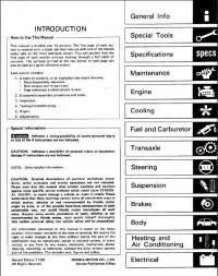
Detailed descriptions of standard workshop procedures, safety principles and service operations are not included. Please note that this manual does contain warnings and cautions against some specific service methods which could cause PERSONAL INJURY, or could damage a vehicle or make it unsafe. Please understand that these warnings cannot cover all conceivable ways in which service, whether or not recommended by Honda Motor, might be done, or of the possible hazardous consequences of each conceivable way, nor could Honda Motor investigate all such ways. Anyone using service procedures or tools, whether or not recommended by Honda Motor, must satisfy himself thoroughly that neither personal safety nor vehicle safety will be jeopardized.
CONTENTS
- General Info
- Special Tools
- Specifications
- Maintenance
- Engine
- Cooling
- Fuel and Emissions
- Clutch
- Manual Transmission
- Automatic Transmission
- Driveshafts
- Power Steering
- Suspension
- Вrakes
- Body
- Heater and Air Conditioner
- Electrical
Language: English
Format: PDF
Honda Prelude Manuals Index
-
-
Honda Prelude 1987 Workshop Manual
- (970 Pages)
- (Free)
-
-
Honda Prelude 1987 Workshop Manual L4 1955cc.html
- (3,387 Pages)
- (Free)
-
-
Honda Prelude 1988 1990 Workshop Manual
- (1,739 Pages)
- (Free)
-
-
Honda Prelude 1992 1996 Workshop Manual
- (2,186 Pages)
- (Free)
-
-
Honda Prelude 1994 Workshop Manual 2.2L SOHC
- (7,797 Pages)
- (Free)
-
-
Honda Prelude 1996 Workshop Manual 2.3L DOHC 16_Valve
- (8,773 Pages)
- (Free)
-
-
Honda Prelude 1997 Workshop Manual 2.2L DOHC
- (13,025 Pages)
- (Free)
-
-
Honda Prelude 1997 Workshop Manual 2.2L DOHC MFI
- (13,025 Pages)
- (Free)
-
-
Honda Prelude 1998 Workshop Manual 2.2L DOHC
- (12,439 Pages)
- (Free)
-
-
Honda Prelude 1999 1997 Workshop Manual
- (1,380 Pages)
- (Free)
Honda Prelude Owners Manual
-
-
1990 Honda Prelude Owners Manual
- (143 Pages)
- (Free)
-
-
1991 Honda Prelude Owners Manual
- (146 Pages)
- (Free)
-
-
1992 Honda Prelude Owners Manual
- (225 Pages)
- (Free)
-
-
1993 Honda Prelude Owners Manual
- (224 Pages)
- (Free)
-
-
1994 Honda Prelude Owners Manual
- (233 Pages)
- (Free)
-
-
1995 Honda Prelude Owners Manual
- (236 Pages)
- (Free)
-
-
1996 Honda Prelude Owners Manual
- (231 Pages)
- (Free)
-
-
1997 Honda Prelude Owners Manual
- (247 Pages)
- (Free)
-
-
1998 Honda Prelude Owners Manual
- (278 Pages)
- (Free)
-
-
2000 Honda Prelude Owners Manual
- (284 Pages)
- (Free)
Honda Prelude Misc Document
-
-
Honda Prelude 1979 Misc Documents Brochure
- (11 Pages)
- (Free)
-
-
Honda Prelude 1980 Misc Documents Brochure
- (12 Pages)
- (Free)
-
-
Honda Prelude 1981 Misc Documents Brochure
- (16 Pages)
- (Free)
-
-
Honda Prelude 1984 Service Repair Manual
- (705 Pages)
- (Free)
-
-
Honda Prelude 1985 Coupe Service Repair Manual
- (137 Pages)
- (Free)
-
-
Honda Prelude 1985 Service Repair Manual
- (518 Pages)
- (Free)
-
-
Honda Prelude 1988 Misc Documents Brochure
- (26 Pages)
- (Free)
-
-
Honda Prelude 1989 Misc Documents Brochure
- (24 Pages)
- (Free)
-
-
Honda Prelude 1991 Service Repair Manual
- (970 Pages)
- (Free)
-
-
Honda Prelude 1993 Service Repair Manual
- (1,408 Pages)
- (Free)
-
-
Honda Prelude 1997 Misc Documents Wiring Diagrams
- (54 Pages)
- (Free)
-
-
Honda Prelude 2000 Service Repair Manual
- (1,376 Pages)
- (Free)
-
-
Honda Prelude 2001 Service Repair Manual
- (1,376 Pages)
- (Free)
Service Manual Honda Prelude Mark II (series AB, BA1/BA2/BA3/BA6, BB) с бензиновыми двигателями: A18A/ET/ES 1.8 л (1829 см³) 102-106-125 л.с./75-78-92 кВт. Профессиональное руководство по ремонту и техническому обслуживанию для СТО легковой автомобиль малого среднего класса Хонда Прелюд 2 с цельнометаллическими несущими кузовами двухдверное купе переднеприводные модели второго поколения выпуска с ноября 1982 по 1987 год
ЕСЛИ ВЫ ВИДИТЕ ОШИБКУ 406 Not Acceptable и не видите документ, то скорей всего у Вас IP РФ и его надо сменить, на любой другой страны, с помощью VPN ( Scribd и SlideShare блокируют посетителей с Российским IP).
Видео Хонда Прелюд с 1982 тест-драйв (Honda Prelude mk2)
Хонда Прелюд 1982-1987 общая информация (Honda Prelude Mark II)
В оригинальном руководстве по ремонту «Honda Motor Co., LTD», на английском языке, дается подробное описание технологических процедур по демонтажу, сборки, диагностики, ремонту отдельных узлов и техническому обслуживанию автомобилей HONDA Prelude и его модификации 1983 года выпуска.
Состоит из следующих глав:
- Раздел Основная информация
- Раздел Специальный инструмент
- Раздел Спецификация
- Раздел Настройки и обслуживание
- Раздел Двигатель
- Раздел Система охлаждения
- Раздел Системы впуска и выпуска
- Раздел Трансмиссия
- Раздел Рулевое управление
- Раздел Подвеска
- Раздел Тормозная система
- Раздел Кузов и салон
- Раздел Системы отопления и кондиционирования
- Раздел Электрические схемы и электрооборудование
Контрольная лампа недостаточного давления масла
Контрольная лампа давления масла показывает, достаточное ли давление масла в двигателе. В нормальном состоянии лампа зажигается при повороте ключа зажигания в положение «II» и сразу гаснет. Если лампа продолжает гореть после запуска двигателя или внезапно зажигается во время езды, немедленно заглушите двигатель и проверьте уровень моторного масла. Даже если уровень масла достаточен, необходимо проверить автомобиль у дилера «Хонда» перед следующей поездкой.
ПРИМЕЧАНИЕ. Лампа зажигается только в случае недостаточного давления масла в двигателе, но не является показателем уровня моторного масла.
ВНИМАНИЕ! Езда при постоянно включенной лампе недостаточного давления масла может вызвать быструю и серьезную поломку двигателя.
Контрольная лампа проверки состояния двигателя (стандартное оборудование для некоторых модификаций) Эта лампа загорается на несколько секунд сразу же после запуска двигателя. Лампа загорается и не гаснет, если в системе выпуска отработанных газов имеются неполадки. Если лампа зажигается во время движения, постарайтесь избежать езды на высокой скорости и проверьте систему как можно скорее у дилера «Хонда». Контрольная лампа заряда аккумуляторной батареи Контрольная лампа заряда аккумуляторной батареи загорается, если в системе подзарядки имеются неполадки, а также в случае, если зажигание включено, но двигатель еще не запущен. Если лампа зажигается во время движения, остановите автомобиль на обочине, выключите зажигание и проверьте натяжение ремня генератора. Прогиб ремня в месте, указанном на рисунке, при усилии 98 Н (10 кГс) должен составлять 10-12 мм.
! ПРЕДУПРЕЖДЕНИЕ
• Если двигатель какое-то время работал, отдельные его части могли нагреться настолько, что вызовут ожог.
• В некоторых модификациях необходимо держать руки дальше от вентилятора радиатора. Вентилятор может неожиданно автоматически включиться и работать до 15 минут даже после того, как двигатель будет выключен.
ПРИМЕЧАНИЕ. Если необходимо, проверьте систему подзарядки аккумулятора у дилера «Хонда».
Контрольные размеры кузова Honda Prelude 1983
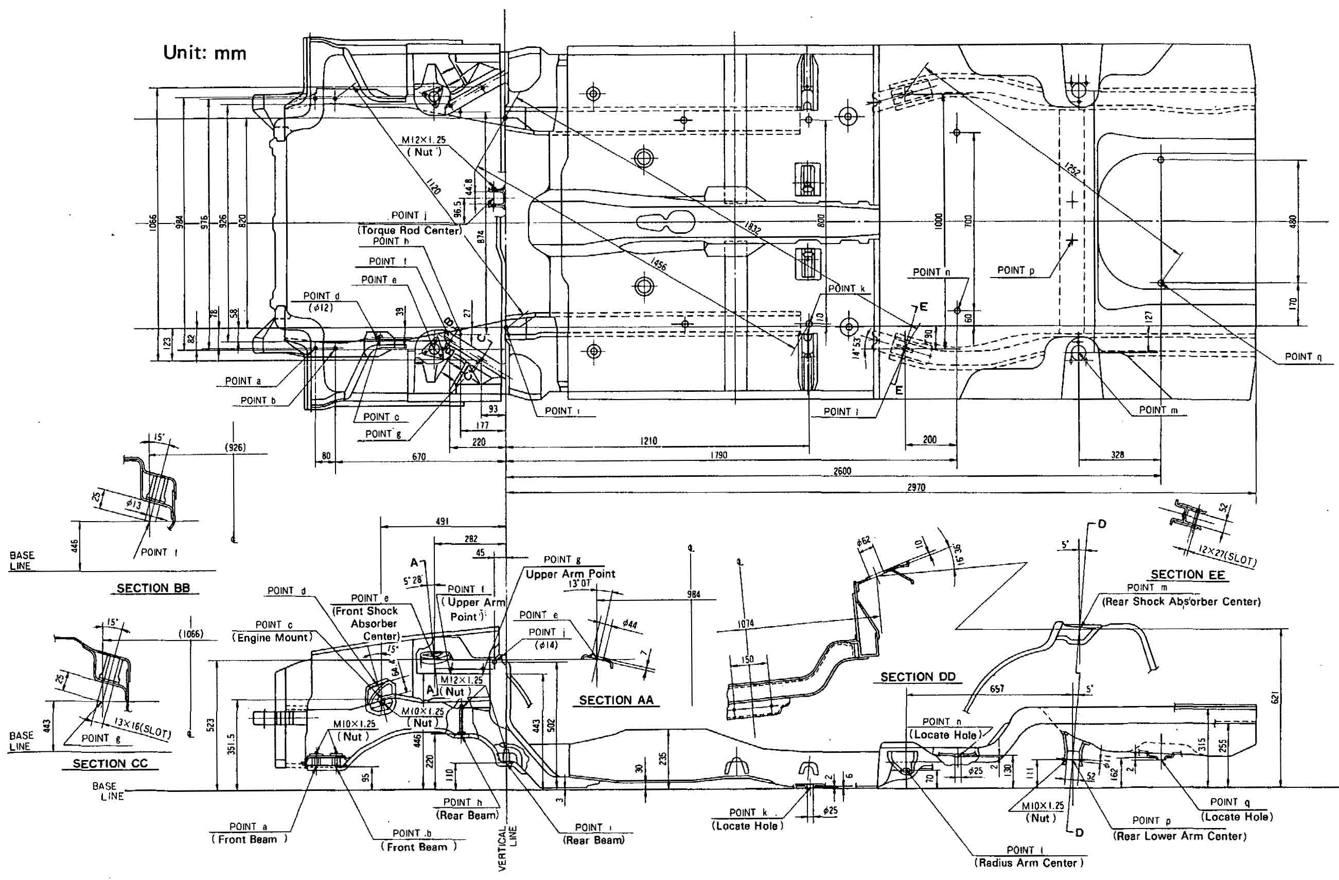
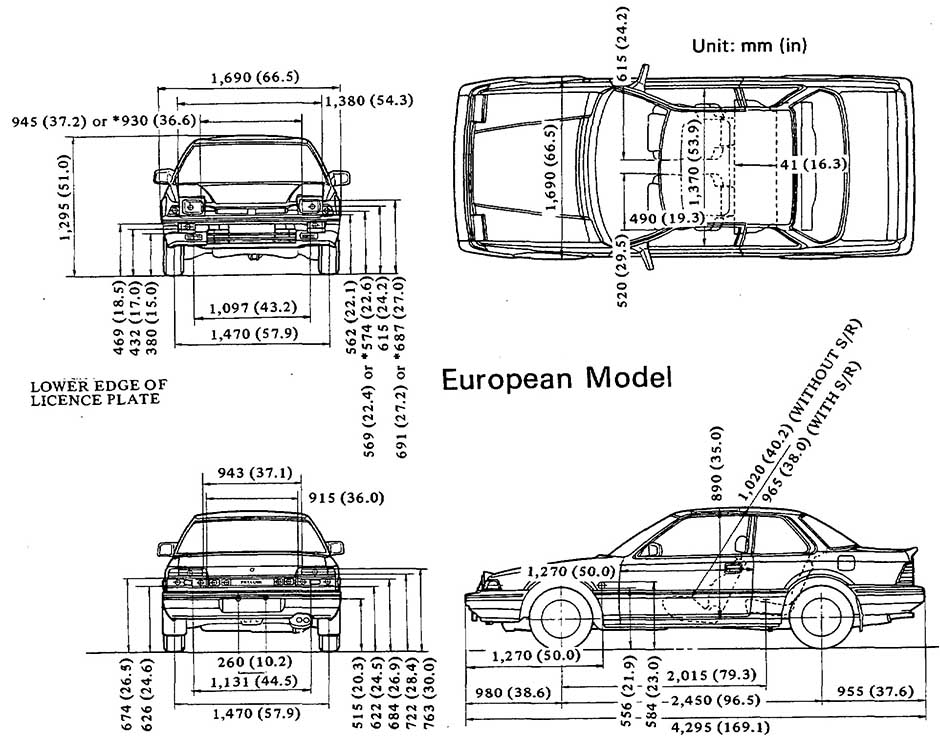
| № | Спецификация / Specs | Данные |
| Габариты (мм/mm) и масса (кг/kg) / Dimensions and Weight | ||
| 1 | Длина / Length | 4295 |
| 2 | Ширина (без/с зеркалами) / Width | 1690 |
| 3 | Высота (загружен/пустой) / Height | 1295 |
| 4 | Колёсная база / Wheelbase | 2450 |
| 5 | Дорожный просвет (клиренс) / Ground clearance | 153 |
| 6 | Снаряжённая масса / Total (curb) weight | 995 |
| Полная масса / Gross (max.) weight | 1490 | |
|
Двигатель / Engine |
||
| 7 | Тип / Engine Type, Code | Бензиновый, жидкостного охлаждения, четырехтактный, A18A/ET |
| 8 | Количество цилиндров / Cylinder arrangement: Total number of cylinders, of valves | 4-цилиндровый, рядный, 12V, SOHC с верхним расположением одного распределительного вала |
| 9 | Диаметр цилиндра / Bore | 80.0 мм |
| 10 | Ход поршня / Stroke | 91.0 мм |
| 11 | Объём / Engine displacement | 1829 см³ |
| 12 | Система питания / Fuel supply, Aspiration | Два горизонтальных карбюратора / Twin CV |
| Атмосферный | ||
| 13 | Степень сжатия / Compression ratio | 9.5:1 |
| 14 | Максимальная мощность / Max. output power kW (HP) at rpm | 78 кВт (106 л.с.) при 5500 об/мин |
| 15 | Максимальный крутящий момент / Max. torque N·m at rpm | 155 Нм при 4000 об/мин |
|
Трансмиссия / Transmission |
||
| 16 | Сцепление / Clutch type | Однодисковое, сухое, с диафрагменной нажимной пружиной и гасителем крутильных колебаний, постоянно замкнутого типа |
| 17 | КПП / Transmission type | GM МКПП 5 пятиступенчатая механическая, двухвальная, с синхронизаторами на всех передачах переднего хода |
О Книге
- Название: Honda Prelude 1983 Service Manual
- Бензиновые двигатели: A18A/ET/ES 1.8 л (1829 см³) 102-106-125 л.с./75-78-92 кВт
- Выпуск с 1982 года
- Серия: «Workshop Manual»
- Год издания: ноябрь 1983
- Автор: Коллектив авторов
- Издательство: «Honda Motor Co., Ltd»
- Формат: PDF
- Страниц в книге: 705
- Размер: 55.87 МБ
- Язык: Английский — Graecum est, non legitur
- Количество электросхем: более 50