-
Contents
-
Table of Contents
-
Troubleshooting
-
Bookmarks
Quick Links
OWNER’S MANUAL
2007
990 ADVENTURE
990 ADVENTURE S
ART. NR. 3.211.149 EN
Related Manuals for KTM 990 ADVENTURE
Summary of Contents for KTM 990 ADVENTURE
-
Page 1
OWNER’S MANUAL 2007 990 ADVENTURE 990 ADVENTURE S ART. NR. 3.211.149 EN… -
Page 2: Introduction
INTRODUCTION We would like to congratulate you on your purchase of a KTM motorcycle. You are now the owner of a state-of-the-art sport motorcycle that guarantees to bring you lots of fun and enjoyment, provided that you clean and maintain it appropriately.
-
Page 3: Important Information
IMPORTANT INFORMATION INTENDED PURPOSE The KTM 990 Adventure is designed to resist the usual wear and tear of normal use on roads and easy terrain (unpaved roads). OWNER’S MANUAL Carefully read the entire Owner’s Manual before you start riding your motorcycle, even if this will take a little time. It contains use- ful tips and information on the best way to handle the motorcycle and how to protect yourself from injuries.
-
Page 4
The service work specified in the „Lubrication and Maintenance Schedule“ must be performed by an authorized KTM workshop. This is the only place that has the qualified technicians and the special tools required for the 990 Adventure. Be sure to have the workshop verify all service work carried out in the service manual to avoid losing your right to claim under the warranty. -
Page 5: Table Of Contents
GENERAL TIPS AND WARNINGS FOR STARTING THE MOTORCYCLE …….24 Instructions for initial operation ….24 Running in the LC8 engine .
-
Page 6
Checking the chain for wear ….. . .49 General informations about KTM disc brakes …50 Adjusting of free travel at the hand brake lever . -
Page 7: Serial Number Locations
» SERIAL NUMBER LOCATIONS Chassis number The chassis number is located on the right side of the steering head tube and on the type label. Write this number into the relevant area on page 1. Engine number, engine type The engine number and engine type are embossed in the engine case near the shift lever. Write this number into the relevant area on page 1.
-
Page 8: Operation Instruments
» OPERATION INSTRUMENTS Clutch lever The clutch lever [1] is located on the left side of the handlebar. The adjusting screw [A] is used to change the original position of the clutch lever (see maintenance work on chassis and engine). The clutch is hydraulically actuated and adjusts itself automatically.
-
Page 9: Multi-Functional Digital Speedometer
Use the MODE and SET [1] button to change the display and the basic settings in the display. Display [2] shows all of the information that may be of interest to you. 5 display modes can be selected with the MODE button. The indicator lamps [3] provide additional information on the motorcycle’s running condition. Display TEST…
-
Page 10
OPERATION INSTRUMENTS CLOCK TRIP 1 TRIP 2 TRIP F » CLOCK You will recognize the CLOCK display by the blinking dots between the hours and minutes. It displays the speed, temperature of the cooling liquid and the clock. To switch to the next display mode, press the MODE button. The speed, temperature of the cooling liquid and the total kilometers or miles traveled are shown in the ODO mode. -
Page 11: Setting Options In The Display
OPERATION INSTRUMENTS 10 sec » Setting options in the display KILOMETERS OR MILES. You can have the speed and distance shown in kilometers or miles in the display. The dis- play can be adapted to the respective country on long-distance trips. To switch from kilometers to miles, switch on the ignition and press the MODE [1] button for approx.
-
Page 12
» OPERATION INSTRUMENTS RESETTING TRIP 2 The trip meter 2 runs continuously and counts up to 999.9. It can be used similarly to TRIP 1 or together with a switch available as an accessory (see below) for trips according to a roadbook. -
Page 13: Cooling Liquid Temperature Display
OPERATION INSTRUMENTS 120°C (248°F) 110°C (230°F) 100°C (212°F) 70°C (158°F) 60°C (140°F) 50°C (122°F) 40°C (104°F) » Cooling liquid temperature display The temperature display [1] is shown in 7 bars. The more bars that light up, the hotter the cooling liquid. When the lowest bar lights up, the cooling liquid has reached a temperature of approx.
-
Page 14: Indicator Lamps
» OPERATION INSTRUMENTS Indicator lamps The green indicator lamp will blink in the blinker rhythm when the blinker is switched on. NOTE: The indicator lamp will blink faster when a blinker is broken. The green indicator lamp will light up when the gearbox is in an idling position.
-
Page 15: Abs Button – Models With Abs (Antilock Brake System)
NOTE: The brake system will still function but ABS control will no longer be active. Continue to drive carefully and have the ABS checked at an authorized KTM workshop. NOTE: The ABS warning lamp can also light up if there is a large deviation between the speed of the front and rear wheel in extreme driving situations, e.g.
-
Page 16: Tachometer
OPERATION INSTRUMENTS » Tachometer The tachometer shows the engine speed in revolutions per minute. Do not run the engine beyond the black mark at 9500 rpm. The speed limiter will set in at 9600 rpm, drastically reducing the engine power above this rotational speed.
-
Page 17: Combination Switch
OPERATION INSTRUMENTS » Combination switch The rocker switch LIGHTS [1] actuates the high beam or low beam. = High-beam light = Low-beam light The light signal (high beam) is actuated with button [2]. The indicator switch [3] returns to central position after actuation. Press flasher switch towards switch housing to switch off the flasher.
-
Page 18: Storage Compartment
Filler caps The 990 Adventure has 2 separate fuel tanks. Both filler caps [2] can be locked and are equipped with a tank vent system. To open, insert the ignition key, turn 45° in a clockwise direction and fold up the filler cap.
-
Page 19: Fuel Taps
» OPERATION INSTRUMENTS Fuel taps Both fuel taps [1] must be open when the motorcycle is running. The level in the fuel tanks is equalized by means of a connecting hose. Only close the fuel taps to remove the tanks.
-
Page 20: Side Stand
» OPERATION INSTRUMENTS Side stand Fold the side stand [1] forward to the stop with your foot and put the weight of the motor- cycle on the stand. Make sure it is standing securely on a firm surface. The side stand is linked to the safety start system;…
-
Page 21: Compression Damping Of Fork
» OPERATION INSTRUMENTS Compression damping of fork The fork’s damping action during compression travel (compression damping) can be adjusted. This allows you adjust the damping behavior to match your driving style and the payload. The adjusting screws [2] are located under the cap [1] on the lower end of the fork legs. More information is provided in the chapter «Adjusting the fork and shock absorber.“…
-
Page 22: Damping Action During Compression Of Shock Absorber
The damping rate can be adjusted in the low and high-speed range (Dual Compression Control). The designation low and high-speed refers to the movement of the shock absorber and not to the motorcycle’s driving speed. The adjusting screw [1] for the low-speed range can be adjusted with a screwdriver.
-
Page 23: Rebound Damping Of Shock Absorber
OPERATION INSTRUMENTS » Rebound damping of shock absorber The shock absorber’s damping action during rebound travel (rebound damping) can also be adjusted. This allows you adjust the damping behavior to match your driving style and the payload. The adjusting screw [1] is located on the bottom of the shock absorber. More information is provided in the chapter «Adjusting the fork and shock absorber.“…
-
Page 24: Grips
» OPERATION INSTRUMENTS Grips The passenger can hold on to both grab handles [1]. Footrests The passenger footrests [2] fold up. Alarm system An alarm system can be retrofitted. Ask your authorized KTM shop for details.
-
Page 25: General Tips And Warnings For Starting The Motorcycle
GENERAL TIPS AND WARNINGS FOR STARTING THE MOTORCYCLE Instructions for initial operation – Make sure the work for the „pre-delivery inspection“ was performed by your author- ized KTM workshop. The DELIVERY CER- TIFICATE and SERVICE MANUAL will be handed over when you pick up your vehicle.
-
Page 26: Accessories And Payload
– Models with ABS: The ABS is designed to be used with the tires authorized by KTM and works best with these tires. The ABS function cannot be guaranteed if other tires are used. – Models with ABS: an incorrect tire pres-…
-
Page 27: Driving Instructions
Arrange for the braking system to be checked by a KTM specialist, as com- plete failure of the braking system can be avoided.
-
Page 28
Make sure your luggage is correctly fastened before you drive off. Never drive faster than 130 kph (80 mph) if your motorcycle is loaded with cases or other baggage. They will impair the motorcycle’s handling at higher speeds and can easily cause it to go out of control. -
Page 29: Starting The Engine
If the engine is not switched off, engine damage will occur within a short period of time. Check the engine oil level or contact a ktm workshop. – Maximum period for continuous starting: 5 seconds. Wait at least 5 seconds before try- ing again.
-
Page 30: Starting Off
– If this is not the case, refill the tank – if sufficient fuel is in the tank, pro- ceed as described in the „Trouble- shooting“ section or contact a KTM dealer. NOTE: This motorcycle is equipped with a safety start- ing system.
-
Page 31: Braking – Models Without Abs (Antilock Brake System)
Check the engine oil level or con- tact an authorized KTM workshop. – Never have the throttle wide open when changing down to a lower gear. The engine will overspeed, damaging the valves.
-
Page 32: Switching Off The Abs
– If the resistance in the hand brake lever or foot brake pedal feels „spongy“ (too much play), this is an indication that something is wrong with the brake sys- tem. Don’t ride your motorcycle anymore without first having the brake system looked over by a KTM dealer.
-
Page 33: Stopping And Parking
INFORMATION ABOUT THE SIDE STAND Use your foot to push the side stand forward as far as possible, and lean your motorcycle to the side. Make sure that your motorcycle is standing safely on solid ground. Just in case, you can also put in a gear.
-
Page 34
Make sure that the ground is solid and that your motorcycle is standing securely. – The center stand is designed to hold the weight of the motorcycle only. By sitting on the motorcycle, you will put additional weight on the center stand, possibly causing the cen- ter stand or frame to be damaged or the motorcycle to fall down. -
Page 35: Fuel
Please use unleaded fuel only. The 990 Adventure has 2 tanks with 1 filler cap each. Both filler caps can be locked and are equipped with a tank vent system. To open, insert the ignition key, turn 45° in a clock- wise direction and fold up the filler cap.
-
Page 37: Periodic Maintenance Schedule
Clean the oil jet for the clutch lubrication Check rubber boots for cracks or leaks Check fault memory with the KTM diagnosis tool Perform a status check of neutral, clutch, 2nd/3rd gear and side stand switch using the KTM diagnosis tool…
-
Page 38
Check/adjust smooth operation, free travel of handbrake/footbrake levers Check bolts of brake system for tight fit Check the ABS fault memory using the KTM diagnostics tool Check shock absorber and fork for leaks and proper operation Clean fork dust sleeves… -
Page 39: Periodic Maintenance Schedule
If motorcycle is used for competition 7500 km service should be carried out after every race! Service intervalls should never be exceeded by more than 500 km. Maintenance work done by KTM autorized workshops is not a substitute of care and checks done by the rider! 990 ADVENTURE 2007…
-
Page 40
PERIODIC MAINTENANCE SCHEDULE 990 ADVENTURE 2007 VITAL CHECKS AND CARE PROCEDURES TO CONDUCTED BY THE OWNER OR THE MECHANIC Check oil level Check brake fluid level Check brake pads for wear Check lighting system for proper operation Check horn for proper operation… -
Page 41: Maintenance Work On Chassis And Engine
– All screws and nuts must be tightened to the specified torque figures using a torque wrench. If screws or nuts are not adequately tight- ened, they can become loose and cause the motorcycle to go out of control while you drive. Tightening the screws and nuts too tightly can damage the thread and components.
-
Page 42: Removing And Remounting The Seat
The tool set [4] and an extension piece [5] for some of the wrenches in the tool set are located in the pocket under the seat. The 990 Adventure S model (without ABS) has an additional storage compartment under the cover [6].
-
Page 43: Adjusting The Fork And Shock Absorber
There are a number of ways to adjust the fork and shock absorber to match the chassis to your driving style and the payload. We have provided a table with pragmatical values to help you tune up your motorcycle. These tune-up specifications are reference values only and should serve as a basis for your per- sonal chassis and suspension tuning.
-
Page 44: Adjusting The Spring Preload On The Fork
» MAINTENANCE WORK ON CHASSIS AND ENGINE Adjusting the spring preload on the fork The fork spring preload can be adjusted by turning the adjusting screws [4] (wrench size 24 mm) ± 5 mm (0,2 in). Turning in a clockwise direction will increase the preload, turning in a counterclockwise direc- tion will decrease the preload.
-
Page 45: Compression Damping Of Shock Absorber
– unscrew the respective number of clicks for the specific type of shock absorber in a coun- terclockwise direction. 990 Adventure ..20 clicks 990 Adventure S ..20 clicks »…
-
Page 46: Rebound Damping Of Shock Absorber
– Turn the adjusting screw in a counterclockwise direction the number of turns specified for the respective type of shock absorber. 990 Adventure ..1.5 turns 990 Adventure S ..1.5 turns The damping unit of the shock absorber is filled with high-compression nitrogen.
-
Page 47: Adjusting The Preload Of The Shock Absorber
Breathing the fork legs Breath the fork legs regularly (see Maintenance Schedule). To breath, place the motorcycle on the side stand and briefly remove the bleeder screws [2] to allow any overpressure to escape from the fork. Excessive pressure in the interior of the fork can cause leaks in the fork. If your fork is leak-…
-
Page 48: Cleaning The Dust Sleeves Of The Telescopic Fork
Checking the chain tension Place the motorcycle on the side stand and switch the transmission to idle. Press the chain upwards under the lower chainguard screw [4]. The difference to the sagging chain should be 35 — 40 mm (1.37 ……
-
Page 49: Correct Chain Tension
If you don’t happen to have a torque wrench at hand, make sure you have the tightening torque corrected by a KTM dealer as soon as possible. A loose axle may lead to an unstable driving behavior of your motorcycle.
-
Page 50: Chain Maintenance
– The chain does not have a chain joint for safety reasons. Always have the chain replaced in an authorized KTM workshop where the service technicans have the required riveting tool. – Never mount a normal chain joint.
-
Page 51: General Informations About Ktm Disc Brakes
KTM motorcycle in road traffic. The brake pads design and friction factor and therefore the braking power can deviate significantly from original KTM brake pads. If you use dif- ferent brake pads than those provided with the original equipment, it cannot be war- ranted that they are authorized for use in road traffic.
-
Page 52
DOT 4 brake fluid. Do not, in any event, use DOT 5 brake fluid. It is based on silicone oil and is dyed purple. KTM motorcycle gaskets and brake hoses are not designed for DOT 5 brake fluid. -
Page 53
ABS cannot be warranted. – The ABS is designed to be used with the tires authorized by KTM and works best with these tires. The ABS function cannot be guaranteed if other tires are used. -
Page 54: Adjusting Of Free Travel At The Hand Brake Lever
– If the brake fluid level drops below the minimum either the brake system has a leak or the brake pads are completely worn down. In this case, consult an authorized KTM dealer immediately.
-
Page 55: Checking Rear Brake Fluid Level
– If the brake fluid level drops below the minimum either the brake system has a leak or the brake pads are completely worn down. In this case, consult an authorized KTM dealer immediately.
-
Page 57: Dismounting And Mounting The Front Wheel
MAINTENANCE WORK ON CHASSIS AND ENGINE Dismounting and mounting the front wheel Jack the motorcycle up at the underride protection until the front wheel no longer touches the ground. Loosen the collar screw [1] and the clamp screws [2] at both fork leg axle passages. Unscrew the collar screw approx.
-
Page 58
Now you can tighten the clamp screws on both fork leg axle passages to 15 Nm. – If you do not have a torque wrench to mount the wheel, have the torques corrected by an authorized KTM workshop as soon as possible. A loose axle passage can cause the motorcycle’s handling performance to become instable. -
Page 59: Dismounting And Mounting The Rear Wheel
– If you don’t happen to have a torque wrench at hand, make sure you have the tighten- ing torque corrected by a KTM dealer as soon as possible. A loose wheel spindle may lead to an unstable driving behavior of your motorcycle.
-
Page 60: Tires, Air Pressure
The ABS function can no longer be guaranteed. – Models with ABS: The ABS is designed to be used with the tires authorized by KTM and works best with these tires. The ABS function cannot be guaranteed if other tires are used.
-
Page 61: Checking Spoke Tension
A clear tone must be the result. Dull tones indicate loose spokes. If necessary, have the spokes retightened and the wheel centered by a KTM dealer. – If you continue to drive with loose spokes, the spokes can tear and lead to an instable handling performance.
-
Page 62: Battery
Never operate the motorcycle with a run-down battery or without the battery. This can dam- age the electronic components or safety equipment in either caseand the motorcycle will no longer be roadworthy.
-
Page 63: Demounting And Mounting The Battery
Never disconnect the battery while the engine is running. This will destroy the rectifier- regulator. STORAGE: If the motorcycle is being immobilized for longer periods of time, remove and charge the battery. Storage temperature 0 — 35°C (32 — 95°F), avoid direct sunlight. Charge the battery every 3 months.
-
Page 64: Charging The Battery
5.5 amperes To charge the battery while mounted, always use the KTM battery charger (Item no. 58429074000) to ensure that the electric system is not damaged by excess voltage. Always remove the battery if using other battery chargers! You can also use this charging device to test the off-load voltage and startability of the battery and generator.
-
Page 65: Main Fuse
Two fuses for the ABS are located under the starter relay. Remove the caps and check the fuses [7] and [8]. Replace blown fuses with the same type of fuse. Visit an authorized KTM workshop if the new fuse blows again.
-
Page 66: Fuses For Individual Current Consumers
[1]. Spare 10, 15, 25 and 40-ampere fuses [2] are also located next to the stor- age compartment. Replace a blown fuse only with an equivalent one. Visit an authorized KTM workshop if the new fuse blows again.
-
Page 67: Replacing The Headlight Lamps
MAINTENANCE WORK ON CHASSIS AND ENGINE Replacing the headlight lamps Remove the 5 screws on the left and right and take off both side covers [1]. Use a screw- driver to detach the retaining tabs [2], tilt the windshield and headlight forward and pull the connector off the connector support.
-
Page 68
» MAINTENANCE WORK ON CHASSIS AND ENGINE PARKING LIGHT BULB [C] : Pull the bulb socket [7] out of the reflector and pull the bulb out of the bulb socket. USA design: The parking light [E] is located in the upper part of the headlight in the USA design. Bulb [F] (see Technical specifications –… -
Page 69: Adjusting The Headlight Range
Make a mark on a light wall behind a level surface at a height of 830 mm (32.7 in) (990 Adventure S) or 790 mm (31.1 in) (990 Adventure) respectively. Position your motorcycle loaded ready for the trip (baggage, driver, passenger) 10 meters away from the wall and switch on the low beam.
-
Page 70: Replacing The Flasher Bulbs
Replacing the flasher bulbs Remove the screw on the back of the turn signal, carefully fold the lens [5] towards the motorcycle and remove. Slightly depress the bulb, turn it approx. 30° counterclockwise and pull it out of the socket.
-
Page 71: Cooling System
If the fan is not working, and there appears to be sufficient cool- ing liquid, the only thing you can do is to drive on to your nearest authorized KTM work- shop at the least possible engine load.
-
Page 72: Checking The Cooling Liquid Level In The Compensating Tank
If you need to add cooling liquid quite often, the cooling system may leak. If the compen- sating tank is empty, also check the cooling liquid level in the radiator. Have the cooling system checked by an authorized KTM workshop. »…
-
Page 73: Checking The Cooling Liquid Level In The Radiator
If any cooling liquid is missing, the cooling system may leak. Have the cooling system checked by an authorized KTM workshop. If more than 1 liter (0.26 USgal) of cooling liquid needs to be added, the cooling system must be bled.
-
Page 74: Bleeding The Cooling System
Remove the bleeder screw [4] on the left side of the radiator. To be able to completely bleed the cooling system, raise the motorcycle approx. 50 cm in the front. Add cooling liquid until it runs out of the discharge opening without bubbles and immedi- ately mount the screw to prevent more air from getting into the radiator.
-
Page 75: Changing The Original Position Of The Clutch Lever
KTM uses biodegradable, hydraulic mineral oil to actuate the hydraulic clutch. Do not mix this oil with any other hydraulic oil. Always use original KTM hydraulic oil (available from your authorized KTM workshop) to make sure your clutch operates smoothly.
-
Page 76: Checking The Engine Oil Level
Only use fully synthetic engine oils that meet the JASO MA quality requirements (see infor- mation on the can). KTM recommends Motorex Power Synt 4T in the 10W/50 viscosity (for temperatures over 0°C, 32°F) or 5W/40 (for temperatures under 0°C, 32°F).
-
Page 77: Changing The Engine Oil And The Oil Filter Cleaning The Oil Screen
Since many parts must be demounted for an oil change, we recommend having the engine oil changed by an authorized KTM workshop. During the guaranty period, the oil change must be performed by an authorized KTM mechanic. Otherwise, the guarantee will become void.
-
Page 78
» MAINTENANCE WORK ON CHASSIS AND ENGINE Remove the 6 screws and the cover [4]. Remove the 5 screws, take off the left panel [5] and disconnect the turn signal cable. Close both fuel taps [6] on the connecting line. -
Page 79
» MAINTENANCE WORK ON CHASSIS AND ENGINE Remove the 3 screws [1], lift the tank approx. 15 mm and carefully tilt to the side. Disconnect the fuel lines, disconnect the connector for the fuel pump and the pickup cable (fuel level) and set down the tank. -
Page 80
» MAINTENANCE WORK ON CHASSIS AND ENGINE Carefully pull the oil screen [7] out of the oil tank. Thoroughly clean the drain plugs, the cover and both oil screens. Clean all rubber seal rings and check for damage. Replace if necessary. Mount the oil drain plug on the engine with a new seal ring and tighten to 20 Nm. -
Page 81
O-ring. Tighten the screws to 6 Nm. Only use original KTM oil filters. The engine can be damaged if other filters are used. Mount the oil drain plug on the oil tank with a new seal ring and tighten to 20 Nm. -
Page 82
» MAINTENANCE WORK ON CHASSIS AND ENGINE Add 2.5 liters (0.7 USgal) of fully synthetic engine oil meeting the JASO MA standard (e.g. Motorex Power Synt 4T) and mount the oil dipstick. Start the engine, allow to run warm for 4 minutes and switch off the engine. -
Page 83: Activating The Ignition Curve For Low-Octane Fuel
» MAINTENANCE WORK ON CHASSIS AND ENGINE Activating the ignition curve for low-octane fuel If you are traveling to a country where fuel having at least 95 octane (RON) is not available, you can easily activate the corresponding ignition curve. A plug and socket connection [1] on a brown/black cable is located near the upper shock absorber holder .
-
Page 84: Trouble Shooting
If you have your motorcycle serviced as set forth in this manual, no malfunctioning is to be expected. Nevertheless, if an error does arise, we recommend that you look for the error according to the following chart. Please note that you cannot perform all of the work yourself. If you are not sure, contact your KTM dealer. TROUBLE…
-
Page 85
Visit an authorized KTM workshop Switch to neutral gear Have the air filter/fuel filter replaced at an authorized KTM workshop Visit an authorized KTM workshop Activate the ignition curve for 95 octane, if fuel with at least… -
Page 86
Contact an authorized KTM workshop. Bleed the cooling system (see Maintenance work) Have the thermostat checked (opening temperature 75°C, 167°F) or replaced; contact an authorized KTM workshop Visit an authorized KTM workshop Stop, switch off the ignition, start again Replace the ABS fuses (under the right engine cover) -
Page 87
Recharge the battery according to the relevant instructions. Voltage regulator and generator should be checked by an authorized KTM workshop. Replace fuse HORN BRAKELIGHT SPEEDO. Check the pickup cable for damage, visit an authorized KTM workshop Blink code 06: FI blinks 6x short, pause ERROR DESCRIPTION… -
Page 88
» TROUBLE SHOOTING The blink code indicates which component is affected by an error. This allows the error to be identified if no diagnosis tool is available. BLINK CODE SIGNAL / COMPONENT Coolant temperature sensor Air temperature sensor Ambient air pressure sensor Tilt angle sensor Lambda probe for rear cylinder Lambda probe for front cylinder… -
Page 89: Cleaning
(e.g. Motorex 900) and cleaned with a brush. – After the motorcycle has been rinsed with a soft water jet, it should be dried by air pressure and a cloth. Then take a short drive until the engine has reached the working temperature and also use the brakes.
-
Page 90: Storage
– Take a short, careful test ride first. NOTE: Before you put your motorcycle away for the winter, you have to check all parts for their function and wear. Should any service jobs, repairs, or any refitting be necessary, you should have them carried out during the off-season (lower workload at mechanics’ shops). This…
-
Page 91: Technical Specifications – Chassis
USA: high beam + low beam H4 12V 60/55 W (socket P43t) position light front + rear 12V 5W (socket W2.1×9.5d) indicator lamps LED stoplight 12V 21W (socket BA15s) * further tire releases are available on the Internet at www.ktm.com » 4 liters (1 USgal) reserve…
-
Page 92
TECHNICAL SPECIFICATIONS – CHASSIS CHASSIS 990 ADVENTURE / 990 ADVENTURE S Lighting flasher 12V 10W (socket BA15s) licens plate illumination 12V 5W (socket W2.1×9,5d) Battery maintenance-free battery 12V 11.2 Ah Steering head angle 63.4° Wheel base 1570 mm (61.8 in) Seat height, unloaded ADVENTURE: 860 mm (33.8 in), ADVENTURE S: 915 mm (36 in) -
Page 93
TECHNICAL SPECIFICATIONS – CHASSIS TIGHTENING TORQUES – CHASSIS HH clamp bolts on top triple clamp HH clamp bolts for steering stem HH clamp bolts on bottom triple clamp AH bolt for handlebar mount Collar bolts for handlebar clamps HH clamp bolts on fork leg axle passages Collar screw on front wheel spindle Collar nut wheel spindle rear Collar nut for swing arm bolt… -
Page 94
TECHNICAL SPECIFICATIONS – CHASSIS TIGHTENING TORQUES – CHASSIS Exhaust nuts on manifold HH bolts on exhaust suspension Spoke nipple HH nuts on rear sprocket bolts Hexagon nut on engine sprocket Engine carrier bolts HH bolts for side stand bracket — engine HH bolts side stand bracket — side stand console HH bolts side stand mounting HH bolt spring retainer side stand… -
Page 95: Technical Specifications – Engine
TECHNICAL SPECIFICATIONS – ENGINE ENGINE 990 LC8 Design Liquid-cooled, 2-cylinder 4-stroke engine with 75° V arrangement with balancer shaft and electric starter Displacement 999 cc Bore / Stroke 101/62.4 mm Compression ratio 11.5:1 Fuel unleaded fuel with at least RON 95 (USA: Premium PON 91*) / RON 80 — 94 for other ignition curve) Valve timing 4 valves controlled over bucket tappet and 2 camshafts, camshaft drive with gears/chain Valve diameter…
-
Page 96: Engine Oil
Only use fully synthetic engine oils that meet the JASO MA quality requirements (see infor- mation on the can). KTM recommends Motorex Power Synt 4T in the 10W/50 viscosity (for temperatures over 0°C, 32°F) or 5W/40 (for temperatures under 0°C, 32°F).
-
Page 97: Head Word Index
» HEAD WORD INDEX ABS button – models with ABS (antilock brake system) ..14 ABS fuses – models with ABS (antilock brake system) ..64 ABS warning lamp – models with ABS (antilock brake system) . .14 Accessories and payload .
-
Page 98
Fuses for individual current consumers ….65 General informations about KTM disc brakes … . .50 General tips and warnings for starting the motorcycle . -
Page 99: Consumer Information For Usa Only
» CONSUMER INFORMATION FOR USA ONLY Sticker positions: 4 5 6…
-
Page 100
CONSUMER INFORMATION FOR USA ONLY [1] EAVP [4] Fuel level [7] Noise emission » [2] Type label USA [5] Before you go for the first ride [8] Technical information [2] Type label CAN [6] Vehicle emission [9] Exhaust system… -
Page 101: Consumer Information For Usa Only
NOISE EMISSION WARRANTY KTM Sportmotorcycle AG warrants that this exhaust system, at the time of sale, meets all applicable U.S. EPA Federal noise standards. This warranty extends to the first per- son who buys this exhaust system for purposes other than resale, and to all subsequent buyers.
-
Page 102
10/2006 FOTO: MITTERBAUER KTM Group Partner KTM Sportmotorcycle AG A–5230 Mattighofen www.ktm.at…
- Manuals
- Brands
- KTM Manuals
- Motorcycle
- 990 ADVENTURE
- Repair manual
-
Contents
-
Table of Contents
-
Troubleshooting
-
Bookmarks
Quick Links
REPAIRMANUAL2003-2008
950/990 ADVENTURE
990 SUPER DUKE/R
950/990 SUPERMOTO/R
950 SUPER ENDURO
REPARATURANLEITUNG
MANUALE DI RIPARAZIONE
MANUEL DE RÉPARATION
MANUAL DE REPARACIÓN
Related Manuals for KTM 990 Adventure
Summary of Contents for KTM 990 Adventure
-
Page 1
REPAIRMANUAL2003-2008 950/990 ADVENTURE 990 SUPER DUKE/R 950/990 SUPERMOTO/R 950 SUPER ENDURO REPARATURANLEITUNG MANUALE DI RIPARAZIONE MANUEL DE RÉPARATION MANUAL DE REPARACIÓN… -
Page 3
KTM Group Partner… -
Page 5
1 SERVICE-INFORMATIONS 2 GENERAL INFORMATION 3 REMOVING AND REFITTING ENGINE 4 DISASSEMBLING ENGINE 5 SERVICING INDIVIDUAL COMPONENTS 6 ASSEMBLING ENGINE 7 ELECTRICAL / INJECTION 8 FUEL SYSTEM 9 TROUBLE SHOOTING 10 CHASSIS 11 TECHNICAL SPECIFICATIONS 12 PERIODIC MAINTENANCE SCHEDULE 13 WIRING DIAGRAMS… -
Page 7
12-10 to 12-28 13-2 to 13-141 13-2 to 13-159 KTM REPAIR MANUAL IN LOOSE-LEAF FORM STORING THE REPAIR MANUAL IN THE BINDER – Put the index into the binder. – Put the front page of the repair manual (210×297 mm) into the transparent pocket provided for this purpose on the outside of the binder. -
Page 9
X P L A N A T I O N P D A T I N G 3.206.009-E Repair Manual Basicversion Modelyear 2003 4/2003 3.206.016-E Updating of Rep.Manual 3.206.009-E Modelyear 2004 (Engine number with first digit “4“) 11/2003 3.206.025-E Updating of Rep.Manual 3.206.009-E Modelyear 2005 (Engine number with first digit “5“) 01/2005… -
Page 11
„NOTE” POINTS OUT USEFUL TIPS. Use only ORIGINAL KTM SPARE PARTS when replacing parts. The KTM high performance engine is only able to meet user expectations if the maintenance work is performed regularly and professionally. In accordance with the international quality management ISO 9001 standard, KTM uses quality assurance processes that lead to the highest possible product quality. -
Page 13
REPLY FAX FOR REPAIR MANUALS We have made every effort to make our repair manuals as accurate as possible but it is always possible for a mistake or two to creep in. To keep improving the quality of our repair manuals, we request mechanics and shop foremen to assist us as follows: If you find any errors or inaccuracies in one of our repair manual –… -
Page 15
GENERAL INFORMATION INDEX OIL SYSTEM ……….2-2 AIR INTAKE SYSTEM . -
Page 17: Oil System
Oil system Pressure pump draws engine oil from oil tank through oil filter and the oil return valve and pumps it past the pressure relief valve through the oil filter into the annular groove The main bearing , the conrod bearings and the spraying nozzle (front timing chain) are supplied with oil through holes in the…
-
Page 18
Intake system Fresh air is drawn into the filter box through the intake snorkel , past the carburetors and through the air filter The cleaned air is conducted to the combustion chamber through the carburetors and intake ports. The diagram for the injection engine is similar; the air flows to the intake ports through the throttle body instead of through the carburetor. -
Page 19
Secondary air system The secondary air system supplies fresh air to the emissions in the exhaust port, resulting in the afterburning (oxidation) of the emissions. A line leads from the filter box to the control valve which opens as soon as the throttle valves are opened. -
Page 20: Cooling System
Cooling system Closed thermostat The thermostat is closed if the temperature of the cooling liquid drops below 75° C. The water pump pumps the cooling liquid through the cylinder and cylinder heads and the thermostat Open thermostat The thermostat opens at 75° C. The water pump pumps the cooling liquid through the cylinder and cylinder heads , the aluminum cooler…
-
Page 21
ABS is switched off. To switch the ABS on again, stop and switch off the ignition. The ABS will be active again when you switch on the ignition. See the KTM ABS training documents for a detailed description of the ABS system. -
Page 22
SPECIAL TOOLS – ENGINE PART NO DESCRIPTION 309098 Seal Three-Bond 0113 080802 Crankshaft locking bolt 151.12.017.000 Gear puller 451.29.075.000 Tachometer 503.29.050.000 Bleeding syringe for hydraulic clutch 560.12.001.000 Universal-engine work stand 584.29.059.000 Loctite 648 green 20 ml 585.29.005.000 Protection sleeve for shaft seal ring of water pump 590.29.019.000 Valve spring mounter 590.29.021.044… -
Page 23
br bs bt cs ct dk dl dm dn ds dt ek el… -
Page 24
SPECIALTOOLS – CHASSIS PART NO DESCRIPTION 151.12.017.000 Gear puller 584.29.086.000 Pressing tool for swing arm bearing 584.29.089.000 Chassis tool holder 584.29.091.000 Press-in tool for bearing seat / rear wheel bearing 584.29.092.000 Knock-out tool for bearing seat 600.03.022.000 Center stand 600.10.013.000 Sleeve for pressing tool for swim arm bearing 600.29.018.000 Internal gear puller 28 mm… -
Page 25
2-10 Checking the oil level of the hydraulic clutch — 950/990 Adventure, 950 Supermoto/R To check the oil level in the master cylinder of the clutch remove the cover. For this purpose, remove bolts and cover together with the rubber boot . -
Page 26
The engine may have a poor idle behavior if the control unit is not reset. – Connect the KTM diagnostics tool, turn the ignition switch on and start the program. – Select «Extend»… -
Page 27
KTM diagnostics tool. If this step is omitted, the throttle cable clearance cannot be correctly adjusted. – Connect the KTM diagnostics tool, turn the ignition switch on and start the program. – Select «Extend» – Select «Device operation»… -
Page 28
The software can be downloaded from KTM’s dealer.net site; the software is transferred to the control unit via the KTM diagnostics tool (FAN). – Some exhaust systems require new «mapping». If these exhaust systems are replaced by the production system again, the «mapping»… -
Page 29
DMT program. NOTE: – If the DMT is not installed yet, install with the KTM diagnostics tool – If the program is already installed but the DMT icon does not appear on your screen, start the program under «Start» (in the task bar at the bottom of the screen) by clicking «Programs». -
Page 30
2-15 – The mapping file will be transferred to the ECU. CAUTION O NOT SWITCH OFF THE IGNITION OR DISCONNECT THE DIAGNOSTICS CABLE WHILE (» «). T ECU. THE FILE IS BEING TRANSFERRED FLASHING HIS CAN DAMAGE THE NOTE: – All of the indicator lamps in the digital speedometer will light up while the file is being transferred. -
Page 31: Table Of Contents
REFITTING THE ENGINE ……… .3-7 990 ADVENTURE REMOVING THE ENGINE .
-
Page 33: Removing The Engine
Removing the engine — 950 Adventure – Screw the center stand 600.03.022.000 onto the frame and jack up the motorcycle on a firm, even surface. – Remove the left bump rubber and lock the center stand with the lock 600.29.055.000 NOTE: if available, use the center stand already on the bike.
-
Page 34
– Unscrew the bolts and remove the intake snorkel together with the frame from the air filter box. – Disconnect the vent hose and the EPC hose and remove the upper half of the air filter box. – Turn the intake trumpet in a clockwise direction and remove. -
Page 35
– Disconnect the electric connections from the fan motor and the temperature switch – Drain the cooling liquid from the radiator and engine: see Chapter 12. – Detach the water hoses from the radiator (special pliers 600.29.057.100) and unscrew the radiator NOTE: fan and radiator shield do not need to be dismounted from the radiator. -
Page 36
– Unscrew the nut on the wheel spindle, pull out the rear wheel spindle, take the chain off of the rear sprocket and place over the side of the bracket . Remove the chain from the engine sprocket. – Detach the connector –… -
Page 37
– Use the trolley jack to position the attachment 600.29.055.100 on the engine, insert the bolt through the front of the engine bracket and fasten with the nut. Screw one of the bolts on the rear of the side stand fixture and slightly lift the engine. –… -
Page 38: Refitting The Engine
Refitting the engine — 950 Adventure – Before mounting the engine, attach the water, SLS and vacuum hoses (Öttiger clamps — special pliers 600.29.057.000 or spring- loaded band-type clamps — special pliers 600.29.057.100) – Position the swing arm and fix with the swing arm pivot on the right and a suitable pipe on the left.
-
Page 39
– Mount the front oil line inserting new O-rings. Tighten the bolts. NOTE: up to engine number 2-600-1186 a washer must be used to preload the O-rings on the oil terminal. – Align the side supports and battery case against the engine, insert the bolt and mount the nut. -
Page 40
– Place the chain over the pinion and rear sprocket, lift the rear wheel and slide the wheel spindle through. – Press the rear wheel towards the front to apply the chain tensioner and tighten the nut on the wheel spindle to 90 Nm. –… -
Page 41
3-10 – Screw on the radiator together with the fan and the radiator shield , tighten the bolts to 10 Nm. – Connect water hoses radiator (special pliers 600.29.057.100) – Attach the electric connections for the fan motor and the temperature switch –… -
Page 42
3-11 – Fit the upper battery cover and place a battery with battery cover into the battery compartment. – Fit the front battery compartment lid and connect both battery cables together to the connections on the front lid (start with the positive cable). -
Page 43
3-12 Removing the engine — 990 Adventure – Screw the center stand 600.03.022.000 onto the frame and jack up the motorcycle on a firm, even surface. – Remove the left bump rubber and lock the center stand with the lock 600.29.055.000 NOTE: if available, use the center stand already on the bike. -
Page 44
3-13 – Unscrew the bolts and remove the intake snorkel together with the frame from the air filter box. – Disconnect the vent hose and the EPC hose and remove the upper half of the air filter box. – Turn the intake trumpet in a clockwise direction and remove. -
Page 45
3-14 – Expose the electric lines of the lambda probes at the front and rear and disconnect plug-in connections – Unscrew both nuts on the front exhaust manifold flange on the cylinder head, loosen the exhaust clamp on the front exhaust manifold, pull the front exhaust manifold out of the rear exhaust pipe and remove. -
Page 46
3-15 – Disconnect the side stand switch and take the cable out of the cable clips. – Loosen the two bolts and the nut and remove the side stand. – Unscrew the clutch slave cylinder and the chainguard – Remove the adapter for the clutch slave cylinder and the chain securing guide –… -
Page 47
3-16 – Take off the positive starter cable cover . Unscrew the positive starter engine cable and draw out the wiring harness. – Detach connector on the starter relay. – Unscrew the ground connection – Pull off the cover from the positive terminal, unscrew the nut beneath it and remove the lines from the stud. -
Page 48
3-17 – Unscrew the ground wire connection – Detach the connector from the pulse generator – Detach the connector from the oil pressure switch , the temperature sensor and from the front and rear ignition coil. Remove any cable clips necessary. –… -
Page 49
3-18 Refitting the engine — 990 Adventure – Before mounting the engine, attach the water, SLS and vacuum hoses (Öttiger clamps — special pliers 600.29.057.000 or spring- loaded band-type clamps — special pliers 600.29.057.100) – Position the swing arm and fix with the swing arm pivot on the right and a suitable pipe on the left. -
Page 50
3-19 – Align the side supports and battery case against the engine, insert the bolt and mount the nut. – Mount the bolts (M10x23), lifting the engine slightly if necessary. Tighten the nut and bolts to 45 Nm. – Tighten the nut on the swing arm pivot to 130 Nm. –… -
Page 51
3-20 – Insert the locking pin in the pushrod. – Mount the adapter for the hydraulic clutch – Mount the chain securing guide and the adapter for the clutch slave cylinder – Screw on the clutch slave cylinder and the chainguard –… -
Page 52
3-21 – Screw on the radiator together with the fan and the radiator shield , tighten the bolts to 10 Nm. – Connect water hoses radiator (special pliers 600.29.057.100) – Attach the electric connections for the fan motor and the temperature switch –… -
Page 53
3-22 – Place the lower section of the air filter box onto the intake flange. CAUTION EMOVE THE CLOTH USED TO COVER THE INTAKE PORTS – Place the throttle body into the lower section of the air filter box. NOTE: The lower section of the air filter box must be raised slightly to make room for the plug-in connection of the throttle body –… -
Page 54
3-23 – Fill cooling liquid into the radiator, compensating tank and engine: see Chapter 12. – Fill engine oil: see Chapter 12. – Attach both tanks and fix them with the screws (M8x40). – Connect the tank line. – Mount the lower tank compartment and screw on the fuse box Mount the fuse box cover. -
Page 55
3-24 Dismounting the engine — 990 Super Duke NOTE: the procedure for dismounting the engine is the same as the procedure used for the 950 Adventure; the only deviations are in the preparatory work: – Remove the spoiler and tank side covers. –… -
Page 56
3-25 Mounting the engine — 990 Super Duke – Connect the water, SLS and vacuum hoses to the engine before mounting (Öttiger clamps — special pliers 600.29.057.000 or spring-loaded band-type clamps — special pliers 600.29.057.100). – Position the exhaust system under the motorcycle according to the installation position. -
Page 57
3-26 – Mount the exhaust pipe clamp between the manifold and the main silencer and slightly tighten. – Slightly tighten the exhaust pipe clamp on the rear manifold. NOTE: – Do not tighten the screw connections until the exhaust system is completely installed and mounted stress-free. -
Page 58
3-27 – Place the battery in the battery case and attach the battery case cover. – Connect the positive starter relay cable to the positive pole on the battery. – Connect the two ground connections to the negative pole on the battery (2 green cables from the controller and 1 black cable from the starter engine). -
Page 59
3-28 – Fasten the wiring harnesses and connector on the pulse generator with cable clips. – Run the chain over the pinion and rear sprocket, raise the rear wheel and push the wheel spindle through. – Push the rear wheel forward until the chain tensioner rests against the stop screw and tighten the wheel spindle nut to 90 Nm. -
Page 60
3-29 – Screw on the radiator, the fan and the radiator shield , tighten the screws to 10 Nm. – Mount water hoses radiator (special pliers 600.29.057.100) – Connect the electric connectors for the temperature switch fan motor – Connect the hose on the front vacuum sensor and the connector on the front lambda probe ;… -
Page 61
3-30 – Mount the throttle cable duct – Screw on the left side cover of the lower air filter box together with the bracket for the vacuum hose to the rear vacuum sensor. – Connect the hose on the rear vacuum sensor. CAUTION –… -
Page 62
3-31 – Run the tank vent hose down parallel to the overflow hose on the compensating tank, tilt the tank forward and screw on. Connect the tank vent hose and fuel connector. – Mount both tank side covers and the spoiler and tighten the screws. –… -
Page 63
3-32 Dismounting the engine — 990 Super Duke R NOTE: the procedure for dismounting and mounting the engine is the same as the procedure used for the 950 Adventure; the only deviations are in the preparatory work: – Remove the spoiler and tank side covers. –… -
Page 64
3-33 – Expose the lines of the ignition coil connectors for the cylinder at the front and rear, take the plug-in connections off of the holder and disconnect the plug-in connections for the cylinder at the front and rear. – Unscrew the holder of the front exhaust manifold from the engine. -
Page 65
3-34 Dis-/Mounting the engine — 950 Supermoto/R NOTE: the procedure for dismounting the engine is the same as the procedure used for the 950 Adventure; the only difference is in the preparatory work: Jack up the motorcycle with the assembly stand 625.29.055.000: –… -
Page 66
3-35 Removing the engine — 990 Supermoto – Jack up the motorcycle on the link fork using assembly stand 625.29.055.000. – Open the seat lock with the ignition key and take off the seat. – Unscrew the screws on the left and right of the side cover and take off the side cover. -
Page 67
3-36 – Loosen the nuts of the front exhaust manifold and take off the front exhaust manifold. – Loosen the nuts of the rear exhaust manifold and take off the rear exhaust manifold. – Remove the retaining pin by remove the lock on the retaining pin. –… -
Page 68
3-37 – Unscrew the screws and take the intake snorkel with the frame off of the air filter box. – Pull off the vent and EPC hoses and remove the top section of the air filter box. – Turn the intake trumpet clockwise and take it off;… -
Page 69
3-38 – Detach the oil line between the oil tank and the valve cover from the front of the oil tank (special pliers 600.29.57.100). – Unscrew the oil lines from the oil terminal and pull them out; remove the O-rings. –… -
Page 70
3-39 – Loosen the chain adjuster. – Loosen the nut of the wheel spindle. – Push the wheel into the frontmost position. – Remove the chain from the rear sprocket and place it over the link fork. – Take the chain off of the engine sprocket. NOTE: To avoid damaging the link fork, place a cloth between the link fork and the chain –… -
Page 71
3-40 Refitting the engine — 990 Supermoto – Before mounting the engine, attach the water, SLS and vacuum hoses (Öttiger clamps — special pliers 600.29.057.000 or spring- loaded band-type clamps — special pliers 600.29.057.100) – Position the swing arm and fix with the swing arm pivot on the right and a suitable pipe on the left.. -
Page 72
3-41 – Insert the locking pin in the pushrod. – Mount the adapter for the hydraulic clutch – Mount the chain securing guide and the adapter for the clutch slave cylinder – Screw on the clutch slave cylinder and the chainguard –… -
Page 73
3-42 – Screw on the radiator together with the fan and the radiator shield , tighten the bolts to 10 Nm. – Connect water hoses radiator (special pliers 600.29.057.100) – Create the electrical plug-in connection of the horn, fan motor and temperature switch –… -
Page 74
3-43 – Take down the motorcycle with the help of a second person and take the assembly stand out of the footrest holder. – Jack up the motorcycle on the link fork. – Mount the footrests on both sides. – Position the foot brake pedal and tighten the screw with 25 Nm (+ Loctite 243). -
Page 75
3-44 – Position the side stand. – Tighten the screw and the nut with 45 Nm (+ Loctite 243). – Create the plug-in connection of the side stand switch and secure the cable with cable binders. – Mount both side covers –… -
Page 77
DISASSEMBLING THE ENGINE INDEX VALVE COVERS ……….4-2 SPARK PLUG SHAFT INSERTS . -
Page 79
Clean the engine thoroughly on the outside prior to disassembling. – Clamp the engine in the work stand using the special tool 600.29.002.000. Valve covers – 990 Super Duke R only: remove screw – Pull out the spark plug connectors.. –… -
Page 80
Setting cylinder rear to TDC – Unscrew the plug from the generator cover to be able to turn the crankshaft. – Turn the crankshaft in a counterclockwise direction until the rear cylinder is in the TDC position. The marks (points as of model year 2007) must coincide with the flat outer surface of the cylinder head at the camshaft gears. -
Page 81
Chain tensioner cylinder rear – Remove the bolt from the chain tensioner NOTE: measure the preload on the chain tensioner element before dismounting: – Apply the chain tensioner bolt to the chain tensioner element without compressing the spring. – Measure the distance between the sealing washer and the cylinder head. -
Page 82
Double timing gear – Lift the double timing gear out of the cylinder head, letting the chain fall into the slot. Cylinder head rear with cylinder – Remove the outer nut – Loosen cylinder-head nuts crosswise. Special 600.29.083.000 is required for the inside nuts –… -
Page 83
Camshafts cylinder front – Check and note down the valve clearance before you dismount the camshafts. Valve clearance (at 20ºC): intake 0.10 — 0.15 mm exhaust 0.25 — 0.30 mm – Loosen the bolts on the camshaft bearing bridge from the front cylinder and carefully remove the camshaft bearing bridge. -
Page 84
Timing chain cylinder front NOTE: Valid up to and including model year 2006 – Loosen the bearing bolt on the double timing gear and pull out of the cylinder head together with the needle bearing. The double timing gear will slide down slightly, relieving the timing chain. NOTE: Valid as of model year 2007 –… -
Page 85
Water pump – Remove the water pump cover , discard the O-ring gasket. NOTE: also remove the 2 dowel pins used to keep the water pump cover in a central position. – Hold the water pump wheel with special tool 600.29.082.000, remove the bolt and pull the water pump wheel off of the… -
Page 86
Clutch – Remove the bolts on the clutch springs crosswise and lift off the pressure cap. – Pull out the clutch push rod. – Insert a wire hook in the recess in the clutch disks and pull all of the clutch disks out of the clutch hub. NOTE: leave the spring washer and supporting ring in the clutch. -
Page 87
4-10 Primary pinion and clutch If you are completely dismounting the engine, the primary pinion must be detached before you remove the clutch. – Mount the special tool 0113 080802 (engine locking bolt) and hold the crankshaft in the rear or front cylinder’s TDC position. –… -
Page 88
4-11 – Insert the pressure tool 600.29.031.000 in the crankshaft bore, turn the balance weight up and pull the primary pinion off the crankshaft with the puller 600.29.033.000. – Remove the balance weight from the balancer shaft; carefully pry the woodruff key out of the shaft groove with a screwdriver. –… -
Page 89
4-12 Freewheel – Remove the freewheel lock and lift the freewheel of the crankshaft. – Pull the lower starter idler gear from the balancer shaft. Balancer shaft – Gently tap the balancer shaft off on the clutch side with a rubber hammer. -
Page 90
4-13 Engine case half – Remove the gear shift sensor with the pin and spring. Unscrew the oil filter cover , discarding the gasket on the oil filter cover and the oil filter. – Unscrew all HH bolts accessible from the generator side. –… -
Page 91
4-14 Transmission – Remove the oil rail for the transmission lubrication. It is secured at the bottom to keep it from twisting. NOTE: the oil rail is sealed with 2 O-rings from the 2005 model which should be replaced. – Pull out the shift rails together with the upper shift rail springs. -
Page 92
4-15 Oil pumps – Remove the lock ring from the oil pump shaft; remove the spacing washer and oil pump gear – Pull the needle roller out of the pump gear and remove the washer underneath. – Loosen the bolts on the outer oil pump (pressure pump) and remove the oil pump housing. -
Page 93
SERVICING INDIVIDUAL COMPONENTS INDEX ROLLER BEARING ……….5-2 MAIN BEARINGS — GENERAL INFORMATION . -
Page 95
– the output-end antifriction bearing on the countershaft mounted by KTM does not have a sealing from the 2005 model. An antifriction bearing with a one-sided sealing is provided for repair; to keep it from blocking the lubrication, the open side must point towards the inside (towards the center of the housing). -
Page 96
Replacing the main bearings-general information NOTE: – The bearing shells for the friction bearings are pressed in and out in a cold state. – Mark the position of the bearing end gap on the engine case with a felt-tip pin to facilitate reassembly. NOTE: the main bearing shells have retaining brackets to hold them in position from the 2005 model;… -
Page 97
Replacing bearing shells, output end – Center the new bearing shells (both smooth) with the assembling sleeve 600.29.044.050 . The assembling sleeve is beveled on one side so the bearing shells can be pushed in easily. The bearing shells should protrude 1-2 mm on the other side of the assembling sleeve to make it easier to position them in the engine case. -
Page 98
Replacing the conrod bearings – Clamp each conrod in a vise using protective jaws. – Loosen the bolts on the conrod bearing covers with the special wrench socket 600.29.075.000 and remove the bearing covers. NOTE: mark the conrod caps to ensure that each cap is mounted to the same conrod when it is measured and assembled. -
Page 99
Replacing the supporting bearings in the clutch cover – Pull the bearing shells out of the clutch cover using the puller 151.12.017.000 and the internal extractor 600.29.018.000 – Measure the diameter of the bearing pin at 3 points that are 120° apart using a micrometer gauge. -
Page 100
Overhauling the water pump – Remove the washer from the water pump shaft and pry the shaft sealing ring out of the case. NOTE: if the water pump wheel cannot be removed because it is being held by residual thread adhesive, the water pump shaft and the water pump wheel can be pressed out from the inside after the lock ring removed. -
Page 101
Checking the suction pump for wear – Insert both suction pump rotors in the housing. – Use a feeler gauge to check the clearance between the inner and outer rotor: Setpoint value: 0.1 mm Wear limit: 0.2 mm – Use a feeler gauge to check the clearance between the outer rotor and the housing: Setpoint value: 0.2 mm… -
Page 102
Disassembling the cylinder head and checking parts for wear NOTE: the illustration shows the font cylinder. The procedure for the rear cylinder is identical. – Pull all of the bucket tappets out of the cylinder head. NOTE: – Note down the mounting position to ensure that the same bucket tappet is inserted in the same bore during installation. -
Page 103
5-10 Checking the pistons – Mark the position of the piston arrow in the cylinder to facilitate reassembly and to ensure that the same piston is mounted in the same cylinder again. – Press the piston up out of the cylinder. –… -
Page 104
5-11 Piston and cylinder identification The cylinder size is impressed in the bottom of the cylinder near the chain tunnel; 1 is size I, 2 is size II. The piston size is impressed in the top of the piston; 1 is size I, 2 is size II. -
Page 105
5-12 – Place the lubricated piston on the cylinder and clamp the piston rings together with the piston ring clamping band 600.29.015.000 – Use a plastic hammer to tap lightly on the top of the piston ring clamping band until it is flush with the cylinder. –… -
Page 106
5-13 Generator cover – Loosen the three bolts on the stator. – Tilt the cable retaining bracket away from the cable with long nose pliers (see small arrow) and pull out of the housing. Take the cable duct out of the generator cover and remove the stator. –… -
Page 107
5-14 Preassembling the spreader drive NOTE: – The tension spring bolts must be attached as illustrated. – The other holes are used to block the spreader drive. – Attach the tension spring bolts in the drive wheel and press the tension spring into the recess of the drive wheel. –… -
Page 108
5-15 Clutch – checking parts for wear Check the thrust bearing for wear. Check the front end of the pushrod for wear and blow compressed air through the holes. NOTE: the pushrod is made of nitride steel from the 2005 model. If you are repairing an engine older than the 2004 model, replace the old pushrod with the newer version. -
Page 109
5-16 Shift mechanism – checking parts for wear Shift forks Check the leaf for wear. Check the driving bolt for the shift drum for wear. Shift rolls Check the shift rolls for hair cracks and pressure marks. It should be easy to turn the shift rolls on the driving bolts of the shift forks. -
Page 110
5-17 General information on servicing the transmission – Clamp the main shaft in the vise (use protective jaws) and remove the gears. – Clean and check all parts. Use new lock rings whenever you repair the transmission. Check the tooth profile on the transmission shafts and sliding gears for wear. -
Page 111
5-18 General information on servicing the transmission – Clamp the main shaft or countershaft in the vise (use protective jaws) and remove the gears. Pull off the bearing ring. – Clean and check all parts. Use new lock rings whenever you repair the transmission. Check the tooth profile on the transmission shafts and sliding gears for wear. -
Page 112
5-19 Checking the freewheel – Insert the freewheel gear in the freewheel. – You should be able to turn the freewheel gear in a counterclockwise direction. – The freewheel gear should block without backlash in a clockwise direction. – Check the reduction gear and the needle bearings for wear, replace if necessary. -
Page 113
ASSEMBLING THE ENGINE INDEX OIL PUMPS ………..6-2 AXIAL CLEARANCE OF THE MAIN SHAFT . -
Page 115
Clean all parts thoroughly before reassembling. – Clamp the output-end engine case on the engine work stand and move into a vertical position (installation position). Oil pumps NOTE: lubricate the oil pump rotors and the oil pump shaft prior to installation. -
Page 116
– Apply Loctite 243 to the three remaining oil pump bolts (M6x40) and screw in. Tighten bolts to 10 Nm. – Slide on the disk, insert the needle roller and mount the oil pump gear with the collar facing the rear. –… -
Page 117
Transmission – Simultaneously push both transmission shafts into the bearing seats. NOTE: pay attention to the spacing washer on the countershaft. – Slide the washer on the counter shaft and mount the lock ring – Move the engine into a horizontal position. –… -
Page 118
– Insert the crankshaft in the friction bearing. NOTE: – The crankshaft end with the thread for the primary pinion bolt connection must point down. – The conrod for the rear cylinder must face up. Both conrods should be in the position shown in the illustration. –… -
Page 119
Shift mechanism – Mount the locking lever with the spring. Apply Loctite 243 to the M5x20 bolt and tighten to 6 Nm. – Press the locking lever down and mount the shift locating drum NOTE: the flat parts of the shift locating drum are off center. –… -
Page 120
– Screw on the generator-end timing chain tensioning rail . Apply Loctite 243 to the bolt and tighten to 20 Nm. CAUTION AKE SURE NO LOCTITE THREAD ADHESIVE IS ON THE PIVOT AREA OF THE BOLT THIS COULD CAUSE THE TIMING CHAIN TENSIONING RAIL TO BLOCK AND BREAK Balancer shaft –… -
Page 121
Generator cover – Mount dowel pins on the engine case and put a new gasket in place. M6x30 Position the generator cover and tighten the generator cover bolts to M6x30 (A) 10 Nm (see illustration for bolt lengths). NOTE: the bolts marked with an A must be mounted with new copper M6x30 (A) sealing washers (6x10x1);… -
Page 122
Primary pinion – Mount the woodruff key for the primary pinion in the shaft groove (if dismounted). – Mount the primary pinion with the longer collar towards the rear. The bore for the pickup ring must face towards the outside. –… -
Page 123
6-10 – Slide the 25 x 48 x 6.5 mm disk and inner clutch hub together with the clutch pressure booster onto the main shaft teeth. NOTE: the two clutch pressure booster parts are marked with coinciding circles. – Attach the holder for the inner clutch hub 600.29.003.000. -
Page 124: Clutch Cover
6-11 Clutch cover – A vibration damper is mounted in the outer clutch cover from the 2005 model, screw may not be loosened. CAUTION F THE SCREW ON THE VIBRATION DAMPER IS LOOSENED A NEW OUTER CLUTCH OVER WITH A VIBRATION DAMPER OR THE OLD CLUTCH OVER WITHOUT THE VIBRATION DAMPER MUST BE USED SINCE THE SELF CUTTING SCREW CANNOT BE…
-
Page 125
6-12 Oil screen – Insert the oil screen in the opening in the case. NOTE: the oil screen has a TOP marking which must point up. – Mount the oil screen cover; tighten the two M6x35/M6x40 bolts to 10 Nm. Water pump –… -
Page 126
6-13 Cylinder head rear with timing chain – Remove the M10x161 stud bolts, strength class 10.9, and replace with stud bolts in class 12.9. NOTE: you can tell the two strength classes apart by their thread length. Stud bolts in class 12.9 have a thread length of 26 mm; stud bolts in any other length must be replaced. -
Page 127
6-14 – Push the double timing gear down into the chain tunnel draw the timing chain along the side on the inside. – Use the wire hook to lift the side of the chain on the inside over the gear teeth onto the chain teeth of the double timing gear. -
Page 128
6-15 Chain tensioner cylinder rear – Insert the chain tensioner element in the cylinder head bore. NOTE: the housing and tensioning piston of the chain tensioner are compression molded. If the two parts cannot be separated, the chain tensioner must be replaced. –… -
Page 129
6-16 Camshafts cylinder rear – Insert the two camshafts marked «in re» (rear intake camshaft) and «ex re» (rear exhaust camshaft) into the bearings without tilting. The marks on the camshaft gears must coincide with the flat outer surface of the cylinder head (see illustrations). NOTE: –… -
Page 130
6-17 Setting cylinder front to TDC – Loosen crankshaft locking bolt turn engine counterclockwise 1 rotation and then 75° towards the front cylinder’s TDC position, keeping the timing chain on the cylinder rear slightly tensioned and holding the conrod in the center of the opening in the case. -
Page 131
6-18 – Push the cylinder head and cylinder down. Oil the cylinder head nuts and mount with the washer — see Technical Information. The cylinder head nuts are tightened in 2 stages. 1st stage: – Tighten the cylinder head nuts crosswise. Use the special nut 600.29.083.000 for the internal nuts and the special wrench 600.29.081.000 for the outer nut… -
Page 132
6-19 Chain tensioner cylinder front – Insert the chain tensioning element in the cylinder head bore. NOTE: the housing and tensioning piston of the chain tensioner are compression molded. If the two parts cannot be separated, the chain tensioner must be replaced. –… -
Page 133
6-20 Camshafts cylinder front – Insert the two camshafts marked «in fr» (front intake camshaft) and «ex fr» (front exhaust camshaft) into the bearings without tilting. The marks on the camshaft gears must coincide with the cylinder head surface (see illustrations). NOTE: –… -
Page 134
6-21 NOTE: – Check the position of the camshafts on cylinder front in the TDC position of cylinder rear. The cams on the exhaust camshaft point towards the inside and push open the exhaust valves, the cams on the intake camshaft also point towards the inside, the bucket tappets are not actuated. -
Page 135
6-22 Spark plug shaft inserts – Mount new O-rings on the spark plug shafts and grease. Push the spark plug shaft inserts all the way in. – Mount the valve cover gaskets and spark plug shaft gaskets Valve cover – Mount the valve cover. Insert bolts with the sealing washers and tighten to 10 Nm. -
Page 137
ELECTRIC STARTER SYSTEM 950 SUPERMOTO/950 SUPER ENDURO ..7-6 ELECTRIC STARTER SYSTEM 990 ADVENTURE -2007 ….7-7 ELECTRIC STARTER SYSTEM 990 ADVENTURE 2007- . -
Page 139: Abs-System
WIRING DIAGRAM 990 SUPER DUKE R ……7-31 WIRING DIAGRAM 990 ADVENTURE -2007 ……7-32 WIRING DIAGRAM 990 ADVENTURE 2007- .
-
Page 141
Checking for loss of current Check for loss of current before you check the rectifier regulator. – Switch off the ignition and disconnect the ground wire from the battery. – Connect an ammeter between the ground wire and the negative pole on the battery. -
Page 142
start/stop switch start-relay orange 1 fuse C_BB/9 10 A C_AB/9 C_AE/4 black-orange 0.5 start auxillary relay yellow 0.5 battery C_AI/2 C_AI1/2 red 4 red 0.5 diode diode C_AL starter motor C_AR/2 C_AT2/2 C_AM3/3 page 7/9 page 4/9 clutch switch sidestand switch Electric starter system 950 Adventure NOTE: the starter system is equipped with a safety feature. -
Page 143
s / t a r o r — r i f i t t i n a l l l e r t u l Electric starter system 990 Super Duke/R NOTE: The starting system is equipped with security features. The motorcycle can only be started under the following conditions: –… -
Page 144
s / t o i t i f i t a l l k n i 5 . 0 a p — 8 / 3 l l e 5 . 0 e r g — n e a l b 5 . -
Page 145
— 9 / 3 Electric starter system 990 Adventure -2007 NOTE: The electric starter system is equipped with a safety feature. You will only be able to start under the following conditions: – If the ignition switch is in the ON position –… -
Page 146
C-page 5/9 F-page7/9 D-page 5/9 E-page3/9 Starting system 990 Adventure 2007- NOTE: The starting system is equipped with security features. The motorcycle can only be started under the following conditions: – Ignition lock in the ON position – Emergency-off switch in the ON position –… -
Page 147
antenna immobilizer ignition switch start/stop switch diode Immobilizer C_DN/8 starter start relay battery splice C_DO/8 motor C_AI/2 C_BC/6 C_EL/2 C_BK/4 C_AC/6 C_DV/2 C_BR/4 -X12 splice regulator-rectifier C_AF/4 re-wh re-wh 175,143 -X12-P1 /3.B2 -A1-X5 /2.C1 generator splice /3.B2 5,13,20,38,76,197,159 GND-X14 /2.C1 fuel-A2 /2.E5 lig-X19… -
Page 148
NOTE: the 12 V battery must be connected to the two terminals to which the orange and yellow cable colors (950 Adventure/950 Supermoto) or red/black and yellow/white (990 Adventure/Super Duke) are connected when the plug is connected. – Use an ohmmeter to measure the continuity between terminals Ω… -
Page 149
990 Super Duke/R) – Pull the auxiliary start relay out of the holder. – Connect the voltmeter to the red/blue (990 Adventure) or red/white (990 Super Duke/R) cable of the auxiliary start relay and measure the voltage to chassis. – Perform the tests in the specified order. The auxiliary start relay… -
Page 150
– the diode has no continuity. – the diode has continuity in both directions. Various malfunctions can occur, depending on the type of defect. Each diode (950/990 Adventure), (990 Super Duke/R) and (950 Supermoto/R, 990 Supermoto) is plugged into a bipolar connector (connector AI) Functional check: –… -
Page 151
(nonrecurring «click»). NOTE: the 12 V battery must be connected to the terminals to which the connectors with following cable colors 950 Adventure: white/red and brown 990 Adventure: red/blue and brown 990 Super Duke: white red and brown 950 Supermoto: red/blue and brown –… -
Page 152
– Disconnect the clutch switch connector from the cable tree. – Connect an ohmmeter to the bipolar connector AT2 (950 Adventure) or AT1 (990 Adventure) or AT1 (990 Super Duke/R) or AT3 (950 Supermoto/R, 990 Supermoto) of the clutch switch and slowly pull the clutch lever. -
Page 153
7-15 Checking the tip switch and emergency OFF switch – Disconnect the four-terminal connector BB (950/990 Adventure), (990 Super Duke/R) or (950 Supermoto/R, 990 Supermoto) on the tip switch / emergency OFF switch from the cable tree. – Check both switches with an ohmmeter. -
Page 154
7-16 orange 1 start/stop switch pick up throttle position sensor orange 1 fuse fuse 10 A C_BB/9 C_AB/9 C_AR1/2 C_AT/2 C_AL1/2 orange 0.5 C_AM/3 black-orange 0.5 orange 0.5 fuel pump relay yellow-blue 0.5 page 2/9 yellow-white 0.5 blue 0.5 yellow 0.5 black 0.5 blue-grey 0.5 page 7/9… -
Page 155
7-17 s / t a p — 8 / 2 c t i a p — 8 / 2 e l t o i t d e r 5 . 0 l l e n a r 5 . 0 l l e e u l 5 . -
Page 156
7-18 a p — 8 / 2 a p — 8 / 5 n a r — e g a l b 5 . 0 a p — 8 / 2 t i s c t i d e r 5 . -
Page 157
7-19 ECU 950 Adventure/Supermoto/Super Enduro Check the cables and socket connectors on the ECU (950 Adventure) and (950 Supermoto/Super Enduro). A functional check of the ECU can only be performed on an ignition test stand. – Check the ignition coil control: remove the ignition coil connector and apply the measuring tips of the peak voltage adapter to the pins of the connector AS (see checking the ignition coils). -
Page 158
7-20 Checking the fuel pump relay 950 Adventure/950 Supermoto – Dismount the fuel pump relay (950 Adventure) and (950 Supermoto). NOTE: black/blue, blue/gray, yellow/black and brown cable colors – Connect the fuel pump relay to a 12 V battery as shown, making sure you hear the relay switch (nonrecurring «click»). -
Page 159
7-21 Troubleshooting in the ignition system 950 Adventure/950 Supermoto Before checking the ignition, make sure: – the ignition lock is in the ON position – the emergency OFF switch is in the ON position (does not apply to the 950 Super Enduro) –… -
Page 160
7-22 orange 1 start/stop switch pick up throttle position sensor orange 1 fuse fuse 10 A C_BB/9 C_AB/9 C_AR1/2 C_AT/2 orange 0.5 C_AL1/2 C_AM/3 black-orange 0.5 orange 0.5 fuel pump relay yellow-blue 0.5 page 2/9 yellow-white 0.5 blue 0.5 yellow 0.5 black 0.5 blue-grey 0.5 page 7/9… -
Page 161
7-23 s / t a p — 8 / 2 c t i a p — 8 / 2 e l t o i t d e r 5 . 0 l l e n a r 5 . 0 l l e e u l 5 . -
Page 162
7-24 a p — 8 / 2 a p — 8 / 5 n a r — e g a l b 5 . 0 a p — 8 / 2 t i s c t i d e r 5 . -
Page 163
7-25 Checking the solenoid valve for the EPC 950 Adventure, 950 Supermoto/R, 950 Super Enduro – To check, disconnect connector AW from the solenoid valve. – Connect a 12-V battery with the two terminals on the solenoid valve. – You should hear a click in the solenoid valve (the diaphragm opening) when the circuit is closed. -
Page 164
7-26 g i l c t i — e r — e r r g — l b — a l l — e r e r — r o — l e r — u b — c t i — l b l b — l b -… -
Page 165
7-27 INJECTION/IGNITION SYSTEM Establishing the injection period (injection volume) Generally, the injection volume, i.e. the quantity of injected fuel, is dependent on the fuel pressure and the time the injection valve is open. Since the fuel pressure regulator keeps the fuel pressure constant, the quantity of fuel injected is controlled by the time the injection valve is open. -
Page 166
7-28 SYSTEM DIAGRAM CLUTCH: Clutch switch MR: Main relay CRK: Pulse generator NLSW: Neutral switch ECU: Control unit PA: Ambient air pressure sensor EXAI: Secondary air valve PM: Manifold air pressure sensors FLPR: Fuel pump relay PRESSURE REGULATOR: Pressure FUEL PUMP: Fuel pump regulator GP2: 2nd gear switch PVC: Carbon canister purge valve (USA) -
Page 167
The error lamp will stay on during operation if an error is detected; if the vehicle is standing (gear in neutral) the error lamp will start to blink according to the respective error code. The registered error codes can be read out through the diagnostics connector using the KTM diagnostics tool and deleted after the error has been eliminated. -
Page 168
7-30 WIRING DIAGRAM 990 SUPER DUKE… -
Page 169
7-31 SCHALTPLAN 990 SUPER DUKE R… -
Page 170
7-32 WIRING DIAGRAM 990 SUPERMOTO… -
Page 171
7-33 WIRING DIAGRAM 990 ADVENTURE -2007… -
Page 172
7-34 WIRING DIAGRAM 990 ADVENTURE 2007-… -
Page 173
7-35 BLOCK DIAGRAM Ignition Switch Kill Switch Battery Power Relay Start button Starter Regulator / Relay1 Generator. RECTA Starter Relay2 Sidestand Switch SSTAND(A/D) Fuel Injector INJ#1 #1(REAR) Starter MAP Sensor PM#2 Motor #2(FRONT) Fuel Injector HEGO Sensor #1(REAR) INJ#2 #2(FRONT) HG#1 HGHT#1 HEGO Sensor #2(FRONT) -
Page 174
7-36 DESCRIPTION OF THE ELECTRIC SYSTEM Fuel pump relay: A positive charge travels to the start/stop switch via the ignition switch and a fuse (10 amperes), then via the diode to the relay coil (positive side). The ground for the relay coil is switched for several seconds by the control unit with the ignition on during the starting process. -
Page 175
7-37 DESCRIPTION OF THE COMPONENTS Fuel pump The vane-type pump mounted in the fuel tank is driven by an electric motor whose rotor is rinsed and simultaneously cooled and lubricated with fuel. A back-pressure valve is installed in the outlet opening which closes when the ignition is switched off, stopping the pump in order to maintain the residual fuel pressure;… -
Page 176
Reducing jets with a 1 mm air hole are connected to the intake port. NOTE: If the vacuum hoses are damaged, they must be replaced with new, original KTM hoses. CAUTION – A LWAYS REPLACE THE VACUUM HOSES ON THE INTAKE MANIFOLD IF THEY WERE PULLED OFF –… -
Page 177
7-39 Pulse generator (crankshaft) The pulse generator is located under the clutch cover on the right side of the engine. It is an inductive sensor, i.e. the control unit calculates the speed and the crankshaft position based on the output signal. -
Page 178
7-40 Catalytic converter The catalytic converter is installed in the main silencer and transforms most of the main toxic constituents into non-toxic compounds. It is designed as a three-way catalytic converter and consists of a coiled metal support whose surface is coated with precious metals such as platinum and rhodium;… -
Page 179
Fresh air is drawn into the exhaust resulting in afterburning. Octane selector connections (990 Adventure only) If fuel having at least 95 octane (ROZ) is not available, you can easily activate the corresponding ignition curve by reducing the ignition timing. -
Page 180
Installation: behind the headlight mask. Diagnostics connector The diagnostics connector is located under the seat. The diagnostics connector connects the KTM diagnostics tool and the control unit to read error codes or perform function tests. Side stand switch The side stand switch… -
Page 181
7-43 SAFETY AGAINST FAILURE/EMERGENCY OPERATION Defective component Defect/Effect Backup value/ Possible to Possible to Spare sensor start engine? run vehicle? Fuel pump Total failure: will not start Lack of pressure: power loss limited Pressure regulator same as fuel pump see above see above Injection valve Electric error… -
Page 182
Checking the fuel presure Switch on the ignition, the pump will run for 2 seconds or switch on the pump with the KTM diagnostics tool. If not, perform the following tests: – Scan the fault memory with the KTM diagnostics tool. -
Page 183
The signal from the coolant temperature sensor can be scanned with the KTM diagnostics tool (see table for voltage figures). If the displayed value does not correspond to the actual temperature or if an error code is displayed, perform the following tests: –… -
Page 184
If an intake pressure sensor breaks down, exchange the two and scan the values again with the KTM diagnostics tool — if the error is in the other position, replace the affected intake pressure sensor. If the… -
Page 185
(input) The signal from the 2nd throttle valve sensor can be scanned with the KTM diagnostics tool. In case of an error, perform the following tests: – Apply the ground (black cable) and the 5-volt supply (blue cable) to the AM connector with the ignition switched on. -
Page 186
(control unit disconnected). Lambda probe heater (output) The lambda probe heater can be tested and controlled with the KTM diagnostics tool. In case of an error, perform the following tests: – Check the positive supply (with the ignition on, orange cable) at sensor connector CA or CA1. -
Page 187
The effectiveness of the catalytic converter can only be tested with an emissions tester. Before replacing a catalytic converter suspected to be defective, take a test ride and use the KTM diagnostics tool to check the injection system for proper functioning. Idle speed control motor… -
Page 188
Both ignition coils must be dismounted but stay connected. If an ignition coil breaks down, exchange the two and control again with the KTM diagnostics tool — if the error is in the other position, replace the affected ignition coil. If not, perform the following tests: –… -
Page 189
If no error is detected, replace the main relay. NOTE: The fuel pump relay is located on the instrument mount under the headlight mask in the 990 Adventure model. If the main relay switches and no error is found during the above tests, perform the following tests: –… -
Page 190
7-52 Roll angle sensor (input) The signal from the roll angle sensor can be scanned with the KTM diagnostics tool. Output signal «No crash detected»: 0.4 — 1.4 volts Output signal «Crash detected»: 3.7 — 4.1 volts In case of an error, perform the following tests: –… -
Page 191
Error lamp (output) The error lamp (FI) can be tested with the KTM diagnostics tool. NOTE: the error lamp must light up for 2 seconds and then go out after the ignition is switched on if no ignition error is detected by the ECU. -
Page 192
NOTE: the coolant temperature display will rise very slowly when controlled and will drop very slowly afterwards. Diagnostics line If there is not connection between the KTM diagnostics tool and the vehicle ECU, perform the following test: – Ground supply (brown cable) at connector AP1 Pin 6. -
Page 193
7-55 ERROR CODES DTC (Code) Blink code Signal/Component Description of error Engine P0201 Injection valve, rear cylinder Malfunction Stalls P0202 Injection valve, front cylinder Malfunction Stalls P0351 Ignition coil, rear cylinder Malfunction Stalls P0352 Ignition coil, front cylinder Malfunction Stalls P0335 Pick up Malfunction… -
Page 194
7-56 ABBREVIATIONS, LIMIT VALUES 990 SUPER DUKE/R Abbreviation Description Min. limit value Max. limit value Unit Remarks THAD Throttle valve sensor voltage volts Completely closed 0.56-0.64 V Throttle valve sensor signal 75-85 degrees PM1AD Manifold air pressure, rear voltage volts PM1M Manifold air pressure, rear 13.3… -
Page 195
7-57 ABBREVIATIONS, LIMIT VALUES 990 ADVENTURE / 990 SUPERMOTO Abbreviation Description Min. limit value Max. limit value Unit Remarks THAD Throttle valve sensor voltage volts Completely closed 0.56-0.64 V Throttle valve sensor signal 75-85 degrees PM1AD Manifold air pressure, rear voltage… -
Page 196
Alarm system for 990 Super Duke/R (optional) General information: a Power Parts alarm system is available for the KTM 990 Super Duke which should be retrofitted by your dealer (under the seat). The vehicle wiring harness is already equipped to accommodate the alarm system (see mounting instructions). -
Page 197
7-59 Order for additional hand-held transmitters New hand-held transmitters for the alarm system will be delivered by KTM pre-programmed. Indicate the bar code from the code card and the next available programming space when ordering. Adapting the hand-held transmitter NOTE: –… -
Page 198
7-60 Starting with the emergency code NOTE: – Use the following procedure if no functioning hand-held transmitter is available to deactivate the alarm system. – This procedure must be repeated each time the engine is started since the engine lock is automatically activated 50 seconds after the ignition is switched off –… -
Page 199
– Remove the protection covers and check fuse . Always replace a blown fuse with an equivalent fuse. Checking the ABS fault memory using the KTM diagnostics tool – Connect the diagnostics plug, switch on the ignition and select «ABS-ECU»… -
Page 200
FUEL SYSTEM INDEX KEIHIN CARBURETOR CVRD 43 DESCRIPTION OF THE ACV (AIR CUT VALVE) SYSTEM ….8-3 DISASSEMBLING THE CARBURETOR ……. . .8-4 ASSEMBLING THE CARBURETOR . -
Page 202
CARBURATOR — KEIHIN CVRD 43… -
Page 203
Description of the ACV (air cut valve) system ACV stands for Air Cut Valve. The ACV system enriches the mixture by reducing the idle-air quantity to prevent the exhaust from backfiring in an overrun condition or upon sudden closure of the throttle valve. Normally the required idle-air reaches the mixture through two air jets, the idle air jet (jet diameter 50) and the ACV jet… -
Page 204
Disassembling the carburetor – Loosen the throttle linkage arm and remove together with the shims. – Unscrew the throttle sensor and cable for the idle setting. – Loosen the screws and remove both connecting rods NOTE: – The screws on the connecting rods are glued in. Place the carburetor on an aluminum plate and tap the screws carefully with a hammer to loosen. -
Page 205
– Remove the float chamber and discard the gasket. – Loosen the fixing screw on the float hinge pin and remove the float together with the hinge pin and the needle valve. – Check the needle valve for wear at the conical seat. –… -
Page 206
– Unscrew the main air jet , the ACV jet and the idle-air jet with a suitable screwdriver. – Unscrew the idle-air jet , the main jet with the main jet holder and starter jet – Before removing the idle-air mixture control screw , screw in to the limit. -
Page 207
Assembling the carburetor – Push the throttle shaft into the carburetor housing, fit the spring and mount the lock ring – Mount the throttle valve , tighten and caulk the screws. CAUTION OLD A SUITABLE MANDREL AGAINST THE THROTTLE SHAFT TO KEEP IT FROM BENDING –… -
Page 208
– Place the O-ring in the recess around the air jet. – Mount the ACV diaphragm so that the pin presses on the ACV valve plate – Place the spring on the diaphragm and mount the ACV cover – Position the float together with the needle valve and float hinge in the carburetor housing. -
Page 209
– Mount the lock ring in the respective position on the jet needle (2nd notch from the top – see technical specifications). – Insert the spring in the jet needle holder and position in the throttle slide together with the jet needle. Clip the jet needle holder into place. -
Page 210
8-10 – Position both connecting rods , coat the thread of the screws with Loctite 243 and mount. NOTE: bend the fuel connections according to the recesses in the connecting rods before mounting the connecting rods. – Mount the throttle linkage arm with shims as shown in the drawing and secure with the pins. -
Page 211
8-11 Checking the throttle sensor NOTE: the adjustment must be made in a mounted condition with the cable connected and the ignition switched on. – Use a digital multimeter to measure the voltage between the black and yellow cables at the connector AM (under the fuse box). -
Page 212
8-12 Carburetor heater – Pull the wiring harness connectors from the carburetor heater elements. – Unscrew the carburetor heater elements – Check the carburetor heater elements for damage at the connectors, check the electrical resistance (see Chapter 7). – Tightening torque for the carburetor heater elements: 4 Nm… -
Page 213
8-13 INJECTION SYSTEM Dismounting/mounting the throttle body (see Chapter 3) NOTE: never carry out any work on the throttle body; no adjustments are necessary. Dismounting/mounting the fuel pump with pressure regulator and fuel level sensor – Disconnect the fuel line. To disconnect, press down lightly on the metal shim and pull the connector off. -
Page 214
8-14 Checking the fuel pressure – Disconnect the fuel connection (see page 8-13). – Connect the EFI pressure gauge 610.29.094.000 and run the hose on the pressure manometer to the handlebar if taking a trial run. Hold in place with cable clips if necessary. CAUTION O NOT BEND THE HOSES –… -
Page 216
TROUBLE SHOOTING INDEX TROUBLE SHOOTING ……….9-2… -
Page 218
Remove the covering and the fuel tank, clean the plug and socket connector and treat with contact spray wiring harness is oxidizing Error injection system Error diagnosis with the KTM diagnostics tool, eliminate error (Super Duke) Engine does have Fuel supply partly interrupted… -
Page 219
600.31.003.044) FI lamp is blinking/lights up Error in the injection system (Super Duke) Error diagnosis with the KTM diagnostics tool, eliminate error Poor idling after replacing Control unit was not adapted to Delete preset values using the KTM diagnostics tool (see… -
Page 220
10-1 CHASSIS INDEX DISMOUNTING/MOUNTING THE FRONT WHEEL ……10-2 DISMOUNTING/MOUNTING THE REAR WHEEL ……10-3 REPLACING THE FRONT WHEEL BEARING . -
Page 222
), slightly turn one brake caliper towards the outside and slide the tire between the brake calipers. Insert the brake disks in the brake calipers (950/990 Adventure) and mount the wheel spindle. Mount the brake calipers, apply Loctite 243 to the screws and tighten to 25 Nm (M8) or 45 Nm (M10x1,25). -
Page 223
10-3 Dismounting/mounting the rear wheel 950/990 Adventure: – Place the motorcycle on the center stand to lift the rear wheel off the ground. 950 Supermoto/R, 990 Supermoto, 990 Super Duke/R: – Jack up the motorcycle with the assembly stand 625.29.055.000, see Chapter 3. -
Page 224
10-4 Replacing the front wheel bearing – To dismount the front wheel, see page 10-2. – Pull out both distance bushings , pry both shaft seal rings of the hub and take the lock ring out of the hub with suitable pliers. -
Page 225
10-5 Replacing the rear wheel bearing – Dismount the rear wheel (see page 10-3). – Remove the rear sprocket carrier from the rear hub and pull out the damper rubber. – Remove the distance bushing and pry the shaft seal ring out of the hub, then take the lock ring out of the hub with suitable… -
Page 226
10-6 Replacing the front brake pads (950/990 Adventure) – Press the brake caliper against the brake disk to move the brake pistons into the basic position. Remove the retainers , pull out the bolts and take the brake pads out of the brake caliper. -
Page 227
10-7 Replacing the rear brake pads (950/990 Adventure, 950 Supermoto/R, 990 Supermoto) – Press the brake caliper towards the rear sprocket to move the brake piston into the basic position. Remove the retainers , pull out the bolt and remove the brake pads. Thoroughly clean the brake caliper with compressed air and check the guide bolt bellows for damage. -
Page 228
Tighten the clamp bolts on the top triple clamp to 12 Nm (990 Super Duke) or 20 Nm (950 Supermoto and 950/990 Adventure) and on the the bottom triple clamp to 15 Nm. Secure the bolts on the brake calipers with Loctite 243 and tighten to 25 Nm (M8) or 45 Nm (M10x1,25). -
Page 229
10-9 Replacing the shock absorber (950/990 Adventure) – Jack up the motorcycle on the center stand 600.03.022.000, unscrew the left bump rubber and lock the center stand with the locking device 600.29.055.000. – Unscrew the left side cover and the seat lock. -
Page 230
10-10 Replacing the shock absorber (950 Supermoto/R, 990 Supermoto, 990 Super Duke/R) – Jack up the motorcycle and dismount the rear wheel (see page 10-3). – Remove the seat and the splash protector , loosen the tank and lift slightly in the rear (950 Supermoto only). –… -
Page 231
Replacing the steering head bearing – Dismount the fork legs (see page 10-8). – Unscrew the brake hose guide from the lower and upper triple clamp (950/990 Adventure) or unscrew the mask support (990 Super Duke/R). – Remove the handlebar clamps and lay the handlebar back. -
Page 232
– Remove the foot brake cylinder (950/990 Adventure only), pull the brake caliper back and out of the guide and fasten the foot brake cylinder again; do not tighten the bolts. -
Page 233
– Slip on a new pinion with a lock washer and screw on the nut. – Dismount the rear wheel (see page 10-3) and pull the rear sprocket carrier out of the rear wheel hub. 950/990 Adventure: – Loosen the rear sprocket nuts and remove the rear sprocket from the sprocket carrier. -
Page 234
10-14 Opening the chain with a separating/rivet tool NOTE: an X-ring chain, type 525 HV (5/8 x 5/16“), is used for the models with LC8-engine. will need special tool 600.29.020.000 to separate or rivet the chain according to the manufacturer’s specifications. This special tool consists of a bracket with 2 marks (A and B), a pressing tool with spindle and a locking screw, pressing pin… -
Page 235
10-15 Replacing the ABS unit – Gently actuate the hand brake lever and foot brake lever until you start to feel resistance; this closes the supply bore to the brake cylinder pistons and prevents the brake fluid from leaking out; fix in this position. -
Page 236
CHASSIS ……….. 11-9 990 ADVENTURE ENGINE . -
Page 238
11-2 TECHNICAL SPECIFICATIONS – ENGINE 950 ADVENTURE Engine Design Liquid-cooled, 2-cylinder 4-stroke engine with 75° V arrangement with balancer shaft and electric starter Displacement 942 cm3 Bore / Stroke 100/60 mm Compression ratio 11.5:1 Fuel unleaded premium fuel with at least RON 95 (ROZ 80 — 94 for other ignition curve) Valve timing 4 valves controlled over bucket tappet and 2 camshafts, camshaft drive with gears/chain Valve diameter… -
Page 239
11-3 TECHNICAL SPECIFICATIONS – CHASSIS 950 ADVENTURE/ADVENTURE S 950 ADVENTURE / 950 ADVENTURE S Frame Tubular chrome-molybdenum-steel space frame, powder-coated Fork White Power – Up Side Down 4860 MXMA (Multiadjuster) Spring travel front model year 2003/2004: ADVENTURE = 230 mm, ADVENTURE S = 265 mm model year 2005/2006: ADVENTURE = 210 mm, ADVENTURE S = 245 mm Rear suspension WP Progressive Damping System shock absorber with hydraulic preload adjuster,… -
Page 240
11-4 STANDARD ADJUSTMENT – FORK 950 LC8 ADVENTURE WP USD 4860 MXMA Spring 4,8 N/mm Air chamber length 100 mm Fork oil SAE 5 (WP 4860.0211) STANDARD ADJUSTMENT – SHOCK ABSORBER 950 ADVENTURE / ADVENTURE S WP PDS 5018 PA Spring 140/255 140/265… -
Page 241
11-5 TECHNICAL SPECIFICATIONS – ENGINE 990 SUPER DUKE / SUPER DUKE R Engine Design Liquid-cooled, 2-cylinder 4-stroke engine with 75° V arrangement with balancer shaft and electric starter Displacement 999.9 cm3 Bore / Stroke 101/62.4 mm Compression ratio 11.8:1 Fuel unleaded premium fuel with at least RON 95 Valve timing 4 valves controlled over bucket tappet and 2 camshafts, camshaft drive with gears/chain… -
Page 242
Super Duke R: 150 mm (5.9 in) Dry weight 186 kg (410.6 lbs) Max. axle load front 180 kg (397.3 lbs) Max. axle load rear 250 kg (551.8 lbs) Max. total load 387 kg (854.2 lbs) * tire releases are available on the Internet at www.ktm.com… -
Page 243
11-7 Super Duke Super Duke R BASIC SETTING FORK WP 4860 ROMA Compression adjuster (clicks) 20 15 10 10 18 18 14 18 Rebound adjuster (clicks) 20 15 10 10 16 16 12 16 Spring preload (turns) 5 5 5 5 5 5 5 5 Spring 9.5 N/mm 9.5 N/mm… -
Page 244
11-8 TECHNICAL SPECIFICATIONS – ENGINE 950 SUPERMOTO / SUPERMOTO R Engine Design Liquid-cooled, 2-cylinder 4-stroke engine with 75° V arrangement with balancer shaft and electric starter Displacement 942 cm3 Bore / Stroke 100/60 mm Compression ratio 11.5:1 Fuel unleaded premium fuel with at least RON 95 Valve timing 4 valves controlled over bucket tappet and 2 camshafts, camshaft drive with gears/chain Valve diameter… -
Page 245
11-9 TECHNICAL SPECIFICATIONS – CHASSIS 950 SUPERMOTO / SUPERMOTO R 950 SUPERMOTO / R Frame Tubular chrome-molybdenum-steel space frame, powder-coated Fork White Power – Up Side Down 4860 ROMA Spring travel front 200 mm Rear suspension WP 4618 BAVP Spring travel rear 210 mm Front brake Disk brake, 2 perforated brake disks Ø… -
Page 246
11-10 STANDARD ADJUSTMENT – FORK 950 SUPERMOTO WP 4860 ROMA Spring 5.6-450 Air chamber length 110 mm Fork oil SAE 5 (WP 4860.0401) STANDARD ADJUSTMENT – FORK 950 SUPERMOTO R WP 4860 ROMA Spring 5.8-450 Air chamber length 110 mm Fork oil SAE 5 (WP 4860.0401) STANDARD ADJUSTMENT –… -
Page 247
11-11 TECHNICAL SPECIFICATIONS – ENGINE 990 ADVENTURE Engine Design Liquid-cooled, 2-cylinder 4-stroke engine with 75° V arrangement with balancer shaft and electric starter Displacement 999.9 cm3 Bore / Stroke 101/62.4 mm Compression ratio 11.8:1 Fuel unleaded premium fuel with at least RON 95 (ROZ 80 — 94 for other ignition curve) -
Page 248
11-12 TECHNICAL SPECIFICATIONS – CHASSIS 990 ADVENTURE/ADVENTURE S 990 ADVENTURE / 990 ADVENTURE S Frame Tubular chrome-molybdenum-steel space frame, powder-coated Fork White Power – Up Side Down 4860 MXMA (Multiadjuster) Spring travel front ADVENTURE = 210 mm, ADVENTURE S = 265 mm… -
Page 249
Spring 4,8 N/mm Air chamber length 100 mm Fork oil SAE 5 (WP 4860.0211) STANDARD ADJUSTMENT – SHOCK ABSORBER 990 ADVENTURE / ADVENTURE S WP PDS 5018 PA Spring 140/255 140/265 STANDARD ADJUSTMENT – FORK AND SHOCK ABSORBER 990 ADVENTURE… -
Page 250
11-14 TECHNICAL SPECIFICATIONS – ENGINE 990 SUPERMOTO Engine Design Liquid-cooled, 2-cylinder 4-stroke engine with 75° V arrangement with balancer shaft and electric starter Displacement 999.9 cm3 Bore / Stroke 101/62.4 mm Compression ratio 11.8:1 Fuel unleaded premium fuel with at least RON 95 (ROZ 80 — 94 for other ignition curve) Valve timing 4 valves controlled over bucket tappet and 2 camshafts, camshaft drive with gears/chain Valve diameter… -
Page 251
191 kg (421.6 lbs) Max. axle load, front 190 kg (419.4 lbs) Max. axle load, rear 250 kg (552 lbs) Payload 195 kg (430.5 lbs) Max. total weight 400 kg (883 lbs) * further tire releases are available on the Internet at www.ktm.com… -
Page 252
11-16 FORK 990 SUPERMOTO 2008 Type 14187D20 WP Suspension Spring 6.2-450 Spring preload 5 mm (0.2 in) Air chamber lenght 110 mm (4.3 in) Fork oil SAE 5 (WP 4860.0401) SHOCK ABSORBER 990 SUPERMOTO 2008 Type 15187D15 WP Suspension Spring 130-215 Spring preload 11 mm (0.43 in) -
Page 253
11-17 TECHNICAL SPECIFICATIONS – ENGINE 950 SUPER ENDURO Engine Design Liquid-cooled, 2-cylinder 4-stroke engine with 75° V arrangement with balancer shaft and electric starter Displacement 942 cm3 Bore / Stroke 100/60 mm Compression ratio 11.5:1 Fuel unleaded premium fuel with at least RON 95 Valve timing 4 valves controlled over bucket tappet and 2 camshafts, camshaft drive with gears/chain Valve diameter… -
Page 254
11-18 TECHNICAL SPECIFICATIONS – CHASSIS 950 SUPER ENDURO 950 SUPER ENDURO Frame Tubular chrome-molybdenum-steel space frame, powder-coated Fork WP Up Side Down 4860 MXMA PA (Multi/Preloadadjuster) Spring travel front 250 mm Rear suspension WP 4618 BAVP, aluminum rear wheel swinging fork supported by needle bearings Spring travel rear 255 mm Front brake… -
Page 255
11-19 STANDARD ADJUSTMENT – FORK 950 SUPER ENDURO WP 4860 MXMA PA Spring 5.9-450 Air chamber length 100 mm Fork oil SAE 5 (WP 4860.0401) STANDARD ADJUSTMENT – SHOCK ABSORBER 950 SUPER ENDURO WP 4618 BAVP Spring (59) 140-215 STANDARD ADJUSTMENT – FORK AND SHOCK ABSORBER 950 SUPER ENDURO FORK SHOCK ABSORBER… -
Page 256
Cam height, intake ……36.96 mm – 37.04 mm 990 Adventure/SM Cam height, exhaust ….. . .36.96 mm – 37.04 mm Camshaft bearing bore . -
Page 257
11-21 TOLERANCES AND FITTING CLEARANCE COMPONENT MEASUREMENT/TEST ….. .SETPOINT VALUE . .TOLERANCE LIMIT Crankshaft/conrod Diameter of crankshaft journal …49.965 mm – 49.975 mm (yellow) Diameter of crankshaft journal . -
Page 258
11-22 TIGHTENING TORQUES – ENGINE Hexagon nut on primary gear M33x1.5 left Loctite 243 + 130 Nm Multipoint head bolt on conrod caps M10x1 25 Nm/30Nm/60° Hexagon nut on balancer shaft M20x1.5 Loctite 243 + 150 Nm Hexagon nut on balancer shaft preloaded (spreader) M20x1.5 Loctite 243 + 120 Nm Hexagon nut on cylinder head… -
Page 259
11-23 TIGHTENING TORQUES – CHASSIS Collar bolt on front wheel spindle (except 950 Super Enduro) M24x1.5 60 Nm Collar bolt on front wheel spindle (950 Super Enduro only) M24x1.5 40 Nm Collar nut wheel spindle rear M25x1.5 90 Nm AH bolt shock absorber top/bottom M14x1.5 80 Nm Collar nut for swing arm bolt… -
Page 260
990 ADVENTURE …….. -
Page 261
12-2 PERIODIC MAINTENANCE SCHEDULE 950 ADVENTURE Change engine oil and oil filter Clean oil screens of engine and oil tank Clean magnetic drain plugs of engine and oil tank Check oil lines for damage and kink-less arrangement Replace the oil line connection from the front valve cover to the oil tank Renew spark plugs Check the spark plug connector for a tight fit to the spark plug Check and adjust valve clearance… -
Page 262
12-3 PERIODIC MAINTENANCE SCHEDULE MPORTANT AINTENANCE ROCEDURES ERFORMED ASED EPARATE UPPLEMENT RDER at least every 2 years or every 4 years or once a year 15000 km 30000 km Perform complete fork maintenance Perform complete shock absorber maintenance Clean and lubricate steering-head bearing and sealing elements Clean and adjust the carburetors Treat the electrical contacts and switches with contact spray Treat battery connections with contact grease… -
Page 263
Clean the oil jet for the clutch lubrication Check rubber boot for cracks or leaks Check fault memory with the KTM diagnosis tool Perform a status check of neutral, clutch, 2nd/3rd gear and side stand switch using the KTM diagnosis tool… -
Page 264
12-5 PERIODIC MAINTENANCE SCHEDULE MPORTANT AINTENANCE ROCEDURES ERFORMED ASED EPARATE UPPLEMENT RDER at least every 2 years or once a year 15000 km Perform complete fork maintenance Perform complete shock absorber maintenance Clean and lubricate steering-head bearing and sealing elements Treat the electrical contacts and switches with contact spray Treat battery connections with contact grease Change coolant fluid… -
Page 265
12-6 PERIODIC MAINTENANCE SCHEDULE 1. Service 7500 km or 15000 km or 950 SUPERMOTO/R after once every 1000 km a year 2 years Change engine oil and oil filter Clean oil screens of engine and oil tank Clean magnetic drain plugs of engine and oil tank Check oil lines for damage and kink-less arrangement Renew spark plugs Check and adjust valve clearance… -
Page 266
12-7 PERIODIC MAINTENANCE SCHEDULE MPORTANT AINTENANCE ROCEDURES ERFORMED ASED EPARATE UPPLEMENT RDER at least every 2 years or once a year 15000 km Perform complete fork maintenance Perform complete shock absorber maintenance Clean and lubricate steering-head bearing and sealing elements Clean and adjust the carburetors Treat the electrical contacts and switches with contact spray Treat battery connections with contact grease… -
Page 267
Check brake lines for damage and leaks Check/adjust smooth operation, free travel of handbrake/footbrake levers Check bolts of brake system for tight fit Check ABS fault memory with the KTM diagnosis tool Check shock absorber and fork for leaks and proper operation Clean fork dust sleeves… -
Page 268
12-9 PERIODIC MAINTENANCE SCHEDULE MPORTANT AINTENANCE ROCEDURES ERFORMED ASED EPARATE UPPLEMENT RDER at least every 2 years or once a year 15000 km Perform complete fork maintenance Perform complete shock absorber maintenance Clean and lubricate steering-head bearing and sealing elements Treat the electrical contacts and switches with contact spray Treat battery connections with contact grease Change coolant fluid… -
Page 269
Clean the oil jet for the clutch lubrication Check rubber boot for cracks or leaks Check fault memory with the KTM diagnosis tool Perform a status check of neutral, clutch, 2nd/3rd gear and side stand switch using the KTM diagnosis tool… -
Page 270
12-11 PERIODIC MAINTENANCE SCHEDULE MPORTANT AINTENANCE ROCEDURES ERFORMED ASED EPARATE UPPLEMENT RDER at least every 2 years or once a year 15000 km Perform complete fork maintenance Perform complete shock absorber maintenance Clean and lubricate steering-head bearing and sealing elements Treat the electrical contacts and switches with contact spray Treat battery connections with contact grease Change coolant fluid… -
Page 271
12-12 PERIODIC MAINTENANCE SCHEDULE 1. Service 7500 km or 15000 km or 950 SUPER ENDURO after once every 1000 km a year 2 years Change engine oil and oil filter Clean oil screens of engine and oil tank Clean magnetic drain plugs of engine and oil tank Check oil lines for damage and kink-less arrangement Renew spark plugs Check and adjust valve clearance… -
Page 272
12-13 PERIODIC MAINTENANCE SCHEDULE MPORTANT AINTENANCE ROCEDURES ERFORMED ASED EPARATE UPPLEMENT RDER at least every 2 years or once a year 15000 km Perform complete fork maintenance Perform complete shock absorber maintenance Clean and lubricate steering-head bearing and sealing elements Clean and adjust the carburetors Treat the electrical contacts and switches with contact spray Treat battery connections with contact grease… -
Page 273
NOTE: before you start with the lubricating and maintenance work described below, remove the engine guard, seat and both tanks (950/990 Adventure), the seat, both tank covers and the front spoiler for the 990 Super Duke model or the seat, tank and the spoiler for the 950 Supermoto;… -
Page 274
Only use fully synthetic engine oils that meet the JASO MA quality requirements (see information on the can). KTM recommends Motorex Power Synt 4T in the 10W/50 viscosity (for JASO T903 MA temperatures over 0°C) or 5W/40 (for temperatures under 0°C). -
Page 275
12-16 Checking the engine oil level Check the engine oil level when the engine is warm (at least 4 bars on the temperature indicator will light up). Place the motorcycle on a level surface (not on the side stand). Turn off the engine, unscrew the oil dipstick and wipe off with a cloth. -
Page 276
12-17 Checking and adjusting the valve clearance NOTE: to make it easier to work on the front cylinder, remove the 4 radiator retaining bolts and pull the radiator forward. – Pull the EPC valve on the front cylinder from the bracket. –… -
Page 277
12-18… -
Page 278
12-19… -
Page 279
12-20 Checking the clutch lining – Remove the lock clip on the foot brake lever bolt and pull out the bolt. – Loosen the bearing bolt on the foot brake lever and remove the foot brake lever. – Dismount the clutch lining (see Chapter 4). –… -
Page 280
12-21 LUBRICATION AND MAINTENANCE WORK – CARBURETOR Check the carburetor synchronization with an vacuum gauge and adjust if necessary – Disconnect the vacuum hoses from the air filter box and from the secondary air system valve and run up on the side between the frame and the air filter box. -
Page 281
Check the fault memory with the KTM diagnostics tool See KTM diagnostics tool operating instructions Scan the status of the neutral, clutch, 2nd/3rd gear and side stand switch using the KTM diagnostics tool See KTM diagnostics tool operating instructions Replacing the O-ring on the fuel hose connector… -
Page 282
– Tighten the bleeder screw again. 950/990 Adventure: – Move the hand brake cylinder into a horizontal position and add DOT 5.1 brake fluid (Motorex Brake Fluid DOT 5.1) up to 5 mm under the top edge of the reservoir. -
Page 283
(if it can easily be screwed in further), remove the bolt, clean, secure with Loctite 243 and tighten to the correct torque (see technical data). Check ABS fault memory with the KTM diagnosis tool see chapter 7… -
Page 284
12-25 LUBRICATION AND MAINTENANCE WORK — CHASSIS Cleaning the dust boots – See Owner’s Manual Bleeding the fork legs – See Owner’s Manual Checking the swing arm support – Try to move the rear wheel to each side in an unloaded condition. You should not feel any clearance NOTE: –… -
Page 285
12-26 LUBRICATION AND MAINTENANCE WORK — WHEELS Checking the spoke tension and rim run-out – Spoke nipple: 5 Nm – maximum radial/lateral run-out of the rim (without tires): 1.2 mm – maximum radial/lateral run-out of the rim (with tires): front 2.3 mm, rear 2.5 mm Checking the chain and chain guides for wear, force fit and tension. -
Page 286
12-27 LUBRICATION AND MAINTENANCE WORK – ADDITIONAL WORK Completely servicing the fork – Dismounting the fork legs: see Chapter 10 – Maintenance: see WP-documentation Completely servicing the shock absorber – Dismounting the shock absorber: see Chapter 10 – Maintenance: see WP-documentation Cleaning and greasing the steering head bearing and sealing elements –… -
Page 287
12-28 LUBRICATION AND MAINTENANCE WORK – ADDITIONAL WORK Cleaning and adjusting the carburetor – See Chapter 8 Changing the cooling liquid NOTE: change the cooling liquid after you have finished the general lubrication and maintenance work. CAUTION O AVOID BURNING YOURSELF ALWAYS DRAIN THE COOLING LIQUID WHEN THE ENGINE IS COLD –… -
Page 288
13-1 WIRING DIAGRAMS INDEX 950 ADVENTURE WIRING DIAGRAM 2003-2004 ……..12-6 EXPLANATION OF CONNECTORS, CABLE COLORS . -
Page 289
13-2 WIRING DIAGRAMS INDEX 990 SUPER DUKE / SUPER DUKE R WIRING DIAGRAM ((990 SUPER DUKE 2005/2006) ….12-36 EXPLANATION OF CONNECTORS, CABLE COLORS ….. .13-37 START/CHARGING SYSTEM (990 SUPER DUKE 2005/2006) . -
Page 290
13-3 WIRING DIAGRAMS INDEX 950 SUPERMOTO / SUPERMOTO R WIRING DIAGRAM (UP TO THE 2007 MODEL) ……12-64 WIRING DIAGRAM (STARTING WITH THE 2007 MODEL) . -
Page 291
POSITIVE CONNECTION (2007-) ……. . .13-118 CONNECTOR LIST 990 ADVENTURE CONNECTOR AA — AE . -
Page 292
13-5 WIRING DIAGRAMS INDEX 950 SUPER ENDURO WIRING DIAGRAM (UP TO THE 2007 MODEL) ….. . .12-117 WIRING DIAGRAM (STARTING WITH THE 2007 MODEL) ….12-118 EXPLANATION OF CONNECTORS, CABLE COLORS . -
Page 293
13-6… -
Page 294
13-7 WIRING DIAGRAMS INDEX 990 SUPERMOTO START/CHARGING SYSTEM ……..13-156 EFI . -
Page 295
13-8… -
Page 296
13-9 Aditional instruments (roadbook;…) Externe Instrumente Battery Batterie Clutch switch Kupplungsschalter Cooling fan Lüftermotor Diode Diode Flasher relay Blinkerrelais Flasher switch Blinkerschalter Front brake switch vorderer Bremslichtschalter Fuel level sensor Benzinstandgeber Fuel pump Kraftstoffpumpe Fuel pump relay Kraftstoffpumpenrelais Fuse box Sicherungskasten Gear sensor Gangerkennung… -
Page 297
13-10… -
Page 298
13-11 Aditional instruments (roadbook;…) Externe Instrumente Battery Batterie Clutch switch Kupplungsschalter Cooling fan Lüftermotor Diode Diode Flasher relay Blinkerrelais Flasher switch Blinkerschalter Front brake switch vorderer Bremslichtschalter Fuel level sensor Benzinstandgeber Fuel pump Kraftstoffpumpe Fuel pump relay Kraftstoffpumpenrelais Fuse box Sicherungskasten Gear sensor Gangerkennung… -
Page 299
13-12… -
Page 300
13-13 start switch ignition switch cable harness cable switch START unpushed LOCKED kill switch sidestand switch cable cable harness harness cable cable switch switch folded up STOP folded down clutch switch switch position pulled unpulled… -
Page 301
13-14… -
Page 302
13-15 ignition switch LOCKED… -
Page 303
13-16… -
Page 304
13-17 ignition switch LOCKED start switch cable harness cable switch START unpushed kill switch cable harness cable switch STOP… -
Page 305
13-18… -
Page 306
13-19 ignition switch LOCKED flasher switch cable harness cable bu- bu- switch TURN L TURN R horn switch cable harness cable switch HORN… -
Page 307
13-20… -
Page 308
13-21 ignition switch LOCKED light switch high/low beam switch cable cable harness harness cable cable wh wh switch switch LIGHT OFF P. LIGHT LIGHT passing light brake switch cable cable harness harness cable cable switch switch pushed P. HORN unpushed… -
Page 309
13-22… -
Page 310
13-23 ignition switch LOCKED light switch high/low beam switch cable cable harness harness cable cable wh wh switch switch LIGHT OFF P. LIGHT LIGHT passing light brake switch cable cable harness harness cable cable switch switch pushed P. HORN unpushed… -
Page 311
13-24… -
Page 312
13-25 ignition switch LOCKED… -
Page 313
13-26… -
Page 314
13-27… -
Page 315
13-28 Connector AA 20-pole 11 1 Multifunctional digital speedometer Behind multi- functional digital speedometer 20 10 Connector AB 9-pole Start/stop/light switch connector support under multifunctional digital speedometer Connector AC 6-pole Front light connector support under multifunctional digital speedometer Connector AD 12-pole Light/turn signal/horn switch… -
Page 316
13-29 Connector AG 3-pole Tachometer connector support under multifunctional digital speedometer Connector AH 2-pole Turn signal relay connector support under multifunctional digital speedometer Connector AH1 2-pole Rear brake light switch Under the right rear side cover Connector AH2 2-pole Left front turn signal Under the right front side cover Connector AH3… -
Page 317
13-30 Connector AI 2-pole Diode neutral switch connector support under multifunctional digital speedometer Connector AI1 2-pole Diode side stand switch connector support under the multi- functional digital speedometer Connector AJ 3-pole Rear lighting Under the right rear side cover Connector AK 2-pole Rear brake light switch Under the right rear side… -
Page 318
13-31 Connector AL 2-pole Clutch switch Behind headlight under connector support Connector AL1 2-pole Pick up Between the water pipe and the front cylinder head Connector AL2 2-pole Fuel sender Between the left tank and the frame Connector AM 3-pole Carburetor potentiometer Under the fuse box… -
Page 319
13-32 Connector AN 4-pole Tripmaster switch Near connector support under multifunctional digital speedometer Connector AO 26-pole ECU (control unit) Under fuse behind steering head Connector AP 6-pole Ignition lock Under the fuse box Connector AQ 1-pole Connector for auxiliary devices: Kl 15 (ignition) Kl 30 (battery) Kl 31 (ground) -
Page 320
13-33 Connector AR 3-pole Speed sensor Behind headlight under connector support Connector AS 2-pole Rear ignition coil Behind the air filter box Connector AS1 2-pole Front ignition coil Behind the radiator Connector AT 2-pole Pick up Between the water pipe and the front cylinder head Connector AT1… -
Page 321
13-34 Connector AU 2-pole Radiator fan motor On the right behind the radiator next to the fan Connector AU1 2-pole Regulator On the right side of the battery case under the starter relay Connector AV 2-pole Temperature switch for the radiator fan On the right behind the radiator next… -
Page 322
13-35 Connector AX 2-pole Temperature sensor for the multifunctional digital speedometer On the left side of the engine between cylinders Connector AY 1-pole Oil pressure switch On the left side of the frame under filter box Connector AZ 4-pole Rear turn signal Under the right rear side cover Connector BA… -
Page 323
13-36 Connector BB 9-pole Start/stop/light switch connector support under multifunctional digital speedometer Connector BC 6-pole Front light connector support under multifunctional digital speedometer Connector BD 12-pole Light/turn signal/horn switch connector support under multifunctional digital speedometer Connector BE 3-pole Tachometer connector support under multifunctional… -
Page 324
13-37 Connector BH 6-pole Ignition lock Under the fuse box Connector BI 2-pole Radiator fan motor On the right behind the radiator next to the fan Connector BI1 2-pole Regulator On the right side of the battery case under the starter relay Connector BJ 1-pole… -
Page 325
13-38… -
Page 326
13-39 Aditional instruments (roadbook;…) Externe Instrumente Battery Batterie Clutch switch Kupplungsschalter Cooling fan Lüftermotor Diode Diode Flasher relay Blinkerrelais Flasher switch Blinkerschalter Front brake switch vorderer Bremslichtschalter Fuel level sensor Benzinstandgeber Fuel pump Kraftstoffpumpe Fuel pump relay Kraftstoffpumpenrelais Fuse box Sicherungskasten Gear sensor Gangerkennung… -
Page 327
13-40… -
Page 328
13-41… -
Page 329
13-42… -
Page 330
13-43… -
Page 331
13-44… -
Page 332
13-45… -
Page 333
13-46… -
Page 334
13-47… -
Page 335
13-48… -
Page 336: Ignition Switch
13-49 ignition switch flasher switch cable harness cable bu- bu- switch TURN L TURN R LOCKED start switch cable horn switch harness cable harness cable switch cable switch START HORN unpushed c t i clutch switch switch position pulled unpulled…
-
Page 337
13-50… -
Page 338
13-51 light switch ignition switch cable harness cable wh wh switch LIGHT OFF P. LIGHT LOCKED LIGHT high/low beam switch brake switch cable cable harness harness cable cable switch switch pushed unpushed passing light cable harness cable switch P. HORN… -
Page 339
13-52… -
Page 340
13-53… -
Page 341
13-54… -
Page 342
13-55… -
Page 343
13-56… -
Page 344
13-57… -
Page 345
13-58 Connector AA 20-pole 11 1 Multifunctional digital speedometer Behind multi- functional digital speedometer 20 10 Connector AB 9-pole Start/stop/light switch Behind headlight mask Connector AC 6-pole Front lighting Behind headlight mask Connector AD 12-pole Turn signal, horn, high beam switch Behind headlight mask… -
Page 346
13-59 Connector AF 4-pole Main relay Under the seat Connector AF1 4-pole Fuel pump relay Under the seat Connector AF2 4-pole Auxiliary starter relay Under the seat Connector AG 3-pole Speedometer Behind headlight mask Connector AH 2-pole Front brake light switch Behind headlight mask… -
Page 347
13-60 Connector AI, AI1, AI2 2-pole Diodes Under the seat Connector AI3 2-pole Diode Behind headlight mask Connector AJ 3-pole Rear lighting Under the seat Connector AK 2-pole Front brake light switch Behind headlight mask Connector AK1 2-pole Rear brake light switch In front of the fuse box Connector AL 2-pole… -
Page 348
13-61 Connector AM 3-pole Throttle sensor for the 2nd throttle On the throttle body Connector AM1 3-pole Throttle sensor On the throttle body Connector AM2 3-pole Gear sensor On the left next to the battery case Connector AM3 3-pole Side stand On the left next to the battery case Connector AM4… -
Page 349
13-62 Connector AO 26-pole Behind steering head Connector AP 6-pole Ignition switch Behind steering head Connector AP1 6-pole Diagnosis connector Behind the fuse box Connector AP2 6-pole Rollover sensor Behind headlight mask Connector AR 3-pole Throttle sensor for the 2nd throttle On the throttle body Connector AR1 3-pole… -
Page 350
13-63 Connector AR2 3-pole Gear sensor On the left next to the battery case Connector AR3 3-pole Side stand On the left next to the battery case Connector AR4 3-pole Fuel pump In front of the fuse box Connector AR5 3-pole Speed sensor Behind… -
Page 351
13-64 Connector AT 2-pole Pick up In front of the 2nd cylinder over the battery case Connector AT1 2-pole Clutch switch Behind headlight mask Connector AU 2-pole Regulator output On the left next to the battery case Connector AU1 2-pole Fan motor Behind the radiator Connector AV… -
Page 352
13-65 Connector AY 1-pole Oil pressure switch On the outer left side of the frame Connector AZ 4-pole Rear blinker Under the seat Connector BB 9-pole Start/stop/light switch Behind headlight mask Connector BC 6-pole Front lighting Behind headlight mask Connector BD 12-pole Turn signal, horn, high beam switch… -
Page 353
13-66 Connector BE 3-pole Speedometer Behind headlight mask Connector BG 3-pole Rear lighting Under the seat Connector BH 6-pole Ignition switch Behind steering head Connector BH1 6-pole Diagnosis connector Behind the fuse box Connector BI 2-pole Regulator output On the left next to the battery case Connector BI1 2-pole… -
Page 354
13-67 Connector BJ 1-pole Oil pressure switch On the outer left side of the frame Connector BK 4-pole Rear turn signal Under the seat Connector BS 2-pole Alarm LED Instrument panel (only for alarm systems) Connector BS1 Seat switch Under the seat (only for alarm systems) Connector BV 2-pole… -
Page 355
13-68 Connector BZ 3-pole Pressure sensor for rear cylinder On the left side of the frame Connector BZ1 3-pole Manifold air pressure sensor for front cylinder On the right side of the frame Connector BZ2 3-pole Ambiant air pressure sensor Behind headlight mask… -
Page 356
13-69 Connector CC 12-pole Front wiring harness Behind headlight mask Connector CE 4-pole Rear lambda probe On the left next to the battery case Connector CE1 4-pole Front lambda probe On the right side of the frame Connector CE2 4-pole Control motor for 2nd throttle On the throttle body… -
Page 357
13-70 Connector CL 2-pole Rear injection valve On the throttle body Connector CL1 2-pole Front injection valve On the throttle body Connector CM 2-pole Air temperature sensor On the top of the air filter box Connector CO 34-pole Behind the steering head Connector CP 16-pole Wiring harness EFI… -
Page 358
13-71 Connector CR 1-pole Connector for attachments: Kl 15 (ignition) Kl 31 (ground) Under the seat next to the fuse box Connector DJ 20-pole Connector for the alarm system control unit Under the seat Connector DK 20-pole Connector (without alarm system) Under the seat… -
Page 359
13-72… -
Page 360
13-73… -
Page 361
13-74 Aditional instruments (roadbook;…) Externe Instrumente Battery Batterie Carb heater (Carburator heater element) Vergaserheizelement Clutch switch Kupplungsschalter Cooling fan Lüftermotor Diode Diode Flasher relay Blinkerrelais Flasher switch Blinkerschalter Front brake switch vorderer Bremslichtschalter Fuel level sensor Benzinstandgeber Fuel pump Kraftstoffpumpe Fuel pump relay Kraftstoffpumpenrelais Fuse box… -
Page 362
13-75… -
Page 363
13-76… -
Page 364
13-77… -
Page 365
13-78… -
Page 366
13-79 c t i Stop switch c t i c t i c t i c t i c t i o i t e l l e l l c t i c t i c t i c t i… -
Page 367
13-80… -
Page 368
13-81 g i l c t i c t i c t i c t i c t i c t i… -
Page 369
13-82… -
Page 370
13-83… -
Page 371
13-84… -
Page 372
13-85… -
Page 373
13-86 Connector AA 20-pole 11 1 Multifunctional digital speedometer Behind multi functional digital speedometer 20 10 Connector AB 9-pole Start/stop/light switch Behind multi functional digital speedometer Connector AC 6-pole Ignition switch Behind multi functional digital speedometer Connector AD 12-pole Light/turn signal/horn switch Behind multi… -
Page 374
13-87 Connector AF2 4-pole Lighting relay Under the seat Connector AF3 2-pole Start relay Under the seat Connector AH 2-pole Rear brake light switch On the right side of the frame Connector AH1 2-pole Front brake light switch Behind the headlight Connector AH2 2-pole Temperature switch for… -
Page 375
13-88 Connector AI 2-pole Neutral switch diode Under the seat, next to the battery Connector AI1 2-pole Diode for side stand switch Under the seat, next to the battery Connector AI2 2-pole Diode for side stand switch Under the seat, next to the battery Connector AI3 2-pole… -
Page 376
13-89 Connector AK 2-pole Rear brake light switch On the right side of the frame Connector AK1 2-pole Front brake light switch Behind the headlight Connector AK2 2-pole Temperature switch for carburetor heater Behind the headlight Connector AL 2-pole Pick up On the left between the tank generator cover… -
Page 377
13-90 Connector AL3 2-pole Clutch switch Behind the headlight Connector AL4 2-pole Carburetor heater Behind steering head and the ECU Connector AM 3-pole Throttle sensor Behind steering head and the ECU Connector AM1 3-pole Gear sensor On the left between the tank generator cover Connector AM2… -
Page 378
13-91 Connector AO 26-pole Behind steering head Connector AR 3-pole Throttle sensor Behind steering head and the ECU Connector AR1 3-pole Gear sensor On the left between the tank generator cover Connector AR2 3-pole Side stand switch On the left between the tank generator cover Connector AR3… -
Page 379
13-92 Connector AS 2-pole Rear ignition coil Behind the air filter box Connector AS1 2-pole Front ignition coil Behind the radiator Connector AT 2-pole Pick up On the left between the tank generator cover Connector AT1 2-pole Fuel sender On the front left next to the radiator Connector AT2 2-pole… -
Page 380
13-93 Connector AT4 2-pole Carburetor heater Behind steering head and the ECU Connector AU 2-pole Controller outlet Under the seat next to the battery case Connector AV 2-pole Temperature switch On the left side of the radiator Connector AW 2-pole Front EPC On the right side of the frame… -
Page 381
13-94 Connector AY 1-pole Oil pressure switch On the left side of the frame under filter box Connector AZ 4-pole Rear turn signal Under the seat in the back storage compartment Connector BB 9-pole Start/stop/light switch connector support under multifunctional digital speedometer Connector BC… -
Page 382
13-95 Connector BI 2-pole Controller outlet Under the seat next to the battery case Connector BJ 1-pole Oil pressure switch On the left side of the frame under filter box Connector BK 4-pole Rear turn signal Under the seat in the back storage compartment… -
Page 383
13-96 Connector BV 2-pole Alarm LED Instrument panel (for alarm system only) Connector BV1 2-pole Seat switch Under seat (for alarm system only) Connector BW 3-pole Headlight Behind the headlight Connector CD/CD1 2-pole Radiator fan Behind the left radiator Connector CR/CR1/CR2/CR3 1-pole Connector for… -
Page 384
13-97 Connector DI 2-pole Parking light On the headlight Connector DJ 18-pole Connector for the alarm Under the seat Connector DK 18-pole Dummy plug (without alarm system) Under the seat… -
Page 385
13-98… -
Page 386
13-99… -
Page 387
13-100… -
Page 388
13-101 2nd throttle position sensor 2. Drosselklappenpositionssensor 2nd throttle stepper motor 2. Drosselklappenstellmotor ABS connector to ABS harness ABS-Steckverbindung zum ABS-Kabelstrang Aditional current connection Stromversorgung für Zusatzgeräte Air temperature sensor Lufttemperatursensor Atmospheric pressure sensor Außenluftdrucksensor Battery Batterie Clutch switch Kupplungsschalter Cooling fan Lüftermotor Diagnostic connector… -
Page 389
13-102… -
Page 390
13-103… -
Page 391
13-104… -
Page 392
13-105… -
Page 393
13-106… -
Page 394
13-107… -
Page 395
13-108… -
Page 396
13-109 c t i c t i c t i o i t e l l e l l c t i l i k c t i c t i c t i c t i c t i c t i c t i… -
Page 397
13-110… -
Page 398
13-111 g i l c t i c t i c t i c t i c t i c t i… -
Page 399
13-112… -
Page 400
13-113… -
Page 401
13-114… -
Page 402
13-115… -
Page 403
13-116… -
Page 404
13-117… -
Page 405
13-118… -
Page 406
13-119 Connector AA 20-pole 11 1 Multifunctional digital speedometer Behind multi functional digital speedometer 20 10 Connector AB 9-pole Start/stop/light switch connector support under multifunctional digital speedometer Connector AC 6-pole Front light connector support under multifunctional digital speedometer Connector AD 12-pole Light/turn signal/horn switch… -
Page 407
13-120 Connector AF 4-pole Main relay Connector AF1 4-pole Fuel pump relay Connector AF2 4-pole Auxiliary starter relay Connector AF3 4-pole Lighting relay connector support under multifunctional digital speedometer Connector AG 3-pole Tachometer connector support under multifunctional digital speedometer Connector AH 2-pole Rear brake light switch Under the right rear side… -
Page 408
13-121 Connector AJ 3-pole Rear lighting system Under the right rear side cover Connector AK 2-pole Rear brake light switch Under the right rear side cover Connector AL 2-pole Pick up Between the water pipe and the front cylinder head Connector AL1 2-pole Clutch switch… -
Page 409
13-122 Connector AM 3-pole Throttle sensor for the 2nd throttle Connector AM1 3-pole Throttle sensor On the throttle body Connector AM2 3-pole Gear sensor Connector AM3 3-pole Side stand switch On the left side of the engine in front of the generator cover Connector AM4 3-pole Fuel pump… -
Page 410
13-123 Connector AP 6-pole Ignition switch Under the fuse box Connector AP1 6-pole Diagnosis connector Under the seat next to the ABS unit Connector AP2 6-pole Rollover sensor Behind headlight mask Connector AR 3-pole Throttle sensor 2nd throttle Connector AR1 3-pole Throttle sensor On the throttle body… -
Page 411
13-124 Connector AR5 3-pole Speed sensor Behind headlight under connector support Connector AS 2-pole Rear ignition coil Behind the air filter box Connector AS1 2-pole Front ignition coil Behind the radiator Connector AT 2-pole Pick up Between the water pipe and the front cylinder head Connector AT1… -
Page 412
13-125 Connector AT3 2-pole ABS connection Under the seat next to the ABS unit Connector AU 2-pole Controller On the right side of the battery case under the starter relay Connector AU1 2-pole Fan motor Behind the radiator on the right side of the fan Connector AV 2-pole Temperature switch for… -
Page 413
13-126 Connector AZ 4-pole Rear turn signal Under the right rear side cover Connector BA 1-pole Octane selector Behind the air filter box Connector BB 9-pole Start/stop/light switch connector support under multifunctional digital speedometer Connector BC 6-pole Front light connector support under multifunctional… -
Page 414
13-127 Connector BF 1-pole Octane selector Behind the air filter box Connector BH 6-pole Ignition switch Under the fuse box Connector BH1 6-pole Diagnosis connector Under the seat next to the ABS unit Connector BI 2-pole Controller On the right side of the battery case under the starter relay Connector BI1… -
Page 415
13-128 Connector CA 4-pole Rear lambda probe On the left side of the air filter box Connector CA1 4-pole Front lambda probe On the right side of the frame Connector CA2 4-pole Control motor for the 2nd throttle On the throttle body Connector CE 4-pole Rear lambda probe… -
Page 416
13-129 Connector CL 2-pole Rear injection valve On the throttle body Connector CL1 2-pole Front injection valve On the throttle body Connector CM 2-pole Air temperature sensor On the top of the air filter box Connector CO 34-pole ECU (Control unit) Under the headlight Connector CP 16-pole… -
Page 417
13-130 Connector CR 1-pole Connector for attachments: Kl 15 (positive ignition) Kl 30 (continuous positive polarity) Kl 31 (ground) Behind the headlight under the connector support Connector CW 2-pole Left front turn signal Connector CX 2-pole Right front turn signal Under the front left side cover Connector CW1… -
Page 418
13-131 Connector DN 8-pole ABS control lamp Behind the headlight Connector DO 8-pole ABS control lamp Behind the headlight Connector DP 3-pole Manifold air pressure sensor for the rear cylinder On the left side of the frame Connector DP1 3-pole Manifold air pressure sensor for the front cylinder… -
Page 420
13-132… -
Page 422
13-133… -
Page 423
13-134 Aditional current connection Stromversorgung für Zusatzgeräte Battery Batterie Carb heater (Carburator heater element) Vergaserheizelement Clutch switch Kupplungsschalter Cooling fan Lüftermotor Diode Diode Steuergerät Engine stop relay Motor-Stoprelais Flasher relay Blinkerrelais Flasher switch Blinkerschalter Front brake switch vorderer Bremslichtschalter Fuel level sensor Benzinstandgeber Fuel pump Kraftstoffpumpe… -
Page 424
13-135… -
Page 425
13-136… -
Page 426
13-137… -
Page 427
13-138… -
Page 428
13-129 c t i c t i c t i o i t e l l e l l c t i c t i… -
Page 429
13-140… -
Page 430
13-141 g i l c t i c t i c t i c t i… -
Page 431
13-142… -
Page 432
13-143… -
Page 433
13-144… -
Page 434
13-145 Connector AA 20-pole 11 1 Multifunctional digital speedometer Behind multi functional digital speedo meter 20 10 Connector AC 6-pole Ignition switch Behind headlight mask Connector AC1 6-pole Light/horn/stop switch Behind headlight mask Connector AF 4-pole Auxiliary starter relay Under the seat Connector AF1 4-pole Fuel pump relay… -
Page 435
13-146 Connector AH 2-pole Rear brake light switch On the right side of the frame Connector AH1 2-pole Front brake light switch Behind headlight mask Connector AH2 2-pole Temperature switch for the carburetor heater Behind headlight mask Connector AH3 2-pole Flasher relay Behind headlight… -
Page 436
13-147 Connector AJ 3-pole Rear lighting Under the seat in the back storage compartment Connector AJ1 3-pole Flasher switch Behind headlight mask Connector AK 2-pole Rear brake light switch On the right side of the frame Connector AK1 2-pole Front brake light switch Behind headlight mask… -
Page 437
13-148 Connector AL 2-pole Pulse generator On the left between the tank generator cover Connector AL1 2-pole Fuel sender On the front left next to the radiator Connector AL2 2-pole Fuel pump On the front left next to the radiator Connector AL3 2-pole Clutch switch… -
Page 438
13-149 Connector AM 3-pole Throttle sensor Between steering head and the ECU Connector AM1 3-pole Gear sensor On the left between the tank generator cover Connector AM2 3-pole Side stand switch On the left between the tank generator cover Connector AM3 3-pole Speed sensor Behind the headlight… -
Page 439
13-150 Connector AR 3-pole Throttle sensor Between steering head and the ECU Connector AR1 3-pole Gear sensor On the left between the tank generator cover Connector AR2 3-pole Side stand switch On the left between the tank generator cover Connector AR3 3-pole Speed sensor Behind the headlight… -
Page 440
13-151 Connector AT 2-pole Pulse generator On the left between the tank generator cover Connector AT1 2-pole Fuel sender On the front left next to the radiator Connector AT2 2-pole Fuel pump On the front left next to the radiator Connector AT3 2-pole Clutch switch… -
Page 441
13-152 Connector AV 2-pole Temperature switch On the left side of the radiator Connector AW 2-pole Front EPC cylinder On the right side of the frame Connector AW1 2-pole Rear EPC cylinder Behind the air filter box Connector AX 2-pole Coolant temperature sensor On the left between the… -
Page 442
13-153 Connector BA 1-pole Emergency off switch Behind headlight mask Connector BC 6-pole Ignition switch Behind headlight mask Connector BC1 6-pole Light/horn/stop switch Behind headlight mask Connector BF 1-pole Emergency off switch Behind headlight mask Connector BG 3-pole Rear lighting Under the seat in the back storage… -
Page 443
13-154 Connector BJ 1-pole Oil pressure switch On the left side of the frame under filter box Connector BK 4-pole Rear flasher Under the seat in the back storage compartment Connector BK1 4-pole Tip switch Behind headlight mask Connector BL/BL1 2-pole Radiator fan On the left under the… -
Page 444
13-155 Connector BW 3-pole Headlight Behind headlight mask Connector CD/CD1 2-pole Radiator fan On the left under the radiator hose Connector CR/CR1/CR2/CR3 1-pole Connector for attachments: Ground, continuous positive polarity, positive ignition Behind headlight mask Connector DI 2-pole Parking light On the headlight… -
Page 445
13-156… -
Page 446
13-157… -
Page 447
13-158…
Не можете найти ответ на свой вопрос в руководстве? Вы можете найти ответ на свой вопрос ниже, в разделе часто задаваемых вопросов о KTM 990 Adventure R (2010).
Как перевести мили в километры?
В чем разница между топливом E10 и E5?
Какова рекомендуемая частота замены масляного фильтра в двигателе KTM?
Как часто следует менять масло в двигателе KTM?
Как удалить ржавчину с устройства KTM Мотоцикл?
Инструкция KTM 990 Adventure R (2010) доступно в русский?
Не нашли свой вопрос? Задайте свой вопрос здесь
 Loading…

OWNER’S MANUAL 2007
990 ADVENTURE
990 ADVENTURE S
ART. NR. 3.211.149 EN

We would like to congratulate you on your purchase of a KTM motorcycle. You are now the owner of a state-of-the-art sport motorcycle that guarantees to bring you lots of fun and enjoyment, provided that you clean and maintain it appropriately.
Please insert the serial numbers of your motorcycle in the boxes below:
|
Frame number |
Stamp of dealer |
Engine number
Key number
All information contained is without obligation. KTM-Sportmotorcycle AG particularly reserves the right to modify any equipment, technical specifications, prices, colors, shapes, materials, services, service work, constructions, equipment and the like so as to adapt them to local conditions or to cancel any of the above items, all without previous announcement and without giving reasons. KTM may stop manufacturing certain models without previous notice. KTM shall not be held liable for any deviations of availability and/or ability to deliver, illustrations, descriptions, printing and/or other errors. The illustrated models partly contain extra equipment, which is not applied to standard models.
© 2006 by KTM-SPORTMOTORCYCLE AG, Mattighofen AUSTRIA; All rights reserved; Reprint, also in extracts, with written allowance of KTM-SPORTMOTORCYCLE AG, Mattighofen only.
COMSUMER INFORMATION FOR AUSTRALIA ONLY Tampering with noise control system prohibited Owners are warned that the law may prohibit:
(a)The removal or rendering inoperative by any person other than for purposes of maintenance, repair or replacement, of any device or element of design incorporated into any new vehicle for the purpose of noise control prior to its sale or delivery to the ultimate purchaser or while it is in use; and
(b)the use of the vehicle after such device or element of design has been removed or rendered inoperative by any person.
In accordance with the international quality management ISO 9001 standard, KTM uses quality assurance processes that lead to the highest possible product quality.
|
IMPORTANT INFORMATION » |
2 |
INTENDED PURPOSE
The KTM 990 Adventure is designed to resist the usual wear and tear of normal use on roads and easy terrain (unpaved roads).
OWNER’S MANUAL
Carefully read the entire Owner’s Manual before you start riding your motorcycle, even if this will take a little time. It contains useful tips and information on the best way to handle the motorcycle and how to protect yourself from injuries. The Manual also contains important information on service and maintenance. In your own interest, pay particular attention to the information marked as follows:
–Ignoring these instructions, can endanger your body and your life.
–Ignoring these instructions could cause damage to parts of your motorcycle or that the motor-cycle is not road-safe anymore.
The Owner’s Manual corresponded to the latest information available for this model series at the time it was printed. Minor deviations resulting from enhancements to the motorcycle design cannot be entirely precluded. The Owner’s Manual is an integral part of the motorcycle and must be handed over to the new owner when the motorcycle is sold.
SERVICE
Observance of the service, maintenance and operating instructions for the engine and chassis specified in the Owner’s Manual is a prerequisite for faultless operation and the avoidance of premature wear. Please observe the prescribed breaking-in periods, inspection intervals and service intervals. Strict observance will significantly prolong the service life of your motorcycle.
Use of the motorcycle under extreme conditions, e.g. on extremely muddy and wet terrain, can lead to higher than average wear on components such as the drive train or the brakes. In this case it may become necessary to service or replace wear parts before the service limit specified in the maintenance schedule has been reached.

|
IMPORTANT INFORMATION » |
3 |
WARRANTY
The service work specified in the „Lubrication and Maintenance Schedule“ must be performed by an authorized KTM workshop. This is the only place that has the qualified technicians and the special tools required for the 990 Adventure. Be sure to have the workshop verify all service work carried out in the service manual to avoid losing your right to claim under the warranty.
The warranty or guarantee shall become void for damage and consequential damage caused by manipulations or conversions to the motorcycle.
AUTOMOTIVE FLUIDS
The fuels, lubricants and liquids specified in the Owner’s Manual or automotive fluids with equivalent specifications must be used in accordance with the maintenance schedule.
SPARE PARTS, ACCESSORIES
For your own safety, only use spare parts and accessories approved by KTM. KTM shall not assume any liability for other products or consequential damage resulting from the use of such products.
ENVIRONMENT
Motorcycle driving is a wonderful sport and we hope that you will be able to enjoy it to the full. It may, however, involve potential problems for the environment or lead to conflicts with others. These problems or conflicts can be avoided if the motorcycle is used responsibly. To safeguard the future of motorcycle sports, make sure that you use the motorcycle in accordance with the law, show that you are environmentally conscious and respect the rights of others.
Enjoy driving your motorcycle !
KTM SPORTMOTORCYCLE AG 5230 MATTIGHOFEN, AUSTRIA
|
INTRODUCTION . . . . . . . . . . . . . . . . . . . . . . . . . . . . . . |
. . . .1 |
|
IMPORTANT INFORMATION . . . . . . . . . . . . . . . . . . . . . . |
. . . .2 |
|
SERIAL NUMBER LOCATIONS . . . . . . . . . . . . . . . . . . . . . |
. . .6 |
|
Chassis number . . . . . . . . . . . . . . . . . . . . . . . . . . . . . . |
. . .6 |
|
Engine number, engine type . . . . . . . . . . . . . . . . . . . . . |
. . .6 |
|
OPERATION INSTRUMENTS . . . . . . . . . . . . . . . . . . . . . . |
. . .7 |
|
Clutch lever . . . . . . . . . . . . . . . . . . . . . . . . . . . . . . . . |
. . .7 |
|
Hand brake lever . . . . . . . . . . . . . . . . . . . . . . . . . . . . . |
. . .7 |
|
Multi-functional digital speedometer . . . . . . . . . . . . . . |
. . .8 |
|
Display . . . . . . . . . . . . . . . . . . . . . . . . . . . . . . . . . . . . |
. . .8 |
|
Setting options in the display . . . . . . . . . . . . . . . . . . . . |
. .10 |
|
Cooling liquid temperature display . . . . . . . . . . . . . . . . |
. .12 |
|
Indicator lamps . . . . . . . . . . . . . . . . . . . . . . . . . . . . . . |
. .13 |
|
ABS warning lamp – models with ABS |
|
|
(antilock brake system) . . . . . . . . . . . . . . . . . . . . . . . . |
. .14 |
|
ABS button – models with ABS (antilock brake system) |
. . .14 |
|
Tachometer . . . . . . . . . . . . . . . . . . . . . . . . . . . . . . . . . |
. .15 |
|
Ignition lock . . . . . . . . . . . . . . . . . . . . . . . . . . . . . . . . |
. .15 |
|
Combination switch . . . . . . . . . . . . . . . . . . . . . . . . . . . |
. .16 |
|
Emergency OFF tip switch, starter tip switch . . . . . . . . . |
. .16 |
|
Storage compartment . . . . . . . . . . . . . . . . . . . . . . . . . . |
. .17 |
|
Filler caps . . . . . . . . . . . . . . . . . . . . . . . . . . . . . . . . . . |
. .17 |
|
Seat lock . . . . . . . . . . . . . . . . . . . . . . . . . . . . . . . . . . |
. .17 |
|
Fuel taps . . . . . . . . . . . . . . . . . . . . . . . . . . . . . . . . . . |
. .18 |
|
Shift lever . . . . . . . . . . . . . . . . . . . . . . . . . . . . . . . . . . |
. .18 |
|
Side stand . . . . . . . . . . . . . . . . . . . . . . . . . . . . . . . . . |
. .19 |
|
Center stand . . . . . . . . . . . . . . . . . . . . . . . . . . . . . . . . |
. .19 |
|
Foot brake pedal . . . . . . . . . . . . . . . . . . . . . . . . . . . . . |
. .19 |
|
Compression damping of fork . . . . . . . . . . . . . . . . . . . . |
. .20 |
|
Rebound damping of fork . . . . . . . . . . . . . . . . . . . . . . . |
. .20 |
|
Spring preload of the fork . . . . . . . . . . . . . . . . . . . . . |
. . . .20 |
|
Damping action during compression of shock absorber |
. . . .21 |
|
Rebound damping of shock absorber . . . . . . . . . . . . . . |
. . .22 |
|
Shock absorber’s preload adjuster . . . . . . . . . . . . . . . . |
. . .22 |
|
Baggage carrier plate . . . . . . . . . . . . . . . . . . . . . . . . . |
. . .22 |
|
Grips . . . . . . . . . . . . . . . . . . . . . . . . . . . . . . . . . . . . |
. . .23 |
|
Footrests . . . . . . . . . . . . . . . . . . . . . . . . . . . . . . . . . |
. . .23 |
|
Alarm system . . . . . . . . . . . . . . . . . . . . . . . . . . . . . . |
. . .23 |
|
GENERAL TIPS AND WARNINGS FOR STARTING |
|
|
THE MOTORCYCLE . . . . . . . . . . . . . . . . . . . . . . . . . . . . |
. . .24 |
|
Instructions for initial operation . . . . . . . . . . . . . . . . . |
. . .24 |
|
Running in the LC8 engine . . . . . . . . . . . . . . . . . . . . . |
. . .24 |
|
Accessories and payload . . . . . . . . . . . . . . . . . . . . . . . |
. . .25 |
|
DRIVING INSTRUCTIONS . . . . . . . . . . . . . . . . . . . . . . . |
. . .26 |
|
Check the following before each start . . . . . . . . . . . . . |
. . .26 |
|
Starting the engine . . . . . . . . . . . . . . . . . . . . . . . . . . |
. . .28 |
|
Starting off . . . . . . . . . . . . . . . . . . . . . . . . . . . . . . . . |
. . .29 |
|
Shifting/Riding . . . . . . . . . . . . . . . . . . . . . . . . . . . . . |
. . .29 |
|
Braking – models without ABS (antilock brake system) |
. . . .30 |
|
Braking – models with ABS (antilock brake system) . . . |
. . .30 |
|
Switching off the ABS . . . . . . . . . . . . . . . . . . . . . . . . |
. . .31 |
|
Stopping and parking . . . . . . . . . . . . . . . . . . . . . . . . . |
. . .32 |
|
Fuel . . . . . . . . . . . . . . . . . . . . . . . . . . . . . . . . . . . . . |
. . .34 |
|
PERIODIC MAINTENANCE SCHEDULE . . . . . . . . . . . . . . |
. . .36 |
|
MAINTENANCE WORK ON CHASSIS AND ENGINE . . . . . |
. . .40 |
|
Removing and remounting the seat . . . . . . . . . . . . . . . |
. . .41 |
|
Tool set . . . . . . . . . . . . . . . . . . . . . . . . . . . . . . . . . . |
. . .41 |
|
Adjusting the fork and shock absorber . . . . . . . . . . . . |
. . .42 |
|
Adjusting compression damping of fork . . . . . . . . . . . . |
. . .42 |
|
Adjusting rebound damping of fork . . . . . . . . . . . . . . . |
. . .42 |
|
Adjusting the spring preload on the fork . . . . . . . . . . . . . . |
.43 |
|
Compression damping of shock absorber . . . . . . . . . . . . . . |
44 |
|
Rebound damping of shock absorber . . . . . . . . . . . . . . . . . |
45 |
|
Adjusting the preload of the shock absorber . . . . . . . . . . . . |
46 |
|
Breathing the fork legs . . . . . . . . . . . . . . . . . . . . . . . . . . |
46 |
|
Cleaning the dust sleeves of the telescopic fork . . . . . . . . . |
47 |
|
Checking the chain tension . . . . . . . . . . . . . . . . . . . . . . . |
47 |
|
Correct chain tension . . . . . . . . . . . . . . . . . . . . . . . . . . . . |
48 |
|
Chain maintenance . . . . . . . . . . . . . . . . . . . . . . . . . . . . . |
49 |
|
Checking the chain for wear . . . . . . . . . . . . . . . . . . . . . . . |
49 |
|
General informations about KTM disc brakes . . . . . . . . . . . |
50 |
|
Adjusting of free travel at the hand brake lever . . . . . . . . . . |
53 |
|
Checking of brake fluid level — front brake . . . . . . . . . . . . . |
53 |
|
Checking the front brake pads . . . . . . . . . . . . . . . . . . . . . |
53 |
|
Checking rear brake fluid level . . . . . . . . . . . . . . . . . . . . . |
54 |
|
Checking the rear brake pads . . . . . . . . . . . . . . . . . . . . . . |
54 |
|
Dismounting and mounting the front wheel . . . . . . . . . . . . |
56 |
|
Dismounting and mounting the rear wheel . . . . . . . . . . . . . |
58 |
|
Tires, air pressure . . . . . . . . . . . . . . . . . . . . . . . . . . . . . . |
59 |
|
Checking spoke tension . . . . . . . . . . . . . . . . . . . . . . . . . . |
60 |
|
Battery . . . . . . . . . . . . . . . . . . . . . . . . . . . . . . . . . . . . . . |
61 |
|
Demounting and mounting the battery . . . . . . . . . . . . . . . . |
62 |
|
Charging the battery . . . . . . . . . . . . . . . . . . . . . . . . . . . . |
63 |
|
Jump start . . . . . . . . . . . . . . . . . . . . . . . . . . . . . . . . . . . |
63 |
|
Main fuse . . . . . . . . . . . . . . . . . . . . . . . . . . . . . . . . . . . |
64 |
|
ABS fuses – models with ABS (antilock brake system) . . . . . |
64 |
|
Fuses for individual current consumers . . . . . . . . . . . . . . . |
65 |
|
Replacing the headlight lamps . . . . . . . . . . . . . . . . . . . . . |
66 |
|
Adjusting the headlight range . . . . . . . . . . . . . . . . . . . . . . |
68 |
|
Replacing the brake and tail light bulbs . . . . . . . . . . . . . . . |
68 |
Replacing the flasher bulbs . . . . . . . . . . . . . . . . . . . . . . .69 Cooling system . . . . . . . . . . . . . . . . . . . . . . . . . . . . . . . .70 Checking the cooling liquid level in the compensating tank .71 Checking the cooling liquid level in the radiator . . . . . . . . .72 Bleeding the cooling system . . . . . . . . . . . . . . . . . . . . . . .73 Changing the original position of the clutch lever . . . . . . . .74 Checking the oil level of the hydraulic clutch . . . . . . . . . . .74 Engine oil . . . . . . . . . . . . . . . . . . . . . . . . . . . . . . . . . . . .75 Checking the engine oil level . . . . . . . . . . . . . . . . . . . . . .75 Changing the engine oil and the oil filter,
cleaning the oil screen . . . . . . . . . . . . . . . . . . . . . . . . . . .76 Activating the ignition curve for low-octane fuel . . . . . . . . .82 TROUBLE SHOOTING . . . . . . . . . . . . . . . . . . . . . . . . . . . . .83 CLEANING . . . . . . . . . . . . . . . . . . . . . . . . . . . . . . . . . . . . .88 CONSERVATION FOR WINTER OPERATION . . . . . . . . . . . . . .88 STORAGE . . . . . . . . . . . . . . . . . . . . . . . . . . . . . . . . . . . . . .89 TECHNICAL SPECIFICATIONS – CHASSIS . . . . . . . . . . . . . . .90 TECHNICAL SPECIFICATIONS – ENGINE . . . . . . . . . . . . . . .94 Engine oil . . . . . . . . . . . . . . . . . . . . . . . . . . . . . . . . . . . .95 HEAD WORD INDEX . . . . . . . . . . . . . . . . . . . . . . . . . . . . . .96 CONSUMER INFORMATION FOR USA ONLY . . . . . . . . . . . . .98
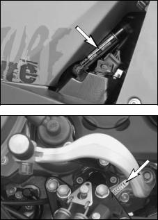
|
SERIAL NUMBER LOCATIONS » |
6 |
Chassis number
The chassis number is located on the right side of the steering head tube and on the type label. Write this number into the relevant area on page 1.
Engine number, engine type
The engine number and engine type are embossed in the engine case near the shift lever.
Write this number into the relevant area on page 1.
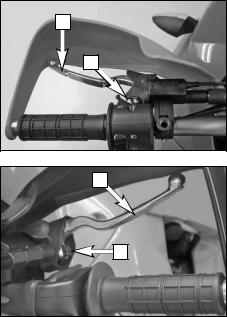
|
OPERATION INSTRUMENTS » |
7 |
Clutch lever
The clutch lever [1] is located on the left side of the handlebar. The adjusting screw [A] is used to change the original position of the clutch lever (see maintenance work on chassis and engine).
The clutch is hydraulically actuated and adjusts itself automatically.
Hand brake lever
The hand brake lever [2] is mounted on the handlebars on the right and actuates the front wheel brake. The adjusting screw [B] can be used to change the basic position of the hand brake lever (see Maintenance).
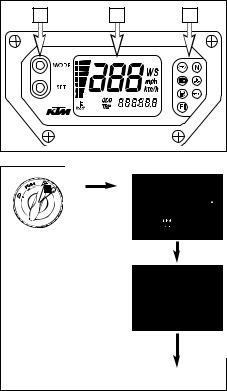
|
OPERATION INSTRUMENTS » |
8 |
Multi-functional digital speedometer
The universal instrument is divided into 3 parts.
Use the MODE and SET [1] button to change the display and the basic settings in the display.
Display [2] shows all of the information that may be of interest to you. 5 display modes can be selected with the MODE button.
The indicator lamps [3] provide additional information on the motorcycle’s running condition.
Display
TEST
When you switch on the ignition, all of the display elements will light up for 1 second for the function test.
WS (wheel size)
The display will change and show the diameter of the front wheel in inches for 1 second (WS = wheel size).
Then the CLOCK mode will be displayed, or the mode that was active when the ignition was switched off.
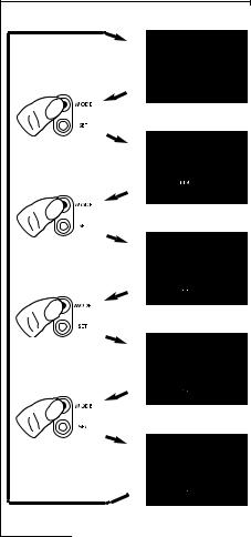
|
OPERATION INSTRUMENTS » |
9 |
CLOCK 
ODO 
TRIP 1 
TRIP 2 
TRIP F 
CLOCK
You will recognize the CLOCK display by the blinking dots between the hours and minutes. It displays the speed, temperature of the cooling liquid and the clock.
To switch to the next display mode, press the MODE button.
ODO
The speed, temperature of the cooling liquid and the total kilometers or miles traveled are shown in the ODO mode.
To switch to the next display mode, press the MODE button.
TRIP 1
The TRIP 1 mode shows the speed, the temperature of the cooling liquid and the trip odometer 1.
To switch to the next display mode, press the MODE button.
TRIP 2
The TRIP 2 mode shows the speed, the temperature of the cooling liquid and the trip odometer 2.
To switch to the next display mode, press the MODE button.
TRIP F
The TRIP F (fuel) mode shows the speed, the temperature of the cooling liquid and the distance traveled since reaching the low-fuel mark (the low-fuel indicator lamp lights up).
To return to the CLOCK mode, press the MODE button.
![]()
|
OPERATION INSTRUMENTS » |
10 |
||||||||
|
Setting |
options in the display |
||||||||
|
1 |
10 sec |
||||||||
|
KILOMETERS OR MILES. |
|||||||||
|
You can have the speed and distance shown in kilometers or miles in the display. The dis- |
|||||||||
|
play can be adapted to the respective country on long-distance trips. |
|||||||||
|
To switch from kilometers to miles, switch on the ignition and press the MODE [1] button |
|||||||||
|
for approx. 10 seconds. The km/h display will switch to mph. The speed and the stored dis- |
|||||||||
|
tances will be converted and displayed in miles. |
|||||||||
|
To return to kilometers, proceed as described above. |
|||||||||
CLOCK
Switch on the ignition and change to the CLOCK mode.
Simultaneously press MODE [1] and SET [2]. The numbers on the clock will start to blink. Use the MODE button to set the hours and the SET button to set the minutes.
The press the MODE and SET buttons simultaneously.
NOTE:
0:00 will be displayed if the clock is not supplied with electricity. This can be caused by a defective fuse or a fault in the board electric system (see Troubleshooting).
TRIP 1
The trip meter 1 runs continuously and counts up to 999.9. It can be used to measure the length of a certain route on a trip or the distance between two refueling stops.
To return the trip meter 1 to zero, switch on the ignition, change to the TRIP 1 mode and press the SET button.
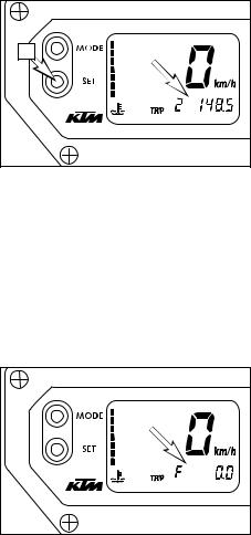
|
OPERATION INSTRUMENTS » |
11 |
RESETTING TRIP 2
The trip meter 2 runs continuously and counts up to 999.9. It can be used similarly to TRIP 1 or together with a switch available as an accessory (see below) for trips according to a roadbook.
To return the trip meter 2 to zero, switch on the ignition, change to the TRIP 2 mode and press the SET button.
NOTE:
A Tripmaster switch (Part no. 582.14.069.044) is available as an accessory and enhances the trip meter 2 functions. You can correct the displayed route by increasing or decreasing in increments of 0.1. For example, if you have taken the wrong road when driving according to a roadbook, you can easily correct the display to correspond to the roadbook again. It can also be used to change the display modes. The switch is mounted on the handlebars so that you can keep your hands on the handlebars.
TRIP F
When the fuel level reaches the reserve mark, the display will automatically switch to TRIP F and begin to count (no matter which display mode was active before). At the same time, the fuel warning lamp will light up. You will still have enough reserve fuel for at least 30 kilometers.
After refueling, it will take approx. 8 minutes for the fuel warning lamp to switch off and for TRIP F to automatically reset to 0 and return to the previous display mode.
NOTE:
Press the SET key for 2 seconds to immediately turn off the fuel warning lamp.
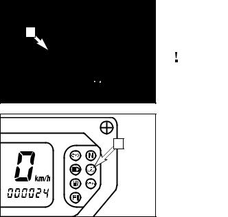
|
OPERATION INSTRUMENTS » |
12 |
|||||||
|
Cooling liquid temperature display |
||||||||
|
120°C |
(248°F) |
The temperature display [1] is shown in 7 bars. The more bars that light up, the hotter the |
||||||
|
1 |
110°C |
(230°F) |
cooling liquid. When the lowest bar lights up, the cooling liquid has reached a temperature |
|||||
|
100°C |
(212°F) |
of approx. 40°C (104°F). When the upper bar lights up 120°C (248°F), all of the bars will |
||||||
|
70°C (158°F) |
start to blink and the red warning lamp [2] will light up. |
|||||||
|
60°C |
(140°F) |
|||||||
|
50°C |
(122°F) |
|||||||
|
40°C |
(104°F) |
Possible causes for an increase in temperature, causing the red warning light for the cool- |
||||||
|
ing liquid temperature to light up: |
||||||||
|
– Driving too slowly and driving with a heavy load at high air temperatures |
|
– |
Not enough cooling liquid in the system |
|
– |
The ventilator on the radiator is not running |
|
– |
Improper use of the clutch when driving slowly |
|
2 |
|
OPERATION INSTRUMENTS » |
13 |
|
Indicator lamps
The green indicator lamp will blink in the blinker rhythm when the blinker is switched on.
NOTE: The indicator lamp will blink faster when a blinker is broken.
The green indicator lamp will light up when the gearbox is in an idling position.
The blue indicator lamp will light up when the high beams are switched on.
The red warning light will light up when the cooling liquid has reached a temperature of approx. 120°C (248°F).
The orange warning light will light up when the fuel level has reached the reserve mark. At the same time the display will automatically change to TRIP F (see TRIP F).
The red warning lamp lights up when the ignition is switched on but the engine is not running. When the engine is started, the warning lamp will go out as soon as the oil pressure is high enough.
The orange warning lamp (fuel injection) briefly lights up when the ignition is switched on. It will go out when the gasoline pressure is high enough.
If this warning lamp lights up while driving, a component in the injection system is defective. The error can be identified by means of a blink code (see Trouble shooting).
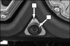
|
OPERATION INSTRUMENTS » |
14 |
|
1 |
ABS warning lamp – models with ABS (antilock brake system) |
|
|
The ABS warning lamp [1] must light up when the ignition is switched on and go out at a |
||
|
speed of approx. 5 KPH after you drive off. If it stays on or lights up while driving, the ABS |
||
|
2 |
is defective. The ABS is no longer active and the wheels can lock when braking. |
|
NOTE:
The brake system will still function but ABS control will no longer be active. Continue to drive carefully and have the ABS checked at an authorized KTM workshop.
NOTE:
The ABS warning lamp can also light up if there is a large deviation between the speed of the front and rear wheel in extreme driving situations, e.g. during a wheelie or if the rear wheel slips when accelerating on loose ground. The ABS will no longer be active and the wheels can lock when braking. To activate the ABS again, stop and switch off the ignition. If the warning lamp goes off again at a speed of approx. 5 KPH after you drive off, the ABS is active and fully operative.
ABS button – models with ABS (antilock brake system)
The ABS button [2] switches off the ABS. To switch off the ABS, stop the motorcycle and press the ABS button for at least 3 seconds with the engine running. Let go of the ABS button as soon as the ABS warning lamp starts blinking fast. The ABS warning lamp will blink slowly to indicate that the ABS is switched off.
To switch the ABS on again, stop and switch off the ignition. The ABS will be active again when you switch on the ignition.
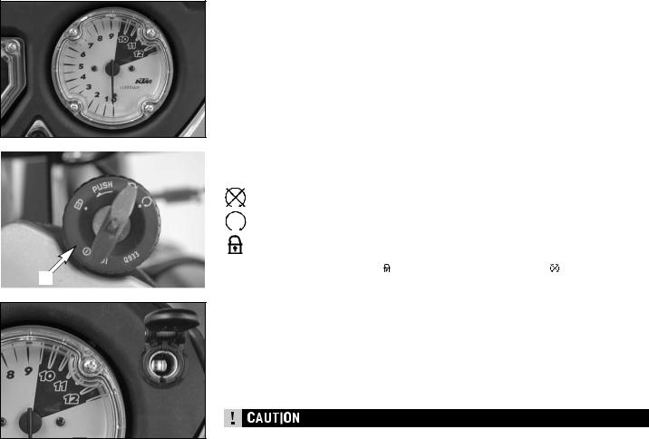
|
OPERATION INSTRUMENTS » |
15 |
Tachometer
The tachometer shows the engine speed in revolutions per minute. Do not run the engine beyond the black mark at 9500 rpm.
The speed limiter will set in at 9600 rpm, drastically reducing the engine power above this rotational speed.
When you switch on the ignition, the indicating needle will move to the black mark and back again.
|
Ignition lock |
|||||
|
The ignition lock [1] has 3 switching positions. |
|||||
|
Ignition off, (engine can’t be started) |
|||||
|
Ignition on, (engine can be started) |
|||||
|
Ignition off, handlebar blocked |
|||||
|
To switch the ignition to position |
turn the ignition key to position |
and firmly press it |
|||
|
1 |
into the lock. Turn the handlebar to the left, then turn the ignition key to the left. |
||||
The ignition key can be withdrawn in position  and
and  .
.
Socket for electric accessories
A socket is provided in the cockpit for electric accessories, e.g. GPS, roadbook, cell phone, etc.
The socket has a 12V voltage and is protected by a 10 A fuse. Do not plug power consumers with a higher requirement into this socket.
Remember that electric accessories will run down the battery.
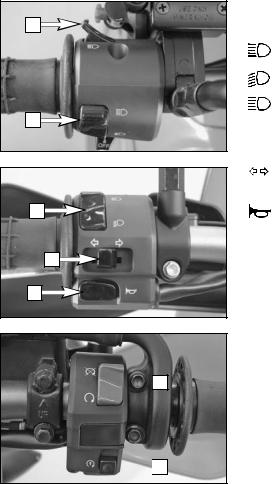
|
OPERATION INSTRUMENTS » |
16 |
Combination switch
The rocker switch LIGHTS [1] actuates the high beam or low beam.
= High-beam light
= Low-beam light
The light signal (high beam) is actuated with button [2].
The indicator switch [3] returns to central position after actuation. Press flasher switch towards switch housing to switch off the flasher.
The horn is sounded with button [4].
Emergency OFF tip switch, starter tip switch
The emergency off switch [5] is provided for emergency situations and should not be used to switch off the engine.
The engine is ready for operation in position  (ignition circuit and starter circuit are switched on).
The engine cannot be started in position  (ignition circuit and starter circuit are interrupted).
 Use the starter tip switch [6] to operate the electric starter.
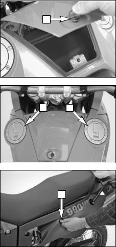
|
OPERATION INSTRUMENTS » |
17 |
Storage compartment
A storage compartment is located under the seat to hold small, frequently used items.
To open, turn the quick release [1] approx. 180° in a counterclockwise direction and lift the cover. To lock, close the cover, insert the quick release in the dolly and turn 180° in a clockwise direction.
Filler caps
The 990 Adventure has 2 separate fuel tanks.
Both filler caps [2] can be locked and are equipped with a tank vent system.
To open, insert the ignition key, turn 45° in a clockwise direction and fold up the filler cap. The ignition key can be pulled out to open the other filler cap. Simply press on the filler cap to close.
Seat lock
The seat is unlocked by inserting the ignition key in the lock [3] on the side and turning the key in a counterclockwise direction. See «Maintenance Work» to remove and remount the seat.
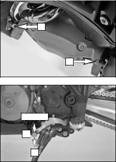
|
OPERATION INSTRUMENTS » |
18 |
||||
|
Fuel taps |
|||||
|
Both fuel taps [1] must be open when the motorcycle is running. The level in the fuel tanks |
|||||
|
is equalized by means of a connecting hose. |
|||||
|
1 |
Only close the fuel taps to remove the tanks. |
||||
1
Shift lever
The shift lever is mounted on the left side of the engine. The position of the gears is shown in the illustration. Neutral, or the idle speed, is located between first and second gear.
2,3,4,5,6
N 
1
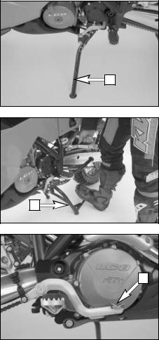
|
OPERATION INSTRUMENTS » |
19 |
Side stand
Fold the side stand [1] forward to the stop with your foot and put the weight of the motorcycle on the stand. Make sure it is standing securely on a firm surface. The side stand is linked to the safety start system; follow the driving instructions.
1
Center stand
The bike is equipped with a side stand and a center stand [2].
2
Foot brake pedal
The foot brake pedal [3] is located in front of the right footrest. Its basic position can be adjusted to your seat position (see maintenance work).
3
![]()
|
OPERATION INSTRUMENTS » |
20 |
Compression damping of fork
The fork’s damping action during compression travel (compression damping) can be adjusted. This allows you adjust the damping behavior to match your driving style and the payload. The adjusting screws [2] are located under the cap [1] on the lower end of the fork legs. More information is provided in the chapter «Adjusting the fork and shock absorber.“
Rebound damping of fork
The fork’s damping action during rebound travel (rebound damping) can also be adjusted. This allows you adjust the damping behavior to match your driving style and the payload. The adjusting screws [3] are located on the upper end of the fork legs.
More information is provided in the chapter «Adjusting the fork and shock absorber.“
Spring preload of the fork
The fork’s preload can be adjusted by means of the adjusting screws [4].
More information is provided in the chapter «Adjusting the fork and shock absorber.“
4
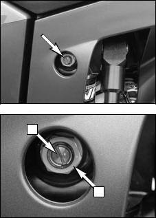
|
OPERATION INSTRUMENTS » |
21 |
Damping action during compression of shock absorber
The shock absorber’s damping action during compression travel (compression damping) can be adjusted. This allows you adjust the shock absorber’s damping behavior to match your driving style and the payload.
The damping rate can be adjusted in the low and high-speed range (Dual Compression Control). The designation low and high-speed refers to the movement of the shock absorber and not to the motorcycle’s driving speed.
The adjusting screw [1] for the low-speed range can be adjusted with a screwdriver.
The adjusting screw [2] for the high-speed range can be adjusted with a 17 mm socket wrench.
More information is provided in the chapter «Adjusting the fork and shock absorber.“
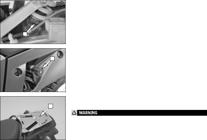
|
OPERATION INSTRUMENTS » |
22 |
Rebound damping of shock absorber
The shock absorber’s damping action during rebound travel (rebound damping) can also be adjusted. This allows you adjust the damping behavior to match your driving style and the payload.
The adjusting screw [1] is located on the bottom of the shock absorber.
More information is provided in the chapter «Adjusting the fork and shock absorber.“
Shock absorber’s preload adjuster
The shock absorber’s preload adjuster is infinitely variable by means of the hand wheel [2]. This allows the shock absorber to be adapted to match your body weight and the payload. The hand wheel can be swung out to make adjustments.
Baggage carrier plate
The base plate for your choice of case system can be attached to the baggage carrier plate [3].
–Do not load more than 8 kg on the trunk carrier rack.
–Observe the baggage manufacturer’s instructions.
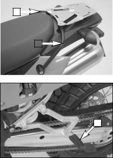
|
OPERATION INSTRUMENTS » |
23 |
|||||||
|
Grips |
||||||||
|
1 |
The passenger can hold on to both grab handles [1]. |
|||||||
|
1 |
||||||||
Footrests
The passenger footrests [2] fold up.
2
Alarm system
An alarm system can be retrofitted. Ask your authorized KTM shop for details.

GENERAL TIPS AND WARNINGS FOR STARTING THE MOTORCYCLE » 24
Instructions for initial operation
–Make sure the work for the „pre-delivery inspection“ was performed by your authorized KTM workshop. The DELIVERY CERTIFICATE and SERVICE MANUAL will be handed over when you pick up your vehicle.
–Read these operating instructions carefully before your first ride.
–Enter the chassis, engine and key numbers on page 1.
–Familiarize yourself with the operating elements.
–Adjust the hand brake lever and foot brake lever to your most comfortable position.
–The motorcycle is equipped with 2 threeway catalysts. Leaded fuel will destroy the catalytic converters. Please use unleaded fuel only.
–Get used to handling the motorcycle on an empty parking lot, before starting on a longer drive. Also try to drive as slowly as possible and in standing position, to improve your feeling for the vehicle.
–Do not drive along off-road tracks which go beyond your abitily and experience.
–Hold the handlebars with both hands and leave your feet on the foot rests while driving.
–Remove your foot from the foot brake lever when you are not braking. If the foot brake lever is not released the brake pads rub continuously and the braking system is overheated.
–Do not make any alterations to the motorcycle and always use ORIGINAL KTM
SPARE PARTS. Spare parts from other manufacturers can impair the safety of the motorcycle.
–New tires have a smooth surface, which means that they must be run in to achieve full grip. For this purpose, ride the motorcycle carefully at moderate speed during the first 200 kilometers with new tires, tilting the vehicle at different angles so that all sections are properly roughened. Tires will not display their full grip characteristics until they are properly run in.
–Motorcycles are sensitive to changes in the weight distribution. Read the section on «Accessories and payload“ when carrying luggage.
–Pay attention to running-in procedure.
Running in the LC8 engine
Even finely machined surfaces of engine parts have rougher surfaces than parts that slide on each other for a long time. Therefore, every engine must be run in. For this reason, do not demand maximum performance from the engine for the first 1000 kilometers (620 miles). The vehicle must be run in at low, changing performance level for the first 1000 km (620 miles). The maximum number of revolutions per minute must not go exceed 6500 rpm. Once you have run your engine in for 1000 km, you may push it to its 9500 rpm limit , i.e. up to the black zone indicated in the tachometer. Exceeding the above listed rotations as well as pushing high rpm when the engine is cold will have an adverse effect on the life of your engine.
–Wear suitable clothing when driving a motorcycle. Clever KTM drivers always wear a helmet, boots, gloves and a jacket, regardless of whether driving all day or just for a short trip. The protective clothing should be brightly colored so that other vehicle can see you as early as possible. Your passenger will also need suitable protective clothing.
–Do not drive after having consumed alcohol.
–Always turn on the light to make sure that other drivers become aware of you as early as possible.
–Drive at a moderate speed for the first few kilometers of each trip to allow the tires to reach the necessary operating temperature. Maximum road grip is assured when the tires are warm.
–The front and rear wheel are allowed to be fitted only with tires that have the same profile type.

GENERAL TIPS AND WARNINGS FOR STARTING THE MOTORCYCLE » 25
–The tires must be designed for a maximum speed of 240 kph (speed symbol V) and must be authorized by KTM.
–Do not exceed the respective maximum speed for tires designed with a speed index of less than «V“ (240 kph). A sticker showing the maximum speed must be affixed to the motorcycle within the driver’s field of vision.
–New wheels have a smooth surface, which means that they must be run in to achieve full grip. For this purpose, ride the motorcycle carefully at moderate speed during the first 200 kilometers with new tires, tilting the vehicle at different angles so that all sections are properly roughened. Tires will not display their full grip characteristics until they are properly run in.
–Wheels with a different rim diameter or other rim width may not be mounted otherwise the vehicle handling will no longer be safe. For models equipped with ABS (antilock brake system), the ABS function is no longer guaranteed.
–Models with ABS: The ABS is designed to be used with the tires authorized by KTM and works best with these tires. The ABS function cannot be guaranteed if other tires are used.
–Models with ABS: an incorrect tire pressure will have an adverse effect on the ABS control and driving stability and will increase the stopping distance.
–Observe the traffic regulations, drive defensively and trying to look ahead as far as possible so that any hazards can be recognized as early as possible.
–The faster you drive, the more sensitive your motorcycle will be to crosswind and changing road conditions. Your motorcycle can easily go out of control at high speeds.
–Choose your driving speed according to the conditions and your driving skills.
–Drive carefully on unknown roads or on unfamiliar trials.
–Renew the vizor on your helmet or the glass of your goggles on time so as to ensure optimum vision in any situation. When light shines directly on scratched visor or goggles, the operator will be blinded.
–Never leave your motorcycle without supervision if the engine is running.
Accessories and payload
Accessory parts and baggage can significantly decrease a motorcycle’s driving stability. Please observe the following warnings.
–Never drive faster than 130 kph (80 mph) if you have mounted accessory parts on your motorcycle. Accessory parts can significantly impair the motorcycle’s handling, especially in the maximum speed range.
–Never drive faster than 130 kph (80 mph) if your motorcycle is loaded with cases or other baggage. They will impair the motorcycle’s handling at higher speeds and can easily cause it to go out of control
–If you have cases mounted, do not exceed the manufacturer’s recommended maximum payload.
–Fasten the baggage close to the center of the motorcycle and distribute the weight evenly on the front and rear wheels and on the left and right.
–Baggage must be securely and adequately fastenend; loose baggage will significantly impair driving safety.
–A high payload will change the motorcycle’s handling and considerably increase the braking distance; adapt your driving speed accordingly.
–Never exceed the maximum permissible laden weight and the axle weights. The maximum permissible laden weight is made up of the following components:
–Motorcycle ready for operation and tank full
–Luggage
–Driver and passenger with protective clothing and helmet
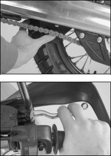
|
DRIVING INSTRUCTIONS » |
26 |
Check the following before each start
When you start, the motorcycle must be in perfect mechanical condition. For safety reasons, you should make a habit of performing an overall check of your motorcycle before each start.
The following checks should be performed:
1FUEL
Check the fuel quantity in the tanks.
2CHAIN
Check the tension and condition of the chain.
A loose chain can fall off the sprockets and a worn-out chain can tear. In both cases this can damage other motorcycle components and cause the motorcycle to go out of control. A chain that is too tight or not greased will cause unnecessary wear to the chain and sprockets.
3TIRES
Check for damaged tires. Tires showing cuts or dents must be replaced. The tread depth must comply with the legal regulations. Also check the air pressure. Insufficient tread and incorrect air pressure deteriorate the driving performance.
4BRAKES
Check correct functioning of the braking system. Check for sufficient brake fluid in the reservoir. The reservoirs have been designed in such a way that brake fluid does not need to be refilled even when the brake pads are worn. If the level of brake fluid falls below the minimum value, this indicates a leak in the braking system or completely worn out brake pads. Arrange for the braking system to be checked by a KTM specialist, as complete failure of the braking system can be avoided.
Also check the state of the brake hose and the thickness of the brake linings.
Check free travel at hand brake lever and foot brake lever.
5CABLES
Check smooth operation of the throttle cables.
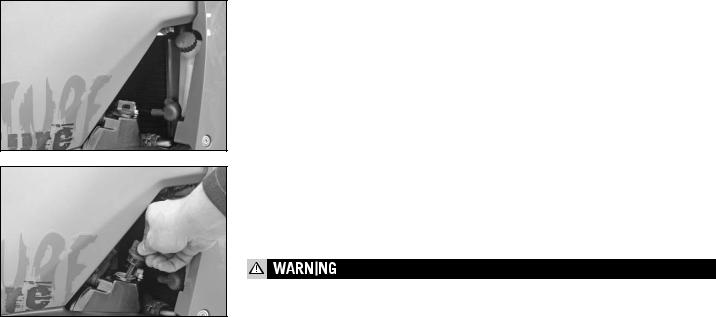
|
DRIVING INSTRUCTIONS » |
27 |
6COOLING FLUID
Check the level of cooling fluid when the engine is cold.
7ELECTRICAL SYSTEM
Start the engine and check the headlight, taillight, brake light, turn signal, indicator lamps and horn for proper functioning.
8CHECK OIL LEVEL
Insufficient oil results in premature wear and consequently to engine damage.
9BAGGAGE, PAYLOAD
Never exceed the maximum total weight (430 kg, 949 lbs) and the motorcycle’s wheel loads. The maximum total weight is comprised of:
–the motorcycle in a running condition and refueled (232 kg, 512 lbs)
–the baggage and accessories
–the driver and passenger with protective gear and helmet
Adjust the tire inflation pressure as well as the preload and damping properties of the fork and shock absorber to the total weight.
Make sure your luggage is correctly fastened before you drive off.
Never drive faster than 130 kph (80 mph) if your motorcycle is loaded with cases or other baggage. They will impair the motorcycle’s handling at higher speeds and can easily cause it to go out of control.
10 REAR MIRROR
Sit on the motorcycle and check the adjustment of the rear mirror.
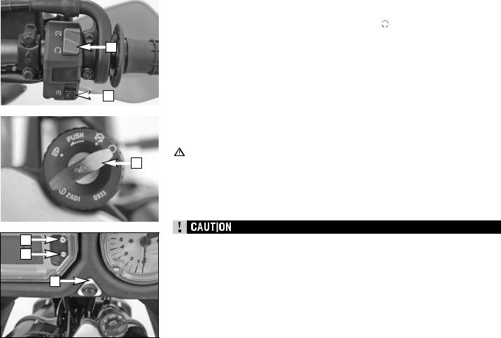
|
DRIVING INSTRUCTIONS » |
28 |
|||||||||
|
Starting the engine |
||||||||||
|
1 |
Switch on emergency OFF switch [1]. |
|||||||||
|
2 |
Switch on ignition (turn ignition key [2] into position ). |
|||||||||
|
NOTE: You will hear the operation of the fuel pump for approx. 2 seconds after switch- |
||||||||||
|
1 |
ing on the ignition. The FI indicator lamp will also light up during this time and the |
|||||||||
|
engine cannot be started. |
||||||||||
|
3 |
NOTE FOR MODELS WITH ABS: |
|||||||||
|
The ABS warning lamp [5] must light up when the ignition is switched on. |
||||||||||
|
4 |
Switch transmission to idle (green indicator lamp N [3] lights up). |
|||||||||
|
6 |
5 |
Do not accelerate; operate starter button [6]. |
||||||||
|
NOTE: If you accelerate during the starting process you will hear a loud, metallic |
||||||||||
|
sound caused by the torque limiter. The torque limiter protects the |
||||||||||
|
components in the starter drive from being damaged. |
||||||||||
|
6 |
The oil pressure warning lamp [4] should go out as soon as the engine is running. |
|||||||||
|
7 |
Take the motorcycle off of the main stand or side stand. |
|||||||||
|
2 |
||||||||||
|
– |
Do not start the engine and allow it to idle in a closed room. Exhaust fumes are poison- |
|||||||||
|
ous and can cause loss of consciousness and death. Always provide adequate ventila- |
||||||||||
|
tion while the engine is running. |
||||||||||
|
– |
Never operate the motorcycle with a run-down battery or without the battery. This can |
|||||||||
|
damage the electronic components or safety equipment in either caseand the motorcy- |
||||||||||
|
cle will no longer be roadworthy. |
||||||||||
–If you accelerate while starting, the engine management will not inject any fuel and the engine will not start. Do not accelerate while starting!
–If the oil pressure warning lamp does not go out as soon as the engine is running, immediately switch off the engine. If the engine is not switched off, engine damage will occur within a short period of time. Check the engine oil level or contact a ktm workshop.
–Maximum period for continuous starting: 5 seconds. Wait at least 5 seconds before trying again.
–Don’t ride your motorcycle with full load and don’t rev engine when cold. Because the piston is warming up faster than the water cooled cylinder, it can cause engine damage. Always let the engine warm up before and refrain from driving with full load until the engine is warm.

|
DRIVING INSTRUCTIONS » |
29 |
IF THE ENGINE IS DOES NOT CRANK WHEN YOU ACTUATE THE STARTER TIP SWITCH:
–whether you accelerated while starting
–the transmission is switched to idle
–Check if the emergency OFF switch is on
–Check if the ignition is on
–the headlight is on (the light is switched off when actuating the starter button)
–If this is not the case, the battery is discharged
–If the lights are on, proceed as described in the „Trouble-shooting“ section or contact a KTM dealer.
IF THE ENGINE CRANKS BUT DOES NOT START, WHEN YOU ACTUATE THE STARTER TIP SWITCH:
–whether you accelerated while starting
–whether the FI indicator lamp is blinking
–if yes, check Troubleshooting — Blink codes table
–Check if sufficient fuel is in the tank
–If this is not the case, refill the tank
–if sufficient fuel is in the tank, proceed as described in the „Troubleshooting“ section or contact a KTM dealer.
NOTE:
This motorcycle is equipped with a safety starting system. The engine can only be started if the transmission is in neutral or the clutch lever is pulled. If the side stand is folded down, the engine can only be started if the trans-
mission is in neutral or the clutch lever is pulled. The engine will stall if a gear is engaged and the clutch lever is released with the side stand folded down.
Starting off
Pull the clutch lever and engage 1st gear. Slowly release the clutch lever while you gently accelerate.
Before you start off, check that the main stand has been swung up fully. If the stand drags on the ground, the motorcycle can go out of control.
Shifting/Riding
You are now in first gear, refered to as the drive or uphill gear. Depending on the conditions (traffic, road gradient, etc.), you can shift to a higher gear. Close throttle, at the same time pull clutch lever and shift to the next higher gear. Let clutch lever go again and carefully open throttle. Do not shift gears and accelerate carefully in curves.
Only accelerate to the extent that road and weather conditions allow. Be especially careful when you accelerate in curves. Abrupt opening of the throttle can cause the motorcycle to go out of control and also increases fuel consumption.
By shifting down, use the brakes if necessary and close throttle at the same time. Pull clutch lever and shift down to the next gear.
Let clutch lever go slowely and open throttle or shift down again.
If the engine is killed f.ex. at a crossing, simply pull the clutch lever and start. It is not necessary to switch the gear to NEUTRAL. Stop immediately if the FI indicator lamp lights up while driving. The FI indicator lamp will start blinking as soon as the transmission is in neutral. The rhythm of the blinking lamp will let you determine the two-digit „blink code“, e.g.:
Blink code 34: FI blinks 3x long, 4x short, pause,
Blink code 06: FI blinks 6x short, pause. The blink code will indicate which component is defective (see Troubleshooting). This makes it possible to pinpoint the defect if a diagnostic tool is unavailable.
–Avoid abrupt load changes while riding around bends and on wet or slippery ground. Otherwise you might easily lose control over your motorcycle.
![]()
|
DRIVING INSTRUCTIONS » |
30 |
–While riding your motorcycle, never switch the ignition lock to positions  And
And  .
.
–Do not try to change the settings of the multi-functional Speedometer while driving. Your attention will be distracted from the traffic and may cause you to lose control of your motorcycle.
–The passenger must hold on to the driver or the grab handle on the baggage carrier during the ride and keep his feet on the passenger footrests.
–Regularly make sure that the baggage and cases are tightly fastened.
–After falling with the motorcycle, check all functions thoroughly before starting up operations again.
–A bent handlebar must always be replaced. Never try to straighten the handlebar because this will cause it to lose its stability.
–High rpm rates when the engine is cold have an adverse effect on the life of your engine. We recommend you run the engine in a moderate rpm range for a few miles giving it a chance to warm up. After that no further precautions in this respect need be taken. The engine has reached operating temperature as soon as the 4th bar on the temperature indicator lights up.
–If the red oil pressure warning lamp lights up while driving, the oil pressure is too low to adequately lubricate the engine.
Stop immediately and switch off the engine. if you continue to drive, engine damage will occur within a short period of time. Check the engine oil level or contact an authorized KTM workshop.
–Never have the throttle wide open when changing down to a lower gear. The engine will overspeed, damaging the valves. In addition, the rear wheel blocks so that the motorcycle can easily get out of control.
–Never use your motorcycle without an air filter. Otherwise dust and dirt may enter the engine and cause increased wear.
–Stop immediately if a perceptible power loss occurs while driving due to a defective ignition caused by a cylinder misfiring or breaking down. If the unburned fuel/air mixture reaches the catalytic converter, it will ignite and the resulting heat will destroy the catalytic converter and the adjoining components.
–the red coolant warning lamp lights up when the coolant temperature has reached 120°c (248°F).
possible causes for the increase in temperature:
–low driving velocity and high load situation in high air temperatures
–level of coolant in the system is insufficient
–fan at radiator is not running
–improper use of the clutch while driving at low velocities
Let the engine cool down. Meanwhile, check whether any cooling liquid is leaking out of the motorcycle. Check the cool-
ing liquid level in the radiator (not only in the compensating tank). — CAUTION SCALDING HAZARD! Do not drive on, until there is sufficient liquid in the coling system.
–In the event that, while riding on your motorcycle, you notice any unusual oper- ation-related noise, stop immediately, turn the engine off, and contact an authorized KTM dealer.
Braking – models
without ABS (antilock brake system)
Close throttle and apply the hand and foot brakes at the same time. Carefully apply the brakes on sandy, wet or slippery surfaces. Always brake with feeling, blocking wheels can cause you to skid or fall. Also change down to lower gears depending on your speed.
Always finish braking before you enter a curve.
When driving downhill, use the braking effect of the engine. Change down one or two gears but do not overspeed the engine. In this way, you will not need to brake so much and the brakes will not overheat.
Braking – models
with ABS (antilock brake system)
Close throttle and apply the hand and foot brakes at the same time. The ABS allows you to apply the full braking force during full braking and with poor road grip on sandy, wet
Specifications:
|
Accompanying Data:
KTM 990 ADVENTURE Motorcycle, Security System PDF Repair Manual (Updated: Friday 13th of January 2023 09:27:33 AM)
Rating: 4.7 (rated by 2 users)
Compatible devices: 65 SX 2017, 990 Adventure USA 2010, Freeride E-XC, Freeride 350 2012, 790 Adventure 2019, RC 390 2016, 1190 RC8 R USA, 690 Duke EU 2014.
Recommended Documentation:
KTM 990 ADVENTURE: Text of Repair Manual
(Ocr-Read Version Summary of Contents, UPD: 13 January 2023)
KTM 990 ADVENTURE: Recommended Instructions
TEW-640MB, DXZ758RMC, MC8088HLC, LGQ9558KQ1, CRC-2400


-
ABCDEFGHLMNPGeneralità 0Description 0Informazioni sul modello 0Model-specific information 0Caratteristiche tecniche 0Specifications 0Uso e manutenzione 0Use and Maintenance operations 0Vestizione 0Fairing 0Comandi — Dispositivi 0Controls — Devices 0Ruote — Sospensioni — Freni 0Wheels — Suspension — Brakes 0Mototelaio 0Frame 0Impianto di alimentazione — Scarico0Fuel system — Exhaust …
SS 800 544
-
DISCLAIMER OF WARRANTY This motorcycle is sold “as is” with all faults, obvious or not. There are no warranties expressed or implied, including any warranty of merchantability and warranty of fitness for any particular purpose. “WARNING” THE COBRA CX50FWE (KING) IS A COMPETITION MODEL ONLY AND IS NOT MANUFACTURED FOR, NOR SHOULD IT BE USED ON PUBL …
CX50FWE 80
-
ATV off roadMXU 500 / MXU 500 IRSOwner’s ManualC 2008 KYMCO. All rights reserved. Printed in Taiwan. www.kymco.comVersion:T200-LAAOCA-US-A5Do not remove this Owner’s Manual from the vehicle. Read thismanual carefully before operating the vehicle as it containsimportant safety information. …
MXU 500 177
-
1This manual should be considered a permanent part of the motorcycle andshould remain with the motorcycle when resold or otherwise transferred toa new owner or operator. The manual contains important safetyinformation and instructions which should be read carefully beforeoperating the motorcycle.*GT250R/S영문내지/060207 2006.2.7 6:33 PM 페이지1 001 PagePro 9100 300DPI 100LPI …
COMET 125 — SERVICE 82
-
Owner’s HandbookRocket 3 TFCThis handbook contains information on the Triumph Rocket 3 TFC motorcycle. Always store this Owner’s Handbook with the motorcycle and refer to it for information whenever necessary.The information contained in this publication is based on the latest information available at the time of printing. Triumph reserves the right to make changes at any …
Rocket 3 TFC 2020 178
-
PREFACEYour motorcycle is conforming to latest (Bharat stage-III norms) regulation for emission, safety & noise levels. We are also using non asbestos brake shoes/pads and engine gaskets which are environment friendly in nature.This booklet is your guide to the basic operation and maintenance of your new Hero MotoCorp IGNITOR. Please take time to read it carefully. As with any fi …
IGNITOR 65
-
Kawasaki KDX200/KDX220 service manual 1995-2006 This manual is comprised of a base manual for the Kawasaki KDX200, along with a supplement manual to make it relevant for the KDX220. Kawasaki service manuals sometimes utilize this build-on-earlier models method when two models are similar to each other. Use the links below or the bookmarks to the left to get to the manual th …
KDX200 236
-
This manual should be considered a permanent part of the motorcycle and should remain with themotorcycle when it is resold.This publication includes the latest production information available before printing.Honda Motor Co., Ltd. reserves the right to make changes at any time without notice and withoutincurring any obligation.No part of this publication may be reproduced without written …
CRF50F 2007 177
-
June 28, 2007 Thanks to James Grooms, editor, Clymer Publications who granted copyright permission to provide access to the out of print manual, Suzuki PE175-400 Singles, 1977-1981. Other Clymer manuals may be viewed at http://clymer.com . …
PE175C 207
Additional Information:
Popular Right Now:
Operating Impressions, Questions and Answers:
-
KTM 990 ADVENTURE — page 1
990 ADVENTURE 990 ADVENTURE S KTM Sportmotorcycle AG A–5230 Mattighofen www.ktm.at 10/2006 FOTO: MITTERBAUER KTM Group Partner ART. NR. 3.211.149 EN OWNER’S MANUAL 2007 …
-
KTM 990 ADVENTURE — page 2
1 All information contained is without obligation. KTM-Sportmotorcycle AG particularly reserves the right to modify any equipment, technical specifications, prices, colors, shapes, materials, services, service work, constructions, equipment and the like so as to adapt them to local conditions or to cancel any of the above items, all without previou …
-
KTM 990 ADVENTURE — page 3
IMPORTANT INFORMATION » 2 INTENDED PURPOSE The KTM 990 Adventure is designed to resist the usual wear and tear of normal use on roads and easy terrain (unpaved roads). OWNER’S MANUAL Carefully read the entire Owner’s Manual before you start riding your motorcycle, even if this will take a little time. It contains use- ful tips and inform …
-
KTM 990 ADVENTURE — page 4
IMPORTANT INFORMATION » W ARRANTY The service work specified in the „Lubrication and Maintenance Schedule“ must be performed by an authorized KTM workshop. This is the only place that has the qualified technicians and the special tools required for the 990 Adventure. Be sure to have the workshop verify all service work carried out in the servi …
-
KTM 990 ADVENTURE — page 5
INDEX » 4 INTRODUCTION . . . . . . . . . . . . . . . . . . . . . . . . . . . . . . . . . .1 IMPOR T ANT INFORMA TION . . . . . . . . . . . . . . . . . . . . . . . . . .2 SERIAL NUMBER LOCA TIONS . . . . . . . . . . . . . . . . . . . . . . . .6 Chassis number . . . . . . . . . . . . . . . . . . . . . . . . . . . . . . . . .6 Engine number , engine …
-
KTM 990 ADVENTURE — page 6
INDEX » 5 Adjusting the spring preload on the fork . . . . . . . . . . . . . . .43 Compression damping of shock absorber . . . . . . . . . . . . . .44 Rebound damping of shock absorber . . . . . . . . . . . . . . . . .45 Adjusting the preload of the shock absorber . . . . . . . . . . . .46 Breathing the fork legs . . . . . . . . . . . . . . . . . …
-
KTM 990 ADVENTURE — page 7
Chassis number The chassis number is located on the right side of the steering head tube and on the type label. Write this number into the relevant area on page 1. Engine number, engine type The engine number and engine type are embossed in the engine case near the shift lever . Write this number into the relevant area on page 1. SERIAL NUMBER LOCA …
-
KTM 990 ADVENTURE — page 8
Clutch lever The clutch lever [1] is located on the left side of the handlebar . The adjusting screw [A] is used to change the original position of the clutch lever (see maintenance work on chassis and engine). The clutch is hydraulically actuated and adjusts itself automatically . Hand brake lever The hand brake lever [2] is mounted on the handleb …
-
KTM 990 ADVENTURE — page 9
Multi-functional digital speedometer The universal instrument is divided into 3 parts. Use the MODE and SET [1] button to change the display and the basic settings in the display . Display [2] shows all of the information that may be of interest to you. 5 display modes can be selected with the MODE button. The indicator lamps [3] provide additional …
-
KTM 990 ADVENTURE — page 10
CLOCK Y ou will recognize the CLOCK display by the blinking dots between the hours and minutes. It displays the speed, temperature of the cooling liquid and the clock. T o switch to the next display mode, press the MODE button. ODO The speed, temperature of the cooling liquid and the total kilometers or miles traveled are shown in the ODO mode. T o …
-
KTM 990 ADVENTURE — page 11
Setting options in the display KILOMETERS OR MILES. Y ou can have the speed and distance shown in kilometers or miles in the display . The dis- play can be adapted to the respective country on long-distance trips. T o switch from kilometers to miles, switch on the ignition and press the MODE [1] button for approx. 10 seconds. The km/h display will …
-
KTM 990 ADVENTURE — page 12
RESETTING TRIP 2 The trip meter 2 runs continuously and counts up to 999.9. It can be used similarly to TRIP 1 or together with a switch available as an accessory (see below) for trips according to a roadbook. T o return the trip meter 2 to zero, switch on the ignition, change to the TRIP 2 mode and press the SET button. NOTE: A T ripmaster switch …
-
KTM 990 ADVENTURE — page 13
OPERATION INSTRUMENTS » 12 120°C (248°F) 110°C (230°F) 100°C (212°F) 70°C (158°F) 60°C (140°F) 50°C (122°F) 40°C (104°F) 1 Cooling liquid temperature display The temperature display [1] is shown in 7 bars. The more bars that light up, the hotter the cooling liquid. When the lowest bar lights up, the cooling liquid has reached a tempe …
-
KTM 990 ADVENTURE — page 14
OPERATION INSTRUMENTS » 13 Indicator lamps The green indicator lamp will blink in the blinker rhythm when the blinker is switched on. NOTE: The indicator lamp will blink faster when a blinker is broken. The green indicator lamp will light up when the gearbox is in an idling position. The blue indicator lamp will light up when the high beams are sw …
-
KTM 990 ADVENTURE — page 15
OPERATION INSTRUMENTS » 14 ABS warning lamp – models with ABS (antilock brake system) The ABS warning lamp [1] must light up when the ignition is switched on and go out at a speed of approx. 5 KPH after you drive off. If it stays on or lights up while driving, the ABS is defective. The ABS is no longer active and the wheels can lock when braking …
-
KTM 990 ADVENTURE — page 16
OPERATION INSTRUMENTS » 15 Tachometer The tachometer shows the engine speed in revolutions per minute. Do not run the engine beyond the black mark at 9500 rpm. The speed limiter will set in at 9600 rpm, drastically reducing the engine power above this rotational speed. When you switch on the ignition, the indicating needle will move to the black m …
-
KTM 990 ADVENTURE — page 17
OPERATION INSTRUMENTS » 16 5 6 2 1 1 3 4 Combination switch The rocker switch LIGHTS [1] actuates the high beam or low beam. = High-beam light = Low-beam light The light signal (high beam) is actuated with button [2] . The indicator switch [3] returns to central position after actuation. Press flasher switch towards switch housing to switch off th …
-
KTM 990 ADVENTURE — page 18
OPERATION INSTRUMENTS » 17 1 2 2 3 Storage compartment A storage compartment is located under the seat to hold small, frequently used items. T o open, turn the quick release [1] approx. 180° in a counterclockwise direction and lift the cover . T o lock, close the cover , insert the quick release in the dolly and turn 180° in a clock- wise direct …
-
KTM 990 ADVENTURE — page 19
OPERATION INSTRUMENTS » 18 1 2,3,4,5,6 N Fuel taps Both fuel taps [1] must be open when the motorcycle is running. The level in the fuel tanks is equalized by means of a connecting hose. Only close the fuel taps to remove the tanks. Shift lever The shift lever is mounted on the left side of the engine. The position of the gears is shown in the ill …
-
KTM 990 ADVENTURE — page 20
OPERATION INSTRUMENTS » 19 1 2 3 Center stand The bike is equipped with a side stand and a center stand [2] . Foot brake pedal The foot brake pedal [3] is located in front of the right footrest. Its basic position can be adjusted to your seat position (see maintenance work). Side stand Fold the side stand [1] forward to the stop with your foot and …
-
KTM 990 ADVENTURE — page 21
OPERATION INSTRUMENTS » 20 1 2 3 3 4 Compression damping of fork The fork’s damping action during compression travel (compression damping) can be adjusted. This allows you adjust the damping behavior to match your driving style and the payload. The adjusting screws [2] are located under the cap [1] on the lower end of the fork legs. More info …
-
KTM 990 ADVENTURE — page 22
OPERATION INSTRUMENTS » 21 1 2 Damping action during compression of shock absorber The shock absorber’s damping action during compression travel (compression damping) can be adjusted. This allows you adjust the shock absorber’s damping behavior to match your driving style and the payload. The damping rate can be adjusted in the low and h …
-
KTM 990 ADVENTURE — page 23
OPERATION INSTRUMENTS » 22 1 2 3 Rebound damping of shock absorber The shock absorber’s damping action during rebound travel (rebound damping) can also be adjusted. This allows you adjust the damping behavior to match your driving style and the payload. The adjusting screw [1] is located on the bottom of the shock absorber . More information …
-
KTM 990 ADVENTURE — page 24
OPERATION INSTRUMENTS » 23 1 1 2 Grips The passenger can hold on to both grab handles [1] . Footrests The passenger footrests [2] fold up. Alarm system An alarm system can be retrofitted. Ask your authorized KTM shop for details. …
-
KTM 990 ADVENTURE — page 25
Instructions for initial operation – Make sure the work for the „pre-delivery inspection“ was performed by your author- ized KTM workshop. The DELIVERY CER- TIFICA TE and SERVICE MANUAL will be handed over when you pick up your vehicle. – Read these operating instructions care- fully before your first ride. – Enter the chassis, engine and …
-
KTM 990 ADVENTURE — page 26
GENERAL TIPS AND WARNINGS FOR STARTING THE MOTORCYCLE » 25 – The tires must be designed for a maxi- mum speed of 240 kph (speed symbol V) and must be authorized by KTM. – Do not exceed the respective maximum speed for tires designed with a speed index of less than «V“ (240 kph). A sticker showing the maximum speed must be affixed to the …
-
KTM 990 ADVENTURE — page 27
Check the following before each start When you start, the motorcycle must be in perfect mechanical condition. For safety reasons, you should make a habit of performing an overall check of your motorcycle before each start. The following checks should be performed: 1 FUEL Check the fuel quantity in the tanks. 2 CHAIN Check the tension and condition …
-
KTM 990 ADVENTURE — page 28
DRIVING INSTRUCTIONS » 27 6 COOLING FLUID Check the level of cooling fluid when the engine is cold. 7 ELECTRICAL SYSTEM Start the engine and check the headlight, taillight, brake light, turn signal, indicator lamps and horn for proper functioning. 8 CHECK OIL LEVEL Insufficient oil results in premature wear and consequently to engine damage. 9 BAG …
-
KTM 990 ADVENTURE — page 29
DRIVING INSTRUCTIONS » 28 1 3 4 5 2 Starting the engine 1 Switch on emergency OFF switch [1] . 2 Switch on ignition (turn ignition key [2] into position ). NOTE: Y ou will hear the operation of the fuel pump for approx. 2 seconds after switch- ing on the ignition. The FI indicator lamp will also light up during this time and the engine cannot be s …
-
KTM 990 ADVENTURE — page 30
IF THE ENGINE IS DOES NOT CRANK WHEN YOU ACTUA TE THE ST ARTER TIP SWITCH: – whether you accelerated while starting – the transmission is switched to idle – Check if the emergency OFF switch is on – Check if the ignition is on – the headlight is on (the light is switched off when actuating the starter button) – If this is not the case, …
-
KTM 990 ADVENTURE — page 31
– While riding your motorcycle, never switch the ignition lock to positions And . – Do not try to change the settings of the multi-functional Speedometer while driv- ing. Y our attention will be distracted from the traffic and may cause you to lose control of your motorcycle. – The passenger must hold on to the driver or the grab handle on th …
-
KTM 990 ADVENTURE — page 32
or slippery surfaces without running a risk of having the wheels lock. – The ABS cannot prevent one or both wheels from losing the road grip if the motorcycle is banked during the braking procedure. Although the wheel will not lock, the centrifugal force will cause the wheel to lose traction and cause the motorcycle to crash despite the ABS. – …
-
KTM 990 ADVENTURE — page 33
Stopping and parking Apply the brakes fully and put the engine into neutral. T o stop the engine, switch off the ignition. Park the motorcycle on a firm surface and lock. – Always park your motorbike on a solid and horizontal surface. – Never leave your motorcycle without supervision as long as the engine is running. – Motorcycle engines prod …
-
KTM 990 ADVENTURE — page 34
NOTE REGARDING THE CENTER ST AND: W e advise the following procedure to place the motorcycle on the center stand as effortlessly as possible: a) press main stand to ground using foot b) put your weight on the stand stabilizer and pull the motorcycle back by the footrest sup- port (see illustration). Make sure that the ground is solid and that your …
-
KTM 990 ADVENTURE — page 35
Fuel In the condition at delivery , the LC8 engine requires unleaded fuel with at least RON 95 (USA = Premium PON 91). If using lower octane fuel, it is easy to change over to the pre-programmed ignition curve for 80 — 94 octane (RON) (see activating the ignition curve for low-octane fuel). After refueling, it will take approx. 8 minutes for the fu …
-
KTM 990 ADVENTURE — page 36
35 …
-
KTM 990 ADVENTURE — page 37
PERIODIC MAINTENANCE SCHEDULE » 990 ADVENTURE 2007 A clean motorcycle can be checked more quickly which saves money! 1st Service after 1000 km every 7500 km or once a year every 15000 km or every 2 years ENGINE Change engine oil and oil filter z z z Clean oil screens of engine and oil tank z z z Clean magnetic drain plugs of engine and oil tank z …
-
KTM 990 ADVENTURE — page 38
PERIODIC MAINTENANCE SCHEDULE » 990 ADVENTURE 2007 A clean motorcycle can be checked more quickly which saves money! 1st Service after 1000 km every 7500 km or once a year every 15000 km or every 2 years ADD-ON-PARTS Check actuating cables for damage, smooth operation, and kink-less arrangement, adjust and lubricate z z z Check fluid level of the …
-
KTM 990 ADVENTURE — page 39
PERIODIC MAINTENANCE SCHEDULE » 990 ADVENTURE 2007 ADDITIONAL SERVICE WORK TO BE PERFORMED UNDER A SEPARATE ORDER at least once a year every 15000 km or every 2 years Perform complete fork maintenance z Perform complete shock absorber maintenance z Clean and lubricate steering-head bearing and sealing elements z T reat the electrical contacts and …
-
KTM 990 ADVENTURE — page 40
PERIODIC MAINTENANCE SCHEDULE » 990 ADVENTURE 2007 VITAL CHECKS AND CARE PROCEDURES TO CONDUCTED BY THE OWNER OR THE MECHANIC before each start after every cleaning every 1000 km or after off road use Check oil level z Check brake fluid level z Check brake pads for wear z Check lighting system for proper operation z Check horn for proper operation …
-
KTM 990 ADVENTURE — page 41
– When cleaning the motorcycle, do not use a high pressure cleaning unit if possible, otherwise water will penetrate the bearing s, elec- tric connectors etc. – Do not use toothed washers or spring washers with the engine fastening screws, as these work into the frame parts and keep wor king loose. Instead, use self-locking nuts. – If you uns …
-
KTM 990 ADVENTURE — page 42
Removing and remounting the seat Insert the ignition key in the seat lock and turn in a counterclockwise direction to unlock the seat. Lift the back of the seat and pull off towards the rear . T o remount, fit the nose [1] of the seat in the front, lower the back while pushing towards the front. Both noses [2] should fit into the frame. Insert the …
-
KTM 990 ADVENTURE — page 43
Adjusting compression damping of fork Hydraulic compression damping determines the reaction when the fork is compressed. The degree of compression can be adjusted with adjusting screws at the bottom of the fork legs. Carefully pry out the protection cover [1] with a screwdriver and remove. T urn the adjusting screws [2] clockwise to increase dampin …
-
KTM 990 ADVENTURE — page 44
Adjusting the spring preload on the fork The fork spring preload can be adjusted by turning the adjusting screws [4] (wrench size 24 mm) ± 5 mm (0,2 in). T urning in a clockwise direction will increase the preload, turning in a counterclockwise direc- tion will decrease the preload. 1 turn will change the preload by 1 mm. Changing the preload will …
-
KTM 990 ADVENTURE — page 45
Compression damping of shock absorber The shock absorber can synchronize the compression damping in the low and high-speed range separately (Dual Compression Control). Low and high speed refers to the movement of the shock absorber during compression and not to the speed of the motorcycle. The low and high-speed technology overlaps. The low-speed s …
-
KTM 990 ADVENTURE — page 46
ST ANDARD ADJUSTMENT HIGH-SPEED: – T urn the adjusting screw in a clockwise direction up to the stop with a socket wrench (wrench size 17 mm). – T urn the adjusting screw in a counterclockwise direction the number of turns specified for the respective type of shock absorber . 990 Adventure . . . . . . . .1.5 turns 990 Adventure S . . . . . .1.5 …
-
KTM 990 ADVENTURE — page 47
Adjusting the preload of the shock absorber The baggage and passenger put the main load on the shock absorber . T o guarantee maxi- mum handling performance, the preload of the shock absorber must be adapted to the load. The preload is hydraulically adjusted by turning the hand wheel [1] . T urning in a clockwise direction will increase the preload …
-
KTM 990 ADVENTURE — page 48
Cleaning the dust sleeves of the telescopic fork The dust-protection bellows [3] are to remove dust and coarse dirt particles from the fork tube. However , after some time, dirt may also get in behind the dust-protection bellows. If this dirt is not removed, the oil sealing rings located behind it may start to leak. Use a screwdriver to lever the d …
-
KTM 990 ADVENTURE — page 49
Correct chain tension Loosen collar nut [1] , loosen counter nuts [2] , and turn right and left adjusting screws [3] equally far . T ighten counter nuts [2] . Before tightening the wheel spindle, verify that the chain adjusters [4] are sitting close to the adjusting screws and that the rear wheel has been aligned with the front wheel. T ighten coll …
-
KTM 990 ADVENTURE — page 50
Chain maintenance Maintenance of the X-ring chain is reduced to a minimum. Rinse off any heavy dirt with plenty of water . Residual used grease must be removed prior to lubrication (Motorex Chain Clean 611). After drying, use a chain spray specially designed for X-ring chains (Motorex Chainlube 622). – No lubrication is allowed to reach the rear …
-
KTM 990 ADVENTURE — page 51
General informations about KTM disc brakes BRAKE CALIPERS: The brake calipers of this series “float“. This means that the brake calipers are not solidly attached to the caliper support. Thus, the brake pads are always in optimum contact with the brake disc. Secure the screws of the caliper support with Loctite 243 and tighten to 25 Nm. For safe …
-
KTM 990 ADVENTURE — page 52
BRAKE FLUID: W e recommend that you use Motorex DOT 5.1 brake fluid when you refill or change the brake fluid. DOT 5. 1 brake fluid has a wet boiling point of 180°C / 356°F (25°C / 45°F higher than DOT 4) and is safer for high performance applications. Brake fluid DOT 5.1 is a poly- ethylene glycol based fluid, amber -colored and can be mixed w …
-
KTM 990 ADVENTURE — page 53
ABS (ANTILOCK BRAKE SYSTEM) 990 ADVENTURE: The ABS is a safety system that prevents the wheels from locking when driving straight ahead without the influence of lateral forces. The ABS unit [1] , consisting of a hydraulic unit, an electronic control unit and the electric pump motor , is located under the seat. Sensors [2] on the front and rear whee …
-
KTM 990 ADVENTURE — page 54
Adjusting of free travel at the hand brake lever Free travel at the hand brake lever may be readjusted by using adjusting screw [1] . In this way , the position of the point of pressure (i.e., the resistance you feel on the hand brake lever when the brake pads are pressed against the brake disc) can be adjusted for any hand size. At the hand brake …
-
KTM 990 ADVENTURE — page 55
Checking rear brake fluid level The brake fluid reservoir for the rear disk brake is combined with the foot brake cylinder and has an inspection window . The brake fluid level should not drop below the «MIN» mark when the motorcycle is in a vertical position. – If the brake fluid level drops below the minimum either the brake system has …
-
KTM 990 ADVENTURE — page 56
55 …
-
KTM 990 ADVENTURE — page 57
Dismounting and mounting the front wheel Jack the motorcycle up at the underride protection until the front wheel no longer touches the ground. Loosen the collar screw [1] and the clamp screws [2] at both fork leg axle passages. Unscrew the collar screw approx. 8 turns, pressing your hand against the collar screw to push the axle passage out of the …
-
KTM 990 ADVENTURE — page 58
T o mount the front wheel, lift the wheel into the fork, slightly pull one brake caliper out and push the tire in between the brake calipers. Insert the brake disks in the brake calipers and mount the axle passage. Mount the collar screw [1] and tighten slightly . T ighten the clamp screws [2] on the right fork leg axle passage (in the direction of …
-
KTM 990 ADVENTURE — page 59
MAINTENANCE WORK ON CHASSIS AND ENGINE » 58 1 2 A 3 A 4 5 Dismounting and mounting the rear wheel NOTE FOR MODELS WITH ABS (ANTILOCK BRAKE SYSTEM): The ABS sensor [6] can be removed to make it easier to dismount and mount the rear wheel. Loosen the HH screw [7] and pull out the ABS sensor . When remounting, apply Loctite 243 (screw retainer) to th …
-
KTM 990 ADVENTURE — page 60
MAINTENANCE WORK ON CHASSIS AND ENGINE » 59 TIRES – AIR PRESSURE front rear Road, driver only 2.4 bar (34psi) 2.6 bar (37psi) Road, with passenger 2.4 bar (34psi) 2.8 bar (40psi) maximum payload 2.4 bar (34psi) 2.8 bar (40psi) Tires, air pressure T ire type, tire condition, and how much air pressure the tires have in them affect the way your mot …
-
KTM 990 ADVENTURE — page 61
MAINTENANCE WORK ON CHASSIS AND ENGINE » 60 Checking spoke tension The correct spoke tension is very important for the stability of the wheels and thus for rid- ing safety . A loose spoke causes the wheel to become unbalanced and before long other spokes will have come loose. Check spoke tension, especially on a new motorcycle, in reg- ular interv …
-
KTM 990 ADVENTURE — page 62
MAINTENANCE WORK ON CHASSIS AND ENGINE » 61 Battery The battery is located in the underride protection in front of the engine and is maintenance- free. It is not necessary to check the electrolyte level or to refill water . Simply keep the bat- tery poles clean and slightly grease them with an acid-free grease if necessary . The charge condition a …
-
KTM 990 ADVENTURE — page 63
Demounting and mounting the battery The battery does not need to be demounted unless the motorcycle is being immobilized. T o demount the battery , remove the screws [1] and fold the underride protection [2] down. Remove the screws [3] and tilt the battery cover [4] to the front. First disconnect the neg- ative pole and then the positive pole. Remo …
-
KTM 990 ADVENTURE — page 64
Charging the battery The battery does not need to be dismounted to charge. Remove the screws [1] and the engine cover [2] . Remove the red protection cover and connect the charging device with the positive terminal post at screw [3] and the negative terminal post at screw [4] . Charge the battery as specified in the following table. Do not exceed t …
-
KTM 990 ADVENTURE — page 65
Main fuse The main fuse protects all of the motorcycle’s current consumers. The main fuse is located in the starter relay under the right engine cowl. Remove the screws [1] and take off the engine cowl [2] . Do not burn yourself on the hot exhaust pipe. Lift the starter relay [3] out of the bracket, remove the cap [4] and check the main fuse [ …
-
KTM 990 ADVENTURE — page 66
Fuses for individual current consumers A fuse box with additional fuses is mounted in the storage compartment to separately pro- tect the current consumers against short circuits. The current consumers and the corresponding fuse capacities are listed on the cover of the fuse box [1] . Spare 10, 15, 25 and 40-ampere fuses [2] are also located next t …
-
KTM 990 ADVENTURE — page 67
Replacing the headlight lamps Remove the 5 screws on the left and right and take off both side covers [1] . Use a screw- driver to detach the retaining tabs [2] , tilt the windshield and headlight forward and pull the connector off the connector support. Place the headlight on a soft pad to keep it from being damaged. Never touch the glass of the b …
-
KTM 990 ADVENTURE — page 68
P ARKING LIGHT BULB [C] : Pull the bulb socket [7] out of the reflector and pull the bulb out of the bulb socket. USA design: The parking light [E] is located in the upper part of the headlight in the USA design. Bulb [F] (see T echnical specifications – Chassis / Lighting) with high and low beams is mounted in the lower part of the headlight. Co …
-
KTM 990 ADVENTURE — page 69
Adjusting the headlight range The payload can make it necessary to correct the headlight range. The headlight range can be adjusted with the adjusting screw [1] . T urning in a clockwise direction will increase the headlight range, turning in a counterclockwise direction will reduce the headlight range. TO CHECK: Make a mark on a light wall behind …
-
KTM 990 ADVENTURE — page 70
Replacing the flasher bulbs Remove the screw on the back of the turn signal, carefully fold the lens [5] towards the motorcycle and remove. Slightly depress the bulb, turn it approx. 30° counterclockwise and pull it out of the socket. T o mount the lamp reverse the worksteps indicated above. MAINTENANCE WORK ON CHASSIS AND ENGINE » 69 5 …
-
KTM 990 ADVENTURE — page 71
Cooling system The water pump in the engine ensures a forced circulation of the cooling liquid. When the engine is cold, the cooling liquid only circulates in the cylinders and cylinder heads. The thermostat will open when the engine reaches approx. 75°C (167°F) and the cooling liquid will also be pumped through the aluminum radiator . Cooling is …
-
KTM 990 ADVENTURE — page 72
A mixture of 50% antifreeze and 50% distilled water is used as the cooling liquid. How ever , the anti-freeze protection must be at least -25° C (-13° F). Aside from antifreezing protec- tion, this mixture also provides great corrosion protection which is why it must not be replaced by pure water . – For the cooling system, use only high-grade …
-
KTM 990 ADVENTURE — page 73
Checking the cooling liquid level in the radiator Remove the 5 screws and the right cover [1] , disconnect the flasher cable and tank ventilation. If possible, always check level of cooling liquid when engine is cold. If you have to open the radiator cap when engine is hot, use a rag to cover the cap and open slowly to release pres- sure. Carefully …
-
KTM 990 ADVENTURE — page 74
Bleeding the cooling system Remove the 5 screws and the left cover [3] , disconnect the flasher cable and tank ventilation. Remove the bleeder screw [4] on the left side of the radiator . T o be able to completely bleed the cooling system, raise the motorcycle approx. 50 cm in the front. Add cooling liquid until it runs out of the discharge opening …
-
KTM 990 ADVENTURE — page 75
Changing the original position of the clutch lever The adjusting screw [1] can be used for individual adjustment of the original position of the clutch lever , thus allowing adjustment to an optimal position for every hand size. T urning the adjusting screw counterclockwise reduces the distance between the clutch lever and the handlebar . T urning …
-
KTM 990 ADVENTURE — page 76
Engine oil Automobile engine oil used to be used for four -stroke motorcycles before there were sepa- rate motorcycle specifications. Different technical developments made it necessary to have a separate specification for four -stroke motorcycles — the JASO T903 MA standard. Whereas car engines require long changing intervals, motorcycle engines re …
-
KTM 990 ADVENTURE — page 77
76 Changing the engine oil and the oil filter, cleaning the oil screen Y ou may only change the engine oil yourself after the warranty period has expired. The war- ranty will become void if you change the oil yourself during the warranty period. NOTE: The LC8 engine has a dry-sump lubrication system. The engine oil is pumped from the oil sump in th …
-
KTM 990 ADVENTURE — page 78
MAINTENANCE WORK ON CHASSIS AND ENGINE » Remove the 6 screws and the cover [4] . Remove the 5 screws, take off the left panel [5] and disconnect the turn signal cable. Close both fuel taps [6] on the connecting line. 4 6 6 5 77 …
-
KTM 990 ADVENTURE — page 79
78 Remove the 3 screws [1] , lift the tank approx. 15 mm and carefully tilt to the side. Disconnect the fuel lines, disconnect the connector for the fuel pump and the pickup cable (fuel level) and set down the tank. Remove the lower screw [2] on the right tank. Remove the HH screws and take off the bat- tery cover [3] . Remove the drain plug [4] on …
-
KTM 990 ADVENTURE — page 80
MAINTENANCE WORK ON CHASSIS AND ENGINE » 79 Carefully pull the oil screen [7] out of the oil tank. Thoroughly clean the drain plugs, the cover and both oil screens. Clean all rubber seal rings and check for damage. Replace if necessary . Mount the oil drain plug on the engine with a new seal ring and tighten to 20 Nm. Slide the oil screen [8] into …
-
KTM 990 ADVENTURE — page 81
MAINTENANCE WORK ON CHASSIS AND ENGINE » 80 Insert a new oil filter [1] in the engine case, grease the O-ring and mount the oil filter cover together with the O-ring. T ighten the screws to 6 Nm. Only use original KTM oil filters. The engine can be damaged if other filters are used. Mount the oil drain plug on the oil tank with a new seal ring and …
-
KTM 990 ADVENTURE — page 82
MAINTENANCE WORK ON CHASSIS AND ENGINE » 81 Add 2.5 liters (0.7 USgal) of fully synthetic engine oil meeting the JASO MA standard (e.g. Motorex Power Synt 4T) and mount the oil dipstick. Start the engine, allow to run warm for 4 minutes and switch off the engine. Remove the oil dipstick and add engine oil up to the MAX mark (approx. 0.5 liters, 0. …
-
KTM 990 ADVENTURE — page 83
Activating the ignition curve for low-octane fuel If you are traveling to a country where fuel having at least 95 octane (RON) is not available, you can easily activate the corresponding ignition curve. A plug and socket connection [1] on a brown/black cable is located near the upper shock absorber holder . If the two connectors are connected to ea …
-
KTM 990 ADVENTURE — page 84
If you have your motorcycle serviced as set forth in this manual, no malfunctioning is to be expected. Nevertheless, if an error does arise, we recommend that you look for the error according to the following chart. Please note that you cannot perform all of the work yourself. If you are not sure, contact your KTM dealer . TROUBLE SHOOTING » 83 TR …
-
KTM 990 ADVENTURE — page 85
TROUBLE SHOOTING » TROUBLE CAUSE REMEDY Engine cranks but doesn’t start. Blown fuse for the fuel pump Clutch not attached to the fuel line The plug and socket connector on the wiring harness is oxidized Error in the injection system A gear is engaged and the side stand is folded down Replace the FUEL PUMP fuse Connect the clutch to the fuel line …
-
KTM 990 ADVENTURE — page 86
TROUBLE SHOOTING » TROUBLE CAUSE REMEDY Engine overheats Defect fan or thermoswitch for fan Air in the cooling system Thermostat defective Contact an authorized KTM workshop. Bleed the cooling system (see Maintenance work) Have the thermostat checked (opening temperature 75°C, 167°F) or replaced; contact an authorized KTM workshop FI lamp is bli …
-
KTM 990 ADVENTURE — page 87
TROUBLE SHOOTING » TROUBLE CAUSE REMEDY Flasher lights, brake light, horn and multi-functional digital speedometer fail Bulb burned out Blown fuse Replace bulb Replace fuse HORN BRAKELIGHT SPEEDO. T ime is not displayed or not cor- rectly displayed Blown fuse, thus no continuous power supply Replace fuse ACC 1 / CLOCK and set the clock. The batter …
-
KTM 990 ADVENTURE — page 88
TROUBLE SHOOTING » 87 The blink code indicates which component is affected by an error . This allows the error to be identified if no diagnosis tool is available. BLINK CODE SIGNAL / COMPONENT ERROR DESCRIPTION ENGINE 12 Coolant temperature sensor Output signal too low /high Continues to run 13 Air temperature sensor Output signal too low /high Co …
-
KTM 990 ADVENTURE — page 89
CLEANING » CONSERVATION FOR WINTER OPERATION » 88 Regular cleaning and paintwork care is part of the maintenance work and helps to maintain the value of your motorcycle. Never clean your motorcycle with a high-pressured cleaner or a high-pressured water jet. The water could otherwise run into the electrical components, connectors, sheathed cables …
-
KTM 990 ADVENTURE — page 90
STORAGE » 89 Should you desire to make a pause over a longer space of time, please observe the following instructions: – Drive the tanks empty to be able to fill up with fresh fuel when starting the motorcycle up again. – Clean motorcycle thoroughly (see chapter: CLEANING) – Change engine oil and oil filter (old engine oil contains aggressiv …
-
KTM 990 ADVENTURE — page 91
TECHNICAL SPECIFICATIONS – CHASSIS » CHASSIS 990 ADVENTURE / 990 ADVENTURE S Frame T ubular chrome-molybdenum-steel space frame Fork WP – Up Side Down 4860 MXMA (Multiadjuster) Wheel travel front ADVENTURE = 210 mm (8.3 in), ADVENTURE S = 265 mm (10.4 in) Rear suspension WP Suspension Progressive Damping System shock absorber with hydraulic pr …
-
KTM 990 ADVENTURE — page 92
TECHNICAL SPECIFICATIONS – CHASSIS » CHASSIS 990 ADVENTURE / 990 ADVENTURE S Lighting flasher 12V 10W (socket BA15s) licens plate illumination 12V 5W (socket W2.1×9,5d) Battery maintenance-free battery 12V 11.2 Ah Steering head angle 63.4° Wheel base 1570 mm (61.8 in) Seat height, unloaded ADVENTURE: 860 mm (33.8 in), ADVENTURE S: 915 mm (36 in …
-
KTM 990 ADVENTURE — page 93
TECHNICAL SPECIFICATIONS – CHASSIS » TIGHTENING TORQUES – CHASSIS HH clamp bolts on top triple clamp M8 20 Nm HH clamp bolts for steering stem M8 20 Nm HH clamp bolts on bottom triple clamp M8 15 Nm AH bolt for handlebar mount M10 20 Nm Collar bolts for handlebar clamps M8 20 Nm HH clamp bolts on fork leg axle passages M8 15 Nm Collar screw on …
-
KTM 990 ADVENTURE — page 94
TECHNICAL SPECIFICATIONS – CHASSIS » TIGHTENING TORQUES – CHASSIS Exhaust nuts on manifold M8 evenly , do not bend sheet metal HH bolts on exhaust suspension M6 Loctite 243 + 12 Nm Spoke nipple M5 5 Nm ± 1 Nm HH nuts on rear sprocket bolts M10x1,25 Loctite 243 + 50 Nm Hexagon nut on engine sprocket M20x1,5 Loctite 243 + sheet retainer + 100 N …
-
KTM 990 ADVENTURE — page 95
TECHNICAL SPECIFICATIONS – ENGINE » ENGINE 990 LC8 Design Liquid-cooled, 2-cylinder 4-stroke engine with 75° V arrangement with balancer shaft and electric starter Displacement 999 cc Bore / Stroke 101/62.4 mm Compression ratio 11.5:1 Fuel unleaded fuel with at least RON 95 (USA: Premium PON 91*) / RON 80 — 94 for other ignition curve) V alve t …
-
KTM 990 ADVENTURE — page 96
TECHNICAL SPECIFICATIONS – ENGINE » ENGINE 990 LC8 Mixture preparation EFI (electronic fuel injection) Ignition system breakerless transistorized electronic ignition system with digital ignition advance Ignition timing Map-controlled via TPS Generator 12V 450W at 6000 rpm Spark plug NGK DCPR 8 E Electrode distance 0.8 mm Cooling system liquid co …
-
KTM 990 ADVENTURE — page 97
HEAD WORD INDEX » 96 ABS button – models with ABS (antilock brake system) . . . . .14 ABS fuses – models with ABS (antilock brake system) . . . . . . .64 ABS warning lamp – models with ABS (antilock brake system) . .14 Accessories and payload . . . . . . . . . . . . . . . . . . . . . . . . . . . .25 Activating the ignition curve for low-octa …
-
KTM 990 ADVENTURE — page 98
HEAD WORD INDEX » 97 Foot brake pedal . . . . . . . . . . . . . . . . . . . . . . . . . . . . . . . . .19 Footrests . . . . . . . . . . . . . . . . . . . . . . . . . . . . . . . . . . . . . . .23 Fuel . . . . . . . . . . . . . . . . . . . . . . . . . . . . . . . . . . . . . . . . . .34 Fuel taps . . . . . . . . . . . . . . . . . . . . . . . . . . …
-
KTM 990 ADVENTURE — page 99
CONSUMER INFORMATION FOR USA ONLY » 98 on frame tube R/S on frame tube R/S on frame tube R/S on frame tube R/S under seat Sticker positions: 2 4 5 6 7 8 9 3 1 …
-
KTM 990 ADVENTURE — page 100
99 [2] T ype label USA [5] Before you go for the first ride [8] T echnical information [7] Noise emission [2] T ype label CAN [6] V ehicle emission [1] EA VP CONSUMER INFORMATION FOR USA ONLY » [4] Fuel level [9] Exhaust system …
-
KTM 990 ADVENTURE — page 101
CONSUMER INFORMATION FOR USA ONLY » 100 REPORTING SAFETY DEFECTS If you believe that your vehicle has a defect which could cause an accident resulting in injury or death, you should immediatel y inform the National Highway T raffic Safety Administration (NHTSA) in addition to notifying KTM North America, Inc. If NHTSA receives similar complaints, …
-
KTM 990 ADVENTURE — page 102
990 ADVENTURE 990 ADVENTURE S KTM Sportmotorcycle AG A–5230 Mattighofen www.ktm.at 10/2006 FOTO: MITTERBAUER KTM Group Partner ART. NR. 3.211.149 DE BEDIENUNGSANLEITUNG 2007 …
owner’s Manuals
PowerWear & PowerParts Manuals
Here is your personal document
If you prefer a printed document to thumb through, or you would like to search for an older document, these are available in the Print on Demand portal.
In the portal, you can find owner’s and repair manuals for a wide variety of models.
You can choose between PDF downloads and printed copies.
To the Print on Demand portal
![]()
Как пользоваться?
Наша цель — обеспечить Вам самый быстрый доступ к руководству по эксплуатации устройства KTM 990 ADVENTURE. Пользуясь просмотром онлайн Вы можете быстро просмотреть содержание и перейти на страницу, на которой найдете решение своей проблемы с KTM 990 ADVENTURE.
Для Вашего удобства
Если просмотр руководства KTM 990 ADVENTURE непосредственно на этой странице для Вас неудобен, Вы можете воспользоваться двумя возможными решениями:
- Полноэкранный просмотр -, Чтобы удобно просматривать инструкцию (без скачивания на компьютер) Вы можете использовать режим полноэкранного просмотра. Чтобы запустить просмотр инструкции KTM 990 ADVENTURE на полном экране, используйте кнопку Полный экран.
- Скачивание на компьютер — Вы можете также скачать инструкцию KTM 990 ADVENTURE на свой компьютер и сохранить ее в своем архиве. Если ты все же не хотите занимать место на своем устройстве, Вы всегда можете скачать ее из ManualsBase.
Руководство по эксплуатации KTM 990 ADVENTURE
Печатная версия
Многие предпочитают читать документы не на экране, а в печатной версии. Опция распечатки инструкции также предусмотрена и Вы можете воспользоваться ею нажав на ссылку, находящуюся выше — Печатать инструкцию. Вам не обязательно печатать всю инструкцию KTM 990 ADVENTURE а только некоторые страницы. Берегите бумагу.
Резюме
Ниже Вы найдете заявки которые находятся на очередных страницах инструкции для KTM 990 ADVENTURE. Если Вы хотите быстро просмотреть содержимое страниц, которые находятся на очередных страницах инструкции, Вы воспользоваться ими.
Краткое содержание
Скачавание инструкции
| # | Руководство по эксплуатации | Категория | Скачать |
|---|---|---|---|
| 1 | KTM 1190 RC8 AUS/UK | Motorcycle | 86 |
| 2 | KTM 1190 RC8 | Motorcycle | 221 |
| 3 | KTM 1190 RC8 FR | Motorcycle | 24 |
| 4 | KTM 1190 RC8 JP | Motorcycle | 53 |
| 5 | KTM 125 EXC, EXC SIX DAYS, 200 XC, XC-W, EXC, 250 XC, XC-W, EXC, EXC SIX DAYS, 300 XC, XC-W, EXC-E, EXC-E SIX DAYS | Motorcycle | 946 |
KTM 990 Adventure Service Repair Manuals on Motor Era

Motor Era offers service repair manuals for your KTM 990 Adventure — DOWNLOAD your manual now! KTM 990 Adventure service repair manuals
Complete list of KTM 990 Adventure motorcycle service repair manuals:
KTM 950 990 Adventure 2003-2007 Workshop Service Repair Manual
KTM 990 Adventure 2003-2007 Workshop Service Repair Manual
KTM 950 990 Adventure 2003-2007 Service Repair Manual
KTM 950 990 Adventure 2003-2007 Factory Repair Manual PDF
KTM 950 990 Adventure 2003-2007 Repair Service Manual PDF
KTM 950 990 Adventure 2003-2007 Service Repair Manual
KTM 950 990 Adventure 2003-2006 Service Repair Manual
KTM 950 990 Adventure 2003-2006 Repair Service Manual PDF
KTM 950 990 Adventure 2003-2006 Service Repair Manual PDF
KTM 950 990 Adventure 2003-2006 Service Repair Manual
KTM 950 990 Adventure 2003-2007 All Service Repair Manual
KTM 950 990 Adventure Engine 2003-2006 Service Repair Manual
KTM 950 990 Adventure Engine 2003-2007 Service Repair Manual
KTM 990 Adventure 2003-2007 All Service Manual Repair
KTM 990 Adventure 2003-2007 Factory Service Repair Manual
KTM 950 990 Adventure 2003-2007 Workshop Service Manual
KTM 950 990 Adventure 2003-2007 Full Service Repair Manual
KTM 950 990 Adventure 2003 Full Service Repair Manual
KTM 950 990 Adventure 2004 Full Service Repair Manual
KTM 950 990 Adventure 2005 Full Service Repair Manual
KTM 950 990 Adventure 2006 Full Service Repair Manual
KTM 950 990 Adventure 2007 Full Service Repair Manual
KTM 950 990 Adventure 2003-2007 WSM Service Manual Repair
KTM 990 Adventure 2003-2007 Full Service Repair Manual
KTM 990 Adventure 2003-2007 WSM Service Manual Repair
KTM 990 Adventure 2003-2007 Workshop Service Manual Repair
KTM 950 990 Adventure 2003-2007 Workshop Service Manual
KTM 990 Adventure 2003-2007 Workshop Repair Service Manual
KTM 990 Adventure 2003-2007 Workshop Service Manual
KTM 950 990 Adventure 2003 Repair Service Manual
KTM 950 990 Adventure 2004 Repair Service Manual
KTM 950 990 Adventure 2005 Repair Service Manual
KTM 950 990 Adventure 2006 Repair Service Manual
KTM 950 990 Adventure 2007 Repair Service Manual
KTM 950 990 Adventure 2003-2007 Repair PDF Service Manual
KTM 990 Adventure 2003-2007 Repair Service Manual
KTM 950 990 ADVENTURE, 990 Super Duke R, Supermoto R Super Enduro 2003 2004 2005 2006 2007 2008 Workshop Service Repair Manual
KTM 950 990 ADVENTURE 2003-2007 FULL SERVICE REPAIR MANUAL
KTM 990 ADVENTURE 2003-2007 SERVICE MANUAL
2003-2008 KTM 950 990 ADVENTURE, 990 Super Duke / R, Supermoto / R Super Enduro Workshop Service Repair Manual Download 2003 2004 2005 2006 2007 2008
2003-2007 Ktm 950 Adventure, 990 Adventure, 990 Super Duke, 950 Supermoto, 950 Super Enduro Engine Workshop Repair Service Manual
KTM 950 990 Adventure 2003-2007 Repair Service Manual
KTM 950 990 ADVENTURE 2003-2007 Workshop Service Manual
KTM 950 990 ADVENTURE 2003-2007 Service Repair Manual
950 990 ADVENTURE Super Supermoto SuperEnduro service manual
KTM 950-990 Adventure 2003 2004 2005 2006 Service Repair Manual
2003-2006 KTM 950 ADVENTURE, 990 ADVENTURE, 990 SUPER DUKE, 950 SUPERMOTO, 950 SUPER ENDURO Engine Service Repair Workshop Manual Download
KTM 990 Adventure 2003-2007 Service Repair Manual
2003-2005 Ktm 950 Adventure,990 Super Duke Engine Workshop Service Repair Manual
2003-2007 KTM 950 ADVENTURE, 990 ADVENTURE, 990 SUPER DUKE, 950 SUPERMOTO, 950 SUPER ENDURO Motorcycle Workshop Repair Service Manual
KTM 2003-2007 950 ADVENTURE, 990 ADVENTURE, 990 SUPER DUKE, 950 SUPERMOTO, 950 SUPER ENDURO WORKSHOP REPAIR & SERVICE MANUAL #❶ QUALITY!
2003,2004,2005,2006,2007,2008 KTM 950 ,990 ENGINE Service REPAIR MANUAL
KTM 2003,2004,2005,2006,2007 950 ADVENTURE,990 ADVENTURE,990 SUPER DUKE,950 SUPERMOTO,950 SUPER ENDURO Engine Service Repair Manual
2003-2006 KTM 950 ADVENTURE, 990 ADVENTURE, 990 SUPER DUKE, 950 SUPERMOTO, 950 SUPER ENDURO Workshop Repair Service Manual BEST DOWNLOAD
KTM 950 ,990 ENGINE REPAIR MANUAL 2003,2004,2005,2006,2007
KTM 2003,2004,2005,2006, 950 & 990 ADVENTURE, 990 SUPER DUKE, 950 SUPERMOTO, 950 SUPER ENDURO,LC8 Engine Service Repair Manual
KTM 950 990 LC8 Egine Repair Manual 2003-2007
2003-2006 KTM 950 ADVENTURE, 990 ADVENTURE, 990 SUPER DUKE, 950 SUPERMOTO, 950 SUPER ENDURO Engine Workshop Service Repair Manual Download
2003-2007 Ktm 950 990 Super Duke Lc8 Service Repair Manual
KTM 2003-2005 950 ADVENTURE, 2003-2005 990 SUPER DUKE WORKSHOP REPAIR & SERVICE MANUAL #❶ QUALITY!
2003-2005 KTM 950 ADVENTURE,990 SUPER DUKE Engine Service Repair Workshop Manual Download
KTM 950 990 Adventure, 990 Super Duke R, Supermoto R Super Enduro Complete Workshop Service Repair Manual 2003 2004 2005 2006 2007 2008
KTM 950 990 Adventure, 990 Super Duke R, Supermoto R Super Enduro 2003-2008 Service Repair Workshop Manual Download Pdf
2006 KTM 990 ADVENTURE / 990 ADVENTURE S MOTORCYCLE OWNER’S MANUAL
2007 KTM 990 ADVENTURE / 990 ADVENTURE S MOTORCYCLE OWNER’S MANUAL
2008 KTM 990 ADVENTURE / 990 ADVENTURE S MOTORCYCLE OWNER’S MANUAL
KTM 950/990 ADVENTURE, 990 SUPER DUKE, 950 SUPERMOTO, 950 SUPER ENDURO ENGINE SERVICE REPAIR MANUAL 2003 2004 2005 2006 DOWNLOAD
KTM 950/990 ADVENTURE, 990 SUPER DUKE, 950 SUPERMOTO, 950 SUPER ENDURO ENGINE SERVICE REPAIR MANUAL 2003 2004 2005 2006 2007 DOWNLOAD
KTM 950/990 ADVENTURE, 990 SUPER DUKE, 950 SUPERMOTO, 950 SUPER ENDURO ENGINE SERVICE & REPAIR MANUAL (2003 2004 2005 2006) — DOWNLOAD!
KTM 950/990 ADVENTURE, 990 SUPER DUKE, 950 SUPERMOTO, 950 SUPER ENDURO ENGINE SERVICE & REPAIR MANUAL (2003 2004 2005 2006 2007) — DOWNLOAD!
KTM 950 990 Adventure Super Duke Super Moto Complete Workshop Service Repair Manual 2000 2001 2002 2003 2004 2005 2006 2007
2006 Ktm 990 Adventure / 990 Adventure S Owners Manual
2007 Ktm 990 Adventure / 990 Adventure S Owners Manual
2003-2006 KTM 950 990 LC8 Workshop Service and Repair manual (Free Preview)
KTM 950 Adventure, 990 Super Duke Motorcycle Workshop Service Repair Manual 2003-2005 (En-De-Fr-It-Es) (203MB, 2,500+ Pages, Searchable, Printable, Bookmarked, iPad-ready PDF)
2008 Ktm 990 Adventure / 990 Adventure S Owners Manual
2003, 2004, 2005, 2005, 2006 KTM 950 ADVENTURE, 990 ADVENTURE, 990 SUPER DUKE, 950 SUPERMOTO, 950 SUPER ENDURO Motorcycle Workshop Service Manual
KTM 950 ADVENTURE / 990 SUPER DUKE ENGINE SERVICE REPAIR MANUAL 2003 2004 2005 DOWNLOAD
KTM 950 ADVENTURE / 990 SUPER DUKE ENGINE SERVICE & REPAIR MANUAL (2003 2004 2005) — DOWNLOAD!
KTM 950 ADVENTURE / 990 SUPER DUKE 2003-2005 Factory Manual
2003-2007 KTM 950 990 Super Duke RA LC8 Service Repair Manual DOWNLOAD 2003 2004 2005 2006 2007
KTM 950 990 ADVENTURE DIGITAL WORKSHOP REPAIR MANUAL 2007
KTM 950 990 ADVENTURE 2003-2006 BIKE WORKSHOP SERVICE MANUAL
2003-06 KTM 950 990 SERVICE REPAIR MANUAL
KTM 950 990 ADVENTURE 2003-2006 BIKE SERVICE REPAIR MANUAL
KTM 950-990 Owners manual
950,990 , 2003-07 KTM ENGINE REPAIR MANUAL
2003-2006 KTM LC8 Service Repair Manual Download
KTM 950 ADVENTURE,990 ADVENTURE,990 SUPER DUKE,950 SUPERMOTO,950 SUPER ENDURO Engine 2003 2004 2005 2006 2007 Service Repair Manual
KTM 950, 990 ADVENTURE, 990 SUPER DUKE, 950 SUPERMOTO, 950 SUPER ENDURO 2003 2004 2005 2006 Motorcycle Workshop Repair Service Manual
2003-2006 KTM 950 990 LC8 Service Repair Manual DOWNLOAD
KTM 950 990 ADVENTURE 2003-2006 BIKE SERVICE REPAIR MANUAL
KTM-LC8 950/990 Adventure-Super Duke 2003-2007 Repair Manual
KTM 950 — 990 Adventure 2003-2006 Service Repair Manual
KTM MOTORBIKE ALL MODELS WORKSHOP REPAIR SERVICE MANUAL
KTM 950-990 ADVENTURE SUPER DUKE 2003-2005 ONWERS,REPIR,CHOCK, FORK MANUAL D-I-E-GB
KTM 950 990 ADVENTURE SUPERDUKE SUPERMOTO FULL SERVICE & REPAIR MANUAL 2003-2007
KTM 950 990 ADVENTURE FULL SERVICE & REPAIR MANUAL 2000-2007
KTM 950 990 ADVENTURE SERVICE REPAIR PDF MANUAL DOWNLOAD 2007
KTM 950 990 ADVENTURE SERVICE REPAIR MANUAL 2007
KTM 990 ADVENTURE S REPLACEMENT PARTS MANUAL 2008
KTM 990 ADVENTURE R REPLACEMENT PARTS MANUAL 2010
KTM 990 ADVENTURE R REPLACEMENT PARTS MANUAL 2009
KTM 950 990 ADVENTURE 2003-2006 BIKE WORKSHOP REPAIR MANUAL
Loading…
OWNER’S MANUAL 2007
990 ADVENTURE
990 ADVENTURE S
ART. NR. 3.211.149 EN
We would like to congratulate you on your purchase of a KTM motorcycle. You are now the owner of a state-of-the-art sport motorcycle that guarantees to bring you lots of fun and enjoyment, provided that you clean and maintain it appropriately.
Please insert the serial numbers of your motorcycle in the boxes below:
|
Frame number |
Stamp of dealer |
Engine number
Key number
All information contained is without obligation. KTM-Sportmotorcycle AG particularly reserves the right to modify any equipment, technical specifications, prices, colors, shapes, materials, services, service work, constructions, equipment and the like so as to adapt them to local conditions or to cancel any of the above items, all without previous announcement and without giving reasons. KTM may stop manufacturing certain models without previous notice. KTM shall not be held liable for any deviations of availability and/or ability to deliver, illustrations, descriptions, printing and/or other errors. The illustrated models partly contain extra equipment, which is not applied to standard models.
© 2006 by KTM-SPORTMOTORCYCLE AG, Mattighofen AUSTRIA; All rights reserved; Reprint, also in extracts, with written allowance of KTM-SPORTMOTORCYCLE AG, Mattighofen only.
COMSUMER INFORMATION FOR AUSTRALIA ONLY Tampering with noise control system prohibited Owners are warned that the law may prohibit:
(a)The removal or rendering inoperative by any person other than for purposes of maintenance, repair or replacement, of any device or element of design incorporated into any new vehicle for the purpose of noise control prior to its sale or delivery to the ultimate purchaser or while it is in use; and
(b)the use of the vehicle after such device or element of design has been removed or rendered inoperative by any person.
In accordance with the international quality management ISO 9001 standard, KTM uses quality assurance processes that lead to the highest possible product quality.
|
IMPORTANT INFORMATION » |
2 |
INTENDED PURPOSE
The KTM 990 Adventure is designed to resist the usual wear and tear of normal use on roads and easy terrain (unpaved roads).
OWNER’S MANUAL
Carefully read the entire Owner’s Manual before you start riding your motorcycle, even if this will take a little time. It contains useful tips and information on the best way to handle the motorcycle and how to protect yourself from injuries. The Manual also contains important information on service and maintenance. In your own interest, pay particular attention to the information marked as follows:
–Ignoring these instructions, can endanger your body and your life.
–Ignoring these instructions could cause damage to parts of your motorcycle or that the motor-cycle is not road-safe anymore.
The Owner’s Manual corresponded to the latest information available for this model series at the time it was printed. Minor deviations resulting from enhancements to the motorcycle design cannot be entirely precluded. The Owner’s Manual is an integral part of the motorcycle and must be handed over to the new owner when the motorcycle is sold.
SERVICE
Observance of the service, maintenance and operating instructions for the engine and chassis specified in the Owner’s Manual is a prerequisite for faultless operation and the avoidance of premature wear. Please observe the prescribed breaking-in periods, inspection intervals and service intervals. Strict observance will significantly prolong the service life of your motorcycle.
Use of the motorcycle under extreme conditions, e.g. on extremely muddy and wet terrain, can lead to higher than average wear on components such as the drive train or the brakes. In this case it may become necessary to service or replace wear parts before the service limit specified in the maintenance schedule has been reached.
|
IMPORTANT INFORMATION » |
3 |
WARRANTY
The service work specified in the „Lubrication and Maintenance Schedule“ must be performed by an authorized KTM workshop. This is the only place that has the qualified technicians and the special tools required for the 990 Adventure. Be sure to have the workshop verify all service work carried out in the service manual to avoid losing your right to claim under the warranty.
The warranty or guarantee shall become void for damage and consequential damage caused by manipulations or conversions to the motorcycle.
AUTOMOTIVE FLUIDS
The fuels, lubricants and liquids specified in the Owner’s Manual or automotive fluids with equivalent specifications must be used in accordance with the maintenance schedule.
SPARE PARTS, ACCESSORIES
For your own safety, only use spare parts and accessories approved by KTM. KTM shall not assume any liability for other products or consequential damage resulting from the use of such products.
ENVIRONMENT
Motorcycle driving is a wonderful sport and we hope that you will be able to enjoy it to the full. It may, however, involve potential problems for the environment or lead to conflicts with others. These problems or conflicts can be avoided if the motorcycle is used responsibly. To safeguard the future of motorcycle sports, make sure that you use the motorcycle in accordance with the law, show that you are environmentally conscious and respect the rights of others.
Enjoy driving your motorcycle !
KTM SPORTMOTORCYCLE AG 5230 MATTIGHOFEN, AUSTRIA
|
INTRODUCTION . . . . . . . . . . . . . . . . . . . . . . . . . . . . . . |
. . . .1 |
|
IMPORTANT INFORMATION . . . . . . . . . . . . . . . . . . . . . . |
. . . .2 |
|
SERIAL NUMBER LOCATIONS . . . . . . . . . . . . . . . . . . . . . |
. . .6 |
|
Chassis number . . . . . . . . . . . . . . . . . . . . . . . . . . . . . . |
. . .6 |
|
Engine number, engine type . . . . . . . . . . . . . . . . . . . . . |
. . .6 |
|
OPERATION INSTRUMENTS . . . . . . . . . . . . . . . . . . . . . . |
. . .7 |
|
Clutch lever . . . . . . . . . . . . . . . . . . . . . . . . . . . . . . . . |
. . .7 |
|
Hand brake lever . . . . . . . . . . . . . . . . . . . . . . . . . . . . . |
. . .7 |
|
Multi-functional digital speedometer . . . . . . . . . . . . . . |
. . .8 |
|
Display . . . . . . . . . . . . . . . . . . . . . . . . . . . . . . . . . . . . |
. . .8 |
|
Setting options in the display . . . . . . . . . . . . . . . . . . . . |
. .10 |
|
Cooling liquid temperature display . . . . . . . . . . . . . . . . |
. .12 |
|
Indicator lamps . . . . . . . . . . . . . . . . . . . . . . . . . . . . . . |
. .13 |
|
ABS warning lamp – models with ABS |
|
|
(antilock brake system) . . . . . . . . . . . . . . . . . . . . . . . . |
. .14 |
|
ABS button – models with ABS (antilock brake system) |
. . .14 |
|
Tachometer . . . . . . . . . . . . . . . . . . . . . . . . . . . . . . . . . |
. .15 |
|
Ignition lock . . . . . . . . . . . . . . . . . . . . . . . . . . . . . . . . |
. .15 |
|
Combination switch . . . . . . . . . . . . . . . . . . . . . . . . . . . |
. .16 |
|
Emergency OFF tip switch, starter tip switch . . . . . . . . . |
. .16 |
|
Storage compartment . . . . . . . . . . . . . . . . . . . . . . . . . . |
. .17 |
|
Filler caps . . . . . . . . . . . . . . . . . . . . . . . . . . . . . . . . . . |
. .17 |
|
Seat lock . . . . . . . . . . . . . . . . . . . . . . . . . . . . . . . . . . |
. .17 |
|
Fuel taps . . . . . . . . . . . . . . . . . . . . . . . . . . . . . . . . . . |
. .18 |
|
Shift lever . . . . . . . . . . . . . . . . . . . . . . . . . . . . . . . . . . |
. .18 |
|
Side stand . . . . . . . . . . . . . . . . . . . . . . . . . . . . . . . . . |
. .19 |
|
Center stand . . . . . . . . . . . . . . . . . . . . . . . . . . . . . . . . |
. .19 |
|
Foot brake pedal . . . . . . . . . . . . . . . . . . . . . . . . . . . . . |
. .19 |
|
Compression damping of fork . . . . . . . . . . . . . . . . . . . . |
. .20 |
|
Rebound damping of fork . . . . . . . . . . . . . . . . . . . . . . . |
. .20 |
|
Spring preload of the fork . . . . . . . . . . . . . . . . . . . . . |
. . . .20 |
|
Damping action during compression of shock absorber |
. . . .21 |
|
Rebound damping of shock absorber . . . . . . . . . . . . . . |
. . .22 |
|
Shock absorber’s preload adjuster . . . . . . . . . . . . . . . . |
. . .22 |
|
Baggage carrier plate . . . . . . . . . . . . . . . . . . . . . . . . . |
. . .22 |
|
Grips . . . . . . . . . . . . . . . . . . . . . . . . . . . . . . . . . . . . |
. . .23 |
|
Footrests . . . . . . . . . . . . . . . . . . . . . . . . . . . . . . . . . |
. . .23 |
|
Alarm system . . . . . . . . . . . . . . . . . . . . . . . . . . . . . . |
. . .23 |
|
GENERAL TIPS AND WARNINGS FOR STARTING |
|
|
THE MOTORCYCLE . . . . . . . . . . . . . . . . . . . . . . . . . . . . |
. . .24 |
|
Instructions for initial operation . . . . . . . . . . . . . . . . . |
. . .24 |
|
Running in the LC8 engine . . . . . . . . . . . . . . . . . . . . . |
. . .24 |
|
Accessories and payload . . . . . . . . . . . . . . . . . . . . . . . |
. . .25 |
|
DRIVING INSTRUCTIONS . . . . . . . . . . . . . . . . . . . . . . . |
. . .26 |
|
Check the following before each start . . . . . . . . . . . . . |
. . .26 |
|
Starting the engine . . . . . . . . . . . . . . . . . . . . . . . . . . |
. . .28 |
|
Starting off . . . . . . . . . . . . . . . . . . . . . . . . . . . . . . . . |
. . .29 |
|
Shifting/Riding . . . . . . . . . . . . . . . . . . . . . . . . . . . . . |
. . .29 |
|
Braking – models without ABS (antilock brake system) |
. . . .30 |
|
Braking – models with ABS (antilock brake system) . . . |
. . .30 |
|
Switching off the ABS . . . . . . . . . . . . . . . . . . . . . . . . |
. . .31 |
|
Stopping and parking . . . . . . . . . . . . . . . . . . . . . . . . . |
. . .32 |
|
Fuel . . . . . . . . . . . . . . . . . . . . . . . . . . . . . . . . . . . . . |
. . .34 |
|
PERIODIC MAINTENANCE SCHEDULE . . . . . . . . . . . . . . |
. . .36 |
|
MAINTENANCE WORK ON CHASSIS AND ENGINE . . . . . |
. . .40 |
|
Removing and remounting the seat . . . . . . . . . . . . . . . |
. . .41 |
|
Tool set . . . . . . . . . . . . . . . . . . . . . . . . . . . . . . . . . . |
. . .41 |
|
Adjusting the fork and shock absorber . . . . . . . . . . . . |
. . .42 |
|
Adjusting compression damping of fork . . . . . . . . . . . . |
. . .42 |
|
Adjusting rebound damping of fork . . . . . . . . . . . . . . . |
. . .42 |
|
Adjusting the spring preload on the fork . . . . . . . . . . . . . . |
.43 |
|
Compression damping of shock absorber . . . . . . . . . . . . . . |
44 |
|
Rebound damping of shock absorber . . . . . . . . . . . . . . . . . |
45 |
|
Adjusting the preload of the shock absorber . . . . . . . . . . . . |
46 |
|
Breathing the fork legs . . . . . . . . . . . . . . . . . . . . . . . . . . |
46 |
|
Cleaning the dust sleeves of the telescopic fork . . . . . . . . . |
47 |
|
Checking the chain tension . . . . . . . . . . . . . . . . . . . . . . . |
47 |
|
Correct chain tension . . . . . . . . . . . . . . . . . . . . . . . . . . . . |
48 |
|
Chain maintenance . . . . . . . . . . . . . . . . . . . . . . . . . . . . . |
49 |
|
Checking the chain for wear . . . . . . . . . . . . . . . . . . . . . . . |
49 |
|
General informations about KTM disc brakes . . . . . . . . . . . |
50 |
|
Adjusting of free travel at the hand brake lever . . . . . . . . . . |
53 |
|
Checking of brake fluid level — front brake . . . . . . . . . . . . . |
53 |
|
Checking the front brake pads . . . . . . . . . . . . . . . . . . . . . |
53 |
|
Checking rear brake fluid level . . . . . . . . . . . . . . . . . . . . . |
54 |
|
Checking the rear brake pads . . . . . . . . . . . . . . . . . . . . . . |
54 |
|
Dismounting and mounting the front wheel . . . . . . . . . . . . |
56 |
|
Dismounting and mounting the rear wheel . . . . . . . . . . . . . |
58 |
|
Tires, air pressure . . . . . . . . . . . . . . . . . . . . . . . . . . . . . . |
59 |
|
Checking spoke tension . . . . . . . . . . . . . . . . . . . . . . . . . . |
60 |
|
Battery . . . . . . . . . . . . . . . . . . . . . . . . . . . . . . . . . . . . . . |
61 |
|
Demounting and mounting the battery . . . . . . . . . . . . . . . . |
62 |
|
Charging the battery . . . . . . . . . . . . . . . . . . . . . . . . . . . . |
63 |
|
Jump start . . . . . . . . . . . . . . . . . . . . . . . . . . . . . . . . . . . |
63 |
|
Main fuse . . . . . . . . . . . . . . . . . . . . . . . . . . . . . . . . . . . |
64 |
|
ABS fuses – models with ABS (antilock brake system) . . . . . |
64 |
|
Fuses for individual current consumers . . . . . . . . . . . . . . . |
65 |
|
Replacing the headlight lamps . . . . . . . . . . . . . . . . . . . . . |
66 |
|
Adjusting the headlight range . . . . . . . . . . . . . . . . . . . . . . |
68 |
|
Replacing the brake and tail light bulbs . . . . . . . . . . . . . . . |
68 |
Replacing the flasher bulbs . . . . . . . . . . . . . . . . . . . . . . .69 Cooling system . . . . . . . . . . . . . . . . . . . . . . . . . . . . . . . .70 Checking the cooling liquid level in the compensating tank .71 Checking the cooling liquid level in the radiator . . . . . . . . .72 Bleeding the cooling system . . . . . . . . . . . . . . . . . . . . . . .73 Changing the original position of the clutch lever . . . . . . . .74 Checking the oil level of the hydraulic clutch . . . . . . . . . . .74 Engine oil . . . . . . . . . . . . . . . . . . . . . . . . . . . . . . . . . . . .75 Checking the engine oil level . . . . . . . . . . . . . . . . . . . . . .75 Changing the engine oil and the oil filter,
cleaning the oil screen . . . . . . . . . . . . . . . . . . . . . . . . . . .76 Activating the ignition curve for low-octane fuel . . . . . . . . .82 TROUBLE SHOOTING . . . . . . . . . . . . . . . . . . . . . . . . . . . . .83 CLEANING . . . . . . . . . . . . . . . . . . . . . . . . . . . . . . . . . . . . .88 CONSERVATION FOR WINTER OPERATION . . . . . . . . . . . . . .88 STORAGE . . . . . . . . . . . . . . . . . . . . . . . . . . . . . . . . . . . . . .89 TECHNICAL SPECIFICATIONS – CHASSIS . . . . . . . . . . . . . . .90 TECHNICAL SPECIFICATIONS – ENGINE . . . . . . . . . . . . . . .94 Engine oil . . . . . . . . . . . . . . . . . . . . . . . . . . . . . . . . . . . .95 HEAD WORD INDEX . . . . . . . . . . . . . . . . . . . . . . . . . . . . . .96 CONSUMER INFORMATION FOR USA ONLY . . . . . . . . . . . . .98
|
SERIAL NUMBER LOCATIONS » |
6 |
Chassis number
The chassis number is located on the right side of the steering head tube and on the type label. Write this number into the relevant area on page 1.
Engine number, engine type
The engine number and engine type are embossed in the engine case near the shift lever.
Write this number into the relevant area on page 1.
|
OPERATION INSTRUMENTS » |
7 |
Clutch lever
The clutch lever [1] is located on the left side of the handlebar. The adjusting screw [A] is used to change the original position of the clutch lever (see maintenance work on chassis and engine).
The clutch is hydraulically actuated and adjusts itself automatically.
Hand brake lever
The hand brake lever [2] is mounted on the handlebars on the right and actuates the front wheel brake. The adjusting screw [B] can be used to change the basic position of the hand brake lever (see Maintenance).
|
OPERATION INSTRUMENTS » |
8 |
Multi-functional digital speedometer
The universal instrument is divided into 3 parts.
Use the MODE and SET [1] button to change the display and the basic settings in the display.
Display [2] shows all of the information that may be of interest to you. 5 display modes can be selected with the MODE button.
The indicator lamps [3] provide additional information on the motorcycle’s running condition.
Display
TEST
When you switch on the ignition, all of the display elements will light up for 1 second for the function test.
WS (wheel size)
The display will change and show the diameter of the front wheel in inches for 1 second (WS = wheel size).
Then the CLOCK mode will be displayed, or the mode that was active when the ignition was switched off.
|
OPERATION INSTRUMENTS » |
9 |
CLOCK
ODO
TRIP 1
TRIP 2
TRIP F
CLOCK
You will recognize the CLOCK display by the blinking dots between the hours and minutes. It displays the speed, temperature of the cooling liquid and the clock.
To switch to the next display mode, press the MODE button.
ODO
The speed, temperature of the cooling liquid and the total kilometers or miles traveled are shown in the ODO mode.
To switch to the next display mode, press the MODE button.
TRIP 1
The TRIP 1 mode shows the speed, the temperature of the cooling liquid and the trip odometer 1.
To switch to the next display mode, press the MODE button.
TRIP 2
The TRIP 2 mode shows the speed, the temperature of the cooling liquid and the trip odometer 2.
To switch to the next display mode, press the MODE button.
TRIP F
The TRIP F (fuel) mode shows the speed, the temperature of the cooling liquid and the distance traveled since reaching the low-fuel mark (the low-fuel indicator lamp lights up).
To return to the CLOCK mode, press the MODE button.
![]()
|
OPERATION INSTRUMENTS » |
10 |
||||||||
|
Setting |
options in the display |
||||||||
|
1 |
10 sec |
||||||||
|
KILOMETERS OR MILES. |
|||||||||
|
You can have the speed and distance shown in kilometers or miles in the display. The dis- |
|||||||||
|
play can be adapted to the respective country on long-distance trips. |
|||||||||
|
To switch from kilometers to miles, switch on the ignition and press the MODE [1] button |
|||||||||
|
for approx. 10 seconds. The km/h display will switch to mph. The speed and the stored dis- |
|||||||||
|
tances will be converted and displayed in miles. |
|||||||||
|
To return to kilometers, proceed as described above. |
|||||||||
CLOCK
Switch on the ignition and change to the CLOCK mode.
Simultaneously press MODE [1] and SET [2]. The numbers on the clock will start to blink. Use the MODE button to set the hours and the SET button to set the minutes.
The press the MODE and SET buttons simultaneously.
NOTE:
0:00 will be displayed if the clock is not supplied with electricity. This can be caused by a defective fuse or a fault in the board electric system (see Troubleshooting).
TRIP 1
The trip meter 1 runs continuously and counts up to 999.9. It can be used to measure the length of a certain route on a trip or the distance between two refueling stops.
To return the trip meter 1 to zero, switch on the ignition, change to the TRIP 1 mode and press the SET button.
|
OPERATION INSTRUMENTS » |
11 |
RESETTING TRIP 2
The trip meter 2 runs continuously and counts up to 999.9. It can be used similarly to TRIP 1 or together with a switch available as an accessory (see below) for trips according to a roadbook.
To return the trip meter 2 to zero, switch on the ignition, change to the TRIP 2 mode and press the SET button.
NOTE:
A Tripmaster switch (Part no. 582.14.069.044) is available as an accessory and enhances the trip meter 2 functions. You can correct the displayed route by increasing or decreasing in increments of 0.1. For example, if you have taken the wrong road when driving according to a roadbook, you can easily correct the display to correspond to the roadbook again. It can also be used to change the display modes. The switch is mounted on the handlebars so that you can keep your hands on the handlebars.
TRIP F
When the fuel level reaches the reserve mark, the display will automatically switch to TRIP F and begin to count (no matter which display mode was active before). At the same time, the fuel warning lamp will light up. You will still have enough reserve fuel for at least 30 kilometers.
After refueling, it will take approx. 8 minutes for the fuel warning lamp to switch off and for TRIP F to automatically reset to 0 and return to the previous display mode.
NOTE:
Press the SET key for 2 seconds to immediately turn off the fuel warning lamp.
|
OPERATION INSTRUMENTS » |
12 |
|||||||
|
Cooling liquid temperature display |
||||||||
|
120°C |
(248°F) |
The temperature display [1] is shown in 7 bars. The more bars that light up, the hotter the |
||||||
|
1 |
110°C |
(230°F) |
cooling liquid. When the lowest bar lights up, the cooling liquid has reached a temperature |
|||||
|
100°C |
(212°F) |
of approx. 40°C (104°F). When the upper bar lights up 120°C (248°F), all of the bars will |
||||||
|
70°C (158°F) |
start to blink and the red warning lamp [2] will light up. |
|||||||
|
60°C |
(140°F) |
|||||||
|
50°C |
(122°F) |
|||||||
|
40°C |
(104°F) |
Possible causes for an increase in temperature, causing the red warning light for the cool- |
||||||
|
ing liquid temperature to light up: |
||||||||
|
– Driving too slowly and driving with a heavy load at high air temperatures |
|
– |
Not enough cooling liquid in the system |
|
– |
The ventilator on the radiator is not running |
|
– |
Improper use of the clutch when driving slowly |
|
2 |
|
OPERATION INSTRUMENTS » |
13 |
|
Indicator lamps
The green indicator lamp will blink in the blinker rhythm when the blinker is switched on.
NOTE: The indicator lamp will blink faster when a blinker is broken.
The green indicator lamp will light up when the gearbox is in an idling position.
The blue indicator lamp will light up when the high beams are switched on.
The red warning light will light up when the cooling liquid has reached a temperature of approx. 120°C (248°F).
The orange warning light will light up when the fuel level has reached the reserve mark. At the same time the display will automatically change to TRIP F (see TRIP F).
The red warning lamp lights up when the ignition is switched on but the engine is not running. When the engine is started, the warning lamp will go out as soon as the oil pressure is high enough.
The orange warning lamp (fuel injection) briefly lights up when the ignition is switched on. It will go out when the gasoline pressure is high enough.
If this warning lamp lights up while driving, a component in the injection system is defective. The error can be identified by means of a blink code (see Trouble shooting).
|
OPERATION INSTRUMENTS » |
14 |
|
1 |
ABS warning lamp – models with ABS (antilock brake system) |
|
|
The ABS warning lamp [1] must light up when the ignition is switched on and go out at a |
||
|
speed of approx. 5 KPH after you drive off. If it stays on or lights up while driving, the ABS |
||
|
2 |
is defective. The ABS is no longer active and the wheels can lock when braking. |
|
NOTE:
The brake system will still function but ABS control will no longer be active. Continue to drive carefully and have the ABS checked at an authorized KTM workshop.
NOTE:
The ABS warning lamp can also light up if there is a large deviation between the speed of the front and rear wheel in extreme driving situations, e.g. during a wheelie or if the rear wheel slips when accelerating on loose ground. The ABS will no longer be active and the wheels can lock when braking. To activate the ABS again, stop and switch off the ignition. If the warning lamp goes off again at a speed of approx. 5 KPH after you drive off, the ABS is active and fully operative.
ABS button – models with ABS (antilock brake system)
The ABS button [2] switches off the ABS. To switch off the ABS, stop the motorcycle and press the ABS button for at least 3 seconds with the engine running. Let go of the ABS button as soon as the ABS warning lamp starts blinking fast. The ABS warning lamp will blink slowly to indicate that the ABS is switched off.
To switch the ABS on again, stop and switch off the ignition. The ABS will be active again when you switch on the ignition.
|
OPERATION INSTRUMENTS » |
15 |
Tachometer
The tachometer shows the engine speed in revolutions per minute. Do not run the engine beyond the black mark at 9500 rpm.
The speed limiter will set in at 9600 rpm, drastically reducing the engine power above this rotational speed.
When you switch on the ignition, the indicating needle will move to the black mark and back again.
|
Ignition lock |
|||||
|
The ignition lock [1] has 3 switching positions. |
|||||
|
Ignition off, (engine can’t be started) |
|||||
|
Ignition on, (engine can be started) |
|||||
|
Ignition off, handlebar blocked |
|||||
|
To switch the ignition to position |
turn the ignition key to position |
and firmly press it |
|||
|
1 |
into the lock. Turn the handlebar to the left, then turn the ignition key to the left. |
||||
The ignition key can be withdrawn in position and .
Socket for electric accessories
A socket is provided in the cockpit for electric accessories, e.g. GPS, roadbook, cell phone, etc.
The socket has a 12V voltage and is protected by a 10 A fuse. Do not plug power consumers with a higher requirement into this socket.
Remember that electric accessories will run down the battery.
|
OPERATION INSTRUMENTS » |
16 |
Combination switch
The rocker switch LIGHTS [1] actuates the high beam or low beam.
= High-beam light
= Low-beam light
The light signal (high beam) is actuated with button [2].
The indicator switch [3] returns to central position after actuation. Press flasher switch towards switch housing to switch off the flasher.
The horn is sounded with button [4].
Emergency OFF tip switch, starter tip switch
The emergency off switch [5] is provided for emergency situations and should not be used to switch off the engine.
The engine is ready for operation in position (ignition circuit and starter circuit are switched on).
The engine cannot be started in position (ignition circuit and starter circuit are interrupted).
Use the starter tip switch [6] to operate the electric starter.
|
OPERATION INSTRUMENTS » |
17 |
Storage compartment
A storage compartment is located under the seat to hold small, frequently used items.
To open, turn the quick release [1] approx. 180° in a counterclockwise direction and lift the cover. To lock, close the cover, insert the quick release in the dolly and turn 180° in a clockwise direction.
Filler caps
The 990 Adventure has 2 separate fuel tanks.
Both filler caps [2] can be locked and are equipped with a tank vent system.
To open, insert the ignition key, turn 45° in a clockwise direction and fold up the filler cap. The ignition key can be pulled out to open the other filler cap. Simply press on the filler cap to close.
Seat lock
The seat is unlocked by inserting the ignition key in the lock [3] on the side and turning the key in a counterclockwise direction. See «Maintenance Work» to remove and remount the seat.
|
OPERATION INSTRUMENTS » |
18 |
||||
|
Fuel taps |
|||||
|
Both fuel taps [1] must be open when the motorcycle is running. The level in the fuel tanks |
|||||
|
is equalized by means of a connecting hose. |
|||||
|
1 |
Only close the fuel taps to remove the tanks. |
||||
1
Shift lever
The shift lever is mounted on the left side of the engine. The position of the gears is shown in the illustration. Neutral, or the idle speed, is located between first and second gear.
2,3,4,5,6
N
1
|
OPERATION INSTRUMENTS » |
19 |
Side stand
Fold the side stand [1] forward to the stop with your foot and put the weight of the motorcycle on the stand. Make sure it is standing securely on a firm surface. The side stand is linked to the safety start system; follow the driving instructions.
1
Center stand
The bike is equipped with a side stand and a center stand [2].
2
Foot brake pedal
The foot brake pedal [3] is located in front of the right footrest. Its basic position can be adjusted to your seat position (see maintenance work).
3
![]()
|
OPERATION INSTRUMENTS » |
20 |
Compression damping of fork
The fork’s damping action during compression travel (compression damping) can be adjusted. This allows you adjust the damping behavior to match your driving style and the payload. The adjusting screws [2] are located under the cap [1] on the lower end of the fork legs. More information is provided in the chapter «Adjusting the fork and shock absorber.“
Rebound damping of fork
The fork’s damping action during rebound travel (rebound damping) can also be adjusted. This allows you adjust the damping behavior to match your driving style and the payload. The adjusting screws [3] are located on the upper end of the fork legs.
More information is provided in the chapter «Adjusting the fork and shock absorber.“
Spring preload of the fork
The fork’s preload can be adjusted by means of the adjusting screws [4].
More information is provided in the chapter «Adjusting the fork and shock absorber.“
4
|
OPERATION INSTRUMENTS » |
21 |
Damping action during compression of shock absorber
The shock absorber’s damping action during compression travel (compression damping) can be adjusted. This allows you adjust the shock absorber’s damping behavior to match your driving style and the payload.
The damping rate can be adjusted in the low and high-speed range (Dual Compression Control). The designation low and high-speed refers to the movement of the shock absorber and not to the motorcycle’s driving speed.
The adjusting screw [1] for the low-speed range can be adjusted with a screwdriver.
The adjusting screw [2] for the high-speed range can be adjusted with a 17 mm socket wrench.
More information is provided in the chapter «Adjusting the fork and shock absorber.“
|
OPERATION INSTRUMENTS » |
22 |
Rebound damping of shock absorber
The shock absorber’s damping action during rebound travel (rebound damping) can also be adjusted. This allows you adjust the damping behavior to match your driving style and the payload.
The adjusting screw [1] is located on the bottom of the shock absorber.
More information is provided in the chapter «Adjusting the fork and shock absorber.“
Shock absorber’s preload adjuster
The shock absorber’s preload adjuster is infinitely variable by means of the hand wheel [2]. This allows the shock absorber to be adapted to match your body weight and the payload. The hand wheel can be swung out to make adjustments.
Baggage carrier plate
The base plate for your choice of case system can be attached to the baggage carrier plate [3].
–Do not load more than 8 kg on the trunk carrier rack.
–Observe the baggage manufacturer’s instructions.
|
OPERATION INSTRUMENTS » |
23 |
|||||||
|
Grips |
||||||||
|
1 |
The passenger can hold on to both grab handles [1]. |
|||||||
|
1 |
||||||||
Footrests
The passenger footrests [2] fold up.
2
Alarm system
An alarm system can be retrofitted. Ask your authorized KTM shop for details.
GENERAL TIPS AND WARNINGS FOR STARTING THE MOTORCYCLE » 24
Instructions for initial operation
–Make sure the work for the „pre-delivery inspection“ was performed by your authorized KTM workshop. The DELIVERY CERTIFICATE and SERVICE MANUAL will be handed over when you pick up your vehicle.
–Read these operating instructions carefully before your first ride.
–Enter the chassis, engine and key numbers on page 1.
–Familiarize yourself with the operating elements.
–Adjust the hand brake lever and foot brake lever to your most comfortable position.
–The motorcycle is equipped with 2 threeway catalysts. Leaded fuel will destroy the catalytic converters. Please use unleaded fuel only.
–Get used to handling the motorcycle on an empty parking lot, before starting on a longer drive. Also try to drive as slowly as possible and in standing position, to improve your feeling for the vehicle.
–Do not drive along off-road tracks which go beyond your abitily and experience.
–Hold the handlebars with both hands and leave your feet on the foot rests while driving.
–Remove your foot from the foot brake lever when you are not braking. If the foot brake lever is not released the brake pads rub continuously and the braking system is overheated.
–Do not make any alterations to the motorcycle and always use ORIGINAL KTM
SPARE PARTS. Spare parts from other manufacturers can impair the safety of the motorcycle.
–New tires have a smooth surface, which means that they must be run in to achieve full grip. For this purpose, ride the motorcycle carefully at moderate speed during the first 200 kilometers with new tires, tilting the vehicle at different angles so that all sections are properly roughened. Tires will not display their full grip characteristics until they are properly run in.
–Motorcycles are sensitive to changes in the weight distribution. Read the section on «Accessories and payload“ when carrying luggage.
–Pay attention to running-in procedure.
Running in the LC8 engine
Even finely machined surfaces of engine parts have rougher surfaces than parts that slide on each other for a long time. Therefore, every engine must be run in. For this reason, do not demand maximum performance from the engine for the first 1000 kilometers (620 miles). The vehicle must be run in at low, changing performance level for the first 1000 km (620 miles). The maximum number of revolutions per minute must not go exceed 6500 rpm. Once you have run your engine in for 1000 km, you may push it to its 9500 rpm limit , i.e. up to the black zone indicated in the tachometer. Exceeding the above listed rotations as well as pushing high rpm when the engine is cold will have an adverse effect on the life of your engine.
–Wear suitable clothing when driving a motorcycle. Clever KTM drivers always wear a helmet, boots, gloves and a jacket, regardless of whether driving all day or just for a short trip. The protective clothing should be brightly colored so that other vehicle can see you as early as possible. Your passenger will also need suitable protective clothing.
–Do not drive after having consumed alcohol.
–Always turn on the light to make sure that other drivers become aware of you as early as possible.
–Drive at a moderate speed for the first few kilometers of each trip to allow the tires to reach the necessary operating temperature. Maximum road grip is assured when the tires are warm.
–The front and rear wheel are allowed to be fitted only with tires that have the same profile type.
GENERAL TIPS AND WARNINGS FOR STARTING THE MOTORCYCLE » 25
–The tires must be designed for a maximum speed of 240 kph (speed symbol V) and must be authorized by KTM.
–Do not exceed the respective maximum speed for tires designed with a speed index of less than «V“ (240 kph). A sticker showing the maximum speed must be affixed to the motorcycle within the driver’s field of vision.
–New wheels have a smooth surface, which means that they must be run in to achieve full grip. For this purpose, ride the motorcycle carefully at moderate speed during the first 200 kilometers with new tires, tilting the vehicle at different angles so that all sections are properly roughened. Tires will not display their full grip characteristics until they are properly run in.
–Wheels with a different rim diameter or other rim width may not be mounted otherwise the vehicle handling will no longer be safe. For models equipped with ABS (antilock brake system), the ABS function is no longer guaranteed.
–Models with ABS: The ABS is designed to be used with the tires authorized by KTM and works best with these tires. The ABS function cannot be guaranteed if other tires are used.
–Models with ABS: an incorrect tire pressure will have an adverse effect on the ABS control and driving stability and will increase the stopping distance.
–Observe the traffic regulations, drive defensively and trying to look ahead as far as possible so that any hazards can be recognized as early as possible.
–The faster you drive, the more sensitive your motorcycle will be to crosswind and changing road conditions. Your motorcycle can easily go out of control at high speeds.
–Choose your driving speed according to the conditions and your driving skills.
–Drive carefully on unknown roads or on unfamiliar trials.
–Renew the vizor on your helmet or the glass of your goggles on time so as to ensure optimum vision in any situation. When light shines directly on scratched visor or goggles, the operator will be blinded.
–Never leave your motorcycle without supervision if the engine is running.
Accessories and payload
Accessory parts and baggage can significantly decrease a motorcycle’s driving stability. Please observe the following warnings.
–Never drive faster than 130 kph (80 mph) if you have mounted accessory parts on your motorcycle. Accessory parts can significantly impair the motorcycle’s handling, especially in the maximum speed range.
–Never drive faster than 130 kph (80 mph) if your motorcycle is loaded with cases or other baggage. They will impair the motorcycle’s handling at higher speeds and can easily cause it to go out of control
–If you have cases mounted, do not exceed the manufacturer’s recommended maximum payload.
–Fasten the baggage close to the center of the motorcycle and distribute the weight evenly on the front and rear wheels and on the left and right.
–Baggage must be securely and adequately fastenend; loose baggage will significantly impair driving safety.
–A high payload will change the motorcycle’s handling and considerably increase the braking distance; adapt your driving speed accordingly.
–Never exceed the maximum permissible laden weight and the axle weights. The maximum permissible laden weight is made up of the following components:
–Motorcycle ready for operation and tank full
–Luggage
–Driver and passenger with protective clothing and helmet
|
DRIVING INSTRUCTIONS » |
26 |
Check the following before each start
When you start, the motorcycle must be in perfect mechanical condition. For safety reasons, you should make a habit of performing an overall check of your motorcycle before each start.
The following checks should be performed:
1FUEL
Check the fuel quantity in the tanks.
2CHAIN
Check the tension and condition of the chain.
A loose chain can fall off the sprockets and a worn-out chain can tear. In both cases this can damage other motorcycle components and cause the motorcycle to go out of control. A chain that is too tight or not greased will cause unnecessary wear to the chain and sprockets.
3TIRES
Check for damaged tires. Tires showing cuts or dents must be replaced. The tread depth must comply with the legal regulations. Also check the air pressure. Insufficient tread and incorrect air pressure deteriorate the driving performance.
4BRAKES
Check correct functioning of the braking system. Check for sufficient brake fluid in the reservoir. The reservoirs have been designed in such a way that brake fluid does not need to be refilled even when the brake pads are worn. If the level of brake fluid falls below the minimum value, this indicates a leak in the braking system or completely worn out brake pads. Arrange for the braking system to be checked by a KTM specialist, as complete failure of the braking system can be avoided.
Also check the state of the brake hose and the thickness of the brake linings.
Check free travel at hand brake lever and foot brake lever.
5CABLES
Check smooth operation of the throttle cables.
|
DRIVING INSTRUCTIONS » |
27 |
6COOLING FLUID
Check the level of cooling fluid when the engine is cold.
7ELECTRICAL SYSTEM
Start the engine and check the headlight, taillight, brake light, turn signal, indicator lamps and horn for proper functioning.
8CHECK OIL LEVEL
Insufficient oil results in premature wear and consequently to engine damage.
9BAGGAGE, PAYLOAD
Never exceed the maximum total weight (430 kg, 949 lbs) and the motorcycle’s wheel loads. The maximum total weight is comprised of:
–the motorcycle in a running condition and refueled (232 kg, 512 lbs)
–the baggage and accessories
–the driver and passenger with protective gear and helmet
Adjust the tire inflation pressure as well as the preload and damping properties of the fork and shock absorber to the total weight.
Make sure your luggage is correctly fastened before you drive off.
Never drive faster than 130 kph (80 mph) if your motorcycle is loaded with cases or other baggage. They will impair the motorcycle’s handling at higher speeds and can easily cause it to go out of control.
10 REAR MIRROR
Sit on the motorcycle and check the adjustment of the rear mirror.
|
DRIVING INSTRUCTIONS » |
28 |
|||||||||
|
Starting the engine |
||||||||||
|
1 |
Switch on emergency OFF switch [1]. |
|||||||||
|
2 |
Switch on ignition (turn ignition key [2] into position ). |
|||||||||
|
NOTE: You will hear the operation of the fuel pump for approx. 2 seconds after switch- |
||||||||||
|
1 |
ing on the ignition. The FI indicator lamp will also light up during this time and the |
|||||||||
|
engine cannot be started. |
||||||||||
|
3 |
NOTE FOR MODELS WITH ABS: |
|||||||||
|
The ABS warning lamp [5] must light up when the ignition is switched on. |
||||||||||
|
4 |
Switch transmission to idle (green indicator lamp N [3] lights up). |
|||||||||
|
6 |
5 |
Do not accelerate; operate starter button [6]. |
||||||||
|
NOTE: If you accelerate during the starting process you will hear a loud, metallic |
||||||||||
|
sound caused by the torque limiter. The torque limiter protects the |
||||||||||
|
components in the starter drive from being damaged. |
||||||||||
|
6 |
The oil pressure warning lamp [4] should go out as soon as the engine is running. |
|||||||||
|
7 |
Take the motorcycle off of the main stand or side stand. |
|||||||||
|
2 |
||||||||||
|
– |
Do not start the engine and allow it to idle in a closed room. Exhaust fumes are poison- |
|||||||||
|
ous and can cause loss of consciousness and death. Always provide adequate ventila- |
||||||||||
|
tion while the engine is running. |
||||||||||
|
– |
Never operate the motorcycle with a run-down battery or without the battery. This can |
|||||||||
|
damage the electronic components or safety equipment in either caseand the motorcy- |
||||||||||
|
cle will no longer be roadworthy. |
||||||||||
–If you accelerate while starting, the engine management will not inject any fuel and the engine will not start. Do not accelerate while starting!
–If the oil pressure warning lamp does not go out as soon as the engine is running, immediately switch off the engine. If the engine is not switched off, engine damage will occur within a short period of time. Check the engine oil level or contact a ktm workshop.
–Maximum period for continuous starting: 5 seconds. Wait at least 5 seconds before trying again.
–Don’t ride your motorcycle with full load and don’t rev engine when cold. Because the piston is warming up faster than the water cooled cylinder, it can cause engine damage. Always let the engine warm up before and refrain from driving with full load until the engine is warm.
|
DRIVING INSTRUCTIONS » |
29 |
IF THE ENGINE IS DOES NOT CRANK WHEN YOU ACTUATE THE STARTER TIP SWITCH:
–whether you accelerated while starting
–the transmission is switched to idle
–Check if the emergency OFF switch is on
–Check if the ignition is on
–the headlight is on (the light is switched off when actuating the starter button)
–If this is not the case, the battery is discharged
–If the lights are on, proceed as described in the „Trouble-shooting“ section or contact a KTM dealer.
IF THE ENGINE CRANKS BUT DOES NOT START, WHEN YOU ACTUATE THE STARTER TIP SWITCH:
–whether you accelerated while starting
–whether the FI indicator lamp is blinking
–if yes, check Troubleshooting — Blink codes table
–Check if sufficient fuel is in the tank
–If this is not the case, refill the tank
–if sufficient fuel is in the tank, proceed as described in the „Troubleshooting“ section or contact a KTM dealer.
NOTE:
This motorcycle is equipped with a safety starting system. The engine can only be started if the transmission is in neutral or the clutch lever is pulled. If the side stand is folded down, the engine can only be started if the trans-
mission is in neutral or the clutch lever is pulled. The engine will stall if a gear is engaged and the clutch lever is released with the side stand folded down.
Starting off
Pull the clutch lever and engage 1st gear. Slowly release the clutch lever while you gently accelerate.
Before you start off, check that the main stand has been swung up fully. If the stand drags on the ground, the motorcycle can go out of control.
Shifting/Riding
You are now in first gear, refered to as the drive or uphill gear. Depending on the conditions (traffic, road gradient, etc.), you can shift to a higher gear. Close throttle, at the same time pull clutch lever and shift to the next higher gear. Let clutch lever go again and carefully open throttle. Do not shift gears and accelerate carefully in curves.
Only accelerate to the extent that road and weather conditions allow. Be especially careful when you accelerate in curves. Abrupt opening of the throttle can cause the motorcycle to go out of control and also increases fuel consumption.
By shifting down, use the brakes if necessary and close throttle at the same time. Pull clutch lever and shift down to the next gear.
Let clutch lever go slowely and open throttle or shift down again.
If the engine is killed f.ex. at a crossing, simply pull the clutch lever and start. It is not necessary to switch the gear to NEUTRAL. Stop immediately if the FI indicator lamp lights up while driving. The FI indicator lamp will start blinking as soon as the transmission is in neutral. The rhythm of the blinking lamp will let you determine the two-digit „blink code“, e.g.:
Blink code 34: FI blinks 3x long, 4x short, pause,
Blink code 06: FI blinks 6x short, pause. The blink code will indicate which component is defective (see Troubleshooting). This makes it possible to pinpoint the defect if a diagnostic tool is unavailable.
–Avoid abrupt load changes while riding around bends and on wet or slippery ground. Otherwise you might easily lose control over your motorcycle.
![]()
|
DRIVING INSTRUCTIONS » |
30 |
–While riding your motorcycle, never switch the ignition lock to positions And .
–Do not try to change the settings of the multi-functional Speedometer while driving. Your attention will be distracted from the traffic and may cause you to lose control of your motorcycle.
–The passenger must hold on to the driver or the grab handle on the baggage carrier during the ride and keep his feet on the passenger footrests.
–Regularly make sure that the baggage and cases are tightly fastened.
–After falling with the motorcycle, check all functions thoroughly before starting up operations again.
–A bent handlebar must always be replaced. Never try to straighten the handlebar because this will cause it to lose its stability.
–High rpm rates when the engine is cold have an adverse effect on the life of your engine. We recommend you run the engine in a moderate rpm range for a few miles giving it a chance to warm up. After that no further precautions in this respect need be taken. The engine has reached operating temperature as soon as the 4th bar on the temperature indicator lights up.
–If the red oil pressure warning lamp lights up while driving, the oil pressure is too low to adequately lubricate the engine.
Stop immediately and switch off the engine. if you continue to drive, engine damage will occur within a short period of time. Check the engine oil level or contact an authorized KTM workshop.
–Never have the throttle wide open when changing down to a lower gear. The engine will overspeed, damaging the valves. In addition, the rear wheel blocks so that the motorcycle can easily get out of control.
–Never use your motorcycle without an air filter. Otherwise dust and dirt may enter the engine and cause increased wear.
–Stop immediately if a perceptible power loss occurs while driving due to a defective ignition caused by a cylinder misfiring or breaking down. If the unburned fuel/air mixture reaches the catalytic converter, it will ignite and the resulting heat will destroy the catalytic converter and the adjoining components.
–the red coolant warning lamp lights up when the coolant temperature has reached 120°c (248°F).
possible causes for the increase in temperature:
–low driving velocity and high load situation in high air temperatures
–level of coolant in the system is insufficient
–fan at radiator is not running
–improper use of the clutch while driving at low velocities
Let the engine cool down. Meanwhile, check whether any cooling liquid is leaking out of the motorcycle. Check the cool-
ing liquid level in the radiator (not only in the compensating tank). — CAUTION SCALDING HAZARD! Do not drive on, until there is sufficient liquid in the coling system.
–In the event that, while riding on your motorcycle, you notice any unusual oper- ation-related noise, stop immediately, turn the engine off, and contact an authorized KTM dealer.
Braking – models
without ABS (antilock brake system)
Close throttle and apply the hand and foot brakes at the same time. Carefully apply the brakes on sandy, wet or slippery surfaces. Always brake with feeling, blocking wheels can cause you to skid or fall. Also change down to lower gears depending on your speed.
Always finish braking before you enter a curve.
When driving downhill, use the braking effect of the engine. Change down one or two gears but do not overspeed the engine. In this way, you will not need to brake so much and the brakes will not overheat.
Braking – models
with ABS (antilock brake system)
Close throttle and apply the hand and foot brakes at the same time. The ABS allows you to apply the full braking force during full braking and with poor road grip on sandy, wet