-
Contents
-
Table of Contents
-
Bookmarks
Quick Links
Related Manuals for ECS Motherboard
Summary of Contents for ECS Motherboard
-
Page 3: Static Electricity Precautions
Static Electricity Precautions 1. Don’t take this motherboard and components out of their original static- proof package until you are ready to install them. 2. While installing, please wear a grounded wrist strap if possible. If you don’t have a wrist strap, discharge static electricity by touching the bare…
-
Page 4: Table Of Contents
Pre-Installation Inspection ………………… i Chapter 1: Introduction ………………1 Key Features ……………………1 Package Contents ………………….4 Chapter 2: Motherboard Installation ………….. 5 Motherboard Components ……………….. 6 I/O Ports …………………….. 7 Installing the Processor ………………..7 Installing Memory Modules ………………9 Jumper Settings ………………….
-
Page 5
Motherboard User’s Guide Notice: Owing to Microsoft’s certifying schedule is various to every supplier, we might have some drivers not certified yet by Microsoft. Therefore, it might happen under Windows XP that a dialogue box (shown as below) pop out warning you this software has not passed Windows Logo testing to verify its compatibility with Windows XP. -
Page 6: Chapter 1 Introduction
Line-in, Line-out and Microphone, four back-panel USB2.0 ports and onboard USB headers providing extra ports by connecting the Extended USB Module to the motherboard. It is a Micro ATX motherboard and has power connectors for an ATX power supply. Key Features…
-
Page 7
Motherboard User’s Guide AGP v3.0 compliant 8x / 4x transfer modes with Fast Write support • Supports DDR400 / 333 / 266 memory types with 2.5V SSTL-2 • DRAM interface Supports 66 MHz, 4X and 8X transfer modes, V-Link interface with •… -
Page 8
• Support PCI-Bus Power Management Interface Specification release 1.1 Legacy support for all downstream facing ports • BIOS Firmware This motherboard uses AMI BIOS that enables users to configure many system features including the following: Power management • Wake-up alarms •… -
Page 9: Package Contents
One diskette drive ribbon cable (optional) One IDE drive ribbon cable The Software support CD Optional Accessories You can purchase the following optional accessories for this motherboard. The Extended USB module The CNR v.90 56K Fax/Modem card The Serial ATA cable…
-
Page 10: Chapter 2 Motherboard Installation
Chapter 2: Motherboard Installation Chapter 2 Motherboard Installation To install this motherboard in a system, please follow these instructions in this chapter: Identify the motherboard components Install a CPU Install one or more system memory modules Make sure all jumpers and switches are set correctly…
-
Page 11: Motherboard Components
Motherboard User’s Guide Motherboard Components IT EM L A BEL C OM PONENT S C OL OR LGA 775 Soc ket f or Intel Pentium 4/ CPU Soc ket W HITE Celeon D proc es s ors CPU_FA N CPU Fan c onnec tor(4-pin)
-
Page 12: I/O Ports
Microphone. Installing the Processor This motherboard has a LGA775 socket for the latest Intel Pentium 4/ Celeron D processors. When choosing a processor, consider the performance requirements of the system. Performance is based on the processor design, the clock speed and system bus frequency of the processor, and the quantity of internal cache memory and external cache memory.
-
Page 13
Motherboard User’s Guide CPU Installation Procedure Follow these instructions to install the CPU: LGA775 Socket CPU_FAN pin1 A. Unload the cap • Use thumb & forefinger to hold the lifting tab of the cap. • Lift the cap up and remove the cap completely from the socket. -
Page 14: Installing Memory Modules
Note 2:The fan connector supports the CPU cooling fan of 1.1A~2.2A (26.4W max.) at +12V. Installing Memory Modules This motherboard accommodates two 184-pin 2.5V DIMM sockets (Dual Inline Memory Module) for unbuffered DDR400/333/266 (Double Data Rate SDRAM), and maximum 2.0 GB installed memory.
-
Page 15: Jumper Settings
Motherboard User’s Guide Memory Module Installation Procedure These modules can be installed with up to 2 GB system memory. Refer to the following to install the memory module. Push down the latches on both sides of the DIMM socket. Align the memory module with the socket. There is a notch on the DIMM socket that you can install the DIMM module in the correct direction.
-
Page 16: Install The Motherboard
“Save Changes and Exit”. Install the Motherboard Install the motherboard in a system chassis (case). The board is a Micro ATX size motherboard. You can install this motherboard in an ATX case. Make sure your case has an I/O cover plate matching the ports on this motherboard.
-
Page 17: Connecting Optional Devices
RSVD_DNU Connecting Optional Devices Refer to the following for information on connecting the motherboard’s optional devices: AUDIO1 USB3 SPK1 USB2 SPK1: Speaker Header Connect the cable from the PC speaker to the SPK1 header on the motherboard. Signal Signal SPKR…
-
Page 18
AUD_RET_L USB2/USB3: Front panel USB Headers The motherboard has USB ports installed on the rear edge I/O port array. Additionally, some computer cases have USB ports at the front of the case. If you have this kind of case, use auxiliary USB headers USB2/USB3 to connect the front-mounted ports to the motherboard. -
Page 19: Install Other Devices
If you want to install more IDE devices, you can purchase a second IDE cable and connect one or two devices to the Secondary IDE channel connector IDE2 on the motherboard. If you have two devices on the cable, one must be Master and one must be Slave.
-
Page 20
Serial ATA hard drive, you can connect the Serial ATA cables to the Serial ATA hard drive or the connector on the motherboard. On the motherboard, locate the Serial ATA connectors SATA1-2, which support new Serial ATA devices for the highest data transfer rates, simpler disk drive cabling and easier PC assembly. -
Page 21: Expansion Slots
Motherboard User’s Guide Expansion Slots This motherboard has one AGP, CNR and three 32-bit PCI slots. AGP1 PCI1 PCI2 PCI3 CNR1 Follow the steps below to install an AGP/CNR/PCI expansion card. Locate the AGP, CNR or PCI slots on the motherboard.
-
Page 22
Chapter 2: Motherboard Installation Secure the metal bracket of the card to the system chassis with a screw. 8X AGP Slot You can install a graphics adapter that supports the 8X AGP specification and has a 8X AGP edge connector in the AGP slot. -
Page 23: Chapter 3 Bios Setup Utility
You can run the setup utility and manually change the configuration. You might need to do this to configure some hardware installed in or connected to the motherboard, such as the CPU, system memory, disk drives, etc. Running the Setup Utility Every time you start your computer, a message appears on the screen before the operating system loading that prompts you to “Hit <DEL>if you want to run…
-
Page 24: Standard Cmos Setup Page
IDE Slave Your computer has two IDE channels and each channel can be installed with one or two devices (Master and Slave). In addition, this motherboard supports two SATA channels and each channel allows one SATA device to be installed. Use these items to configure each device on the IDE channel.
-
Page 25: Advanced Setup Page
Motherboard User’s Guide Advanced Setup Page This page sets up more advanced information about your system. Handle this page with caution. Any changes can affect the operation of your computer. CMOS SETUP UTILITY – Copyright (C) 1985-2003, American Megatrends, Inc.
-
Page 26
Chapter 3: BIOS Setup Utility DRAM CAS# Latency This item determines the operation of SDRAM memory CAS (column address strobe). It is recommended that you leave this item at the default value. The 2T setting requires faster memory that specifically supports this mode. DRAM Bank Interleave Enable this item to increase DRAM memory speed. -
Page 27: Features Setup Page
Motherboard User’s Guide Features Setup Page This page sets up some parameters for peripheral devices connected to the system. CMOS SETUP UTILITY – Copyright (C) 1985-2003, American Megatrends, Inc. Features Setup Enabled OnBoard Floppy Controller Help Item 3F8/IRQ4 Serial Port1 Address…
-
Page 28: Power Management Setup Page
This item enables or disables the onboard Ethernet LAN. OnBoard USB Function Enable this item if you plan to use the USB ports on this motherboard. Power Management Setup Page This page sets some parameters for system power management operation.
-
Page 29: Pci/Plug And Play Setup Page
Motherboard User’s Guide Ring, or traffic on the network adapter. You must use an ATX power supply in order to use this feature. Keyboard Power On/Wake-Up Key If you enable this item, the system can automatically resume by pressing any keys, hot key, power key on the keyboard, or typing in the password.
-
Page 30: Bios Security Features Setup Page
Chapter 3: BIOS Setup Utility BIOS Security Features Setup Page This page helps you install or change a password. CMOS SETUP UTILITY – Copyright (C) 1985-2003, American Megatrends, Inc. BIOS Security Features Setup Security Settings Help Item Supervisor Password : Not Installed Install or Change the Change Supervisor Password Press Enter…
-
Page 31: Hardware Monitor Page
Motherboard User’s Guide DRAM Frequency This item shows the frequency of the DRAM in your system. CPU Over-clocking Func. This item decides the CPU over-clocking function installed in your system. If the over-clocking fails, please turn off the system power. And then, hold the PageUp key (similar to the Clear CMOS function) and turn on the power, the BIOS will recover the safe default.
-
Page 32: Save Changes And Exit
Chapter 3: BIOS Setup Utility Save Changes and Exit Highlight this item and press <Enter> to save the changes that you have made in the Setup Utility configuration. When the Save Changes and Exit dialog box appears, select [OK] to save and exit, or select [Cancel] to return to the main menu.
-
Page 33: Chapter 4 Software & Applications
If your operating system is Windows 98SE/ME/2000/XP, it will automatically install all the drivers and utilities for your motherboard. Installing Support Software Insert the support CD-ROM disc in the CD-ROM drive.
-
Page 34
Chapter 4: Software & Applications The Exit button closes the Auto Setup window. To run the program again, reinsert the CD-ROM disc in the drive; or click the CD-ROM driver from the Windows Explorer, and click the Setup icon. The Application button brings up a software menu. It shows the bundled software that this mainboard supports. -
Page 35: Bundled Software Installation
Motherboard User’s Guide Once any of the installation procedures start, software is automatically installed in sequence. You need to follow the onscreen instructions, confirm commands and allow the computer to restart as few times as needed to complete installing whatever software you selected. When the process is finished, all the support software will be installed and start working.
В настоящее время вы находитесь на странице с руководствами . Выберите один из продуктов, чтобы сразу перейти к руководству по этому продукту. Не можете найти ? Тогда попробуйте вбить в поле поиска и модель, чтобы найти нужное руководство . На ManualsPDF.ru в настоящее время имеется 452 руководств . Самые популярные :
- ECS H61H2-MV
- ECS G31T-M7
- ECS G31T-M
Последнее добавленное руководство было добавлено 2023-04-18, и это ECS H110M-SI02.
- Manuals
- Brands
- ECS Manuals
- Motherboard
- 945GCT-M2/1333
- Manual
-
Contents
-
Table of Contents
-
Bookmarks
Quick Links
Related Manuals for ECS 945GCT-M2/1333
Summary of Contents for ECS 945GCT-M2/1333
-
Page 3
Preface Copyright This publication, including all photographs, illustrations and software, is protected under international copyright laws, with all rights reserved. Neither this manual, nor any of the material contained herein, may be reproduced without written consent of the author. Version 1.0A Disclaimer The information in this document is subject to change without notice. -
Page 4: Declaration Of Conformity
Declaration of Conformity This device complies with part 15 of the FCC rules. Operation is subject to the following conditions: • This device may not cause harmful interference, and • This device must accept any interference received, including interfer- ence that may cause undesired operation Canadian Department of Communications This class B digital apparatus meets all requirements of the Canadian Interference- causing Equipment Regulations.
-
Page 5: Table Of Contents
T T T T T ABLE OF CONTENTS ABLE OF CONTENTS ABLE OF CONTENTS ABLE OF CONTENTS ABLE OF CONTENTS Preface Chapter 1 Introducing the Motherboard Introduction………………..1 Feature………………….2 Motherboard Components…………..4 Chapter 2 7 7 7 7 7 Installing the Motherboard Safety Precautions …………….7 Choosing a Computer Case…………..7 Installing the Motherboard in a Case………..7…
-
Page 6
Integrated Peripherals……………33 Power Management Setup…………..34 PCI/PnP Setup………………35 PC Health Status…………….36 Frequency/Voltage Control…………..37 Load Optimal Defaults…………..38 Supervisor Password……………..38 User Password……………….39 Save & Exit Setup…………….40 Exit Without Saving…………….40 Updating the BIOS…………….41 Chapter 4 Using the Motherboard Software About the Software CD-ROM…………43 Auto-installing under Windows 2000/XP………43 Running Setup………………44 Manual Installation…………….46 Utility Software Reference…………..46… -
Page 7: Introducing The Motherboard
PCI Express slot, intended for Graphics Interface, is fully compliant to the PCI Express Base Specification revision 1.0a. * Under ECS validation, this motherboard is capable to support FSB 1333 MHz. The ICH7 Southbridge supports two PCI slots which are PCI v2.3 compliant. It implements an EHCI compliant interface that provides 480 Mb/s bandwidth for eight USB 2.0 ports (four USB ports and two USB 2.0 headers support additional four…
-
Page 8: Feature
Feature Processor The motherboard uses an LGA775 type of Intel Core 2 Duo/*Pentium D/ *Pentium 4/Celeron D that carries the following features: • Accommodates Intel Core 2 Duo/*Pentium D/*Pentium 4/Celeron D pro- cessors • Supports a system bus (FSB) of 1333/1066/800/533 MHz •…
-
Page 9: Bios Firmware
Onboard LAN (Optional) The onboard LAN controller provides the following features: • Integrated 10/100/1000 transceiver • Supports PCI v2.3, 32-bit, 33/66 MHz • Supports Wake-On-LAN (WOL) function and remote wake-up • Supports 10/100 Mb/s N-Way Auto negotiation operation • Half/Full duplex capacity •…
-
Page 10: Motherboard Components
Motherboard Components Introducing the Motherboard…
-
Page 11
Table of Motherboard Components LABEL COMPONENTS ® LGA775 Socket for Intel Core 2 Duo/ 1. CPU Socket ® ® ® *Pentium D/ *Pentium 4/ Celeron D CPUs 2. CPU_FAN CPU cooling fan connector 3. DIMM1/2 240-pin DDR2 SDRAM slots 4. ATX1 Standard 24-Pin ATX Power connector 5. -
Page 12
Memo Introducing the Motherboard… -
Page 13: Installing The Motherboard
Chapter 2 Installing the Motherboard Safety Precautions • Follow these safety precautions when installing the motherboard • Wear a grounding strap attached to a grounded device to avoid dam- age from static electricity • Discharge static electricity by touching the metal case of a safely grounded object before working on the motherboard •…
-
Page 14: Checking Jumper Settings
Do not over-tighten the screws as this can stress the motherboard. Checking Jumper Settings This section explains how to set jumpers for correct configuration of the motherboard. Setting Jumpers Use the motherboard jumpers to set system configuration options. Jumpers with more than one pin are numbered.
-
Page 15: Checking Jumper Settings
Checking Jumper Settings The following illustration shows the location of the motherboard jumpers. Pin 1 is labeled. Jumper Settings Jumper Type Description Setting (default) 1-2: NORMAL 2-3: CLEAR CMOS CLR_CMOS 3-pin Clear CMOS Before clearing the CMOS, make sure to CLR_CMOS turn off the system.
-
Page 16: Installing Hardware
Installing Hardware Installing the Processor Caution: When installing a CPU heatsink and cooling fan make sure that you DO NOT scratch the motherboard or any of the surface-mount resistors with the clip of the cooling fan. If the clip of the cooling fan scrapes across the motherboard, you may cause serious damage to the motherboard or its components.
-
Page 17: Cpu Installation Procedure
CPU Installation Procedure The following illustration shows CPU installation components. Read and follow the instructions shown on the sticker on the CPU cap. B. Unload the cap · Use thumb & forefinger to hold the lifting tab of the cap. ·…
-
Page 18: Installing Memory Modules
Installing Memory Modules This motherboard accommodates two memory modules. It can support two 240-pin DDR2 667/533/400. The total memory capacity is 2 GB. DDR2 SDRAM memory module table Memory module Memory Bus DDR2 400 200 MHz DDR2 533 266 MHz DDR2 667 333 MHz You must install at least one module in any of the two slots.
-
Page 19
Please check the table below for the CPU FSB frequency and its corresponding memory support frequency. CPU FSB Frequency Memory Support Frequency DDRII533, DDRII667* 1333 DDRII533, DDRII667 1066 DDRII400, DDRII533, DDRII667 DDRII400, DDRII533 *When you use a FSB1333-CPU on this motherboard, it will run at DDRII500 if you adopt a DDRII533 memory module;… -
Page 20
Type Size Vendor Module Nam e Infineon HYS64T325001HU-3-A 256 MB Ramxel 5NB31 D9DCG AD29608A88-3EG A-DATA Eipida M20EL5G3H3160B100Z Corsair K4T5108QC Corsair VALUESELECT 32M8CEC 64M8CFE PS1000545 GL2L64M088BA18W GEIL GL2L64M088BA30AW Infinity 0547W64M8 PC5300 512 MB Ramxel 5LB31 D9DCL DDRII 667 K4T51083QC Samsung PC35300U-25331-Z Sync MAX 04400WB01 R050008A JetRam J12Q3AB-6… -
Page 21
Table B: DDR2(memory module) QVL (Qualified Vendor List) The following DDR2 667/533 memory modules have been tested and qualified for use when you use a FSB 1333-CPU on this motherboard. Type Size Vendor Module Nam e Corsair VC256MB533D2 4PB11D9CHM Elpida Japan E2508AA-T7F-E Kingmax Hynix HY5PS121621… -
Page 22: Expansion Slots
Expansion Slots Installing Add-on Cards The slots on this motherboard are designed to hold expansion cards and connect them to the system bus. Expansion slots are a means of adding or enhancing the motherboard’s features and capabilities. With these efficient facilities, you can increase the motherboard’s capabilities by adding hardware that performs tasks that are not part of the basic system.
-
Page 23
Follow these instructions to install an add-on card: Remove a blanking plate from the system case corresponding to the slot you are going to use. Install the edge connector of the add-on card into the expansion slot. Ensure that the edge connector is correctly seated in the slot. Secure the metal bracket of the card to the system case with a screw. -
Page 24: Connecting Optional Devices
Connecting Optional Devices Refer to the following for information on connecting the motherboard’s optional devices: F_AUDIO1: Front Panel Audio header for Azalia This header allows the user to install auxiliary front-oriented microphone and line- out ports for easier access. Signal Name Function Signal Name AUD_MIC…
-
Page 25
SATA1~4: Serial ATA connectors These connectors are used to support the new Serial ATA devices for the highest data transfer rates (3.0 Gb/s), simpler disk drive cabling and easier PC assembly. It elimi- nates limitations of the current Parallel ATA interface. But maintains register com- patibility and software compatibility with Parallel ATA. -
Page 26
SPDIFO1: SPDIF out header This is an optional header that provides an SPDIFO (Sony/Philips Digital Interface) output to digital multimedia device through optical fiber or coaxial connector. Signal Name SPDIFOUT Installing the Motherboard… -
Page 27: Installing A Hard Disk Drive/Cd-Rom/Sata Hard Drive
Installing a Hard Disk Drive/CD-ROM/SATA Hard Drive This section describes how to install IDE devices such as a hard disk drive and a CD- ROM drive. About IDE Devices Your motherboard has one IDE channel interface. An IDE ribbon cable supporting two IDE devices is bundled with the motherboard.
-
Page 28: Installing A Floppy Diskette Drive
Refer to the illustration below for proper installation: Attach either cable end to the connector on the motherboard. Attach the other cable end to the SATA hard drive. Attach the SATA power cable to the SATA hard drive and connect the other end to the power supply.
-
Page 29: Connecting I/O Devices
Connecting I/O Devices The backplane of the motherboard has the following I/O ports: PS2 Mouse Use the upper PS/2 port to connect a PS/2 pointing device. PS2 Keyboard Use the lower PS/2 port to connect a PS/2 keyboard. Serial Port (COM1) Use the COM port to connect serial devices such as mice or fax/modems.
-
Page 30: Connecting Case Components
Connecting Case Components After you have installed the motherboard into a case, you can begin connecting the motherboard components. Refer to the following: Connect the CPU cooling fan cable to CPU_FAN. Connect the system cooling fan connector to SYS_FAN. Connect the case switches and indicator LEDs to the F_PANEL1. Connect the standard power supply connector to ATX1.
-
Page 31
CPU_FAN: FAN Power Connector Signal Name Function System Ground Power +12V +12V Sense Sensor CPU FAN control Users please note that the fan connector supports the CPU cooling fan of 1.1A ~ 2.2A (26.4W max) at +12V. SYS_FAN: FAN Power Connector Signal Name Function System Ground… -
Page 32: Front Panel Header
Front Panel Header The front panel header (F_PANEL1) provides a standard set of switch and LED headers commonly found on ATX or Micro ATX cases. Refer to the table below for information: Signal Function Signal Function HD_LED_P Hard disk LED(+) 2 FP PWR/SLP *MSG LED(+) HD_LED_N Hard disk LED(- ) FP PWR/SLP *MSG LED(-)
-
Page 33: Using Bios
Chapter 3 Using BIOS About the Setup Utility The computer uses the latest “American Megatrends Inc. ” BIOS with support for Windows Plug and Play. The CMOS chip on the motherboard contains the ROM setup instructions for configuring the motherboard BIOS. The BIOS (Basic Input and Output System) Setup Utility displays the system’s configuration status and provides you with options to set system parameters.
-
Page 34: Using Bios
Press the delete key to access the BIOS Setup Utility. CMOS Setup Utility — Copyright (C) 1985-2005, American Megatrends, Inc. Standard CMOS Setup Frequency/Voltage Control Advanced Setup Load Default Settings Advanced Chipset Setup Supervisor Password Integrated Peripherals User Password Power Management Setup Save &…
-
Page 35: Standard Cmos Setup
For the purpose of better product maintenance, the manufacture reserves the right to change the BIOS items presented in this manual. The BIOS setup screens shown in this chapter are for reference only and may differ from the actual BIOS. Please visit the manufacture’s website for updated manual.
-
Page 36: Advanced Setup
Type (Auto) Use this item to configure the type of the IDE device that you specify. If the feature is enabled, it will enhance hard disk performance by reading or writing more data during each transfer LBA/Large Mode (Auto) Use this item to set the LBA/Large mode to enhance hard disk performance by optimizing the area the hard disk is visited each time.
-
Page 37
CPU TM function (Enabled) For some specific brands of CPU, you can use this item to control the CPU frequency and voltage according to its temperature. Max CPUID Value Limit (Disabled) Use this item to enable or disable the Max CPU ID value limit. When supports Prescott and LGA775 CPUs, enables this to prevent the system from “rebooting”… -
Page 38: Advanced Chipset Setup
Advanced Chipset Setup This page sets up more advanced information about your system. Handle this page with caution. Any changes can affect the operation of your computer. CMOS Setup Utility — Copyright (C) 1985-2005, American Megatrends, Inc. Advanced Chipset Setup Configure DRAM Timing By SPD Help Item…
-
Page 39: Integrated Peripherals
Integrated Peripherals This page sets up some parameters for peripheral devices connected to the system. CMOS Setup Utility — Copyright (C) 1985-2005, American Megatrends, Inc. Integrated Peripherals Onboard IDE Controller Enabled Help Item Onboard SATA Controller Enabled USB Functions Enabled Disable / Enable the Legacy USB Support Enabled…
-
Page 40: Power Management Setup
Parallel Port Mode (ECP) Use this item to select the parallel port mode. You can select Normal (Standard Parallel Port), ECP (Extended Capabilities Port), EPP (Enhanced Parallel Port), or BPP (Bi-Directional Parallel Port). ECP Mode DMA Channel (DMA3) Use this item to assign the DMA Channel under ECP Mode function. Parallel Port IRQ (IRQ7) Use this item to assign IRQ to the parallel port.
-
Page 41: Pci/Pnp Setup
Wake-Up by PME (Enabled) The system can be turned off with a software command. If you enable this item, the system can automatically resume if there is an incoming call on the PCI Modem or PCI LAN card. You must use an ATX power supply in order to use this feature. Use this item to do wake-up action if inserting the PCI card.
-
Page 42: Pc Health Status
Init Display First (PCI Card) Use this item to select which graphics controller to use as the primary boot devices. Allocate IRQ to PCI VGA (Yes) If this item is enabled, an IRQ will be assigned to the PCI VGA graphics system. You set this value to No to free up an IRQ.
-
Page 43: Frequency/Voltage Control
SMART Fan Control (Disabled) This item allows you to enable/disable the control of the system fan speed by chang- ing the fan voltage. Press <Esc> to return to the PC Health Status page. Shutdown Temperature (Disabled) Enable you to set the maximum temperature the system can reach before powering down.
-
Page 44: Load Optimal Defaults
DRAM Frequency (Auto) This item shows the frequency of the DRAM in your computer. When it is FSB 1333 MHz CPU, the select options will be Auto, 533 MHz, and 667 MHz, and when it is not FSB 1333 MHz CPU, the select options will be Auto, 400 MHz, 533 MHz and 667 MHz.
-
Page 45: User Password
Supervisor Password (Not Installed) This item indicates whether a supervisor password has been set. If the password has been installed, Installed displays. If not, Not Installed displays. Change Supervisor Password (Press Enter) You can select this option and press <Enter> to access the sub menu. You can use the sub menu to change the supervisor password.
-
Page 46: Save & Exit Setup
Save & Exit Setup Highlight this item and press <Enter> to save the changes that you have made in the Setup Utility and exit the Setup Utility. When the Save and Exit dialog box appears, select [OK] to save and exit, or select [Cancel] to return to the main menu. Exit Without Saving Highlight this item and press <Enter>…
-
Page 47: Updating The Bios
Updating the BIOS You can download and install updated BIOS for this motherboard from the manufacturer’s Web site. New BIOS provides support for new peripherals, improve- ments in performance, or fixes for known bugs. Install new BIOS as follows: Create a bootable system disk. (Refer to Windows online help for information on creating a bootable system disk.) Download the Flash Utility and new BIOS file from the manufacturer’s Web site.
-
Page 48
Memo Using BIOS… -
Page 49: Using The Motherboard Software
Chapter 4 Using the Motherboard Software About the Software CD-ROM The support software CD-ROM that is included in the motherboard package contains all the drivers and utility programs needed to properly run the bundled products. Below you can find a brief description of each software program, and the location for your motherboard version.
-
Page 50: Running Setup
Setup Tab Setup Click the Setup button to run the software installation program. Select from the menu which software you want to install. Browse CD The Browse CD button is the standard Windows command that al- lows you to open Windows Explorer and show the contents of the support CD.
-
Page 51
Click Next. The following screen appears: Check the box next to the items you want to install. The default options are recom mended. Click Next run the Installation Wizard. An item installation screen appears: Follow the instructions on the screen to install the items. Drivers and software are automatically installed in sequence. -
Page 52: Manual Installation
Manual Installation Insert the CD in the CD-ROM drive and locate the PATH.DOC file in the root directory. This file contains the information needed to locate the drivers for your motherboard. Look for the chipset and motherboard model; then browse to the directory and path to begin installing the drivers.
В представленном списке руководства для конкретной модели Материнской платы — ECS 865PE-A (2.0). Вы можете скачать инструкции к себе на компьютер или просмотреть онлайн на страницах сайта бесплатно или распечатать.
В случае если инструкция на русском не полная или нужна дополнительная информация по этому устройству, если вам нужны
дополнительные файлы: драйвера, дополнительное руководство пользователя (производители зачастую для каждого
продукта делают несколько различных документов технической помощи и руководств), свежая версия прошивки, то
вы можете задать вопрос администраторам или всем пользователям сайта, все постараются оперативно отреагировать
на ваш запрос и как можно быстрее помочь. Ваше устройство имеет характеристики:Socket: S478, Поддерживаемые процессоры: Intel Pentium 4 Prescott, Системная шина: 533 МГц — 800 МГц, Поддержка Hyper-Threading: есть, Чипсет: Intel 865PE, Поддержка SLI/CrossFire: нет, полные характеристики смотрите в следующей вкладке.
Для многих товаров, для работы с ECS 865PE-A (2.0) могут понадобиться различные дополнительные файлы: драйвера, патчи, обновления, программы установки. Вы можете скачать онлайн эти файлы для конкретнй модели ECS 865PE-A (2.0) или добавить свои для бесплатного скачивания другим посетителями.
Если вы не нашли файлов и документов для этой модели то можете посмотреть интсрукции для похожих товаров и моделей, так как они зачастую отличаются небольшим изменениями и взаимодополняемы.
Обязательно напишите несколько слов о преобретенном вами товаре, чтобы каждый мог ознакомиться с вашим отзывом или вопросом. Проявляйте активность что как можно бльше людей смогли узнать мнение настоящих людей которые уже пользовались ECS 865PE-A (2.0).

Павел
2017-06-28 07:51:49
Спасибо за информацию
Павел
2017-06-28 07:52:44
Спасибо
Виктор
2018-07-03 13:07:43
Заменил батарейку. Похоже, что это единственный (как потом выяснилось) способ сбросить БИОС в исходное состояние. Попытки настройки с целью улучшения характеристик пока безуспешны.
Искажающие реальность
2018-11-05 14:44:39
спасибки
Valentin Misail
2018-11-21 13:57:32
супер плата
Сергей
2019-02-21 13:35:34
Не получается подключить SATA
Сергей
2019-06-07 14:26:15
супер, спасибо
демон
2019-08-29 03:24:19
старье
Александр Арнольдович Довыденко
2019-08-30 18:15:30
1 и 2 где?)
Виктор
2019-09-30 22:06:06
Ну, вроде неплохо)
гость
2019-10-06 15:13:23
спасибо разобрался
jkjukjiui
2019-12-03 10:25:06
fvvvg5v
eryety
Спасибо
подключаю
не качает
Михаил
2020-02-07 11:48:57
хороший сайт
Евгений
2020-03-13 20:46:47
Ни чего хорошего
Игорь
2020-07-29 11:54:16
Спасибо за информацию
Игорь
2020-08-06 05:01:52
хороший сайт
Игорь
2020-08-30 09:25:27
хорошее
Основные и самые важные характеристики модели собраны из надежных источников и по характеристикам можно найти похожие модели.
| Процессор | |
| Socket | S478 |
| Поддерживаемые процессоры | Intel Pentium 4 Prescott |
| Системная шина | 533 МГц — 800 МГц |
| Поддержка Hyper-Threading | есть |
| Чипсет | |
| Чипсет | Intel 865PE |
| Поддержка SLI/CrossFire | нет |
| Память | |
| Память | DDR DIMM, 266 — 400 МГц |
| Количество слотов памяти | 4 |
| Поддержка двухканального режима | есть |
| Максимальный объем памяти | 4 Гб |
| Дисковые контроллеры | |
| IDE | количество слотов: 2, UltraDMA 100 |
| SATA | количество разъемов SATA 1.5Gb/s: 2, |
| Слоты расширения | |
| Слоты расширения | AGP, 5xPCI |
| Аудио/видео | |
| Звук | 5.1CH, AC’97 |
| Сеть | |
| Ethernet | 10/100 Мбит/с |
| Подключение | |
| Наличие интерфейсов | 8 USB, Ethernet, PS/2 (клавиатура), PS/2 (мышь), LPT |
| Разъемы на задней панели | , Ethernet, PS/2 (клавиатура), PS/2 (мышь), LPT |
| Дополнительные параметры | |
| Форм-фактор | ATX |
Здесь представлен список самых частых и распространенных поломок и неисправностей у Материнских плат. Если у вас такая поломка то вам повезло, это типовая неисправность для ECS 865PE-A (2.0) и вы можете задать вопрос о том как ее устранить и вам быстро ответят или же прочитайте в вопросах и ответах ниже.
| Название поломки | Описание поломки | Действие |
|---|---|---|
| Разрыв Печатных Проводников | ||
| Обрыв Конденсаторов Или Резисторов | ||
| Короткое Замыкание В Электрических Цепях | ||
| Разрушение Разъемов И Слотов | ||
| Поломка Процессорного Разъема | ||
| Выгорание Портов | ||
| Микротрещины В Плате | ||
| Выход Из Строя Сетевого Адаптера | ||
| Перегрев Компонентов | ||
| Не Запускается При Включении | При Включении Не Загружается. В Биос Не Входит. Пост Код — А3 | |
| Какой Компонент | Подскажите Марку Траyзистора Q46? | |
| Не Работает Ps/2 | Сначала Отвалилась Клавиатура, А Через Некоторое Время 6 Коротких Гудков И Не Запускается | |
| Подключить Переднюю Панель | Не Могу Подключить Переднюю Панель | |
| Судя По Всему Отвал Биоса | Материнка Стартует Секунд На 5,Кулер Процессора Берет Обороты И Останавливается.и Так-Циклически,Без Остановок.запуск Невозможен.вечером Либо Завтра Буду Пытаться Его Восстановить,Потом Может Дополню | |
| Пропал Звук На Материнке | Пропал Звук На Материнке, Отображается Только Nvidia Hdmi. Переустановка Драйверов С Офсайта Не Помогла. | |
| Биос | При Старте Звук Через Промежетки Времени Примерно В 1-3 Мин Три Сигнала Потом Стартует Винда , Недавно Вообще Написал Cmos Setting Wrong И C7, Жму Del Меняется На B2 Чтоб Воити В Биос Три Сигнала По Одному Через Промеежутки Времени 1-3 Мин И Черный Экра | |
| Asus M2A-Vm Hdmi | Не Запускается Процессор Phenom Ii X4 945 Rev. C3, На Socket-Ам 3, Нет Даже Сигнала, Черный Экран | |
| Не Включается | После Замены Конденсаторов С34 И С35 Не Включается | |
| Черный Экран | Все Уже Перепробовал И Озу Менял И Переставлял И Ластиком Чистил, И Батарейку Вынимал И Измерял, И Видеокарту С Бп На Заведомо Годную Ставил Исход Один, Черный Экран И Speaker Издает 1 Длинный 2 Коротких, Если Я Не Путаю. | |
| Неправильно Отображается Память | При Установленной Памяти 4 Гигабайта В Биосе Отображается 8. Установил Одну Планку 2 Гига — Отображается 4 | |
В нашей базе сейчас зарегестрированно 18 353 сервиса в 513 города России, Беларусии, Казахстана и Украины.

ДЕМАЛ-СЕРВИС В ПЕРОВО
⭐
⭐
⭐
⭐
⭐
Адресс:
1-я владимирская д. 41
Телефон:
74951337215
Сайт:
n/a
Время работы
Будни: с 0945 до 1845
Суббота: с 1015 до 1545
Воскресенье: с 1015 до 1545
ASUS
⭐
⭐
⭐
⭐
⭐
Адресс:
Сущевский Вал, д.23
Телефон:
74999630187
Сайт:
n/a
Время работы
Время работы не указано
ЛАСТЕН
⭐
⭐
⭐
⭐
⭐
Адресс:
Марксистская ул., 34 строение 1
Телефон:
74995001412
Сайт:
n/a
Время работы
Круглосуточно
ASUS24
⭐
⭐
⭐
⭐
⭐
Адресс:
ул. Нижегородская 29-33 стр.2
Телефон:
74956697492
Сайт:
n/a
Время работы
Будни: с 1000 до 1900
Суббота: с 1000 до 1600
Воскресенье: выходной
РАКЕТА
⭐
⭐
⭐
⭐
⭐
Адресс:
Авиамоторная 20/17
Телефон:
79153657000
Сайт:
n/a
Время работы
Будни: с 0900 до 1900
Суббота: с 1200 до 1600
Воскресенье: выходной
Качаем архив с прошивками и другими не обходимыми программами для осуществления прошивки ТУТ здесь всё собрано в одном месте и ссылка прямая, прошивки все ОРИГИНАЛЬНЫЕ.
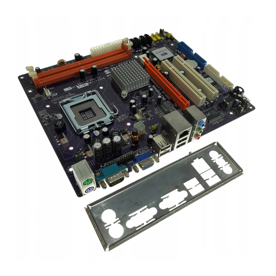
1. ставим перемычку
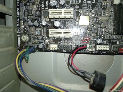
первое фото оригинал с моей мат платы, на фото я обвёл где находится перемычка
второе фото взято с сайта www.ecs.com (эта другая мат плата)
2. скачиваем и запускаем 120925K_CPUEVO.EXE (с оф сайта CPUEVO http://www.ecs.com.tw/extra/windows_8_support/intel_win8_biosupgrade.html ) у каждого модели она своя, выбираем под свою модель мат платы, не знаю нужен или нет — но компьютер был подключен к сети
3. после выкл компьютера убираем перемычку, обновилось благополучно, но не на последнюю версию.
4. запускаю из под винды прогу eBLU_1.3.5 (для всех мат плат) обновляется биос на пред последнюю версию
5. дальше обновлял через afuwin64 указав ту самую последнюю версию прошивки которую взял с оф сайта 06/19/2013 в формате CAP
ВСЁ это делается в 3 этапа обновления (три обновления биоса — все 5 пунктов), я обновлял мат плату так как она не хотела работать с видео картой GTX 750 TI (AFOX), можно было сделать всё в один этап (использую тока прогу 120925K_CPUEVO.EXE) но я решил обновить до последнее версией биоса (06/19/2013), а чтобы обновить до последней версии — я делал в не сколько этапов вплоть до пункта, с пункта 1 по 5, хотя после первого обновления биоса (пункт 2), мат плата благополучно заработала с видео картой GTX 750 TI
ps из под доса не прошилась даже с перемычкой, прошивка с форматом CAP скачена с оф сайта не прошилась даже с помощью afuwin из под винды, надо было выполнить 1 пункт (строго последовательно)
вообще прошивка мат плат ECS самая проблемная оказалась на моей практике, а все из-за внедрения и поддержки ME и перемычек…..нужна строгая последовательность
ТУТ официальный мануал по данной мам плате (ECS H61H2-M17 ver 1.0), по нему я нашёл где находится перемычка (сразу не разобрался без мануала где она находится, трудно найти)
откуда я качал CPUEVO http://www.ecs.com.tw/extra/windows_8_support/intel_win8_biosupgrade.html (это всё есть в архиве который я выкладывал выше в самом начале)
оф сайт где были взяты биосы http://www.ecs.com.tw/ECSWebSite/Product/Product_DOWNLOAD/EN/Motherboard/H61H2-M17%20-LL-V1-DO-0-RR-/Socket%201155-LL-Intel-RR- (ныне не раб ссылка)
https://www.ecsusa.com/ECSWebSite/Product/Product_DOWNLOAD/LP/Motherboard/H61H2-M17%20-LL-V1-DO-0-RR-/Socket%201155-LL-Intel-RR- более свежая ссылка раб на 2021 год
ссылки выше — откуда я качал последнюю версию биоса (это всё есть в архиве который я выкладывал выше в самом начале)
ссылки на ориг версии биоса — сделал зеркало на ссылки если оф сайт опять не будет работать, (то же взяты с оф сайта):
Архив (зеркало)
30619A10.CAP 06/19/2013 (самая свежая версия биоса)
1301031.CAP 01/03/2013 (более старый биос)
все биосы идут в формате *.CAP