Привет всем! Готов поделиться книгами mitsu colt совершенно бесплатно, чисто символически за подпись на мой Colt! Извиняйте, но ничего интересного у меня нет, так как машина куплена недавно!
В наличии:
Mitsubishi COLT с 2004 г.в. c бенз. дв. 4A90 и 4А91
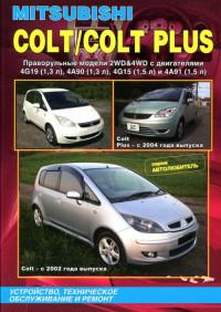
Mitsubishi COLT & COLT PLUS праворульные модели 2WD&4WD с двиг. 4G19, 4A90, 4G15 и 4A91
Ссылки на скачивание:
yadi.sk/i/I2F5bwj5uqSJW «правша»
yadi.sk/i/zQ1kFLOFuqSHY «евро»
Не забывайте подписываться на машину!
Удачи с кольтами!
Цена вопроса: 0 ₽
Войдите или зарегистрируйтесь, чтобы писать комментарии, задавать вопросы и участвовать в обсуждении.
Все комментарии
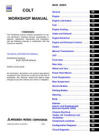
Руководство по эксплуатации автомобиля Mitsubishi Colt 5 (CJ)

Ключи от автомобиля и иммобилайзер
Запирание и отпирание К автомобилю прилагаются два ключа, подходящие ко всем замкам. Храните один из них в надежном месте в качестве запасного. Номер ключа выбит на его номерной пластинке. Запишите номер ключа и храните номерную…

Капот — открывание и закрывание
Открывание Для открывания капота потяните на себя рукоятку под панелью приборов. Нажмите на защелку и поднимите капот. Закрепите капот в поднятом положении, установив опорный стержень в его паз.

Система дополнительной безопасности SRS
Система дополнительной безопасности SRS состоит из следующих основных частей: 1. Подушка безопасности водителя, 2. Подушка безопасности пассажира, 3. Газогенераторы (включающие датчики удара), 4. Натяжители ремней безопасности….

Щиток приборов
На щитке приборов имеются следующие контрольно-измерительные приборы: 1. Указатель количества топлива, 2. Спидометр, 3. Указатель температуры воды, 4. Одометр, 5. Счетчик суточного пробега, 6. Кнопка сброса показаний суточного…

Индикаторные и сигнальные лампочки
1 — Сигнальная лампочка запаса топлива; 2 — Сигнальная лампочка открытия дверей; 3 — Индикаторная лампочка включения дальнего света фар; 4 — Индикаторные лампочки указателей поворотов/аварийной сигнализации; 5 — Лампочка…

Комбинированный переключатель
Фары Для включения освещения установите этот переключатель в следующие положения: Освещение выключено Включены габаритные огни, задние фонари, освещение номерного знака и освещение щитка приборов Включены фары Система напоминания…

Регулятор угла наклона фар
Угол наклона фар меняется в зависимости от величины груза, перевозимого автомобилем. Регулятором фар можно пользоваться для регулирования расстояния, освещаемого фарами (когда включен ближний свет), чтобы не ослеплять водителей…

Выключатель фароомывателей
Фароомыватели могут быть включены, когда ключ зажигания находится в положении «ON» и переключатель света фар находится в положениях или . Нажмите один раз на кнопку, и в течение приблизительно 0.5 секунды на фары будет подаваться…

Выключатель стеклоочистителей и стеклоомывателей
Этот выключатель работает, когда ключ зажигания находится в положении «ON» или «АСС». Включение стеклоочистителей или стклоомывателей производится соответствующим перемещением рычажного переключателя. Стеклоочистители У…

Выключатель противотуманных фар
Выключатель передних противотуманных фар Для включения передних противотуманных фар нажмите на выключатель один раз, а для выключения — нажмите на него еще раз. Выключатель задней противотуманной фары Тип 1 Задняя противотуманная…

Регулятор яркости освещения приборов
Регулятор действует, когда включены освещение или противотуманные фары (если таковые имеются). Регулировка производится вращением ручки. 1. Увеличение яркости; 2. Уменьшение яркости.

Замок зажигания
1. Двигатель выключен и рулевое колесо заблокировано. Ключ можно вставить и извлечь только в этом положении; 2. Двигатель выключен, могут работать радиоприемник, прикуриватель и т.п.; 3. Двигатель работает и включены все…

Механическая коробка передач
Схема переключения передач показана на рукоятке рычага переключения передач. Перед переключением рычага обязательно до конца выжимайте педаль сцепления.

Автоматическая трансмиссия
Автоматическая коробка передач с электронным управлением, предназначенная для оптимального управления автомобилем и способная к адаптивному регулированию, обеспечивает оптимальное переключение передач, соответствующее почти всем…

Антиблокировочная тормозная система
Антиблокировочная тормозная система предотвращает блокировку колес при торможении, сохраняя тем самым способность автомобиля двигаться в требуемом направлении, улучшает его управляемость и создает оптимальную силуторможеимя….

Система отопления и кондиционер
Система отопления и кондиционер работают только при заведенном двигателе. Работа системы отопления непосредственно связана с температурой охлаждающей жидкости в двигателе, поэтому управляйте ею, когда двигатель достаточно хорошо…

Запуск двигателя от внешнего источника тока
Если двигатель не запускается из-за разрядки аккумуляторной батареи, то для его запуска можно использовать батарею другого автомобиля, подключаемую через соединительные провода. 1. Установите автомобили достаточно близко один к…

Предохранители — расположение и номиналы
Для предотвращения выхода из строя электрической системы в результате короткого замыкания или перегрузки каждая отдельная электрическая цепь оснащена предохранителем. коробки с предохранителями расположены в салоне и в моторном…

Замена лампочек
Перед заменой лампочки удостоверьтесь, что она выключена. Не прикасайтесь к стеклу новой лампочки голыми руками. Кожный жир, оставшийся на стекле, после нагрева лампочки испарится, его пары осядут на рефлекторе и сделают его…

Перестановка колес
Для обеспечения равномерного и одинакового износа и увеличения срока службы всех шин производитель рекомендует производить перестановку колес приблизительно после каждых 10 000 км (6 250 миль) пробега автомобиля. Однако,…

Свободный ход рулевого колеса
Проверка свободного хода рулевого колеса производится путем его поворота в обе стороны. На автомобилях, оснащенных усилителем рулевого управления, при проверке свободного хода рулевого колеса двигатель должен быть включен и…

Свободный ход педали сцепления
Нажмите пальцами руки на педаль сцепления, пока не почувствуете первое сопротивление ее движению. Это расстояние должно находиться в определенных пределах. 1 — Свободный ход 6-13 мм (0.23-0.5 дюйма).

Свободный ход тормозной педали
Заглушите двигатель, и несколько раз выжмите до конца тормозную педаль. Затем нажмите на нее пальцами руки, пока не почувствуете первое сопротивление движению педали. Это расстояние должно находиться в определенных пределах. 1 -…

Ход рычага привода стояночной тормозной системы
Потяните на себя рычаг привода стояночной тормозной системы до упора для проверки количества щелчков, которые издаются его храповым механизмом. Один щелчок соответствует перемещению рычага на один зубец. Для нормального действия…
Ссылка в разных форматах на этот раздел
TEXTHTMLBB Code
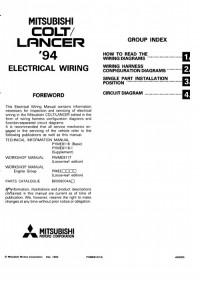
Сборник электросхем на английском языке автомобилей Mitsubishi Colt 1994-2001 и Mitsubishi Lancer 1994-2000 годов выпуска.
- Автор: —
- Издательство: Mitsubishi Motors Corp.
- Год издания: 1993-2000
- Страниц: —
- Формат: PDF
- Размер: 33,9 Mb
Сборник руководств на английском языке по техническому обслуживанию и ремонту автомобилей Mitsubishi Colt и Mitsubishi Lancer 1992-1996 годов выпуска.
- Автор: —
- Издательство: Mitsubishi Motors Corp.
- Год издания: —
- Страниц: —
- Формат: PDF
- Размер: 41,2 Mb
Руководство на английском языке по техническому обслуживанию и ремонту автомобилей Mitsubishi Colt и Mitsubishi Lancer 1993 года выпуска.
- Автор: —
- Издательство: Mitsubishi Motors Corp.
- Год издания: —
- Страниц: —
- Формат: PDF
- Размер: 99,9 Mb
Сборник руководств на английском языке по техническому обслуживанию и ремонту автомобилей Mitsubishi Colt и Mitsubishi Lancer 1996-2001 годов выпуска.
- Автор: —
- Издательство: Mitsubishi Motors Corp.
- Год издания: 1995-2000
- Страниц: —
- Формат: PDF
- Размер: 26,5 Mb
Сборник мультимедийных руководств на английском языке по техническому обслуживанию и ремонту автомобиля Mitsubishi Colt 2005-2011 годов выпуска.
- Автор: —
- Издательство: Mitsubishi Motors Corp.
- Год издания: —
- Страниц: —
- Формат: —
- Размер: 1,8 Gb
Сборник руководств на английском языке по техническому обслуживанию и ремонту автомобиля Mitsubishi Colt 2007 года выпуска.
- Автор: —
- Издательство: Mitsubishi Motors Corp.
- Год издания: 2006
- Страниц: —
- Формат: PDF
- Размер: 174,4 Mb
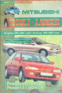
Руководство по ремонту автомобилей Mitsubishi Colt и Mitsubishi Lancer 1991-1995 годов выпуска с бензиновыми и дизельными двигателями.
- Автор: —
- Издательство: СверчокЪ
- Год издания: 2005
- Страниц: 279
- Формат: PDF
- Размер: 38,2 Mb
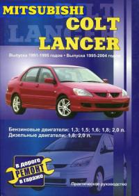
уководство по ремонту автомобилей Mitsubishi Colt и Mitsubishi Lancer 1991-2004 годов выпуска с бензиновыми и дизельными двигателями.
- Автор: В. Покрышкин
- Издательство: СверчокЪ
- Год издания: 2005
- Страниц: 279
- Формат: DjVu
- Размер: 19,9 Mb
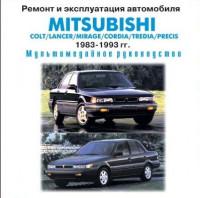
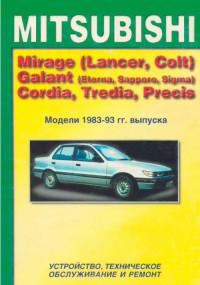
Мультимедийное руководство по эксплуатации и ремонту автомобилей Mitsubishi Colt/Lancer/Mirage/Cordia/Tredia/Precis 1983-1993 годов выпуска.
- Автор: —
- Издательство: —
- Год издания: —
- Страниц: —
- Формат: ISO
- Размер: 196,8 Mb
Сборник руководств по техническому обслуживанию и ремонту автомобилей Mitsubishi Colt и Mitsubishi Lancer 1996-2001 годов выпуска.
- Автор: —
- Издательство: Mitsubishi Motors Corp.
- Год издания: 1995-2000
- Страниц: —
- Формат: PDF
- Размер: 54,0 Mb
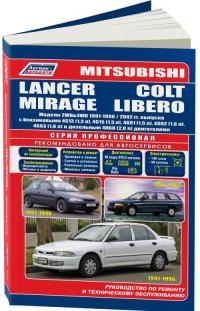
Руководство по эксплуатации, техническому обслуживанию и ремонту автомобилей Mitsubishi Colt/Lancer/Mirage 1991-1996 и Mitsubishi Libero 1992-2002 годов выпуска с бензиновыми и дизельными двигателями.
- Автор: —
- Издательство: Легион-Автодата
- Год издания: —
- Страниц: 448
- Формат: —
- Размер: —
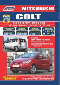
Руководство по эксплуатации, техническому обслуживанию и ремонту + каталог расходных запчастей автомобиля Mitsubishi Colt 2004-2012 годов выпуска с бензиновыми двигателями объемом 1,3/1,5 л.
- Автор: —
- Издательство: Легион-Автодата
- Год издания: —
- Страниц: 410
- Формат: —
- Размер: —
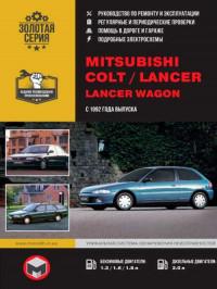
Руководство по эксплуатации и ремонту автомобилей Mitsubishi Colt и Mitsubishi Lancer/Lancer Wagon с 1992 года выпуска с бензиновыми и дизельными двигателями.
- Автор: —
- Издательство: Монолит
- Год издания: —
- Страниц: 326
- Формат: —
- Размер: —
Руководство по эксплуатации и ремонту автомобиля Mitsubishi Colt с 2002 года выпуска с бензиновыми и дизельными двигателями.
- Автор: —
- Издательство: Монолит
- Год издания: 2010
- Страниц: 292
- Формат: —
- Размер: —
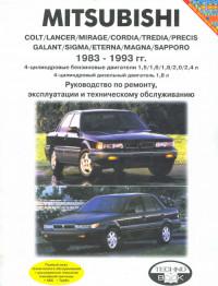
Руководство по эксплуатации, техническому обслуживанию и ремонту автомобилей Mitsubishi Colt/Lancer/Mirage/Cordia/Tredia/Precis/Galant/Sigma/Eterna/Magna/Sapporo 1983-1993 годов выпуска с бензиновыми и дизельными двигателями.
- Автор: —
- Издательство: Техно-BOOK
- Год издания: 2005
- Страниц: 273
- Формат: PDF
- Размер: 34,7 Mb

Руководство по эксплуатации, техническому обслуживанию и ремонту автомобилей Mitsubishi Colt и Mitsubishi Lancer 1993-2003 годов выпуска с бензиновыми и дизельными двигателями.
- Автор: —
- Издательство: Автомастер
- Год издания: 2003
- Страниц: 281
- Формат: PDF
- Размер: 16,4 Mb
Руководство по техническому обслуживанию и ремонту автомобилей Mitsubishi Mirage/Lancer/Colt/Galant/Eterna/Sapporo/Sigma/Cordia/Tredia/Precis 1983-1993 годов выпуска.
- Автор: —
- Издательство: MoToR
- Год издания: 1996
- Страниц: 183
- Формат: —
- Размер: —
Руководство по техническому обслуживанию и ремонту автомобилей Mitsubishi Colt и Mitsubishi Lancer 1984-1992 годов выпуска.
- Автор: Г.Р. Этцольд
- Издательство: Arinas
- Год издания: 1994
- Страниц: 339
- Формат: DjVu
- Размер: 10,4 Mb
Руководство по техническому обслуживанию и ремонту автомобилей Mitsubishi Colt с 2002 и Mitsubisi Colt Plus с 2004 года выпуска с бензиновыми двигателями объемом 1,3/1,5 л.
- Автор: —
- Издательство: Легион-Автодата
- Год издания: 2012
- Страниц: 376
- Формат: —
- Размер: —

Элементы приводного вала с роликовыми шарнирами 1 – ШРУС (B.J.); 2 – хомут; 3
Элементы приводного вала с шариковыми шарнирами 1 – вал корпус; 2, 3 – стопорное
Снятие Снимите фиксатор тормозного шланга разъем провода датчика частоты вращения колеса автомобили с ABS)
Поднимите переднюю часть автомобиля. Когда автомобиль поднят, можно легко проверить защитные чехлы шарниров приводных
Для привода передних ведущих колес в рассматриваемых моделях применяются приводы различных типов. Каждый привод
Обычно с приводными валами особых проблем не возникает. Срок их службы зависит, естественно, от
Валы коробки передач 1 _ картер сцепления; 2 – держатель подшипника; 3 – кольцо;
Снятие Сняв декоративную накладку, снимите фиксатор переходника. Слегка вытяните трос спидометра в салон автомобиля
Элементы механизма управления коробкой передач моделей поздних годов выпуска 1, 5 – соединение троса
Типичные элементы механизма переключения передач моделей ранних годов выпуска 1 – ручка рычага переключения
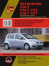
Mitsubishi Colt Mark VI (Z30, CZ3/CZT) с бензиновыми двигателями: 3A90/134910 1.1 л (1124 см³) 75 л.с./55 кВт, 4G19 1.3 л (1343 см³) 90 л.с./66 кВт, 4А90/135930 1.3 л (1332 см³) 92-95 л.с./68-70 кВт, 4G15/4G15T 1.5 л (1468 см³) 98-110-150-154-166 л.с./72-81-110-113-122 кВт, 4А91/135950 1.5 л (1499 см³) 105-106-109-111 л.с./77-78-80-81 кВт и дизельными OM639 1.5 л (1493 см³) 68-95 л.с./50-70 кВт; Руководство по эксплуатации, техническому обслуживанию и ремонту, регулярные и периодические проверки, помощь в дороге и гараже, уникальная система определения неисправностей, технические характеристики, цветные электросхемы, контрольные размеры кузова. Производственно-практическое издание компактный легковой автомобиль малого (субкомпактного) Б-класса Мицубиси Кольт с цельнометаллическими несущими кузовами трех- и пятидверный хэтчбек передне- и полноприводные модели шестого поколения выпуска (включая праворульные) с 2002 по 2008 год
ЕСЛИ ВЫ ВИДИТЕ ОШИБКУ 406 Not Acceptable и не видите документ, то скорей всего у Вас IP РФ и его надо сменить, на любой другой страны, с помощью VPN ( Scribd и SlideShare блокируют посетителей с Российским IP).
Видео Mitsubishi Colt mk6 замена тяги (солдатиков) стабилизатора и передних тормозных колодок (Мицубиси Кольт 02-08)
Mitsubishi Colt Mark VI общая информация (Мицубиси Кольт 2002-2008)
Проверка передних дисковых тормозов
Проверка и замена тормозных колодок
Примечание: при уменьшении толщины накладки тормозной колодки до 2 мм индикатор износа соприкасается с тормозным диском и во время движения издает визжащий звук для предупреждения водителя о необходимости срочной замены тормозных колодок.
1. Через специальное сервисное отверстие в тормозном суппорте измерьте толщину накладки тормозной колодки.
Номинальное значение …………. 10 мм
Предельно допустимое значение …………. 2 мм
Внимание;
— Если толщина накладки любой колодки меньше предельно допустимого значения, то замените тормозные колодки комплектом, кроме того, одновременно замените тормозные колодки на противоположном колесе данной оси.
— Если есть заметная разница в толщине накладок тормозных колодок с левой и с правой сторон суппорта, то проверьте плавность перемещения суппорта по направляющим пальцам.
2. Выверните нижний направляющий палец. Поднимите суппорт в сборе и подвесьте его на проволоке.
Внимание: не удаляйте специальную смазку с направляющего и стопорного пальцев и не допускайте попадания загрязнений на направляющий палец.
3. Снимите следующие детали со скобы суппорта:
— прокладки:
— тормозную колодку;
— тормозную колодку и индикатор износа в сборе;
— фиксаторы колодок.
Примечание: при установке деталей нанесите специальную консистентную смазку.
4. Измерьте сопротивление вращению ступицы колеса при снятых тормозных колодках.
5. Установите тормозные колодки и суппорт, затем измерьте сопротивление вращению ступицы колеса.
Проверка тормозного диска
Внимание: для обеспечения нормальной работы дисковых тормозов необходимо уделять особое внимание соблюдению технических требований при обслуживании дисковых тормозов.
Примечание: перед восстановительными операциями (перед механической обработкой) тормозного диска необходимо проверить указанные ниже параметры.
1. Отсутствие царапин, ржавчины, износа и пропитки поверхности диска продуктами износа накладок.
а) Если автомобиль некоторое время не эксплуатировался, то часть поверхности диска, не контактировавшая с накладками тормозных колодок, покроется ржавчиной, что приведет к повышенному шуму и вибрации.
б) Если перед установкой новых тормозных колодок не удалить канавки и царапины, появившиеся на поверхности диска в результате интенсивного износа, то нормальный контакт между диском и накладками тормозных колодок обеспечен не будет.
2. Отсутствие биения или выработки тормозного диска. Повышенное биение или выработка диска приведет к увеличению сопротивления нажатию на педаль тормоза из-за пульсации поршня колесного тормозного цилиндра.
3. Изменение толщины (непараллельность) тормозного диска. Если толщина тормозного диска не одинакова по периметру, то это приведет к вибрации педали тормоза.
4. Коробление (неплоскостность) тормозного диска.
Неправильное обслуживание либо перегрев приведет к короблению тормозного диска (неплоскостности).
Проверка толщины тормозных дисков
1. Используя микрометр, измерьте толщину тормозного диска в восьми точках приблизительно через каждые 45° на расстоянии 10 мм от наружного края диска.
Толщина тормозного диска:
Передние тормоза, модели с задними барабанными тормозами:
Номинальное значение …………. 20 мм
Предельно допустимое значение …………. 18,4 мм
Передние тормоза, модели с задними дисковыми тормозами:
Номинальное значение …………. 24,0 мм
Предельно допустимое значение …………. 22,4 мм
Задние тормоза:
Номинальное значение …………. 10,0 мм
Предельно допустимое значение …………. 8,4 мм
Примечание: разность толщины тормозного диска между любыми двумя точками измерений не должна превышать 0,015 мм.
2. Если толщина тормозного диска меньше предельно допустимого значения, то снимите его и установите новый. Если разность толщины тормозного диска между различными точками измерений превышает предельно допустимое значение, то необходимо либо заменить тормозной диски либо обработать его на специальной токарном станке.
| № | Спецификация / Specs | Данные |
| Габариты (мм/mm) и масса (кг/kg) / Dimensions and Weight | ||
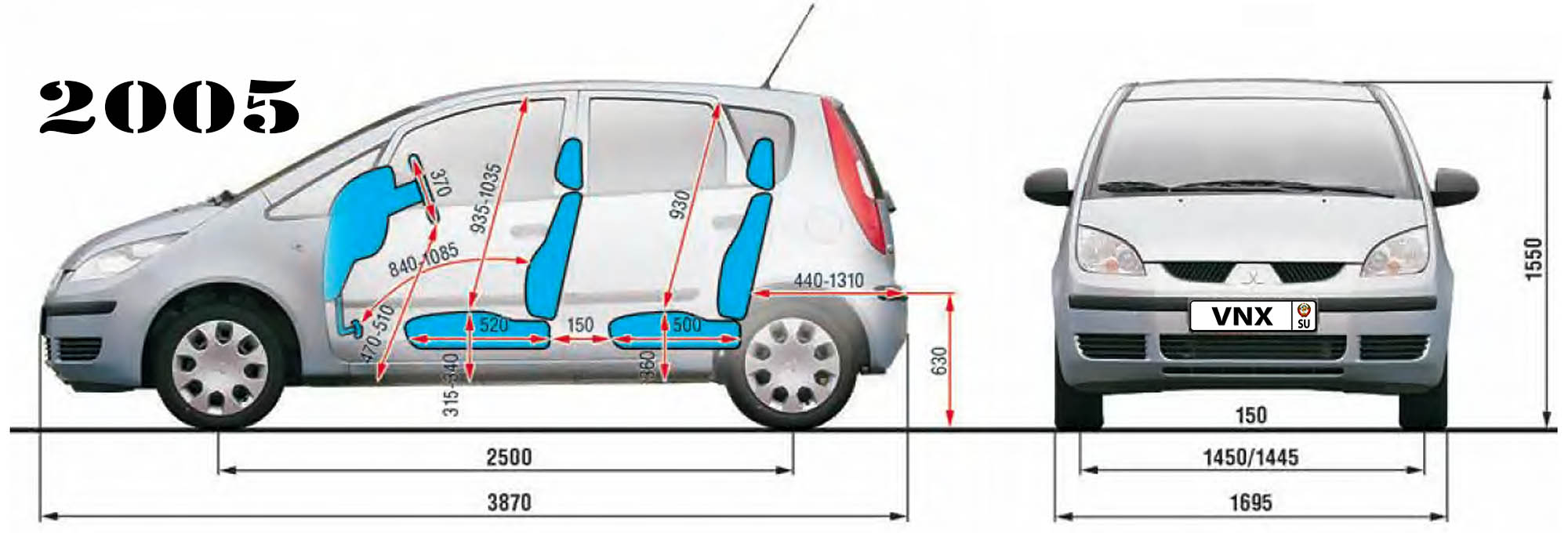
| 1 | Длина / Length | 3870 |
| 2 | Ширина (без/с зеркалами) / Width | 1695 |
| 3 | Высота (загружен/пустой) / Height | 1550 |
| 4 | Колёсная база / Wheelbase | 2500 |
| 5 | Дорожный просвет (клиренс) / Ground clearance | 150 |
| 6 | Снаряжённая масса / Total (curb) weight | 970 |
| Полная масса / Gross (max.) weight | 1450 | |
|
Двигатель / Engine |
||
| 7 | Тип / Engine Type, Code | Бензиновый, жидкостного охлаждения, четырехтактный, 3A90 |
| 8 | Количество цилиндров / Cylinder arrangement: Total number of cylinders, of valves | 3-цилиндровый, рядный, 12V, DOHC с верхним расположением двух распределительных валов |
| 9 | Диаметр цилиндра / Bore | 75.0 мм |
| 10 | Ход поршня / Stroke | 84.8 мм |
| 11 | Объём / Engine displacement | 1124 см³ |
| 12 | Система питания / Fuel supply, Aspiration | Распределенный впрыск топлива |
| Атмосферный | ||
| 13 | Степень сжатия / Compression ratio | 10.5:1 |
| 14 | Максимальная мощность / Max. output power kW (HP) at rpm | 55 кВт (75 л.с.) при 6000 об/мин |
| 15 | Максимальный крутящий момент / Max. torque N·m at rpm | 100 Нм при 3500 об/мин |
|
Трансмиссия / Transmission |
||
| 16 | Сцепление / Clutch type | 200×140 мм Однодисковое, сухое, с диафрагменной нажимной пружиной и гасителем крутильных колебаний, постоянно замкнутого типа |
| 17 | КПП / Transmission type | F5MGA МКПП 5 пятиступенчатая механическая, двухвальная, с синхронизаторами на всех передачах переднего хода |
О Книге
- Название: Mitsubishi Colt/ Colt CZ3/ Colt CZT Руководство по ремонту и эксплуатации
- Бензиновые двигатели: 3A90 1.1 л (1124 см³) 75 л.с./55 кВт, 4G19 1.3 л (1343 см³) 90 л.с./66 кВт, 4А90 1.3 л (1332 см³) 92-95 л.с./68-70 кВт, 4G15/4G15T 1.5 л (1468 см³) 98-110-150-154-166 л.с./72-81-110-113-122 кВт, 4А91 1.5 л (1499 см³) 105-106-109-111 л.с./77-78-80-81 кВт и дизельными OM639 1.5 л (1493 см³) 68-95 л.с./50-70 кВт
- Выпуск с 2002 года
- Серия: «Золотая»
- Год издания: 2010
- Автор: Коллектив авторов
- Издательство: «Ассоциация независимых издателей»
- Формат: PDF
- Страниц в книге: 292
- Размер: 50.99 МБ
- Язык: Русский
- Количество электросхем: 27
- Manuals
- Brands
- Mitsubishi Manuals
- Automobile
- COLT
- Owner’s manual
-
Contents
-
Table of Contents
-
Bookmarks
Quick Links
Chapters
-
Table of Contents
2 -
General Information
22 -
Locking and Unlocking
28 -
Seat and Seat Belts
40 -
Instruments and Controls
74 -
Starting and Driving
104 -
For Pleasant Driving
142 -
For Emergencies
186 -
Maintenance
214
Related Manuals for Mitsubishi Colt
Summary of Contents for Mitsubishi Colt
-
Page 1
OWNER’ S MANUAL… -
Page 2: Table Of Contents
Table of contents Overview General information Locking and unlocking Seat and seat belts Instruments and controls Starting and driving For pleasant driving For emergencies Vehicle care Maintenance Specifications…
-
Page 3
Overview Instruments and controls E00100104085 1. Steering wheel audio remote control switch* p. 5-28 2. Combination headlamps and dipper switch p. 3-20 Except for Clear Tec (LHD) Turn-signal lever p. 3-23 Headlamp levelling switch p. 3-22 3. Instruments p. 3-02 4. -
Page 4
Overview 1. Steering wheel audio remote control switch* p. 5-28 2. Combination headlamps and dipper switch p. 3-20 Clear Tec (LHD) Turn-signal lever p. 3-23 Headlamp levelling switch p. 3-22 3. Instruments p. 3-02 4. Windscreen wiper and washer switch p. 3-25 Rear window wiper and washer switch p. -
Page 5
Overview 1. Instruments p. 3-02 2. Windscreen wiper and washer switch p. 3-25 Except for Clear Tec (RHD) Rear window wiper and washer switch p. 3-29 3. Cruise control switch* p. 4-32 4. Front fog lamp switch* p. 3-24 5. Electric remote-controlled outside rear-view mirrors switch* p. -
Page 6
Overview 1. Instruments p. 3-02 2. Windscreen wiper and washer switch p. 3-25 Clear Tec (RHD) Rear window wiper and washer switch p. 3-29 3. Cruise control switch* p. 4-32 4. Electric remote-controlled outside rear-view mirrors switch* p. 4-09 5. Front fog lamp switch* p. 3-24 6. -
Page 7
Overview 1. Hazard warning flasher switch p. 3-23 2. Audio* p. 5-12 3. Supplemental restraint system (SRS) — airbag (for front passen- ger’s seat) p. 2-22 4. Heater* p. 5-04 Automatic air conditioning* p. 5-07 5. Front passenger’s airbag ON-OFF switch p. 2-25 6. -
Page 8
Overview 1. Audio* p. 5-12 2. Hazard warning flasher switch p. 3-23 3. Ventilators p. 5-02 4. Accessory socket p. 5-37 5. Fuel tank filler door release lever p. 02 6. Heated seats switch* p. 2-06 7. Cup holder (for front seats) p. 5-42 8. -
Page 9
Overview Interior E00100203005 1. Seat belts p. 2-10 LHD (3-door models) 2. Supplemental restraint system (SRS) — Curtain airbag* p. 2-30 3. Vanity mirror p. 5-37 4. Sun visors p. 5-36 5. Room lamp/Map lamps p. 5-38 6. Inside rear-view mirror p. 4-08 7. -
Page 10
Overview 1. Sun visors p. 5-36 2. Vanity mirror p. 5-37 RHD (3-door models) 3. Supplemental restraint system (SRS) — Curtain airbag* p. 2-30 4. Seat belts p. 2-10 5. Lock switch p. 1-12 6. Electric window control switch p. 1-11 7. -
Page 11
Overview 1. Electric window control switch p. 1-11 2. Lock switch p. 1-12 LHD (5-door models) 3. Seat belts p. 2-10 4. Supplemental restraint system (SRS) — Curtain airbag* p. 2-30 5. Vanity mirror p. 5-37 6. Sun visors p. 5-36 7. -
Page 12
Overview 1. Inside rear-view mirror p. 4-08 2. Room lamp/Map lamps p. 5-38 RHD (5-door models) 3. Sun visors p. 5-36 4. Vanity mirror p. 5-37 5. Supplemental restraint system (SRS) — Curtain airbag* p. 2-30 6. Seat belts p. 2-10 7. -
Page 13
Overview Luggage area (Except for vehicle with compact spare wheel) E00100401263 1. Luggage compartment lamp p. 5-38 3-door models 2. Tyre repair kit p. 6-07 3. Towing hook p. 6-06… -
Page 14
Overview 1. Tyre repair kit p. 6-07 5-door models 2. Luggage compartment lamp p. 5-38 3. Towing hook p. 6-06… -
Page 15
Overview Luggage area (Vehicle with compact spare wheel) E00100401276 1. Luggage compartment lamp p. 5-38 3-door models 2. Towing hook p. 6-06 3. Spare wheel p. 6-13 4. Jack p. 6-11 5. Wheel nut wrench p. 6-06… -
Page 16
Overview 1. Wheel nut wrench p. 6-06 5-door models 2. Towing hook p. 6-06 3. Luggage compartment lamp p. 5-38 4. Jack p. 6-11 5. Spare wheel p. 6-13… -
Page 17: Locking And Unlocking
Overview Exterior E00100503633 1. Electric window control p. 1-11 3-door models 2. Outside rear-view mirrors p. 4-08 3. Fuel tank filler p. 02 4. Locking and unlocking p. 1-05 Keyless entry system p. 1-03 5. Side turn-signal lamps p. 3-23, 8-24, 8-26 6.
-
Page 18
Overview 1. Antenna p. 5-33 3-door models 2. Stop and tail lamps p. 8-24, 8-27 3. Rear turn-signal lamps p. 3-23, 8-24, 8-27 4. Reversing lamp (LHD vehicles) p. 8-24, 8-29 Rear fog lamp (RHD vehicles) p. 3-24, 8-24, 8-29 5. -
Page 19
Overview 1. Electric window control p. 1-11 5-door models 2. Outside rear-view mirrors p. 4-08 3. Fuel tank filler p. 02 4. Locking and unlocking p. 1-05 Keyless entry system p. 1-03 5. Side turn-signal lamps p. 3-23, 8-24, 8-26 6. -
Page 20
Overview 1. High-mounted stop lamps p. 8-24, 8-30 5-door models 2. Antenna p. 5-33 3. Stop lamps p. 8-24, 8-27 4. Rear turn-signal lamps p. 3-23, 8-24, 8-27 5. Tail lamps p. 8-27 6. Reversing lamp (LHD vehicles) p. 8-24, 8-27 Rear fog lamp (RHD vehicles) p. -
Page 22
General information Fuel selection……………….02 Filling the fuel tank…………….02 Installation of accessories…………..04 Modification/alterations to the electrical or fuel systems….05 Genuine parts……………….05 Used engine oils safety instructions and disposal infor- mation………………05 Disposal information for used batteries………..06… -
Page 23: Fuel Selection
95 RON or higher have the system checked as soon as possible Gasoline is highly flammable and explo- at a MITSUBISHI MOTORS Authorized sive. You could be burned or seriously in- Service Point. jured when handling it. When refueling…
-
Page 24: Fuel Tank Filler Door Release Lever
General information WARNING CAUTION Keep the doors and windows closed while Since the fuel system may be under pres- refueling the vehicle. If they were open, sure, remove the fuel tank filler tube cap fuel vapour could get into the cabin. slowly.
-
Page 25: Installation Of Accessories
Due to large number of accessory and replacement parts of different manufactures available in the mar- ket, it is not possible, not only for MITSUBISHI MOTORS, but also for a MITSUBISHI MOTORS Authorized Service Point, to check whether the at- tachment or installation of such parts affects the overall safety of your MITSUBISHI-vehicle.
-
Page 26: Modification/Alterations To The Electrical Or Fuel Systems
Genuine parts Used engine oils safety electrical or fuel systems instructions and disposal E00200500574 MITSUBISHI MOTORS has gone to great lengths E00200400267 information to bring you a superbly crafted automobile offering MITSUBISHI MOTORS has always manufactured the highest quality and dependability.
-
Page 27: Disposal Information For Used Batteries
General information Disposal information for used batteries E00201300016 Your vehicle contains batteries and/or accumulators. Do not mix with general house- hold waste. For proper treatment, recovery and recycling of used batteries, please take them to applicable col- lection points, in accordance with your national legislation and the Directives 2006/66/EC.
-
Page 28
Locking and unlocking Keys………………..1-02 Electronic immobilizer (Anti-theft starting system)…..1-02 Keyless entry system…………..1-03 Doors………………..1-05 Central door locks……………..1-07 Dead Lock System*…………..1-07 “Child-protection” rear doors (5-door models)……1-09 Tailgate………………1-09 Manual window control (5-door models, rear door win- dow only)*…………….1-11 Electric window control…………..1-11… -
Page 29: Keys
Locking and unlocking Keys Electronic immobilizer (Anti- The key is a precision electronic device with a built-in signal transmitter. Please observe theft starting system) E00300101653 the following in order to prevent a malfunc- The key fits all locks. E00300201872 tion. The electronic immobilizer is designed to signifi- •…
-
Page 30: Keyless Entry System
If the engine istered in the immobilizer computer unit. does not start, we recommend you to con- The immobilizer can register up to 8 differ- tact your MITSUBISHI MOTORS Au- ent keys for use. thorized Service Point. CAUTION Do not modify or add parts to the immo- bilizer system.
-
Page 31
E00309500031 The remote control switch will operate with- 1. With the MITSUBISHI mark facing you, in- in approximately 30 seconds: relocking will in about 4 m from the vehicle. However, the sert a coin, etc., into the notch in the remote… -
Page 32: Doors
CAUTION You may purchase a replacement battery at an electric appliance store. Make sure the doors are closed: driving A MITSUBISHI MOTORS Authorized Serv- with doors incompletely closed is danger- ice Point can replace the battery for you if ous.
-
Page 33
Locking and unlocking To lock or unlock from inside the vehi- To lock without using the key NOTE The driver’s door cannot be locked using the Front passenger’s door inside lock knob while the driver’s door is opened. 1- Lock 2- Unlock Rear door (5-door models) Pull the inside door handle towards you to open… -
Page 34: Central Door Locks
Locking and unlocking Central door locks Dead Lock System* NOTE For RHD vehicles, turning the key in the E00300801445 E00305100013 The Dead Lock System helps to prevent theft. front door will not operate the central door When the keyless entry system has been used to locking system.
-
Page 35
When the UNLOCK switch (B) of the keyless en- the UNLOCK switch (B) has been pressed. try system is pressed to unlock the doors and tail- For details, please contact a MITSUBISHI gate, the Dead Lock System is simultaneously can- MOTORS Authorized Service Point. -
Page 36: Child-Protection» Rear Doors (5-Door Models)
Locking and unlocking “Child-protection” rear doors (5- Tailgate To lock or unlock from inside the vehi- door models) E00301400890 The tailgate can be locked or unlocked by using the E00300900638 inside lock knob (driver side), regardless of the po- WARNING sition of the ignition key.
-
Page 37
Locking and unlocking To open To close CAUTION Pull the tailgate lever upward to open the tailgate. Pull the tailgate grip (A) downward as illustrated and release it before the tailgate closes completely. Before driving, make sure that the tail- Gently slam the tailgate from the outside so that it gate is securely closed. -
Page 38: Manual Window Control (5-Door Models, Rear Door Win- Dow Only)
Locking and unlocking Manual window control (5-door Electric window control WARNING models, rear door window only)* E00302200042 The electric windows can only be operated with the Before operating the electric window con- E00302100083 ignition switch in the “ON” position. trol, make sure that nothing is capable of being trapped (head, hand, finger, etc.).
-
Page 39
Locking and unlocking Press the switch down for opening the window, To unlock, press it once again. and pull up the switch for closing. 1- Lock 1- Open (down) 2- Unlock 2- Close (up) WARNING NOTE The rear door windows (5-door models) only A child may tamper with the switch at open halfway. -
Page 40: Seat And Seat Belts
Seat and seat belts Seat………………..2-02 Seat arrangement…………….2-03 Seat adjustment…………….2-04 Front seat………………2-04 Head restraints…………….2-06 Making a luggage area…………..2-08 Seat belts………………2-10 Pregnant women restraint………….2-12 Seat belt pretensioner system and force limiter system….2-13 Child restraint…………….2-13 Seat belt inspection……………2-22 Supplemental restraint system (SRS) — airbag……2-22…
-
Page 41: Seat
Seat and seat belts Seat E00400101380 1-Front seat To adjust forward or backward ® p. 2-04 To recline the seatback ® p. 2-05 To adjust seat height* ® p. 2-05 To get in and out of the rear seat (3-door models) ® p. 2-05 Heated seats* ®…
-
Page 42: Seat Arrangement
Seat and seat belts Seat arrangement E00400200603 By operating the seats select the desired seats arrangement. Normal usage How to stow large articles (Folding the rear seat) 2-03…
-
Page 43: Seat Adjustment
Seat and seat belts Seat adjustment Front seat WARNING E00400300486 E00400400012 Adjust the driver’s seat so that you are comfortable To adjust forward or backward To minimize the risk of personal injury and that you can reach the pedals, steering wheel, E00400500505 in the event of a collision or sudden brak- Pull the seat adjusting lever and adjust the seat for-…
-
Page 44
Seat and seat belts To recline the seatback To adjust seat height* Fold the seatback forward, then slide the entire seat forward. E00400600623 E00400700578 In order to recline the seatback, lean forward slight- Adjust the seat height by repeatedly operating the To return the seat, slide the entire seat rearward ly, pull the seatback lock lever up, and then lean lever. -
Page 45: Head Restraints
Seat and seat belts Head restraints Heated seats* CAUTION E00401100625 E00403301181 The heated seats can be operated with the ignition • Children, elderly or ill people switch in the “ON” position. • People with sensitive skin WARNING • Excessively tired people •…
-
Page 46
Seat and seat belts To adjust height To remove Adjust the head restraint height so that the centre Lift the head restraint with the height adjusting of the restraint is as close as possible to eye level to knob (A) pushed in. reduce the chances of injury in the event of colli- sion. -
Page 47: Making A Luggage Area
Seat and seat belts Making a luggage area Folding the seatback forward (5-door Folding the rear seat models except for vehicles with turbo- E00403700335 E00403400244 To create luggage space, you can fold the rear seat. charger) WARNING E00414500014 NOTE Front seat Each side of the rear seat can be folded inde- If required, always operate the seating be- pendently of the other.
-
Page 48
Seat and seat belts 2. Lift up the center buckle and pull it through the seat cushion while pushing the rear of the seat cushion under the seatback. 3. Push down on the front of the seat cushion un- til it locks securely in place. Next, push and pull lightly on the seat to confirm that it has been securely retained. -
Page 49: Seat Belts
Seat and seat belts Seat belts NOTE WARNING You can check if the belt locks by pulling it E00404800607 To protect you and your passengers in the event of forward quickly. To reduce risk of serious or fatal injury an accident, it is the most important that the seat in an accident, including the deploying belts be worn correctly when you drive.
-
Page 50: Seat Belt Reminder/Warning Lamp
Seat and seat belts NOTE CAUTION WARNING For the front passenger seat, the warning func- tion works only while a person is sitting on In order to reduce the risk of serious or fa- The seat belts must not be twisted when the seat.
-
Page 51: Pregnant Women Restraint
Seat and seat belts Pregnant women restraint CAUTION WARNING E00405600136 Secure the seat belt using the seat belt hold- When adjusting the seat belt anchor, set it at a position that is sufficiently high so er. If the seat belt is not secured, it could WARNING be pinched between the seatback and the that the belt will make full contact with…
-
Page 52: Seat Belt Pretensioner System And Force Limiter System
MITSUBISHI To obtain the best results from your pre- er than in the front seat.
-
Page 53
Seat and seat belts Caution for installing the child re- WARNING straint on vehicle with front passenger Front passenger’s airbag ON A FORWARD FACING CHILD RE- airbag STRAINT should be used in the rear seat The label shown here is attached on vehicles with whenever possible;… -
Page 54
Seat and seat belts Instruction: WARNING CAUTION For small infants, an infant carrier should be used. For small children whose height when When the child restraint system is not in A child should never be left unattended seated allows the shoulder belt to lie in con- use, keep your child or infant seat se- in your vehicle. -
Page 55
IUF- Suitable for ISOFIX forward child restraints systems of universal category approved for use in the mass group. IL- Suitable for particular ISOFIX child restraint systems given in the following list (MITSUBISHI MOTORS genuine parts). X- ISOFIX position not suitable for ISOFIX child restraint systems in this mass group and/or this size class. -
Page 56
Seat and seat belts IL (Genuine part information) Genuine part No. ECE No. MZ313200 E1-04301133 NOTE MITSUBISHI MOTORS Europe B.V. reserves the right to changes without any prior announcement. For further information, please contact a MITSUBISHI MOTORS Authorized Service Point. 2-17… -
Page 57
Key of letters to be inserted in the table above: U- Suitable for “universal” category restraints approved for use in this mass group. L- Suitable for particular child restraints in the following list (MITSUBISHI MOTORS genuine parts). X- Seat position not suitable for children in this mass group. -
Page 58
The suitability table above applies to retention of child restraints using seat belts. When MITSUBISHI MOTORS genuine part No. MZ313200 is used on the rear seat, it can also be retained by means of ISOFIX child restraint mountings. There is no applicable MITSUBISHI MOTORS Genuine Parts to the Mass Group “0-Up to 10 kg (0-9 months)”. -
Page 59
Only a There are 2 child restraint anchorage points located the lower anchorage (ISOFIX child re- MITSUBISHI MOTORS genuine child restraint on the back of the rear seatbacks. These are for fas- straint mountings) and tether anchor- system can be used. -
Page 60
Seat and seat belts To install 3. Latch the tether strap hook (F) of the child WARNING seat to the tether anchorage bar (G) and tight- 1. Insert the child restraint system’s connectors en the top tether strap hook so it is securely (A) into the slit (B) in accordance with the in- When the vehicle is moving do not adjust fastened. -
Page 61: Seat Belt Inspection
MITSUBISHI MOTORS Authorized Service Point. Incorrect repair or replace- The SRS is NOT a substitute for the seat belts; for…
-
Page 62
Seat and seat belts WARNING WARNING IT IS VERY IMPORTANT TO AL- If the driver and front passenger are not WAYS PROPERLY WEAR YOUR properly seated and restrained, the air- SEAT BELT, EVEN WITH AN AIRBAG: bags may not protect you properly, and •… -
Page 63
Seat and seat belts WARNING WARNING Front passenger’s airbag OFF A REARWARD FACING CHILD RE- Older children should be seated in the STRAINT must NOT be used in the front rear seat, properly wearing the seat belt, passenger seat if the front passenger’s air- with an appropriate booster seat if needed. -
Page 64: Front Passenger’s Airbag On-Off Switch
Seat and seat belts How the Supplemental Restraint Sys- The front passenger’s airbag ON-OFF switch is lo- The airbags deployment produces a sudden, loud cated in the glove box. tem works noise, and releases some smoke and powder, but E00407301583 these conditions are not injurious, and do not indi- The SRS includes the following components: cate a fire in the vehicle.
-
Page 65
We recommend you to WARNING have the system inspected by a MITSUBISHI MOTORS Authorized To reduce risk of serious or fatal injury: Service Point. • Always remove the key from the igni- •… -
Page 66
Seat and seat belts The driver’s airbag and the front passenger’s air- bag are designed to inflate at the same time even if the passenger seat is not occupied. Deployment of front airbags E00407501367 The front airbags ARE DESIGNED TO DEPLOY when… -
Page 67
Seat and seat belts The front airbags are designed to deploy when the Examples of some typical conditions are shown in The front airbags ARE NOT DESIGNED TO DE- vehicle suffers a moderate to severe frontal impact. the illustration. PLOY when… A typical condition is shown in the illustration. -
Page 68
Seat and seat belts The front airbags MAY DEPLOY when… Because the front airbags may deploy in certain WARNING types of unexpected impacts as shown in the illus- The front airbags may deploy if the bottom of the tration that can easily move you out of position, it vehicle suffers a moderate-to-severe impact (under- Do not attach anything to the steering is important to always properly wear your seat… -
Page 69: Curtain Airbag System
The typical condition is shown in the illustration. inspected MITSUBISHI MOTORS Authorized Service Point. Side airbag system* E00407600084 The side airbags (A) are contained in the driver and Curtain airbag system* front passenger seatbacks.
-
Page 70
Seat and seat belts The side airbags and curtain airbags MAY NOT Because the side airbags and curtain airbags do not Oblique side impacts protect the occupant in all types of collisions, be DEPLOY when… sure to always properly wear your seat belts. With certain types of side collisions, the vehicle’s body structure is designed to absorb the shock to help protect the occupants from harm. -
Page 71
Seat and seat belts The side airbags and curtain airbags ARE NOT WARNING DESIGNED TO DEPLOY when… The side airbags and curtain airbags are not de- The side airbags and curtain airbags in- signed to deploy in conditions where they cannot flate with great force. -
Page 72
Failure to follow all of these instructions could lead to serious or fatal injury to the child. We recommend work around and on the side airbags and curtain airbags system to be done by a MITSUBISHI MOTORS Authorized Service Point. Improper… -
Page 73
If you junk or scrap the vehicle, we urge you Do not modify your steering wheel, seat to first take the vehicle to a MITSUBISHI belt retractor or any other SRS compo- MOTORS Authorized Service Point so that nents. -
Page 74: Instruments And Controls
Instruments and controls Instruments……………….3-02 Multi-information display………….3-04 Indication and warning lamps…………3-16 Indication lamps…………….3-17 Warning lamps…………….3-17 Combination headlamps and dipper switch……..3-20 Headlamp levelling switch…………3-22 Turn-signal lever…………….3-23 Hazard warning flasher switch………….3-23 Front fog lamp switch*…………..3-24 Rear fog lamp switch…………..3-24 Wiper and washer switch…………..3-25 Rear window demister switch…………3-29 Horn switch……………….3-30…
-
Page 75: Instruments
Instruments and controls Instruments E00500100762 1- Tachometer 3- Speedometer 2- Multi-information display 4- Multi-information meter switch 3-02…
-
Page 76
Instruments and controls Speedometer Tachometer E00500200819 E00500300735 The tachometer indicates the engine speed (r/min). Indication for km/h The tachometer can help you obtain more economi- The speedometer indicates the vehicle’s speed in cal driving and also warns you of excessive engine kilometers per hour (km/h). -
Page 77: Multi-Information Display
Instruments and controls Multi-information display E00519900362 Always stop the vehicle in a safe place before operating. The following information is included on the multi-information display: odometer, tripmeter, service reminder, fuel remaining, outside temperature, allshift lever position driving range, momentary and average fuel consumption and average speed. It is also possible to change elements such as the units used on the multi-information display.
-
Page 78
Instruments and controls Information display (when the ignition Odometer Service reminder switch is “OFF”) E00527800012 E00521300536 The odometer indicates the distance travelled. This displays the distance and number of E00528200026 months until the next periodic inspection. Each time you lightly press the multi-information Tripmeter Refer to “Service reminder”… -
Page 79
Instruments and controls Information display (when the ignition switch is “ON”) E00528300027 Each time you lightly press the multi-information meter switch in the meter or MODE/SET switch in the audio (if so equipped), the display switches in the follow- ing order. A- Lightly press the multi-information meter switch B- Lightly press the MODE/SET switch 3-06… -
Page 80
Instruments and controls 1- Odometer 6- Driving range display* 2- Tripmeter 7- Momentary fuel consumption display* 8- Average fuel consumption display* 3- Tripmeter 9- Average speed display* 4- Service reminder (distance) 5- Service reminder (month) NOTE Always stop the vehicle in a safe place before operating. Refer to “Changing the function settings (when the ignition switch is “ON”)”… -
Page 81
Instruments and controls Odometer NOTE NOTE E00527700011 The remaining distance is based “—” is displayed when the momen- The operation method is the same as on the previous fuel consumption tary fuel consumption cannot be when the ignition switch is “OFF”. data. -
Page 82
Instruments and controls When the ignition switch is switch- The memory of the auto reset When the ignition switch is switch- ed from “ACC” or “LOCK” to mode or manual reset mode for ed from “ACC” or “LOCK” to “ON”, the mode setting is automat- the average fuel consumption dis- “ON”, the mode setting is automat- ically switched from manual to au-… -
Page 83
Instruments and controls Outside temperature display Gearshift indicator* If fuel is added with the ignition switch in the “ON” position, the fuel gauge may incor- E00528400015 E00528600020 This displays the temperature outside the The gearshift indicator (if so equipped) rectly indicate the fuel level. vehicle. -
Page 84
2. Alerts the driver when the inspection time display. displayed time until the next periodic inspec- has arrived. We recommend you to consult a tion may differ from that of MITSUBISHI MITSUBISHI MOTORS Authorized Service MOTORS recommends. Point. In addition, the display settings for the next periodic inspection time can be modified. -
Page 85: Changing Function Settings
If you accidentally reset the display, we rec- ommend you to consult a MITSUBISHI MOTORS Authorized Service Point. Changing the function settings (when the ignition switch is “ON”)*…
-
Page 86
Instruments and controls (If there is no operation for about 10 seconds The icon will stop flashing if there is no oper- • When the ignition switch is switched with flashing, the display returns to the previ- ation for about 10 seconds or if the MODE/ from “ACC”… -
Page 87
Instruments and controls 1. When you lightly press the MODE/SET (If there is no operation for about 10 seconds The icon will stop flashing if there is no oper- switch a few times, the information display with flashing, the display returns to the previ- ation for about 10 seconds or if the MODE/ switches to the momentary fuel consumption ous display.) -
Page 88
Instruments and controls Changing the temperature unit 2. Press and hold the multi-information meter The icon will stop flashing if there is no oper- switch for about 2 seconds or more to dis- ation for about 10 seconds or if the multi-in- E00523100206 The display unit for temperature can be switched. -
Page 89: Indication And Warning Lamps
Instruments and controls Indication and warning lamps E00501501731 1- Turn-signal indication lamps/Hazard warning indication lamps ® p. 3-17 12- Traction control system (TCL)/Active stability control system (ASC) indi- 2. Front fog lamp indication lamp* ® p. 3-17 cation lamp* ® p. 4-31 3- High-beam indication lamp ®…
-
Page 90: Indication Lamps
Instruments and controls Indication lamps Warning lamps High-beam indication lamp E00501800072 E00501600012 E00502400017 This indication lamp illuminates when Turn-signal indication lamps/ Brake warning lamp the high-beam is used. Hazard warning indication E00502502445 This lamp illuminates when the ignition lamps Front fog lamp indication switch is turned to the “ON”…
-
Page 91
Instruments and controls CAUTION CAUTION CAUTION Furthermore, vehicle • Should the brakes fail, use Prolonged driving with this should be brought immediately engine braking to reduce lamp on may cause further dam- to a stop in a safe location and your speed and pull the park- age to the emission control sys- we recommend you to have it… -
Page 92
Instruments and controls Charge warning lamp CAUTION CAUTION E00502700036 This lamp illuminates when the ignition If this lamp illuminates when If the lamp illuminates during switch is turned to the “ON” position, the engine oil level is not low, vehicle operation, it indicates and the lamp goes off after the engine have it inspected. -
Page 93: Combination Headlamps And Dipper Switch
Instruments and controls Combination headlamps and Type 1 CAUTION Rotate the switch to turn on the lamps. dipper switch Before moving your vehicle, E00506000923 check that the warning lamp is OFF. Headlamps NOTE Do not leave the headlamps and other lamps on for a long time while the engine is station- ary (not running).
-
Page 94: Headlamp Flasher
Instruments and controls Dipper (High/Low beam change) All lamps off E00506200505 When the lamp switch is in the “ ” position, the With the ignition switch in the beam changes from high to low (or low to high) “ON” position, headlamps, posi- each time the lever is pulled to (1).
-
Page 95: Headlamp Levelling Switch
(for vehicles equipped with the automatic For details, we recommend you to consult a lamps’ glare does not distract the drivers of ap- lamp control). MITSUBISHI MOTORS Authorized Service proaching vehicles. 2. Turn the ignition switch to the “OFF” posi- Point.
-
Page 96: Turn-Signal Lever
Instruments and controls Turn-signal lever Hazard warning flasher switch Switch position 0- Driver only/Driver + 1 front passenger E00506501000 E00506600727 The turn-signal lamps flash when the lever is oper- Use the hazard warning flasher switch when the ve- Switch position 2- 5 passengers (including driver) ated (with the ignition switch in the “ON”…
-
Page 97: Front Fog Lamp Switch
Instruments and controls Front fog lamp switch* Rear fog lamp switch NOTE While the hazard warning lamps are blinking E00506800820 E00506900296 The front fog lamps illuminate only when the head- The rear fog lamps illuminate only when the head- due to having manually pushed the switch, lamps or tail lamps turn on.
-
Page 98: Wiper And Washer Switch
Instruments and controls Wiper and washer switch NOTE If the blades are frozen to the windscreen, do not operate the wipers until the ice has melted and the The rear fog lamp is automatically turned off E00507101191 blades are freed, otherwise the wiper motor may be when the headlamps and front fog lamps (if damaged.
-
Page 99
For further information, please contact your The windscreen wipers can be operated with the ig- The wipers will automatically authorized MITSUBISHI MOTORS dealer. nition switch in the “ON” or “ACC” position. operate depending on the degree of wetness on the windscreen. -
Page 100
Instruments and controls please contact your authorized MITSUBISHI Keep the lever in the “ ” (OFF) position if the CAUTION MOTORS dealer. windscreen is dirty and the weather is dry. • When the wipers operate at a constant in- Wiper operation under these conditions can scratch With the ignition switch in the “ON”… -
Page 101
For details, we recommend you to consult a MITSUBISHI MOTORS Author- The wipers will operate once if the lever is moved ized Service Point. -
Page 102: Rear Window Demister Switch
Instruments and controls Rear window demister switch Rear window wiper and washer ommend you to consult a MITSUBISHI MOTORS Authorized Service Point. E00507300532 E00507900990 • It is possible to disable the function that The rear window demister switch can be operated…
-
Page 103: Horn Switch
Instruments and controls Horn switch CAUTION E00508000581 Pressing the “ ” mark on the steering wheel, cau- To avoid unnecessary discharge of the bat- ses the horn to sound. tery, do not use the rear window demister during starting of the engine or when the engine is not running.
-
Page 104: Starting And Driving
Starting and driving Economical driving……………4-02 Driving, alcohol and drugs…………4-02 Safe driving techniques…………..4-03 Running-in recommendations…………4-04 Parking brake…………….4-06 Parking………………4-07 Steering wheel height adjustment……….4-07 Inside rear-view mirror…………..4-08 Outside rear-view mirrors………….4-08 Ignition switch…………….4-10 Steering wheel lock…………..4-11 Starting………………4-11 Auto Stop & Go (AS&G) system*……….4-13 Manual transmission…………..4-16 Automated manual transmission……….4-19 How to drive a vehicle with an automated manual trans- mission………………4-22…
-
Page 105: Economical Driving
Starting and driving Economical driving Driving, alcohol and drugs Speed The higher the vehicle speed, the more fuel con- E00600100763 E00600200012 For economical driving, there are some technical re- Driving after drinking alcohol is one of the most fre- sumed. Avoid driving at full speed. Even a slight re- quirements that have to be met.
-
Page 106: Safe Driving Techniques
Starting and driving Safe driving techniques Carrying children in the vehicle Never leave your vehicle unattended with the E00600300390 Driving safety and protection against injury cannot key and children inside the vehicle. Children be fully ensured. However, we recommend that may play with the driving controls and this you pay extra attention to the following: could lead to an accident.
-
Page 107: Running-In Recommendations
Starting and driving Running-in recommendations E00600402177 During the running-in period for the first 1,000 km (620 miles), it is advisable to drive your new vehicle using the following precautions as a guideline to aid long life as well as future economy and performance. Do not race the engine at high speeds.
-
Page 108
Starting and driving NOTE The engine model is indicated on the vehicle information code plate. Refer to “Vehicle information code plate” on page 9-02. Vehicles with automated manual transmission Shift point Speed limit 30 km/h (19 mph) gear 50 km/h (30 mph) gear gear 80 km/h (50 mph) -
Page 109: Parking Brake
Starting and driving Parking brake NOTE CAUTION Apply sufficient force to the parking brake E00600501588 To park the vehicle, first bring it to a complete lever to hold the vehicle stationary after the If the brake warning lamp does not extin- stop, fully apply the parking brake lever sufficient- foot brake is released.
-
Page 110: Parking
Starting and driving Parking Steering wheel height adjustment Parking with the engine running Never leave the engine running while you take a E00600601521 E00600700466 To adjust the steering wheel height, release the tilt short sleep/rest. Also, never leave the engine run- Parking on a hill lock lever while holding the steering wheel by ning in a closed or poorly ventilated place.
-
Page 111: Inside Rear-View Mirror
Starting and driving Inside rear-view mirror Outside rear-view mirrors WARNING E00600800047 E00600900442 The lever (A) at the bottom of the mirror can be The sense of distance that you get from Compound curved-surface mirror used to adjust the mirror to reduce the glare from an object you see on the inner side of the the headlamps of vehicles behind you during night (LHD vehicles only)
-
Page 112: Heated Mirror
Starting and driving Manual remote-controlled outside rear-view mir- To fold the mirror rors* E00601100454 The outside mirror can be folded in towards the Adjust the mirror position by operating the lever as side window to prevent damage when parking in indicated by the arrows.
-
Page 113: Ignition Switch
Starting and driving Ignition switch The indication lamp (A) will illuminate while the NOTE demister is on. The heater will be turned off auto- For vehicles equipped with the Daytime Run- E00601401500 matically in about 20 minutes. ning Lamp, when the ignition switch is in the “ON”, the headlamp low beams etc.
-
Page 114: Steering Wheel Lock
Starting and driving Steering wheel lock Starting CAUTION E00601500605 E00601601007 If the engine is stopped while driving, the Tips for starting brake servomechanism will cease to func- Do not operate the starter motor continuous- tion and braking efficiency will deterio- ly longer than 10 seconds;…
-
Page 115
Starting and driving 5. Place the gearshift lever in the “N” (Neutral) 4. Turn the ignition key to the “ON” position CAUTION position. and make certain that all warning lamps are functioning properly. Do not run the engine at high rpm or 5. -
Page 116: Auto Stop & Go (As&G) System
Starting and driving Auto Stop & Go (AS&G) system* If you turn the ignition key to the “START” While depressing the brake pedal, fully de- position when the gearshift is not in the “N” press the clutch pedal and place the gearshift E00627400022 (Neutral) position, the multi-information dis- lever in the “N”…
-
Page 117
Starting and driving NOTE • Bonnet is open CAUTION • After the engine restarts automatically, Under normal conditions, the “ ” indication the vehicle speed has not exceeded ap- lamp will also illuminate for a few seconds • Do not leave the driver’s seat or open proximately 5 km/h (3 mph) when the ignition switch is turned to the the bonnet. -
Page 118
Starting and driving If the Auto Stop & Go (AS&G) system oper- Automatically restarting the engine CAUTION ates while the air conditioner is operating, E00627600066 Depress the clutch pedal while the gearshift lever is both the engine and the air conditioning com- system. -
Page 119: Manual Transmission
“Auto Stop & Go (AS&G) OFF” operate. switch. We recommend you to consult a MITSUBISHI When the Auto Stop & Go (AS&G) system is deac- MOTORS Authorized Service Point. tivated, the “ ” indication lamp will be illumina- ted in the meter.
-
Page 120
Starting and driving To avoid grinding noises when shifting into reverse, wait approximately 3 seconds with the clutch depressed when the vehicle is sta- tionary. Changing gears E00610600240 Always take care to change the gear with the vehi- cle speed matched to the engine speed. Proper shift- ing will improve fuel economy and prolong engine life. -
Page 121
Starting and driving Possible driving speed E00610801311 Speed limit Shift point 1100 models 1300 models Engine model 134910 Engine model 3A91 Engine model 135930 Engine model 4A90 45 km/h (28 mph) 45 km/h (28 mph) 45 km/h (28 mph) 50 km/h (30 mph) gear 80 km/h (50 mph) 85 km/h (53 mph) -
Page 122: Automated Manual Transmission
Starting and driving Automated manual transmission The currently selected shift position, manual mode or automatic mode is indicated on the multi-infor- E00612500038 mation display (B). An automated manual transmission is a transmis- sion in which operation of the clutch and shifting of gears are performed automatically under electron- ic control.
-
Page 123
Starting and driving Allshift lever position and multi-information display E00612600055 Multi-information display Allshift lever position Description N (Neutral) Power is not transmitted. This is the only position where the engine can be started. R (Reverse) This position is used for reversing. Gearshifts are performed automatically at all vehicle speeds (from a standing start automatic mode* right up to highway speeds). -
Page 124
Starting and driving Moving the allshift lever NOTE Whenever the allshift lever is placed in the “A” (Au- to) position from the “S” (Stand by) position, the E00612700014 You must have the brake pedal firmly de- The allshift lever is operated as follows; transmission switches from the automatic mode to pressed when moving the allshift lever. -
Page 125: How To Drive A Vehicle With An Automated Manual Transmission
Starting and driving How to drive a vehicle with an Performing gearshifts (manual mode) CAUTION E00612900061 automated manual transmission 1. Choose the manual mode using the allshift To maintain good running performance, lever. Refer to “Choosing between automatic E00613000014 the transmission may refuse to perform Starting from a standstill mode and manual mode”…
-
Page 126
Starting and driving NOTE NOTE CAUTION If the brake pedal is not depressed when the When “ ” and the allshift lever position dis- allshift lever is moved, a gearshift will not play are flashing alternately, an upshift is rec- When pulling away from a standstill on take place. -
Page 127
Starting and driving 2. While depressing the brake pedal, securely WARNING CAUTION apply the parking brake. 3. Move the allshift lever into the “S” (Stand Hard engine braking can cause the tyres Continue to pay attention to the vehicle by) position when parking on an uphill to slip on the road surface, possibly lead- while stationary. -
Page 128: Braking
Starting and driving Braking CAUTION WARNING E00607001801 All the parts of the brake system are critical to safe- If the power assist is lost or if either When leaving the vehicle, be sure to stop ty. We recommend you to have the vehicle the engine and remove the key from the brake hydraulic system stops working checked at regular intervals according to the serv-…
-
Page 129: Emergency Stop Signal System
Starting and driving Emergency stop signal system It deactivates when one of the following con- WARNING ditions is met. E00626000021 • The brake pedal is released. This is a device that reduces the possibility of rear Do not leave any objects near the brake •…
-
Page 130: Brake Assist System
Starting and driving Brake assist system Anti-lock brake system (ABS) When the brake assist system is in use, you may feel as if the depressed brake pedal is E00627000262 E00607100791 soft, the pedal moves in small motions in con- The brake assist system is a device assisting drivers Environmental conditions can have an effect on junction with the sound of the ABS opera- who cannot depress the brake pedal firmly when it…
-
Page 131
Never install a limited-slip differential, If the warning lamp stays on or does not wheel lock when you are driving over man- which is not MITSUBISHI MOTORS gen- illuminate when you start the vehicle, it in- holes, steel road-work plates, or the vehicle… -
Page 132: Electric Power Steering System
Do not stop the engine while driving. to consult a MITSUBISHI MOTORS Author- With the engine stopped, the steering ac- ized Service Point. tion would become extremely heavy and an unexpected accident might occur.
-
Page 133: Traction Control System (Tcl)/Active Stability Control System (Asc)
(ASC) will not work properly. again when the vehicle is driven, we recom- mend you to have the power steering inspec- ted by a MITSUBISHI MOTORS Author- ized Service Point. 4-30…
-
Page 134
MITSUBISHI Active stability control system (ASC) MOTORS Authorized Service Point. If the vehicle is towed with the ignition… -
Page 135: Cruise Control
Starting and driving Cruise control* Cruise control switches on the cruise control. The “CRUISE” indica- tion lamp in the meter cluster will come on. E00609100623 Cruise control is an automatic speed control system that keeps a set speed. It can be activated at about 40 km/h (25 mph) or more.
-
Page 136
Starting and driving 2. Accelerate or decelerate to your desired When you reach your desired speed, release the Accelerator pedal speed, then press and release the “COAST switch. Your new cruising speed is now set. While driving at the set speed, use the accelerator SET”… -
Page 137
Starting and driving When you reach your desired speed, release the Brake pedal To temporarily increase or decrease switch. Your new cruising speed is now set. While driving at the set speed, use the brake pedal, the speed which disengages the cruise control, then press the E00609600149 “COAST SET”… -
Page 138
Press the “ON OFF” switch to turn off (25 mph) or less. the cruise control and have your vehicle When the Active Stability Control system inspected by a MITSUBISHI MOTORS (ASC) starts operating. (if so equipped) Authorized Service Point. Refer to “Traction control system (TCL)/Ac- tive stability control system (ASC)”… -
Page 139: Cargo Loads
MITSUBISHI MOTORS Authorized Service Point. CAUTION The regulations concerning the towing of a trailer may differ from country to country. You are ad- When loading luggage, be careful to the vised to obey the regulations in each area.
-
Page 140
Starting and driving Towing bar mounting specifications 3-door models 464 mm (unladen) 111 mm See the following table for fixing points (A) for the 389 mm (laden) towing bar. 456 mm 435 mm 445 mm 470 mm 150 mm 504 mm 13 mm 118 mm 137 mm… -
Page 141
Starting and driving 5-door models The body, brakes, clutch, and chassis will be 473 mm (unladen) 222.5 mm under additional strain when towing a trailer. 395 mm (laden) The heavier weight and higher rolling and air 456 mm 183 mm resistance will increase fuel consumption. -
Page 142: For Pleasant Driving
For pleasant driving Ventilators………………5-02 Heater*………………5-04 Automatic air conditioning*…………5-07 Important operation tips for the air conditioning……5-11 Air purifier………………5-12 LW/MW/FM electronic tuning radio with CD player*….5-12 To use the external audio input function……..5-27 Steering wheel audio remote control switches*……5-28 Error codes………………5-30 Handling of compact discs…………5-32 Antenna………………5-33 Digital clock*…………….5-34 Sun visors………………5-36…
-
Page 143: Ventilators
For pleasant driving Ventilators Close the ventilators by pushing the section of the Changing the mode selection (B). E00700301398 E00700100647 To change the position and amount of air flowing from the ventilators, turn the mode selection dial. Open Close (Refer to “Mode selection dial” on pages 5-05, 5-08.
-
Page 144
For pleasant driving Foot/Face position Foot position Foot/Demister position Air flows to the upper part of the passenger com- Air flows mainly to the leg area. Air flows to the leg area, the windscreen and the partment, and flows to the leg area. door windows. -
Page 145: Heater
For pleasant driving Heater* Demister position Demister/Face position Air flows mainly to the windscreen and the door Air flows to the windscreen, the door windows and E00700500090 windows. the upper part of the passenger compartment. The heater can only be used while the engine is run- ning.
-
Page 146
For pleasant driving When the blower speed selection dial is set to the NOTE Recirculated air {Indication lamp (A) is ON} “0” position, all fan-driven airflow will stop. Air is recirculated inside the passenger com- While the engine coolant temperature is low, partment. -
Page 147
For pleasant driving Operating the heater system The air flow will be directed to the leg area and the For ordinary demisting upper part of the passenger compartment. Select de- Use this setting to keep the windscreen and door E00701800393 sired blower speed. -
Page 148: Automatic Air Conditioning
For pleasant driving Automatic air conditioning* For quick demisting Introduction of outside air E00702200352 E00702400022 To introduce air into the vehicle during hot weath- The air conditioning can only be used while the en- er, set the air selection switch (A) to the outside po- gine is running.
-
Page 149
For pleasant driving Never place anything on top of the sensor, Temperature control dial Mode selection dial since doing so will prevent it from function- E00703000490 E00703200447 The temperature control dial is used to adjust the To change the amount of air flowing from the ven- ing properly. -
Page 150
(A) will come on. tion is included to improve the efficiency of MITSUBISHI MOTORS Authorized Service Point. If the air conditioning indication lamp the air conditioning. If the outside air temper- ature rises, the air conditioning automatically no longer flashes, there is no problem. -
Page 151
For pleasant driving Turn the temperature control dial clockwise or anti- 2. Set the air selection switch (A) to the outside Warm air flows to the leg area and unheated or clockwise to the desired temperature. Select the de- position. slightly warm air (depending upon temperature set- sired blower speed. -
Page 152: Important Operation Tips For The Air Conditioning
For pleasant driving Important operation tips for the 3. Select your desired blower speed by turning Do not set the temperature control dial to the the blower speed selection dial. max. cool position. Cool air will blow air conditioning 4. Select your desired temperature by turning against the window glasses and form mist on E00708300948 the temperature control dial.
-
Page 153: Air Purifier
For pleasant driving Air purifier LW/MW/FM electronic tuning It is recommended that the refrigerant be recovered and recycled for further use. radio with CD player* E00708400024 An air filter has been incorporated into this air con- E00708502175 During a long period of disuse ditioning so that dirt and dust are cleaned from the The audio system can be used when the ignition air.
-
Page 154
For pleasant driving Volume and tone control panel SCV (Speed Compensated Volume) SCV function is a feature that automatically adjusts E00708600882 the VOLUME, BASS, and TREBLE settings in ac- cordance with the vehicle speed. Press the audio ad- just button (6) either to select OFF or the desired settings 1-6. -
Page 155
For pleasant driving 3. In future, when you gently press the memory select button in the audio adjust mode, the au- dio adjustment condition memorised for that button will take effect. 5-14… -
Page 156
For pleasant driving Radio control panel and display E00708900931 1- PWR (On-Off) switch 6- ST (Stereo) indicator 2- Memory select buttons 7- FM (FM1/FM2/FM3) indicators 3- FM/AM (FM/MW/LW selection) button 8- Preset memory number display 4- TUNE/SEEK (Down-step/Down-seek) button 9- Frequency display window 5- TUNE/SEEK (Up-step/Up-seek) button 5-15… -
Page 157
For pleasant driving To listen to the radio To enter frequencies into the memory NOTE E00716100974 E00709000711 Disconnecting the battery terminal erases all 1. Press the PWR switch (1) to turn the audio the radio frequencies stored in the memory. Manual setting system on and off. -
Page 158
For pleasant driving Radio data system (RDS) E00709200348 1- PWR (On-Off) switch 8- Menu button 2- Memory select buttons 9- RDS (Radio data system) indicator 3- TUNE/SEEK (Down-step/Down-seek) button 10- AF (Alternative frequencies) indicator 4- TUNE/SEEK (Up-step/Up-seek) button 11- TP (Traffic program identification) indicator 5- FM/AM (FM/MW/LW selection) button 12- PTY (Program type)/CT (Clock time) indicator 6- TP (Traffic program) button… -
Page 159
For pleasant driving AF (Alternative Frequencies) function If there are no frequencies broadcasting the same 18. CHILDREN programming, the radio searches a frequency broad- 19. SOCIAL E00720900146 The AF function finds a station broadcasting the casting the regional programming. The radio suc- 20. -
Page 160
For pleasant driving 4. When the radio picks up a station with your 3. The preset memory setting is retrieved by desired PTY, the display will show the name pressing the button and then releasing it with- of the station. in about 2 seconds. -
Page 161
For pleasant driving 2. If the radio detects traffic information on ei- Emergency broadcasts ther the station currently selected or another E00721700183 station, the display will show “TRAF INF” for 5 seconds followed by a 2-second indica- tion of the frequency. Then, it will show the name of the station broadcasting the traffic in- formation to which you will listen. -
Page 162
For pleasant driving MUTE 1. Press the “MENU” button to select the func- tion setup mode. Language of PTY display NOTE 2. Press the “MENU” button repeatedly to se- 3. Select the desired setting for each mode to be lect the mode you wish to change. The order Although “PHONE IN (PH)”… -
Page 163
For pleasant driving The setting will be shown on the display. Example NOTE After selecting a mode, you can leave the func- tion setup mode by taking either of the fol- lowing steps: • Press the “MENU” button for at least 2 seconds. -
Page 164
For pleasant driving CD control panel and display (MP3 compatible type) E00709500950 music CDs MP3 CDs 1- PWR (On-Off) switch 11- TRACK (Track down/up) button 2- CD eject button 12- CD indicator 3- Disc-loading slot 13- TRACK indicator 4- FOLDER (Folder down) button 14- DISC TEXT indicator 5- FOLDER (Folder up) button 15- NAME indicator… -
Page 165
For pleasant driving To listen to a CD NOTE 2. Press the CD button (9) for 2 seconds or lon- ger to switch to MP3 CD mode from normal E00709601554 When you have fast-forwarded/fast-reversed 1. Insert disc with label facing up. music CD mode. -
Page 166
For pleasant driving For information on CD-Rs/RWs, refer to Track up Folder selection “Notes on CD-Rs/RWs” on page 5-33. Press the side of the TRACK button (11) repeat- edly until the desired track number appears on the In the order display. -
Page 167
For pleasant driving NOTE Press the RPT/RDM button (10) three times. CD text “D-RDM” will appear on the display. Tracks from The CD player can display disc and track titles for The repeat mode will be cancelled by press- all the folders on the currently selected disc will be discs encoded with disc and track title information. -
Page 168: To Use The External Audio Input Function
For pleasant driving To use the external audio input MP3 title NOTE The CD player can display folder and track titles To return from ID3 tag information to the function for discs encoded with folder and track informa- folder name, press the TEXT button (6) E00732200771 tion.
-
Page 169: Steering Wheel Audio Remote Control Switches
For pleasant driving Steering wheel audio remote 2. Press the AUX button (2). Compared to the CD player mode and radio The display (3) will show “AUX” and then mode, the vehicle’s speaker volume will be control switches* the external audio input mode will be activa- lower in the external audio input mode.
-
Page 170: Volume Adjustment
For pleasant driving Volume adjustment Fast-reverse You can fast-reverse the disc by holding down the Volume up button — 1 fast-reverse button (5). While the button is kept While the button is pressed, the volume continues pressed, the disc will be fast-reversed. to increase.
-
Page 171: Error Codes
For pleasant driving Error codes E00710100972 If an error code (1) appears in the display, take action in accordance with the table below. 5-30…
-
Page 172
Inside of audio system is hot. Internal protection against high temperatures. nutes. Communication error between external device Communication or power supply Consult a MITSUBISHI MOTORS Author- and audio equipment. error ized Service Point. Power supply error of external device. MP3 CD mode was selected even though inser-… -
Page 173: Handling Of Compact Discs
For pleasant driving Handling of compact discs The use of special shaped, damaged compact • When the temperature suddenly rises, discs (like cracked discs) or low-quality com- such as right after the heater is turned on E00723000207 pact discs (like warped discs or burrs on the in cold weather.
-
Page 174: Antenna
For pleasant driving Antenna Do not use a ball point pen, felt pen, pencil, The unit may not successfully play back a etc. to write on the label surface of the disc. CD-R/RW that was made by the combina- E00710500396 Do not put additional labels (A) or stickers tion of writing software, a CD recorder (B) on compact discs.
-
Page 175: Digital Clock
For pleasant driving Digital clock* NOTE Select the automatic mode or the manual mode by performing the following operations: While the clock mode is selected, the display E00711800338 1. Press the PWR switch (A) to turn ON the au- Press the (CLOCK) button to switch the clock will switch to the applicable operation dis- dio system.
-
Page 176
For pleasant driving 3. Press the Menu button (B) repeatedly to se- 4. Select the desired setting for each mode to be NOTE lect the CT (Clock Time) mode. turned ON and OFF. After selecting a mode, you can leave the func- The order is: AF TP-S tion setup mode by taking either of the fol-… -
Page 177: Sun Visors
For pleasant driving Sun visors Automatic mode Set the time by pressing the various buttons as de- scribed below. The automatic mode can set the local time automat- E00711201010 1. 1. Keep the (CLOCK) button pressed un- ically by using the signal from the local RDS sta- til the time display flashes.
-
Page 178: Vanity Mirror
For pleasant driving Vanity mirror Accessory socket NOTE Long use of the electric appliance without run- E00711300708 E00711601085 A vanity mirror is fitted to the back of the sun visor. The accessory socket can be used while the igni- ning the engine may run down the battery. tion switch is in either the “ON”…
-
Page 179: Interior Lamps
The dimming period is adjustable. 5-door models For further information, we recommend you to consult a MITSUBISHI MOTORS Author- ized Service Point. If you leave the lamps on without running the engine, you will run down the battery. Be- fore you leave the vehicle, make sure that all the lamps are off.
-
Page 180: Storage Spaces
For pleasant driving Storage spaces Pen holder, coin holder and card holder 5-door models The glove box contains a pen holder (B), a coin E00713101244 holder (C) and card holder (D). CAUTION Never leave lighters, cans of carbonated drink, and spectacles in the cabin when parking the vehicle in hot sunshine.
-
Page 181
For pleasant driving 1. Set the cool box dial (B) inside the glove box 5. Push the air conditioning switch (E). To use Raise the luggage floor lid (A). to the position. NOTE NOTE NOTE Do not put things that decay easily in the When the cool box is not being used, set the cool box. -
Page 182: Luggage Floor Boxes
For pleasant driving NOTE 5-door models 5-door models Fit the stoppers (C) on the bottom of the lug- gage floor lid into the groove (D) in the sup- port. 1- Luggage floor box (Front) 2- Luggage floor box (Rear) NOTE For vehicles with the luggage floor lid (5- door models), securely retain the lid before raising the luggage floor boards.
-
Page 183: Cup Holder
For pleasant driving Cup holder Rear shelf panel* For the rear seat E00716900099 E00714500671 E00715400071 The cup holder is located in front of the rear-center seat. 3-door models CAUTION The rear shelf panel is provided in the luggage area. Do not drink beverages while driving the vehicle;…
-
Page 184: Coat Hooks
For pleasant driving Coat hooks* NOTE To remove Do not place heavy luggage (more than 1. Unsnap by lifting the rear shelf panel pivot- E00725600382 There are 2 hooks on the rear pillar for use in hang- about 1 kg) on the rear shelf panel. ing points.
-
Page 186: For Emergencies
For emergencies If the vehicle breaks down…………6-02 Emergency starting……………6-02 Engine overheating……………6-04 Tools, jack and tyre repair kit*………….6-06 Jacking up the vehicle…………..6-12 Spare wheel*……………..6-13 How to change a tyre…………..6-15 Towing………………6-18 Operation under adverse driving conditions………6-22…
-
Page 187: If The Vehicle Breaks Down
For emergencies If the vehicle breaks down Emergency starting 2. You could be injured if the vehicles move. Set the parking brake firmly on each vehicle. E00800101254 E00800501900 Put an automatic transmission in “P” If the vehicle breaks down on the road, move it to If the engine cannot be started because the battery (PARK) or a manual transmission and an au- the shoulder and use the hazard warning flashers and/…
-
Page 188
For emergencies NOTE 4. Connect one end of one jumper cable to the CAUTION positive (+) terminal of the discharged bat- Open the cover before connecting the jumper tery (A), and the other end to the positive (+) cable to the positive (+) terminal of the battery. Keep the engine of the vehicle giving assis- terminal of the booster battery (B). -
Page 189: Engine Overheating
For emergencies Engine overheating CAUTION WARNING E00800601839 If the high coolant temperature warning lamp flash- Be careful of hot steam, which could blow Do not attempt to start the engine by pull- es during the engine is running, the engine may be ing or pushing the vehicle.
-
Page 190
For emergencies 4. After the engine coolant temperature has drop- Remove the dipstick and wipe it with a clean CAUTION ped to the normal temperature, stop the engine. cloth. Reinsert the dipstick as far as it goes. Remove the dipstick and read the coolant lev- Do not add coolant while the engine is el, which should always be within the range hot. -
Page 191: Tools, Jack And Tyre Repair Kit
For emergencies Tools, jack and tyre repair kit* Except for vehicles with compact spare wheel Tools E00801900799 E00800901089 Storage The storage location of the tools, jack and tyre re- pair kit should be remembered in case of an emer- gency. Vehicles with compact spare wheel 1- Tyre repair kit 1- Wheel nut wrench*…
-
Page 192: Tyre Repair Kit
NOTE The tyre sealant cannot be used in any of the situations listed below. If any of these situa- tions occurs, please contact a MITSUBISHI MOTORS Authorized Service Point or anoth- er specialist. • The vehicle has been driven with the tyre •…
-
Page 193
For emergencies 3. On vehicles with manual transmission, turn 7. Take the valve cap (D) off the tyre valve (E). 9. Pull out the compressor’s hose (H) from the the ignition key to the “LOCK” position, bottom of the compressor and securely attach move the gearshift lever to the “R”… -
Page 194
For emergencies Remove the “max. 80 km/h” or “max. 12. Insert the plug on the compressor’s power CAUTION 50 mph” label from the bottle, that must be cord (O) into the accessory socket (P), then displayed on the instrument panel within the turn the ignition switch to the “ACC”… -
Page 195
Contact a MITSUBISHI pleted, rendering the vehicle unsafe. that the tyre sealant cannot be used to effect MOTORS Authorized Service Point or anoth- an emergency repair. -
Page 196
2. Lift the carpet, then remove the luggage NOTE floor boads (A). Please give the empty sealant bottle to your MITSUBISHI MOTORS Authorized Service Point when you purchase new sealant or dis- pose of the sealant bottle according to nation- al regulations for the disposal of chemical waste. -
Page 197: Jacking Up The Vehicle
For emergencies Jacking up the vehicle WARNING WARNING E00801001218 1. Park the vehicle on level and stable ground. Be sure to apply chocks or blocks to the Set the jack only at the positions shown 2. Set the parking brake firmly. correct tyre when jacking up the vehicle.
-
Page 198: Spare Wheel
For emergencies Spare wheel* WARNING CAUTION E00801101394 Check the air pressure of the spare tyre frequently Stop jacking up the vehicle as soon as the The compact spare tyre is not as good as and make sure it is ready for emergency use at any tyre is raised off the ground.
-
Page 199
For emergencies To remove To install 1. For vehicles with luggage floor lid, open the To install the spare wheel, tighten the clamp by turn- luggage floor cargo lid. ing it clockwise until the spare wheel cannot move. Refer to “Luggage floor lid” on page 5-40. 2. -
Page 200: How To Change A Tyre
For emergencies How to change a tyre 7. On vehicles with wheel covers, first remove WARNING the covers (refer to “Wheel covers” on page E00801202086 6-17). Then loosen the wheel nuts with the Before changing a tyre, first stop your vehicle in a Be sure to apply chocks or blocks to the wheel nut wrench.
-
Page 201
For emergencies Tighten the wheel nuts until the tapered parts Vehicles with aluminium wheels of the wheel nuts make light contact with the seats of the wheel holes and the wheel is not Normal wheels loose. Tighten the wheel nuts in the same way with a compact spare wheel. -
Page 202
For emergencies 98 to 118 Nm Wheel covers* (Achieved by applying a force of 440 to E00801300298 520 N at the end of the wheel nut wrench sup- To remove plied with the vehicle.) 1. Wrap the tip of the wheel nut wrench (if so equipped) or straight blade (or minus) screw- driver with a cloth, insert it deeply behind a spoke of the wheel cover, and use it to lever… -
Page 203: Towing
If you try to If towing is necessary, we recommend you to have use your hands, they may be hurt by the it done by your MITSUBISHI MOTORS Author- edge of the wheel cover. ized Service Point or a commercial tow truck service.
-
Page 204
For emergencies The regulations concerning towing may differ from Towing the vehicle by a tow truck country to country. It is recommended that you If, with a vehicle that has an automated manual trans- obey the regulations of the area where you are driv- mission, the engine will not start and the transmis- CAUTION ing your vehicle. -
Page 205
For emergencies If your vehicle does not have a wheel nut If the engine is not running, turn the ignition CAUTION wrench, securely tighten the towing hook (C) key to the “ACC” or “ON” position to un- by hand. lock the steering wheel. If your vehicle has an automated manual transmission, place the allshift lever in the “N”… -
Page 206
For emergencies When installing the cover on the bumper, NOTE WARNING align the tab (D) with the hole in the vehicle Using any part other than the designated tow- body and press the cover securely into place. ing hook (A) could result in damage to the ve- To prevent entry of exhaust gas from the hicle body. -
Page 207: Operation Under Adverse Driving Conditions
For emergencies Operation under adverse driving Avoid high-speed operation, sudden acceler- WARNING ation, abrupt brake application and sharp cor- conditions nering. When attempting to rock your vehicle out E00801701840 Depressing the brake pedal during travel on of a stuck position, be sure that the area snowy or icy roads may cause tyre slippage around the vehicle is clear of people and If your vehicle becomes stuck in sand,…
-
Page 208: Vehicle Care
Vehicle care Vehicle care precautions……………7-02 Cleaning the interior of your vehicle……….7-02 Cleaning the exterior of your vehicle………..7-03…
-
Page 209: Maintenance
Vehicle care Vehicle care precautions Cleaning the interior of your NOTE Do not use cleaners, conditioners, and protec- vehicle E00900100665 In order to maintain the value of your vehicle, it is tants containing silicons or wax. E00900200347 necessary to perform regular maintenance using the Such products may cause annoying reflec- After cleaning the interior of your vehicle with wa- proper procedures.
-
Page 210
Vehicle care Cleaning the exterior of your NOTE CAUTION If genuine leather is wet with water or is wash- vehicle ed in water, wipe off water as quickly as pos- When washing the under side of your ve- E00900700010 sible with a dry, soft cloth. If left damp, mil- hicle or wheel, be careful not to injure If the following is left on your vehicle, it may dew may grow. -
Page 211
E00901000717 MITSUBISHI touch-up paint to prevent corrosion. When using an automatic car wash, pay Waxing the vehicle will help prevent the adherence attention to the following items, referring Check body areas facing the road or the tyres care- of dust and road chemicals to the paintwork. -
Page 212
Vehicle care NOTE CAUTION CAUTION To clean the inside of the tailgate window, al- ways use a soft cloth and wipe the window Do not bring the plastic parts into contact Do not use any cleaner that contains an glass along the demister heater element so as with petrol, light oil, brake fluids, engine abrasive substance or is acidic or alka- not to cause damage. -
Page 214
Maintenance Service precautions……………8-02 Catalytic converter…………….8-02 Bonnet……………….8-03 Engine oil………………8-05 Engine coolant…………….8-07 Washer fluid……………..8-09 Brake fluid/Clutch fluid*…………..8-09 Battery………………8-10 Tyres…………………8-11 Clutch pedal free play*…………..8-15 Brake pedal free play…………..8-16 Parking brake lever stroke…………8-16 Wiper blades……………..8-16 General maintenance…………..8-18 For cold and snowy weather…………8-18 Fusible links………………8-19 Fuses…………………8-19 Replacement of lamp bulbs…………8-23… -
Page 215: Service Precautions
We recommend you to have the periodic inspection installed in the exhaust system. automotive jack stands. and maintenance performed by a MITSUBISHI It is important to keep the engine properly tuned to Improper handling of components and MOTORS Authorized Service Point or another spe-…
-
Page 216: Bonnet
Maintenance Bonnet The catalytic converter itself gets hot quickly, and In unusual situations involving grossly mal- may be damaged if overheated. The following functioning engine operation, a burnt smell E01000302470 points should be noted in order to prevent the igni- may indicate severe and abnormal catalyst tion of unburned petrol within the catalytic convert- overheating.
-
Page 217
Maintenance Support the bonnet by inserting the support bar in Slowly lower the bonnet to a position about 20 cm CAUTION its slot. above the closed position, then let it drop. Be careful that hands or fingers are not trapped when closing the bonnet. Before driving, make sure that the bon- net is securely locked. -
Page 218: Engine Oil
Maintenance Engine oil Use only the recommended oils with an MB classi- 1500 models fication as specified in this manual. E01000402530 To check and refill engine oil 1100 models The engine oil used has a significant effect on the engine’s performance, service life and startability. Be sure to use oil of the recommended quality and appropriate viscosity.
-
Page 219
Maintenance Except for vehicles with turbocharger (Engine Select engine oil of the proper SAE viscosity Vehicles with turbocharger models 134910 and 135930) number according to the atmospheric temper- ature. SAE 0W-20, 0W-30, 5W-30, and 5W-40 en- gine oils can only be used if they meet ACEA A3/B3, A3/B4 or A5/B5 and API SM specifications. -
Page 220: Engine Coolant
Maintenance Engine coolant ture is below the range shown in the illustra- Remove the dipstick and wipe it with a clean cloth. tion. Reinsert the dipstick as far as it goes. Remove the E01000501390 In this case, use engine oil conforming to the dipstick and read the coolant level, which should al- following classification: ways be within the range “F”…
-
Page 221
Maintenance Because of the necessity of this anti-corrosion During cold weather WARNING agent, the coolant must not be replaced with plain If the temperatures in your area drop below freez- water even in summer. The required concentration ing, there is the danger that the coolant in the en- Do not open the radiator cap while the en- of anti-freeze differs depending on the expected am- gine or radiator could freeze and cause severe dam-… -
Page 222: Washer Fluid
Maintenance Washer fluid Brake fluid/Clutch fluid* Fluid type Use brake fluid conforming to DOT4+ from a E01000700702 E01000800035 Check the washer fluid level in the container. The brake fluid (A) and the clutch fluid (B) share sealed container. If the level is low, replenish the container with wash- reservoir tank.
-
Page 223: Battery
Maintenance Battery If the part marked (A) inside each cell is below the We recommend you to have the battery checked be- surface of the electrolyte (B), the electrolyte level fore the start of cold weather and, if necessary, E01001202160 is normal.
-
Page 224: Tyres
Maintenance Tyres CAUTION E01001300226 Always wear protective eye goggles when working near the battery. WARNING If the battery is to be quick-charged, first disconnect the battery cables. Driving with tyres that are worn, dam- In order to prevent a short circuit, be aged or improperly inflated can lead to a sure to disconnect the negative (-) termi- loss of control or blow out of the tyres…
-
Page 225
Maintenance Tyre inflation pressures E01001402494 Normal At trailer towing Item Tyre size Front Rear Front Rear 175/65R14 82T 2.2 bar (220 kPa), 2.2 bar (220 kPa), 195/50R15 82H 2.2 bar (220 kPa) 2.5 bar (250 kPa) 2.5 bar (250 kPa) 2.5 bar (250 kPa) 205/45R16 83H Normal tyre… -
Page 226: Tyre Rotation
Maintenance Wheel condition NOTE When rotating tyres, check for uneven wear and damage. Abnormal wear is usually caused by incor- E01001800407 The mark and the location of the tyre tread rect tyre pressure, improper wheel alignment, out wear indicators are different depending on of balance wheel, or severe braking.
-
Page 227
This can affect vehicle performance and J wheels) and then use the chains on front Before fitting tyre chains, we recommend you to safety. wheels. consult a MITSUBISHI MOTORS Authorized Serv- ice Point. The max. chain height is as follows. 8-14… -
Page 228: Clutch Pedal Free Play
Maintenance Clutch pedal free play* The speed limit for tyre chain is 50 km/h (30 mph) CAUTION and remove the tyre chains as soon as possible on E01002200222 snow free roads. Press down the clutch pedal with your fingers until Do not install a tyre chain on an emergen- initial resistance is felt.
-
Page 229: Brake Pedal Free Play
Maintenance Brake pedal free play Parking brake lever stroke Wiper blades E01002300281 E01005800388 E01002600473 Stop the engine, depress the brake pedal several Pull the parking brake lever up to check the num- If the blades are frozen to the windscreen or rear times, and press down the pedal with your fingers ber of “clicks”…
-
Page 230
Rear window wiper blade The rear window wiper uses a wiper arm and wiper blade designed specially for that wiper. If replace- ment becomes necessary, please consult a MITSUBISHI MOTORS Authorized Service Point or another specialist. 8-17… -
Page 231: General Maintenance
Maintenance General maintenance For cold and snowy weather Hinges and latches lubrication Check all latches and hinges, and lubricate if neces- E01002700113 E01002800172 sary by first cleaning and then applying multipur- Fuel, engine coolant, oil and exhaust Ventilation slots pose grease. gas leakage The ventilation slots in front of the windscreen should be brushed clear after a heavy snowfall so…
-
Page 232: Fusible Links
Maintenance Fusible links Fuses The location of the fuse block in the passenger com- partment depends whether the vehicle is LHD or E01002900030 E01003001963 RHD. In a LHD vehicle, it is located behind the cov- The fusible links will melt to prevent a fire if a er in front of the driver’s seat.
-
Page 233
Maintenance Passenger compartment fuse location (LHD) Passenger compartment fuse location (RHD) No. Symbol Electrical system pacity — — — Heater 40 A Radio 10 A Room lamp 10 A Heated door mirror 7.5 A Electronic control module 7.5 A Windscreen wiper 20 A Tail lamp (right) 7.5 A… -
Page 234
Maintenance The table above shows the main equipment No. Symbol Electrical system corresponding to each fuse. pacity Rear window wiper 15 A Identification of fuse — — — Capacity Colour — — — 7.5 A Brown — — — 10 A —… -
Page 235
Maintenance 4. Insert a new fuse of the same capacity by us- To remove the cover (LHD vehicles) 2. Press the tab (A) and remove the cover (B). ing the fuse puller and insert the fuse at the E01006800066 1. Turn the clips (A) anticlockwise, then re- same place in the fuse block. -
Page 236: Replacement Of Lamp Bulbs
Maintenance Replacement of lamp bulbs To replace the cover (LHD vehicles) To replace the cover (RHD vehicles) E01006900096 E01006900100 E01003100433 1. Align the cover hooks (A) with the holes in Align the tabs (A) on the cover with the holes, then Before replacing a bulb, ensure the lamp is off.
-
Page 237
Maintenance Outside Inside Rear (5-door models) E01003302048 E01003401332 Front 3-door models 6- High-mounted stop lamp: 5 W (W5W) 7- Stop and tail lamps (3-door models): 21/5 W (P21/5W) Stop lamps (5-door models): 16 W (W16W) 1- Headlamps, high/lowbeam: 60/55 W (H4) 5-door models 8- Rear turn-signal lamps (3-door models): 2- Front turn-signal lamps: 21 W (P21W) -
Page 238
Maintenance Headlamps E01003501261 1. Turn the cover (A) anticlockwise to remove it. Front 4. To install the bulb, perform the removal CAUTION steps in reverse. Handle halogen lamp bulb with care. The NOTE gas inside halogen lamp bulb is highly 2. -
Page 239: Front Turn-Signal Lamps
Maintenance 2. Remove the socket and bulb assembly (A) to- 2. To install the bulb, perform the removal 3. To install the bulb, perform the removal gether by pulling out, and then remove the steps in reverse. steps in reverse. bulb by pulling out.
-
Page 240
Maintenance NOTE 3. Push the connector (C) to disconnect and re- move the fog lamp. When mounting the lamp unit, align the holes in the lamp unit with the pins (E) on the vehicle body. Rear combination lamps E01004201382 3-door models 4. -
Page 241
Maintenance 2. Pull out the connector (B) while pressing the 4. Remove the bulb by turning it anticlockwise 5-door models tab (C). while pressing in. 1. Remove the screws (A) (2 locations), and then remove the lamp unit. E- Rear turn-signal lamp F- Stop lamp 3. -
Page 242
Maintenance 3. Undo the clips (D) (6 locations) one by one, 5. To install the bulb, perform the removal Reversing lamp (passenger’s side)/ starting at the top and finishing at the bot- steps in reverse. Rear fog lamp (driver’s side) tom. -
Page 243: High-Mounted Stop Lamps
Maintenance 3. To install the bulb, perform the removal To reinstall 5-door models steps in reverse. Reverse the above removal procedure. When refit- 1. Open the tailgate and remove the covers (A) ting each of the clips of the lid, push the clip into (2 locations).
-
Page 244: Licence Plate Lamps
Maintenance NOTE 3. Gently close the tailgate, remove the lamp as- Licence plate lamps sembly, and remove the connector (C), then When installing the lamp, insert tab (A) first, E01004600800 1. Remove the lamp assembly by levering it out remove the lamp body. then align and insert tab (B).
-
Page 245
Maintenance NOTE NOTE Wrap a piece of cloth around the tip of the Wrap a piece of cloth around the tip of the screwdriver in order to avoid scratching the screwdriver in order to avoid scratching the lens. lens. 3. To install the bulb, perform the removal 3. -
Page 246
Specifications Vehicle labeling…………….9-02 Vehicle dimensions……………9-04 Vehicle performance…………..9-06 Vehicle weight…………….9-07 Engine specifications…………..9-09 Transmission specifications…………9-10 Electrical system…………….9-11 Tyres and wheels…………….9-12 Other specifications…………..9-13 Fuel consumption……………..9-14 Refill capacities…………….9-16… -
Page 247: Vehicle Labeling
Specifications Vehicle labeling Please use this number when ordering replacement 5-door models parts. E01100102831 Vehicle identification number: (VIN) The vehicle identification number (VIN) is stam- ped as shown in the illustration. The plate shows model code, engine model, trans- mission model and body colour code, etc. 1- Model code 2- Engine model code, Exterior code…
-
Page 248
Specifications Vehicle identification number plate 1300 models (RHD vehicles only) The vehicle identification number is stamped on the plate riveted to the left front corner of the instru- ment panel pad. It is visible from outside of the ve- hicle through the windscreen. 1500 models Engine number The engine number is stamped on the engine cylin-… -
Page 249: Vehicle Dimensions
Specifications Vehicle dimensions E01100201734 3-door models Front track 1,460 mm Overall width 1,695 mm Front overhang 845 mm Wheel base 2,500 mm Rear overhang 535 mm Overall length 3,880 mm Ground clearance (unladen) 154 mm Overall height (unladen) 1,520 mm Rear track 1,445 mm 9-04…
-
Page 250
Specifications 5-door models Front track 1,460 mm Overall width 1,695 mm Front overhang 845 mm Wheel base 2,500 mm Rear overhang 595 mm Overall length 3,940 mm Ground clearance (unladen) 154 mm Overall height (unladen) 1,550 mm Rear track 1,445 mm 9-05… -
Page 251: Vehicle Performance
Specifications Vehicle performance E01100302022 Item 1100 models 1300 models 1500 models Maximum speed 165 km/h (102 mph) 180 km/h (112 mph) 210 km/h (130 mph) Body 5.4 m Minimum turning ra- dius Wheel 5.1 m 9-06…
-
Page 252: Vehicle Weight
Specifications Vehicle weight E01100404359 3-door models 1300 models 1100 models Manual transmission Item 1500 models Automated man- Except for Clear Except for Clear ual transmission Clear Tec Clear Tec Without optional 925 kg 930 kg 930 kg 935 kg 935 kg 1,050 kg parts Kerb weight…
-
Page 253
Specifications 5-door models 1300 models 1100 models Manual transmission Item 1500 models Automated man- Except for Clear Except for Clear ual transmission Clear Tec Clear Tec Without optional 965 kg 970 kg 970 kg 975 kg 975 kg 1,090 kg parts Kerb weight With full optional… -
Page 254: Engine Specifications
Specifications Engine specifications E01100602386 Item 1100 models 1300 models 1500 models Four-cylinder, in line, water cooled four- Three-cylinder, in line, water cooled Four-cylinder, in line, water cooled Engine type cycle, double overhead camshaft with in- four-cycle, double overhead camshaft four-cycle, double overhead camshaft tercooler and turbocharger Engine model 134910…
-
Page 255: Transmission Specifications
Specifications Transmission specifications E01100701478 1300 models 1100 models Item Manual transmission 1500 models Automated manual transmission Engine model 134910 Engine model 3A91 Engine model 135930 Engine model 4A90 gear ratio 3.308 3.308 3.308 3.308 3.071 3.538 gear ratio 1.913 1.913 1.913 1.913 1.913…
-
Page 256: Electrical System
ILZFR6C-K : Optional equipment NOTE For Clear Tec models, contact an authorized MITSUBISHI MOTORS dealer when replacing the battery. The engine model is indicated on the vehicle information code plate. Refer to “Vehicle information code plate” on page 9-02. 9-11…
-
Page 257: Tyres And Wheels
205/45R16 83H Tyre 175/65R14 82T 195/50R15 82H 205/45R16 83V Size 14×5 1/2 J 15×6 J 16×6 1/2 J Wheel Offset 46 mm NOTE Contact your MITSUBISHI MOTORS Authorized Service Point for details on the combination used on your vehicle. 9-12…
-
Page 258: Other Specifications
Specifications Other specifications E01101000950 Item 1100 models, 1300 models 1500 models Fuel control Electric controlled injection Fuel system Fuel pump Electric motor type Clutch Dry single disc clutch, hydraulic action Steering system Rack and pinion type, electric power assisted Front Independent type, MacPherson strut, coil spring Suspension Rear…
-
Page 259: Fuel Consumption
Specifications Fuel consumption E01101100599 Combined Urban conditions Extra-urban conditions Fuel con- Fuel con- Fuel con- Item (g/km) (g/km) (g/km) sumption sumption sumption (L/100 km) (L/100 km) (L/100 km) With 175/65R14 tyres Except for Clear Tec With 195/50R15 1100 models 205/45R16 tyres With 175/65R14 Clear Tec…
-
Page 260
Specifications NOTE The values shown above apply to a vehicle on which optional equipment has not been fitted. The results given do not express or imply any guarantee of the fuel consumption of the particular vehicle. The vehicle itself has not been tested and there are inevitably differences between individual vehicles of the same model. In addition, this vehicle may incor- porate particular modifications. -
Page 261: Refill Capacities
Specifications Refill capacities E01101303475 1100 models 1300 models 1500 models 1100 models 1300 models 1500 models 9-16…
-
Page 262
Specifications Item Quantity Lubricants Washer fluid 5.16 litres — Oil pan 3.0 litres 1100 models Oil filter 0.2 litre Oil pan 4.0 litres 1300 models Engine oil Oil filter 0.2 litre Refer to page 8-05. Oil pan 3.3 litres 1500 models Oil filter 0.3 litre Oil cooler… -
Page 264
Alphabetical index Brake assist system 4-27 Braking 4-25 Fluid 8-09,9-16 Parking brake 4-06 Accessory (Installation) 04 Dead Lock System 1-07 Parking brake lever stroke 8-16 Accessory socket 5-37 Demister (rear window) 3-29 Pedal free play 8-16 Active stability control system (ASC) 4-30 Digital clock 5-34 Warning lamp 3-17 Indication lamp 4-31… -
Page 265
Alphabetical index Glove box 5-39 Fluid capacities and lubricants 9-16 Jacking up the vehicle 6-12 Fluid Handling of compact discs 5-32 Jack 6-11 Brake fluid 8-09,9-16 Hazard warning flasher switch 3-23 Storage 6-06 Clutch fluid 8-09,9-16 Hazard warning indication lamps 3-17 Jump starting (Emergency starting) 6-02 Engine coolant 8-07,9-16 Head restraints 2-06… -
Page 266
Alphabetical index Modification/alterations to the electrical or fuel sys- LW/MW/FM electronic tuning radio with CD Seat tems 05 player 5-12 Adjustment 2-04 Multi-information display 3-04 Rain sensor 3-26 Arrangement 2-03 Rear combination lamps Front seat 2-04 Bulb capacity 8-24 Head restraints 2-06 Replacement 8-27 Heated seats 2-06 Rear fog lamp… -
Page 267
Alphabetical index Tailgate 1-09 Tank capacity 03 Tools 6-06 Storage 6-06 Warning lamps 3-17 Towing 6-18 Washer Traction control system (TCL) 4-30 Fluid 8-09,9-16 Indication lamp 4-31 Switch 3-25,3-28,3-29 Trailer towing 4-36 Washing 7-03 Transmission Waxing 7-04 Automated manual transmission 4-19 Weatherstripping 8-18 Manual transmission 4-16 Weight 9-07…