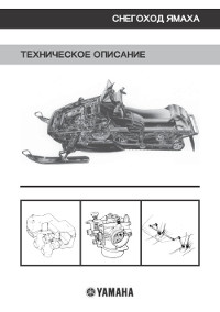
Описание конструкции снегохода Yamaha.
- Год издания: —
- Страниц: 65
- Формат: PDF
- Размер: 6,9 Mb
Руководство на английском языке по техническому обслуживанию и ремонту снегохода Yamaha BR250F.
- Год издания: 1981
- Страниц: 191
- Формат: PDF
- Размер: 8,7 Mb

Руководство по эксплуатации и техническому обслуживанию снегоходов Yamaha BR250TG и Yamaha VK540EG.
- Год издания: 2001
- Страниц: 88
- Формат: PDF
- Размер: 8,7 Mb
Дополнение к руководству по техническому обслуживанию и ремонту снегохода Yamaha ET300E.
- Год издания: 1980
- Страниц: 8
- Формат: PDF
- Размер: 790 Kb
Сборник руководств по эксплуатации и техническому обслуживанию снегоходов Yamaha FX Nytro моделей FX10/RFX10 различных модификаций.
- Год издания: 2007-2012
- Страниц: 94/118/122
- Формат: PDF
- Размер: 32,0 Mb
Сборник руководств на английском языке по эксплуатации и техническому обслуживанию снегоходов Yamaha FX Nytro модели FX10 различных модификаций.
- Год издания: 2007-2011
- Страниц: 92/104
- Формат: PDF
- Размер: 18,5 Mb
Руководство на английском языке по техническому обслуживанию и ремонту снегохода Yamaha FX Nytro модели FX10 различных модификаций.
- Год издания: 2007
- Страниц: 410
- Формат: PDF
- Размер: 13,5 Mb

Руководство по эксплуатации и техническому обслуживанию снегоходов Yamaha MM700/VT700/VX700ER.
- Год издания: 2001
- Страниц: 100
- Формат: PDF
- Размер: 9,2 Mb
Сборник руководств на английском языке по эксплуатации и техническому обслуживанию снегоходов Yamaha MM600/MM700/SX600/VT600/VT700/VX600/VX700 различных модификаций.
- Год издания: 1998-2002
- Страниц: —
- Формат: PDF
- Размер: 32,0 Mb
Сборник руководств по эксплуатации и техническому обслуживанию снегоходов Yamaha PZ50/RPZ50 Venture различных модификаций.
- Год издания: 2006/2012
- Страниц: 110/120
- Формат: PDF
- Размер: 11,7 Mb
Сборник руководств на английском языке по эксплуатации и техническому обслуживанию снегоходов Yamaha PZ50 Phazer, Venture различных модификаций.
- Год издания: 2006-2009
- Страниц: 88/92/98/104
- Формат: PDF
- Размер: 21,6 Mb
Сборник руководств на английском языке по техническому обслуживанию и ремонту снегохода Yamaha PZ50 Phazer, Venture различных модификаций.
- Год издания: 2006-2007
- Страниц: 424/114
- Формат: PDF
- Размер: 21,2 Mb
Руководство на английском языке по техническому обслуживанию и ремонту снегоходов Yamaha PZ500C и Yamaha VT500XLC.
- Год издания: 1998
- Страниц: 209
- Формат: PDF
- Размер: 6,0 Mb
Руководство на английском языке по эксплуатации и техническому обслуживанию снегоходов Yamaha PZ 500D/PZ500MLD/VT500XLD.
- Год издания: 1999
- Страниц: 83
- Формат: PDF
- Размер: 2,4 Mb
Сборник руководств по эксплуатации и техническому обслуживанию снегоходов Yamaha RS10/RS90/RSG90/RST90 RS Vecror, RS Venture различных модификаций.
- Год издания: 2004/2011/2012
- Страниц: 100/108/162
- Формат: PDF
- Размер: 31,0 Mb
Сборник руководств на английском языке по эксплуатации и техническому обслуживанию снегоходов Yamaha RS90/RSG90/RST90 RS Vector, RS Venture различных модификаций.
- Год издания: 2004-2011
- Страниц: —
- Формат: PDF
- Размер: 63,5 Mb
Сборник руководств на английском языке по техническому обслуживанию и ремонту снегоходов Yamaha RS90/RSG90/RST90 RS Venture различных модификаций.
- Год издания: 2004/2006/2008
- Страниц: 414/202/299
- Формат: PDF
- Размер: 37,1 Mb
Сборник руководств по эксплуатации и техническому обслуживанию снегоходов Yamaha RX10/RXW10 Apex различных модификаций.
- Год издания: 2001-2012
- Страниц: —
- Формат: PDF
- Размер: 28,6 Mb
Сборник руководств на английском языке по эксплуатации и техническому обслуживанию снегоходов Yamaha RX90/RXW90 Apex различных модификаций.
- Год издания: 2002-2010
- Страниц: —
- Формат: PDF
- Размер: 48,2 Mb
Руководство на английском языке по эксплуатации и техническому обслуживанию снегоходов Yamaha SRX700G.
- Год издания: 2001
- Страниц: 84
- Формат: PDF
- Размер: 6,6 Mb

Сборник руководств по эксплуатации и техническому обслуживанию снегоходов Yamaha SXV60/SXV70/VT60/VT70 различных модификаций.
- Год издания: 2003
- Страниц: 113/127
- Формат: PDF
- Размер: 10,5 Mb
Сборник руководств на английском языке по эксплуатации и техническому обслуживанию снегоходов Yamaha SXV60/SXV70/VT60/VT70 различных модификаций.
- Год издания: 2001-2005
- Страниц: —
- Формат: PDF
- Размер: 48,3 Mb

Сборник руководств по эксплуатации и техническому обслуживанию снегоходов Yamaha VK10/VK10D RS Viking.
- Год издания: 2007/2012
- Страниц: 98/108
- Формат: PDF
- Размер: 15,6 Mb
Сборник руководств на английском языке по эксплуатации и техническому обслуживанию снегоходов Yamaha VK10L и Yamaha VK10X.
- Год издания: 2005/2007
- Страниц: 98/88
- Формат: PDF
- Размер: 7,9 Mb
Дополнение к руководству по техническому обслуживанию и ремонту снегоходов Yamaha VK10L/VK10W.
- Год издания: 2005-2006
- Страниц: 360/103
- Формат: PDF
- Размер: 12,2 Mb

Руководство по эксплуатации и техническому обслуживанию снегоходов Yamaha VK540E/VK540EC.
- Год издания: 2012
- Страниц: 82
- Формат: PDF
- Размер: 3,2 Mb

Сборник руководств на английском языке по эксплуатации и техническому обслуживанию снегоходов Yamaha VK540EG/VK540EK.
- Год издания: 2001/2004
- Страниц: 76
- Формат: PDF
- Размер: 4,8 Mb

Руководство на английском языке по техническому обслуживанию и ремонту снегохода Yamaha VK540EK.
- Год издания: 2000
- Страниц: 211
- Формат: PDF
- Размер: 4,9 Mb
Руководство по эксплуатации и техническому обслуживанию снегохода Yamaha VT500XL.
- Год издания: 2001
- Страниц: 84
- Формат: PDF
- Размер: 8,2 Mb
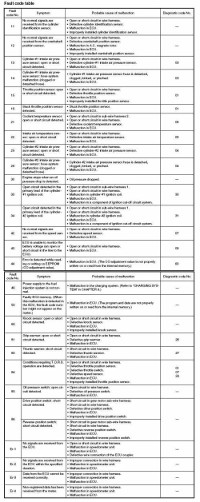
Коды неисправностей Yamaha.
- Год издания: —
- Страниц: 11
- Формат: JPG
- Размер: 1,7 Mb

-
ВАЖНО: Снегоход попадет под категорию B? подробнее…
-
Форумы
-
Снегоходы
-
Снегоходы зарубежного производства
-
Yamaha
Adrenaline Drive: Новости и полезная информация из мира техники для активного отдыха.
Частые вопросы и техническая документация по снегоходам Yamaha
COMPOSIT
Гусеницы для снегоходов и спецтехники
Adrenaline Drive
Новости и полезная информация из мира техники для активного отдыха.
Разборка снегоходов
б/у запчасти
Предложения от надежных партнеров
Техника и запчасти
Фильтры
Фильтры

Мануал Проф 2
- Саня13RUS
- 6 Мар 2023
- Ответы
- 0
- Просмотры
- 280
6 Мар 2023
Саня13RUS

Yamaha venture MP и Yamaha Fazer Руководства пользователя и ремонт
- MAD
- 23 Мар 2008
- Ответы
- 11
- Просмотры
- 27K
11 Янв 2023
Alex069
A

Руководство пользователя Yamaha VK10
- Сергей Хардиков
- 17 Июн 2008
- Ответы
- 19
- Просмотры
- 20K
14 Дек 2022
v_el
V
Мануал YAMAHA APEX 2013
- Саня13RUS
- 19 Мар 2020
- Ответы
- 5
- Просмотры
- 6K
21 Ноя 2022
скутер
С
C
Service Manual Yamaha SnowMobiles (кладем и пользуемся)
- Camarat
- 1 Ноя 2008
- Ответы
- 21
- Просмотры
- 21K
17 Сен 2022
vadim29
V

Сервис мануал на Ямаха VK540 V
- sanich
- 9 Фев 2021
- Ответы
- 1
- Просмотры
- 4K
13 Мар 2022
sanich
Цепи и звёздочки КПП YAMAHA подбор.
- Саня13RUS
- 28 Фев 2022
- Ответы
- 0
- Просмотры
- 2K
28 Фев 2022
Саня13RUS

Смодиагностика PHAZER и MULTI PURPOSE
- amorfix
- 9 Фев 2021
- Ответы
- 8
- Просмотры
- 5K
21 Фев 2022
Multipurpose_elproblema
M

Сервисный бюллетень MRS07005 по затруднённому холодному запуску Multipurpose/Phazer 2006-2008 г.в.
- Gloster
- 16 Дек 2021
- Ответы
- 5
- Просмотры
- 2K
23 Янв 2022
Gloster
З
Мануал на ямаха вайпер
- зетмен
- 7 Дек 2021
- Ответы
- 0
- Просмотры
- 2K
7 Дек 2021
зетмен
З

Ищу мануал Yamaha Venture TF 2010г.в.
- galeon77
- 7 Июн 2011
- Ответы
- 15
- Просмотры
- 9K
19 Ноя 2021
Key_help89
K

FAQ Yamaha Nytro XTX
- SouLCoRe
- 11 Окт 2014
2
- Ответы
- 29
- Просмотры
- 48K
4 Ноя 2021
Alex069
A

YAMAHA Professional VK10D
- ВИТ
- 18 Апр 2016
- Ответы
- 7
- Просмотры
- 12K
21 Янв 2021
Диматет
Д
S
Руководство по ремонту Ямаха профессионал
- Syvor
- 17 Май 2019
- Ответы
- 11
- Просмотры
- 8K
21 Янв 2021
Диматет
Д

Yamaha Bravo 250T каталог запчастей и руководство по ремонту
- Alex77
- 5 Мар 2008
- Ответы
- 5
- Просмотры
- 23K
20 Янв 2021
Романов А.В.
Р
C
Руководство и эксплуатация снегохода Yamaha VK 540 III
- Camarat
- 11 Ноя 2008
2
- Ответы
- 48
- Просмотры
- 122K
7 Фев 2020
алекссан
А

Yamaha VK 540 сервис мануал на русском
- Kupr
- 21 Янв 2019
- Ответы
- 4
- Просмотры
- 11K
31 Дек 2019
Kupr
V
Нужен мануал YAMAHA VENTURA 700 2000-2003 года
- Vlk
- 19 Дек 2019
- Ответы
- 0
- Просмотры
- 3K
19 Дек 2019
Vlk
V

Yamaha Venture TF RS10SUV Руководство пользователя и Servis Manual
- raw
- 20 Дек 2010
- Ответы
- 5
- Просмотры
- 17K
10 Фев 2019
Dimankrep


Yamaha RS Veture GT/TF (FAQ)
- mer_ik
- 21 Окт 2015
- Ответы
- 3
- Просмотры
- 7K
17 Янв 2019
Roman4ik
R
Войдите или зарегистрируйтесь для ответа.
COMPOSIT
Гусеницы для снегоходов и спецтехники
Adrenaline Drive
Новости и полезная информация из мира техники для активного отдыха.
Разборка снегоходов
б/у запчасти
Предложения от надежных партнеров
Техника и запчасти
-
Форумы
-
Снегоходы
-
Снегоходы зарубежного производства
-
Yamaha
![]()
4-я Красноармейская, 2А
Санкт-Петербург, 190005
Email: info@lenmoto.ru
Телефон: +7 (921) 930-81-18
Телефон: +7 (911) 928-08-06
Компания ЛенМото
Запчасти, аксессуары, экипировка, тюнинг для мотоциклов, скутеров, квадроциклов, снегоходов, багги, гидроциклов, катеров и лодочных моторов.
Подпишитесь на наши новости
Подписаться
|
Title |
File Size |
Download Links |
|
Yamaha BR250 Bravo Snowmobile Service Manual.pdf |
10.3Mb |
Download |
|
Yamaha BR250 Parts Catalog.rar |
8.3Mb |
Download |
|
Yamaha BR250F Service Manual.pdf |
10.8Mb |
Download |
|
Yamaha BR250TG/VK540EG Owner’s Manual.pdf |
8.7Mb |
Download |
|
Yamaha EC340E Supplementary Service Manual.pdf |
892.9kb |
Download |
|
Yamaha ET300E Supplementary Service Manual.pdf |
790.2kb |
Download |
|
Yamaha ET410 Parts Catalog.rar |
4.1Mb |
Download |
|
Yamaha FX Nytro Owner`s Manual.rar |
18.5Mb |
Download |
|
Yamaha FX Nytro Service Manual.pdf |
13.5Mb |
Download |
|
Yamaha FX/FX10/RFX10 Owner’s Manual.rar |
32Mb |
Download |
|
Yamaha FX10 Parts Catalog.rar |
13.2Mb |
Download |
|
Yamaha MM600/MM700 Parts Catalog.rar |
6.2Mb |
Download |
|
Yamaha MM600/MM700/MX600/VT600/VT700/VX600/VX700 Owner`s Manual.rar |
32Mb |
Download |
|
Yamaha MM700/VT700/VX700ER Owner`s Manual.pdf |
9.2Mb |
Download |
|
Yamaha Phazer Venture Lite PZ50MTA 2011 Supplementary Service Manual.pdf |
6.4Mb |
Download |
|
Yamaha PZ-series Parts Catalog.rar |
30Mb |
Download |
|
Yamaha PZ50 Owner`s Manual.rar |
11.7Mb |
Download |
|
Yamaha PZ50 Phazer, Venture Owner`s Manual.rar |
21.6Mb |
Download |
|
Yamaha PZ50 Service Manual.rar |
21.2Mb |
Download |
|
Yamaha PZ500/VT500 Owner`s Manual.pdf |
2.4Mb |
Download |
|
Yamaha PZ500C/VT500XLC Service Manual.rar |
6Mb |
Download |
|
Yamaha RS10/RS90/RSG90/RST90 Owner`s Manual.rar |
31Mb |
Download |
|
Yamaha RS90 Parts Catalog.rar |
7.6Mb |
Download |
|
Yamaha RS90/RSG90/RST90 RS Vector, RS Venture Owner`s Manual.rar |
63.5Mb |
Download |
|
Yamaha RS90/RSG90/RST90 RS Venture Service Manual.rar |
37.1Mb |
Download |
|
Yamaha RS90L Owner`s Manual.pdf |
5.8Mb |
Download |
|
Yamaha RSG90 Parts Catalog.rar |
3.5Mb |
Download |
|
Yamaha RST90 Parts Catalog.rar |
11.9Mb |
Download |
|
Yamaha RX-1 Service Manual.pdf |
18.8Mb |
Download |
|
Yamaha RX10 Parts Catalog.rar |
28Mb |
Download |
|
Yamaha RX10/RXW10 Owner`s Manual.rar |
28.6Mb |
Download |
|
Yamaha RX10LTGTYL Service Manual.pdf |
32.7Mb |
Download |
|
Yamaha RX90/RXW90 Apex Owner`s Manual.rar |
48.2Mb |
Download |
|
Yamaha RXW10 Parts Catalog.rar |
5.1Mb |
Download |
|
Yamaha SL292C 1971 Service Manual.pdf |
26Mb |
Download |
|
Yamaha Snowmobile Design Description.pdf |
6.9Mb |
Download |
|
Yamaha snowmobile fault codes list.rar |
1.7Mb |
Download |
|
Yamaha SRX700 Parts Catalog.rar |
5.9Mb |
Download |
|
Yamaha SRX700 Service Manual.pdf |
7.4Mb |
Download |
|
Yamaha SX500/600/700 Parts Catalog.rar |
10.7Mb |
Download |
|
Yamaha SXV-VT owner`s manual.rar |
48.3Mb |
Download |
|
Yamaha SXV60/SXV70/VT60/VT70 Owner`s Manual.rar |
48.3Mb |
Download |
|
Yamaha SXV70 Parts Catalog.rar |
14.6Mb |
Download |
|
Yamaha SXV70ERJ Owner’s Manual.pdf |
9.6Mb |
Download |
|
Yamaha VK10/VK10D RS Viking Owner`s Manual.rar |
15.6Mb |
Download |
|
Yamaha VK10/VK540 Parts Catalog.rar |
22.7Mb |
Download |
|
Yamaha VK10L/ Yamaha VK10X Owner`s Manual.rar |
7.9Mb |
Download |
|
Yamaha VK540EG/VK540EK Owner`s Manual.rar |
4.8Mb |
Download |
|
Yamaha VK540EK Service Manual.pdf |
4.9Mb |
Download |
|
Yamaha VT Parts Catalog.rar |
65.9Mb |
Download |
|
Yamaha VT500XL Owner`s Manual.pdf |
8.2Mb |
Download |
|
Yamaha VT700F Service Manual.pdf |
13.1Mb |
Download |
|
Yamaha VX500/600/700 Parts Catalog.rar |
21.2Mb |
Download |
|
Yamaha VX500SXBC Service Manual.pdf |
2.3Mb |
Download |
Yamaha is one of the oldest corporations in the world producing musical instruments, sound equipment, sports equipment, etc.
Yamaha began to produce snowmobiles from the beginning of the 60s of the last century, and already in 1968 the mass production of this equipment began. The company’s products were oriented to the
US and Canada markets.
A feature of Yamaha snowmobiles is that their motor was borrowed from motorcycles, due to this, snowmobiles received additional aggression. Every year, Yamaha increased
production, and by 1983, 500 thousand units of equipment had rolled off its conveyors, and by 1997, the line of one million snowmobiles had been overcome.
Production facilities are located in both Japan and the United States. Yamaha is considered the most successful manufacturer of snowmobiles, if we consider their financial performance. The
Japanese manufacturer worldwide employs more than 40 thousand employees. The domestic market of Japan in the total share of sales occupies only 12%, the remaining 88% is export.
The modern market divides snowmobiles into:
- Utilitarian;
- Tourist;
- Sports;
- Mountain.
Japanese utilitarian Yamaha snowmobiles are very popular in Russia. Especially Yamaha RS Viking Professional and Yamaha VK 540. This is a classic of the genre. If you need a
reliable utilitarian snowmobile, the first thing that comes to mind is, of course, Viking.
The latest VK540 IV has even greater cross-country ability in deep snow, carrying capacity, high-torque and endurance. At the same time, it is economical and highly reliable.
Everything in VK540 IV is aimed at giving you maximum pleasure from overcoming the virgin snow. The heart of the snowmobile is the time-tested 535cc 2-cylinder 2-stroke Yamaha engine, powerful
and tough. It is reliable and easy to maintain, and in combination with a 2-speed transmission expands the capabilities of the snowmobile. Innovatively designed wide skis with an optimized skate
profile provide excellent deep snow maneuverability and handling.
Lightweight and durable, the wide Camoplast Ripsaw Full Block ™ caterpillar is known for its exceptional cross-country ability. A new torsion rear suspension was used, leading drive wheels of the
track with external gearing. Electric heating of the handlebars of the steering wheel and the trigger of «gas», a high windshield were installed. Convenient seatpost and spacious trunk, 2-seater
seat, spacious footrests with non-slip surface. With VK540IV, work has never been so much fun!
Yamaha Japanese snowmobiles are always among the best in the world. In the 2011 lineup, 3 models were presented:
- Snowmobile Yamaha RS Venture TF
- Snowmobile Yamaha RS Venture GT
- Snowmobile Yamaha Venture Multi Purpose
Yamaha sports snowmobiles in 2011 were represented by only three models: FX Nytro R-TX, FX Nytro X-TX and APEX X-TX. All these models are suitable for fast driving along natural
trails and are of the rough trail type. It is important to recall that all of these models are 4-stroke. This is the general policy of Yamaha on environmentally friendly technology. Let us focus
on the new product of 2011 for the Russian market — the Yamaha APEX X-TX model. This is the first snowmobile to feature an EPS electric power steering system that sets new standards for handling
and stability. This model is equipped with a modified four-cylinder engine with an EXUP exhaust system and a fuel injection system. These improvements were made in order to significantly increase
peak power and torque at low and medium ranges of engine speed. A long 144 ”/ 3658mm track, new front suspension geometry, Dual Shock® suspensions and wide skis make it easy to cross any trails.

-
Page 1
FX NYTRO RTX / XTX / RTX SE MTX SE 153/162 2010 Service Manual LIT-12618-FX-01… -
Page 407
WIRING DIAGRAM FX10/FX10RT/FX10RTR/FX10RTRA/FX10MT/FX10MTR/FX10MTRA 2008 8GL-0F001-00/8HA-0F001-00 È É (BLACK) (BLACK) (GRAY) (GRAY) COOLANT OIL PRESSURE TAIL/BRAKE FUEL INJECTION SYSTEM WIRE WIRE WIRE SPEEDOMETER WIRE REVERSE SWITCH WIRE WIRE HARNESS SWITCH LIGHT TEMPERATURE SUB-WIRE HARNESS HARNESS HARNESS HARNESS UNIT SUB-LEAD HARNESS SUB-WIRE HARNESS HARNESS SUB-LEAD SUB-LEAD… -
Page 409
2009 SUPPLEMENTARY SERVICE MANUAL FX10Y FX10RTRY FX10RTRSY FX10XTY FX10MTRY LIT-12618-02-80 8GL-28197-11… -
Page 410
8GL-28197-10 (LIT-12618-02-69) ing or repairing the snowmobile. NOTICE NOTICE This manual was written by the Yamaha Motor A NOTICE indicates special precautions that must Company primarily for use by Yamaha dealers be taken to avoid damage to the snowmobile. and their qualified mechanics. It is not possible to put an entire mechanic’s education into one… -
Page 411
MAJOR SPECIFICATIONS (CHASSIS) Model FX10Y FX10RTRY FX10RTRSY FX10XTY FX10MTRY Model code number 8GL3 8HB5 8HK1 8HL1 8HA9 Class Rough trail Crossover Mountain 3,648 mm 3,886 mm Track length 3,072 mm (121 in) (144 in) (153 in) Next generation FX-style Independent Front suspension independent double wishbone double wishbone… -
Page 412
ILLUSTRATED SYMBOLS (Refer to the illustration) Illustrated symbols are designed as thumb tabs to indicate the chapter’s number and content. General information Periodic inspection and adjustment Chassis Power train Engine Cooling system Fuel injection system Electrical Specifications Illustrated symbols are used to iden- tify the specifications which appear. -
Page 415
CONTENTS GENERAL INFORMATION INFO PERIODIC INSPECTION AND INSP ADJUSTMENT CHASSIS CHAS POWER TRAIN POWR ENGINE COOLING SYSTEM COOL FUEL INJECTION SYSTEM ELECTRICAL ELEC SPECIFICATIONS SPEC… -
Page 416: Table Of Contents
CHAPTER 1. CHAPTER 8. GENERAL INFORMATION ELECTRICAL SPECIAL TOOLS ………. 1 LIGHTING SYSTEM ……..66 FOR CHASSIS SERVICE……1 CIRCUIT DIAGRAM ……..66 SIGNAL SYSTEM ……..68 CHAPTER 2. CIRCUIT DIAGRAM ……..68 PERIODIC INSPECTION AND ADJUSTMENT GRIP WARMER SYSTEM ……70 GRIP WARMER AND INTRODUCTION ………..
-
Page 417: General Information
SPECIAL TOOLS INFO GENERAL INFORMATION SPECIAL TOOLS Some special tools are necessary for a completely accurate tune- up and assembly. Using the correct special tool will help prevent damage that can be caused by the use of improper tools or impro- vised techniques.
-
Page 418: Periodic Maintenance Chart For The Emission Control System
Fuel line • Replace if necessary. • Check synchronization. Fuel injection • Adjust if necessary. • Check for leakage. Exhaust system • Tighten or replace gasket if necessary. * It is recommended that these items be serviced by a Yamaha dealer.
-
Page 419: General Maintenance And Lubrication Chart
• Check condition. Battery • Charge if necessary. * It is recommended that these items be serviced by a Yamaha dealer. Brake system: • After disassembling the master cylinder or caliper cylinder, always change the brake fluid. Regu- larly check the brake fluid level and add fluid if necessary.
-
Page 420
INSP LUBRICATION LUBRICATION Rear suspension 1. Use a grease gun to inject grease into the nipples. 2. Apply grease to the pivoting parts. Recommended lubricant: ESSO Beacon 325 Grease or Aeroshell Grease #7A FX10Y/FX10RTRY/FX10RTRSY FX10XTY FX10MTRY Nipple Nipple (both sides) -
Page 421
INSP CLUTCH TUNING CLUTCH High altitude Specifications Model: FX10Y/FX10RTRY ~ 800 m 600 ~ 1,400 m 1,200 ~ 2,000 m 1,800 ~ 2,600 m 2,400 ~ 3,000 m Elevation (~ 2,500 ft) (2,000 ~ 4,500 ft) (4,000 ~ 6,500 ft) (6,000 ~ 8,500 ft) (8,000 ~ 10,000 ft) ←… -
Page 422
INSP CLUTCH Specifications Model: FX10RTRSY ~ 800 m 600 ~ 1,400 m 1,200 ~ 2,000 m 1,800 ~ 2,600 m 2,400 ~ 3,000 m Elevation (~ 2,500 ft) (2,000 ~ 4,500 ft) (4,000 ~ 6,500 ft) (6,000 ~ 8,500 ft) (8,000 ~ 10,000 ft) ←… -
Page 423
INSP CLUTCH Specifications Model: FX10XTY ~ 800 m 600 ~ 1,400 m 1,200 ~ 2,000 m 1,800 ~ 2,600 m 2,400 ~ 3,000 m Elevation (~ 2,500 ft) (2,000 ~ 4,500 ft) (4,000 ~ 6,500 ft) (6,000 ~ 8,500 ft) (8,000 ~ 10,000 ft) ←… -
Page 424
INSP CLUTCH Specifications Model: FX10MTRY ~ 800 m 600 ~ 1,400 m 1,200 ~ 2,000 m 1,800 ~ 2,600 m 2,400 ~ 3,000 m Elevation (~ 2,500 ft) (2,000 ~ 4,500 ft) (4,000 ~ 6,500 ft) (6,000 ~ 8,500 ft) (8,000 ~ 10,000 ft) ←… -
Page 425
INSP CLUTCH/GEAR SELECTION The clutch may require tuning depending upon where the snowmobile will be operated and the desired handling characteristics. The clutch can be tuned by changing the engagement and shifting speeds. Clutch engagement speed is defined as the engine speed at which the snowmobile first begins to move from a complete stop. -
Page 426
INSP GEAR SELECTION Chain and sprocket part number Parts name Teeth & links Parts no. Standard 18 teeth 8FA-17682-80 19 teeth 8FA-17682-90 20 teeth 8FA-17682-00 FX10MTRY FX10Y/FX10RTRY/ Drive sprocket 21 teeth 8FA-17682-10 FX10RTRSY/ FX10XTY 22 teeth 8FA-17682-20 23 teeth 8FA-17682-30 24 teeth 8FA-17682-40 38 teeth… -
Page 427: Gear Selection
INSP GEAR SELECTION Secondary sheave spring Spring rate Preload Wire Free Outside No. of Part No. N•mm/rad N/mm (kg/mm) Color gauge length diameter Standard coils (kg•mm/rad) (lb/in) mm (in) mm (in) mm (in) 90508-500B1 6003 (613) 6.2 (0.63), 35.40 Brown 5.0 (0.197) 5.19 75 (2.95)
-
Page 428
INSP GEAR SELECTION Primary spring Spring identification color code Actual coloring Spring Spring rate Wire Outside Free identification Preload No. of Parts No. N/mm gauge diameter length Standard color code N (kg) coils (kg/mm) mm (in) mm (in) mm (in) Actual coloring Blue-Blue-Blue 90501-550A2… -
Page 429
INSP GEAR SELECTION Clutch weight Weight g (oz) Parts No. without bush Shape & ID mark Standard and rivets 8BU-17605-20 45.41 (1.603) 8DJ-17605-00 37.77 (1.333) 8ES-17605-00 54.63 (1.928) 8FA-17605-10 63.81 (2.252) 8FN-17605-00 75.28 (2.657) 8FP-17605-00 67.81 (2.394) 8FS-17605-00 65.52 (2.313) FX10MTRY FX10Y/FX10RTRY/ 8GL-17605-00… -
Page 430
INSP GEAR SELECTION Weight rivets Length Weight Parts No. Material Standard Effects mm (in) g (oz) IN: FX10Y/FX10RTRY/FX10RTRSY Increased CENTER: FX10Y/FX10RTRY/FX10RTRSY/ 90261-06033 Steel 17.2 (0.677) 4.5 (0.159) force FX10XTY OUT: FX10XTY 3.6 (0.127) 90269-06006 Steel 17.2 (0.677) with hole 90261-06034 Steel 13.9 (0.547) 3.6 (0.127) -
Page 431
INSP GEAR SELECTION Rollers I.D. 9 mm (0.354 in) Roller with Outside Bushing type Identification mark bushing part diameter Standard Effects (P/N) (Width) number mm (in) Grooved & Machined VESPEL Increased TP-8549 force 8FG-17624-00 14.5 (0.57) (14.6 mm [0.57 in]) 90386-09001 Grooved VESPEL… -
Page 432
INSP FRONT SUSPENSION FRONT SUSPENSION Spring preload 1. Adjust: • Spring preload Adjustment steps: • Loosen the locknut • Turn the spring seat in or out. FX10Y/FX10XTY Standard Spring seat Short ← → Long distance Hard ← → Soft Preload Min. -
Page 433
INSP FRONT SUSPENSION Rebound damping force adjustment The rebound damping force can be adjusted by turning the adjusting knob FX10Y/FX10XTY 20 clicks out 11 clicks out 3 clicks out Adjusting knob Minimum Standard Maximum position → Direction Direction *← Rebound Soft ←… -
Page 434: Front Suspension
INSP FRONT SUSPENSION Compression damping force adjustment The compression damping force can be adjusted by turning the adjusting knob FX10Y/FX10XTY 12 clicks out 6 clicks out 2 clicks out Adjusting knob Minimum Standard Maximum position → Direction Direction *← Rebound Soft ←…
-
Page 435
INSP FRONT SUSPENSION Air pressure adjustment (FX10RTRY/FX10RTRSY) NOTICE The left and right shock absorber air pres- sure must be set to the same setting. Uneven settings can cause poor handling and loss of stability. This snowmobile is equipped with FOX shock absorbers as standard equipment. -
Page 436
INSP FRONT SUSPENSION NOTICE Do not overtighten the connector onto the air valve as this will damage the connector seal. If the shock absorber has no air pressure, the gauge reading will be zero. • To increase the air pressure, operate the pump a few times. -
Page 437
INSP FRONT SUSPENSION NOTICE Do not exceed 1,034 kPa (10.3 kg/cm², 150 psi). • Install the air valve cap. If the front suspension bottoms too easily or rolls too much during cornering, increase the air pressure by 34 kPa (0.3 kg/cm², 5 psi). If the suspension is too firm and you want a more compliant ride, decrease the air pressure by 34 kPa (0.3 kg/cm², 5 psi). -
Page 438
INSP REAR SUSPENSION REAR SUSPENSION Stopper band 1. Adjust: • Stopper band length NOTICE Make sure the left and right rear suspen- sion stopper bands are adjusted evenly. This adjustment affects the handling character- istics of the snowmobile. Adjustment steps: •… -
Page 439
INSP REAR SUSPENSION Choosing other settings: NOTICE The standard settings work well under most general riding conditions. The sus- pension can be adjusted to work better in one condition, but only at the expense of another. Keep this in mind when you adjust the suspension. -
Page 440
INSP REAR SUSPENSION Spring preload 1. Adjust: • Spring preload Adjustment step: Front side • Loosen the locknut • Turn the spring seat in or out. FX10Y Standard Spring seat Short ← → Long distance Hard ← → Soft Preload Min. -
Page 441
INSP REAR SUSPENSION Rear side • Turn the spring preload adjuster proper position by the tool Spring preload adjuster position Spring preload Soft Medium Hard Standard WARNING Always adjust both spring preload (left and right) to the same setting. Uneven adjust- ment can cause poor handling and loss of stability. -
Page 442
INSP REAR SUSPENSION Rebound damping force (Rear side) (FX10RTRY/FX10RTRSY) The damping force can be adjusted by turning the adjusting dial 20 clicks out 11 clicks out 3 clicks out Adjusting dial Minimum Standard Maximum position → Direction Direction *← Rebound Soft ←… -
Page 443
INSP REAR SUSPENSION Compression damping force (Front side) (FX10RTRY/FX10RTRSY) The compression damping force can be adjusted by turning the adjusting screw 12 clicks out 6 clicks out 2 clicks out Adjusting screw Minimum Standard Maximum position → Direction Direction *← Compres- sion Soft ←… -
Page 444
INSP REAR SUSPENSION Compression damping force (Rear side) (FX10Y/FX10RTRY/FX10XTY/FX10MTRY) The compression damping force can be adjusted by turning the adjusting screw 12 clicks out 6 clicks out 2 clicks out Adjusting screw Minimum Standard Maximum position → Direction Direction *← Compres- sion Soft ←… -
Page 445
INSP REAR SUSPENSION Compression damping force (Rear side) (FX10RTRSY) Slow compression damping The slow compression damping force can be adjusted by turning the adjusting screw 16 clicks out 6 clicks out 1 clicks out Adjusting screw Minimum Standard Maximum position →… -
Page 446
INSP REAR SUSPENSION Compression damping force (Rear side) (FX10RTRSY) Fast compression damping The fast compression damping force can be adjusted by turning the adjusting bolt 4 turns out 2 turns out 0 turn out Adjusting screw Minimum Standard Maximum position →… -
Page 447
INSP REAR SUSPENSION Control rod (FX10XTY/FX10MTRY) 1. Adjust: • Control rod stroke NOTICE Make sure the adjusting nut ends are set at the same position on each side. Adjustment steps: • Loosen the locknut • Turn the adjusting nut in or out to adjust the control rod stroke. -
Page 448
CHAS COVERS CHASSIS COVERS 4 Nm (0.4 m•kg, 2.9 ft•lb) FX10Y Order Job/Part Q’ty Remarks Covers removal Remove the parts in the order listed below. Windshield Shroud Side cover (left and right) Main switch coupler Disconnect. Auxiliary DC jack coupler Disconnect. -
Page 449
CHAS COVERS 7 Nm (0.7 m•kg, 5.1 ft•lb) 23 Nm (2.3 m•kg, 17 ft•lb) Order Job/Part Q’ty Remarks Drive guard pin Drive guard Lower cover (left and right) Storage pouch Reflector Front cover Front bumper For installation, reverse the removal procedure. -
Page 450
CHAS STEERING STEERING INSTALLATION 1. Install: • Tie rod • Locknuts • Joints Tie rod part Tie rod number length length 8HK-23831-00 (FX10Y/ 527.0 mm 458.5 mm FX10RTRY/ (20.75 in) (18.05 in) FX10RTRSY/ FX10XTY) 8HA-23831-00 518.0 mm 449.5 mm (FX10MTRY) (20.39 in) (17.70 in) FX10Y/FX10RTRY/FX10RTRSY/FX10XTY… -
Page 451
CHAS STEERING 3. Install: • Steering shaft • Locknuts • Joints Steering shaft Shaft part number length length 232.2 mm 174.2 mm 8GL-23821-00 (9.14 in) (6.86 in) NOTICE Always use new cotter pin. Steering shaft and pivot arm nut: 35 Nm (3.5 m•kg, 25 ft•lb) Steering shaft and steering column nut: 35 Nm (3.5 m•kg, 25 ft•lb) -
Page 452
CHAS STEERING 5. Adjust: • Skis Adjustment steps: • Temporarily install the handlebar. • Hold the handlebar straight and check that the skis are at right angles to the handlebar. • Install the steering linkage alignment plate To install the steering linkage alignment plate, turn the handlebar completely to the right, position the plate behind the steering column , and then fit the steering column into the… -
Page 453
CHAS STEERING 6. Install: For FX10RTRY/FX10RTRSY • Steering joint • Steering joint holders • Install the steering joint with the shallow cut- facing forward. • Align the centerline of the steering joint with the centerline of the steering column shown in the illustration. •… -
Page 454
CHAS STEERING 8. Install: FX10Y/FX10RTRY/FX10RTRSY/ FX10XTY • Wind deflector bracket holder • Wind deflector bracket Align the end of the wind deflector bracket with the punch mark on the handlebar. 9. Install: FX10Y/FX10RTRY/FX10RTRSY/ FX10XTY • Handlebar protector Install the handlebar cover , making sure not to pinch the cables, leads, etc. -
Page 455
CHAS FRONT SUSPENSION FRONT SUSPENSION FX10Y/FX10RTRY/FX10RTRSY/FX10XTY 28 Nm (2.8 m•kg, 20 ft•lb) 34 Nm (3.4 m•kg, 24 ft•lb) 45 Nm (4.5 m•kg, 32 ft•lb) 55 Nm (5.5 m•kg, 41 ft•lb) 65 Nm (6.5 m•kg, 47 ft•lb) 90 Nm (9.0 m•kg, 65 ft•lb) Order Job/Part Q’ty… -
Page 456
CHAS FRONT SUSPENSION 28 Nm (2.8 m•kg, 20 ft•lb) 34 Nm (3.4 m•kg, 24 ft•lb) 45 Nm (4.5 m•kg, 32 ft•lb) 55 Nm (5.5 m•kg, 41 ft•lb) 65 Nm (6.5 m•kg, 47 ft•lb) 90 Nm (9.0 m•kg, 65 ft•lb) Order Job/Part Q’ty Remarks… -
Page 457
CHAS FRONT SUSPENSION REMOVAL WARNING Securely support the snowmobile so that there is no danger of it falling over. Place the snowmobile on a suitable stand so that the ski is elevated. 1. Remove: • Ski Refer to “SKI” in chapter 3. 2. -
Page 458
CHAS FRONT SUSPENSION 7. Remove: • Lower arm ball joint Ball joint remover 55 mm 25 mm YS-01537 (2.17 in) (0.98 in) When installing the ball joint remover, install the attachment to bottom of the lower arm and, install the remover attachment above the lower arm ball joint. -
Page 459
CHAS FRONT SUSPENSION 3. Install: • Knuckle 4. Install: • Tie rod • Upper arm ball joint hexagon bolt • Lower arm ball joint bolt Tie rod nut 28 Nm (2.8 m•kg, 20 ft•lb) Upper arm ball joint hexagon bolt 55 Nm (5.5 m•kg, 41 ft•lb) Lower arm ball joint nut 65 Nm (6.5 m•kg, 47 ft•lb) -
Page 460: Power Train
POWR SLIDE RAIL SUSPENSION POWER TRAIN SLIDE RAIL SUSPENSION FX10RTRSY 60 Nm (6.0 m•kg, 43 ft•lb) 69 Nm (6.9 m•kg, 50 ft•lb) Order Job/Part Q’ty Remarks Slide rail suspension removal Remove the parts in the order listed below. Rear axle nut Loosen.
-
Page 461
POWR SLIDE RAIL SUSPENSION 4 Nm (0.4 m•kg, 2.9 ft•lb) 10 Nm (1.0 m•kg, 7.2 ft•lb) 49 Nm (4.9 m•kg, 35 ft•lb) 60 Nm (6.0 m•kg, 43 ft•lb) Order Job/Part Q’ty Remarks Slide rail suspension disassembly Remove the parts in the order listed below. -
Page 462
POWR SLIDE RAIL SUSPENSION 4 Nm (0.4 m•kg, 2.9 ft•lb) 10 Nm (1.0 m•kg, 7.2 ft•lb) 49 Nm (4.9 m•kg, 35 ft•lb) 60 Nm (6.0 m•kg, 43 ft•lb) Order Job/Part Q’ty Remarks Spring end guide Apply grease to the inner surface of each spring end guide. -
Page 463
POWR SLIDE RAIL SUSPENSION 49 Nm (4.9 m•kg, 35 ft•lb) 60 Nm (6.0 m•kg, 43 ft•lb) 72 Nm (7.2 m•kg, 52 ft•lb) 102 Nm (10.2 m•kg, 75 ft•lb) Order Job/Part Q’ty Remarks Spacer Collar Shaft Collar Shaft Collar Bushing Washer Front shock absorber Collar Shaft… -
Page 464
POWR SLIDE RAIL SUSPENSION 4 Nm (0.4 m•kg, 2.9 ft•lb) 9 Nm (0.9 m•kg, 6.5 ft•lb) 60 Nm (6.0 m•kg, 43 ft•lb) 72 Nm (7.2 m•kg, 52 ft•lb) Order Job/Part Q’ty Remarks Collar Rear suspension bracket Rear shock absorber Spacer Collar Wheel bracket Guide wheel… -
Page 465
POWR SLIDE RAIL SUSPENSION 4 Nm (0.4 m•kg, 2.9 ft•lb) 9 Nm (0.9 m•kg, 6.5 ft•lb) 60 Nm (6.0 m•kg, 43 ft•lb) 72 Nm (7.2 m•kg, 52 ft•lb) Order Job/Part Q’ty Remarks Shaft Collar Pull rod Stopper band Shaft Rear pivot arm Circlip Adjuster Rear pivot arm bracket… -
Page 466
POWR SLIDE RAIL SUSPENSION 75 Nm (7.5 m•kg, 54 ft•lb) Order Job/Part Q’ty Remarks Rear axle Guide wheel Guide wheel Collar Tension adjuster Collar Collar Sliding frame For assembly, reverse the disassembly procedure. -
Page 467
POWR SLIDE RAIL SUSPENSION FX10XTY 72 Nm (7.2 m•kg, 52 ft•lb) Order Job/Part Q’ty Remarks Slide rail suspension removal Remove the parts in the order listed below. Rear axle nut Loosen. Tension adjuster Loosen. Slide rail suspension For installation, reverse the removal procedure. -
Page 468
POWR SLIDE RAIL SUSPENSION 4 Nm (0.4 m•kg, 2.9 ft•lb) 6 Nm (0.6 m•kg, 4.3 ft•lb) 49 Nm (4.9 m•kg, 35 ft•lb) 60 Nm (6.0 m•kg, 43 ft•lb) 72 Nm (7.2 m•kg, 52 ft•lb) Order Job/Part Q’ty Remarks Slide rail suspension disassembly Remove the parts in the order listed below. -
Page 469
POWR SLIDE RAIL SUSPENSION 4 Nm (0.4 m•kg, 2.9 ft•lb) 6 Nm (0.6 m•kg, 4.3 ft•lb) 49 Nm (4.9 m•kg, 35 ft•lb) 60 Nm (6.0 m•kg, 43 ft•lb) 72 Nm (7.2 m•kg, 52 ft•lb) Order Job/Part Q’ty Remarks Connecting arm Collar Front suspension bracket Front shock absorber… -
Page 470
POWR SLIDE RAIL SUSPENSION 9 Nm (0.9 m•kg, 6.5 ft•lb) 25 Nm (2.5 m•kg, 18 ft•lb) 49 Nm (4.9 m•kg, 35 ft•lb) 60 Nm (6.0 m•kg, 43 ft•lb) 72 Nm (7.2 m•kg, 52 ft•lb) Order Job/Part Q’ty Remarks Pull rod Collar Bushing Rear shock absorber… -
Page 471
POWR SLIDE RAIL SUSPENSION 9 Nm (0.9 m•kg, 6.5 ft•lb) 25 Nm (2.5 m•kg, 18 ft•lb) 49 Nm (4.9 m•kg, 35 ft•lb) 60 Nm (6.0 m•kg, 43 ft•lb) 72 Nm (7.2 m•kg, 52 ft•lb) Order Job/Part Q’ty Remarks Bushing Rear pivot arm protector Shaft Circlip Adjuster… -
Page 472
POWR SLIDE RAIL SUSPENSION 75 Nm (7.5 m•kg, 54 ft•lb) Order Job/Part Q’ty Remarks Rear axle Guide wheel Guide wheel Collar Tension adjuster Collar Collar Sliding frame For assembly, reverse the disassembly procedure. -
Page 473
POWR SLIDE RAIL SUSPENSION FX10MTRY 72 Nm (7.2 m•kg, 52 ft•lb) Order Job/Part Q’ty Remarks Slide rail suspension removal Remove the parts in the order listed below. Rear axle nut Loosen. Tension adjuster Loosen. Slide rail suspension For installation, reverse the removal procedure. -
Page 474
POWR SLIDE RAIL SUSPENSION 4 Nm (0.4 m•kg, 2.9 ft•lb) 6 Nm (0.6 m•kg, 4.3 ft•lb) 49 Nm (4.9 m•kg, 35 ft•lb) 60 Nm (6.0 m•kg, 43 ft•lb) 72 Nm (7.2 m•kg, 52 ft•lb) Order Job/Part Q’ty Remarks Slide rail suspension disassembly Remove the parts in the order listed below. -
Page 475
POWR SLIDE RAIL SUSPENSION 4 Nm (0.4 m•kg, 2.9 ft•lb) 6 Nm (0.6 m•kg, 4.3 ft•lb) 49 Nm (4.9 m•kg, 35 ft•lb) 60 Nm (6.0 m•kg, 43 ft•lb) 72 Nm (7.2 m•kg, 52 ft•lb) Order Job/Part Q’ty Remarks Connecting arm Collar Front suspension bracket Front shock absorber… -
Page 476
POWR SLIDE RAIL SUSPENSION 9 Nm (0.9 m•kg, 6.5 ft•lb) 25 Nm (2.5 m•kg, 18 ft•lb) 49 Nm (4.9 m•kg, 35 ft•lb) 60 Nm (6.0 m•kg, 43 ft•lb) 72 Nm (7.2 m•kg, 52 ft•lb) Order Job/Part Q’ty Remarks Pull rod Collar Bushing Rear shock absorber… -
Page 477
POWR SLIDE RAIL SUSPENSION 9 Nm (0.9 m•kg, 6.5 ft•lb) 25 Nm (2.5 m•kg, 18 ft•lb) 49 Nm (4.9 m•kg, 35 ft•lb) 60 Nm (6.0 m•kg, 43 ft•lb) 72 Nm (7.2 m•kg, 52 ft•lb) Order Job/Part Q’ty Remarks Bushing Rear pivot arm protector Shaft Circlip Adjuster… -
Page 478
POWR SLIDE RAIL SUSPENSION 75 Nm (7.5 m•kg, 54 ft•lb) Order Job/Part Q’ty Remarks Rear axle Guide wheel Guide wheel Collar Tension adjuster Collar Collar Sliding frame For assembly, reverse the disassembly procedure. -
Page 479
POWR SLIDE RAIL SUSPENSION Control rod part numbers (FX10XTY/FX10MTRY) Control rod 1 Length mm (in) Length mm (in) Length mm (in) 2.5P × 2 = 5 FX10XTY/FX10MTRY 238.3 (9.38) 199.7 (7.86) (0.098P × 2 = 0.197) Washer part numbers Control rod 1 Control rod stopper Washer thickness mm (in) part number… -
Page 480: Front Axle And Track
POWR FRONT AXLE AND TRACK FRONT AXLE AND TRACK 9 Nm (0.9 m•kg, 6.5 ft•lb) 24 Nm (2.4 m•kg, 17 ft•lb) 30 Nm (3.0 m•kg, 22 ft•lb) 40 Nm (4.0m•kg, 29 ft•lb) FX10MTRY Order Job/Part Q’ty Remarks Front axle and track removal Remove the parts in the order listed below.
-
Page 481
POWR FRONT AXLE AND TRACK 9 Nm (0.9 m•kg, 6.5 ft•lb) 24 Nm (2.4 m•kg, 17 ft•lb) 30 Nm (3.0 m•kg, 22 ft•lb) 40 Nm (4.0m•kg, 29 ft•lb) FX10MTRY Order Job/Part Q’ty Remarks Track For installation, reverse the removal procedure. -
Page 482
ELEC LIGHTING SYSTEM ELECTRICAL LIGHTING SYSTEM CIRCUIT DIAGRAM… -
Page 483
ELEC LIGHTING SYSTEM Rectifier/regulator AC magneto Main switch Main fuse Load control relay Battery Engine stop switch ECU (engine control unit) Frame ground Tail/brake light Multi-function meter High beam indicator light Headlight Headlight relay Headlight beam switch Ignition fuse Signal fuse Headlight fuse… -
Page 484
ELEC SIGNAL SYSTEM SIGNAL SYSTEM CIRCUIT DIAGRAM… -
Page 485
ELEC SIGNAL SYSTEM Rectifier/regulator AC magneto Main switch Main fuse Load control relay Battery Engine stop switch ECU (engine control unit) Speed sensor Coolant temperature sensor Frame ground DC back buzzer Gear position switch Brake light switch Tail/brake light Fuel sender Oil level switch Multi-function meter Warning light… -
Page 486: Grip Warmer System
ELEC GRIP WARMER SYSTEM GRIP WARMER SYSTEM GRIP WARMER AND THUMB WARMER 1. Disconnect: • Grip warmer couplers • Thumb warmer coupler 2. Connect: • Pocket tester (to the grip warmer couplers and/or thumb warmer coupler) 3. Measure: • Grip warmer resistance •…
-
Page 487: Specifications
SPEC GENERAL SPECIFICATIONS SPECIFICATIONS GENERAL SPECIFICATIONS Model FX10Y/FX10RTRY/FX10RTRSY/FX10XTY/FX10MTRY Model code number: 8GL3 (FX10Y) 8HB5 (FX10RTRY) 8HK1 (FX10RTRSY) 8HL1 (FX10XTY) 8HA9 (FX10MTRY) Dimensions: Overall length 2,805 mm (110.4 in) (FX10Y/FX10RTRY/FX10RTRSY) 3,045 mm (119.9 in) (FX10XTY) 3,240 mm (127.6 in) (FX10MTRY) Overall width 1,180 mm (46.5 in) (FX10Y/FX10RTRY/FX10RTRSY/ FX10XTY) 1,160 mm (45.7 in) (FX10MTRY)
-
Page 488
SPEC GENERAL SPECIFICATIONS Model FX10Y/FX10RTRY/FX10RTRSY/FX10XTY/FX10MTRY Engine oil: Type YAMALUBE 4 0W-30, SAE 0W-30 Recommended grade API service SG type or higher, JASO standard MA Engine oil quantity Periodic oil change 3.0 L (2.64 Imp.qt, 3.17 US qt) With oil filter cartridge replacement 3.2 L (2.82 Imp.qt, 3.38 US qt) Total amount 3.9 L (3.43 Imp.qt, 4.12 US qt) -
Page 489
SPEC GENERAL SPECIFICATIONS Model FX10Y/FX10RTRY/FX10RTRSY/FX10XTY/FX10MTRY Drive track: Material Molded rubber, fiberglass-rod reinforced Type Internal drive type Width 381 mm (15.0 in) Length on ground 810 mm (31.9 in) (FX10Y/FX10RTRY/FX10RTRSY) 1,051 mm (41.4 in) (FX10XTY) 1,092 mm (43.0 in) (FX10MTRY) Track deflection at 100 N (10 kg, 22 lb) 25.0 ~ 30.0 mm (0.98 ~ 1.18 in) (FX10Y/FX10RTRY/ FX10RTRSY/FX10XTY) 30.0 ~ 35.0 mm (1.18 ~ 1.38 in) (FX10MTRY) Brake:… -
Page 490: Maintenance Specifications
SPEC MAINTENANCE SPECIFICATIONS MAINTENANCE SPECIFICATIONS ENGINE Model FX10Y/FX10RTRY/FX10RTRSY/FX10XTY/FX10MTRY Cylinder head: Volume (with spark plug) 25.21 ~ 26.01 cm (1.54 ~ 1.59 cu.in) <Warpage limit> 0.10 mm (0.0039 in) * Lines indicate straight edge measurement. Cylinder: Material Aluminum alloy with dispersion coating Bore size 82.000 ~ 82.010 mm (3.2283 ~ 3.2287 in) <Taper limit>…
-
Page 491
SPEC MAINTENANCE SPECIFICATIONS Model FX10Y/FX10RTRY/FX10RTRSY/FX10XTY/FX10MTRY Valves, valve seats, valve guides: Valve clearance (cold) Intake 0.15 ~ 0.22 mm (0.0059 ~ 0.0087 in) Exhaust 0.21 ~ 0.25 mm (0.0083 ~ 0.0098 in) Valve dimensions Valve head diameter A Intake 30.90 ~ 31.10 mm (1.2165 ~ 1.2244 in) Exhaust 25.90 ~ 26.10 mm (1.0197 ~ 1.0276 in) Valve face width B… -
Page 492
SPEC MAINTENANCE SPECIFICATIONS Model FX10Y/FX10RTRY/FX10RTRSY/FX10XTY/FX10MTRY Valve spring: Free length Intake 39.57 mm (1.56 in) <Limit> 37.59 mm (1.48 in) Exhaust 39.57 mm (1.56 in) <Limit> 37.59 mm (1.48 in) Installed length (valve closed) Intake 34.60 mm (1.36 in) Exhaust 34.60 mm (1.36 in) Compressed spring force (installed) Intake 112.30 ~ 129.30 N (11.45 ~ 13.18 kg, 25.25 ~ 29.07 lb) -
Page 493
SPEC MAINTENANCE SPECIFICATIONS Model FX10Y/FX10RTRY/FX10RTRSY/FX10XTY/FX10MTRY Piston ring: Top ring Ring type Barrel Dimensions (B × T) 1.00 × 2.80 mm (0.039 × 0.110 in) 2nd ring Top ring (same or no) Ring type Taper Dimensions (B × T) 1.00 × 2.90 mm (0.039 × 0.114 in) Oil ring Dimensions (B ×… -
Page 494
SPEC MAINTENANCE SPECIFICATIONS Model FX10Y/FX10RTRY/FX10RTRSY/FX10XTY/FX10MTRY Throttle: Throttle cable free play 3.0 ~ 4.0 mm (0.12 ~ 0.16 in) Engine idle speed 1,450 ~ 1,550 r/min Oil filter: Oil filter type Cartridge (paper) Bypass valve opening pressure 78 ~ 118 kPa (0.78 ~ 1.18 kg/cm , 11.1 ~ 16.8 psi) Oil pump: Oil pump type… -
Page 495
SPEC MAINTENANCE SPECIFICATIONS POWER TRAIN Model FX10Y/FX10RTRY/FX10RTRSY/FX10XTY/FX10MTRY Transmission: Type V-belt automatic Engagement speed (Subject to 3,550 ~ 3,950 r/min (FX10Y/FX10RTRY/FX10XTY) change according to elevation 3,900 ~ 4,300 r/min (FX10RTRSY) settings.) 3,300 ~ 3,700 r/min (FX10MTRY) Shift speed [Subject to change 8,500 ~ 9,000 r/min according to elevation settings. -
Page 496
SPEC MAINTENANCE SPECIFICATIONS Model FX10Y/FX10RTRY/FX10RTRSY/FX10XTY/FX10MTRY Primary sheave spring: Part number 90501-582L1 (FX10Y/FX10RTRY) 90501-583L0 (FX10RTRSY) 90501-551L9 (FX10XTY) 90501-603L3 (FX10MTRY) Color code Yellow – Silver – Yellow (FX10Y/FX10RTRY) Blue – White – Blue (FX10RTRSY) Blue – Silver – Blue (FX10XTY) Green – White – Green (FX10MTRY) Outside diameter 59.5 mm (2.34 in) Wire diameter… -
Page 497
SPEC MAINTENANCE SPECIFICATIONS Model FX10Y/FX10RTRY/FX10RTRSY/FX10XTY/FX10MTRY Rivet: Inner Part number 90261-06033 (FX10Y/FX10RTRY/FX10RTRSY) 90261-06028 (FX10XTY) None (FX10MTRY) Material Steel (FX10Y/FX10RTRY/FX10RTRSY) Aluminum (FX10XTY) None (FX10MTRY) Size 17.2 mm (0.68 in) (FX10Y/FX10RTRY/FX10RTRSY) 10.3 mm (0.41 in) (FX10XTY) None (FX10MTRY) Quantity 3 pcs (FX10Y/FX10RTRY/FX10RTRSY/FX10XTY) None (FX10MTRY) Center Part number 90261-06033 (FX10Y/FX10RTRY/FX10RTRSY/… -
Page 498
SPEC MAINTENANCE SPECIFICATIONS Model FX10Y/FX10RTRY/FX10RTRSY/FX10XTY/FX10MTRY Secondary sheave spring: Part number 90508-60012 (FX10Y/FX10RTRY/FX10RTRSY/ FX10MTRY) 90508-60007 (FX10XTY) Color code Pink (FX10Y/FX10RTRY/FX10RTRSY/FX10MTRY) White (FX10XTY) Outside diameter 69.5 mm (2.74 in) Wire diameter 6.0 mm (0.24 in) Hole position Sheave side-spring seat side 2-6 (80.0°) (FX10Y/FX10RTRY) (twist angle) 1-6 (70.0°) (FX10RTRSY/FX10XTY/FX10MTRY) Spring rate… -
Page 499
SPEC MAINTENANCE SPECIFICATIONS Model FX10Y/FX10RTRY/FX10RTRSY/FX10XTY/FX10MTRY Track: Part number 8FA-47110-00 (FX10Y/FX10RTRY/FX10RTRSY) 8ET-47110-10 (FX10XTY) 8HA-47110-00 (FX10MTRY) Width 381.0 mm (15.0 in) Length 3,072.4 mm (120.96 in) (FX10Y/FX10RTRY/ FX10RTRSY) 3,648.5 mm (143.64 in) (FX10XTY) 3,886.2 mm (153.00 in) (FX10MTRY) Pitch 64.0 mm (2.52 in) (FX10Y/FX10RTRY/FX10RTRSY/ FX10XTY) 76.2 mm (3.00 in) (FX10MTRY) Number of links… -
Page 500
SPEC MAINTENANCE SPECIFICATIONS Model FX10Y/FX10RTRY/FX10RTRSY/FX10XTY/FX10MTRY Shock absorber: damping force Front Extension 1,373.0 N/0.3 m/s (140.00 kg/0.3 m/s, 308.65 lb/0.3 m/s) (FX10Y) 1,277.0 N/0.3 m/s (130.22 kg/0.3 m/s, 287.13 lb/0.3 m/s) (FX10RTRY/FX10RTRSY) 654.0 N/0.3 m/s (66.69 kg/0.3 m/s, 147.02 lb/0.3 m/s) (FX10XTY) 1,840.0 N/0.3 m/s (187.62 kg/0.3 m/s, 413.63 lb/0.3 m/s) (FX10MTRY) Compression… -
Page 501
SPEC MAINTENANCE SPECIFICATIONS Model FX10Y/FX10RTRY/FX10RTRSY/FX10XTY/FX10MTRY Slide runner: Thickness 18.3 mm (0.72 in) Wear limit 10.5 mm (0.41 in) Track sprocket wheel: Material Ultra high molecular weight polyethylene Number of teeth 9 T (FX10Y/FX10RTRY/FX10RTRSY/FX10XTY) 7 T (FX10MTRY) Rear guide wheel: Material High molecular weight polyethylene with rubber Outside diameter 178.0 mm (7.01 in) -
Page 502
SPEC MAINTENANCE SPECIFICATIONS CHASSIS Model FX10Y/FX10RTRY/FX10RTRSY/FX10XTY/FX10MTRY Frame: Frame material Aluminum and steel Seat height 770.0 mm (30.31 in) Luggage box location FRONT Steering: Center to lock angle (right) Right ski 35.6° Left ski 29.6° Center to lock angle (left) Right ski 29.6°… -
Page 503
SPEC MAINTENANCE SPECIFICATIONS Model FX10Y/FX10RTRY/FX10RTRSY/FX10XTY/FX10MTRY Shock absorber: damping force Extension 1,371.0 N/0.3 m/s (139.80 kg/0.3 m/s, 308.20 lb/0.3 m/s) (FX10Y/FX10XTY) 1,290.0 N/0.3 m/s (131.54 kg/0.3 m/s, 289.99 lb/0.3 m/s) (FX10RTRY) 1,047.0 N/0.3 m/s (106.76 kg/0.3 m/s, 235.42 lb/0.3 m/s) (FX10RTRSY) 1,669.0 N/0.3 m/s (170.19 kg/0.3 m/s, 375.19 lb/0.3 m/s) (FX10MTRY) Compression… -
Page 504
SPEC MAINTENANCE SPECIFICATIONS ELECTRICAL Model FX10Y/FX10RTRY/FX10RTRSY/FX10XTY/FX10MTRY Voltage 12 V Ignition system: Ignition timing (B.T.D.C.) 5.0° at 1,500 r/min Advancer type Digital type T.C.I.: Crankshaft position sensor resistance 336.0 ~ 504.0 Ω at 20 °C (68 °F) (Gray – Black) Ignition coil: Ignition spark gap 6.0 mm (0.24 in) 1.19 ~ 1.61 Ω… -
Page 505
SPEC MAINTENANCE SPECIFICATIONS Model FX10Y/FX10RTRY/FX10RTRSY/FX10XTY/FX10MTRY Starter relay: Amperage rating 180.0 A 4.18 ~ 4.62 Ω at 20 °C (68 °F) Coil winding resistance T.P.S. (throttle position sensor): Resistance 2.64 ~ 6.16 kΩ Fuel sender: 10 ~ 12 Ω at 20 °C (68 °F) Sender unit resistance (full) 179 ~ 185 Ω… -
Page 506: General Torque Specifications
GENERAL TORQUE SPECIFICATIONS/ SPEC DEFINITION OF UNITS GENERAL TORQUE General torque SPECIFICATIONS specifications (nut) (bolt) This chart specifies torque for standard fasten- m•kg ft•lb ers with standard I.S.O. pitch threads. Torque 10 mm 6 mm specifications for special components or assem- 12 mm 8 mm blies are included in the applicable sections of…
-
Page 507
SPEC TIGHTENING TORQUE TIGHTENNG TORQUE ENGINE Tightening torque Parts to be tightened Remarks m•kg ft•lb Spark plug Cylinder head bolt (M10 × 1.25) See TIP.* Apply the engine oil. Cylinder head bolt (M6 × 1.0) Cylinder head cover bolt Camshaft cap bolt Apply the engine oil. -
Page 508
Crankcase bolt (M8 × 1.25) Apply the engine oil. Crankcase bolt (M6 × 1.0) Apply the engine oil. Crankcase bolt (M6 × 1.0) Black bolt Apply Yamaha bond No. 1215 ® (Three Bond No. 1215 Primary sheave drive shaft assembly bolt Connecting rod nut See TIP.*… -
Page 509
SPEC TIGHTENING TORQUE *1: Tighten the cylinder head bolts to 25 Nm (2.5 m•kg, 18 ft•lb) in the proper tightening sequence, loosen and retighten the cylinder head bolts to 25 Nm (2.5 m•kg, 18 ft•lb) in the proper tightening sequence, and then tighten the cylinder head bolts further to reach the specified angle 175 ~ 185°… -
Page 510
SPEC TIGHTENING TORQUE POWER TRAIN Tightening torque Parts to be tightened Remarks m•kg ft•lb Primary sheave bolt See TIP. Apply the engine oil. Spider and sliding sheave 20.0 145 Left-hand thread. ® Apply LOCTITE Primary sheave cap and sliding sheave bolt Roller and weight nut (primary sheave) ®… -
Page 511
SPEC TIGHTENING TORQUE Tightening torque Parts to be tightened Remarks m•kg ft•lb Slide runner and front pivot arm (FX10Y/FX10RTRY/ FX10RTRSY) ® Apply LOCTITE Shaft and sliding frame bolt (FX10Y/FX10RTRY/ FX10RTRSY) ® Apply LOCTITE Shaft and sliding frame bolt (FX10XTY/FX10MTRY) Shock absorber and front pivot arm nut Shock absorber and front suspension bracket nut Front pivot arm and front pivot arm bracket nut (FX10Y/FX10RTRY/… -
Page 512
SPEC TIGHTENING TORQUE Tightening torque Parts to be tightened Remarks m•kg ft•lb Rear pivot arm bracket and sliding frame bolt (FX10Y/FX10RTRY/ FX10RTRSY) ® Apply LOCTITE Rear pivot arm and rear pivot arm bracket bolt (FX10Y/FX10RTRY/ FX10RTRSY) ® Apply LOCTITE Rear pivot arm and control rod stopper nut (FX10XTY/FX10MTRY) Control rod adjusting locknut (FX10XTY/FX10MTRY) -
Page 513
SPEC TIGHTENING TORQUE CHASSIS Tightening torque Parts to be tightened Remarks m•kg ft•lb Headlight stay nut Front cover screw Lower cover bolt Front bumper bolt Seat bolt Rear upper cover screw Rear side cover bolt Tail/brake light assembly bolt Wind deflector bracket and wind deflector bolt (FX10Y/FX10RTRY/ FX10RTRSY/FX10XTY) ®… -
Page 514
SPEC CABLE ROUTING CABLE ROUTING… -
Page 515: Cable Routing
SPEC CABLE ROUTING CABLE ROUTING ECU (engine control unit) Relay holder Push in the rivet all the way in. Load control relay Headlight relay Fuel injection system relay Radiator fan motor relay Fasten the wire harness and AC magneto lead to the front frame with the plastic band.
-
Page 516
SPEC CABLE ROUTING… -
Page 517
SPEC CABLE ROUTING Fasten the tail/brake light lead (wire harness side) to the frame rear cross member with the plastic band. Tail/brake light coupler Fasten the tail/brake light lead with the holders, making sure to push the lead against the fuel tank. -
Page 518
SPEC CABLE ROUTING… -
Page 519
SPEC CABLE ROUTING auxiliary jack (FX10MTRY) Throttle cable Radiator fan motor coupler Wire harness Fuel injection system sub-wire harness coupler Fasten wire harness through the clamp of the frame rear cross member. Speed sensor coupler To the radiator fan motor Fasten the speed sensor lead to the frame rear cross member with the plastic band. -
Page 520
SPEC CABLE ROUTING… -
Page 521
SPEC CABLE ROUTING Route the plastic locking tie through the frame hole and fas- ten the wire harness. Clamp the protector covered part of the wire harness and face the end of the plastic locking tie to the front. Rectifier/regulator Flange nut 7 Nm (0.7 m•kg, 5.2 ft•lb) Rectifier/regulator bracket… -
Page 522
SPEC CABLE ROUTING… -
Page 523
SPEC CABLE ROUTING To the main switch To the brake master cylinder To the parking brake lever brake light switch (FX10MTRY) Brake light switch coupler. Route the brake light switch lead through the rubber coupler. (FX10MTRY) To the left handlebar switch Route the plastic band through the rubber cover hole, and then fasten the cover together with… -
Page 524
SPEC CABLE ROUTING… -
Page 525
SPEC CABLE ROUTING Route the DC back buzzer lead above the guide and route the wire harness under the guide. Fuse box bracket Fuse box Route the tail/brake light lead through the rib of the right fuel tank cover and under the fuel tank seam. -
Page 526
SPEC CABLE ROUTING… -
Page 527
SPEC CABLE ROUTING Temporally put the wire harness at the front of the surface shown in the illustration. Press the wire harness with the bearing holder. Detailed instruction of starter motor lead routing Starter motor assembly Starter motor lead To the starter relay Oil hose The starter motor lead should be within the area indicated by… -
Page 528
SPEC CABLE ROUTING… -
Page 529
SPEC CABLE ROUTING Place the throttle cable above all the other cables. Parking brake cable Left handlebar switch Route the brake hose under the throttle cable and above the cor- rugated tube. Route corrugated tube (engine stop switch lead, throt- tle switch leads, right grip warmer lead,… -
Page 530
SPEC CABLE ROUTING… -
Page 531
SPEC CABLE ROUTING Corrugated tube (engine stop switch lead, throttle switch leads, right grip warmer lead, and thumb warmer lead) Corrugated tube (left grip warmer lead, grip/thumb warmer adjustment switch lead, brake light switch lead, and headlight beam switch lead) Detailed illustration of corru- gated tube… -
Page 532
SPEC CABLE ROUTING… -
Page 533
SPEC CABLE ROUTING Fasten the tail/brake light lead with the holder. Tail/brake light lead After routing the tail/brake light lead, bend the holder around the lead to fasten it. Fasten the tail/brake light lead with holder. (FX10Y/ FX10RTRY/FX10RTRSY) Pass the tail/brake light lead through the notch in the tail/ brake light bracket. -
Page 534
WIRING DIAGRAM 2009 FX10Y/FX10RTRY/FX10RTRSY/FX10XTY/FX10MTRY 8HA-0F001-00 Rectifier/regulator Radiator fan motor fuse AC magneto Signal fuse Crankshaft position sensor Headlight fuse Main switch Auxiliary DC jack fuse* Main fuse Load control relay * STANDARD: FX10MTRY Battery OPTION: FX10Y/FX10RTRY/FX10RTRSY/ Starter motor FX10XTY Starter relay Fuel injection system fuse Diode Engine stop switch… -
Page 535
COLOR CODE B ….Black Br …..Brown Ch ….Chocolate Dg ….Dark green G ….Green Gy ….Gray L….Blue Lg…..Light green O ….Orange P ….Pink R ….Red W …..White Y ….Yellow B/L…Black/Blue B/W ..Black/White B/Y ..Black/Yellow Br/B ..Brown/Black Br/G..Brown/Green Br/L..Brown/Blue Br/W ..Brown/White G/B ..Green/Black G/W ..Green/White G/Y ..Green/Yellow Gy/R ..Gray/Red… -
Page 538
PRINTED ON RECYCLED PAPER PRINTED IN U.S.A 2008. 06 ITP… -
Page 539
WIRING DIAGRAM 2009 FX10Y/FX10RTRY/FX10RTRSY/FX10XTY/FX10MTRY (8HA-0F001-00) -
Page 542
FX10Z, FX10RTRZ, FX10RTRSZ, FX10XTZ, FX10M53Z, FX10M53SZ, FX10M62SZ. For com- plete information, on service procedures, it is necessary to use this Supplementary Service Manual together with following manual: FX10X, FX10RTX, FX10RTRX, FX10RTRAX, FX10MTX, FX10MTRX, FX10MTRAX SERVICE MANUAL: 8GL-28197-10 (LIT-12618-02-69) FX10Y, FX10RTRY, FX10RTRSY, FX10XTY, FX10MTRY… -
Page 543
MAJOR SPECIFICATIONS Model FX10Z FX10RTRZ FX10RTRSZ FX10XTZ FX10M53Z FX10M53SZ FX10M62SZ Model code 8GL5 8HB7 8HK3 8HL3 8HAB 8HU1 8HR1 FX Nytro FX Nytro FX Nytro FX Nytro FX Nytro FX Nytro Catalogue name FX Nytro M-TX M-TX R-TX R-TX SE X-TX M-TX SE 153… -
Page 544
If there is any question about a service procedure, it is imper- ative that you contact a Yamaha dealer for any service information changes that apply to this model. This policy is intended to provide the customer with the most satisfaction from his snowmobile and to conform to federal environmental quality objectives. -
Page 545: How To Use This Manual
HOW TO USE THIS MANUAL This manual is intended as a handy, easy-to-read reference book for the mechanic. Comprehensive explanations of all installation, removal, disassembly, assembly, repair and check procedures are laid out with the individual steps in sequential order. The manual is divided into chapters.
-
Page 546
ILLUSTRATED SYMBOLS (Refer to the illustration) Illustrated symbols are designed as thumb tabs to indicate the chapter’s number and content. General information Periodic inspection and adjustment Chassis Power train Engine Cooling system Fuel injection system Electrical Specifications Illustrated symbols are used to iden- tify the specifications which appear. -
Page 548
CONTENTS GENERAL INFORMATION INFO PERIODIC INSPECTION AND INSP ADJUSTMENT CHASSIS CHAS POWER TRAIN POWR ENGINE COOLING SYSTEM COOL FUEL INJECTION SYSTEM ELECTRICAL ELEC SPECIFICATIONS SPEC… -
Page 549
CHAPTER 2. CHAPTER 4. PERIODIC INSPECTION AND POWER TRAIN ADJUSTMENT DRIVE CHAIN ……….52 INSTALLATION ……..55 INTRODUCTION……….1 SLIDE RAIL SUSPENSION ……57 PERIODIC MAINTENANCE CHART FOR FX10Z…………. 57 THE EMISSION CONTROL FX10RTRZ ……….63 SYSTEM …………1 FX10RTRSZ ……….. 70 FX10XTZ ………. -
Page 550
CHAPTER 9. SPECIFICATIONS GENERAL SPECIFICATIONS ….119 MAINTENANCE SPECIFICATIONS ..123 ENGINE ……….123 POWER TRAIN……..128 CHASSIS ……….136 ELECTRICAL……..138 GENERAL TORQUE SPECIFICATIONS ……..140 DEFINITION OF UNITS ……140 TIGHTENNG TORQUE……141 ENGINE ……….141 POWER TRAIN……..144 CHASSIS ………. -
Page 551
All service technicians should be familiar with this entire chapter. PERIODIC MAINTENANCE CHART FOR THE EMISSION CONTROL SYSTEM Items marked with an asterisk should be performed by a Yamaha dealer as they require special tools, data and technical skills. INITIAL… -
Page 552
INSP GENERAL MAINTENANCE AND LUBRICATION CHART GENERAL MAINTENANCE AND LUBRICATION CHART INITIAL EVERY 1 month or Seasonally ITEM REMARKS 800 km or 4,000 km (500 mi) (2,500 mi) (40 hr) (200 hr) Engine oil • Change (warm engine before draining). Every Engine oil filter cartridge •… -
Page 553
INSP GENERAL MAINTENANCE AND LUBRICATION CHART Brake system: • After disassembling the master cylinder or caliper cylinder, always change the brake fluid. Regularly check the brake fluid level and add fluid if necessary. • Replace the oil seals of the master cylinder and caliper cylinder every two years. •… -
Page 554
INSP STEERING SYSTEM CHASSIS STEERING SYSTEM Free play check 1. Check: • Steering system free play Move the handlebar up and down and back and forth. Turn the handlebar slightly to the right and left. Excessive free play → Check that the han- dlebar, tie rod ends and relay rod ends are installed securely in position. -
Page 555
INSP STEERING SYSTEM 3. Adjust: • Ski toe-out Adjustment steps: • Remove the air filter case. Refer to “AIR FILTER CASE” in CHAPTER 7. • Loosen the locknuts (tie-rods) • Turn the tie rods in or out until the speci- fied toe-out is obtained. -
Page 556
INSP BALL JOINT FREEPLAY INSPECTION BALL JOINT FREEPLAY INSPECTION WARNING Securely support the snowmobile so that there is no danger of it falling over. Place the snowmobile on a suitable stand so that the ski is elevated. 1. Remove: • Ski Refer to “SKI”… -
Page 557
INSP BALL JOINT FREEPLAY INSPECTION Lower arm ball joint inspection steps: • Measure the distance between the end of the lower arm and steering knuckle. • Fix the lower arm, move the steering knuckle by hand and measure the distance between the end of the lower arm and steer- ing knuckle again. -
Page 558
INSP LUBRICATION LUBRICATION Rear suspension (FX10M53Z/FX10M53SZ/FX10M62SZ) 1. Use a grease gun to inject grease into the nipples. 2. Apply grease to the pivoting parts. Recommended lubricant: ESSO Beacon 325 Grease or Aeroshell Grease #7A Nipple… -
Page 559
INSP FUSE INSPECTION ELECTRICAL FUSE INSPECTION The following procedure applies to all of the fuses. NOTICE To avoid a short circuit, always turn the main switch off when checking or replacing a fuse. 1. Remove: • Right side cover Refer to “COVERS” in CHAPTER 3. 2. -
Page 560
INSP FUSE INSPECTION 3. Replace: • Blown fuse Replacing steps: • Turn the main switch off. • Install a new fuse of the correct amperage. • Turn the main switch on and verify if the electrical circuit is operational. • If the fuse immediately blows again, check the electrical circuit. -
Page 561
INSP CLUTCH TUNING CLUTCH The clutch may require tuning depending upon where the snowmobile will be operated and the desired handling characteristics. The clutch can be tuned by changing the engagement and shifting speeds. Clutch engagement speed is defined as the engine speed at which the snowmobile first begins to move from a complete stop. -
Page 562
INSP CLUTCH High altitude tuning Atmospheric pressure decreases and engine output becomes low at high altitude locations. Because of this, clutch engagement speed and shifting speed also decrease and unable to maximize the engine output power. To maxi- mize the engine output, tuning for increasing clutch engagement speed and shifting speed is necessary. -
Page 563
INSP CLUTCH Parts that affect transmission characteristics Among the components of the V-belt transmission, those that have direct impact on the shifting function are described below. Part Element Impact on the shifting function Primary sheave Spring Preload • A larger preload increases the clutch engagement speed, and the shifting speed tends to rise accordingly. -
Page 564
INSP CLUTCH Part Element Impact on the shifting function Weight rivet Quantity Rivets are fastened through the hole in the weight. Material • Using more rivets decreases the clutch engage- (iron, aluminum) ment and shifting speed. Shifting tends to become somewhat easier. -
Page 565
INSP CLUTCH Part Element Impact on the shifting function Torque cam Cam angle The cam angle determines the degree of sensitivity (spring seat) of load torque detection. • A smaller cam angle increases sensitivity, which in turn increases the sheave thrust to make back shifting easier. -
Page 566
INSP CLUTCH Primary spring Spring identification color code Actual coloring Spring Spring rate Wire Outside Free identification Part Preload Number N/mm gauge diameter length Standard color code number N (kgf) of coils (kgf/mm) mm (in) mm (in) mm (in) Actual coloring Blue-Blue-Blue 90501-550A2 19.6 (2.00) -
Page 567
INSP CLUTCH Weight Weight g (oz) Part number without bush Shape & ID mark Standard and rivets 8DJ-17605-00 37.77 (1.333) 8DN-17605-30 39.76 (1.404) 8ES-17605-00 54.63 (1.928) 8FA-17605-10 63.81 (2.252) 8FN-17605-00 75.28 (2.657) 8FP-17605-00 67.81 (2.394) FX10M53Z/ 8FS-17605-00 65.52 (2.313) FX10M53SZ/ FX10M62SZ FX10Z/FX10RTRZ/ 8GL-17605-00… -
Page 568
INSP CLUTCH Weight g (oz) Part number without bush Shape & ID mark Standard and rivets 8GC-17605-00 47.28 (1.669) 8HF-17605-00 81.51 (2.877) Weight rivet Part Length Weight Material Standard Effects number mm (in) g (oz) IN: FX10Z/FX10RTRZ/FX10RTRSZ Increased CENTER: FX10Z/FX10RTRZ/FX10RTRSZ/ force 90261-06033 Steel… -
Page 569
INSP CLUTCH Roller I.D. 9 mm (0.354 in) Roller with Outside Identification mark bushing part diameter Standard Effects (Width) number mm (in) Grooved & Machined Increased force 8FG-17624-00 14.5 (0.571) (14.6 mm [0.57 in]) Grooved 8FG-17624-10 15.0 (0.591) (14.6 mm [0.57 in]) No Mark FX10Z/FX10RTRZ/ 8FG-17624-20… -
Page 570
INSP CLUTCH Secondary sheave spring Spring rate Spring Wire Free Outside identification No. of Torsion Compression Part number gauge length diameter Standard color code coils N•mm/rad N/mm (kgf/mm) mm (in) mm (in) mm (in) Actual coloring (kgf•mm/rad) (lbf/in) Brown 90508-500B1 6003 (613) 6.2 (0.63), 35.40 5.0 (0.197) -
Page 571
INSP CLUTCH Torque cam (secondary spring seat) Identification mark Part number Cam angle Standard Effects 8BVFA 8FA-17604-00 51-43° Quicker up shifting during 8BV71 8BV-17604-71 47° acceleration 8BV51 8BV-17604-51 45° FX10Z/ FX10RTRZ/ 8BV31 8BV-17604-31 43° FX10RTRSZ/ FX10XTZ 8BV11 8BV-17604-11 41° FX10M53Z/ Quicker 8BV91 8BV-17604-91… -
Page 572
INSP GEAR SELECTION GEAR SELECTION The reduction ratio of the driven gear to the drive gear must be set according to where the snowmo- bile will be operated and driving conditions. If the load on the snowmobile is big such as driving at high altitude mountain or towing, the driven/drive gear ratio should be increased. -
Page 573: High Altitude Tuning
INSP HIGH ALTITUDE TUNING HIGH ALTITUDE TUNING Specifications Model: FX10Z/FX10RTRZ ~ 800 m 600 ~ 1,400 m 1,200 ~ 2,000 m 1,800 ~ 2,600 m 2,400 ~ 3,000 m Elevation (~ 2,500 ft) (2,000 ~ 4,500 ft) (4,000 ~ 6,500 ft) (6,000 ~ 8,500 ft) (8,000 ~ 10,000 ft) Production…
-
Page 574
INSP HIGH ALTITUDE TUNING Specifications Model: FX10RTRSZ ~ 800 m 600 ~ 1,400 m 1,200 ~ 2,000 m 1,800 ~ 2,600 m 2,400 ~ 3,000 m Elevation (~ 2,500 ft) (2,000 ~ 4,500 ft) (4,000 ~ 6,500 ft) (6,000 ~ 8,500 ft) (8,000 ~ 10,000 ft) Production Standard… -
Page 575
INSP HIGH ALTITUDE TUNING Specifications Model: FX10XTZ ~ 800 m 600 ~ 1,400 m 1,200 ~ 2,000 m 1,800 ~ 2,600 m 2,400 ~ 3,000 m Elevation (~ 2,500 ft) (2,000 ~ 4,500 ft) (4,000 ~ 6,500 ft) (6,000 ~ 8,500 ft) (8,000 ~ 10,000 ft) Production Standard… -
Page 576
INSP HIGH ALTITUDE TUNING Specifications Model: FX10M53Z ~ 800 m 600 ~ 1,400 m 1,200 ~ 2,000 m 1,800 ~ 2,600 m 2,400 ~ 3,000 m Elevation (~ 2,500 ft) (2,000 ~ 4,500 ft) (4,000 ~ 6,500 ft) (6,000 ~ 8,500 ft) (8,000 ~ 10,000 ft) Production Standard… -
Page 577
INSP HIGH ALTITUDE TUNING Specifications Model: FX10M53SZ/FX10M62SZ ~ 800 m 600 ~ 1,400 m 1,200 ~ 2,000 m 1,800 ~ 2,600 m 2,400 ~ 3,000 m Elevation (~ 2,500 ft) (2,000 ~ 4,500 ft) (4,000 ~ 6,500 ft) (6,000 ~ 8,500 ft) (8,000 ~ 10,000 ft) Production Standard… -
Page 578
INSP FRONT SUSPENSION FRONT SUSPENSION Air pressure adjustment (FX10M53SZ/FX10M62SZ) NOTICE The left and right shock absorber air pres- sure must be set to the same setting. Uneven settings can cause poor handling and loss of stability. This snowmobile is equipped with FOX shock absorbers as standard equipment. -
Page 579
INSP FRONT SUSPENSION • Install the hose connector of the shock absorber pump to the shock absorber air valve. When installing, make sure the shock absorber pump lever is down as shown in the illustra- tion. NOTICE Do not overtighten the connector onto the air valve as this will damage the connector seal. -
Page 580
INSP FRONT SUSPENSION NOTICE Do not exceed 1,034 kPa (10.3 kgf/cm², 150 psi). • Install the air valve cap. If the front suspension bottoms too easily or rolls too much during cornering, increase the air pressure by 34 kPa (0.3 kgf/cm², 5 psi). If the suspension is too firm and you want a more compliant ride, decrease the air pressure by 34 kPa (0.3 kgf/cm², 5 psi). -
Page 581
INSP REAR SUSPENSION REAR SUSPENSION Limiter strap (FX10M53SZ/FX10M62SZ) 1. Adjust: • Limiter strap length NOTICE Make sure the left and right rear suspen- sion limiter straps are adjusted evenly. This adjustment affects the handling character- istics of the snowmobile. Adjustment steps: •… -
Page 582
INSP REAR SUSPENSION Choosing other settings: NOTICE The standard settings work well under most general riding conditions. The sus- pension can be adjusted to work better in one condition, but only at the expense of another. Keep this in mind when you adjust the suspension. -
Page 583
INSP REAR SUSPENSION Air pressure adjustment (FX10M53SZ/FX10M62SZ) This snowmobile is equipped with FOX shock absorbers as standard equipment. The air pressure of the shock absorbers can be adjusted using the shock absorber pump included with your snowmobile. This shock absorber pump has low pressure gauge and high pressure gauge Low pressure gauge measuring range:… -
Page 584
INSP REAR SUSPENSION • Lift up the shock absorber pump lever • When measuring the front shock absorber, use the low pressure gauge of the shock absorber pump and measure. • When measuring the rear shock absorber, use the high pressure gauge of the shock absorber pump and measure. -
Page 585
INSP REAR SUSPENSION NOTICE Do not exceed 1,406 kPa (14.1 kgf/cm², 200 psi). • Install the air valve cap. If the slide rail suspension bottoms too easily, increase the air pressure by 34 kPa (0.3 kgf/ cm², 5 psi). If the suspension is too firm and you want a more compliant ride, decrease the air pressure by 34 kPa (0.3 kgf/cm², 5 psi). -
Page 586
INSP TROUBLESHOOTING (SKI, SUSPENSION) TROUBLESHOOTING (SKI, SUSPENSION) This section will point you towards possible solutions for resolving handling or ride comfort com- plaints. When making adjustments, do it in a small increments. Also, in general, making just one adjustment may not correct the problem. You may need to make several small adjustments to get the best overall results. -
Page 587
INSP TROUBLESHOOTING (SKI, SUSPENSION) SYMPTOM DESCRIPTION POSSIBLE CAUSE POSSIBLE REMEDY Front suspension bottoming • Not enough front shock spring • Increase spring preload and/or out frequently. preload and/or spring used is select stiffer springs. too soft. • Blown shock absorbers (oil •… -
Page 588
INSP TROUBLESHOOTING (SKI, SUSPENSION) SYMPTOM DESCRIPTION POSSIBLE CAUSE POSSIBLE REMEDY Rear suspension is too harsh • Too much rear/center shock • Reduce rear/center spring pre- over small bumps. spring preload and/or the load (set rear spring preload spring used is too stiff. for correct ride height). -
Page 589
CHAS STEERING CHASSIS STEERING INSTALLATION 1. Install: • Tie rod • Locknuts • Joints Tie rod part Tie rod number length length 8HK-23831-00 (FX10Z/ FX10RTRZ/ 527.0 mm 458.5 mm FX10RTRSZ/ (20.75 in) (18.05 in) FX10XTZ/ FX10M53SZ/ FX10M62SZ) 8HA-23831-00 518.0 mm 450.0 mm (FX10M53Z) (20.39 in) -
Page 590
CHAS STEERING Tie rod end locknut: 25 Nm (2.5 m•kgf, 18 ft•lbf) ® LOCTITE Tie rod and pivot arm nut: 35 Nm (3.5 m•kgf, 25 ft•lbf) Tie rod and steering knuckle nut: 28 Nm (2.8 m•kgf, 20 ft•lbf) 3. Install: •… -
Page 591
CHAS STEERING 5. Adjust: • Skis Adjustment steps: • Temporarily install the handlebar. • Hold the handlebar straight and check that the skis are at right angles to the handlebar. • Install the steering linkage alignment plate (steering link holder) To install the steering linkage alignment plate, turn the handlebar completely to the right, position the plate behind the steering column… -
Page 592
CHAS STEERING 6. Install: For FX10RTRZ/FX10RTRSZ • Steering joint • Steering joint holders • Install the steering joint with the shallow cut- facing forward. • Align the centerline of the steering joint with the centerline of the steering column shown in the illustration. •… -
Page 593
CHAS STEERING NOTICE First, tighten the bolts on the front side of the handlebar holder, and then on the rear side. Handlebar holder bolt: 23 Nm (2.3 m•kgf, 17 ft•lbf) 8. Install: FX10Z/FX10RTRZ/FX10RTRSZ/ FX10XTZ • Wind deflector bracket holder • Wind deflector bracket Align the end of the wind deflector bracket with the punch mark on the handlebar. -
Page 594
CHAS FX10M53SZ/FX10M62SZ 12 Nm (1.2 m•kgf, 8.7 ft•lbf) 17 Nm (1.7 m•kgf, 12 ft•lbf) 19 Nm (1.9 m•kgf, 13 ft•lbf) 48 Nm (4.8 m•kgf, 35 ft•lbf) Order Job name/Part name Q’ty Remarks Ski removal Remove the parts in the order listed below. -
Page 595
CHAS FRONT SUSPENSION FRONT SUSPENSION FX10Z/FX10RTRZ/FX10RTRSZ/FX10XTZ 28 Nm (2.8 m•kgf, 20 ft•lbf) 34 Nm (3.4 m•kgf, 24 ft•lbf) 45 Nm (4.5 m•kgf, 32 ft•lbf) 55 Nm (5.5 m•kgf, 40 ft•lbf) 65 Nm (6.5 m•kgf, 47 ft•lbf) 90 Nm (9.0 m•kgf, 65 ft•lbf) Order Job name/Part name Q’ty… -
Page 596
CHAS FRONT SUSPENSION 28 Nm (2.8 m•kgf, 20 ft•lbf) 34 Nm (3.4 m•kgf, 24 ft•lbf) 45 Nm (4.5 m•kgf, 32 ft•lbf) 55 Nm (5.5 m•kgf, 40 ft•lbf) 65 Nm (6.5 m•kgf, 47 ft•lbf) 90 Nm (9.0 m•kgf, 65 ft•lbf) Order Job name/Part name Q’ty Remarks… -
Page 597
CHAS FRONT SUSPENSION FX10M53Z/FX10M53SZ/FX10M62SZ 28 Nm (2.8 m•kgf, 20 ft•lbf) 34 Nm (3.4 m•kgf, 24 ft•lbf) 45 Nm (4.5 m•kgf, 32 ft•lbf) 55 Nm (5.5 m•kgf, 40 ft•lbf) 65 Nm (6.5 m•kgf, 47 ft•lbf) 90 Nm (9.0 m•kgf, 65 ft•lbf) Order Job name/Part name Q’ty… -
Page 598
CHAS FRONT SUSPENSION 28 Nm (2.8 m•kgf, 20 ft•lbf) 34 Nm (3.4 m•kgf, 24 ft•lbf) 45 Nm (4.5 m•kgf, 32 ft•lbf) 55 Nm (5.5 m•kgf, 40 ft•lbf) 65 Nm (6.5 m•kgf, 47 ft•lbf) 90 Nm (9.0 m•kgf, 65 ft•lbf) Order Job name/Part name Q’ty Remarks… -
Page 599
CHAS FRONT SUSPENSION REMOVAL WARNING Securely support the snowmobile so that there is no danger of it falling over. Place the snowmobile on a suitable stand so that the ski is elevated. 1. Remove: • Ski Refer to “SKI” in chapter 3. 2. -
Page 600
CHAS FRONT SUSPENSION 7. Remove: • Lower arm ball joint Ball joint remover: 55 mm YS-01537 25 mm (2.17 in) 90890-01537 (0.98 in) When installing the ball joint remover, install the attachment to bottom of the lower arm and, install the remover attachment above the lower arm ball joint. -
Page 601
CHAS FRONT SUSPENSION 3. Install: • Collars • Washers • Steering knuckle 4. Install: • Lower arm ball joint bolt • Upper arm ball joint hexagon bolt • Washer Upper arm ball joint hexagon bolt 55 Nm (5.5 m•kgf, 40 ft•lbf) Lower arm ball joint nut 65 Nm (6.5 m•kgf, 47 ft•lbf) 5. -
Page 602: Drive Chain
POWR DRIVE CHAIN POWER TRAIN DRIVE CHAIN 23 Nm (2.3 m•kgf, 17 ft•lbf) 6 Nm (0.6 m•kgf, 4.3 ft•lbf) 55 Nm (5.5 m•kgf, 40 ft•lbf) 25 Nm (2.5 m•kgf, 18 ft•lbf) 10 Nm (1.0 m•kgf, 7.2 ft•lbf) 16 Nm (1.6 m•kgf, 11 ft•lbf) 28 Nm (2.8 m•kgf, 20 ft•lbf) Order Job name/Part name…
-
Page 603
POWR DRIVE CHAIN 23 Nm (2.3 m•kgf, 17 ft•lbf) 6 Nm (0.6 m•kgf, 4.3 ft•lbf) 55 Nm (5.5 m•kgf, 40 ft•lbf) 25 Nm (2.5 m•kgf, 18 ft•lbf) 10 Nm (1.0 m•kgf, 7.2 ft•lbf) 16 Nm (1.6 m•kgf, 11 ft•lbf) 28 Nm (2.8 m•kgf, 20 ft•lbf) Order Job name/Part name Q’ty… -
Page 604
POWR DRIVE CHAIN 23 Nm (2.3 m•kgf, 17 ft•lbf) 6 Nm (0.6 m•kgf, 4.3 ft•lbf) 55 Nm (5.5 m•kgf, 40 ft•lbf) 25 Nm (2.5 m•kgf, 18 ft•lbf) 10 Nm (1.0 m•kgf, 7.2 ft•lbf) 16 Nm (1.6 m•kgf, 11 ft•lbf) 28 Nm (2.8 m•kgf, 20 ft•lbf) Order Job name/Part name Q’ty… -
Page 605
POWR DRIVE CHAIN INSTALLATION 1. During installation, pay attention to the fol- lowing. Properly install the rubber seal onto the drive chain cover, making sure that there are no gaps. Be sure to install the collars in their origi- nal positions, otherwise the brake disc and secondary shaft will stick. -
Page 606
POWR DRIVE CHAIN 2. Install: • Shift rod 3. Adjust: • Shift rod length Adjustment steps: • Move the shift lever to the “FWD.” position. • Loosen the locknuts • Turn the shift rod so that shift rod free play is 0 mm (in direction where can be length- ened appropriately) and then turn back the… -
Page 607
POWR SLIDE RAIL SUSPENSION SLIDE RAIL SUSPENSION FX10Z 60 Nm (6.0 m•kgf, 43 ft•lbf) 69 Nm (6.9 m•kgf, 50 ft•lbf) Order Job name/Part name Q’ty Remarks Slide rail suspension removal Remove the parts in the order listed below. Rear axle nut Loosen. -
Page 608
POWR SLIDE RAIL SUSPENSION 4 Nm (0.4 m•kgf, 2.9 ft•lbf) 10 Nm (1.0 m•kgf, 7.2 ft•lbf) 49 Nm (4.9 m•kgf, 35 ft•lbf) 60 Nm (6.0 m•kgf, 43 ft•lbf) Order Job name/Part name Q’ty Remarks Slide rail suspension disassembly Remove the parts in the order listed below. Collar Bushing Front limiter strap… -
Page 609
POWR SLIDE RAIL SUSPENSION 49 Nm (4.9 m•kgf, 35 ft•lbf) 60 Nm (6.0 m•kgf, 43 ft•lbf) 72 Nm (7.2 m•kgf, 52 ft•lbf) 102 Nm (10.2 m•kgf, 74 ft•lbf) Order Job name/Part name Q’ty Remarks Front shock absorber Spacer Collar Collar Shaft Collar Shaft… -
Page 610
POWR SLIDE RAIL SUSPENSION 4 Nm (0.4 m•kgf, 2.9 ft•lbf) 9 Nm (0.9 m•kgf, 6.5 ft•lbf) 60 Nm (6.0 m•kgf, 43 ft•lbf) 72 Nm (7.2 m•kgf, 52 ft•lbf) Order Job name/Part name Q’ty Remarks Collar Rear suspension bracket Rear shock absorber Spacer Collar Wheel bracket… -
Page 611
POWR SLIDE RAIL SUSPENSION 4 Nm (0.4 m•kgf, 2.9 ft•lbf) 9 Nm (0.9 m•kgf, 6.5 ft•lbf) 60 Nm (6.0 m•kgf, 43 ft•lbf) 72 Nm (7.2 m•kgf, 52 ft•lbf) Order Job name/Part name Q’ty Remarks Shaft Collar Pull rod Rear limiter strap Shaft Rear pivot arm Circlip… -
Page 612
POWR SLIDE RAIL SUSPENSION 2.5 Nm (0.25 m•kgf, 1.8 ft•lbf) 75 Nm (7.5 m•kgf, 54 ft•lbf) Order Job name/Part name Q’ty Remarks Rear axle Guide wheel Guide wheel Collar Tension adjuster Collar Collar Slide runner Sliding frame For installation, reverse the removal procedure. -
Page 613
POWR SLIDE RAIL SUSPENSION FX10RTRZ 60 Nm (6.0 m•kgf, 43 ft•lbf) 69 Nm (6.9 m•kgf, 50 ft•lbf) Order Job name/Part name Q’ty Remarks Slide rail suspension removal Remove the parts in the order listed below. Rear axle nut Loosen. Tension adjuster Loosen. -
Page 614
POWR SLIDE RAIL SUSPENSION 4 Nm (0.4 m•kgf, 2.9 ft•lbf) 10 Nm (1.0 m•kgf, 7.2 ft•lbf) 49 Nm (4.9 m•kgf, 35 ft•lbf) 60 Nm (6.0 m•kgf, 43 ft•lbf) Order Job name/Part name Q’ty Remarks Slide rail suspension disassembly Remove the parts in the order listed below. Collar Bushing Front limiter strap… -
Page 615
POWR SLIDE RAIL SUSPENSION 4 Nm (0.4 m•kgf, 2.9 ft•lbf) 10 Nm (1.0 m•kgf, 7.2 ft•lbf) 49 Nm (4.9 m•kgf, 35 ft•lbf) 60 Nm (6.0 m•kgf, 43 ft•lbf) Order Job name/Part name Q’ty Remarks Spring end guide Apply grease to the inner surface of each spring end guide. -
Page 616
POWR SLIDE RAIL SUSPENSION 49 Nm (4.9 m•kgf, 35 ft•lbf) 60 Nm (6.0 m•kgf, 43 ft•lbf) 72 Nm (7.2 m•kgf, 52 ft•lbf) 102 Nm (10.2 m•kgf, 74 ft•lbf) Order Job name/Part name Q’ty Remarks Spacer Collar Shaft Collar Shaft Bushing Washer Front shock absorber Collar… -
Page 617
POWR SLIDE RAIL SUSPENSION 4 Nm (0.4 m•kgf, 2.9 ft•lbf) 9 Nm (0.9 m•kgf, 6.5 ft•lbf) 60 Nm (6.0 m•kgf, 43 ft•lbf) 72 Nm (7.2 m•kgf, 52 ft•lbf) Order Job name/Part name Q’ty Remarks Collar Rear suspension bracket Rear shock absorber Spacer Collar Wheel bracket… -
Page 618
POWR SLIDE RAIL SUSPENSION 4 Nm (0.4 m•kgf, 2.9 ft•lbf) 9 Nm (0.9 m•kgf, 6.5 ft•lbf) 60 Nm (6.0 m•kgf, 43 ft•lbf) 72 Nm (7.2 m•kgf, 52 ft•lbf) Order Job name/Part name Q’ty Remarks Shaft Collar Pull rod Rear limiter strap Shaft Rear pivot arm Circlip… -
Page 619
POWR SLIDE RAIL SUSPENSION 2.5 Nm (0.25 m•kgf, 1.8 ft•lbf) 75 Nm (7.5 m•kgf, 54 ft•lbf) Order Job name/Part name Q’ty Remarks Rear axle Guide wheel Guide wheel Collar Tension adjuster Collar Collar Slide runner Sliding frame For assembly, reverse the disassembly procedure. -
Page 620
POWR SLIDE RAIL SUSPENSION FX10RTRSZ 60 Nm (6.0 m•kgf, 43 ft•lbf) 69 Nm (6.9 m•kgf, 50 ft•lbf) Order Job name/Part name Q’ty Remarks Slide rail suspension removal Remove the parts in the order listed below. Rear axle nut Loosen. Tension adjuster Loosen. -
Page 621
POWR SLIDE RAIL SUSPENSION 4 Nm (0.4 m•kgf, 2.9 ft•lbf) 10 Nm (1.0 m•kgf, 7.2 ft•lbf) 49 Nm (4.9 m•kgf, 35 ft•lbf) 60 Nm (6.0 m•kgf, 43 ft•lbf) Order Job name/Part name Q’ty Remarks Slide rail suspension disassembly Remove the parts in the order listed below. Collar Bushing Front limiter strap… -
Page 622
POWR SLIDE RAIL SUSPENSION 4 Nm (0.4 m•kgf, 2.9 ft•lbf) 10 Nm (1.0 m•kgf, 7.2 ft•lbf) 49 Nm (4.9 m•kgf, 35 ft•lbf) 60 Nm (6.0 m•kgf, 43 ft•lbf) Order Job name/Part name Q’ty Remarks Spring end guide Apply grease to the inner surface of each spring end guide. -
Page 623
POWR SLIDE RAIL SUSPENSION 49 Nm (4.9 m•kgf, 35 ft•lbf) 60 Nm (6.0 m•kgf, 43 ft•lbf) 72 Nm (7.2 m•kgf, 52 ft•lbf) 102 Nm (10.2 m•kgf, 74 ft•lbf) Order Job name/Part name Q’ty Remarks Spacer Collar Shaft Collar Collar Shaft Bushing Washer Front shock absorber… -
Page 624
POWR SLIDE RAIL SUSPENSION 4 Nm (0.4 m•kgf, 2.9 ft•lbf) 9 Nm (0.9 m•kgf, 6.5 ft•lbf) 60 Nm (6.0 m•kgf, 43 ft•lbf) 72 Nm (7.2 m•kgf, 52 ft•lbf) Order Job name/Part name Q’ty Remarks Collar Rear suspension bracket Rear shock absorber Spacer Collar Wheel bracket… -
Page 625
POWR SLIDE RAIL SUSPENSION 4 Nm (0.4 m•kgf, 2.9 ft•lbf) 9 Nm (0.9 m•kgf, 6.5 ft•lbf) 60 Nm (6.0 m•kgf, 43 ft•lbf) 72 Nm (7.2 m•kgf, 52 ft•lbf) Order Job name/Part name Q’ty Remarks Shaft Collar Pull rod Rear limiter strap Shaft Rear pivot arm Circlip… -
Page 626
POWR SLIDE RAIL SUSPENSION 2.5 Nm (0.25 m•kgf, 1.8 ft•lbf) 75 Nm (7.5 m•kgf, 54 ft•lbf) Order Job name/Part name Q’ty Remarks Rear axle Guide wheel Guide wheel Collar Tension adjuster Collar Collar Slide runner Sliding frame For assembly, reverse the disassembly procedure. -
Page 627
POWR SLIDE RAIL SUSPENSION FX10XTZ 72 Nm (7.2 m•kgf, 52 ft•lbf) Order Job name/Part name Q’ty Remarks Slide rail suspension removal Remove the parts in the order listed below. Rear axle nut Loosen. Tension adjuster Loosen. Slide rail suspension For installation, reverse the removal procedure. -
Page 628
POWR SLIDE RAIL SUSPENSION 4 Nm (0.4 m•kgf, 2.9 ft•lbf) 6 Nm (0.6 m•kgf, 4.3 ft•lbf) 49 Nm (4.9 m•kgf, 35 ft•lbf) 60 Nm (6.0 m•kgf, 43 ft•lbf) 72 Nm (7.2 m•kgf, 52 ft•lbf) Order Job name/Part name Q’ty Remarks Slide rail suspension disassembly Remove the parts in the order listed below. -
Page 629
POWR SLIDE RAIL SUSPENSION 4 Nm (0.4 m•kgf, 2.9 ft•lbf) 6 Nm (0.6 m•kgf, 4.3 ft•lbf) 49 Nm (4.9 m•kgf, 35 ft•lbf) 60 Nm (6.0 m•kgf, 43 ft•lbf) 72 Nm (7.2 m•kgf, 52 ft•lbf) Order Job name/Part name Q’ty Remarks Connecting arm Collar Front suspension bracket… -
Page 630
POWR SLIDE RAIL SUSPENSION 3 Nm (0.3 m•kgf, 2.2 ft•lbf) 60 Nm (6.0 m•kgf, 43 ft•lbf) 9 Nm (0.9 m•kgf, 6.5 ft•lbf) 72 Nm (7.2 m•kgf, 52 ft•lbf) 25 Nm (2.5 m•kgf, 18 ft•lbf) 42 Nm (4.2 m•kgf, 30 ft•lbf) 49 Nm (4.9 m•kgf, 35 ft•lbf) Order Job name/Part name… -
Page 631
POWR SLIDE RAIL SUSPENSION 3 Nm (0.3 m•kgf, 2.2 ft•lbf) 60 Nm (6.0 m•kgf, 43 ft•lbf) 9 Nm (0.9 m•kgf, 6.5 ft•lbf) 72 Nm (7.2 m•kgf, 52 ft•lbf) 25 Nm (2.5 m•kgf, 18 ft•lbf) 42 Nm (4.2 m•kgf, 30 ft•lbf) 49 Nm (4.9 m•kgf, 35 ft•lbf) Order Job name/Part name… -
Page 632
POWR SLIDE RAIL SUSPENSION 2.5 Nm (0.25 m•kgf, 1.8 ft•lbf) 75 Nm (7.5 m•kgf, 54 ft•lbf) Order Job name/Part name Q’ty Remarks Rear axle Guide wheel Guide wheel Collar Tension adjuster Collar Collar Slide runner Sliding frame For assembly, reverse the disassembly procedure. -
Page 633
POWR SLIDE RAIL SUSPENSION FX10M53Z 72 Nm (7.2 m•kgf, 52 ft•lbf) Order Job name/Part name Q’ty Remarks Slide rail suspension removal Remove the parts in the order listed below. Rear axle nut Loosen. Tension adjuster Loosen. Slide rail suspension For installation, reverse the removal procedure. -
Page 634
POWR SLIDE RAIL SUSPENSION 4 Nm (0.4 m•kgf, 2.9 ft•lbf) 6 Nm (0.6 m•kgf, 4.3 ft•lbf) 49 Nm (4.9 m•kgf, 35 ft•lbf) 60 Nm (6.0 m•kgf, 43 ft•lbf) 72 Nm (7.2 m•kgf, 52 ft•lbf) Order Job name/Part name Q’ty Remarks Slide rail suspension disassembly Remove the parts in the order listed below. -
Page 635
POWR SLIDE RAIL SUSPENSION 4 Nm (0.4 m•kgf, 2.9 ft•lbf) 6 Nm (0.6 m•kgf, 4.3 ft•lbf) 49 Nm (4.9 m•kgf, 35 ft•lbf) 60 Nm (6.0 m•kgf, 43 ft•lbf) 72 Nm (7.2 m•kgf, 52 ft•lbf) Order Job name/Part name Q’ty Remarks Connecting arm Collar Front suspension bracket… -
Page 636
POWR SLIDE RAIL SUSPENSION 72 Nm (7.2 m•kgf, 52 ft•lbf) 3 Nm (0.3 m•kgf, 2.2 ft•lbf) 9 Nm (0.9 m•kgf, 6.5 ft•lbf) 25 Nm (2.5 m•kgf, 18 ft•lbf) 49 Nm (4.9 m•kgf, 35 ft•lbf) 60 Nm (6.0 m•kgf, 43 ft•lbf) Order Job name/Part name Q’ty… -
Page 637
POWR SLIDE RAIL SUSPENSION 72 Nm (7.2 m•kgf, 52 ft•lbf) 3 Nm (0.3 m•kgf, 2.2 ft•lbf) 9 Nm (0.9 m•kgf, 6.5 ft•lbf) 25 Nm (2.5 m•kgf, 18 ft•lbf) 49 Nm (4.9 m•kgf, 35 ft•lbf) 60 Nm (6.0 m•kgf, 43 ft•lbf) Order Job name/Part name Q’ty… -
Page 638
POWR SLIDE RAIL SUSPENSION 2.5 Nm (0.25 m•kgf, 1.8 ft•lbf) 75 Nm (7.5 m•kgf, 54 ft•lbf) Order Job name/Part name Q’ty Remarks Rear axle Guide wheel Guide wheel Collar Tension adjuster Collar Collar Slide runner Sliding frame For assembly, reverse the disassembly procedure. -
Page 639
POWR SLIDE RAIL SUSPENSION FX10M53SZ/FX10M62SZ 72 Nm (7.2 m•kgf, 52 ft•lbf) Order Job name/Part name Q’ty Remarks Slide rail suspension removal Remove the parts in the order listed below. Rear axle nut Loosen. Tension adjuster Loosen. Slide rail suspension For installation, reverse the removal procedure. -
Page 640
POWR SLIDE RAIL SUSPENSION 4 Nm (0.4 m•kgf, 2.9 ft•lbf) 6 Nm (0.6 m•kgf, 4.3 ft•lbf) 49 Nm (4.9 m•kgf, 35 ft•lbf) 60 Nm (6.0 m•kgf, 43 ft•lbf) 72 Nm (7.2 m•kgf, 52 ft•lbf) Order Job name/Part name Q’ty Remarks Slide rail suspension disassembly Remove the parts in the order listed below. -
Page 641
POWR SLIDE RAIL SUSPENSION 4 Nm (0.4 m•kgf, 2.9 ft•lbf) 6 Nm (0.6 m•kgf, 4.3 ft•lbf) 49 Nm (4.9 m•kgf, 35 ft•lbf) 60 Nm (6.0 m•kgf, 43 ft•lbf) 72 Nm (7.2 m•kgf, 52 ft•lbf) Order Job name/Part name Q’ty Remarks Connecting arm Collar Front suspension bracket… -
Page 642
POWR SLIDE RAIL SUSPENSION 4 Nm (0.4 m•kgf, 2.9 ft•lbf) 60 Nm (6.0 m•kgf, 43 ft•lbf) 72 Nm (7.2 m•kgf, 52 ft•lbf) Order Job name/Part name Q’ty Remarks Collar Guide wheel Bushing Shaft Collar Pull rod Collar Rear shock absorber Collar Bushing… -
Page 643
POWR SLIDE RAIL SUSPENSION 4 Nm (0.4 m•kgf, 2.9 ft•lbf) 60 Nm (6.0 m•kgf, 43 ft•lbf) 72 Nm (7.2 m•kgf, 52 ft•lbf) Order Job name/Part name Q’ty Remarks Rear shock absorber bracket Shaft Guide wheel Wheel bracket Rear limiter strap Rear pivot arm Shaft Rear pivot arm bracket… -
Page 644
POWR SLIDE RAIL SUSPENSION 2.5 Nm (0.25 m•kgf, 1.8 ft•lbf) 60 Nm (6.0 m•kgf, 43 ft•lbf) 75 Nm (7.5 m•kgf, 54 ft•lbf) Order Job name/Part name Q’ty Remarks Shaft FX10M62SZ Rear axle Guide wheel Guide wheel Collar Tension adjuster Collar Collar Slide runner Sliding frame… -
Page 645
POWR FRONT AXLE AND TRACK FRONT AXLE AND TRACK FX10RTRSZ 9 Nm (0.9 m•kgf, 6.5 ft•lbf) 24 Nm (2.4 m•kgf, 17 ft•lbf) 30 Nm (3.0 m•kgf, 22 ft•lbf) 40 Nm (4.0 m•kgf, 29 ft•lbf) FX10M53Z FX10M53SZ FX10M62SZ Order Job name/Part name Q’ty Remarks Front axle and track removal… -
Page 646
POWR FRONT AXLE AND TRACK FX10RTRSZ 9 Nm (0.9 m•kgf, 6.5 ft•lbf) 24 Nm (2.4 m•kgf, 17 ft•lbf) 30 Nm (3.0 m•kgf, 22 ft•lbf) 40 Nm (4.0 m•kgf, 29 ft•lbf) FX10M53Z FX10M53SZ FX10M62SZ Order Job name/Part name Q’ty Remarks Track For installation, reverse the removal procedure. -
Page 647
POWR FRONT AXLE AND TRACK INSPECTION 1. Inspect: • Track • Track clips Wear/cracks/damage → Replace. 2. Inspect: • Sprocket wheels Wear/break/damage → Replace. • Front axle Bends/scratches (excessive)/damage → Replace. FX10Z/FX10RTRZ/FX10XTZ FX10RTRSZ/FX10M53Z/FX10M53SZ/ FX10M62SZ 3. Inspect: • Bearing Pitting/damage → Replace. INSTALLATION 1. -
Page 648
POWR FRONT AXLE AND TRACK 2. Install: • Sprocket wheels • When pressing the sprocket wheels onto the front axle, align the arrow mark on each sprocket wheel. • When pressing the sprocket wheels onto the front axle, align the “R” mark and “L”… -
Page 649
POWR FRONT AXLE AND TRACK 3. Install: • Track clips (to the track Install the track clip installer and track clip on the track as shown in the illustration. Track clip installer: YS-91045-C 90890-01533 outside 4. Place the track in the chassis. For track with a direction of rotation mark Install the track with the mark pointing in the direction of track rotation. -
Page 650: Exhaust Pipe And Muffler
EXHAUST PIPE AND MUFFLER ENGINE EXHAUST PIPE AND MUFFLER 6 Nm (0.6 m•kgf, 4.3 ft•lbf) 7 Nm (0.7 m•kgf, 5.1 ft•lbf) 9 Nm (0.9 m•kgf, 6.5 ft•lbf) 10 Nm (1.0 m•kgf, 7.2 ft•lbf) 20 Nm (2.0 m•kgf, 14 ft•lbf) 23 Nm (2.3 m•kgf, 17 ft•lbf) 25 Nm (2.5 m•kgf, 18 ft•lbf) Order Job name/Part name…
-
Page 651
EXHAUST PIPE AND MUFFLER 6 Nm (0.6 m•kgf, 4.3 ft•lbf) 7 Nm (0.7 m•kgf, 5.1 ft•lbf) 9 Nm (0.9 m•kgf, 6.5 ft•lbf) 10 Nm (1.0 m•kgf, 7.2 ft•lbf) 20 Nm (2.0 m•kgf, 14 ft•lbf) 23 Nm (2.3 m•kgf, 17 ft•lbf) 25 Nm (2.5 m•kgf, 18 ft•lbf) Order Job name/Part name… -
Page 652
15 Nm (1.5 m•kgf, 11 ft•lbf) Final Specified angle 65 ~ 70° 15 Nm (1.5 m•kgf, 11 ft•lbf) 15 Nm (1.5 m•kgf, 11 ft•lbf) Final Specified angle 85 ~ 90° Yamaha bond No.1215 ® (Three Bond No.1215 Order Job name/Part name Q’ty Remarks Crankcase separate Remove the parts in the order listed below. -
Page 653
15 Nm (1.5 m•kgf, 11 ft•lbf) Final Specified angle 65 ~ 70° 15 Nm (1.5 m•kgf, 11 ft•lbf) 15 Nm (1.5 m•kgf, 11 ft•lbf) Final Specified angle 85 ~ 90° Yamaha bond No.1215 ® (Three Bond No.1215 Order Job name/Part name Q’ty Remarks… -
Page 654
CRANKCASE REMOVAL 1. Remove: • Crankcase bolts • Place the engine upside down. • Loosen the bolts in decreasing numerical order of the embossed numbers on the crank- case. • Loosen each bolt 1/4 of a turn at a time. After all of the bolts are fully loosened, remove them. -
Page 655
CRANKCASE INSPECTION 1. Inspect: • Crankcase: Cracks/damage → Replace. • Thoroughly wash the crankcase halves in a mild solvent. • Thoroughly clean all the gasket surfaces and crankcase mating surfaces. • Oil delivery passages Obstruction → Blow out with compressed air. -
Page 656
(with the recommended lubricant) Recommended lubricant: Engine oil 2. Apply: • Sealant (onto the crankcase mating surfaces) Yamaha bond No. 1215: ® (Three Bond No.1215 90890-85505 Do not allow any sealant to come into contact with the oil gallery or crankshaft journal bear- ings. -
Page 657
• Lubricate the bolts thread part and mating surface with engine oil. • Apply Yamaha bond No. 1215 (Three Bond ® No.1215 ) to the threads of the bolts • Finger tighten the crankcase bolts. -
Page 658
CRANKCASE 5. Tighten: • Crankcase bolts (M9 × 164 mm) • Crankcase bolts (M9 × 105 mm) Tighten the bolts in the order of the embossed numbers on the crankcase. • Tighten the crankcase bolts. Crankcase bolt 1st: 15 Nm (1.5 m•kgf, 11 ft•lbf) •… -
Page 659
CRANKCASE 6. Tighten: • Crankcase bolts Tighten the bolts in the order of the embossed numbers on the crankcase. Crankcase bolt 24 Nm (2.4 m•kgf, 17 ft•lbf) Crankcase bolt 12 Nm (1.2 m•kgf, 8.7 ft•lbf) 7. Install: • Primary sheave drive shaft assembly bolts Primary sheave drive shaft assembly bolt: 12 Nm (1.2 m•kgf, 8.7 ft•lbf) -
Page 661
FUEL INJECTION SYSTEM FUEL INJECTION SYSTEM FUEL INJECTION SYSTEM CIRCUIT DIAGRAM… -
Page 662
FUEL INJECTION SYSTEM Crankshaft position sensor Main switch Main fuse Load control relay Battery Fuel injection system fuse Engine stop switch Throttle switch Thumb warmer Grip warmer Oil pressure switch CO adjustment coupler ECU (engine control unit) Cylinder-#1 ignition coil Spark plug Cylinder-#2 ignition coil Cylinder-#3 ignition coil… -
Page 663: Fuel Injection System
FUEL INJECTION SYSTEM ECU SELF-DIAGNOSTIC FUNCTION The ECU is equipped with a self-diagnostic function in order to ensure that the fuel injection system is operating normally. If this function detects a malfunction in the system, it immediately operates the engine under substitute characteristics and the warning light and self-diagnostic warning indicator on the upper LCD flash to alert the rider that a malfunction has occurred in the system.
-
Page 664
FUEL INJECTION SYSTEM Fault code Able/unable Able/unable Item Symptom to start to drive Cylinder-#3 ignition coil (faulty Malfunction detected in the primary Able Able ignition) lead of the cylinder-#3 ignition coil. (depending on (depending on the number of the number of faulty faulty cylinders) -
Page 665
ELEC LIGHTING SYSTEM ELECTRICAL LIGHTING SYSTEM CIRCUIT DIAGRAM… -
Page 666
ELEC LIGHTING SYSTEM Main switch Main fuse Load control relay Battery Engine stop switch ECU (engine control unit) Frame ground Tail/brake light Multi-function meter High beam indicator light Headlight Headlight relay Headlight beam switch Ignition fuse Signal fuse Headlight fuse… -
Page 667
ELEC SIGNAL SYSTEM SIGNAL SYSTEM CIRCUIT DIAGRAM… -
Page 668
ELEC SIGNAL SYSTEM Main switch Main fuse Load control relay Battery Engine stop switch ECU (engine control unit) Speed sensor Coolant temperature sensor Frame ground Gear position switch DC back buzzer Brake light switch Tail/brake light Fuel sender Oil level switch Multi-function meter Warning light Low coolant temperature indicator light… -
Page 669
SPEC GENERAL SPECIFICATIONS SPECIFICATIONS GENERAL SPECIFICATIONS Item Description Model: FX10Z/FX10RTRZ/FX10RTRSZ/FX10XTZ/FX10M53Z/ FX10M53SZ/FX10M62SZ Model code number: 8GL5 (FX10Z) 8HB7 (FX10RTRZ) 8HK3 (FX10RTRSZ) 8HL3 (FX10XTZ) 8HAB (FX10M53Z) 8HU1 (FX10M53SZ) 8HR1 (FX10M62SZ) Dimensions: Overall length 2,805 mm (110.4 in) (FX10Z/FX10RTRZ/FX10RTRSZ) 3,045 mm (119.9 in) (FX10XTZ) 3,340 mm (131.5 in) (FX10M53Z/FX10M53SZ/ FX10M62SZ) Overall width… -
Page 670
SPEC GENERAL SPECIFICATIONS Item Description Engine: Engine type Liquid-cooled, 4-stroke, 12 valves Cylinder arrangement Backward-inclined parallel 3-cylinder Displacement 1,049 cm Bore × stroke 82.0 × 66.2 mm (3.23 × 2.61 in) Compression ratio 11.00 : 1 Vacuum pressure at engine idling 25.37 ~ 28.03 kPa (190 ~ 210 mmHg, 7.5 ~ 8.3 inHg) speed Standard compression pressure (at… -
Page 671
SPEC GENERAL SPECIFICATIONS Item Description Transmission: Primary reduction system V-Belt Primary reduction ratio 3.80 ~ 1.00 : 1 Clutch type Automatic centrifugal engagement Secondary reduction system Chain Secondary reduction ratio 39/21 (1.86) (FX10Z/FX10RTRZ/FX10RTRSZ/ FX10XTZ) 40/20 (2.00) (FX10M53Z) 40/18 (2.22) (FX10M53SZ/FX10M62SZ) Reverse system Equipped Reverse gear ratio… -
Page 672
SPEC GENERAL SPECIFICATIONS Item Description Brake: Brake type Hydraulic disc type (ventilated disc) Operation method Handle lever, left-hand operated Electrical: Ignition system T.C.I. Generator system AC magneto Headlight bulb type: Halogen bulb Bulb wattage × Quantity: 12 V, 60/55 W × 2 Headlight Tail/brake light Meter light… -
Page 673
SPEC MAINTENANCE SPECIFICATIONS MAINTENANCE SPECIFICATIONS ENGINE Item Description Cylinder head: Volume (with spark plug) 25.21 ~ 26.01 cm (1.54 ~ 1.59 cu.in) <Warpage limit> 0.10 mm (0.0039 in) * Lines indicate straight edge measurement. Cylinder: Material Aluminum alloy with dispersion coating Bore size 82.000 ~ 82.010 mm (3.2283 ~ 3.2287 in) <Taper limit>… -
Page 674
SPEC MAINTENANCE SPECIFICATIONS Item Description Valve, valve seat, valve guide: Valve clearance (cold) Intake 0.15 ~ 0.22 mm (0.0059 ~ 0.0087 in) Exhaust 0.21 ~ 0.25 mm (0.0083 ~ 0.0098 in) Valve dimensions Valve head diameter A Intake 30.90 ~ 31.10 mm (1.2165 ~ 1.2244 in) Exhaust 25.90 ~ 26.10 mm (1.0197 ~ 1.0276 in) Valve face width B… -
Page 675
SPEC MAINTENANCE SPECIFICATIONS Item Description Valve spring: Free length Intake 39.57 mm (1.56 in) <Limit> 37.59 mm (1.48 in) Exhaust 39.57 mm (1.56 in) <Limit> 37.59 mm (1.48 in) Installed length (valve closed) Intake 34.60 mm (1.36 in) Exhaust 34.60 mm (1.36 in) Compressed spring force (installed) Intake 112.30 ~ 129.30 N (11.45 ~ 13.18 kgf, 25.25 ~ 29.07 lbf) -
Page 676
SPEC MAINTENANCE SPECIFICATIONS Item Description Piston ring: Top ring Ring type Barrel Dimensions (B × T) 1.00 × 2.80 mm (0.04 × 0.11 in) End gap (installed) 0.33 ~ 0.45 mm (0.01 ~ 0.02 in) Side clearance (installed) 0.030 ~ 0.070 mm (0.0012 ~ 0.0028 in) Plating/coating Chrome plated/parkerizing 2nd ring… -
Page 677
SPEC MAINTENANCE SPECIFICATIONS Item Description Throttle body: Throttle valve (Th.V) 818-41005-100 (θ = 10°) Throttle cable free play 3.0 ~ 4.0 mm (0.12 ~ 0.16 in) Engine idle speed 1,450 ~ 1,550 r/min Fuel pump: Type Electrical Oil pump: Oil pump type Trochoid Inner-rotor-to-outer-rotor-tip clearance 0.090 ~ 0.150 mm (0.0035 ~ 0.0059 in) Outer-rotor-to-oil-pump-housing… -
Page 678
SPEC MAINTENANCE SPECIFICATIONS POWER TRAIN Item Description Transmission: Type V-belt automatic Engagement speed r/min 3,550 ~ 3,950 r/min (FX10Z/FX10RTRZ/FX10XTZ) 3,900 ~ 4,300 r/min (FX10RTRSZ) 3,300 ~ 3,700 r/min (FX10M53Z/FX10M53SZ/ FX10M62SZ) Shift r/min 8,500 ~ 9,000 r/min Sheave distance 267.0 ~ 270.0 mm (10.51 ~ 10.63 in) Sheave offset 13.5 ~ 16.5 mm (0.53 ~ 0.65 in) Secondary sheave free play… -
Page 679
SPEC MAINTENANCE SPECIFICATIONS Item Description Primary sheave spring: Part number 90501-582L1 (FX10Z/FX10RTRZ) 90501-583L0 (FX10RTRSZ) 90501-551L9 (FX10XTZ) 90501-603L3 (FX10M53Z/FX10M53SZ/FX10M62SZ) Color code Yellow – Silver – Yellow (FX10Z/FX10RTRZ) Blue – White – Blue (FX10RTRSZ) Blue – Silver – Blue (FX10XTZ) Green – White – Green (FX10M53Z/FX10M53SZ/ FX10M62SZ) Diameter 59.5 mm (2.34 in) -
Page 680
SPEC MAINTENANCE SPECIFICATIONS Item Description Rivet: Outer Part number 90261-06015 (FX10Z/FX10RTRZ) 90261-06028 (FX10RTRSZ) 90261-06033 (FX10XTZ) None (FX10M53Z/FX10M53SZ/FX10M62SZ) Material Steel (FX10Z/FX10RTRZ/FX10XTZ) Aluminum (FX10RTRSZ) Size 10.3 mm (0.41 in) (FX10Z/FX10RTRZ/FX10RTRSZ) 17.2 mm (0.68 in) (FX10XTZ) Quantity 3 pcs Hole quantity 3 pcs Center Part number 90261-06033 (FX10Z/FX10RTRZ/FX10RTRSZ/… -
Page 681
SPEC MAINTENANCE SPECIFICATIONS Item Description Secondary sheave spring: Part number 90508-60018 (FX10Z/FX10RTRZ/FX10M53Z) 90508-60016 (FX10XTZ/FX10M53SZ/FX10M62SZ) 90508-60012 (FX10RTRSZ) Color code Pink – Pink (FX10Z/FX10RTRZ/FX10M53Z) White – White (FX10XTZ/FX10M53SZ/FX10M62SZ) Pink (FX10RTRSZ) Outside diameter 69.5 mm (2.74 in) Wire diameter 6.0 mm (0.236 in) Hole position Sheave side-spring seat side 2-6 (80°) (FX10Z/FX10RTRZ) -
Page 682
SPEC MAINTENANCE SPECIFICATIONS Item Description Track: Part number 8FA-47110-00 (FX10Z/FX10RTRZ) 8FA-47110-10 (FX10RTRSZ) 8ET-47110-10 (FX10XTZ) 8HA-47110-00 (FX10M53Z) 8HA-47110-10 (FX10M53SZ) 8HR-47110-00 (FX10M62SZ) Width 381.0 mm (15.0 in) Length 3,072.4 mm (120.96 in) (FX10Z/FX10RTRZ/ FX10RTRSZ) 3,648.5 mm (143.64 in) (FX10XTZ) 3,886.2 mm (153.00 in) (FX10M53Z/FX10M53SZ) 4,114.8 mm (162.00 in) (FX10M62SZ) Pitch 64.0 mm (2.520 in) (FX10Z/FX10RTRZ/FX10RTRSZ/… -
Page 683
SPEC MAINTENANCE SPECIFICATIONS Item Description Slide rail suspension (rear suspension): Front travel 205.0 mm (8.07 in) (FX10Z/FX10RTRZ/FX10RTRSZ/ FX10XTZ) 183.0 mm (7.20 in) (FX10M53Z) 187.9 mm (7.40 in) (FX10M53SZ/FX10M62SZ) Rear travel 368.0 mm (14.49 in) (FX10Z/FX10RTRZ/FX10RTRSZ) 351.0 mm (13.82 in) (FX10XTZ) 356.0 mm (14.02 in) (FX10M53Z) 351.2 mm (13.83 in) (FX10M53SZ) 380.1 mm (14.96 in) (FX10M62SZ) -
Page 684
SPEC MAINTENANCE SPECIFICATIONS Item Description Shock absorber: damping force Front Extension 1,373.0 N/0.3 m/s (140.00 kgf/0.3 m/s, 308.65 lbf/0.3 m/s) (FX10Z) 1,277.0 N/0.3 m/s (130.22 kgf/0.3 m/s, 287.07 lbf/0.3 m/s) (FX10RTRZ/FX10RTRSZ) 654.0 N/0.3 m/s (66.69 kgf/0.3 m/s, 147.02 lbf/0.3 m/s) (FX10XTZ) 1,840.0 N/0.3 m/s (187.62 kgf/0.3 m/s, 413.63 lbf/0.3 m/s) (FX10M53Z) 481.0 N/0.3 m/s (49.05 kgf/0.3 m/s, 108.15 lbf/0.3 m/s) -
Page 685
SPEC MAINTENANCE SPECIFICATIONS Item Description Slide runner: Thickness 18.3 mm (0.72 in) Wear limit 10.5 mm (0.41 in) Track sprocket wheel: Material Polyethylene Type Internal drive type (FX10Z/FX10RTRZ/FX10XTZ) Extrovert drive and internal drive type (FX10RTRSZ/FX10M53Z/FX10M53SZ/FX10M62SZ) Number of teeth 9 T (FX10Z/FX10RTRZ/FX10RTRSZ/FX10XTZ) 7 T (FX10M53Z/FX10M53SZ/FX10M62SZ) Rear guide wheel: Material… -
Page 686
SPEC MAINTENANCE SPECIFICATIONS CHASSIS Item Description Frame: Frame material Aluminum and steel Seat height 650.0 mm (25.59 in) Luggage box location FRONT Steering: Center to lock angle (right) Right ski 35.6° Left ski 29.6° Center to lock angle (left) Right ski 29.6°… -
Page 687
SPEC MAINTENANCE SPECIFICATIONS Item Description Shock absorber: damping force Extension 1,371.0 N/0.3 m/s (139.80 kgf/0.3 m/s, 308.20 lbf/0.3 m/s) (FX10Z/FX10XTZ) 1,290.0 N/0.3 m/s (131.54 kgf/0.3 m/s, 289.99 lbf/0.3 m/s) (FX10RTRZ) 1,047.0 N/0.3 m/s (106.76 kgf/0.3 m/s, 235.37 lbf/0.3 m/s) (FX10RTRSZ) 1,669.0 N/0.3 m/s (170.19 kgf/0.3 m/s, 375.19 lbf/0.3 m/s) (FX10M53Z) 1,228.0 N/0.3 m/s (125.22 kgf/0.3 m/s,… -
Page 688
SPEC MAINTENANCE SPECIFICATIONS ELECTRICAL Item Description Voltage 12 V Ignition system: Ignition timing (B.T.D.C.) 5.0° at 1,500 r/min Advancer type Digital type T.C.I.: Crankshaft position sensor resistance 336.0 ~ 504.0 Ω at 20 °C (68 °F) (Gray – Black) Ignition coil: Ignition spark gap 6.0 mm (0.24 in) 1.19 ~ 1.61 Ω… -
Page 689
SPEC MAINTENANCE SPECIFICATIONS Item Description Starter relay: Amperage rating 180.0 A 4.18 ~ 4.62 Ω at 20 °C (68 °F) Coil winding resistance T.P.S. (throttle position sensor): Resistance 2.64 ~ 6.16 kΩ Fuel sender: 10 ~ 12 Ω at 20 °C (68 °F) Sender unit resistance (full) 179 ~ 185 Ω… -
Page 690
SPEC GENERAL TORQUE SPECIFICATIONS GENERAL TORQUE General torque SPECIFICATIONS specifications (nut) (bolt) This chart specifies torque for standard fasten- m•kgf ft•lbf ers with standard I.S.O. pitch threads. Torque 10 mm 6 mm specifications for special components or assem- 12 mm 8 mm blies are included in the applicable sections of 14 mm… -
Page 691
SPEC TIGHTENNG TORQUE TIGHTENNG TORQUE ENGINE Tightening torque Parts to be tightened Remarks m•kgf ft•lbf Spark plug Cylinder head bolt (M10 × 1.25) See TIP. Apply the engine oil. Cylinder head bolt (M6 × 1.0) Cylinder head cover bolt Camshaft cap bolt Apply the engine oil. -
Page 692
Crankcase bolt (M8 × 1.25) Apply the engine oil. Crankcase bolt (M6 × 1.0) Apply the engine oil. Crankcase bolt (M6 × 1.0) Black bolt Apply Yamaha bond No. 1215 ® (Three Bond No. 1215 Primary sheave drive shaft assembly bolt Connecting rod nut See TIP. -
Page 693
SPEC TIGHTENNG TORQUE Cylinder head bolt 1. Apply engine oil to the bolt thread and both sides of the washer. 2. Tighten the eight bolts to 25 Nm (2.5 m•kgf, 18 ft•lbf) in the proper tightening sequence. 3. Loosen all the bolts one by one following the tightening order and then tighten them to 25 Nm (2.5 m•kgf, 18 ft•lbf) again. -
Page 694
SPEC TIGHTENNG TORQUE POWER TRAIN Tightening torque Parts to be tightened Remarks m•kgf ft•lbf Primary sheave bolt See TIP. Apply the engine oil. Spider and sliding sheave 145 Left-hand thread. ® Apply LOCTITE Primary sheave cap and sliding sheave bolt Roller and weight nut (primary sheave) ®… -
Page 695
SPEC TIGHTENNG TORQUE Tightening torque Parts to be tightened Remarks m•kgf ft•lbf ® Sliding frame and shaft bolt Apply LOCTITE ® Front suspension bracket, rear suspension 10.2 Apply LOCTITE bracket, shaft, and sliding frame bolt Rear limiter strap nut Set bolt (collar) Stopper and sliding frame nut Pull rod, rear suspension bracket and rear shock absorber nut… -
Page 696
SPEC TIGHTENNG TORQUE Tightening torque Parts to be tightened Remarks m•kgf ft•lbf Shock absorber and front pivot arm nut Suspension wheel bolt Front pivot arm and front pivot arm bracket bolt Front pivot arm bracket and sliding frame bolt Shock absorber and front suspension bracket nut ®… -
Page 697
SPEC TIGHTENNG TORQUE Tightening torque Parts to be tightened Remarks m•kgf ft•lbf FX10M53Z ® Slide rail suspension mounting bolt (M10) Apply LOCTITE Limiter strap nut Set bolt (front shock absorber side) Shock absorber and front pivot arm nut Sliding frame and shaft bolt Suspension wheel bolt Front pivot arm and sliding frame bolt Shock absorber and front suspension bracket nut… -
Page 698
SPEC TIGHTENNG TORQUE 1. Apply engine oil to the bolt thread. 2. Tighten the bolt to 120 Nm (12 m•kgf, 85 ft•lbf). 3. Loosen and retighten the bolt to 60 Nm (6.0 m•kgf, 43 ft•lbf). -
Page 699
SPEC TIGHTENNG TORQUE CHASSIS Tightening torque Parts to be tightened Remarks m•kgf ft•lbf Headlight stay nut Front cover screw Lower cover bolt Front bumper bolt Seat bolt Rear upper cover screw Rear side cover bolt Tail/brake light assembly bolt Wind deflector bracket and wind deflector bolt (FX10Z/FX10RTRZ/ FX10RTRSZ/FX10XTZ) Wind deflector bracket holder bolt… -
Page 700
SPEC… -
Page 701
SPEC TIGHTENNG TORQUE CABLE ROUTING… -
Page 702
SPEC CABLE ROUTING CABLE ROUTING ECU (engine control unit) Relay holder Push in the rivet all the way in. Load control relay Headlight relay Fuel injection system relay Radiator fan motor relay Fasten the wire harness and AC magneto lead to the front frame with the plastic band. -
Page 703
SPEC CABLE ROUTING… -
Page 704
SPEC CABLE ROUTING Fasten the tail/brake light lead (wire harness side) to the frame rear cross member with the plastic band. Tail/brake light coupler Fasten the tail/brake light lead with the holders, making sure to push the lead against the fuel tank. -
Page 705
SPEC CABLE ROUTING… -
Page 706
SPEC CABLE ROUTING auxiliary jack (FX10M53Z/FX10M53SZ/ FX10M62SZ) Throttle cable Radiator fan motor coupler Make sure to insert the clamp into the hole of the steering gate. Wire harness Fuel injection system sub-wire harness coupler Speed sensor coupler To the radiator fan motor Fasten the speed sensor lead to the frame rear cross member with the plastic band. -
Page 707
SPEC CABLE ROUTING… -
Page 708
SPEC CABLE ROUTING Route the plastic locking tie through the frame hole and fas- ten the wire harness. Clamp the protector covered part of the wire harness and face the end of the plastic locking tie to the front. Rectifier/regulator Flange nut 7 Nm (0.7 m•kgf, 5.1 ft•lbf) Rectifier/regulator bracket… -
Page 709
SPEC CABLE ROUTING… -
Page 710
SPEC CABLE ROUTING To the main switch To the brake master cylinder To the parking brake lever To the brake light switch Brake light switch coupler. Route the brake light switch lead through the rubber coupler. (FX10M53Z/FX10M53SZ/ FX10M62SZ) To the left handlebar switch Route the plastic band through the rubber cover hole, and then fasten the cover together with… -
Page 711
SPEC CABLE ROUTING… -
Page 712
SPEC CABLE ROUTING Pass the negative battery lead between parking brake cable and the frame. To the starter motor assembly Flange bolt 23 Nm (2.3 m•kgf, 17 ft•lbf) Guide Make sure that the catch of the holder is facing downward. Route the DC back buzzer lead above the guide and route the wire harness under the guide. -
Page 713
SPEC CABLE ROUTING… -
Page 714
SPEC CABLE ROUTING DC back buzzer lead Wire harness Fuel tank installation, Wire har- ness routing direction Location of the wire harness before installing the fuel tank Fuel tank installation Location of the wire harness after installing the fuel tank Plastic band Frame rear cross member Temporally put the wire harness… -
Page 715
SPEC CABLE ROUTING… -
Page 716
SPEC CABLE ROUTING Place the throttle cable above all the other cables. Parking brake cable Left handlebar switch Route the brake hose under the throttle cable and above the cor- rugated tube. Route corrugated tube (engine stop switch lead, throt- tle switch leads, right grip warmer lead,… -
Page 717
SPEC CABLE ROUTING… -
Page 718
SPEC CABLE ROUTING Corrugated tube (engine stop switch lead, throttle switch leads, right grip warmer lead, and thumb warmer lead) Corrugated tube (left grip warmer lead, grip/thumb warmer adjustment switch lead, brake light switch lead, and headlight beam switch lead) Detailed illustration of corru- gated tube… -
Page 719
SPEC CABLE ROUTING… -
Page 720
SPEC CABLE ROUTING Fasten the tail/brake light lead with the holder. Tail/brake light lead After routing the tail/brake light lead, bend the holder around the lead to fasten it. Fasten the tail/brake light lead with holder. (FX10Z/ FX10RTRZ/FX10RTRSZ) Pass the tail/brake light through the harness cover. -
Page 721
WIRING DIAGRAM 2010 FX10Z/FX10RTRZ/FX10RTRSZ/FX10XTZ/FX10M53Z/FX10M53SZ/FX10M62SZ 8HK-0F001-00 Rectifier/regulator Radiator fan motor fuse AC magneto Signal fuse Crankshaft position sensor Headlight fuse Main switch Auxiliary DC jack fuse*1 Main fuse Helmet shield heater jack fuse*2 Load control relay Helmet shield heater jack*2 Battery Starter motor *1 STANDARD: FX10M53Z/FX10M53SZ/ Starter relay… -
Page 722
COLOR CODE B….Black Br …. Brown Ch … Chocolate G ….. Green Gy … Gray L ….Blue Lg …. Light green O ….. Orange P….Pink R ….. Red W….. White Y….Yellow B/L ..Black/Blue B/W..Black/White B/Y.. -
Page 726
WIRING DIAGRAM 2010 FX10Z/FX10RTRZ/FX10RTRSZ/FX10XTZ/FX10M53Z/FX10M53SZ/FX10M62SZ (8HK-0F001-00)