Материал из BikesWiki — энциклопедия японских мотоциклов
Перейти к: навигация, поиск

Suzuki GSF250 Bandit
Ниже представлены прямые ссылки на скачку сервисной документации.
Для Suzuki GSF 250 Bandit
- Руководство пользователя (Owners Manual) для Suzuki GSF 250 Bandit
- Сервисная информация (SPECS & SERVICE DATA) для Suzuki GSF 250 Bandit
Обзор модели
- Suzuki GSF 250 Bandit
Источник — «https://bikeswiki.ru/index.php?title=Suzuki_GSF250_Bandit:_мануалы&oldid=9821»
Категория:
- Сервисная документация
Приветствую Вас Гость | RSS
ГлавнаяРегистрация Вход
Вторник, 25.04.2023, 13:23
|
Главная Suzuki Статьи Документация Ремонт Тюнинг Прочеe Фото Календарь
|
Документация suzuki bandit English version |

Архив записей
Наш опросВаш мотоцикл Bandit 250 Bandit 400 Bandit 600 Bandit 1200 Bandit 1250 Моего бандита нет в списке У меня ещё нет мотоцикла Другой Результаты | Архив опросов Всего ответов: 968 Онлайн всего: 1 Гостей: 1 Пользователей: 0 Поиск |
- Статус
- В этой теме нельзя размещать новые ответы.

-
-
#1
-
6.9 MB
Просмотры: 1,460 -

61.8 KB
Просмотры: 673 -
33.9 KB
Просмотры: 586 -
64.8 KB
Просмотры: 562 -
61.3 KB
Просмотры: 696 -
47.1 KB
Просмотры: 511 -
36.4 KB
Просмотры: 846
- Статус
- В этой теме нельзя размещать новые ответы.
- Manuals
- Brands
- Suzuki Manuals
- Motorcycle
- GSF1250
Manuals and User Guides for Suzuki GSF1250. We have 2 Suzuki GSF1250 manuals available for free PDF download: Service Manual, Owner’s Manual
Suzuki GSF1250 Service Manual (685 pages)
Brand: Suzuki
|
Category: Motorcycle
|
Size: 55.77 MB
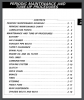
Table of Contents
-
Section 1 Engine
65
-
General Information
16
-
Fuel and Oil Recommendation
19
-
Vehicle Identification Number
19
-
Cylinder Identification
20
-
Maintenance and Lubrication
32
-
Scheduled Maintenance
32
-
Lubrication Points
33
-
Table of Contents
65
-
Precautions
69
-
Precautions for Engine
69
-
-
Engine General Information and Diagnosis
70
-
General Description
70
-
Injection Timing Description
70
-
Self-Diagnosis Function
71
-
-
Schematic and Routing Diagram
73
-
FI System Wiring Diagram
73
-
Terminal Alignment of ECM Coupler
74
-
-
Component Location
75
-
FI System Parts Location
75
-
-
Diagnostic Information and Procedures
76
-
Engine Symptom Diagnosis
76
-
Self-Diagnostic Procedures
80
-
Use of SDS Diagnosis Reset Procedures
82
-
Show Data When Trouble (Displaying Data at the Time of DTC)
83
-
SDS Check
84
-
DTC Table
87
-
Fail-Safe Function Table
89
-
FI System Troubleshooting
90
-
Malfunction Code and Defective Condition Table
91
-
DTC «C12» (P0335): CKP Sensor Circuit Malfunction
94
-
DTC «C13» (P0105-H/L): IAP Sensor (No.1) Circuit Malfunction
97
-
DTC «C14» (P0120-H/L): TP Sensor Circuit Malfunction
106
-
DTC «C15» (P0115-H/L): ECT Sensor Circuit Malfunction
114
-
DTC «C17» (P1750-H/L): IAP Sensor (No.2) Circuit Malfunction
121
-
DTC «C21» (P0110-H/L): IAT Sensor Circuit Malfunction
129
-
DTC «C23» (P1651-H/L): to Sensor Circuit Malfunction
136
-
DTC «C24» (P0351), «C25» (P0352), «C26» (P0353) or «C27» (P0354): Ignition System Malfunction
142
-
DTC «C28» (P1655): Secondary Throttle Valve Actuator (STVA) Malfunction
142
-
DTC «C29» (P1654-H/L): Secondary Throttle Position Sensor (STPS) Circuit Malfunction
146
-
DTC «C31» (P0705): GP Switch Circuit Malfunction
154
-
DTC «C32» (P0201), «C33» (P0202), «C34» (P0203) or «C35» (P0204): Fuel Injector Circuit Malfunction
156
-
DTC «C40» (P0505 / P0506 / P0507): ISC Valve Circuit Malfunction
160
-
DTC «C41» (P0230-H/L): FP Relay Circuit Malfunction
166
-
DTC «C41» (P2505): ECM Power Input Signal Malfunction
169
-
DTC «C42» (P1650): IG Switch Circuit Malfunction
171
-
DTC «C44» (P0130/P0135): HO2 Sensor (HO2S) Circuit Malfunction
171
-
DTC «C49» (P1656): PAIR Control Solenoid Valve Circuit Malfunction
177
-
DTC «C60» (P0480): Cooling Fan Relay Circuit Malfunction
180
-
-
-
Specifications
183
-
Service Data
183
-
-
Special Tools and Equipment
184
-
Special Tool
184
-
-
Emission Control Devices
185
-
Precautions
185
-
Precautions for Emission Control Devices
185
-
-
General Description
185
-
Fuel Injection System Description
185
-
Crankcase Emission Control System Description
186
-
Exhaust Emission Control System Description
187
-
Noise Emission Control System Description
187
-
-
Schematic and Routing Diagram
188
-
PAIR System Hose Routing Diagram
188
-
-
Repair Instructions
189
-
Heated Oxygen Sensor (HO2S) Removal and Installation
189
-
Heated Oxygen Sensor (HO2S) Inspection
189
-
PAIR Reed Valve Removal and Installation
190
-
PAIR Control Solenoid Valve Removal and Installation
190
-
PAIR System Inspection
190
-
Crankcase Breather (PCV) Hose Inspection
192
-
Crankcase Breather (PCV) Hose / Cover / Separator Removal and Installation
192
-
Crankcase Breather (PCV) Cover Inspection
193
-
-
Specifications
194
-
Service Data
194
-
Tightening Torque Specifications
194
-
-
Special Tools and Equipment
194
-
Recommended Service Material
194
-
Special Tool
194
-
-
Engine Electrical Devices
195
-
Precautions
195
-
Precautions for Engine Electrical Device
195
-
-
Component Location
195
-
Engine Electrical Components Location
195
-
-
Diagnostic Information and Procedures
195
-
Engine Symptom Diagnosis
195
-
-
Repair Instructions
195
-
ECM Removal and Installation
195
-
CKP Sensor Inspection
195
-
IAP Sensor (No.1) Removal and Installation
196
-
IAP / TP / IAT Sensor Inspection
196
-
IAP / TP / IAT Sensor Removal and Installation
196
-
ECT Sensor Removal and Installation
196
-
ECT Sensor Inspection
197
-
TO Sensor Removal and Installation
197
-
TO Sensor Inspection
197
-
STP Sensor Inspection
197
-
STP Sensor Adjustment
198
-
STP Sensor Removal and Installation
198
-
STV Actuator Inspection
199
-
STV Actuator Removal and Installation
199
-
ISC Valve Inspection
199
-
ISC Valve Removal and Installation
199
-
ISC Valve Preset and Opening Initialization
200
-
HO2 Sensor Inspection
200
-
HO2 Sensor Removal and Installation
200
-
GP Switch Inspection
200
-
GP Switch Removal and Installation
200
-
-
Specifications
201
-
Service Data
201
-
Tightening Torque Specifications
202
-
-
Special Tools and Equipment
202
-
Recommended Service Material
202
-
Special Tool
202
-
-
Engine Mechanical
203
-
Schematic and Routing Diagram
203
-
Camshaft and Sprocket Assembly Diagram
203
-
Throttle Cable Routing Diagram
204
-
-
Diagnostic Information and Procedures
205
-
Engine Mechanical Symptom Diagnosis
205
-
Compression Pressure Check
205
-
-
Repair Instructions
206
-
Engine Components Removable with the Engine in Place
206
-
Air Cleaner Element Removal and Installation
208
-
Air Cleaner Element Inspection and Cleaning
208
-
Air Cleaner Box Removal and Installation
208
-
Throttle Cable Removal and Installation
208
-
Throttle Cable Inspection
209
-
Throttle Cable Play Inspection and Adjustment
209
-
Throttle Body Components
209
-
Throttle Body Construction
210
-
Throttle Body Removal and Installation
211
-
Throttle Body Disassembly and Assembly
212
-
Throttle Body Inspection and Cleaning
217
-
Throttle Valve Synchronization
217
-
Engine Assembly Removal
219
-
Engine Assembly Installation
223
-
Tightening Torque
224
-
Engine Top Side Disassembly
226
-
Engine Top Side Assembly
230
-
Valve Clearance Inspection and Adjustment
238
-
Camshaft Inspection
238
-
Camshaft Sprocket Inspection
240
-
Camshaft Sprocket Removal and Installation
240
-
Cam Chain Tension Adjuster Inspection
241
-
Cam Chain Guide Removal and Installation
241
-
Cam Chain Guide Inspection
241
-
Cam Chain Tensioner Inspection
242
-
Cylinder Head Disassembly and Assembly
242
-
Cylinder Head Related Parts Inspection
246
-
Valve Guide Replacement
249
-
Valve Seat Repair
250
-
Cylinder Disassembly and Assembly
250
-
Cylinder Inspection
252
-
Piston Ring Removal and Installation
253
-
Piston and Piston Ring Inspection
254
-
Engine Bottom Side Disassembly
255
-
Engine Bottom Side Assembly
263
-
Crank Balancer Disassembly and Assembly
274
-
Crank Balancer Inspection
275
-
Conrod Removal and Installation
276
-
Conrod and Crankshaft Inspection
277
-
Conrod Crank Pin Bearing Inspection and Selection
278
-
Crankshaft Journal Bearing Inspection and Selection
280
-
Crankshaft Thrust Clearance Inspection and Selection
282
-
-
Specifications
285
-
Service Data
285
-
Tightening Torque Specifications
286
-
-
Special Tools and Equipment
287
-
Recommended Service Material
287
-
Special Tool
288
-
-
Engine Lubrication System
291
-
Precautions
291
-
Precautions for Engine Oil
291
-
-
Schematic and Routing Diagram
292
-
Engine Lubrication System Chart Diagram
292
-
Oil Pan
292
-
-
Diagnostic Information and Procedures
293
-
Engine Lubrication Symptom Diagnosis
293
-
Oil Pressure Check
293
-
-
Repair Instructions
294
-
Engine Oil and Filter Replacement
294
-
Engine Oil Level Inspection
294
-
Oil Pan / Oil Strainer / Oil Pressure Regulator Removal and Installation
294
-
Oil Pressure Regulator / Oil Strainer Inspection
296
-
Oil Cooler Removal and Installation
297
-
Oil Pressure Switch Removal and Installation
297
-
Oil Pressure Switch Inspection
298
-
Oil Jet Removal and Installation
298
-
Oil Gallery Jet Removal and Installation
300
-
Oil Jet / Oil Gallery Jet Inspection
300
-
Oil Pump Removal and Installation
301
-
Oil Pump Inspection
303
-
-
Specifications
303
-
Service Data
303
-
Tightening Torque Specifications
303
-
-
Special Tools and Equipment
304
-
Recommended Service Material
304
-
Special Tool
304
-
-
Engine Cooling System
305
-
Precautions
305
-
Precautions for Engine Cooling System
305
-
Precautions for Engine Coolant
305
-
-
General Description
305
-
Engine Coolant Description
305
-
-
Schematic and Routing Diagram
306
-
Cooling Circuit Diagram
306
-
Water Hose Routing Diagram
307
-
-
Diagnostic Information and Procedures
308
-
Engine Cooling Symptom Diagnosis
308
-
-
Repair Instructions
308
-
Cooling Circuit Inspection
308
-
Radiator Cap Inspection
309
-
Radiator Inspection and Cleaning
309
-
Radiator / Cooling Fan Motor Removal and Installation
309
-
Water Hose Inspection
310
-
Water Hose Removal and Installation
311
-
Radiator Reservoir Tank Inspection
311
-
Radiator Reservoir Tank Removal and Installation
312
-
Cooling Fan Inspection
312
-
Cooling Fan Relay Inspection
313
-
ECT Sensor Removal and Installation
313
-
ECT Sensor Inspection
313
-
Thermostat Connector / Thermostat Removal and Installation
313
-
Thermostat Inspection
315
-
Water Pump Components
316
-
Water Pump Construction
316
-
Water Pump Removal and Installation
317
-
Water Pump Disassembly and Assembly
318
-
Water Pump Related Parts Inspection
321
-
-
Specifications
322
-
Service Data
322
-
Tightening Torque Specifications
322
-
-
Special Tools and Equipment
323
-
Recommended Service Material
323
-
Special Tool
323
-
-
Fuel System
324
-
Precautions
324
-
Precautions for Fuel System
324
-
-
General Description
325
-
Fuel System Description
325
-
-
Schematic and Routing Diagram
326
-
Fuel Tank Drain Hose and Breather Hose Routing Diagram
326
-
-
Diagnostic Information and Procedures
327
-
Fuel System Diagnosis
327
-
-
Repair Instructions
328
-
Fuel Pressure Inspection
328
-
Fuel Pump Inspection
328
-
Fuel Discharge Amount Inspection
329
-
Fuel Pump Relay Inspection
330
-
Fuel Hose Inspection
330
-
Fuel Level Gauge Inspection
330
-
Fuel Level Indicator Inspection
330
-
Fuel Level Indicator Switch (Thermistor) Inspection
330
-
Fuel Tank Construction
331
-
Fuel Tank Removal and Installation
332
-
Fuel Pump Components
333
-
Fuel Pump Assembly / Fuel Level Gauge Removal and Installation
334
-
Fuel Pump Disassembly and Assembly
335
-
Fuel Mesh Filter Inspection and Cleaning
337
-
Fuel Injector / Fuel Delivery Pipe / T-Joint Removal and Installation
337
-
Fuel Injector Inspection and Cleaning
337
-
-
Specifications
338
-
Service Data
338
-
Tightening Torque Specifications
338
-
-
Special Tools and Equipment
339
-
Recommended Service Material
339
-
Special Tool
339
-
-
Ignition System
340
-
Schematic and Routing Diagram
340
-
Ignition System Diagram
340
-
Ignition System Components Location
340
-
-
Diagnostic Information and Procedures
341
-
Ignition System Symptom Diagnosis
341
-
No Spark or Poor Spark
342
-
-
Repair Instructions
343
-
Ignition Coil / Plug Cap and Spark Plug Removal and Installation
343
-
Spark Plug Inspection and Cleaning
344
-
Ignition Coil / Plug Cap Inspection
344
-
CKP Sensor Inspection
346
-
CKP Sensor Removal and Installation
347
-
Engine Stop Switch Inspection
347
-
Ignition Switch Inspection
348
-
Ignition Switch Removal and Installation
348
-
-
Specifications
350
-
Service Data
350
-
Tightening Torque Specifications
350
-
-
Special Tools and Equipment
350
-
Special Tool
350
-
-
Starting System
351
-
Schematic and Routing Diagram
351
-
Starting System Diagram
351
-
-
Component Location
351
-
Starting System Components Location
351
-
-
Diagnostic Information and Procedures
351
-
Starting System Symptom Diagnosis
351
-
Starter Motor will Not Run
352
-
Starter Motor Runs but Does Not Crank the Engine
352
-
-
Repair Instructions
353
-
Starter Motor Components
353
-
Starter Motor Removal and Installation
354
-
Starter Motor Disassembly and Assembly
355
-
Starter Motor Inspection
356
-
Starter Relay Removal and Installation
357
-
Starter Relay Inspection
357
-
Turn Signal / Side-Stand Relay Removal and Installation
358
-
Side-Stand / Ignition Interlock System Parts Inspection
358
-
Starter Clutch Removal and Installation
360
-
Starter Clutch Inspection
362
-
Starter Button Inspection
363
-
-
Specifications
363
-
Service Data
363
-
Tightening Torque Specifications
363
-
-
Special Tools and Equipment
364
-
Recommended Service Material
364
-
Special Tool
364
-
-
Charging System
365
-
Schematic and Routing Diagram
365
-
Charging System Diagram
365
-
-
Component Location
365
-
Charging System Components Location
365
-
-
Diagnostic Information and Procedures
365
-
Charging System Symptom Diagnosis
365
-
Battery Runs down Quickly
366
-
-
Repair Instructions
367
-
Battery Current Leakage Inspection
367
-
Regulated Voltage Inspection
367
-
Generator Inspection
367
-
Generator Removal and Installation
368
-
Regulator / Rectifier Construction
372
-
Regulator / Rectifier Inspection
372
-
Battery Components
373
-
Battery Charging
373
-
Battery Removal and Installation
376
-
Battery Visual Inspection
376
-
-
Specifications
377
-
Service Data
377
-
Tightening Torque Specifications
377
-
-
Special Tools and Equipment
378
-
Recommended Service Material
378
-
Special Tool
378
-
-
Exhaust System
379
-
Precautions
379
-
Precautions for Exhaust System
379
-
-
Repair Instructions
380
-
Exhaust System Construction
380
-
Exhaust Pipe / Muffler Removal and Installation
381
-
Exhaust System Inspection
384
-
-
Specifications
384
-
Tightening Torque Specifications
384
-
-
Special Tools and Equipment
384
-
Recommended Service Material
384
-
-
-
Section 2 Suspension
385
-
Precautions
386
-
Precautions for Suspension
386
-
-
Suspension General Diagnosis
387
-
Diagnostic Information and Procedures
387
-
Suspension and Wheel Symptom Diagnosis
387
-
-
Repair Instructions
388
-
Front Fork Components
388
-
Front Fork Removal and Installation
389
-
Front Fork Inspection
390
-
Front Fork Adjustment
391
-
Front Fork Disassembly and Assembly
391
-
Front Fork Parts Inspection
396
-
-
Front Suspension
388
-
Specifications
397
-
Service Data
397
-
Tightening Torque Specifications
397
-
-
Special Tools and Equipment
398
-
Recommended Service Material
398
-
Special Tool
398
-
-
Rear Suspension
399
-
Repair Instructions
399
-
Rear Suspension Components
399
-
Rear Suspension Assembly Construction
400
-
Rear Shock Absorber Removal and Installation
401
-
Rear Suspension Inspection
401
-
Rear Shock Absorber Inspection
402
-
Rear Suspension Adjustment
402
-
Rear Shock Absorber Disposal
402
-
Cushion Lever Removal and Installation
403
-
Cushion Lever Inspection
404
-
Cushion Lever Bearing Removal and Installation
404
-
Swingarm / Cushion Rod Removal and Installation
405
-
Swingarm Related Parts Inspection
407
-
Swingarm Bearing Removal and Installation
408
-
-
Specifications
410
-
Service Data
410
-
Tightening Torque Specifications
410
-
-
Special Tools and Equipment
411
-
Recommended Service Material
411
-
Special Tool
411
-
-
Wheels and Tires
412
-
Precautions
412
-
Precautions for Wheel and Tire
412
-
-
Repair Instructions
413
-
Front Wheel Components
413
-
Front Wheel Assembly Construction
415
-
Front Wheel Assembly Removal and Installation
417
-
Front Wheel Related Parts Inspection
419
-
Front Wheel Dust Seal / Bearing Removal and Installation
420
-
Rear Wheel Components
423
-
Rear Wheel Assembly Construction
425
-
Rear Wheel Assembly Removal and Installation
427
-
Rear Wheel Related Parts Inspection
428
-
Rear Wheel Dust Seal / Bearing Removal and Installation
429
-
Tire Removal and Installation
431
-
Wheel / Tire / Air Valve Inspection and Cleaning
432
-
Air Valve Removal and Installation
433
-
Wheel Balance Check and Adjustment
434
-
-
Specifications
434
-
Service Data
434
-
Tightening Torque Specifications
435
-
-
Special Tools and Equipment
435
-
Recommended Service Material
435
-
Special Tool
435
-
-
-
Section 3 Driveline / Axle
437
-
Precautions
438
-
Precautions for Driveline / Axle
438
-
-
Diagnostic Information and Procedures
439
-
Drive Chain and Sprocket Symptom Diagnosis
439
-
-
Repair Instructions
439
-
Drive Chain Related Components
439
-
Engine Sprocket Removal and Installation
440
-
Rear Sprocket / Rear Sprocket Mounting Drum Removal and Installation
442
-
Drive Chain Related Parts Inspection
443
-
Sprocket Mounting Drum Dust Seal / Bearing Removal and Installation
444
-
Drive Chain Replacement
445
-
-
Drive Chain / Drive Train / Drive Shaft
439
-
Specifications
448
-
Service Data
448
-
Tightening Torque Specifications
448
-
-
Special Tools and Equipment
449
-
Recommended Service Material
449
-
Special Tool
449
-
-
-
Section 4 Brake
451
-
Precautions
453
-
Precautions for Brake System
453
-
Brake Fluid Information
453
-
-
Brake Control System and Diagnosis
454
-
Schematic and Routing Diagram
454
-
Front Brake Hose Routing Diagram
454
-
Rear Brake Hose Routing Diagram
458
-
-
Repair Instructions
460
-
Brake Pedal Height Inspection and Adjustment
460
-
Front Brake Light Switch Inspection
460
-
Rear Brake Light Switch Inspection
461
-
Rear Brake Light Switch Inspection and Adjustment
461
-
Brake Fluid Level Check
461
-
Brake Hose Inspection
461
-
Air Bleeding from Brake Fluid Circuit
461
-
Brake Fluid Replacement
463
-
Front Brake Hose Removal and Installation
465
-
Rear Brake Hose Removal and Installation
466
-
Front Brake Master Cylinder Components
467
-
Front Brake Master Cylinder Assembly Removal and Installation
467
-
Front Brake Master Cylinder / Brake Lever Disassembly and Assembly
468
-
Front Brake Master Cylinder Parts Inspection
470
-
Rear Brake Master Cylinder Components
471
-
Rear Brake Master Cylinder Assembly Removal and Installation
471
-
Rear Brake Master Cylinder Disassembly and Assembly
472
-
Rear Brake Master Cylinder Parts Inspection
473
-
-
Diagnostic Information and Procedures
460
-
Brake Symptom Diagnosis
460
-
-
Specifications
474
-
Service Data
474
-
Tightening Torque Specifications
474
-
-
Special Tools and Equipment
475
-
Recommended Service Material
475
-
Special Tool
475
-
-
Front Brakes
476
-
Repair Instructions
476
-
Front Brake Components
476
-
Front Brake Pad Inspection
477
-
Front Brake Pad Replacement
477
-
Front Brake Caliper Removal and Installation
478
-
Front Brake Caliper Disassembly and Assembly
479
-
Front Brake Caliper Parts Inspection
481
-
Front Brake Disc Removal and Installation
482
-
Front Brake Disc Inspection
482
-
-
Specifications
483
-
Service Data
483
-
Tightening Torque Specifications
483
-
-
Special Tools and Equipment
484
-
Recommended Service Material
484
-
Special Tool
484
-
-
Repair Instructions
485
-
Rear Brake Components
485
-
Rear Brake Pad Inspection
486
-
Rear Brake Pad Replacement
486
-
Rear Brake Caliper Removal and Installation
488
-
Rear Brake Caliper Disassembly and Assembly
488
-
Rear Brake Caliper Parts Inspection
490
-
Rear Brake Disc Removal and Installation
491
-
Rear Brake Disc Inspection
491
-
-
Rear Brakes
485
-
Specifications
492
-
Service Data
492
-
Tightening Torque Specifications
492
-
-
Special Tools and Equipment
493
-
Recommended Service Material
493
-
Special Tool
493
-
-
Precautions
494
-
Precautions for ABS
494
-
ABS Information
494
-
-
General Description
494
-
Wheel Speed Sensor Description
494
-
ABS Control Unit Description
495
-
Hydraulic Unit (HU) Description
497
-
Self-Diagnosis Function and ABS Indicator Light Description
498
-
Fail-Safe Function Description
499
-
-
Abs
494
-
Schematic and Routing Diagram
500
-
ABS Wiring Diagram
500
-
ABS Unit Diagram
501
-
Front Wheel Speed Sensor Routing Diagram
502
-
Rear Wheel Speed Sensor Routing Diagram
504
-
-
Component Location
505
-
ABS Components Location
505
-
-
Diagnostic Information and Procedures
506
-
ABS Troubleshooting
506
-
Pre-Diagnosis Inspection
508
-
ABS Indicator Light Inspection
510
-
DTC (Diagnostic Trouble Code) Output
516
-
DTC (Diagnostic Trouble Code) Deleting
518
-
SDS Check
522
-
Active Control Inspection
523
-
DTC Table
527
-
DTC «13» (C1613): Wheel Speed Sensor Rotor Malfunction
528
-
DTC «14» (C1614): Wheel Speed Sensor Rotor Malfunction
530
-
DTC «22» (C1622): ABS Actuator Circuit Malfunction
532
-
DTC «23» (C1623): ABS Actuator Circuit Malfunction
534
-
DTC «25» (C1625): Wheel Speed Sensor Related Malfunction
536
-
DTC «35» (C1635): ABS Motor Malfunction
538
-
DTC «41» (C1641): Wheel Speed Sensor Signal Malfunction
540
-
DTC «42» (C1642): Wheel Speed Sensor Circuit Open
542
-
DTC «43» (C1643): Wheel Speed Sensor Circuit Short
546
-
DTC «44» (C1644): Wheel Speed Sensor Signal Malfunction
548
-
DTC «45» (C1645): Wheel Speed Sensor Circuit Open
550
-
DTC «46» (C1646): Wheel Speed Sensor Circuit Short
554
-
DTC «47» (C1647): Supply Voltage (Increased)
556
-
DTC «48» (C1648): Supply Voltage (Decreased)
558
-
DTC «55» (C1655): ABS Control Unit Malfunction
560
-
DTC «61» (C1661): ABS Solenoid Malfunction
562
-
-
-
Repair Instructions
563
-
ABS Control Unit Coupler Disconnect and Connect
563
-
Front Wheel Speed Sensor Removal and Installation
564
-
Rear Wheel Speed Sensor Removal and Installation
564
-
Front Wheel Speed Sensor Rotor Removal and Installation
565
-
Rear Wheel Speed Sensor Rotor Removal and Installation
566
-
Wheel Speed Sensor and Sensor Rotor Inspection
567
-
ABS Control Unit/Hu Removal and Installation
567
-
-
Specifications
569
-
Tightening Torque Specifications
569
-
-
Special Tools and Equipment
569
-
Special Tool
569
-
-
-
Section 5 Transmission / Transaxle
571
-
Precautions
572
-
Precautions for Transmission / Transaxle
572
-
-
Diagnostic Information and Procedures
573
-
Manual Transmission Symptom Diagnosis
573
-
-
Manual Transmission
573
-
Repair Instructions
574
-
Transmission Components
574
-
Transmission Removal
575
-
Transmission Installation
577
-
Transmission Construction
580
-
Countershaft Gear / Driveshaft Gear Disassembly and Assembly
581
-
Transmission Related Parts Inspection
584
-
Gear Position (GP) Switch Inspection
584
-
Gear Position (GP) Switch Removal and Installation
584
-
Gearshift Lever Construction
585
-
Gearshift Lever Removal and Installation
586
-
Gearshift Lever Height Inspection and Adjustment
586
-
Gearshift Shaft / Gearshift Cam Plate Components
586
-
Gearshift Construction
587
-
Gearshift Shaft / Gearshift Cam Plate Removal and Installation
587
-
Gearshift Linkage Inspection
590
-
Gearshift Shaft Oil Seal / Bearing Removal and Installation
591
-
-
Specifications
592
-
Service Data
592
-
Tightening Torque Specifications
592
-
-
Special Tools and Equipment
593
-
Recommended Service Material
593
-
Special Tool
593
-
-
Precautions
594
-
Precautions for Clutch System
594
-
Clutch Fluid (Brake Fluid) Information
594
-
-
Clutch
594
-
Schematic and Routing Diagram
595
-
Clutch Hose Routing Diagram
595
-
-
Repair Instructions
596
-
Clutch Lever Position Switch Inspection
596
-
Clutch Fluid Level Check
596
-
Clutch Hose Inspection
596
-
Air Bleeding from Clutch Fluid Circuit
597
-
Clutch Fluid Replacement
597
-
Clutch Hose Removal and Installation
598
-
Clutch Control System Components
599
-
Clutch Master Cylinder Assembly Removal and Installation
600
-
Clutch Master Cylinder / Clutch Lever Disassembly and Assembly
601
-
Clutch Master Cylinder Parts Inspection
603
-
Clutch Release Cylinder / Push Rod Removal and Installation
603
-
Clutch Push Rod (Left) Inspection
604
-
Clutch Release Cylinder Disassembly and Assembly
604
-
Clutch Release Cylinder Inspection
604
-
Clutch Components
605
-
Clutch Removal
606
-
Clutch Installation
607
-
Clutch Parts Inspection
611
-
-
Diagnostic Information and Procedures
596
-
Clutch System Symptom Diagnosis
596
-
-
Specifications
612
-
Service Data
612
-
Tightening Torque Specifications
612
-
-
Special Tools and Equipment
613
-
Recommended Service Material
613
-
Special Tool
613
-
-
-
Section 6 Steering
615
-
Precautions
616
-
Precautions for Steering
616
-
-
Steering General Diagnosis
617
-
Diagnostic Information and Procedures
617
-
Steering Symptom Diagnosis
617
-
-
Repair Instructions
618
-
Handlebar Components
618
-
Handlebar Construction
619
-
Handlebar Removal and Installation
620
-
Handlebars Inspection
621
-
Steering Components
622
-
Steering Removal and Installation
623
-
Steering Related Parts Inspection
626
-
Steering System Inspection
626
-
Steering Stem Bearing Removal and Installation
626
-
Steering Tension Adjustment
627
-
-
Steering / Handlebar
618
-
Specifications
628
-
Tightening Torque Specifications
628
-
-
Special Tools and Equipment
629
-
Recommended Service Material
629
-
Special Tool
629
-
-
-
Section 9 Body and Accessories
631
-
Precautions
633
-
Precautions for Electrical System
633
-
-
Component Location
633
-
Electrical Components Location
633
-
-
Schematic and Routing Diagram
634
-
Wiring Diagram (GSF1250)
634
-
Wiring Diagram (GSF1250S)
636
-
Wiring Diagram (GSF1250A)
638
-
Wiring Diagram (GSF1250SA)
639
-
Wiring Harness Routing Diagram
641
-
-
Wiring Systems
634
-
Specifications
644
-
Service Data
644
-
Tightening Torque Specifications
644
-
-
Repair Instructions
645
-
Headlight Components
645
-
Headlight Removal and Installation
646
-
Headlight Bulb Replacement
647
-
Headlight Beam Adjustment
649
-
Rear Combination Light Components
649
-
Rear Combination Light Construction
650
-
Rear Combination Light Removal and Installation
650
-
Brake Light Bulb / Taillight Bulb Replacement
651
-
License Plate Light Components
651
-
License Plate Light Removal and Installation
652
-
License Plate Light Bulb Replacement
652
-
Turn Signal Light Components
653
-
Front Turn Signal Light Removal and Installation
653
-
Rear Turn Signal Light Removal and Installation
654
-
Turn Signal Light Bulb Replacement
654
-
Reflex Refractor Construction
654
-
Turn Signal / Side-Stand Relay Inspection
655
-
Turn Signal / Side-Stand Relay Removal and Installation
655
-
Hazard Switch Inspection
655
-
Turn Signal Switch Inspection
655
-
Passing Light Switch Inspection
656
-
Dimmer Switch Inspection
656
-
-
Lighting Systems
645
-
Special Tools and Equipment
657
-
Special Tool
657
-
-
Specifications
657
-
Service Data
657
-
Tightening Torque Specifications
657
-
-
Combination Meter / Fuel Meter / Horn
658
-
General Description
658
-
Combination Meter System Description
658
-
-
Repair Instructions
659
-
Combination Meter Components
659
-
Combination Meter Removal and Installation
661
-
Combination Meter Disassembly and Assembly
661
-
Combination Meter Inspection
662
-
Engine Coolant Temperature Indicator Light Inspection
662
-
Engine Coolant Temperature Removal and Installation
663
-
Fuel Level Indicator Inspection
663
-
Fuel Level Indicator Switch (Thermistor) Inspection
664
-
Fuel Level Gauge Inspection
665
-
Speedometer Inspection
665
-
Speed Sensor Removal and Installation
665
-
Speed Sensor Inspection
666
-
Oil Pressure Indicator Inspection
666
-
Oil Pressure Switch Removal and Installation
667
-
Ignition Switch Inspection
667
-
Ignition Switch Removal and Installation
667
-
Horn Inspection
667
-
Horn Removal and Installation
668
-
-
Special Tools and Equipment
669
-
Special Tool
669
-
-
Specifications
669
-
Service Data
669
-
Tightening Torque Specifications
669
-
-
Exterior Parts
670
-
Schematic and Routing Diagram
670
-
Seat Lock Cable Routing Diagram
670
-
-
Repair Instructions
671
-
Exterior Parts Construction
671
-
Front Fender Construction
673
-
Frame Cover Cushion Construction
673
-
Engine Sprocket Outer Cover Cushion Construction
674
-
Fastener Removal and Installation
674
-
Exterior Parts Removal and Installation
675
-
Seat Height Adjustment
678
-
-
Body Structure
679
-
Repair Instructions
679
-
Body Frame Construction
679
-
Engine Mounting Bracket Bushing Replacement
679
-
Engine Mount Bushing Replacement
680
-
Front Footrest Bracket Construction
680
-
Side-Stand Construction
681
-
Side-Stand Removal and Installation
682
-
Center Stand Construction
682
-
Center Stand Removal and Installation
682
-
-
-
Specifications
683
-
Tightening Torque Specifications
683
-
-
Special Tools and Equipment
683
-
Recommended Service Material
683
-
-
Advertisement

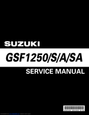
Suzuki GSF1250 Owner’s Manual (60 pages)
Brand: Suzuki
|
Category: Motorcycle
|
Size: 36.41 MB
Table of Contents
-
Break-In (Running-In)
2
-
Table of Contents
3
-
Table of Contents
4
-
Consumer Information
4
-
Accessory Information and Precaution Safety Tips
5
-
Modification
6
-
Safe Riding Recommendation for Motorcycle Riders
6
-
Serial Number Location
6
-
Noise Control System (Australia Only)
7
-
Location of Parts
8
-
Vehicle View and Parts Identification
8
-
Ignition Switch
9
-
Instrument Panel
10
-
Fuel Meter
11
-
Odometer
11
-
Tachometer
11
-
Trip Meters
11
-
Clock
12
-
Fuel Injection System Indicator «FI»
12
-
Coolant Temperature Indicator Light
13
-
High Beam Indicator Light
13
-
Oil Pressure Indicator Light
13
-
Turn Signal Indicator Light
13
-
Clutch Lever Adjustment
14
-
Hazard Warning Switch
14
-
Left Handlebar
14
-
Turn Signal Light Switch
14
-
Electric Starter Button
15
-
Engine Stop Switch
15
-
-
Right Handlebar
15
-
Throttle Grip
15
-
Fuel Tank Cap
16
-
Gearshift Lever
16
-
Rear Brake Pedal
16
-
Seat Lock and Helmet Holders
17
-
Stands
17
-
Damping Force Adjustment
18
-
Spring Pre-Load Adjustment
18
-
-
Suspension Adjustment
18
-
Fuel, Engine Oil and Coolant Recommendations
19
-
Seat Height Adjustment
19
-
Fuel Octane Rating
20
-
Oxygenated Fuel Recommendation
20
-
Engine Oil
20
-
SAE Engine Oil Viscosity
20
-
Coolant
21
-
Anti-Freeze
21
-
Required Amount of Water/Coolant
21
-
Jaso T903
21
-
Break-In (Running-In) and Inspection before Riding
22
-
Maximum Engine Speed Recommendation
23
-
Breaking in the New Tires
23
-
Initial Service
23
-
Riding Tips
24
-
Starting the Engine
25
-
Starting off
25
-
Using the Transmission
26
-
Riding on Hills
26
-
Stopping and Parking
26
-
Shifting Up/Down Schedule
26
-
Inspection and Maintenance
27
-
Maintenance Schedule
28
-
Tool Kit Location
29
-
Fuel Tank Removal
29
-
Lubrication Points
30
-
Battery
31
-
Air Cleaner
31
-
Air Cleaner Drain Tube
32
-
Spark Plugs Removal
33
-
Spark Plug Inspection
33
-
Spark Plug Replacement Guide
33
-
Engine Oil Level Check
34
-
Fuel Hose
34
-
Spark Plug Installation
34
-
Engine Oil and Filter Change
35
-
Engine Idle Speed Inspection
36
-
Throttle Cable Adjustment
37
-
Clutch
37
-
Coolant Level
38
-
Coolant Change
38
-
Drive Chain
38
-
Drive Chain Cleaning and Oiling
39
-
Drive Chain Adjustment
39
-
Brakes
40
-
Brake Fluid
40
-
Brake Pads
40
-
Tires
41
-
Rear Brake Light Switch
41
-
Rear Brake Pedal Adjustment
41
-
Tire Pressure and Loading
42
-
Tire Condition and Type
42
-
Cold Tire Inflation Pressure
42
-
Side Stand/Ignition Interlock Switch
43
-
Front Wheel Removal
44
-
Rear Wheel Removal
45
-
Light Bulb Replacement
46
-
Headlight/Position Light
46
-
Brake Light/Taillight
47
-
Headlight Beam Adjustment
48
-
License Plate Light
48
-
Turn Signal Light
48
-
Fuses
49
-
Troubleshooting
50
-
Fuel Supply Check
51
-
Ignition System Check
51
-
Engine Stalling
51
-
Cleaning
53
-
Washing the Motorcycle
53
-
Waxing the Motorcycle
53
-
Inspection after Cleaning
53
-
Storage
54
-
Procedure for Returning to Service
54
-
Specifications
55
-
Index
56
-
Advertisement
Related Products
-
Suzuki GSF1250A
-
Suzuki GSF1250S
-
Suzuki GSF1250SA
-
Suzuki GSF1200 2001
-
Suzuki GSF1200S 2001
-
Suzuki bandit gsf 1200v 1997
-
Suzuki bandit gsf 1200sv 1997
-
Suzuki GSF1200
-
Suzuki GSF1200S
-
Suzuki GSF1200SK6
Suzuki Categories
Motorcycle
Automobile
Musical Instrument
Offroad Vehicle
Outboard Motor
More Suzuki Manuals
Log in / Register
-
- Search titles only
- Posted by Member:
-
Separate names with a comma.
- Newer Than:
-
-
Search this category only
- Search only resource descriptions
-
Search this category only
-
Useful Searches
- Recent Posts
More…

-
This site uses cookies. By continuing to use this site, you are agreeing to our use of cookies. Learn More.
-
For access to these resources PREMIUM membership is required …
Please follow this LINK
Cookies
Resources
-
Download Not Available
4.2 MB .pdf
![]()
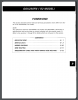
WORKSHOP MANUAL Suzuki GSF250 Bandit GJ74a — part 1 2022-08-01
cover-introduction in Japanese
- Overview
- Version History
-

Cover-introduction in Japanese

- Log in with Facebook
- Your name or email address:
- Do you already have an account?
-
- No, create an account now.
- Yes, my password is:
-
Forgot your password?
-
Stay logged in
- Close Menu
-
Home
- Recent Posts
- Recent Activity
- Authors
-
Forums
- Search Forums
- Recent Posts
-
The Garage
- Search Showcase
- Most Active Members
- New Items
-
Resources
- Search Resources
- Most Active Authors
- Latest Reviews
-
Members
- Notable Members
- Registered Members
- Current Visitors
- Recent Activity
- New Profile Posts
- Search