- Manuals
- Brands
- SUZUKI Manuals
- Motorcycle
- GSX-R600
Manuals and User Guides for SUZUKI GSX-R600. We have 3 SUZUKI GSX-R600 manuals available for free PDF download: Manual, Service Manual

suzuki GSX-R600 Manual (653 pages)
Brand: suzuki
|
Category: Motorcycle
|
Size: 21.59 MB
Table of Contents
-
Section 1 Engine
63
-
General Information
13
-
Cylinder Identification
17
-
Maintenance and Lubrication
28
-
Scheduled Maintenance
28
-
Lubrication Points
29
-
Front Fork Inspection
47
-
Table of Contents
63
-
Precautions
68
-
Precautions for Engine
68
-
-
Engine General Information and Diagnosis
69
-
General Description
69
-
Injection Timing Description
69
-
Self-Diagnosis Function
71
-
-
Schematic and Routing Diagram
72
-
FI System Wiring Diagram
72
-
Terminal Alignment of ECM Coupler
74
-
-
Component Location
75
-
FI System Parts Location
75
-
-
Diagnostic Information and Procedures
77
-
Engine Symptom Diagnosis
77
-
Self-Diagnostic Procedures
81
-
Use of SDS Diagnosis Reset Procedures
83
-
Show Data When Trouble (Displaying Data at the Time of DTC)
84
-
SDS Check
85
-
DTC Table
89
-
Fail-Safe Function Table
91
-
FI System Troubleshooting
92
-
Malfunction Code and Defective Condition Table
94
-
DTC «C11» (P0340): CMP Sensor Circuit Malfunction
98
-
DTC «C12» (P0335): CKP Sensor Circuit Malfunction
101
-
DTC «C13» (P0105-H/L): IAP Sensor Circuit Malfunction
104
-
DTC «C14» (P0120-H/L): TP Sensor Circuit Malfunction
113
-
DTC «C15» (P0115-H/L): ECT Sensor Circuit Malfunction
120
-
DTC «C21» (P0110-H/L): IAT Sensor Circuit Malfunction
125
-
DTC «C22» (P1450-H/L): AP Sensor Circuit Malfunction
130
-
DTC «C23» (P1651-H/L): to Sensor Circuit Malfunction
139
-
-
DTC «C24» (P0351), «C25» (P0352), «C26» (P0353) or «C27» (P0354): Ignition System Malfunction
146
-
DTC «C28» (P1655): Secondary Throttle Valve Actuator (STVA) Malfunction
146
-
DTC «C29» (P1654-H/L): Secondary Throttle Position Sensor (STPS) Circuit Malfunction
150
-
DTC «C31» (P0705): GP Switch Circuit Malfunction
157
-
DTC «C32» (P0201), «C33» (P0202), «C34» (P0203) or «C35» (P0204): Primary Fuel Injector Circuit Malfunction
159
-
DTC «C36» (P1764), «C37» (P1765), «C38» (P1766) or «C39» (P1767): Secondary Fuel Injector Circuit Malfunction
162
-
DTC «C40» (P0505 / P0506 / P0507): ISC Valve Circuit Malfunction
165
-
DTC «C41» (P0230-H/L): FP Relay Circuit Malfunction
169
-
DTC «C41» (P2505): ECM Power Input Signal Malfunction
172
-
DTC «C42» (P1650): IG Switch Circuit Malfunction
174
-
DTC «C44» (P0130/P0135): HO2 Sensor (HO2S) Circuit Malfunction
174
-
DTC «C46» (P1657-H/L or P1658): EXCV Actuator Circuit Malfunction
180
-
DTC «C49» (P1656): PAIR Control Solenoid Valve Circuit Malfunction
194
-
DTC «C60» (P0480): Cooling Fan Relay Circuit Malfunction
197
-
DTC «C62» (P0443): EVAP System Purge Control Solenoid Valve Circuit Malfunction (E-33 Only)
200
-
DTC «C91» (P0500): Vehicle Speed Sensor Circuit Malfunction
203
-
DTC «C93» (P1769): Steering Damper Solenoid Valve Circuit Malfunction
206
-
-
Specifications
210
-
Service Data
210
-
-
Special Tools and Equipment
211
-
Special Tool
211
-
-
Emission Control Devices
213
-
Precautions
213
-
Precautions for Emission Control Devices
213
-
-
General Description
213
-
Fuel Injection System Description
213
-
Crankcase Emission Control System Description
214
-
Exhaust Emission Control System Description
215
-
Noise Emission Control System Description
216
-
Evaporative Emission Control System Diagram (Only for
216
-
-
Schematic and Routing Diagram
217
-
PAIR System Hose Routing Diagram
217
-
EVAP Canister Hose Routing Diagram
218
-
-
Repair Instructions
219
-
Heated Oxygen Sensor (HO2S) Removal and Installation
219
-
Heated Oxygen Sensor (HO2S) Inspection
219
-
PAIR Reed Valve Removal and Installation
219
-
PAIR Control Solenoid Valve Removal and Installation
221
-
PAIR System Inspection
221
-
Crankcase Breather (PCV) Hose Inspection
222
-
Crankcase Breather (PCV) Hose / Reed Valve / Cover Removal and Installation
223
-
Crankcase Breather (PCV) Cover Inspection
224
-
Crankcase Breather (PCV) Reed Valve Inspection
224
-
Evaporative Emission Control System Removal and Installation (Only for
224
-
Evaporative Emission Control System
224
-
Inspection (Only for
224
-
-
Specifications
229
-
Service Data
229
-
Tightening Torque Specifications
229
-
-
Special Tools and Equipment
229
-
Special Tool
229
-
-
Engine Electrical Devices
230
-
Precautions
230
-
Precautions for Engine Electrical Device
230
-
-
Component Location
230
-
Engine Electrical Components Location
230
-
-
Diagnostic Information and Procedures
230
-
Engine Symptom Diagnosis
230
-
-
Repair Instructions
230
-
ECM Removal and Installation
230
-
CMP Sensor Inspection
231
-
CMP Sensor Removal and Installation
231
-
CKP Sensor Inspection
232
-
CKP Sensor Removal and Installation
232
-
IAP Sensor Inspection
232
-
IAP Sensor Removal and Installation
232
-
TP Sensor Inspection
232
-
TP Sensor Removal and Installation
232
-
TP Sensor Adjustment
233
-
ECT Sensor Removal and Installation
233
-
ECT Sensor Inspection
234
-
IAT Sensor Removal and Installation
234
-
IAT Sensor Inspection
235
-
AP Sensor Inspection
235
-
AP Sensor Removal and Installation
235
-
TO Sensor Inspection
235
-
TO Sensor Removal and Installation
235
-
STP Sensor Inspection
236
-
STP Sensor Adjustment
236
-
STP Sensor Removal and Installation
237
-
STV Actuator Inspection
237
-
STV Actuator Removal and Installation
237
-
ISC Valve Inspection
237
-
ISC Valve Removal and Installation
237
-
ISC Valve Preset and Opening Initialization
238
-
HO2 Sensor Inspection
238
-
HO2 Sensor Removal and Installation
238
-
GP Switch Inspection
238
-
GP Switch Removal and Installation
238
-
-
Specifications
239
-
Service Data
239
-
Tightening Torque Specifications
239
-
-
Special Tools and Equipment
240
-
Special Tool
240
-
-
Engine Mechanical
241
-
Schematic and Routing Diagram
241
-
Camshaft and Sprocket Assembly Diagram
241
-
Throttle Cable Routing Diagram
242
-
-
Diagnostic Information and Procedures
243
-
Engine Mechanical Symptom Diagnosis
243
-
Compression Pressure Check
243
-
-
Repair Instructions
244
-
Engine Components Removable with the Engine in Place
244
-
Air Cleaner Element Removal and Installation
246
-
Air Cleaner Box Removal and Installation
247
-
Air Cleaner Element Inspection and Cleaning
247
-
Throttle Cable Removal and Installation
247
-
Throttle Cable Inspection
247
-
Throttle Cable Play Inspection and Adjustment
247
-
Throttle Body Components
248
-
Throttle Body Construction
249
-
Throttle Body Removal and Installation
250
-
Throttle Body Disassembly and Assembly
251
-
Throttle Body Inspection and Cleaning
255
-
ISC Valve Visual Inspection
256
-
Throttle Valve Synchronization
256
-
ISC Valve Reset
258
-
TP Reset
258
-
Engine Assembly Removal
259
-
Engine Assembly Installation
263
-
Engine Top Side Disassembly
265
-
Engine Top Side Assembly
267
-
Camshaft Inspection
274
-
Camshaft Sprocket
276
-
Cam Chain Tension Adjuster Inspection
276
-
Cam Chain Guide / Cam Chain Tensioner Removal and Installation
277
-
Cam Chain Guide Inspection
277
-
Cam Chain Tensioner Inspection
277
-
Cylinder Head Disassembly and Assembly
278
-
Cylinder Head Related Parts Inspection
282
-
Valve Guide Replacement
285
-
Valve Seat Repair
287
-
Engine Bottom Side Disassembly
287
-
Engine Bottom Side Assembly
294
-
Cylinder Inspection
309
-
Piston Ring Removal and Installation
309
-
Piston and Piston Ring Inspection
311
-
Conrod Crank Pin Bearing Removal and Installation
313
-
Conrod and Crankshaft Inspection
313
-
Conrod Crank Pin Bearing Inspection and Selection
314
-
Crankshaft Journal Bearing Inspection and Selection
316
-
Crankshaft Thrust Clearance Inspection and Selection
319
-
-
Specifications
321
-
Service Data
321
-
Tightening Torque Specifications
323
-
-
Special Tools and Equipment
324
-
Recommended Service Material
324
-
Special Tool
324
-
-
Engine Lubrication System
327
-
Precautions
327
-
Precautions for Engine Oil
327
-
-
Schematic and Routing Diagram
328
-
Engine Lubrication System Chart Diagram
328
-
Oil Pan
328
-
Engine Lubrication Circuit Diagram
329
-
-
Diagnostic Information and Procedures
331
-
Engine Lubrication Symptom Diagnosis
331
-
Oil Pressure Check
331
-
-
Repair Instructions
332
-
Engine Oil and Filter Replacement
332
-
Engine Oil Level Inspection
332
-
Oil Pan / Oil Strainer / Oil Pressure Regulator
332
-
Removal and Installation
332
-
-
Oil Pressure Regulator / Oil Strainer Inspection
333
-
Oil Cooler / Oil Cooler Hose Inspection
334
-
Oil Cooler Removal and Installation
334
-
Oil Pressure Switch Removal and Installation
335
-
Oil Pressure Switch Inspection
335
-
Oil Jet / Oil Gallery Jet Removal and Installation
335
-
Oil Jet / Oil Gallery Jet Inspection
337
-
Oil Pump Removal and Installation
338
-
Oil Pump Inspection
339
-
Oil Pump Drive Gear Removal and Installation
339
-
-
Specifications
340
-
Service Data
340
-
Tightening Torque Specifications
341
-
-
Special Tools and Equipment
341
-
Recommended Service Material
341
-
Special Tool
341
-
-
Engine Cooling System
342
-
Precautions
342
-
Precautions for Engine Cooling System
342
-
Precautions for Engine Coolant
342
-
-
General Description
342
-
Engine Coolant Description
342
-
-
Schematic and Routing Diagram
343
-
Cooling Circuit Diagram
343
-
Water Hose Routing Diagram
344
-
-
Diagnostic Information and Procedures
345
-
Engine Cooling Symptom Diagnosis
345
-
-
Repair Instructions
345
-
Cooling Circuit Inspection
345
-
Radiator Cap Inspection
346
-
Radiator Inspection and Cleaning
346
-
Radiator / Cooling Fan Motor Removal and Installation
346
-
Water Hose Inspection
347
-
Water Hose Removal and Installation
348
-
Radiator Reservoir Tank Inspection
348
-
Radiator Reservoir Tank Removal and Installation
349
-
Cooling Fan Inspection
349
-
Cooling Fan Relay Inspection
349
-
ECT Sensor Removal and Installation
350
-
ECT Sensor Inspection
350
-
Thermostat Removal and Installation
350
-
Thermostat Inspection
351
-
Water Pump Components
352
-
Water Pump Construction
353
-
Water Pump Removal and Installation
353
-
Water Pump Disassembly and Assembly
354
-
Water Pump Related Parts Inspection
357
-
-
Specifications
359
-
Service Data
359
-
Tightening Torque Specifications
359
-
-
Special Tools and Equipment
360
-
Recommended Service Material
360
-
Special Tool
360
-
-
Fuel System
361
-
Precautions
361
-
Precautions for Fuel System
361
-
-
General Description
362
-
Fuel Injection System Description
362
-
-
Schematic and Routing Diagram
363
-
Fuel Tank Drain Hose and Breather Hose Routing Diagram
363
-
-
Diagnostic Information and Procedures
364
-
Fuel System Diagnosis
364
-
-
Repair Instructions
365
-
Fuel Pressure Inspection
365
-
Fuel Pump Inspection
365
-
Fuel Discharge Amount Inspection
366
-
Fuel Pump Relay Inspection
367
-
Fuel Hose Inspection
367
-
Fuel Level Gauge Inspection
367
-
Fuel Tank Construction
368
-
Fuel Tank Removal and Installation
369
-
Fuel Pump Components
370
-
Fuel Pump Disassembly and Assembly
371
-
Fuel Mesh Filter Inspection and Cleaning
373
-
Fuel Injector / Fuel Delivery Pipe / T-Joint Removal and Installation
373
-
Fuel Injector Inspection and Cleaning
373
-
-
Specifications
374
-
Special Tools and Equipment
375
-
Recommended Service Material
375
-
Special Tool
375
-
-
Ignition System
376
-
General Description
376
-
Immobilizer Description (for
376
-
Drive Mode Selector Description
377
-
-
Schematic and Routing Diagram
378
-
Ignition System Diagram
378
-
Ignition System Components Location
378
-
-
Diagnostic Information and Procedures
379
-
Ignition System Symptom Diagnosis
379
-
No Spark or Poor Spark
380
-
-
Repair Instructions
381
-
Ignition Coil / Plug Cap and Spark Plug Removal and Installation
381
-
Spark Plug Inspection and Cleaning
382
-
Ignition Coil / Plug Cap Inspection
382
-
CKP Sensor Inspection
384
-
CKP Sensor Removal and Installation
385
-
Engine Stop Switch Inspection
385
-
Ignition Switch Inspection
385
-
Ignition Switch Removal and Installation
386
-
Drive Mode Selector Inspection
387
-
-
Specifications
388
-
Service Data
388
-
Tightening Torque Specifications
388
-
-
Special Tools and Equipment
389
-
Recommended Service Material
389
-
Special Tool
389
-
-
Starting System
390
-
Schematic and Routing Diagram
390
-
Starting System Diagram
390
-
-
Component Location
390
-
Starting System Components Location
390
-
-
Diagnostic Information and Procedures
390
-
Starting System Symptom Diagnosis
390
-
Starter Motor will Not Run
391
-
Starter Motor Runs but Does Not Crank the Engine
391
-
-
Repair Instructions
392
-
Starter Motor Components
392
-
Starter Motor Removal and Installation
393
-
Starter Motor Disassembly and Assembly
393
-
Starter Motor Inspection
394
-
Starter Relay Removal and Installation
395
-
Starter Relay Inspection
396
-
Turn Signal / Side-Stand Relay Removal and Installation
396
-
Side-Stand / Ignition Interlock System Parts Inspection
397
-
Starter Clutch Removal and Installation
399
-
Starter Clutch Inspection
401
-
Starter Button Inspection
402
-
-
Specifications
403
-
Service Data
403
-
Tightening Torque Specifications
403
-
-
Special Tools and Equipment
404
-
Recommended Service Material
404
-
Special Tool
404
-
-
Charging System
405
-
Schematic and Routing Diagram
405
-
Charging System Diagram
405
-
-
Component Location
405
-
Charging System Components Location
405
-
-
Diagnostic Information and Procedures
405
-
Charging System Symptom Diagnosis
405
-
Battery Runs down Quickly
406
-
-
Repair Instructions
407
-
Battery Current Leakage Inspection
407
-
Regulated Voltage Inspection
407
-
Generator Inspection
407
-
Generator Removal and Installation
408
-
Regulator / Rectifier Construction
412
-
Regulator / Rectifier Removal and Installation
413
-
Regulator / Rectifier Inspection
414
-
Battery Components
415
-
Battery Charging
415
-
Battery Removal and Installation
417
-
Battery Visual Inspection
418
-
-
Specifications
418
-
Service Data
418
-
Tightening Torque Specifications
418
-
-
Special Tools and Equipment
419
-
Recommended Service Material
419
-
Special Tool
419
-
-
Exhaust System
420
-
Precautions
420
-
Precautions for Exhaust System
420
-
-
General Description
420
-
Exhaust Control System Description
420
-
Exhaust Control System Operation
421
-
-
Repair Instructions
423
-
Exhaust Control System Construction
423
-
Exhaust System Components
424
-
EXCV Cable Removal and Installation
425
-
EXCVA Removal and Installation
426
-
EXCVA Inspection
428
-
EXCVA Pulley Inspection
428
-
EXCVA Adjustment
428
-
-
-
Section 2 Suspension
435
-
Precautions
436
-
Precautions for Suspension
436
-
-
Suspension General Diagnosis
437
-
Diagnostic Information and Procedures
437
-
Suspension and Wheel Symptom Diagnosis
437
-
-
Repair Instructions
438
-
Front Fork Components
438
-
Front Fork Removal and Installation
439
-
Front Suspension Adjustment
441
-
Front Fork Disassembly and Assembly
441
-
Front Fork Parts Inspection
448
-
-
Front Suspension
438
-
Specifications
449
-
Service Data
449
-
Tightening Torque Specifications
449
-
-
Special Tools and Equipment
450
-
Recommended Service Material
450
-
Special Tool
450
-
-
Rear Suspension
451
-
Repair Instructions
451
-
Rear Suspension Components
451
-
Rear Suspension Assembly Construction
452
-
Rear Shock Absorber Removal and Installation
453
-
Rear Suspension Inspection
454
-
Rear Shock Absorber Inspection
454
-
Rear Suspension Adjustment
454
-
Rear Shock Absorber Disposal
455
-
Cushion Lever Removal and Installation
456
-
Cushion Lever Inspection
456
-
Cushion Lever Bearing Removal and Installation
457
-
Cushion Rod Removal and Installation
458
-
Cushion Rod Inspection
458
-
Cushion Rod Bearing Removal and Installation
459
-
Swingarm Removal and Installation
460
-
Swingarm Related Parts Inspection
462
-
Swingarm Bearing Removal and Installation
463
-
-
Specifications
465
-
Service Data
465
-
Tightening Torque Specifications
465
-
-
Special Tools and Equipment
466
-
Recommended Service Material
466
-
Special Tool
466
-
-
Wheels and Tires
467
-
Precautions
467
-
Precautions for Wheel and Tire
467
-
-
Repair Instructions
468
-
Front Wheel Components
468
-
Front Wheel Assembly Construction
469
-
Front Wheel Assembly Removal and Installation
470
-
Front Wheel Related Parts Inspection
472
-
Front Wheel Dust Seal / Bearing Removal and Installation
473
-
Rear Wheel Components
475
-
Rear Wheel Assembly Construction
476
-
Rear Wheel Assembly Removal and Installation
477
-
Rear Wheel Related Parts Inspection
477
-
Rear Wheel Dust Seal / Bearing Removal and Installation
479
-
Tire Removal and Installation
481
-
Wheel / Tire / Air Valve Inspection and Cleaning
482
-
Air Valve Removal and Installation
483
-
Wheel Balance Check and Adjustment
484
-
-
Specifications
485
-
Service Data
485
-
Tightening Torque Specifications
485
-
-
Special Tools and Equipment
486
-
Recommended Service Material
486
-
Special Tool
486
-
-
-
Section 3 Driveline / Axle
487
-
Precautions
488
-
Precautions for Driveline / Axle
488
-
-
Diagnostic Information and Procedures
489
-
Drive Chain and Sprocket Symptom Diagnosis
489
-
-
Repair Instructions
489
-
Drive Chain Related Components
489
-
Engine Sprocket Removal and Installation
490
-
Rear Sprocket / Rear Sprocket Mounting Drum Removal and Installation
491
-
Drive Chain Related Parts Inspection
492
-
Sprocket Mounting Drum Dust Seal / Bearing Removal and Installation
493
-
Drive Chain Replacement
495
-
-
Drive Chain / Drive Train / Drive Shaft
489
-
Specifications
498
-
Service Data
498
-
Tightening Torque Specifications
498
-
-
Special Tools and Equipment
499
-
Recommended Service Material
499
-
Special Tool
499
-
-
Advertisement

Suzuki GSX-R600 Service Manual (466 pages)
Brand: Suzuki
|
Category: Motorcycle
|
Size: 52.53 MB
Table of Contents
-
Foreword
2
-
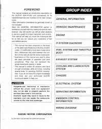
Group Index
2
-
How to Use this Manual
3
-
Component Parts and Work to be Done
3
-
Symbol
4
-
Abbreviations Used in this Manual
5
-
Wire Color
7
-
General Information
8
-
Contents
8
-
Warning/Caution/Note
9
-
Suzuki GSX-R600K4 (’04-Model) View
11
-
Serial Number Location
11
-
Fuel, Oil and Engine Coolant Recommendation Fuel (for USA and Canada)
12
-
Fuel (for Other Countries)
12
-
Engine Oil (for USA)
12
-
Engine Oil (for Other Countries)
12
-
Engine Coolant
13
-
Water for Mixing
13
-
Anti-Freeze/Engine Coolant
13
-
Liquid Amount of Water/Engine Coolant
13
-
Break-In Procedures
14
-
Cylinder Identification
14
-
Information Labels
15
-
Specifications
16
-
Dimensions and Dry Mass
16
-
Drive Train
16
-
Electrical
17
-
Capacities
17
-
Periodic Maintenance
18
-
Periodic Maintenance Schedule
19
-
Periodic Maintenance Chart
19
-
Lubrication Points
20
-
Maintenance and Tune-Up Procedures
21
-
Air Cleaner
21
-
Spark Plug and Ignition Coil/Plug Cap Removal
22
-
Heat Range
22
-
Carbon Deposits
22
-
Spark Plug Gap
23
-
Electrode’s Condition
23
-
Spark Plug and Ignition Coil/Plug Cap Installation
23
-
Valve Clearance
24
-
Valve Clearance Adjustment
26
-
Intake Side
27
-
Tappet Shim Selection Table
27
-
Exhaust Side
28
-
Engine Oil and Oil Filter
29
-
Engine Oil Replacement
29
-
Oil Filter Replacement
30
-
Fuel Line
31
-
Engine Idle Speed
31
-
Throttle Valve Synchronization
32
-
Evaporative Emission Control System (E-33 Only)
32
-
Pair (Air Supply) System
32
-
Throttle Cable Play
33
-
Clutch
33
-
Cooling System
34
-
Engine Coolant Level Check
34
-
Engine Coolant Change
34
-
Air Bleeding the Cooling Circuit
35
-
Radiator Hoses
36
-
Drive Chain
37
-
Checking
37
-
Adjusting
38
-
Cleaning and Lubricating
39
-
Brake Fluid Level Check
40
-
Brake Pads
41
-
Front Brake
41
-
Rear Brake
41
-
Brake Pedal Height
41
-
Brake Light Switch
42
-
Air Bleeding from Brake Fluid Circuit
42
-
Front Brake (Caliper Side)
42
-
Front Brake (Master Cylinder Side)
43
-
Tire Tread Condition
44
-
Tire Pressure
44
-
Steering
45
-
Front Fork
45
-
Rear Suspension
45
-
Exhaust Pipe Bolt and Muffler Bolt and Nut
46
-
Chassis Bolts and Nuts
47
-
Compression Pressure Check
49
-
Compression Pressure Specification
49
-
Compression Test Procedure
49
-
Oil Pressure Check
50
-
Oil Pressure Specification
50
-
Oil Pressure Test Procedure
50
-
Engine
52
-
Engine Components Removable with Engine in Place
53
-
Engine Center
53
-
Engine Right Side
53
-
Engine Left Side
53
-
Engine Removal
54
-
Radiator
55
-
Exhaust Pipe and Muffler
56
-
Electric Parts and Pair Hose
57
-
Engine Sprocket and Gear Shift Lever
58
-
Engine Mounting
59
-
Engine Installation
61
-
Engine Disassembly
67
-
Starter Motor
67
-
Cylinder Head Cover and Pair Reed Valve
67
-
Camshafts
68
-
Cylinder Head
69
-
Oil Pump
72
-
Gearshift System
72
-
Starter Idle Gear
73
-
Starter Clutch
74
-
Cam Chain, Cam Chain Tensioner and Cam Chain Guide
74
-
CKP Sensor
74
-
Generator Cover
75
-
Generator Rotor
75
-
Water Pump
75
-
Gear Position Switch
76
-
Crankcase Breather (PCV) Cover
76
-
Oil Filter
76
-
Lower Crank Case
77
-
Middle Crankcase
78
-
Crankshaft
78
-
Piston and Conrod
78
-
Engine Components Inspection and Service
80
-
Cylinder Head Cover
80
-
CMP Sensor
80
-
Pair Reed Valve
80
-
PCV Hose
81
-
Camshaft Identification
81
-
Cam Wear
81
-
Camshaft Journal Wear
82
-
Сamshaft Runout
83
-
Сam Sprocket
83
-
Сam Chain Tension Adjuster
83
-
Сam Chain Tensioner
84
-
Сam Chain Guide
84
-
Сylinder Head and Valve
84
-
Valve and Valve Spring Disassembly
84
-
Cylinder Head Distortion
86
-
Valve Stem Runout
86
-
Valve Head Radial Runout
86
-
Valve Stem and Valve Face Wear Condition
87
-
Valve Stem Deflection
87
-
Valve Stem Wear
87
-
Valve Guide Servicing
88
-
Valve Seat Width Inspection
89
-
Valve Seat Servicing
90
-
Initial Seat Cut
90
-
Top Narrowing Cut
91
-
Bottom Narrowing Cut
91
-
Final Seat Cut
92
-
Valve Spring
93
-
Valve and Valve Spring Reassembly
94
-
Intake Pipe
95
-
Water Bypass Union
96
-
Clutch Drive Plates Inspection
96
-
Clutch Spring Inspection
97
-
Clutch Bearing Inspection
97
-
Clutch Sleeve Hub/Primary Driven Gear Assembly
97
-
Generator
98
-
Gearshift Shaft/Gearshift Arm Disassembly
99
-
Gearshift Shaft/Gearshift Arm Inspection
99
-
Gearshift Shaft/Gearshift Arm Reassembly
99
-
Oil Pressure Regulator
100
-
Transmission
101
-
Disassembly
101
-
Reassembly
102
-
Transmission Parts Location
103
-
Cylinder Distortion
104
-
Cylinder Bore
104
-
Piston and Piston Ring
105
-
Piston Diameter
105
-
Piston-To-Cylinder Clearance
105
-
Piston Pin and Pin Bore
105
-
Piston Ring-To-Groove Clearance
106
-
Piston Ring Free End Gap and Piston Ring End Gap
106
-
Crankcase
107
-
Gearshift Fork and Gearshift Cam
107
-
Gearshift Fork-To-Groove Clearance
107
-
Gearshift Fork Groove Width
107
-
Gearshift Fork Thickness
108
-
Gearshift Cam Bearing and Gearshift Shaft Bearing
108
-
Bearing Inspection
108
-
Bearing Removal
108
-
Installation
109
-
Oil Jet
111
-
Inspection and Cleaning
111
-
Plug
112
-
Conrod Big End Side Clearance
113
-
Conrod-Big End Bearing Inspection
113
-
Conrod-Big End Bearing Selection
113
-
Crankshaft and Conrod
114
-
Crankshaft Runout
114
-
Conrod Small End I.D.
114
-
Crank Pin O.D.
115
-
Bearing Thickness
115
-
Bearing Selection Table
116
-
Conrod I.D.
116
-
Crankshaft Journal Bearing
118
-
Selection
118
-
Crankcase I.D. Specification
119
-
Crankshaft Journal O.D. Specification
120
-
Bearing Thickness Specification
120
-
Crankshaft Thrust Bearing
121
-
Crankshaft Thrust Clearance Adjustment
121
-
Thrust Bearing Selection Table
122
-
Engine Reassembly
123
-
Piston Ring
123
-
Oil Strainer
133
-
Oil Pan
133
-
Oil Pressure Switch
134
-
Crankcase Breather Cover
135
-
Cam Chain Drive Sprocket
138
-
Cam Chain Tensioner and Cam Chain Guide
138
-
Clutch Cover
146
-
Camshaft
149
-
Cam Chain Tension Adjuster
152
-
FI System Diagnosis
157
-
Precautions in Servicing
159
-
Electrical Parts
159
-
Connector/Coupler
159
-
Fuse
160
-
Ecm/Various Sensors
160
-
Electrical Circuit Inspection Procedure
162
-
Open Circuit Check
162
-
Continuity Check
163
-
Voltage Check
163
-
Short Circuit Check (Wire Harness to Ground)
164
-
Using the Multi-Circuit Tester
165
-
Using the Tester
165
-
FI System Technical Features
166
-
Injection Time (Injection Volume)
166
-
Compensation of Injection Time (Volume)
167
-
Injection Stop Control
167
-
Injection Timing
168
-
FI System Parts Location
169
-
FI System Wiring Diagram
171
-
Self-Diagnosis Function
172
-
User Mode
172
-
Dealer Mode
173
-
TPS Adjustment
175
-
Fail-Safe Function
176
-
FI System Troubleshooting
178
-
Self-Diagnostic Procedures
180
-
Self-Diagnosis Reset Procedure
180
-
Malfunction Code and Defective Condition
181
-
«C11» CMP Sensor Circuit Malfunction
183
-
«C12» CKP Sensor Circuit Malfunction
185
-
«C13» IAP Sensor Circuit Malfunction
187
-
«C14» TP Sensor Circuit Malfunction
190
-
«C15» ECT Sensor Circuit Malfunction
191
-
Output Voltage
193
-
«C21» IAT Sensor Circuit Malfunction
195
-
«C22» AP Sensor Circuit Malfunction
197
-
«C23» to Sensor Circuit Malfunction
200
-
«C28» STV Actuator Circuit Malfunction
202
-
«C29» STP Sensor Circuit Malfunction
204
-
«C31» GP Switch Circuit Malfunction
207
-
«C32», «C33», «C34» or «C35» Fuel Injector Circuit Malfunction
208
-
«C41» FP Relay Circuit Malfunction
210
-
«C42» IG Switch Circuit Malfunction
210
-
«C49» Pair Control Solenoid Valve Circuit Malfunction
211
-
Sensors
213
-
Fuel System and Throttle Body
216
-
Fuel Delivery System
217
-
Fuel System
218
-
Fuel Tank Lift-Up
218
-
Fuel Tank Removal
218
-
Fuel Pressure Inspection
219
-
Fuel Pump Inspection
220
-
Fuel Discharge Amount Inspection
220
-
Fuel Pump Relay Inspection
221
-
Fuel Pump and Fuel Filter Removal
222
-
Construction
222
-
Fuel Mesh Filter Inspection and Cleaning
224
-
Fuel Pump and Fuel Mesh Filter Installation
224
-
Throttle Body Construction
228
-
Air Cleaner Box Removal
229
-
Throttle Body Removal
230
-
Throttle Body Disassembly
231
-
Throttle Body Cleaning
233
-
Throttle Body Reassembly
234
-
Throttle Body Installation
236
-
Air Cleaner Box Installation
237
-
STP Sensor Adjustment
237
-
Fuel Injector Removal
238
-
Fuel Injector Inspection
238
-
Fuel Injector Installation
238
-
Fast Idle Adjustment
239
-
Use for Digital Vacuum Tester
241
-
Use for Vacuum Balancer Gauge
242
-
Calibrating each Vacuum Gauge
242
-
Throttle Position Sensor (TPS) Setting
244
-
Exhaust System
246
-
Precautions for Exhaust System
247
-
Exhaust System Components
247
-
Cooling and Lubrication System
250
-
Cooling Circuit Inspection
252
-
Radiator and Water Hoses
253
-
Radiator Removal
253
-
Radiator Cap Inspection
253
-
Radiator Inspection and Cleaning
253
-
Water Hose Inspection
254
-
Cooling Fan
255
-
Cooling Fan Thermo-Switch
256
-
ECT Sensor
257
-
Temperature Sensor Specification
257
-
Thermostat
258
-
Mechanical Seal
263
-
Oil Seal
263
-
Impeller Shaft Journal
263
-
Seal Washer
263
-
Lubrication System
267
-
Oil Cooler
267
-
Engine Lubrication System Chart
269
-
Engine Lubrication System
270
-
Chassis
273
-
Exterior Parts
275
-
Fastener Removal and Reinstallation
275
-
Screen
276
-
Body Cowling Cover and Lower Bracket Cover
276
-
Right and Left under Cowlings
276
-
Body Cowling
278
-
Right and Left Air Intake Pipes
279
-
Cowling Brace
279
-
Front Seat
279
-
Rear Seat and Seat Tail Cover
280
-
Frame Cover
280
-
Front Wheel Construction
281
-
Axle Shaft
283
-
Wheel Bearing
283
-
Reassembly and Installation
284
-
Brake Disc
285
-
Spacer Nut
286
-
Brake Caliper
286
-
Front Axle
286
-
Front Fork Construction
287
-
Inner and Outer Tubes
291
-
Damper Rod
292
-
Compression Damping Force Adjuster
292
-
Oil Seal and Dust Seal
292
-
Damper Rod Bolt
293
-
Fork Oil
293
-
Fork Spring
294
-
Front Fork Cap Bolt
295
-
Suspension Setting
298
-
Spring Pre-Load Adjustment
298
-
Damping Force Adjustment
298
-
Standard Front Suspension Setting
298
-
Steering Damper Construction
299
-
Steering Construction
301
-
Inner Race
303
-
Stem Nut
304
-
Front Fork and Steering Stem Upper Bracket
305
-
Steering Tension Adjustment
306
-
Handlebars Construction
307
-
Rear Wheel Construction
311
-
Rear Axle
313
-
Wheel Damper
313
-
Sprocket
314
-
Dust Seals
317
-
Rear Sprocket and Sprocket Mounting Drum
317
-
Rear Shock Absorber Construction
319
-
Rear Shock Absorber Scrapping Procedure
321
-
Rear Shock Absorber Gas Release
321
-
Rear Suspension Construction
323
-
Spacer
326
-
Swingarm Bearing
326
-
Cushion Lever Bearing
327
-
Cushion Lever and Cushion Lever Rods
327
-
Swingarm Pivot Shaft
327

Suzuki GSX-R600 Manual (165 pages)
Brand: Suzuki
|
Category: Motorcycle
|
Size: 2.75 MB
Table of Contents
-
Table of Contents
4
-
The Sport of Motorcycling
6
-
Most Accidents Can be Avoided
7
-
If You Don’t Have a Helmet, Buy a Helmet and Wear It Every Time You Ride
7
-
If a Collision Is Imminent, Do Something
8
-
Special Situations Require Special Care
9
-
Know Your Limits
9
-
Be Extra Safety-Conscious on Bad Weather Days
10
-
Practice Away from Traffic
10
-
Inspection before Riding
10
-
Accessories and Loading
10
-
Carrying a Passenger
11
-
Motorcycle Safety Foundation’s «Riding Tips and Practice Guide» Handbook (for Owners in Usa)
11
-
Be Street Smart
11
-
Labels
11
-
Conclusion
12
-
-
Fuel, Engine Oil and Coolant Recommendations
14
-
-
Controls, Equipment and Adjustments
22
-
Location of Parts
23
-
Ignition Switch
26
-
Key
26
-
Instrument Panel
29
-
Left Handlebar
43
-
Right Handlebar
46
-
Fuel Tank Cap
49
-
Gearshift Lever
50
-
Rear Brake Pedal
51
-
Seat Lock and Helmet Holders
51
-
Side Stand
53
-
Suspension Adjustment
54
-
Footrests and Gearshift Lever Position Change
59
-
Break-In and Inspection before Riding
62
-
-
Riding Tips
66
-
Starting the Engine
67
-
Starting off
69
-
Using the Transmission
70
-
Riding on Hills
71
-
Stopping and Parking
72
-
Carrying a Passenger
73
-
-
Accessory Use and Motorcycle Loading
74
-
Accessory Installation Guidelines
75
-
Accessory Use
75
-
Loading Limit
76
-
Loading Guidelines
77
-
Modification
77
-
-
Inspection and Maintenance
80
-
Maintenance Schedule
81
-
Steering Damper Maintenance
85
-
Tools
85
-
Lubrication Points
86
-
Battery
87
-
Air Cleaner
89
-
Spark Plugs
93
-
Engine Oil
99
-
Engine Idle Speed Inspection
105
-
Throttle Cable Play
105
-
Fuel Hose
106
-
Clutch Adjustment
107
-
Engine Coolant
107
-
Drive Chain
109
-
Brakes
113
-
Tires
118
-
Side Stand/Ignition Interlock System
121
-
Front Wheel Removal
122
-
Rear Wheel Removal
125
-
Light Bulb Replacement
128
-
Fuses
134
-
Catalytic Converter
136
-
Troubleshooting
138
-
Advertisement
Advertisement
Related Products
-
Suzuki GSX-R600 2006
-
Suzuki GSX-R600 2007
-
Suzuki GSX R600 2003
-
Suzuki GSX-R1000K5
-
Suzuki GSX-R750W 1993
-
Suzuki GSX-R250
-
Suzuki GSX-R1000/A
-
Suzuki GSX-R1000 2007
-
Suzuki GSX-R750UD
-
Suzuki GSX-R750UF
SUZUKI Categories
Motorcycle
Automobile
Musical Instrument
Offroad Vehicle
Outboard Motor
More SUZUKI Manuals
Материал из BikesWiki — энциклопедия японских мотоциклов
Перейти к: навигация, поиск

Suzuki GSX-R600
Ниже представлены прямые ссылки на скачку сервисной документации.
Для Suzuki GSX-R 600
- Сервисный мануал (Service Manual) на Suzuki GSX-R 600 (1997-2000)
- Сервисный мануал (Service Manual) на Suzuki GSX-R 600 (2001-2003)
- Сервисный мануал (Service Manual) на Suzuki GSX-R 600 (2004-2005)
- Сервисный мануал (Service Manual) на Suzuki GSX-R 600 (2006-2007)
- Сервисный мануал (Service Manual) на Suzuki GSX-R 600 (2008-2009)
- Сервисный мануал (Service Manual) на Suzuki GSX-R 600 (2010-2012)
Обзор модели
- Suzuki GSX-R 600
Источник — «https://bikeswiki.ru/index.php?title=Suzuki_GSX-R600:_мануалы&oldid=9844»
Категория:
- Сервисная документация
-
Contents
-
Table of Contents
-
Troubleshooting
-
Bookmarks
Quick Links
Troubleshooting
![]()
4-я Красноармейская, 2А
Санкт-Петербург, 190005
Email: info@lenmoto.ru
Телефон: +7 (921) 930-81-18
Телефон: +7 (911) 928-08-06
Компания ЛенМото
Запчасти, аксессуары, экипировка, тюнинг для мотоциклов, скутеров, квадроциклов, снегоходов, багги, гидроциклов, катеров и лодочных моторов.
Подпишитесь на наши новости
Подписаться
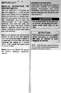
Руководство на английском языке по эксплуатации и техническому обслуживанию мотоциклов Suzuki GSX-R250.
- Издательство: Suzuki Motor Corporation
- Год издания: —
- Страниц: 22
- Формат: PNG
- Размер: 6,2 Mb
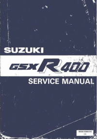
Руководство на английском языке по ремонту мотоциклов Suzuki GSX-R400.
- Издательство: Suzuki Motor Corporation
- Год издания: —
- Страниц: 246
- Формат: PDF
- Размер: 22,3 Mb
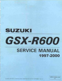
Руководство на английском языке по ремонту мотоциклов Suzuki GSX-R600 1997-2000 годов выпуска.
- Издательство: Suzuki Motor Corporation
- Год издания: —
- Страниц: 429
- Формат: PDF
- Размер: 48,5 Mb
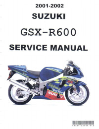
Руководство на английском языке по ремонту мотоциклов Suzuki GSX-R600 2001-2002 годов выпуска.
- Издательство: Suzuki Motor Corporation
- Год издания: —
- Страниц: 399
- Формат: PDF
- Размер: 41,8 Mb
Руководство на английском языке по ремонту мотоциклов Suzuki GSX-R600.
- Издательство: Suzuki Motor Corporation
- Год издания: 2003
- Страниц: 466
- Формат: PDF
- Размер: 48,9 Mb
Руководство на английском языке по ремонту мотоциклов Suzuki GSX-R600.
- Издательство: Suzuki Motor Corporation
- Год издания: 2006
- Страниц: 517
- Формат: PDF
- Размер: 45,9 Mb
Руководство на английском языке по ремонту мотоциклов Suzuki GSX-R750.
- Издательство: Suzuki Motor Corporation
- Год издания: 1995
- Страниц: 558
- Формат: PDF
- Размер: 188,3 Mb
Руководство на английском языке по ремонту мотоциклов Suzuki GSX-R750 2000-2002 годов выпуска.
- Издательство: Suzuki Motor Corporation
- Год издания: —
- Страниц: 498
- Формат: PDF
- Размер: 142,6 Mb
Руководство на английском языке по ремонту мотоциклов Suzuki GSX-R750.
- Издательство: Suzuki Motor Corporation
- Год издания: 2004
- Страниц: 471
- Формат: PDF
- Размер: 40,8 Mb
Руководство на английском языке по ремонту мотоциклов Suzuki GSX-R750.
- Издательство: Suzuki Motor Corporation
- Год издания: 2006
- Страниц: 522
- Формат: PDF
- Размер: 46,0 Mb
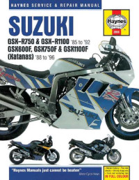
Руководство на английском языке по техническому обслуживанию и ремонту мотоциклов Suzuki GSX600F Katana, GSX750F Katana, GSX1100F Katana 1988-1996 годов выпуска и GSX-R750, GSX-R1100 1985-1992 годов выпуска.
- Издательство: Haynes Publishing
- Год издания: —
- Страниц: 256
- Формат: PDF
- Размер: 37,5 Mb
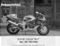
Руководство на французском языке по техническому обслуживанию и ремонту мотоциклов Suzuki GSX-R750T 1996 года выпуска.
- Издательство: —
- Год издания: —
- Страниц: 86
- Формат: PDF
- Размер: 43,1 Mb
Руководство на английском языке по ремонту мотоциклов Suzuki GSX-R750W.
- Издательство: Suzuki Motor Corporation
- Год издания: 1992
- Страниц: 352
- Формат: PDF
- Размер: 50,6 Mb
Руководство на английском языке по ремонту мотоциклов Suzuki GSX-R1000.
- Издательство: Suzuki Motor Corporation
- Год издания: 2000
- Страниц: 424
- Формат: PDF
- Размер: 211,4 Mb
Руководство на английском языке по ремонту мотоциклов Suzuki GSX-R1000.
- Издательство: Suzuki Motor Corporation
- Год издания: 2003
- Страниц: 460
- Формат: PDF
- Размер: 18,8 Mb
Руководство на английском языке по ремонту мотоциклов Suzuki GSX-R1000.
- Издательство: Suzuki Motor Corporation
- Год издания: 2007
- Страниц: 549
- Формат: PDF
- Размер: 48,8 Mb
Руководство на английском языке по эксплуатации и техническому обслуживанию мотоциклов Suzuki GSX-R1100.
- Издательство: Suzuki Motor Corporation
- Год издания: 1988
- Страниц: 90
- Формат: PDF
- Размер: 38,1 Mb
Руководство на английском языке по ремонту мотоциклов Suzuki GSX-R1100.
- Издательство: Suzuki Motor Corporation
- Год издания: 1986
- Страниц: 295
- Формат: PDF
- Размер: 105,4 Mb
Руководство на английском языке по ремонту мотоциклов Suzuki GSX-R1100.
- Издательство: Suzuki Motor Corporation
- Год издания: 1990
- Страниц: 358
- Формат: PDF
- Размер: 50,7 Mb
Руководство на английском языке по ремонту мотоциклов Suzuki GSX-R1100W.
- Издательство: Suzuki Motor Corporation
- Год издания: 1992
- Страниц: 380
- Формат: PDF
- Размер: 52,8 Mb
Руководство на английском языке по ремонту мотоциклов Suzuki GSX-R1300R.
- Издательство: Suzuki Motor Corporation
- Год издания: 2007
- Страниц: 663
- Формат: PDF
- Размер: 26,9 Mb
