- Manuals
- Brands
- Yamaha Manuals
- Motorcycle
- FZ1
- Owner’s manual
-
Contents
-
Table of Contents
-
Troubleshooting
-
Bookmarks
Related Manuals for Yamaha FZ1
Summary of Contents for Yamaha FZ1
-
Page 1
OWNER’S MANUAL FZS1000R FZS1000RC FZS1000SR FZS1000SRC LIT-11626-16-33 5LV-28199-12… -
Page 2
EAU03438… -
Page 3
EAU00002 Congratulations on your purchase of the Yamaha FZS1000/FZS1000S. This model is the result of Yamaha’s vast experience in the production of fine sporting, touring, and pacesetting racing machines. It represents the high degree of craftsmanship and reliability that have made Yamaha a leader in these fields. -
Page 4
This manual should be considered a permanent part of this motorcycle and should remain with it even if the motorcycle is subsequently sold. Yamaha continually seeks advancements in product design and quality. Therefore, while this manual contains the most current product information available at the time of printing, there may be minor discrepancies between your motorcycle and this manual. -
Page 5: Important Manual Information
IMPORTANT MANUAL INFORMATION EW000000 WARNING PLEASE READ THIS MANUAL AND THE “YOU AND YOUR MOTORCYCLE: RIDING TIPS” BOOKLET CAREFULLY AND COMPLETELY BEFORE OPERATING THIS MOTOR- CYCLE. DO NOT ATTEMPT TO OPERATE THIS MOTORCYCLE UNTIL YOU HAVE AT- TAINED ADEQUATE KNOWLEDGE OF ITS CONTROLS AND OPERATING FEATURES AND UNTIL YOU HAVE BEEN TRAINED IN SAFE AND PROPER RIDING TECHNIQUES.
-
Page 6
IMPORTANT MANUAL INFORMATION AFFIX DEALER LABEL HERE EAU04247 FZS1000R/FZS1000RC/FZS1000SR/FZS1000SRC OWNER’S MANUAL ©2002 by Yamaha Motor Corporation, U.S.A. 1st edition, May 2002 All rights reserved. Any reprinting or unauthorized use without the written permission of Yamaha Motor Corporation, U.S.A. is expressly prohibited. -
Page 7: Table Of Contents
TABLE OF CONTENTS EAU00009 1 SAFETY INFORMATION 2 DESCRIPTION 3 INSTRUMENT AND CONTROL FUNCTIONS 4 PRE-OPERATION CHECKS 5 OPERATION AND IMPORTANT RIDING POINTS 6 PERIODIC MAINTENANCE AND MINOR REPAIR 7 MOTORCYCLE CARE AND STORAGE 8 SPECIFICATIONS 9 CONSUMER INFORMATION INDEX…
-
Page 8: Safety Information
SAFETY INFORMATION Safe riding ………………1-1 Protective apparel …………….1-3 Modifications ………………1-3 Loading and accessories …………..1-3 Gasoline and exhaust gas…………..1-5 Location of important labels ………….. 1-7…
-
Page 9: Safe Riding
S AFETY INFORMATION EAU00014 MOTORCYCLES ARE SINGLE TRACK VEHICLES. THEIR SAFE USE AND OPERATION ARE DEPENDENT UPON THE USE OF PROPER RIDING TECHNIQUES AS WELL AS THE EXPERTISE OF THE OPERATOR. EVERY OPERATOR SHOULD KNOW THE FOLLOWING REQUIREMENTS BEFORE RIDING THIS MOTORCYCLE. HE OR SHE SHOULD: 1.
-
Page 10: Safety Information
SAFETY INFORMATION 4. Many accidents involve inexperienced operators. In fact, many operators who have been involved in accidents do not even have a current motorcycle license. a. Make sure that you are qualified and that you only lend your motorcycle to other qualified operators.
-
Page 11: Safety Information
6. A passenger should also observe the above precautions. Modifications Modifications made to this motorcycle not approved by Yamaha, or the removal of original equipment, may render the motorcycle unsafe for use and may cause severe personal injury. Modifications may also make your motorcycle illegal to use.
-
Page 12: Safety Information
Genuine Yamaha accessories have been specifically designed for use on this motorcycle. Since Yamaha cannot test all other accessories that may be available, you must personally be responsible for the proper selection, installation and use of non-Yamaha accessories. Use extreme caution when selecting and installing any accessories.
-
Page 13: Gasoline And Exhaust Gas
SAFETY INFORMATION a. Accessories fitted to the handlebar or the front fork area can create instability due to improper weight distribution or aerodynamic changes. If accessories are added to the handlebar or front fork area, they must be as lightweight as possible and should be kept to a minimum. b.
-
Page 14
SAFETY INFORMATION a. The engine and exhaust system may be hot, therefore, park the motorcycle in a place where pe- destrians or children are not likely to touch these hot areas. b. Do not park the motorcycle on a slope or soft ground, otherwise it may fall over. c. -
Page 15: Location Of Important Labels
SAFETY INFORMATION EAU02977 Location of important labels Please read the following important labels carefully before operating this motorcycle.
-
Page 16
SAFETY INFORMATION California only CAUTION Cleaning with alkaline or acid cleaner, gasoline or solvent will damage windshield. Use neutral detergent. 5JW-00 (5JW-2835Y-00) -
Page 17: Description
DESCRIPTION Left view ………………… 2-1 Right view………………. 2-2 Controls and instruments …………..2-3…
-
Page 18: Left View
D ESCRIPTION EAU00026 Left view 1. Front fork compression damping 8. Seat lock/helmet holder (page 3-11) force adjusting screw (page 3-14) 9. Shock absorber assembly 2. Front fork rebound damping force compression damping force adjusting screw (page 3-13) adjusting screw (page 3-16) 3.
-
Page 19: Right View
DESCRIPTION Right view 13. Owner’s tool kit (page 6-1) 18. Engine oil filter cartridge (page 6-13) 14. Rear brake fluid reservoir (page 6-30) 19. Engine oil level check window (page 6-12) 15. Battery (page 6-37) 20. Brake pedal (page 3-8) 16.
-
Page 20
DESCRIPTION Controls and instruments 1. Clutch lever (page 3-7) 6. Tachometer unit (page 3-4) 2. Left handlebar switches (page 3-6) 7. Fuel gauge (page 3-5) 3. Starter (choke) lever (page 3-10) 8. Right handlebar switches (page 3-6) 4. Speedometer unit (page 3-3) 9. -
Page 21: Instrument And Control Functions
INSTRUMENT AND CONTROL FUNCTIONS Main switch/steering lock …………..3-1 Indicator and warning lights …………. 3-2 Speedometer unit …………….3-3 Tachometer unit …………….. 3-4 Self-diagnosis devices …………… 3-5 Fuel gauge ………………3-5 Handlebar switches …………….3-6 Clutch lever ………………3-7 Shift pedal ………………3-7 Brake lever ………………
-
Page 22: Main Switch/Steering Lock
I NSTRUMENT AND CONTROL FUNCTIONS EAU00027 1. Push. 2. Turn. EAU00029 EAU00040 Main switch/steering lock LOCK EW000016 The steering is locked, and all electrical WARNING The main switch/steering lock controls systems are off. The key can be the ignition and lighting systems, and is Never turn the key to “OFF”…
-
Page 23: Instrument And Control Functions
4. Oil level warning light “ ” “ON”. Yamaha dealer check the electrical cir- 5. Right turn signal indicator light “ ” If the warning light does not come on 6. Coolant temperature warning light “…
-
Page 24: Speedometer Unit
If the warning light does not come on fuel gauge to estimate the distance that for a few seconds, then go off, have a can be traveled on a full tank of fuel. Yamaha dealer check the electrical cir- cuit.
-
Page 25: Tachometer Unit
INSTRUMENT AND CONTROL FUNCTIONS To set the clock: 1. Push both the “SELECT” and “RESET” buttons for at least two seconds. 2. When the hour digits start flashing, push the “RESET” button to set the hours. 3. Push the “SELECT” button to change the minutes.
-
Page 26: Self-Diagnosis Devices
If the tachometer displays such an er- Self-diagnosis devices ror code, note the circuit-specific num- This model is equipped with a self-di- ber of r/min, and then have a Yamaha agnosis device for the following electri- dealer check the motorcycle. cal circuits:…
-
Page 27: Handlebar Switches
INSTRUMENT AND CONTROL FUNCTIONS EAU03889 Turn signal switch “ ” To signal a right-hand turn, push this switch to “ ”. To signal a left-hand turn, push this switch to “ ”. When released, the switch returns to the cen- ter position.
-
Page 28: Clutch Lever
INSTRUMENT AND CONTROL FUNCTIONS 1. Clutch lever 1. Shift pedal 1. Brake lever 2. Brake lever position adjusting dial EAU00152 EAU00157 3. Arrow mark Clutch lever Shift pedal a. Distance between brake lever and handlebar The clutch lever is located at the left The shift pedal is located on the left grip handlebar grip.
-
Page 29: Brake Pedal
INSTRUMENT AND CONTROL FUNCTIONS 2. Turn the key counterclockwise to the original position, remove it, and then close the lock cover. NOTE: The fuel tank cap cannot be closed un- less the key is in the lock. In addition, the key cannot be removed if the cap is not properly closed and locked.
-
Page 30: Fuel
INSTRUMENT AND CONTROL FUNCTIONS EAU00185 EAU04265 CAUTION: Recommended fuel: Immediately wipe off spilled fuel UNLEADED GASOLINE ONLY with a clean, dry, soft cloth, since Fuel tank capacity: fuel may deteriorate painted surfac- Total amount: es or plastic parts. 21 L (4.6 Imp gal, 5.5 US gal) Reserve amount: 4 L (0.9 Imp gal, 1.1 US gal) 1.
-
Page 31: Starter (Choke) Lever
INSTRUMENT AND CONTROL FUNCTIONS Your Yamaha engine has been de- signed to use regular unleaded gaso- line with a pump octane number [(R+M)/2] of 86 or higher, or a research octane number of 91 or higher. If knocking (or pinging) occurs, use a gasoline of a different brand or premi- um unleaded fuel.
-
Page 32: Seat
INSTRUMENT AND CONTROL FUNCTIONS 1. Seat lock 1. Projection 1. Helmet holder 2. Unlock. 2. Seat holder 2. Unlock. EAU03956 To install the seat EAU04291 Seat Helmet holder 1. Insert the projection on the front of To open the helmet holder, insert the the seat into the seat holder as To remove the seat key into the seat lock, and then turn the…
-
Page 33: Storage Compartment
INSTRUMENT AND CONTROL FUNCTIONS When storing the owner’s manual or EAU04293 Adjusting the front fork other documents in the storage com- This front fork is equipped with spring partment, be sure to wrap them in a preload adjusting bolts, rebound damp- plastic bag so that they will not get wet.
-
Page 34
INSTRUMENT AND CONTROL FUNCTIONS 1. Spring preload adjusting bolt 1. Current setting 1. Rebound damping force adjusting screw 2. Front fork cap bolt Spring preload Rebound damping force To increase the spring preload and To increase the rebound damping NOTE: Align the appropriate groove on the ad- thereby harden the suspension, turn force and thereby harden the rebound… -
Page 35: Adjusting The Shock Absorber Assembly
INSTRUMENT AND CONTROL FUNCTIONS EC000015 EAU04295* Adjusting the shock absorber CAUTION: assembly Never attempt to turn an adjusting This shock absorber assembly is mechanism beyond the maximum equipped with a spring preload adjust- or minimum settings. ing ring, a rebound damping force ad- justing knob and a compression NOTE: Although the total number of clicks of a…
-
Page 36
INSTRUMENT AND CONTROL FUNCTIONS NOTE: Align the appropriate notch in the adjusting ring with the position in- dicator on the shock absorber. Use the special wrench included in the owner’s tool kit to make the ad- justment. Setting 1. Spring preload adjusting ring 1. -
Page 37
7 clicks in direction a* Standard will result in poor damping per- 12 clicks in direction a* Maximum (hard) formance. * With the adjusting screw fully turned in direction b Always have a Yamaha dealer service the shock absorber. 3-16… -
Page 38: Exup System
Yamaha factory. Changing scribed below and have a Yamaha these settings without sufficient dealer repair it if it does not function technical knowledge may result properly. in poor performance of or dam- age to the engine.
-
Page 39: Ignition Circuit Cut-Off System
If a malfunction is noted, have a It prevents starting when the trans- Yamaha dealer check the sys- mission is in gear and the side- tem before riding. stand is up, but the clutch lever is not pulled.
-
Page 40
5. Push the start switch. Does the engine start? The neutral switch may be defective. The motorcycle should not be ridden until checked by a Yamaha dealer. With the engine still running: 6. Move the sidestand up. 7. Keep the clutch lever pulled. -
Page 41: Pre-Operation Checks
PRE-OPERATION CHECKS Pre-operation check list …………..4-1…
-
Page 42: Pre-Operation Check List
• If necessary, add recommended coolant to specified level. 6-15–6-16 • Check cooling system for leakage. • Check operation. • If soft or spongy, have Yamaha dealer bleed hydraulic system. Front brake • Check fluid level in reservoir. 6-29–6-30 • If necessary, add recommended brake fluid to specified level.
-
Page 43
• Make sure that operation is smooth. • Check cable free play. 6-22, Throttle grip • If necessary, have Yamaha dealer adjust cable free play and lubricate cable and 6-33 grip housing. • Make sure that operation is smooth. Control cables 6-33 •… -
Page 44
PRE-OPERATION CHECKS NOTE: Pre-operation checks should be made each time the motorcycle is used. Such an inspection can be accomplished in a very short time; and the added safety it assures is more than worth the time involved. EWA00033 WARNING If any item in the Pre-operation check list is not working properly, have it inspected and repaired before operating the motorcycle. -
Page 45: Operation And Important Riding Points
OPERATION AND IMPORTANT RIDING POINTS Starting and warming up a cold engine ……….5-1 Starting a warm engine …………..5-3 Shifting ………………..5-4 Engine break-in …………….. 5-5 Parking ………………..5-6…
-
Page 46: Starting And Warming Up A Cold Engine
Consult a Yamaha dealer re- blocked and performance will The transmission is in the neutral garding any control or function suffer.
-
Page 47
If necessary, add engine should be on, otherwise have a If the fuel level warning light re- Yamaha dealer check the electrical cir- oil, and then check the warning mains on after starting, stop the light again. If, when the key is cuit. -
Page 48: Starting A Warm Engine
(choke) turned off. To avoid the possi- fuel, have a Yamaha dealer that the starter (choke) is not required bility of excessive exhaust emissions, check the electrical circuit.
-
Page 49: Shifting
OPERATION AND IMPORTANT RIDING POINTS EC000048 EAU02988 To start out and accelerate CAUTION: 1. Pull the clutch lever to disengage Even with the transmission in the clutch. the neutral position, do not 2. Shift the transmission into first coast for long periods of time gear.
-
Page 50: Engine Break-In
OPERATION AND IMPORTANT RIDING POINTS EAU00427 EAU02989 EAU01128 To decelerate Recommended shift points Engine break-in 1. Apply both the front and the rear The recommended shift points during There is never a more important period brakes to slow the motorcycle. acceleration and deceleration are in the life of your engine than the period 2.
-
Page 51: Parking
1,600 km (1,000 mi) and beyond The vehicle can now be operated normally. EC000053 CAUTION: Keep the engine speed out of the tachometer red zone. If any engine trouble should oc- cur during the engine break-in period, immediately have Yamaha dealer check the vehicle.
-
Page 52: Periodic Maintenance And Minor Repair
PERIODIC MAINTENANCE AND MINOR REPAIR Periodic maintenance ……….6-1 Lubricating the drive chain …….. 6-32 Owner’s tool kit …………6-1 Checking and lubricating the cables ….6-33 Periodic maintenance chart for the emission Checking and lubricating the throttle grip and control system ………..6-3 cable ……………
-
Page 53: Periodic Maintenance
RELATED TO EMISSIONS CON- cycle maintenance work, have a manual and the tools provided in the TROL ARE GROUPED SEPARATE- Yamaha dealer do it for you. owner’s tool kit are intended to assist LY. THESE SERVICES REQUIRE you in the performance of preventive SPECIALIZED DATA, KNOWLEDGE, maintenance and minor repairs.
-
Page 54
PERIODIC MAINTENANCE AND MINOR REPAIR NOTE: If you do not have the tools or experi- ence required for a particular job, have a Yamaha dealer perform it for you. EW000062 WARNING Modifications approved Yamaha may cause loss of perfor- mance, excessive emissions, and render the vehicle unsafe for use. -
Page 55: Periodic Maintenance Chart For The Emission Control System
PERIODIC MAINTENANCE AND MINOR REPAIR EAU00471 Periodic maintenance chart for the emission control system CP-03E INITIAL ODOMETER READINGS 600 mi 4,000 mi 8,000 mi 12,000 mi 16,000 mi 20,000 mi ITEM ROUTINE (1,000 km) (7,000 km) (13,000 km) (19,000 km) (25,000 km) (31,000 km) 1 month…
-
Page 56
• Check the air cut valve and reed valve Air induction for damage. √ √ √ √ √ system • Replace the entire air induction system if necessary. * Since these items require special tools, data and technical skills, have a Yamaha dealer perform the service. -
Page 57: General Maintenance And Lubrication Chart
PERIODIC MAINTENANCE AND MINOR REPAIR EAU00472 General maintenance and lubrication chart INITIAL ODOMETER READINGS 600 mi 4,000 mi 8,000 mi 12,000 mi 16,000 mi 20,000 mi ITEM ROUTINE (1,000 km) (7,000 km) (13,000 km) (19,000 km) (25,000 km) (31,000 km) 1 month 6 months 12 months…
-
Page 58
PERIODIC MAINTENANCE AND MINOR REPAIR INITIAL ODOMETER READINGS 600 mi 4,000 mi 8,000 mi 12,000 mi 16,000 mi 20,000 mi ITEM ROUTINE (1,000 km) (7,000 km) (13,000 km) (19,000 km) (25,000 km) (31,000 km) 1 month 6 months 12 months 18 months 24 months 30 months… -
Page 59
21 * • Check the screw clamp for looseness. exhaust pipe * Since these items require special tools, data and technical skills, have a Yamaha dealer perform the service. #1 : Yamaha chain lube #2 : Lithium-soap-based grease (all-purpose grease) -
Page 60: Removing And Installing Panels
PERIODIC MAINTENANCE AND MINOR REPAIR 1. Panel A 1. Panel C 1. Panel A 2. Panel B 2. Screw EAU01122 EAU04003 Removing and installing Panels A and C To remove one of the panels panels Remove the screw, and then pull the The panels shown above need to be panel off as shown.
-
Page 61
PERIODIC MAINTENANCE AND MINOR REPAIR 1. Panel C 1. Panel B 2. Screw 2. Screw (× 3) To install the panel EAU01315 Place the panel in the original position, Panel B and then install the screw To remove the panel Remove the screws, and then take the panel off. -
Page 62: Checking The Spark Plugs
Do not attempt to diagnose such problems yourself. Instead, have a Yamaha dealer check the motorcycle. 3. Check each spark plug for elec- trode erosion and excessive car- bon or other deposits, and replace 1.
-
Page 63: Canister (For California Only)
PERIODIC MAINTENANCE AND MINOR REPAIR 3. Install the spark plug with the spark plug wrench, and then tight- en it to the specified torque. Tightening torque: Spark plug: 12.5 Nm (1.25 m·kgf, 9.0 ft·lbf) NOTE: a. Spark plug gap If a torque wrench is not available when installing a spark plug, a good estimate To install a spark plug EAU01796…
-
Page 64: Engine Oil And Oil Filter Cartridge
PERIODIC MAINTENANCE AND MINOR REPAIR EAU04625 To change the engine oil (with or Engine oil and oil filter without oil filter cartridge replace- cartridge ment) The engine oil level should be checked 1. Start the engine, warm it up for before each ride.
-
Page 65
NOTE: An oil filter wrench is available at a Skip steps 4–6 if the oil filter car- Make sure that the O-ring is properly Yamaha dealer. tridge is not being replaced. seated. When draining the engine oil, use a funnel or similar device to keep the oil away from the exhaust pipe. -
Page 66
PERIODIC MAINTENANCE AND MINOR REPAIR 8. Add the specified amount of the ECA00133 CAUTION: recommended engine oil, and In order to prevent clutch slip- then install and tighten the oil filler page (since the engine oil also cap. lubricates the clutch), do not mix any chemical additives. -
Page 67: Coolant
If the oil level warning light flickers before each ride. In addition, the cool- or remains on, immediately turn the ant must be changed at the intervals engine off and have a Yamaha deal- specified in the periodic maintenance er check the vehicle. and lubrication chart.
-
Page 68
If water has been added to the coolant, have a Yamaha dealer check the antifreeze content of the coolant as soon as possible, otherwise the effectiveness of the coolant will be reduced. -
Page 69
PERIODIC MAINTENANCE AND MINOR REPAIR EAU04299 To change the coolant 1. Place the motorcycle on the cen- terstand and let the engine cool if necessary. 2. Remove panels A and B. (See pages 6-8 and 6-9 for panel re- moval installation proce- dures.) -
Page 70
12. Start the engine, and then check coolant, have a Yamaha dealer the vehicle for coolant leakage. If check the antifreeze content of coolant is leaking, have a Yamaha the coolant as soon as possible, dealer check the cooling system. otherwise the effectiveness of 13. -
Page 71: Cleaning The Air Filter Element
PERIODIC MAINTENANCE AND MINOR REPAIR EAU04051* Cleaning the air filter element The air filter element should be cleaned at the intervals specified in the periodic maintenance and lubrication chart. Clean the air filter element more fre- quently if you are riding in unusually wet or dusty areas.
-
Page 72
PERIODIC MAINTENANCE AND MINOR REPAIR 1. Air filter case cover 1. Air filter element 1. Air filter element 2. Screw (× 4) 7. Pull the air filter element out. 8. Lightly tap the air filter element to 6. Remove the air filter case cover by remove most of the dust and dirt, removing the screws. -
Page 73: Adjusting The Carburetors
Therefore, all carburetor cylinders may become excessively adjustments should be left to a worn. Yamaha dealer, who has the neces- 10. Install the air filter case cover by sary professional knowledge installing the screws.
-
Page 74: Adjusting The Throttle Cable Free Play
The valve clearance changes with use, resulting in improper air-fuel mixture and/or engine noise. To prevent this from occurring, the valve clearance must be adjusted by a Yamaha dealer at the intervals specified in the periodic maintenance and lubrication chart. a. Throttle cable free play…
-
Page 75: Tires
PERIODIC MAINTENANCE AND MINOR REPAIR EAU03581 CE-22E EW000083 Tire air pressure Tires WARNING (measured on cold tires) To maximize the performance, durabil- Load* Front Rear Proper loading of your motorcycle ity, and safe operation of your motor- 250 kPa 270 kPa is important for several characteris- Up to 90 kg (198 lb) (2.50 kgf/cm…
-
Page 76
(minimum tread depth), if the tire has a nail or glass fragments in it, or if the side wall is cracked, con- tact a Yamaha dealer immediately and have the tire replaced. CE-09E Minimum tire tread depth 1.0 mm (0.04 in) -
Page 77
Tire air valve TR412 Yamaha Motor Co., Ltd. Brand-new tires can have a rela- Valve core #9000A (original) Always make sure that the valve tively poor grip on certain road caps are securely installed to surfaces until they have been prevent air pressure leakage. -
Page 78: Cast Wheels
The accessories or replace- fore each ride. If any damage is ment parts you choose for your found, have a Yamaha dealer re- motorcycle should be designed spe- place the wheel. Do not attempt cifically for this model, and they…
-
Page 79: Adjusting The Clutch Lever Free Play
Periodically check the clutch lever free Periodically check the brake pedal posi- play and, if necessary, adjust it as fol- tion and, if necessary, have a Yamaha lows. dealer adjust it. To increase the clutch lever free play, turn the adjusting bolt in direction a.
-
Page 80: Adjusting The Rear Brake Light Switch
If there is air in the hydraulic system, have a Yamaha dealer bleed the system be- fore operating the motorcycle. Air in the hydraulic system will diminish 1. Rear brake light switch the braking performance, which 2.
-
Page 81: Checking The Front And Rear Brake Pads
Yamaha dealer replace Before riding, check that the brake fluid ified in the periodic maintenance and the brake pads as a set.
-
Page 82: Changing The Brake Fluid
EAU03976 Rear brake Changing the brake fluid ter the brake fluid reservoir when Have a Yamaha dealer change the refilling. Water will significantly brake fluid at the intervals specified in lower the boiling point of the fluid the NOTE after the periodic mainte- and may result in vapor lock.
-
Page 83: Drive Chain Slack
PERIODIC MAINTENANCE AND MINOR REPAIR Drive chain slack: 40–50 mm (1.6–2.0 in) 5. If the drive chain slack is incorrect, adjust it as follows. a. Drive chain slack 1. Axle nut b. Measurement point: 135 mm (5.3 in) 2. Drive chain slack adjusting bolt 3.
-
Page 84: Lubricating The Drive Chain
PERIODIC MAINTENANCE AND MINOR REPAIR EAU03006 2. Wipe the drive chain dry. NOTE: Lubricating the drive chain Using the alignment marks on each 3. Thoroughly lubricate the drive The drive chain must be cleaned and side of the swingarm, make sure that chain with a special O-ring chain lubricated at the intervals specified in both chain pullers are in the same posi-…
-
Page 85: Checking And Lubricating The Cables
If a cable is damaged the periodic maintenance chart. or does not move smoothly, have a Yamaha dealer check or replace it. EAU03370 Checking and lubricating the Recommended lubricant: brake and shift pedals…
-
Page 86: Checking And Lubricating The Brake And Clutch Levers
Recommended lubricant: EW000114 WARNING Lithium-soap-based grease If the centerstand or sidestand does (all-purpose grease) not move up and down smoothly, have a Yamaha dealer check or re- pair it. 6-34…
-
Page 87: Lubricating The Rear Suspension
EC000098 CAUTION: If any damage is found or the front fork does not operate smoothly, have a Yamaha dealer check or re- pair it. 6-35…
-
Page 88: Checking The Steering
EW000115 fork legs and try to move them for- WARNING ward and backward. If any free Securely support the motorcycle so play can be felt, have a Yamaha that there is no danger of it falling dealer check repair over.
-
Page 89: Battery
• EXTERNAL: Flush with plenty To charge the battery Battery of water. Have a Yamaha dealer charge the bat- This motorcycle is equipped with a • INTERNAL: Drink large quan- tery as soon as possible if it seems to sealed-type (MF) battery, which does tities of water or milk and im- have discharged.
-
Page 90: Replacing The Fuses
10 A 5. Signaling system fuse cess to a sealed-type (MF) bat- 6. Odometer and clock fuse (backup fuse) EC000103 tery charger, have a Yamaha 7. Spare fuse (× 2) CAUTION: dealer charge your battery. 8. Spare main fuse Do not use a fuse of a higher amper-…
-
Page 91: Replacing A Headlight Bulb
PERIODIC MAINTENANCE AND MINOR REPAIR 1. Headlight bulb cover 1. Headlight bulb holder 1. Do not touch the glass part of the bulb. 2. Headlight coupler 3. Unhook the headlight bulb holder, EW000119 EAU04226 WARNING and then remove the defective Replacing a headlight bulb Headlight bulbs get very hot.
-
Page 92
Take care not to damage the follow- 6. Install the panel. ing parts: 7. Have a Yamaha dealer adjust the Headlight bulb headlight beam if necessary. Do not touch the glass part of the headlight bulb to keep it free… -
Page 93: Replacing A Tail/Brake Light Bulb
PERIODIC MAINTENANCE AND MINOR REPAIR 1. Tail/brake light bulb cover 1. Socket 1. Screw 3. Remove the socket (together with EAU03961 EAU03497 Replacing a tail/brake light Replacing a turn signal light the bulb) by turning it counter- bulb bulb clockwise. 1.
-
Page 94: Front Wheel
4. Remove the brake caliper on each EW000122 side by removing the bolts. WARNING ECA00046 It is advisable to have a Yamaha CAUTION: dealer service the wheel. Do not apply the brake after the Securely support the motor- brake calipers have been removed,…
-
Page 95: Rear Wheel
EW000122 WARNING 5. Install the brake hose holders by installing the bolts. It is advisable to have a Yamaha 6. Tighten the wheel axle, the wheel dealer service the wheel. axle pinch bolt and the brake cali- Securely support the motor- per bolts to the specified torques.
-
Page 96
PERIODIC MAINTENANCE AND MINOR REPAIR 1. Bolt (× 2) 1. Axle nut 2. Brake torque rod 2. Drive chain slack adjusting bolt 3. Brake torque rod bolt 3. Locknut 4. Brake torque rod nut 6. Turn the drive chain slack adjust- 5. -
Page 97: Troubleshooting
However, should your motorcycle bolts and brake torque rod nut to iper bracket in the original position. require any repair, take it to a Yamaha the specified torques. 2. Insert the wheel axle through the dealer, whose skilled technicians have…
-
Page 98: Troubleshooting Charts
Remove the spark plugs and check the electrodes. The engine does not start. Have a Yamaha dealer check the vehicle. Check the battery. 4. Battery The engine turns over The battery is good.
-
Page 99
Start the engine. If the engine overheats again, have a The coolant level Yamaha dealer check and repair the cooling system. is OK. NOTE: If coolant is not available, tap water can be temporarily used instead, provided that it is changed to the recommended coolant as soon as possible. -
Page 100: Motorcycle Care And Storage
MOTORCYCLE CARE AND STORAGE Care ………………..7-1 Storage ………………..7-4…
-
Page 101
M OTORCYCLE CARE AND STORAGE EAU03426 Care Before cleaning Cleaning 1. Cover the muffler outlet with a ECA00010 While the open design of a motorcycle CAUTION: plastic bag after the engine has reveals the attractiveness of the tech- Avoid using strong acidic wheel cooled down. -
Page 102: Motorcycle Care And Storage
MOTORCYCLE CARE AND STORAGE Do not use any harsh chemical For motorcycles equipped with After riding in the rain, near the sea or products on plastic parts. Be a windshield: Do not use strong on salt-sprayed roads sure to avoid using cloths or cleaners or hard sponges as Since sea salt or salt sprayed on roads sponges which have been in…
-
Page 103
MOTORCYCLE CARE AND STORAGE ECA00012 After cleaning EWA00001 CAUTION: WARNING 1. Dry the motorcycle with a chamois Make sure that there is no oil or Do not use warm water since it in- or an absorbing cloth. creases the corrosive action of the wax on the brakes or tires. -
Page 104
NOTE: fuel tank. To prevent corrosion, avoid Consult a Yamaha dealer for advice on 4. Fill up the fuel tank and add fuel damp cellars, stables (because what products to use. stabilizer (if available) to prevent… -
Page 105
MOTORCYCLE CARE AND STORAGE c. Install the spark plug caps onto 7. Check and, if necessary, correct the spark plugs, and then place the tire air pressure, and then lift the spark plugs on the cylinder the motorcycle so that both of its head so that the electrodes are wheels are off the ground. -
Page 106: Specifications
SPECIFICATIONS Specifications ………………8-1…
-
Page 107: Specifications
S PECIFICATIONS EAU01038 Specifications CS-01E Model FZS1000/FZS1000S Engine oil Dimensions Type Overall length 2,125 mm (83.7 in) 110 130 ˚F Overall width 765 mm (30.1 in) Overall height 1,190 mm (46.9 in) YAMALUBE 4 (10W-30) or SAE 10W-30 Seat height 820 mm (32.3 in) Wheelbase 1,450 mm (57.1 in)
-
Page 108
SPECIFICATIONS Cooling system capacity Number of drive chain (total amount) 2.4 L (2.11 Imp qt, 2.54 US qt) sprocket teeth (front/rear) 16/44 Air filter Dry type element Transmission type Constant-mesh 6-speed Fuel Operation Left foot Type UNLEADED GASOLINE ONLY Gear ratio Fuel tank capacity 21 L (4.6 Imp gal, 5.5 US gal) 2.500… -
Page 109
SPECIFICATIONS Rear Wheels Type Tubeless tire Front Size 180/55 ZR17 (73W) Type Cast wheel 17 × MT 3.50 180/55 ZR17 M/C (73W) Size 17 M/C × MT 3.50 Manufacturer/ model Bridgestone / BT020R U Rear Maximum load* Type Cast wheel FZS1000/FZS1000S 189 kg (417 lb) 17 ×… -
Page 110
SPECIFICATIONS Wheel travel Coolant temperature warning light Front 140 mm (5.5 in) Fuses Rear 135 mm (5.3 in) Main fuse 30 A Electrical system Headlight fuse 20 A Ignition system T.C.I. (digital) Radiator fan fuse 10 A Charging system Ignition fuse 20 A Model A.C. -
Page 111: Consumer Information
Vehicle identification number …………. 9-1 Model label ………………9-2 Reporting safety defects …………..9-3 Motorcycle noise regulation ………….. 9-4 Maintenance record …………….9-5 YAMAHA MOTOR CORPORATION, U.S.A. STREET AND ENDURO MOTORCYCLE LIMITED WARRANTY ……9-7 YAMAHA EXTENDED SERVICE (Y.E.S.) ……… 9-9…
-
Page 112: Identification Numbers
Record the key identification number, vehicle identification number and mod- el label information in the spaces pro- vided below for assistance when ordering spare parts from a Yamaha dealer or for reference in case the vehi- cle is stolen. 1. Key identification number 1.
-
Page 113: Model Label
The model label is affixed to the frame under the seat. (See page 3-11 for seat removal and installation procedures.) Record the information on this label in the space provided. This information will be needed when ordering spare parts from a Yamaha dealer.
-
Page 114: Reporting Safety Defects
If you believe that your vehicle has a defect which could cause a crash or could cause injury or death, you should immedi- ately inform the National Highway Traffic Safety Administration (NHTSA) in addition to notifying Yamaha Motor Corporation, U.S.A. If NHTSA receives similar complaints, it may open an investigation, and if it finds that a safety defect exists in a group of vehicles, it may order a recall and remedy campaign.
-
Page 115: Motorcycle Noise Regulation
CONSUMER INFORMATION EAU01053 Motorcycle noise regulation TAMPERING WITH NOISE CONTROL SYSTEM PROHIBITED: Federal law prohibits the following acts or the causing thereof: (1) The removal or rendering inoperative by any person other than for purposes of maintenance, repair, or replacement of any device or element of design incorporated into any new ve- hicle for the purpose of noise control prior to its sale or delivery to the ultimate purchaser or while it is in use or (2) the use of the vehicle after such device or element of design has been removed or rendered inoperative by any person.
-
Page 116: Maintenance Record
CONSUMER INFORMATION EAU01874 Maintenance record Copies of work orders and/or receipts for parts purchased and installed on your motorcycle will be required to document that maintenance has been completed in accordance with the emissions warranty. The chart below is printed only as a reminder that maintenance work is required.
-
Page 117
CONSUMER INFORMATION Maintenance Date of Servicing dealer Mileage Remarks interval service name and address 28,000 mi (43,000 km) or 42 months 32,000 mi (49,000 km) or 48 months 36,000 mi (55,000 km) or 54 months 40,000 mi (61,000 km) or 60 months… -
Page 118: Yamaha Motor Corporation, U.s.a. Street And Enduro Motorcycle Limited Warranty
CONSUMER INFORMATION EAU02918 YAMAHA MOTOR CORPORATION, U.S.A. STREET AND ENDURO MOTORCYCLE LIMITED WARRANTY…
-
Page 119
CONSUMER INFORMATION… -
Page 120: Yamaha Extended Service (Y.e.s.)
CONSUMER INFORMATION EAU01063 YAMAHA EXTENDED SERVICE (Y.E.S.)
-
Page 121
CONSUMER INFORMATION 9-10… -
Page 122
INDEX Accessories and replacement parts ..6-26 Dimmer switch……… 3-6 Key identification number ……9-1 Air filter element, cleaning ……6-19 Drive chain, lubricating ……6-32 Drive chain slack ……..6-31 Labels, location ……..1-7 Adjusting ………. 6-31 Battery ………..6-37 Checking………. 6-31 Brake and clutch levers, checking and Main switch/steering lock ……3-1 lubricating ……….6-34 Maintenance and lubrication, periodic ..6-5… -
Page 123
INDEX Shifting ………… 5-4 Decelerating……..5-5 Valve clearance, adjusting ….6-22 Shift points ……… 5-5 Vehicle identification number….9-1 Starting out and accelerating….5-4 Shift pedal ……….3-7 Warranty, extended……… 9-9 Shock absorber assembly, adjusting ..3-14 Warranty limited ……..9-7 Sidestand ………. -
Page 124
YAMAHA MOTOR CO., LTD. PRINTED ON RECYCLED PAPER PRINTED IN JAPAN 2002.06-1.8×1 CR…
(скачивание инструкции бесплатно)
Формат файла: PDF
Доступность: Бесплатно как и все руководства на сайте. Без регистрации и SMS.
Дополнительно: Чтение инструкции онлайн

Прежде чем пользоваться мотоциклом, внимательно прочтите Руководство по обслуживанию.
РУКОВОДСТВО ПО ОБСЛУЖИВАНИЮ
Страница:
(1 из 106)
навигация

1

2

3

4

5

6

7

8

9

10

11

12

13

14

15

16

17

18

19

20

21

22

23

24

25

26

27

28

29

30

31

32

33

34

35

36

37

38

39

40

41

42

43

44

45

46

47

48

49

50

51

52

53

54

55

56

57

58

59

60

61

62

63

64

65

66

67

68

69

70

71

72

73

74

75

76

77

78

79

80

81

82

83

84

85

86

87

88

89

90

91

92

93

94

95

96

97

98

99

100

101

102

103

104

105

106
Оглавление инструкции
- Страница 1 из 107
Прежде чем пользоваться мотоциклом, внимательно прочтите Руководство по обслуживанию. РУКОВОДСТВО ПО ОБСЛУЖИВАНИЮ - Страница 2 из 107
- Страница 3 из 107
Прежде чем пользоваться мотоциклом, внимательно прочтите Руководство по обслуживанию. В случае последующей продажи передайте Руководство новому владельцу мотоцикла. YAMAHA MOTOR ELECTRONICS CO., LTD. 1450-6, Mori, Mori-Machi, Shuchi-gun, Shizuoka-Ken, 437-0292 Япония ДЕКЛАРАЦИЯ СООТВЕТСТВИЯ Мы: - Страница 4 из 107
- Страница 5 из 107
ВСТУПЛЕНИЕ EAU10102 Добро пожаловать в мир мототехники компании «Yamaha»! Став владельцем мотоцикла FZ1-S/FZ1-SA, вы получаете возможность с пользой для себя использовать огромный опыт фирмы «Yamaha» и новейшие технологии, применяемые при разработке и производстве высококачественных товаров, - Страница 6 из 107
Важная информация в руководстве EAU10132 Особенно важная информация выделена в Руководстве следующими пометками: Это знак предупреждения об опасности. Он используется для предупреждения о возможности получения травмы. Строго выполняйте все предписания по безопасности, которые следуют за этим - Страница 7 из 107
Важная информация в руководстве FZ1-S/FZ1-SA РУКОВОДСТВО ПОЛЬЗОВАТЕЛЯ © 2010 by Yamaha Motor Co., Ltd. 1-е издание, август 2010 г Все права защищены. Любая перепечатка данного документа или его несанкционированное использование без письменного разрешения компании YAMAHA MOTOR категорически - Страница 8 из 107
ОГЛАВЛЕНИЕ СВЕДЕНИЯ О МЕРАХ БЕЗОПАСНОСТИ…………………….. 1-1 ОПИСАНИЕ ……………………………………………………………………………. 2-1 Вид слева ………………………………………………….2-1 Вид справа - Страница 9 из 107
ОГЛАВЛЕНИЕ Замена ламп указателей поворотов ………….6-36 Замена лампы освещения номерного знака …6-36 Замена лампы вспомогательного света …….6-37 Переднее колесо (для моделей без антиблокировочной системы) …………………6-38 Заднее колесо (для моделей без антиблокировочной - Страница 10 из 107
СВЕДЕНИЯ О МЕРАХ БЕЗОПАСНОСТИ 1 Ваша ответственность Будучи владельцем транспортного средства, вы ответственны за безопасную и правильную эксплуатацию вашего мотоцикла. Мотоциклы относятся к однопутным транспортным средствам. Их безопасное использование и эксплуатация зависят от правильного - Страница 11 из 107
СВЕДЕНИЯ О МЕРАХ БЕЗОПАСНОСТИ ● ● ● РОСТИ или наоборот (недостаточный угол крена для скорости). • Всегда соблюдайте ограничения скорости и никогда не ездите с большей скоростью, чем это рекомендуется указателями на дорогах или условиями движения. • Всегда подавайте сигнал перед поворотом или сменой - Страница 12 из 107
СВЕДЕНИЯ О МЕРАХ БЕЗОПАСНОСТИ 1 Нагрузка Добавление вспомогательного оборудования или багажа на ваш мотоцикл может сильно повлиять на его устойчивость и управляемость, если изменяется распределение нагрузки. Чтобы избежать возможных аварий, будьте предельно осторожны, когда добавляете какие-либо - Страница 13 из 107
СВЕДЕНИЯ О МЕРАХ БЕЗОПАСНОСТИ Послепродажные запчасти, дополнительное оборудование и модификации В продаже встречается продукция, по внешнему виду и по качеству подобная оригинальной продукции от компании Yamaha. Однако вы должны отдавать себе отчет, что некоторое дополнительное оборудование и - Страница 14 из 107
СВЕДЕНИЯ О МЕРАХ БЕЗОПАСНОСТИ ● ● ● ● ● Убедитесь, что топливный кран (если таковой имеется) находится в положении OFF, и что топливо не подтекает. Направьте переднее колесо точно на трейлер или грузовик и зажмите его в направляющих, чтобы мотоцикл не двигался. Выберите финальную передачу (для - Страница 15 из 107
ОПИСАНИЕ Вид слева 2 1. Болт регулировки предварительной нагрузки пружины передней вилки (стр. 3-21) 2. Винт регулировки демпфирующего усилия сжатия передней вилки (стр. 3-21) 3. Фильтрующий элемент воздухоочистителя (стр. 6-14) 4. Главный предохранитель (стр. 6-32) 5. Предохранитель системы - Страница 16 из 107
ОПИСАНИЕ Вид справа 2 1. Прилагаемый комплект инструментов (стр. 6-2) 2. Замок сиденья водителя (стр. 3-19) 3. Блок предохранителей (стр. 6-32) 4. Аккумулятор (стр. 6-31) 5. Бачок с тормозной жидкостью для заднего тормоза (стр. 6-23) 6. Пробка заправочной горловины для моторного масла (стр. 6-10) - Страница 17 из 107
ОПИСАНИЕ Средства управления и приборы 2 1. 2. 3. 4. Рычаг сцепления (стр. 3-14) Переключатели левой рукоятки (стр. 3-13) Замок зажигания/блокиратор руля (стр. 3-2) Многофункциональная приборная панель (стр. 3-8) 5. Бачок тормозной жидкости переднего тормоза (стр. 6-23) 6. Переключатели правой - Страница 18 из 107
ФУНКЦИИ ПРИБОРОВ И СРЕДСТВ УПРАВЛЕНИЯ Система иммобилайзера 3 1. Ключ перерегистрации кода (красная головка) 2. Стандартные ключи (черные головки) Данное транспортное средство оборудовано системой иммобилайзера, помогающей предотвратить угон путем перерегистрации кодов в стандартных ключах. Эта - Страница 19 из 107
ФУНКЦИИ ПРИБОРОВ И СРЕДСТВ УПРАВЛЕНИЯ Замок зажигания/блокиратор руля Положение ON Во все электрические цепи мотоцикла подается питание, светятся подсветка приборов, задний фонарь, освещение номерного знака, габаритные фонари, и двигатель может быть запущен. В этом положении ключ вынуть невозможно. - Страница 20 из 107
ФУНКЦИИ ПРИБОРОВ И СРЕДСТВ УПРАВЛЕНИЯ Положение LOCK (Блокировка) Для разблокирования руля Руль заблокирован и электрические системы выключены. В этом положении ключ можно вынуть. Не используйте стояночное положение замка зажигания продолжительное время, иначе аккумулятор может разрядиться. Для - Страница 21 из 107
ФУНКЦИИ ПРИБОРОВ И СРЕДСТВ УПРАВЛЕНИЯ Индикаторы и указатели 1. 2. 3. 4. 5. 6. 7. Индикатор поворота « Индикатор поворота Индикатор нейтральной передачи «N» » Индикатор дальнего света фары « Сигнальная лампочка неисправности в двигателе « » Сигнальная лампочка уровня масла « » Сигнальная лампочка - Страница 22 из 107
ФУНКЦИИ ПРИБОРОВ И СРЕДСТВ УПРАВЛЕНИЯ 3 ПРИМЕЧАНИЕ ● В моделях, оборудованных вентилятором радиатора, при изменении температуры охлаждающей жидкости в радиаторе происходит автоматическое включение или выключение вентилятора. ● При перегреве двигателя следуйте инструкциям, приведенным на странице - Страница 23 из 107
ФУНКЦИИ ПРИБОРОВ И СРЕДСТВ УПРАВЛЕНИЯ Температура охлаждающей жидкости Дисплей Условия Отображается надпись «Lo». Ниже 39 °С Ваши действия Продолжайте движение. 3 40–116 °С Отображается текущая температура. 117–134 °С Остановите мотоцикл и прокручивайте двигатель на холостых обоИндикатор - Страница 24 из 107
ФУНКЦИИ ПРИБОРОВ И СРЕДСТВ УПРАВЛЕНИЯ 3 Сигнальная лампочка неисправности в двигателе « » Эта сигнальная лампочка горит непрерывным светом или мигает при неполадках в работе электрической схемы двигателя. В случае неполадок обратитесь к официальному представителю компании Yamaha для проверки - Страница 25 из 107
ФУНКЦИИ ПРИБОРОВ И СРЕДСТВ УПРАВЛЕНИЯ Многофункциональная приборная панель 1. Дисплей температуры охлаждающей жидкости/ температуры воздуха в системе впуска 2 Спидометр 3. Тахометр 4. Одометр/счетчик пути/счетчик пути на остатке топлива 5. Кнопка «SELECT» (Выбор) 6. Кнопка «RESET» 7. Часы 8. - Страница 26 из 107
ФУНКЦИИ ПРИБОРОВ И СРЕДСТВ УПРАВЛЕНИЯ Часы 6. Кратковременно нажмите и отпустите кнопку «SELECT» для пуска хода часов. Режимы одометра и счетчика пути 3 Для обнуления показаний счетчика пути выберите нужный режим кнопкой «SELECT» и затем нажмите кнопку «RESET» не менее, чем на одну секунду. Если вы - Страница 27 из 107
ФУНКЦИИ ПРИБОРОВ И СРЕДСТВ УПРАВЛЕНИЯ Указатель уровня топлива указывает количество топлива в топливном баке. По мере уменьшения уровня топлива сегменты указателя уровня топлива постепенно гаснут вплоть до символа «Е» (Пусто). Когда останется только один сегмент около символа «Е», немедленно - Страница 28 из 107
ФУНКЦИИ ПРИБОРОВ И СРЕДСТВ УПРАВЛЕНИЯ ● 3 температура охлаждающей жидкости, даже если дисплей показывал температуру воздуха в системе впуска перед предыдущим поворотом ключа в положение «OFF». Когда выбирают режим отображения температуры воздуха в системе впуска, в течение 1 секунды отображается - Страница 29 из 107
ФУНКЦИИ ПРИБОРОВ И СРЕДСТВ УПРАВЛЕНИЯ Жидкокристаллический дисплей и регулятор яркости подсветки тахометра 5. Нажмите кнопку «SELECT», чтобы подтвердить выбранный уровень яркости подсветки. Дисплей вернется в режим одометра или счетчика пройденного пути. Охранная сигнализация (дополнительное - Страница 30 из 107
ФУНКЦИИ ПРИБОРОВ И СРЕДСТВ УПРАВЛЕНИЯ Переключатели рукояток как он вернется в центральное положение. Кнопка звукового сигнала « » Нажмите кнопку для подачи звукового сигнала. Правая рукоятка Левая рукоятка 3 1. Выключатель двигателя « 2. Кнопка запуска двигателя « 1. Кнопка кратковременного - Страница 31 из 107
ФУНКЦИИ ПРИБОРОВ И СРЕДСТВ УПРАВЛЕНИЯ Выключатель аварийной сигнализации « » Когда ключ зажигания находится в положении «ON» или P , используйте этот выключатель для включения аварийной сигнализации (одновременного мигания всех сигналов поворота). Аварийная световая сигнализация применяется в - Страница 32 из 107
ФУНКЦИИ ПРИБОРОВ И СРЕДСТВ УПРАВЛЕНИЯ Рычаг тормоза Педаль тормоза Антиблокировочная тормозная система (ABS) Рычаг тормоза расположен на правой рукоятке. Для применения переднего тормоза прижмите рычаг к рукоятке. ABS (Антиблокировочная тормозная система) компании Yamaha – система двойного - Страница 33 из 107
ФУНКЦИИ ПРИБОРОВ И СРЕДСТВ УПРАВЛЕНИЯ ● У системы ABS есть тестовый режим, которые позволяет водителю испытать вибрацию рычаги или педали тормоза при работе ABS. Но для этого необходимы специальные инструменты, поэтому обратитесь к дилеру Yamaha для консультации перед проведением этого испытания. - Страница 34 из 107
ФУНКЦИИ ПРИБОРОВ И СРЕДСТВ УПРАВЛЕНИЯ Топливо Убедитесь, что в баке достаточно топлива. Рекомендуемое топливо: ТОЛЬКО СТАНДАРТНЫЙ НЕЭТИЛИРОВАННЫЙ БЕНЗИН Емкость топливного бака: 18,0 л Резервный объем топлива: 3,4 л ПРЕДОСТЕРЕЖЕНИЕ 3 Бензин и пары бензина чрезвычайно взрывоопасны. Чтобы избежать - Страница 35 из 107
ФУНКЦИИ ПРИБОРОВ И СРЕДСТВ УПРАВЛЕНИЯ Вентиляционная/переливная трубка топливного бака FZ1-SA Каталитический нейтрализатор Выпускная система данного мотоцикла оснащена каталитическим нейтрализатором выхлопных газов. FZ1-S ПРЕДОСТЕРЕЖЕНИЕ 3 1. Вентиляционная трубка топливного бака 2. Первоначальное - Страница 36 из 107
ФУНКЦИИ ПРИБОРОВ И СРЕДСТВ УПРАВЛЕНИЯ ПРЕДУПРЕЖДЕНИЕ Пользуйтесь только неэтилированным бензином. Этилированный бензин может причинить каталитическому нейтрализатору неустранимое повреждение. Сиденья Сиденье пассажира Для снятия сиденья пассажира 1. Вставьте ключ в замок сиденья и поверните его - Страница 37 из 107
ФУНКЦИИ ПРИБОРОВ И СРЕДСТВ УПРАВЛЕНИЯ ПРИМЕЧАНИЕ: Перед поездками проверяйте надлежащее крепление сиденья. Отсек для принадлежностей (FZ1-S) 3 1. Рычаг замка сиденья водителя Для установки сиденья 1. Вставьте в крепление сиденья выступ передней части сиденья водителя, как показано на рисунке, - Страница 38 из 107
ФУНКЦИИ ПРИБОРОВ И СРЕДСТВ УПРАВЛЕНИЯ Регулировка передней вилки чивайте болты на каждом пере вилки в направлении (b). ПРЕДОСТЕРЕЖЕНИЕ Всегда одинаково регулируйте предварительную нагрузку пружин на обоих перьях вилки во избежание плохой управляемости и потери устойчивости. 3 1. Штанга блокиратора - Страница 39 из 107
ФУНКЦИИ ПРИБОРОВ И СРЕДСТВ УПРАВЛЕНИЯ ПРИМЕЧАНИЕ: Обязательно выполните эту регулировку на левом пере передней вилки. Установки предварительной нагрузки пружины: Минимум (мягкая настройка): 8 Стандарт: 5,5 Максимум (жесткая настройка): 0 Демпфирующее усилие отбоя Демпфирующее усилие отбоя - Страница 40 из 107
ФУНКЦИИ ПРИБОРОВ И СРЕДСТВ УПРАВЛЕНИЯ 3 ПРИМЕЧАНИЕ: Хотя общее число щелчков механизма регулировки демпфирующего усилия может не соответствовать точно вышеуказанным параметрам из-за небольших различий, неизбежных в процессе изготовления механизмов, фактическое число щелчков всегда представляет - Страница 41 из 107
ФУНКЦИИ ПРИБОРОВ И СРЕДСТВ УПРАВЛЕНИЯ Демпфирующее усилие отбоя Для увеличения демпфирующего усилия отбоя поворачивайте регулировочный винт в направлении (a). Для уменьшения демпфирующего усилия отбоя поворачивайте регулировочный винт в направлении (b). ПРЕДУПРЕЖДЕНИЕ: Хотя общее число щелчков - Страница 42 из 107
ФУНКЦИИ ПРИБОРОВ И СРЕДСТВ УПРАВЛЕНИЯ Скобы для багажных ремней 1. Скоба для багажного ремня На каждой пассажирской подножке имеется скоба для крепления багажного ремня. Боковой упор Данная модель оснащена системой EXUP (EXhaust Ultimate Power valve — выпускной клапан обеспечения предельной - Страница 43 из 107
ФУНКЦИИ ПРИБОРОВ И СРЕДСТВ УПРАВЛЕНИЯ Система прерывания цепи зажигания Система прерывания цепи зажигания (в которую входят концевые выключатели бокового упора, сцепления и нейтральной передачи) осуществляет следующие функции. ● Препятствует запуску двигателя, когда передача (кроме нейтральной) - Страница 44 из 107
ФУНКЦИИ ПРИБОРОВ И СРЕДСТВ УПРАВЛЕНИЯ 3 При выключенном двигателе: 1. Опустите боковую опору (подножку). 2. Убедитесь, что выключатель двигателя находится в положении « 3. Поверните ключ зажигания в положение ON [Вкл.]. 4. Переключите трансмиссию в нейтральное положение. 5. Нажмите кнопку стартёра. - Страница 45 из 107
ДЛЯ ВАШЕЙ БЕЗОПАСНОСТИ — ПРОВЕРКИ ПЕРЕД ПОЕЗДКОЙ Перед каждым случаем пользования мотоциклом проверяйте его состояние и исправность его механизмов. Выполняйте все инструкции по проверке и обслуживанию мотоцикла, соблюдая регламент, приведенный в Руководстве по эксплуатации. ПРЕДОСТЕРЕЖЕНИЕ При - Страница 46 из 107
ДЛЯ ВАШЕЙ БЕЗОПАСНОСТИ — ПРОВЕРКИ ПЕРЕД ПОЕЗДКОЙ ОПЕРАЦИИ ТЕХОБСЛУЖИВАНИЯ Задний тормоз 4 Сцепление Рукоятка акселератора Тросы управления Приводная цепь Колеса и шины Педали тормоза и переключения скоростей Рычаги тормоза и сцепления Центральная и боковая опорные стойки ОПЕРАЦИИ • Проверьте - Страница 47 из 107
ДЛЯ ВАШЕЙ БЕЗОПАСНОСТИ — ПРОВЕРКИ ПЕРЕД ПОЕЗДКОЙ ОПЕРАЦИИ ТЕХОБСЛУЖИВАНИЯ Крепежные элементы шасси ОПЕРАЦИИ • Убедитесь, что все гайки, болты и винты затянуты должным образом. • При необходимости затяните. Световые приборы, переключатели и кон- • Проверьте правильность работы. • При необходимости - Страница 48 из 107
ЭКСПЛУАТАЦИЯ И ОСОБЕННОСТИ ВОЖДЕНИЯ Внимательно прочтите данное Руководство по эксплуатации, досконально изучите все средства управления. Обращайтесь к дилеру YAMAHA с вопросами по поводу любого органа управления или функции, которые остались для вас непонятными. ПРЕДОСТЕРЕЖЕНИЕ Если вы не изучите - Страница 49 из 107
ЭКСПЛУАТАЦИЯ И ОСОБЕННОСТИ ВОЖДЕНИЯ ПРЕДУПРЕЖДЕНИЕ Переключение передач Если какой-либо индикатор или предупреждающий световой сигнал не гаснет после нескольких секунд свечения, то смотрите на стр. 3-4 процедуру проверки цепи соответствующего индикатора или предупреждающего светового сигнала. 2. - Страница 50 из 107
ЭКСПЛУАТАЦИЯ И ОСОБЕННОСТИ ВОЖДЕНИЯ Рекомендации по снижению расхода топлива 5 Потребление топлива сильно зависит от вашего стиля вождения. Примите во внимание следующие рекомендации по снижению расхода топлива: ● Избегайте высоких оборотов двигателя во время разгона, без промедления переключайтесь - Страница 51 из 107
ЭКСПЛУАТАЦИЯ И ОСОБЕННОСТИ ВОЖДЕНИЯ Стоянка При постановке мотоцикла на стоянку заглушите двигатель, затем выньте ключ из замка зажигания. ПРЕДОСТЕРЕЖЕНИЕ ● ● ● Двигатель и выхлопная система могут быть раскалены, поэтому оставляйте мотоцикл в таких местах, где прохожие и дети вряд ли смогут - Страница 52 из 107
ПЕРИОДИЧЕСКОЕ ТЕХНИЧЕСКОЕ ОБСЛУЖИВАНИЕ И РЕГУЛИРОВКА Периодический осмотр, регулировка и смазка обеспечат поддержание вашего мотоцикла в безопасном и работоспособном состоянии. Наиболее важные моменты, касающиеся проверки, регулировки и смазки приведены на следующих страницах. Интервалы, - Страница 53 из 107
ПЕРИОДИЧЕСКОЕ ТЕХНИЧЕСКОЕ ОБСЛУЖИВАНИЕ И РЕГУЛИРОВКА Комплект инструментов 1. Комплект инструментов Прилагаемый комплект инструментов хранится под сиденьем пассажира. (См. стр. 3-19). Информация по техобслуживанию приведена в данном Руководстве, и инструменты прилагаемого комплекта помогут вам - Страница 54 из 107
ПЕРИОДИЧЕСКОЕ ТЕХНИЧЕСКОЕ ОБСЛУЖИВАНИЕ И РЕГУЛИРОВКА ПРИМЕЧАНИЕ: ● Ежегодные проверки должны производиться каждый год, если только вместо них не выполняется обслуживание, основанное на нормативах пробега. ● После пробега 50000 км повторяйте межсервисные интервалы, начиная с 10000 км. ● Объекты, - Страница 55 из 107
ПЕРИОДИЧЕСКОЕ ТЕХНИЧЕСКОЕ ОБСЛУЖИВАНИЕ И РЕГУЛИРОВКА EAU1770C Таблица периодического обслуживания и смазки Показания одометра № Оборудование Вид проверки или операции по обслуживанию 1000 км 10000 км 20000 км 30000 км 40000 км Ежегодный осмотр 1. Фильтрующий элемент воздухоочистителя Замените. 2. - Страница 56 из 107
ПЕРИОДИЧЕСКОЕ ТЕХНИЧЕСКОЕ ОБСЛУЖИВАНИЕ И РЕГУЛИРОВКА Показания одометра № Оборудование Вид проверки или операции по обслуживанию 1000 км 10000 км 10. 11. Приводная цепь * Подшипники рулевой колонки Проверьте провес цепи, ее центрирование и состояние. Отрегулируйте и тщательно смажьте цепь - Страница 57 из 107
ПЕРИОДИЧЕСКОЕ ТЕХНИЧЕСКОЕ ОБСЛУЖИВАНИЕ И РЕГУЛИРОВКА Показания одометра № Оборудование Вид проверки или операции по обслуживанию 1000 км 10000 км 20000 км 30000 км 40000 км Оси качания тяг и рычагов задней подвески Проверьте функционирование. 22. Моторное масло Смените. Проверьте системы мотоцикла - Страница 58 из 107
ПЕРИОДИЧЕСКОЕ ТЕХНИЧЕСКОЕ ОБСЛУЖИВАНИЕ И РЕГУЛИРОВКА ПРИМЕЧАНИЕ: ● Воздушный фильтр • Воздухоочиститель данной модели мотоцикла оснащен одноразовым бумажным фильтрующим элементом с масляной пропиткой, который не подлежит чистке сжатым воздухом во избежание повреждения. • Фильтрующий элемент - Страница 59 из 107
ПЕРИОДИЧЕСКОЕ ТЕХНИЧЕСКОЕ ОБСЛУЖИВАНИЕ И РЕГУЛИРОВКА Снятие и установка кожухов и панелей Показанные кожухи и панели необходимо снимать для выполнения некоторых операций по техобслуживанию, описанных в этой главе. Обращайтесь к этому разделу всякий раз, когда имеется необходимость снятия или - Страница 60 из 107
ПЕРИОДИЧЕСКОЕ ТЕХНИЧЕСКОЕ ОБСЛУЖИВАНИЕ И РЕГУЛИРОВКА Проверка свечей зажигания Свечи зажигания являются важными компонентами двигателя, которые необходимо регулярно проверять, предпочтительно на станции технического обслуживания дилера YAMАHA. Поскольку нагрев и нагар вызывают постепенное - Страница 61 из 107
ПЕРИОДИЧЕСКОЕ ТЕХНИЧЕСКОЕ ОБСЛУЖИВАНИЕ И РЕГУЛИРОВКА Перед установкой свечи следует измерить при помощи круглого искровой промежуток (зазор) и, при необходимости, отрегулировать его. ПРИМЕЧАНИЕ: В случае отсутствия динамометрического ключа при установке свечей зажигания правильный крутящий момент - Страница 62 из 107
ПЕРИОДИЧЕСКОЕ ТЕХНИЧЕСКОЕ ОБСЛУЖИВАНИЕ И РЕГУЛИРОВКА 4. Для того чтобы слить масло из картера, удалите крышку маслоналивной горловины, болт отверстия для слива масла и его уплотнительную шайбу. 1. 2. 3. 4. 6 Крышка маслоналивной горловины двигателя Уровень моторного масла в картере двигателя - Страница 63 из 107
ПЕРИОДИЧЕСКОЕ ТЕХНИЧЕСКОЕ ОБСЛУЖИВАНИЕ И РЕГУЛИРОВКА1 Рекомендуемое моторное масло: (См. стр. 8-1.) Объем масла: Без замены масляного фильтра: 2,90 л При замене масляного фильтра: 3,10 л 1. Уплотнительное кольцо ПРИМЕЧАНИЕ: Убедитесь, что уплотнительное кольцо установлено правильно. 7. Установите - Страница 64 из 107
ПЕРИОДИЧЕСКОЕ ТЕХНИЧЕСКОЕ ОБСЛУЖИВАНИЕ И РЕГУЛИРОВКА 10. Запустите двигатель и дайте ему поработать на холостом ходу несколько минут, проверяя, нет ли протечек масла. При обнаружении протечек немедленно заглушите двигатель и выясните причину. ПРИМЕЧАНИЕ: После запуска двигателя индикатор уровня - Страница 65 из 107
ПЕРИОДИЧЕСКОЕ ТЕХНИЧЕСКОЕ ОБСЛУЖИВАНИЕ И РЕГУЛИРОВКА Если вместо охлаждающей жидкости использовалась вода, замените ее охлаждающей жидкостью при первой возможности, так как при использовании воды двигатель не охлаждается в достаточной степени, а система охлаждения подвержена коррозии и риску - Страница 66 из 107
ПЕРИОДИЧЕСКОЕ ТЕХНИЧЕСКОЕ ОБСЛУЖИВАНИЕ И РЕГУЛИРОВКА 1. Болт 6 5. Приподнимите переднюю часть топливного бака и наклоните его назад, чтобы освободить доступ к корпусу воздухоочистителя. (Не отсоединяйте топливные магистрали!) ПРЕДОСТЕРЕЖЕНИЕ! Обеспечьте надежное закрепление приподнятого топливного - Страница 67 из 107
ПЕРИОДИЧЕСКОЕ ТЕХНИЧЕСКОЕ ОБСЛУЖИВАНИЕ И РЕГУЛИРОВКА ПРЕДОСТЕРЕЖЕНИЕ! Перед установкой топливного бака убедитесь в отсутствии повреждений топливных магистралей. В случае повреждения топливной магистрали не запускайте двигатель, а обратитесь к дилеру YAMAHA для ее замены во избежание протечек - Страница 68 из 107
ПЕРИОДИЧЕСКОЕ ТЕХНИЧЕСКОЕ ОБСЛУЖИВАНИЕ И РЕГУЛИРОВКА Регулировка оборотов двигателя на холостом ходу Обороты двигателя на холостом ходу следует проверять и, при необходимости, регулировать в соответствии с интервалами времени, указанными в таблице периодического обслуживания и смазки. Перед - Страница 69 из 107
ПЕРИОДИЧЕСКОЕ ТЕХНИЧЕСКОЕ ОБСЛУЖИВАНИЕ И РЕГУЛИРОВКА Зазоры клапанов Шины Зазоры клапанов изменяются в процессе эксплуатации, приводя к неправильному газораспределению и повышенному шуму двигателя. Чтобы этого не случилось, зазоры клапанов должны регулироваться дилером YAMAHA через интервалы - Страница 70 из 107
ПЕРИОДИЧЕСКОЕ ТЕХНИЧЕСКОЕ ОБСЛУЖИВАНИЕ И РЕГУЛИРОВКА Проверка шины ПРЕДОСТЕРЕЖЕНИЕ ● ● 1. Боковина шины 2. Глубина протектора шины 6 Шины следует проверять перед каждой поездкой. Если глубина протектора достигла указанного предела, если в шине обнаружены гвоздь или осколки стекла или если на ее - Страница 71 из 107
ПЕРИОДИЧЕСКОЕ ТЕХНИЧЕСКОЕ ОБСЛУЖИВАНИЕ И РЕГУЛИРОВКА После всесторонних испытаний только указанные ниже шины были одобрены для данной модели компанией YAMAHA Motor Co., Ltd. Передняя шина: Размер: 120/70 ZR17M/C(58W) Производитель/модель: DUNLOP/D221FA Задняя шина: Размер: 190/50 ZR17M/C(73W) - Страница 72 из 107
ПЕРИОДИЧЕСКОЕ ТЕХНИЧЕСКОЕ ОБСЛУЖИВАНИЕ И РЕГУЛИРОВКА Регулировка свободного хода рычага сцепления ПРИМЕЧАНИЕ: Если предписанного свободного хода рычага сцепления невозможно добиться в результате указанных выше операций, обратитесь к дилеру Yamaha для проверки внутреннего механизма сцепления. - Страница 73 из 107
ПЕРИОДИЧЕСКОЕ ТЕХНИЧЕСКОЕ ОБСЛУЖИВАНИЕ И РЕГУЛИРОВКА Регулировка концевого переключателя стоп-сигнала заднего тормоза (для моделей, оборудованных антиблокировочной системой) Регулировка концевого переключателя стоп-сигнала заднего тормоза (FZ1-S) Концевой переключатель стоп-сигнала, активируемый - Страница 74 из 107
ПЕРИОДИЧЕСКОЕ ТЕХНИЧЕСКОЕ ОБСЛУЖИВАНИЕ И РЕГУЛИРОВКА Проверка передних и задних тормозных колодок Задние тормозные колодки Проверка уровня тормозной жидкости. Передний тормоз Передние и задние тормозные колодки подлежат проверке на износ через интервалы времени, указанные в таблице периодического - Страница 75 из 107
ПЕРИОДИЧЕСКОЕ ТЕХНИЧЕСКОЕ ОБСЛУЖИВАНИЕ И РЕГУЛИРОВКА Задний тормоз (FZ1-SA) ● Соблюдайте следующие меры предосторожности: ● Позаботьтесь о том, чтобы во время проверки уровня тормозной жидкости верхняя поверхность бачка для тормозной жидкости была расположена горизонтально. ● Используйте тормозную - Страница 76 из 107
ПЕРИОДИЧЕСКОЕ ТЕХНИЧЕСКОЕ ОБСЛУЖИВАНИЕ И РЕГУЛИРОВКА Замена тормозной жидкости Прогиб приводной цепи Обращайтесь к дилеру YAMAHA для замены тормозной жидкости через интервалы времени, указанные в ПРИМЕЧАНИИ после таблицы периодического обслуживания и смазки. Кроме того, сальники главных и рабочих - Страница 77 из 107
ПЕРИОДИЧЕСКОЕ ТЕХНИЧЕСКОЕ ОБСЛУЖИВАНИЕ И РЕГУЛИРОВКА ПРИМЕЧАНИЕ: Для надлежащего совмещения колеса, пользуясь знаками совмещения с каждой стороны маятникового рычага, обеспечьте одинаковое положение обоих устройств натяжения приводной цепи. Крутящие моменты затяжки: Контргайка: 16 Нм Гайка оси: 150 - Страница 78 из 107
ПЕРИОДИЧЕСКОЕ ТЕХНИЧЕСКОЕ ОБСЛУЖИВАНИЕ И РЕГУЛИРОВКА Проверка и смазка тросов Работоспособность и состояние управляющих тросов должны проверяться перед каждой поездкой; тросы и наконечники тросов должны смазываться при необходимости. Если трос поврежден или перемещается не плавно, обратитесь к - Страница 79 из 107
ПЕРИОДИЧЕСКОЕ ТЕХНИЧЕСКОЕ ОБСЛУЖИВАНИЕ И РЕГУЛИРОВКА Проверка и смазка педалей тормоза и переключения передач Рекомендуемая смазка: Смазка на основе литиевого мыла Педаль тормоза Проверка и смазка рычагов тормоза и сцепления Рычаг тормоза Рычаг сцепления Педаль переключения передач 6 - Страница 80 из 107
ПЕРИОДИЧЕСКОЕ ТЕХНИЧЕСКОЕ ОБСЛУЖИВАНИЕ И РЕГУЛИРОВКА Рекомендуемая смазка: Рычаг тормоза: Силиконовая смазка Рычаг сцепления: Смазка на основе литиевого мыла 6 Проверка и смазка центрального и бокового упора Функционирование центрального и бокового упоров следует проверять перед каждой поездкой, а - Страница 81 из 107
ПЕРИОДИЧЕСКОЕ ТЕХНИЧЕСКОЕ ОБСЛУЖИВАНИЕ И РЕГУЛИРОВКА Проверка передней вилки Проверка рулевого устройства Состояние и функционирование передней вилки следует проверять, как описано ниже, через интервалы времени, указанные в таблице периодического обслуживания и смазки. Изношенные или ослабленные - Страница 82 из 107
ПЕРИОДИЧЕСКОЕ ТЕХНИЧЕСКОЕ ОБСЛУЖИВАНИЕ И РЕГУЛИРОВКА Проверка подшипников колес Аккумулятор ● 6 Подшипники переднего и заднего колес подлежат проверке через интервалы времени, указанные в таблице периодического обслуживания и смазки. При наличии биения в ступице колеса или неровном вращении колеса, - Страница 83 из 107
ПЕРИОДИЧЕСКОЕ ТЕХНИЧЕСКОЕ ОБСЛУЖИВАНИЕ И РЕГУЛИРОВКА ПРЕДУПРЕЖДЕНИЕ Для зарядки герметизированных аккумуляторных свинцово-кислотных батарей с клапаном сброса (VRLA) требуются специальные зарядные устройства постоянного напряжения. Использование обычного зарядного устройства повредит аккумуляторную - Страница 84 из 107
ПЕРИОДИЧЕСКОЕ ТЕХНИЧЕСКОЕ ОБСЛУЖИВАНИЕ И РЕГУЛИРОВКА 1. 2. 3. 4. 6 Главный предохранитель Блок предохранителей Предохранитель системы впрыска топлива: Запасной предохранитель системы впрыска топлива 1. 2. 3. 4. 5. 6. 7. 8. 9. Блок предохранителей Предохранитель системы зажигания: Предохранитель - Страница 85 из 107
ПЕРИОДИЧЕСКОЕ ТЕХНИЧЕСКОЕ ОБСЛУЖИВАНИЕ И РЕГУЛИРОВКА 2. Отстегните крепление батареи и снимите кожух. 4. Выньте перегоревший плавкий предохранитель, а затем поставьте новый предохранитель соответствующего номинала. ПРЕДОСТЕРЕЖЕНИЕ Во избежание значительных повреждений электрической системы и - Страница 86 из 107
ПЕРИОДИЧЕСКОЕ ТЕХНИЧЕСКОЕ ОБСЛУЖИВАНИЕ И РЕГУЛИРОВКА Замена лампы фары Эта модель оборудована фарами с галогенными лампами. В случае перегорания лампы замените ее указанным ниже образом. ПРЕДУПРЕЖДЕНИЕ 6 Выполняйте все операции с осторожностью, чтобы не повредить следующие детали: ● Лампа фары Не - Страница 87 из 107
ПЕРИОДИЧЕСКОЕ ТЕХНИЧЕСКОЕ ОБСЛУЖИВАНИЕ И РЕГУЛИРОВКА Замена лампы заднего габаритного фонаря/стоп-сигнала 1. Снимите сиденье пассажира. (См. стр. 3-19). 2. Вывинтите патрон (вместе с лампой), вращая его против часовой стрелки. Замена ламп указателей поворота 1. Удалив винт, снимите рассеиватель - Страница 88 из 107
ПЕРИОДИЧЕСКОЕ ТЕХНИЧЕСКОЕ ОБСЛУЖИВАНИЕ И РЕГУЛИРОВКА 3. Выньте из патрона перегоревшую лампу. 4. Вставьте новую лампу в патрон. 5. Вставьте на место патрон (вместе с лампой), осторожно вдавливая его внутрь. 6. Установите крышку лампы освещения номерного знака, закрепите ее винтами. Замена ламп - Страница 89 из 107
ПЕРИОДИЧЕСКОЕ ТЕХНИЧЕСКОЕ ОБСЛУЖИВАНИЕ И РЕГУЛИРОВКА Переднее колесо (модели, не оборудованные антиблокировочной системой) ПРЕДОСТЕРЕЖЕНИЕ Для моделей, оборудованных антиблокировочной тормозной системой ABS, снимать и устанавливать колеса должен дилер Yamaha. Для снятия переднего колеса - Страница 90 из 107
ПЕРИОДИЧЕСКОЕ ТЕХНИЧЕСКОЕ ОБСЛУЖИВАНИЕ И РЕГУЛИРОВКА 4. Установите скобу тормозного шланга с каждой стороны, скрепив его болтом и гайкой. 5. Снимите мотоцикл с центральной опоры (подножки) и опустите переднее колесо на землю. 6. Завинтите ось колеса, болт оси переднего колеса и болты крепления - Страница 91 из 107
ПЕРИОДИЧЕСКОЕ ТЕХНИЧЕСКОЕ ОБСЛУЖИВАНИЕ И РЕГУЛИРОВКА 7. Придерживая кронштейн тормозного суппорта, извлеките ось колеса и снимите колесо. ПРЕДУПРЕЖДЕНИЕ: Не применяйте тормоз после демонтажа тормозных суппортов, иначе тормозные колодки принудительно закроются. ПРИМЕЧАНИЕ: Позаботьтесь о том, чтобы - Страница 92 из 107
ПЕРИОДИЧЕСКОЕ ТЕХНИЧЕСКОЕ ОБСЛУЖИВАНИЕ И РЕГУЛИРОВКА Диагностика и устранение неисправностей 6 Хотя мотоциклы YAMAHA проходят всестороннюю проверку перед отгрузкой с завода, во время эксплуатации могут проявиться отдельные неисправности. Например, любые проблемы с топливом, компрессией или - Страница 93 из 107
ПЕРИОДИЧЕСКОЕ ТЕХНИЧЕСКОЕ ОБСЛУЖИВАНИЕ И РЕГУЛИРОВКА Технологические схемы диагностики и устранения неисправностей 6 6-42 - Страница 94 из 107
ПЕРИОДИЧЕСКОЕ ТЕХНИЧЕСКОЕ ОБСЛУЖИВАНИЕ И РЕГУЛИРОВКА Двигатель перегревается ПРЕДОСТЕРЕЖЕНИЕ ● ● 6 Всегда давайте двигателю и радиатору остыть, прежде чем снимать крышку радиатора. В противном случае вы можете получить ожоги от выплеснувшейся жидкости или пара под давлением. Подождите, пока - Страница 95 из 107
УХОД ЗА МОТОЦИКЛОМ И ЕГО ХРАНЕНИЕ Предупреждение относительно матовой краски ПРЕДУПРЕЖДЕНИЕ Отдельные детали некоторых моделей покрыты матовой краской. Прежде чем чистить мотоцикл обязательно обратитесь к дилеру YAMAHA за рекомендацией, какие средства лучше использовать для чистки. Использование - Страница 96 из 107
УХОД ЗА МОТОЦИКЛОМ И ЕГО ХРАНЕНИЕ ● ● 7 разователями или ингибиторами ржавчины, тормозной жидкостью или электролитом. Не используйте мойки высокого давления и парогенераторы поскольку они вызывают просачивание воды и разрушения в следующих зонах: уплотнения (подшипников колес и качающегося рычага, - Страница 97 из 107
УХОД ЗА МОТОЦИКЛОМ И ЕГО ХРАНЕНИЕ 4. Для предотвращения коррозии рекомендуется распылить противокоррозионный аэрозоль на все металлические поверхности, включая хромированные и никелированные. 5. Используйте аэрозольное масло как универсальный очиститель для устранения оставшихся загрязнений. 6. - Страница 98 из 107
УХОД ЗА МОТОЦИКЛОМ И ЕГО ХРАНЕНИЕ 7 3. Выполните следующие действия по защите цилиндров, поршневых колец и т.п. от коррозии. a. Снимите наконечники свечей зажигания и свечи зажигания. b. Налейте чайную ложку моторного масла в гнездо каждой свечи зажигания. c. Наденьте наконечники свечей зажигания - Страница 99 из 107
ТЕХНИЧЕСКИЕ ХАРАКТЕРИСТИКИ Размеры: Габаритная длина: 2140 мм Габаритная ширина: 770 мм Габаритная высота: 1205 мм Высота сиденья: 815 мм Колесная база: 1460 мм Дорожный просвет: 135 мм Минимальный радиус поворота: 3000 мм Вес: С маслом и топливом: FZ1-S 220,0 кг FZ1-SA 226,0 кг Двигатель: Тип - Страница 100 из 107
ТЕХНИЧЕСКИЕ ХАРАКТЕРИСТИКИ 8 Передаточное число: 1 передача: 38/15 (2,533) 2 передача: 33/16 (2,063) 3 передача: 37/21 (1,762) 4 передача: 35/23 (1,522) 5 передача: 27/20 (1,350) 6 передача: 29/24 (1,208) Шасси: Тип рамы: Diamond Угол продольного наклона оси поворота вилки: 25,00° Вылет: 109,0 мм - Страница 101 из 107
ТЕХНИЧЕСКИЕ ХАРАКТЕРИСТИКИ Система зарядки: Магнето переменного тока Аккумулятор: Модель: YTZ14S Напряжение, емкость: 12 В, 11,2 Aч Фара: Тип ламп: Галогенная лампа Напряжение, мощность х количество ламп: Фара: 12 В, 60/55,0 Вт х 2 Задний габаритный фонарь/стоп-сигнал: 12 В, 5,0/21,0 Вт Х 1 - Страница 102 из 107
ИНФОРМАЦИЯ ДЛЯ ВЛАДЕЛЬЦА Идентификационные номера Впишите идентификационные номер транспортного средства и информацию с таблички обозначения модели в предусмотренные ниже пустые графы для облегчения заказа запасных частей у официального дилера компании Yamaha или для справки в случае кражи - Страница 103 из 107
АЛФАВИТНЫЙ УКАЗАТЕЛЬ А ABS (для соответствующих моделей)……………………… 3-15 ABS, сигнализатор …………………………………………………. 3-7 Аккумуляторная батарея ………………………………………..6-31 Алгоритм поиска неисправностей - Страница 104 из 107
АЛФАВИТНЫЙ УКАЗАТЕЛЬ Т Таблица периодического обслуживания и смазки ………6-4 Таблица периодического обслуживания системы понижения токсичности выхлопа ………………………………6-3 Табличка с информацией о модели …………………………..9-1 Технические характеристики - Страница 105 из 107
- Страница 106 из 107
- Страница 107 из 107
Руководство по эксплуатации и техническому обслуживанию мотоциклов Yamaha моделей FZ1-N и FZ1-NA.
- Издательство: Yamaha Motor Co., Ltd.
- Год издания: 2010
- Страниц: 104
- Формат: PDF
- Размер: 3,7 Mb

Руководство по эксплуатации и техническому обслуживанию мотоциклов Yamaha моделей FZ1-S и FZ1-SA.
- Издательство: Yamaha Motor Co., Ltd.
- Год издания: 2010
- Страниц: 106
- Формат: PDF
- Размер: 4,3 Mb

Руководство по эксплуатации и техническому обслуживанию мотоциклов Yamaha FZ6-S Fazer.
- Издательство: Yamaha Motor Co., Ltd.
- Год издания: 2002
- Страниц: 104
- Формат: PDF
- Размер: 2,8 Mb

Руководство по эксплуатации и техническому обслуживанию мотоциклов Yamaha моделей FZ8-S и FZ8-SA Fazer.
- Издательство: Yamaha Motor Co., Ltd.
- Год издания: 2010
- Страниц: 101
- Формат: PDF
- Размер: 4,1 Mb

Руководство по эксплуатации и техническому обслуживанию мотоциклов Yamaha FZ8-N.
- Издательство: Yamaha Motor Co., Ltd.
- Год издания: 2010
- Страниц: 97
- Формат: PDF
- Размер: 3,7 Mb

Сборник руководств на английском языке по эксплуатации и техническому обслуживанию мотоциклов Yamaha моделей FZ1-N, FZ1-NA, FZ1-S и FZ1-SA Fazer.
- Издательство: Yamaha Motor Co., Ltd.
- Год издания: 2005-2011
- Страниц: —
- Формат: PDF
- Размер: 27,6 Mb

Сборник руководств на английском языке по эксплуатации и техническому обслуживанию мотоциклов Yamaha FZ6 Fazer различных моделей.
- Издательство: Yamaha Motor Co., Ltd.
- Год издания: 2003-2011
- Страниц: —
- Формат: PDF
- Размер: 46,7 Mb

Сборник руководств на английском языке по эксплуатации и техническому обслуживанию мотоциклов Yamaha моделей FZ8-N, FZ8-NA, FZ8-NAC, FZ8-S, FZ8-SA Fazer.
- Издательство: Yamaha Motor Co., Ltd.
- Год издания: 2010-2012
- Страниц: —
- Формат: PDF
- Размер: 13,0 Mb
Руководство на английском языке по техническому обслуживанию и ремонту мотоциклов Yamaha моделей FJ600, FZ600, XJ600 и YX600 Radian.
- Издательство: Haynes Publishing
- Год издания: —
- Страниц: 200
- Формат: PDF
- Размер: 89,6 Mb
Сборник руководств на английском языке по ремонту мотоциклов Yamaha моделей FZ1-N, FZ1-NA, FZ1-NV, FZ1-NX, FZ1-S, FZ1-SA, FZ1-SV, FZ1-SX Fazer 2006-2008 годов выпуска.
- Издательство: Yamaha Motor Co., Ltd.
- Год издания: 2005/2008
- Страниц: 451/546
- Формат: PDF
- Размер: 45,5 Mb
Руководство на английском языке по ремонту мотоциклов Yamaha моделей FZ6RY и FZ6RYC 2009 года выпуска.
- Издательство: Yamaha Motor Co., Ltd.
- Год издания: 2008
- Страниц: 420
- Формат: PDF
- Размер: 19,4 Mb
Руководство на английском языке по ремонту мотоциклов Yamaha моделей FZ6-SS и FZ6-SSC.
- Издательство: Yamaha Motor Co., Ltd.
- Год издания: 2003
- Страниц: 432
- Формат: PDF
- Размер: 13,1 Mb

Сборник руководств на английском, французском, немецком, испанском и итальянском языках по ремонту мотоциклов Yamaha моделей FZ-6N, FZ-6S и др.
- Издательство: Yamaha
- Год издания: —
- Страниц: —
- Формат: ISO
- Размер: 1,7 Gb
Руководство на немецком языке по техническому обслуживанию и ремонту мотоциклов Yamaha FZ750 с 1984 года выпуска.
- Издательство: —
- Год издания: —
- Страниц: 98
- Формат: PDF
- Размер: 4,4 Mb


-
Contents
-
Table of Contents
-
Troubleshooting
-
Bookmarks
Related Manuals for Yamaha 2008 Fazer FZ1-N
Summary of Contents for Yamaha 2008 Fazer FZ1-N
-
Page 1
2008 SERVICE MANUAL FZ1-N(X) FZ1-S(X) FZ1-SA FZ1-NA 5D0-28197-E1… -
Page 2
EAS20040 FZ1-N(X)/FZ1-S(X)/FZ1-SA/FZ1-NA SERVICE MANUAL ©2008 by Yamaha Motor Co., Ltd. First edition, December 2007 All rights reserved. Any reproduction or unauthorized use without the written permission of Yamaha Motor Co., Ltd. is expressly prohibited. -
Page 3
If there is any question about a service procedure, it is imperative that you contact a Yamaha dealer for any service information changes that apply to this model. This policy is intended to provide the customer with the most satisfaction from his vehicle and to conform to federal environmental quality objectives. -
Page 4: How To Use This Manual
EAS20090 HOW TO USE THIS MANUAL This manual is intended as a handy, easy-to-read reference book for the mechanic. Comprehensive explanations of all installation, removal, disassembly, assembly, repair and check procedures are laid out with the individual steps in sequential order. •…
-
Page 5
EAS20100 15.Molybdenum-disulfide grease SYMBOLS 16.Silicon grease The following symbols are used in this manual 17.Apply locking agent (LOCTITE®) for easier understanding. 18.Replace the part NOTE: The following symbols are not relevant to every vehicle. 1. Serviceable with engine mounted 2. Filling fluid 3. -
Page 7: Table Of Contents
EAS20110 TABLE OF CONTENTS GENERAL INFORMATION SPECIFICATIONS PERIODIC CHECKS AND ADJUSTMENTS CHASSIS ENGINE COOLING SYSTEM FUEL SYSTEM ELECTRICAL SYSTEM TROUBLESHOOTING…
-
Page 9: General Information
GENERAL INFORMATION IDENTIFICATION ………………1-1 VEHICLE IDENTIFICATION NUMBER………..1-1 MODEL LABEL ………………1-1 FEATURES ………………..1-2 OUTLINE OF THE FI SYSTEM …………..1-2 FI SYSTEM …………………1-3 INSTRUMENT FUNCTIONS …………..1-4 IMPORTANT INFORMATION …………..1-26 PREPARATION FOR REMOVAL AND DISASSEMBLY……1-26 REPLACEMENT PARTS……………1-26 GASKETS, OIL SEALS AND O-RINGS……….1-26 LOCK WASHERS/PLATES AND COTTER PINS ………1-26 BEARINGS AND OIL SEALS ……………1-27 CIRCLIPS …………………1-27 CHECKING THE CONNECTIONS ………….1-28…
-
Page 10: Identification
IDENTIFICATION EAS20130 IDENTIFICATION EAS20140 VEHICLE IDENTIFICATION NUMBER The vehicle identification number “1” is stamped into the right side of the steering head pipe. EAS20150 MODEL LABEL The model label “1” is affixed to the frame. This information will be needed to order spare parts.
-
Page 11: Features
FEATURES EAS20170 FEATURES EAS5D01032 OUTLINE OF THE FI SYSTEM The main function of a fuel supply system is to provide fuel to the combustion chamber at the opti- mum air-fuel ratio in accordance with the engine operating conditions and the atmospheric tempera- ture.
-
Page 12: Fi System
FEATURES EAS5D01013 FI SYSTEM The fuel pump delivers fuel to the fuel injector via the fuel filter. The pressure regulator maintains the fuel pressure that is applied to the fuel injector at only 324 kPa (3.24 kg/cm , 46.1 psi). Accordingly, when the energizing signal from the ECU energizes the fuel injector, the fuel passage opens, caus- ing the fuel to be injected into the intake manifold only during the time the passage remain open.
-
Page 13: Instrument Functions
FEATURES EAS5D01014 kilometers and miles, press the “SELECT” INSTRUMENT FUNCTIONS button for at least one second. Multi-function meter unit Tachometer 1. Coolant temperature display/air intake tem- perature display 1. Tachometer 2. Speedometer 2. Tachometer red zone 3. Tachometer The electric tachometer allows the rider to 4.
-
Page 14
“TRIP A” and “TRIP B” in off for approximately 3 seconds. If this occurs, the following order: have a Yamaha dealer check the electrical cir- TRIP A → TRIP B → ODO → TRIP A cuit. When the fuel amount in the fuel tank decreases to 3.4 L (0.90 US gal) (0.75… -
Page 15
• When the key is turned to “ON”, the coolant to a Yamaha dealer and have the standard temperature is automatically displayed, even keys re-registered. if the air intake temperature was displayed If the display indicates any error codes, note prior to turning the key to “OFF”. -
Page 16
6. Rear wheel sensor 7. Rear wheel sensor rotor The operation of the Yamaha ABS brakes is the same as conventional brakes on other vehicles, with a brake lever for operating the front brake and a brake pedal for operating the rear brake. -
Page 17
FEATURES Useful terms • Wheel speed: The rotation speed of the front and rear wheels. • Chassis speed: The speed of the chassis. When the brakes are applied, wheel speed and chassis speed are reduced. However, the chassis travels forward by its inertia even though the wheel speed is reduced. •… -
Page 18
FEATURES e. Less slippery road surface a. Friction force between the tire and road surface f. Controlling zone b. Brake force g. Slippery road surface c. Side force d. Slip ratio (%) Wheel slip and hydraulic control The ABS ECU calculates the wheel speed of each wheel according to the rotation signal received from the front and rear wheel sensors. -
Page 19
Slip ratio (%) b. Brake force Electronic ABS features The Yamaha ABS (anti-lock brake system) has been developed with the most advanced electronic technology. The ABS control is processed with good response under various vehicle travel conditions. The ABS also includes a highly developed self-diagnosis function. The ABS detects any problem condition and allows normal braking even if the ABS is not operating properly. -
Page 20
FEATURES ABS block diagram 8. Rear brake caliper 1. Rear brake master cylinder 9. Front brake caliper 2. Hydraulic unit 10.ABS ECU 3. Hydraulic pump 11.Rear wheel sensor 4. ABS motor 12.Front wheel sensor 5. Buffer chamber 13.ABS warning light 6. -
Page 21
FEATURES 7. Wheel sensor rotor 4. At low speed 8. Voltage 5. At high speed 9. Time 6. Wheel sensor ABS warning light The ABS warning light “1” comes on to warn the rider if a malfunction in the ABS occurs. When the main switch is turned to “ON”, the ABS warning light comes on for 2 seconds, then goes off, so that the rider can check if the ABS warning light is disconnected and check if the ABS is oper- ating properly. -
Page 22
FEATURES 6. To the front brake master cylinder 1. To the rear brake master cylinder 7. To the rear brake caliper 2. Hydraulic pump 8. To the ABS ECU 3. ABS motor 9. To the front brake caliper 4. Buffer chamber 5. -
Page 23
FEATURES 3. Spool 1. Orifice 4. Flow control valve 2. Solenoid valve • Buffer chamber The buffer chamber accumulates the brake fluid that is depressurized while the ABS is operating. 3. Raised piston 1. Buffer chamber (pressurized) 2. Buffer chamber (depressurized) ABS ECU (electronic control unit) The ABS ECU “1”… -
Page 24
FEATURES B. FZ1-NA A. FZ1-SA As shown in the block following diagram, the ABS ECU receives wheel sensor signals from the front and rear wheels and also receives signals from other monitor circuits. 1. Battery 16.ABS test coupler 2. Engine stop switch 17.ABS ECU 3. -
Page 25
FEATURES ABS control operation The ABS control operation performed in the ABS ECU is divided into the following two parts. • Hydraulic control • Self-diagnosis These operations are performed once every 8/1000th of a second. When a failure is detected in the ABS, a malfunction code is stored in the memory of the ABS ECU for easy problem identification and troubleshooting. -
Page 26
FEATURES Composition and operation The ABS motor relay is activated by signals transmitted from the ABS ECU and operates simulta- neously when the ABS starts to reduce the hydraulic pressure of the brake fluid. If the solenoid relay is turned off, the ABS motor relay is also deactivated and the motor stops operating if there is a mal- function. -
Page 27
FEATURES 15.ABS ECU 1. Brake master cylinder 16.ABS warning light 2. Brake light switch 17.Brake fluid pressure 3. ABS motor 18.Time 4. Hydraulic pump 19.Repressurizing 5. Buffer chamber 6. Flow control valve 7. Port A 8. Spool 9. Port B 10.Orifice 11.Port D 12.Solenoid valve… -
Page 28
FEATURES Emergency braking (ABS activated) 1. Depressurized state When the front wheel is about to lockup, port D “11” of the solenoid valve is opened by the “depressurization” signal transmitted from the ABS ECU. When this occurs, the spool of the flow control valve compresses the return spring and closes port B “9”. -
Page 29
FEATURES 9. Port B 10.Orifice 11.Port D 12.Solenoid valve 13.Port C 14.Brake caliper 15.ABS ECU 16.ABS warning light 17.Brake fluid pressure 18.Time 19.Repressurizing 2. Pressurized state Port D “11” is closed by the “pressurization” signal transmitted from the ABS ECU. Before this occurs, the spool of the flow control valve has compressed the return spring and closed port B “9”. -
Page 30
FEATURES 12.Solenoid valve 1. Brake master cylinder 13.Port C 2. Brake light switch 14.Brake caliper 3. ABS motor 15.ABS ECU 4. Hydraulic pump 16.ABS warning light 5. Buffer chamber 17.Brake fluid pressure 6. Flow control valve 18.Time 7. Port A 19.Repressurizing 8. -
Page 31
FEATURES Instances when the ABS warning light comes on 1. The ABS warning light comes on when the main switch is turned to “ON”. The ABS warning light comes on for 2 seconds while the ABS is performing a self-diagnosis, then goes off if there are no problems. -
Page 32
FEATURES c. Goes off a. ABS warning light d. Preparation b. Comes on 4. The ABS warning light “1” flashes and a malfunction code “2” is indicated on the multi-function display when the test coupler adapter “3” is connected to the ABS test coupler “4” for trouble- shooting the ABS. -
Page 33
FEATURES B. FZ1-NA A. FZ1-SA • Diagnosis indication The place where the ABS diagnosis code is displayed is also used for the indication of the FI diag- nosis code, odometer, trip meter and fuel trip. As the priority level of indication, the diagnosis code for FI is the first and the diagnosis code for ABS is the second. -
Page 34
FEATURES ABS function • A brake system in which the hydraulic control has been performed by the ABS alerts a rider that the wheels had a tendency to lock by generating a reaction-force pulsating action in the brake lever or brake pedal. When the ABS is activated, the grip between the road surface and tires is close to the limit. -
Page 35: Important Information
EAS20200 REPLACEMENT PARTS Use only genuine Yamaha parts for all replace- ments. Use oil and grease recommended by Yamaha for all lubrication jobs. Other brands may be similar in function and appearance, but inferior in quality.
-
Page 36: Bearings And Oil Seals
IMPORTANT INFORMATION EAS20230 BEARINGS AND OIL SEALS Install bearings “1” and oil seals “2” so that the manufacturer’s marks or numbers are visible. When installing oil seals, lubricate the oil seal lips with a light coat of lithium-soap-based grease. Oil bearings liberally when installing, if appropriate.
-
Page 37: Checking The Connections
CHECKING THE CONNECTIONS EAS20250 CHECKING THE CONNECTIONS Pocket tester 90890-03112 Check the leads, couplers, and connectors for Analog Pocket tester stains, rust, moisture, etc. YU-03112-C 1. Disconnect: • Lead NOTE: • Coupler • If there is no continuity, clean the terminals. •…
-
Page 38
SPECIAL TOOLS EAS20260 SPECIAL TOOLS The following special tools are necessary for complete and accurate tune-up and assembly. Use only the appropriate special tools as this will help prevent damage caused by the use of inappropri- ate tools or improvised techniques. Special tools, part numbers or both may differ depending on the country. -
Page 39
SPECIAL TOOLS Reference Tool name/Tool No. Illustration pages Oil filter wrench 3-13 90890-01426 YU-38411 Rod holder 4-64, 4-69 90890-01434 Damper rod holder double ended YM-01434 Rod puller 4-67 90890-01437 Universal damping rod bleeding tool set YM-A8703 Rod puller attachment (M10) 4-67 90890-01436 Universal damping rod bleeding tool set… -
Page 40
SPECIAL TOOLS Reference Tool name/Tool No. Illustration pages Valve spring compressor 5-23, 5-29 90890-04019 YM-04019 Valve spring compressor attachment 5-23, 5-29 90890-04108 Valve spring compressor adapter (22 mm) YM-04108 Valve spring compressor attachment 5-23, 5-29 90890-04114 Valve spring compressor adapter YM-04114 Middle driven shaft bearing driver 6-11… -
Page 41
5-25 90890-04118 Valve guide reamer (4.5 mm) YM-04118 Ignition checker 8-148 90890-06754 Opama pet-4000 spark checker YU-34487 Yamaha bond No.1215 5-64, 6-11 (Three Bond No.1215®) 90890-85505 Digital circuit tester 7-8, 7-9 90890-03174 Model 88 Multimeter with tachometer YU-A1927 Pivot shaft wrench… -
Page 42: Special Tools
SPECIAL TOOLS Reference Tool name/Tool No. Illustration pages Pivot shaft wrench adapter 90890-01476 Pocket tester 1-28, 5-41, 8- 90890-03112 137, 8-138, 8- Analog pocket tester 139, 8-142, 8- YU-03112-C 144, 8-145, 8- 146, 8-147, 8- 148, 8-149, 8- 150, 8-151, 8- 152, 8-153, 8- 154, 8-155, 8- 156, 8-157…
-
Page 43
SPECIAL TOOLS Reference Tool name/Tool No. Illustration pages Camshaft wrench 5-11, 5-16 90890-04143 YM-04143 Test coupler adapter 1-23, 4-54, 4-55 90890-03149 1-34… -
Page 44
SPECIAL TOOLS 1-35… -
Page 45: Specifications
SPECIFICATIONS GENERAL SPECIFICATIONS …………..2-1 ENGINE SPECIFICATIONS…………….2-2 CHASSIS SPECIFICATIONS…………….2-8 ELECTRICAL SPECIFICATIONS……………2-11 TIGHTENING TORQUES…………….2-14 GENERAL TIGHTENING TORQUE SPECIFICATIONS…….2-14 ENGINE TIGHTENING TORQUES …………2-15 CHASSIS TIGHTENING TORQUES …………2-19 LUBRICATION POINTS AND LUBRICANT TYPES ……..2-22 ENGINE ………………..2-22 CHASSIS ………………..2-23 LUBRICATION SYSTEM CHART AND DIAGRAMS ………2-25 ENGINE OIL LUBRICATION CHART ………..2-25 LUBRICATION DIAGRAMS …………..2-27 COOLING SYSTEM DIAGRAMS ……………2-37…
-
Page 46: General Specifications
Dimensions Overall length 2140 mm (84.3 in) Overall width 770 mm (30.3 in) Overall height 1060 mm (41.7 in) (FZ1-N(X), FZ1-NA) 1205 mm (47.4 in) (FZ1-S(X), FZ1-SA) Seat height 815 mm (32.1 in) Wheelbase 1460 mm (57.5 in) Ground clearance 135 mm (5.31 in)
-
Page 47: Engine Specifications
ENGINE SPECIFICATIONS EAS20290 ENGINE SPECIFICATIONS Engine Engine type Liquid cooled 4-stroke, DOHC Displacement 998.0 cm (60.90 cu.in) Cylinder arrangement Forward-inclined parallel 4-cylinder Bore × stroke 77.0 × 53.6 mm (3.03 × 2.11 in) Compression ratio 11.50 : 1 Standard compression pressure (at sea level) 1480 kPa/350 r/min (210.5 psi/350 r/min) (14.8 kgf/cm /350 r/min)
-
Page 48
ENGINE SPECIFICATIONS Depth 22.0 mm (0.87 in) Water pump Water pump type Single suction centrifugal pump 65/43 × 25/32 (1.181) Reduction ratio Max impeller shaft tilt limit 0.15 mm (0.0059 in) Spark plug (s) Manufacturer/model NGK/CR9EK Spark plug gap 0.6–0.7 mm (0.024–0.028 in) Cylinder head Volume 12.20–13.00 cm… -
Page 49
ENGINE SPECIFICATIONS Exhaust 0.21–0.25 mm (0.0083–0.0098 in) Valve dimensions Valve head diameter A (intake) 23.40–23.60 mm (0.9213–0.9291 in) Valve head diameter A (exhaust) 24.90–25.10 mm (0.9803–0.9882 in) Valve face width B (intake) 1.760–2.900 mm (0.0693–0.1142 in) Valve face width B (exhaust) 1.760–2.900 mm (0.0693–0.1142 in) Valve seat width C (intake) 0.90–1.10 mm (0.0354–0.0433 in) -
Page 50
ENGINE SPECIFICATIONS Valve spring Inner spring Free length (intake) 40.47 mm (1.59 in) Free length (exhaust) 40.53 mm (1.60 in) Installed length (intake) 32.66 mm (1.29 in) Installed length (exhaust) 33.88 mm (1.33 in) Spring rate K1 (intake) 17.53 N/mm (100.10 lb/in) (1.79 kgf/mm) Spring rate K2 (intake) 22.86 N/mm (130.53 lb/in) (2.33 kgf/mm) Spring rate K1 (exhaust) -
Page 51
ENGINE SPECIFICATIONS End gap (installed) 0.15–0.25 mm (0.0059–0.0098 in) Ring side clearance 0.030–0.065 mm (0.0012–0.0026 in) 2nd ring Ring type Taper Dimensions (B × T) 0.80 × 2.75 mm (0.03 × 0.11 in) End gap (installed) 0.30–0.45 mm (0.0118–0.0177 in) Ring side clearance 0.020–0.055 mm (0.0008–0.0022 in) Oil ring… -
Page 52
ENGINE SPECIFICATIONS Secondary reduction system Chain drive Secondary reduction ratio 45/17 (2.647) Operation Left foot operation Gear ratio 38/15 (2.533) 33/16 (2.063) 37/21 (1.762) 35/23 (1.522) 27/20 (1.350) 29/24 (1.208) Main axle runout limit 0.08 mm (0.0032 in) Drive axle runout limit 0.08 mm (0.0032 in) Shifting mechanism Shift mechanism type… -
Page 53: Chassis Specifications
) (2.50 bar) Rear 290 kPa (42 psi) (2.90 kgf/cm ) (2.90 bar) Loading condition 90–196 kg (198–432 lb) (FZ1-N(X)) 90–190 kg (198–419 lb) (FZ1-S(X)) 90–189 kg (198-417 lb) (FZ1-NA) 90–184 kg (198-406 lb) (FZ1-SA) Front 250 kPa (36 psi) (2.50 kgf/cm ) (2.50 bar)
-
Page 54
Coil spring/gas-oil damper Rear shock absorber assembly travel 60.0 mm (2.36 in) Spring free length 194.8 mm (7.67 in) (FZ1-N(X)), (FZ1-S(X)) 169.8 mm (6.69 in) (FZ1-SA), (FZ1-NA) Installed length 181.8 mm (7.16 in) (FZ-N(X)), (FZ1-S(X)) 156.8 mm (6.17 in) (FZ1-SA), (FZ1-NA) Spring rate K1 102.90 N/mm (587.56 lb/in) (10.49 kgf/mm) -
Page 55
CHASSIS SPECIFICATIONS Spring stroke K1 0.0–60.0 mm (0.00–2.36 in) Optional spring available Enclosed gas/air pressure (STD) 1000 kPa (142.2 psi) (10.0 kgf/cm Drive chain Type/manufacturer 50VA8/DAIDO Link quantity Drive chain slack 25.0–35.0 mm (0.98–1.38 in) 15-link length limit 239.3 mm (9.42 in) 2-10… -
Page 56: Electrical Specifications
1.12 A Headlight Bulb type Halogen bulb Bulb voltage, wattage × quantity 12 V, 60 W/55.0 W × 1 (FZ1-N(X)), (FZ1-NA) Headlight 12 V, 60 W/55.0 W × 2 (FZ1-S(X)), (FZ1-SA) 12 V, 5.0 W × 2 Auxiliary light 12 V, 5.0 W/21.0 W × 1 Tail/brake light 12 V, 10.0 W ×…
-
Page 57
10 W × 2.0 +3.4 W Wattage Oil level gauge Model/manufacturer 5VY/SOMIC ISHIKAWA Servo motor Model/manufacturer 2D1/YAMAHA Fuses Main fuse 50.0 A Headlight fuse 15.0 A (FZ1-N(X)), (FZ1-NA) 25.0 A (FZ1-S(X)), (FZ1-SA) Taillight fuse 10.0 A Signaling system fuse 10.0 A 2-12… -
Page 58
ELECTRICAL SPECIFICATIONS Ignition fuse 15.0 A 10.0 A × 2 Radiator fan fuse Fuel injection system fuse 15.0 A ABS motor fuse 30.0 A (FZ1-SA), (FZ1-NA) ABS control unit fuse 10.0 A (FZ1-SA), (FZ1-NA) Backup fuse 10.0 A Reserve fuse 30.0 A (FZ1-SA), (FZ1-NA) Reserve fuse 25.0 A (FZ1-S(X)), (FZ1-SA) -
Page 59: Tightening Torques
TIGHTENING TORQUES EAS20320 TIGHTENING TORQUES EAS20330 GENERAL TIGHTENING TORQUE SPECIFI- CATIONS This chart specifies tightening torques for stan- dard fasteners with a standard ISO thread pitch. Tightening torque specifications for spe- cial components or assemblies are provided for each chapter of this manual. To avoid warpage, tighten multi-fastener assemblies in a crisscross pattern and progressive stages until the specified tightening torque is reached.
-
Page 60: Engine Tightening Torques
TIGHTENING TORQUES EAS20340 ENGINE TIGHTENING TORQUES Thread Item Q’ty Tightening torque Remarks size Spark plug 13 Nm (1.3 m·kg, 9.4 ft·lb) Cylinder head nut See NOTE Cylinder head bolt 12 Nm (1.2 m·kg, 8.7 ft·lb) Camshaft caps bolt 10 Nm (1.0 m·kg, 7.2 ft·lb) Cylinder head cover bolt 12 Nm (1.2 m·kg, 8.7 ft·lb) Cylinder head stud bolt (exhaust…
-
Page 61
TIGHTENING TORQUES Thread Item Q’ty Tightening torque Remarks size EXUP pulley and shaft arm nut 7 Nm (0.7 m·kg, 5.1 ft·lb) EXUP valve pulley cover bolt 14 Nm (1.4 m·kg, 10 ft·lb) EXUP cable nut 6 Nm (0.6 m·kg, 4.3 ft·lb) Exhaust pipe and exhaust pipe 20 Nm (2.0 m·kg, 14 ft·lb) bracket bolt… -
Page 62
TIGHTENING TORQUES Thread Item Q’ty Tightening torque Remarks size Left Shift rod locknut (rear) 7 Nm (0.7 m·kg, 5.1 ft·lb) thread Shift rod joint bolt 10 Nm (1.0 m·kg, 7.2 ft·lb) Shift arm bolt 10 Nm (1.0 m·kg, 7.2 ft·lb) Neutral switch 20 Nm (2.0 m·kg, 14 ft·lb) Sub-throttle servo motor cover… -
Page 63
TIGHTENING TORQUES 2-18… -
Page 64: Chassis Tightening Torques
TIGHTENING TORQUES EAS20350 CHASSIS TIGHTENING TORQUES Thread Item Q’ty Tightening torque Remarks size Upper bracket pinch bolt 26 Nm (2.6 m·kg, 19 ft·lb) Steering stem nut 113 Nm (11.3 m·kg, 82 ft·lb) Upper handlebar holder bolt 24 Nm (2.4 m·kg, 17 ft·lb) Lower handlebar holder nut 32 Nm (3.2 m·kg, 23 ft·lb) Lower bracket pinch bolt…
-
Page 65
TIGHTENING TORQUES Thread Item Q’ty Tightening torque Remarks size Drive chain guide bolt 7 Nm (0.7 m·kg, 5.1 ft·lb) Rear fender screw 7 Nm (0.7 m·kg, 5.1 ft·lb) Rear brake hose holder screw 7 Nm (0.7 m·kg, 5.1 ft·lb) Fuel tank bolt (front) 7 Nm (0.7 m·kg, 5.1 ft·lb) Fuel tank bolt (rear) 7 Nm (0.7 m·kg, 5.1 ft·lb) -
Page 66
TIGHTENING TORQUES Thread Item Q’ty Tightening torque Remarks size Throttle cable adjust nut 4 Nm (0.4 m·kg, 2.9 ft·lb) Clutch cable adjust nut 7 Nm (0.7 m·kg, 5.1 ft·lb) Centerstand bracket nut (FZ1- 55 Nm (5.5 m·kg, 40 ft·lb) S(X), (FZ1-SA)) Centerstand bracket adapter bolt 73 Nm (7.3 m·kg, 53 ft·lb) (FZ1-S(X), (FZ1-SA)) -
Page 67: Lubrication Points And Lubricant Types
Transmission gears (wheel and pinion) Main axle and drive axle Shift drum Shift forks and shift fork guide bars Shift shaft Shift shaft boss Yamaha bond No. Cylinder head cover mating surface 1215 Yamaha bond No. Crankcase mating surface 1215 Yamaha bond No.
-
Page 68: Chassis
LUBRICATION POINTS AND LUBRICANT TYPES EAS20380 CHASSIS Lubrication point Lubricant Steering bearings and bearing races (upper and lower) Throttle grip inner surface Brake lever pivoting point and metal-to-metal moving parts Clutch lever pivoting point and metal-to-metal moving parts Engine mount bolts (rear upper and lower) Engine mount bolts (front left and right) Relay arm, connecting rod and rear shock absorber collar Pivot shaft…
-
Page 69
LUBRICATION POINTS AND LUBRICANT TYPES 2-24… -
Page 70: Lubrication System Chart And Diagrams
LUBRICATION SYSTEM CHART AND DIAGRAMS EAS20390 LUBRICATION SYSTEM CHART AND DIAGRAMS EAS20400 ENGINE OIL LUBRICATION CHART 2-25…
-
Page 71
LUBRICATION SYSTEM CHART AND DIAGRAMS 1. Oil strainer 2. Oil pump 3. Relief valve 4. Oil cooler 5. Oil filter 6. Main gallery 7. AC magneto drive gear shower 8. Shift fork (upper) 9. Main axle 10.Mission shower 11.Drive axle 12.Piston cooler 13.Piston cooler 14.Chain tensioner… -
Page 72: Lubrication Diagrams
LUBRICATION SYSTEM CHART AND DIAGRAMS EAS20410 LUBRICATION DIAGRAMS 2-27…
-
Page 73
LUBRICATION SYSTEM CHART AND DIAGRAMS 1. Intake camshaft 2. Exhaust camshaft 3. Oil filter cartridge 4. Oil level switch 2-28… -
Page 74
LUBRICATION SYSTEM CHART AND DIAGRAMS 2-29… -
Page 75
LUBRICATION SYSTEM CHART AND DIAGRAMS 1. Intake camshaft 2. Exhaust camshaft 3. Crankshaft 4. Oil cooler 5. Relief valve 6. Oil pipe 7. Oil strainer 8. Oil pump 2-30… -
Page 76
LUBRICATION SYSTEM CHART AND DIAGRAMS 2-31… -
Page 77
LUBRICATION SYSTEM CHART AND DIAGRAMS 1. Oil filter cartridge 2. Oil level switch 3. Oil pump 4. Oil strainer 5. Oil pipe 6. Oil cooler 2-32… -
Page 78
LUBRICATION SYSTEM CHART AND DIAGRAMS 2-33… -
Page 79
LUBRICATION SYSTEM CHART AND DIAGRAMS 1. Main axle 2. Oil delivery pipe 3. Drive axle 2-34… -
Page 80
LUBRICATION SYSTEM CHART AND DIAGRAMS 2-35… -
Page 81
LUBRICATION SYSTEM CHART AND DIAGRAMS 1. Cylinder head 2. Crankshaft 2-36… -
Page 82: Cooling System Diagrams
COOLING SYSTEM DIAGRAMS EAS20420 COOLING SYSTEM DIAGRAMS 2-37…
-
Page 83
COOLING SYSTEM DIAGRAMS 1. Water pump 2. Radiator 3. Radiator fan 2-38… -
Page 84
COOLING SYSTEM DIAGRAMS 2-39… -
Page 85
COOLING SYSTEM DIAGRAMS 1. Radiator cap 2. Radiator 3. Oil cooler 4. Thermostat 2-40… -
Page 86: Cable Routing
CABLE ROUTING EAS20430 CABLE ROUTING 2-41…
-
Page 87
CABLE ROUTING FZ1-N(X)/FZ1-S(X)/FZ1-SA/FZ1-NA R. The clamp attaching position should be in 1. Clutch cable a range from 20 mm to 40 mm (0.79 in to 1.57 in) from the end of the brake hose 2. Left handlebar switch lead grommet. The front wheel sensor lead 3. -
Page 88
CABLE ROUTING FZ1-N(X) / FZ1-S(X) FZ1-S(X) 2-43… -
Page 89
CABLE ROUTING FZ1-N(X)/FZ1-S(X) M. To the wire harness 1. Wire harness N. To the coolant reservoir tank 2. Right handlebar switch lead O. Route the radiator fan motor lead (right) so 3. Throttle cable that there is no slack as much as possible in this section. -
Page 90
CABLE ROUTING 2-45… -
Page 91
CABLE ROUTING FZ1-SA O. Pass the coolant reservoir hose to the vehi- 1. Throttle cables cle inner side of the radiator inlet hose and route it to the lower outside of the vehicle of 2. Radiator inlet hose the thermostat assembly. 3. -
Page 92
CABLE ROUTING 2-47… -
Page 93
CABLE ROUTING FZ1-NA K. Bind the two EXUP cables with the clamp. 1. Throttle cables A part of the clamp should be located within 10 mm (0.39 in) from the edge of 2. Radiator inlet hose wire bending attachment. Clamp opening 3. -
Page 94
CABLE ROUTING FZ1-N(X) / FZ1-S(X) Q(FZ1-N(X)) PP(FZ1-N(X)) 2-49… -
Page 95
CABLE ROUTING FZ1-N(X)/FZ1-S(X) H. Route the hose assembly 1 by the vehicle 1. Clutch cable front side where the water pump inlet pipe is routed. For the hose tip position, route 2. Water pump breather hose the hose so that 10 mm (0.39 in) or more 3. -
Page 96
CABLE ROUTING 2-51… -
Page 97
CABLE ROUTING FZ1-SA H. Route the water pump breather hose by 1. Clutch cable the vehicle front side where the water pump inlet pipe is routed. For the hose tip 2. Clutch cable swaging metal position, route the hose so that 10 mm 3. -
Page 98
CABLE ROUTING 2-53… -
Page 99
CABLE ROUTING AC.Route the water pump breather hose finally in the guide after passing other hoses so that it can be positioned on the outside of the vehicle. AD.Route the coolant reservoir tank drain hose so that it is positioned at the inner- most part in hoses and leads. -
Page 100
CABLE ROUTING 2-55… -
Page 101
CABLE ROUTING FZ1-NA H. Route the water pump breather hose in 1. Clutch cable front of the water pump inlet pipe. Route the hose so that 10 mm (0.39 in) or more 2. Clutch cable swaging metal can be assured as shown in the illustration. 3. -
Page 102
CABLE ROUTING FZ1-N(X) / FZ1-S(X) 2-57… -
Page 103
CABLE ROUTING FZ1-N(X)/FZ1-S(X) 53.Direct ignition coil lead 1. Throttle cables 54.Speed sensor lead 2. Right handlebar switch lead 55.Lean angle sensor lead 3. Wire harness 56.Battery box 4. Throttle cable (pull side) 57.Turn signal light relay lead 5. Throttle cable (return side) 58.Rear frame… -
Page 104
CABLE ROUTING FZ1-N(X) / FZ1-S(X) 2-59… -
Page 105
CABLE ROUTING AL.Clamp each lead at the positioning taping R. Pass the license plate light lead and turn section (white) and then insert it to the signal light lead under the turn signal relay. cover. (In random order) S. Pass the turn signal light lead (right) and AM.Clamp each lead at the positioning taping license plate light lead under the rear section (blue) and then insert it to the… -
Page 106
CABLE ROUTING 2-61… -
Page 107
CABLE ROUTING FZ1-SA 53.Radiator fan motor lead (left) 1. Throttle cables 54.Oil level switch lead 2. Right handlebar switch lead 55.O sensor lead 3. Throttle cable (pull side) 56.Sidestand switch lead 4. Throttle cable (return side) 57.Speed sensor lead 5. Coolant reservoir tank hose 58.Radiator fan motor lead (Right) 6. -
Page 108
CABLE ROUTING 2-63… -
Page 109
CABLE ROUTING AJ.Installation procedure 1. Secure the main M. Route the fuse box lead under the radiator switch lead and immobilizer lead with Vel- fan motor relay. cro strap. 2. Secure the left handlebar N. Route the battery positive lead under the switch lead with Velcro strap. -
Page 110
CABLE ROUTING FZ1-NA 2-65… -
Page 111
CABLE ROUTING FZ1-NA 53.Frame 1. Throttle cables 54.Cover 2. Throttle cable (pull side) 55.Direct ignition coil lead 3. Throttle cable (return side) 56.Fuel hose 4. Wire harness 57.Radiator fan motor lead (right) 5. Right handlebar switch lead 58.Radiator fan motor lead (left) 6. -
Page 112
CABLE ROUTING FZ1-NA 2-67… -
Page 113
CABLE ROUTING AK.Installation procedure 1. Secure the main O. Route the fuse box lead under the radiator switch lead and immobilizer lead with Vel- fan motor relay. cro strap. 2. Secure the left handlebar P. Route the battery positive lead under the switch lead with Velcro strap. -
Page 114
CABLE ROUTING FZ1-S(X) 2-69… -
Page 115
CABLE ROUTING FZ1-S(X) 1. Clutch cable 2. Left handlebar switch lead 3. Immobilizer lead 4. Main switch lead 5. Protector 6. Throttle cables 7. Right handlebar switch lead 8. Throttle cable (pull side) 9. Throttle cable (return side) 10.Bracket 11.Wire harness 12.Turn signal light lead 13.Seat lock cable 14.Tail/brake light lead… -
Page 116
CABLE ROUTING 2-71… -
Page 117
CABLE ROUTING 1. Fuel tank 2. Fuel tank drain hose 3. Fuel tank breather hose 4. Clip 5. Air filter bracket 6. 3 way connector 7. Hose 8. Fuel hose 9. Damper 10.Collar 11.Fuel tank bracket 12.O-ring 13.Fuel pump A. Hook the cover pawl to the fuel tank bracket. -
Page 118
CABLE ROUTING 2-73… -
Page 119: Periodic Checks And Adjustments
PERIODIC CHECKS AND ADJUSTMENTS PERIODIC MAINTENANCE ……………..3-1 INTRODUCTION ………………3-1 ENGINE………………….3-4 ADJUSTING THE VALVE CLEARANCE ……….3-4 SYNCHRONIZING THE THROTTLE BODIES ……..3-6 ADJUSTING THE EXHAUST GAS VOLUME………3-8 ADJUSTING THE ENGINE IDLING SPEED ……….3-9 ADJUSTING THE THROTTLE CABLE FREE PLAY ……3-9 CHECKING THE SPARK PLUGS…………3-10 MEASURING THE COMPRESSION PRESSURE …….3-10 CHECKING THE ENGINE OIL LEVEL ……….3-11 CHANGING THE ENGINE OIL………….3-12…
-
Page 120
LUBRICATING THE CENTERSTAND (FZ1-S(X)/FZ1-SA)….3-35 LUBRICATING THE REAR SUSPENSION ……….3-35 ELECTRICAL SYSTEM…………….3-36 CHECKING AND CHARGING THE BATTERY……..3-36 CHECKING THE FUSES…………..3-36 REPLACING THE HEADLIGHT BULBS……….3-36 ADJUSTING THE HEADLIGHT BEAM ……….3-37… -
Page 122: Periodic Maintenance
• The annual checks must be performed every year, except if a kilometer-based maintenance is performed instead. • From 50000 km, repeat the maintenance intervals starting from 10000 km. • Items marked with an asterisk should be performed by a Yamaha dealer as they require special tools, data and technical skills. ODOMETER READ-…
-
Page 123
√ √ √ √ pedal pivot grease. shafts (FZ1-SA) Sidestand • Check operation. √ √ √ √ √ (FZ1-N(X))/ • Lubricate. (FZ1-NA) Sidestand, cen- • Check operation. √ √ √ √ √ ter stand (FZ1- • Lubricate. S(X)/FZ1-SA) Sidestand √… -
Page 124
PERIODIC MAINTENANCE ODOMETER READ- Annual ING (X 1000 km) ITEM CHECK OR MAINTENANCE JOB check 10 20 30 40 Moving parts √ √ √ √ √ • Lubricate. and cables • Check operation and free play. Throttle grip • Adjust the throttle cable free play if √… -
Page 125: Engine
ENGINE EAS20470 • Valve clearance ENGINE Out of specification → Adjust. Valve clearance (cold) EAS20490 ADJUSTING THE VALVE CLEARANCE Intake valve The following procedure applies to all of the 0.11–0.20 mm (0.0043–0.0079 valves. Exhaust valve NOTE: • Valve clearance adjustment should be made 0.21–0.25 mm (0.0083–0.0098 on a cold engine, at room temperature.
-
Page 126
ENGINE 6. Adjust: • Valve clearance ▼▼▼▼▼▼▼▼▼▼▼▼▼▼▼▼▼▼▼▼▼▼▼▼▼▼▼▼▼▼ a. Remove the valve lifter “1” and the valve pad “2” with a valve lapper “3”. Valve lapper 90890-04101 Valve lapping tool YM-A8998 NOTE: • Cover the timing chain opening with a rag to prevent the valve pad from falling into the crankcase. -
Page 127: Synchronizing The Throttle Bodies
ENGINE Example: • The valve lifter must turn smoothly when If the valve pad is marked “158”, the pad rotated by hand. thickness is 1.58 mm (0.062 in) d. Calculate the sum of the values obtained in g. Install the exhaust and intake camshafts, steps (b) and (c) to determine the required timing chain and camshaft caps.
-
Page 128
ENGINE 2. Remove: 8. Adjust: • Rider and passenger seat • Throttle body synchronization Refer to “GENERAL CHASSIS” on page ▼▼▼▼▼▼▼▼▼▼▼▼▼▼▼▼▼▼▼▼▼▼▼▼▼▼▼▼▼▼ 4-1. a. With throttle body #3 as standard, adjust • Fuel tank throttle bodies #1, #2, and #4 using the air Refer to “FUEL TANK”… -
Page 129: Adjusting The Exhaust Gas Volume
ENGINE 9. Measure: • Engine idling speed Out of specification → Adjust. Make sure that the vacuum pressure is within specification. 10. Stop the engine and remove the measuring equipment. 11. Adjust: • Throttle cable free play Refer to “ADJUSTING THE THROTTLE CABLE FREE PLAY”…
-
Page 130: Adjusting The Engine Idling Speed
ENGINE 8. Simultaneously press the “SELECT” and Throttle cable free play (at the “RESET” buttons to return to the cylinder flange of the throttle grip) selection (step 5). 3.0–5.0 mm (0.12–0.20 in) 9. Turn the main switch to “OFF” to cancel the mode.
-
Page 131: Checking The Spark Plugs
ENGINE (with a spark plug cleaner or wire brush) 6. Measure: • Spark plug gap “a” (with a wire thickness gauge) Out of specification → Regap. Spark plug gap 0.6–0.7 mm (0.0236–0.0276 in) c. Tighten the locknut. EWA5D01003 WARNING After adjusting the throttle cable free play, start the engine and turn the handlebars to the right and to the left to ensure that this does not cause the engine idling speed to…
-
Page 132: Checking The Engine Oil Level
ENGINE ECA13340 NOTE: CAUTION: The difference in compression pressure Before removing the spark plugs, use com- between cylinders should not exceed 100 kPa pressed air to blow away any dirt accumu- (1 kg/cm², 1 bar, 14.22 psi). lated in the spark plug wells to prevent it c.
-
Page 133: Changing The Engine Oil
ENGINE Type SAE10W-30 or SAE10W-40 or SAE15W-40 or SAE20W-40 or SAE20W-50 Recommended engine oil grade API service SG type or higher, JASO standard MA ECA13360 CAUTION: • Engine oil also lubricates the clutch and 4. Start the engine, warm it up for several the wrong oil types or additives could minutes, and then turn it off.
-
Page 134: Measuring The Engine Oil Pressure
ENGINE 5. If the oil filter cartridge is also to be 8. Fill: replaced, perform the following procedure. • Crankcase (with the specified amount of the recom- ▼▼▼▼▼▼▼▼▼▼▼▼▼▼▼▼▼▼▼▼▼▼▼▼▼▼▼▼▼▼ a. Remove the oil filter cartridge “1” with an oil mended engine oil) filter wrench “2”.
-
Page 135: Adjusting The Clutch Cable Free Play
ENGINE EWA12980 only as a reference when measuring the WARNING engine oil pressure. The engine, muffler and engine oil are extremely hot. Engine oil pressure Possible causes • Faulty oil pump • Clogged oil filter Below specification • Leaking oil passage •…
-
Page 136: Replacing The Air Filter Element
ENGINE 2. Adjust • Clutch cable free play ▼▼▼▼▼▼▼▼▼▼▼▼▼▼▼▼▼▼▼▼▼▼▼▼▼▼▼▼▼▼ Handlebar side a. Turn the adjusting dial “1” in direction “b” or “c” until the specified clutch cable free play is obtained. Direction “b” Clutch cable free play is increased. Direction “c” ▲▲▲▲▲▲▲▲▲▲▲▲▲▲▲▲▲▲▲▲▲▲▲▲▲▲▲▲▲▲…
-
Page 137: Checking The Throttle Body Joints
ENGINE 4. Install: 1. Remove: • Air filter case cover • Rider and passenger seat ECA14400 Refer to “GENERAL CHASSIS” on page CAUTION: 4-1. • Fuel tank Never operate the engine without the air fil- Refer to “FUEL TANK” on page 7-1. ter element installed.
-
Page 138: Checking The Exhaust System
ENGINE 2. Check: Exhaust pipe nut • Crankcase breather hose “1” 20 Nm (2.0 m·kg, 14 ft·lb) Cracks/damage → Replace. Exhaust pipe and exhaust pipe Loose connection → Connect properly. bracket bolt ECA13450 20 Nm (2.0 m·kg, 14 ft·lb) CAUTION: Exhaust pipe and muffler bolt Make sure the crankcase breather hose is 20 Nm (2.0 m·kg, 14 ft·lb)
-
Page 139: Checking The Exup Servo Motor
ENGINE 2. Check: • EXUP system operation ▼▼▼▼▼▼▼▼▼▼▼▼▼▼▼▼▼▼▼▼▼▼▼▼▼▼▼▼▼▼ a. Activate the diagnostic mode and select the diagnostic code number “53”. Refer to “FUEL INJECTION SYSTEM” on page 8-31. b. Set the engine stop switch to “ ”. c. Check that the EXUP valve operates prop- erly.
-
Page 140: Checking The Cooling System
ENGINE 2. Check: • Coolant level The coolant level should be between the maximum level mark “a” and minimum level mark “b”. Below the minimum level mark → Add the recommended coolant to the proper level. ECA13470 CAUTION: • Adding water instead of coolant lowers the antifreeze content of the coolant.
-
Page 141
ENGINE 7. Drain: 4. Drain: • Coolant • Coolant (from the water pump inlet pipe and outlet (from the coolant reservoir) pipe) 5. Remove: 8. Check: • Radiator cap “1” • Copper washers “1” EWA13030 WARNING 9. Install: • Coolant drain bolts “2” A hot radiator is under pressure. -
Page 142
ENGINE Handling notes for coolant NOTE: Coolant is potentially harmful and should Before checking the coolant level, wait a few be handled with special care. minutes until the coolant has settled. EWA13040 WARNING 18. Install: • Rider and passenger seat •… -
Page 143: Chassis
CHASSIS EAS21140 EAS21190 CHASSIS ADJUSTING THE REAR DISC BRAKE 1. Adjust: • Brake pedal position EAS21160 ADJUSTING THE FRONT DISC BRAKE ▼▼▼▼▼▼▼▼▼▼▼▼▼▼▼▼▼▼▼▼▼▼▼▼▼▼▼▼▼▼ 1. Adjust: a. Loosen the locknut “1”. • Brake lever position b. Turn the adjusting bolt “2” in direction “a” or (distance “a”…
-
Page 144: Checking The Brake Fluid Level
CHASSIS EAS21240 will significantly lower the boiling point of CHECKING THE BRAKE FLUID LEVEL the brake fluid and could cause vapor 1. Stand the vehicle on a level surface. lock. NOTE: ECA13540 • Place the vehicle on a suitable stand. CAUTION: •…
-
Page 145: Checking The Front Brake Hoses
CHASSIS EAS21280 2. Check: CHECKING THE FRONT BRAKE HOSES • Brake hose clamp “2” The following procedure applies to all of the Loose Connection → Tighten the clamp brake hoses and brake hose clamps. bolt. 1. Check: • Brake hose “1” Cracks/damage/wear →…
-
Page 146: Bleeding The Hydraulic Brake System
CHASSIS ▲▲▲▲▲▲▲▲▲▲▲▲▲▲▲▲▲▲▲▲▲▲▲▲▲▲▲▲▲▲ EAS21350 BLEEDING THE HYDRAULIC BRAKE SYS- EWA13100 WARNING Bleed the hydraulic brake system when- ever: • The system is disassembled. • A brake hose is loosened, disconnected or replaced. • The brake fluid level is very low. A. Front brake caliper •…
-
Page 147
CHASSIS EWA13110 WARNING After bleeding the hydraulic brake system, check the brake operation. ▲▲▲▲▲▲▲▲▲▲▲▲▲▲▲▲▲▲▲▲▲▲▲▲▲▲▲▲▲▲ Bleeding the ABS brake EWA14010 WARNING Bleed the ABS whenever: • the system is disassembled. A. Front • a brake hose is loosened, disconnected B. Rear or replaced. -
Page 148: Adjusting The Shift Pedal
CHASSIS EWA14020 NOTE: WARNING Place the vehicle on a suitable stand so that After bleeding the ABS, check the brake the rear wheel is elevated. operation. 2. Spin the rear wheel several times and find ▲▲▲▲▲▲▲▲▲▲▲▲▲▲▲▲▲▲▲▲▲▲▲▲▲▲▲▲▲▲ the tightest position of drive chain. 3.
-
Page 149: Lubricating The Drive Chain
CHASSIS Refer to “STEERING HEAD” on page 4- Locknut 16 Nm (1.6 m·kg, 12 ft·lb) 4. Adjust: • Steering head e. Tighten the wheel axle nut to specification. ▼▼▼▼▼▼▼▼▼▼▼▼▼▼▼▼▼▼▼▼▼▼▼▼▼▼▼▼▼▼ a. Remove the lock washer “1”, the upper ring Wheel axle nut nut “2”, and the rubber washer “3”.
-
Page 150: Checking The Front Fork
CHASSIS c. Hook a spring gauge “2” onto the plastic locking tie. d. Check the steering head for looseness or binding by turning the front fork all the way in both directions. If any binding is felt, d. Hold the spring gauge at a 90° angle from remove the lower bracket and check the the handlebar, pull the spring gauge, and upper and lower bearings.
-
Page 151: Adjusting The Front Fork Legs
CHASSIS EWA13120 EWA13150 WARNING WARNING Securely support the vehicle so that there • Always adjust both front fork legs evenly. is no danger of it falling over. Uneven adjustment can result in poor handling and loss of stability. 2. Check: •…
-
Page 152
CHASSIS ▲▲▲▲▲▲▲▲▲▲▲▲▲▲▲▲▲▲▲▲▲▲▲▲▲▲▲▲▲▲ ▲▲▲▲▲▲▲▲▲▲▲▲▲▲▲▲▲▲▲▲▲▲▲▲▲▲▲▲▲▲ Rebound damping (Right side front fork) Compression damping (Left side front fork) ECA5D01014 CAUTION: ECA5D01019 CAUTION: • Never go beyond the maximum or mini- • Never go beyond the maximum or mini- mum adjustment positions. mum adjustment positions. •… -
Page 153: Adjusting The Rear Shock Absorber Assembly
CHASSIS ▲▲▲▲▲▲▲▲▲▲▲▲▲▲▲▲▲▲▲▲▲▲▲▲▲▲▲▲▲▲ ▲▲▲▲▲▲▲▲▲▲▲▲▲▲▲▲▲▲▲▲▲▲▲▲▲▲▲▲▲▲ Rebound damping EAS21620 ADJUSTING THE REAR SHOCK ECA13590 ABSORBER ASSEMBLY CAUTION: EWA13120 Never go beyond the maximum or minimum WARNING adjustment positions. Securely support the vehicle so that there 1. Adjust: is no danger of it falling over. •…
-
Page 154: Checking The Tires
Rear 290 kPa (2.9 kg/cm , 2.9 bar, 42 psi) Maximum load* 196 kg (432 lb) (FZ1-N(X)) 190 kg (419 lb) (FZ1-S(X)) 184 kg (406 lb) (FZ1-SA) 189 kg (417 lb) (FZ1-NA) * Total weight of rider, passenger, cargo and accessories.
-
Page 155
Minimum tire tread depth concerning handling characteristics can be 1.6 mm (0.06 in) given if a tire combination other than one approved by Yamaha is used on this vehi- EWA14080 WARNING cle. • Do not use a tubeless tire on a wheel… -
Page 156: Checking The Wheels
CHASSIS • Install the tire with the mark pointing in the NOTE: direction of wheel rotation. Hold the cable end upright and pour a few • Align the mark “2” with the valve installation drops of lubricant into the cable sheath or use point.
-
Page 157: Electrical System
A. FZ1-N(X)/FZ1-NA EAS21780 REPLACING THE HEADLIGHT BULBS B. FZ1-S(X)/FZ1-SA 1. Remove: 4. Remove: • Headlight side cover bolts “1” (FZ1-N(X)), • Headlight bulb cover “1” (FZ1-S(X)/FZ1- (FZ1-NA) 2. Disconnect: 5. Remove: • Headlight sub-wire harness coupler “2” • Headlight bulb holder “1”…
-
Page 158
Turn the adjusting screw “1” in direction “a” or “b”. Direction “a” Headlight beam is raised. Direction “b” Headlight beam is lowered. A. FZ1-N(X)/FZ1-NA B. FZ1-S(X)/FZ1-SA EWA13320 WARNING Since the headlight bulb gets extremely hot, keep flammable products and your hands away from the bulb until it has cooled down. -
Page 159
ELECTRICAL SYSTEM A. FZ1-N(X)/FZ1-NA B. FZ1-S(X)/FZ1-SA ▲▲▲▲▲▲▲▲▲▲▲▲▲▲▲▲▲▲▲▲▲▲▲▲▲▲▲▲▲▲ 3-38… -
Page 160
ELECTRICAL SYSTEM 3-39… -
Page 161
CHASSIS GENERAL CHASSIS………………4-1 REMOVING THE COVER……………4-8 INSTALLING THE COVER …………..4-8 FRONT WHEEL ………………..4-9 REMOVING THE FRONT WHEEL …………4-12 CHECKING THE FRONT WHEEL…………4-12 [D-3] MAINTENANCE OF THE FRONT WHEEL SENSOR AND SENSOR ROTOR …………4-13 ADJUSTING THE FRONT WHEEL STATIC BALANCE …….4-14 INSTALLING THE FRONT WHEEL …………4-15 REAR WHEEL ………………..4-17 REMOVING THE REAR WHEEL …………4-21… -
Page 162
INSTALLING THE REAR BRAKE MASTER CYLINDER……4-48 ABS (ANTI-LOCK BRAKE SYSTEM) …………4-50 [D-5] MAINTENANCE OF THE HYDRAULIC UNIT……4-52 HYDRAULIC UNIT OPERATION TEST ……….4-53 [D-6-5] TRIAL RUN …………….4-57 HANDLEBAR………………..4-58 REMOVING THE HANDLEBAR …………4-59 CHECKING THE HANDLEBAR…………4-59 INSTALLING THE HANDLEBAR …………4-59 FRONT FORK…………………4-62 REMOVING THE FRONT FORK LEGS ……….4-64 DISASSEMBLING THE FRONT FORK LEGS ……..4-64 CHECKING THE FRONT FORK LEGS……….4-65… -
Page 164: General Chassis
GENERAL CHASSIS EAS21830 GENERAL CHASSIS Removing the seat and battery Order Job/Parts to remove Q’ty Remarks Passenger seat Rider seat Battery band Battery cover Battery negative lead Battery positive lead Battery Battery seat For installation, reverse the removal proce- dure.
-
Page 165
GENERAL CHASSIS Removing the headlight and meter assembly (FZ1-N(X)), (FZ1-NA) Order Job/Parts to remove Q’ty Remarks Headlight side cover bolt (left and right) Headlight coupler Disconnect. Headlight sub-wire harness coupler Disconnect. Headlight assembly Headlight bracket Headlight side cover (left and right) -
Page 166
GENERAL CHASSIS Removing the front cowling (FZ1-S(X)/FZ1-SA) Order Job/Parts to remove Q’ty Remarks Inner panel Headlight assembly coupler Disconnect. Meter coupler Disconnect. Front cowling assembly Rear view mirror Cowling stay Meter assembly Headlight unit For installation, reverse the removal proce- dure. -
Page 167
GENERAL CHASSIS Removing the under cowling (FZ1-NA) Order Job/Parts to remove Q’ty Remarks Under cowling Rectifier/regulator Right under cowling bracket Left under cowling bracket For installation, reverse the removal proce- dure. -
Page 168
GENERAL CHASSIS Removing the rear fender (FZ1-N(X)), (FZ1-NA) Order Job/Parts to remove Q’ty Remarks Rider and passenger seat Refer to “GENERAL CHASSIS” on page 4-1. Licence plate light lead coupler Disconnect. Turn signal light lead coupler Disconnect. Mud guard assembly… -
Page 169
GENERAL CHASSIS Removing the rear fender (FZ1-S(X)/FZ1-SA) Order Job/Parts to remove Q’ty Remarks Rider and passenger seat Refer to “GENERAL CHASSIS” on page 4-1. Licence plate light lead coupler Disconnect. Turn signal light lead coupler Disconnect. Mud guard assembly Rear fender Tail/brake light lead coupler Disconnect. -
Page 170
GENERAL CHASSIS Removing the air filter case Order Job/Parts to remove Q’ty Remarks Rider and passenger seat Refer to “GENERAL CHASSIS” on page 4-1. Fuel tank Refer to “FUEL TANK” on page 7-1. Intake air temperature sensor lead coupler Disconnect. Intake air temperature sensor Air filter case cover Air filter… -
Page 171: Removing The Cover
GENERAL CHASSIS EAS21840 REMOVING THE COVER 1. Remove: • Tail cover • Rear fender NOTE: To remove the quick fastener, push its center with a screwdriver, then pull the fastener out. EAS21850 INSTALLING THE COVER 1. Install: • Rear fender •…
-
Page 172: Front Wheel
FRONT WHEEL EAS21870 FRONT WHEEL Removing the front wheel and brake discs (FZ1-N(X)/FZ1-S(X)) Order Job/Parts to remove Q’ty Remarks Brake hose holder Front brake caliper Front wheel axle pinch bolt Front wheel axle Collar Dust cover Front wheel Front brake disc For installation, reverse the removal proce- dure.
-
Page 173
FRONT WHEEL Removing the front wheel sensor and sensor rotor (FZ1-SA), (FZ1-NA) Order Job/Parts to remove Q’ty Remarks Brake hose holder Front brake caliper Front wheel sensor Front wheel axle pinch bolt Front wheel axle Collar Sensor housing Dust cover Front wheel Front brake disc For installation, reverse the removal proce-… -
Page 174
FRONT WHEEL Disassembling the front wheel Order Job/Parts to remove Q’ty Remarks Oil seal Wheel bearing Spacer For assembly, reverse the disassembly pro- cedure. 4-11… -
Page 175: Removing The Front Wheel
FRONT WHEEL EAS21900 Refer to “CHECKING THE TIRES” on REMOVING THE FRONT WHEEL page 3-33 and “CHECKING THE 1. Stand the vehicle on a level surface. WHEELS” on page 3-35. EWA13120 3. Measure: WARNING • Radial wheel runout “1” Securely support the vehicle so that there •…
-
Page 176: [D-3] Maintenance Of The Front Wheel Sensor And Sensor Rotor
FRONT WHEEL Keep them away from dirt and do not sub- ject them to shocks. • The ABS wheel sensor cannot be disas- sembled. Do not attempt to disassemble it. If faulty, replace with a new one. Removing the front wheel sensor 1.
-
Page 177: Adjusting The Front Wheel Static Balance
FRONT WHEEL • Brake hose holder “4” NOTE: The wheel sensor rotor of the vehicle is NOTE: inserted under pressure by a special process When installing the front wheel sensor, check and cannot be replaced as a single unit. To the wheel sensor lead for twists and the sensor replace the sensor rotor, replace the wheel electrode for foreign materials.
-
Page 178: Installing The Front Wheel
FRONT WHEEL b. Turn the front wheel 90° so that the heavy spot is positioned as shown. c. Turn the front wheel 90° so that the “X ” c. If the heavy spot does not stay in that posi- mark is positioned as shown. tion, install a heavier weight.
-
Page 179
FRONT WHEEL 4. Lower the front wheel so that it is on the ground. 5. Tighten: • Wheel axle Wheel axle nut 72 Nm (7.2 m·kg, 52 ft·lb) • Wheel axle pinch bolt Wheel axle pinch bolt 23 Nm (2.3 m·kg, 17 ft·lb) ECA14140 CAUTION: Before tightening the front wheel axle, push… -
Page 180: Rear Wheel
REAR WHEEL EAS22020 REAR WHEEL Removing the rear wheel (FZ1-N(X)/FZ1-S(X)) Order Job/Parts to remove Q’ty Remarks Rear brake caliper Locknut Loosen. Adjusting bolt Loosen. Wheel axle nut Washer Rear wheel axle Adjusting block (left) Adjusting block (right) Rear wheel Brake caliper bracket For installation, reverse the removal proce- dure.
-
Page 181
REAR WHEEL Removing the rear wheel sensor and sensor rotor (FZ1-SA), (FZ1-NA) Order Job/Parts to remove Q’ty Remarks Rear wheel sensor protector Rear wheel sensor Rear wheel sensor lead stay Rear brake caliper Lock nut Loosen. Adjusting nut Loosen. Wheel axle nut Washer Rear wheel axle Adjusting block (left) -
Page 182
REAR WHEEL Removing the brake disc and rear wheel sprocket Order Job/Parts to remove Q’ty Remarks Rear brake disc Rear wheel sprocket Collar (left and right) Dust cover Oil seal Bearing Rear wheel drive hub Rear wheel drive hub damper Rear wheel For installation, reverse the removal proce- dure. -
Page 183
REAR WHEEL Disassembling the rear wheel Order Job/Parts to remove Q’ty Remarks Collar Bearing Spacer Oil seal Circlip Bearing For assembly, reverse the disassembly pro- cedure. 4-20… -
Page 184: Removing The Rear Wheel
REAR WHEEL EAS22040 REMOVING THE REAR WHEEL 1. Stand the vehicle on a level surface. EWA13120 WARNING Securely support the vehicle so that there is no danger of it falling over. NOTE: Place the vehicle on a suitable stand so that the rear wheel is elevated.
-
Page 185: Checking And Replacing The Rear Wheel Sprocket
REAR WHEEL EAS22120 ▲▲▲▲▲▲▲▲▲▲▲▲▲▲▲▲▲▲▲▲▲▲▲▲▲▲▲▲▲▲ CHECKING AND REPLACING THE REAR WHEEL SPROCKET EAS22200 1. Check: [D-4] MAINTENANCE OF THE REAR • Rear wheel sprocket WHEEL SENSOR AND SENSOR ROTOR More than 1/4 tooth “a” wear → Replace ECA5D01002 the rear wheel sprocket. CAUTION: Bent teeth →…
-
Page 186
REAR WHEEL 3. Remove: • Rear wheel sensor protector • Rear wheel sensor “4” 2. Install: • Rear wheel Refer to “INSTALLING THE REAR WHEEL” on page 4-24. 4. Remove: ECA14470 • Rear wheel CAUTION: Refer to “REMOVING THE REAR Make sure there are no foreign materials in WHEEL”… -
Page 187: Adjusting The Rear Wheel Static Balance
REAR WHEEL • Rear wheel sensor coupler “5” 4. Check: • Check the clearance “a” between the rear ECA14500 CAUTION: wheel sensor and sensor rotor. Out of specification → Check the exist- To route the rear wheel sensor lead, refer to ence of foreign matters in the wheel sen- “CABLE ROUTING”…
-
Page 188
REAR WHEEL • Wheel axle nut • Brake caliper bolts Wheel axle nut 150 Nm (15 m·kg, 108 ft·lb) Brake caliper bolt (front) 27 Nm (2.7 m·kg, 20 ft·lb) Brake caliper bolt (rear) 22 Nm (2.2 m·kg, 16 ft·lb) EWA13500 WARNING Make sure the brake hose is routed prop- erly. -
Page 189: Front Brake
FRONT BRAKE EAS22210 FRONT BRAKE Removing the front brake pads Order Job/Parts to remove Q’ty Remarks Brake hose holder Front brake caliper Brake pad clip Brake pad pin Brake pad spring Brake pad Bleed screw For installation, reverse the removal proce- dure.
-
Page 190
Q’ty Remarks Drain. Brake fluid Refer to “BLEEDING THE HYDRAULIC BRAKE SYSTEM” on page 3-25. Right rear view mirror (FZ1-N(X)), (FZ1-NA) Brake master cylinder reservoir cap Brake master cylinder reservoir diaphragm holder Brake master cylinder diaphragm Brake lever Front brake light switch lead coupler Disconnect. -
Page 191
FRONT BRAKE Disassembling the front brake master cylinder Order Job/Parts to remove Q’ty Remarks Brake master cylinder kit Brake master cylinder body For assembly, reverse the disassembly pro- cedure. 4-28… -
Page 192
FRONT BRAKE Removing the front brake calipers Order Job/Parts to remove Q’ty Remarks Drain. Brake fluid Refer to “BLEEDING THE HYDRAULIC BRAKE SYSTEM” on page 3-25. Union bolt Copper washer Brake hose Brake caliper For installation, reverse the removal proce- dure. -
Page 193
FRONT BRAKE Disassembling the front brake calipers Order Job/Parts to remove Q’ty Remarks Brake pad clip Brake pad pin Brake pad spring Brake pad Brake caliper piston Brake caliper piston dust seal Brake caliper piston seal Bleed screw For assembly, reverse the disassembly pro- cedure. -
Page 194: Introduction
FRONT BRAKE EAS22220 INTRODUCTION EWA14100 WARNING Disc brake components rarely require dis- assembly. Therefore, always follow these preventive measures: • Never disassemble brake components unless absolutely necessary. • If any connection on the hydraulic brake system is disconnected, the entire brake system must be disassembled, drained, ▼▼▼▼▼▼▼▼▼▼▼▼▼▼▼▼▼▼▼▼▼▼▼▼▼▼▼▼▼▼…
-
Page 195: Replacing The Front Brake Pads
FRONT BRAKE NOTE: Brake lining thickness Tighten the brake disc bolts in stages and in a (inner) crisscross pattern. 4.5 mm (0.18 in) Limit Brake disc bolt 0.5 mm (0.02 in) 18 Nm (1.8 m·kg, 13 ft·lb) Brake lining thickness LOCTITE®…
-
Page 196: Removing The Front Brake Calipers
FRONT BRAKE NOTE: NOTE: The arrow mark “a” on the brake pad spring Before removing the brake caliper, drain the must point in the direction of disc rotation. brake fluid from the entire brake system. 1. Remove: • Union bolt “1” •…
-
Page 197: Checking The Front Brake Calipers
FRONT BRAKE • Do not loosen the bolts “3”. EAS22410 ASSEMBLING THE FRONT BRAKE CALI- c. Remove the brake caliper piston seals. PERS d. Repeat the previous steps to force out the EWA13620 right side pistons from the brake caliper. WARNING ▲▲▲▲▲▲▲▲▲▲▲▲▲▲▲▲▲▲▲▲▲▲▲▲▲▲▲▲▲▲…
-
Page 198: Removing The Front Brake Master Cylinder
FRONT BRAKE ECA14170 • When refilling, be careful that water does CAUTION: not enter the brake fluid reservoir. Water will significantly lower the boiling point of When installing the brake hose onto the brake caliper “1”, make sure the brake pipe the brake fluid and could cause vapor lock.
-
Page 199: Checking The Front Brake Master Cylinder
FRONT BRAKE EAS22520 ASSEMBLING THE FRONT BRAKE MAS- TER CYLINDER EWA13520 WARNING • Before installation, all internal brake com- ponents should be cleaned and lubricated with clean or new brake fluid. • Never use solvents on internal brake components. 2. Remove: Recommended brake fluid •…
-
Page 200
FRONT BRAKE • When refilling, be careful that water does Brake hose union bolt not enter the brake master cylinder reser- 30 Nm (3.0 m·kg, 22 ft·lb) voir. Water will significantly lower the boiling point of the brake fluid and could EWA13530 cause vapor lock. -
Page 201: Rear Brake
REAR BRAKE EAS22550 REAR BRAKE Removing the rear brake pads Order Job/Parts to remove Q’ty Remarks Screw plug Brake pad pin Rear brake caliper Brake pad shim Brake pad Bleed screw Brake pad spring For installation, reverse the removal proce- dure.
-
Page 202
REAR BRAKE Removing the rear brake master cylinder (FZ1-N(X)/FZ1-S(X)) Order Job/Parts to remove Q’ty Remarks Drain. Brake fluid Refer to “BLEEDING THE HYDRAULIC BRAKE SYSTEM” on page 3-25. Brake fluid reservoir cap Brake fluid reservoir diaphragm holder Brake fluid reservoir diaphragm… -
Page 203
REAR BRAKE Removing the rear brake master cylinder (FZ1-SA), (FZ1-NA) Order Job/Parts to remove Q’ty Remarks Drain. Brake fluid Refer to “BLEEDING THE HYDRAULIC BRAKE SYSTEM” on page 3-25. Brake fluid reservoir cap Brake fluid reservoir diaphragm holder Brake fluid reservoir diaphragm Brake fluid reservoir tank Brake fluid reservoir hose Hose joint… -
Page 204
REAR BRAKE Disassembling the rear brake master cylinder Order Job/Parts to remove Q’ty Remarks Brake master cylinder kit Hose joint Bushing Brake master cylinder body For assembly, reverse the disassembly pro- cedure. 4-41… -
Page 205
REAR BRAKE Removing the rear brake caliper Order Job/Parts to remove Q’ty Remarks Union bolt Copper washer Brake hose Brake caliper For installation, reverse the removal proce- dure. 4-42… -
Page 206
REAR BRAKE Disassembling the rear brake caliper Order Job/Parts to remove Q’ty Remarks Screw plug Brake pad pin Brake pad Brake pad shim Brake pad spring Brake caliper piston Brake caliper piston dust seal Brake caliper piston seal Bleed screw For assembly, reverse the disassembly pro- cedure. -
Page 207: Introduction
REAR BRAKE EAS22560 INTRODUCTION Brake disc thickness limit EWA14100 4.5 mm (0.18 in) WARNING 5. Adjust: Disc brake components rarely require dis- • Brake disc deflection assembly. Therefore, always follow these Refer to “CHECKING THE FRONT preventive measures: BRAKE DISCS” on page 4-31. •…
-
Page 208: Removing The Rear Brake Caliper
REAR BRAKE ▼▼▼▼▼▼▼▼▼▼▼▼▼▼▼▼▼▼▼▼▼▼▼▼▼▼▼▼▼▼ Refer to “CHECKING THE BRAKE a. Connect a clear plastic hose “1” tightly to FLUID LEVEL” on page 3-23. the bleed screw “2”. Put the other end of the hose into an open container. 5. Check: • Brake pedal operation Soft or spongy feeling →…
-
Page 209: Checking The Rear Brake Caliper
REAR BRAKE Scratches/wear → Replace the brake cal- iper assembly. • Brake caliper body “3” Cracks/damage → Replace the brake caliper assembly. • Brake fluid delivery passages (brake caliper body) Obstruction → Blow out with compressed air. EWA13610 ▼▼▼▼▼▼▼▼▼▼▼▼▼▼▼▼▼▼▼▼▼▼▼▼▼▼▼▼▼▼ WARNING a.
-
Page 210: Installing The Rear Brake Caliper
REAR BRAKE EAS22670 Refer to “REPLACING THE REAR INSTALLING THE REAR BRAKE CALIPER BRAKE PADS” on page 4-44. 1. Install: • Brake caliper “1” Brake caliper bolt (front) (temporarily) 27 Nm (2.7 m·kg, 20 ft·lb) Brake caliper bolt (rear) • Copper washers “2” 22 Nm (2.2 m·kg, 16 ft·lb) •…
-
Page 211: Removing The Rear Brake Master Cylinder
REAR BRAKE 3. Check: • Brake fluid reservoir Cracks/damage → Replace. • Brake fluid reservoir diaphragm Cracks/damage → Replace. 4. Check: • Brake hose Cracks/damage/wear → Replace. EAS22730 ASSEMBLING THE REAR BRAKE MASTER CYLINDER 7. Check: EWA13520 • Brake pedal operation WARNING Soft or spongy feeling →…
-
Page 212
Below the minimum level mark “a” → Add the recommended brake fluid to the proper level. Refer to “CHECKING THE BRAKE FLUID LEVEL” on page 3-23. A. FZ1-N(X)/FZ1-S(X) B. FZ1-SA/FZ1-NA 2. Fill: • Brake fluid reservoir (with the specified amount of the recom- 5. -
Page 213
ABS (ANTI-LOCK BRAKE SYSTEM) EAS22760 ABS (ANTI-LOCK BRAKE SYSTEM) Removing the hydraulic unit (FZ1-SA), (FZ1-NA) Order Job/Parts to remove Q’ty Remarks Passenger seat Refer to “GENERAL CHASSIS” on page 4-1. Rider seat Refer to “GENERAL CHASSIS” on page 4-1. Fuel tank Refer to “FUEL TANK”… -
Page 214
ABS (ANTI-LOCK BRAKE SYSTEM) Removing the hydraulic unit (FZ1-SA), (FZ1-NA) Order Job/Parts to remove Q’ty Remarks Union bolt Copper washer Brake hose (hydraulic unit to rear brake caliper) Union bolt Copper washer Brake hose (rear brake master cylinder to hydraulic unit) ABS motor coupler Hydraulic unit solenoid coupler Brake hose holder… -
Page 215: [D-5] Maintenance Of The Hydraulic Unit
ABS (ANTI-LOCK BRAKE SYSTEM) EAS22770 • Brake hose “3” (to the rear brake caliper) [D-5] MAINTENANCE OF THE HYDRAULIC • Brake hose “4” (from the rear brake mas- UNIT ter cylinder) ECA15060 CAUTION: Do not turn the crankshaft when installing the camshaft sprockets to avoid damage or improper valve.
-
Page 216: Hydraulic Unit Operation Test
ABS (ANTI-LOCK BRAKE SYSTEM) Installing the hydraulic unit EWA13940 Proceed in the reverse order of disassembly. WARNING Pay attention to the following items. The brake hoses to the front and rear brake 1. Install: calipers can be distinguished by the rubber •…
-
Page 217
ABS (ANTI-LOCK BRAKE SYSTEM) action that is generated in the brake lever Test coupler adapter and brake pedal when the ABS is activated. 90890-03149 • Hydraulic unit operation test 2: this test checks the function of the ABS after the sys- tem was disassembled, adjusted, or ser- viced. -
Page 218
ABS (ANTI-LOCK BRAKE SYSTEM) When the main switch is set to “ON”, the Hydraulic unit operation test 2 ABS warning light comes on for 2 seconds, EWA13120 WARNING goes off for 3 seconds, then starts flashing. When the ABS warning light starts flashing, Securely support the vehicle so that there the brake lever “1”… -
Page 219
ABS (ANTI-LOCK BRAKE SYSTEM) 10. After the pulsating action has stopped in the brake lever, it is generated in the brake A. FZ1-SA pedal “2” 0.5 second after and continues B. FZ1-NA for approximately 1 second. 6. Set the engine stop switch to “ ”. -
Page 220: [D-6-5] Trial Run
ABS (ANTI-LOCK BRAKE SYSTEM) • If the pulsating action is hardly felt in either the brake lever or brake pedal, check that the brake hoses are connected correctly to the hydraulic unit. 12. Set the main switch to “OFF”. 13. Remove the test coupler adaptor from the test coupler.
-
Page 221: Handlebar
Order Job/Parts to remove Q’ty Remarks Front cowling (FZ1-S(X)/FZ1-SA) Refer to “GENERAL CHASSIS” on page 4-1. Rear view mirror (FZ1-N(X)), (FZ1-NA) Front brake light switch connector Disconnect. Front master cylinder bracket Front brake master cylinder assembly Right handlebar switch Throttle cable housing…
-
Page 222: Removing The Handlebar
HANDLEBAR EAS22860 EAS22930 REMOVING THE HANDLEBAR INSTALLING THE HANDLEBAR 1. Stand the vehicle on a level surface. 1. Stand the vehicle on a level surface. EWA13120 EWA13120 WARNING WARNING Securely support the vehicle so that there Securely support the vehicle so that there is no danger of it falling over.
-
Page 223
HANDLEBAR Grip end 26 Nm (2.6 m·kg, 19 ft·lb) ▼▼▼▼▼▼▼▼▼▼▼▼▼▼▼▼▼▼▼▼▼▼▼▼▼▼▼▼▼▼ a. Apply a thin coat of rubber adhesive onto the left end of the handlebar. b. Side the handlebar grip over the left end of the handlebar. c. Wipe off any excess rubber adhesive with a clean rag. -
Page 224
HANDLEBAR NOTE: • Align the projections “a” on the handlebar switch with the holes “b” in the handlebar. • There should be 1–3 mm (0.04–0.12 in) of clearance “c” between the handlebar grip and the grip end. 10. Install: • Front brake master cylinder assembly •… -
Page 225: Front Fork
FRONT FORK EAS22950 FRONT FORK Removing the front fork legs Order Job/Parts to remove Q’ty Remarks Refer to “CHECKING THE TIRES” on page Front wheel 3-33 and “CHECKING THE WHEELS” on Front brake calipers page 3-35. Front fender Cap bolt Loosen.
-
Page 226
FRONT FORK Disassembling the front fork legs Order Job/Parts to remove Q’ty Remarks Cap bolt O-ring Damper adjusting rod Washer Spacer Fork spring Dust seal Oil seal clip Oil seal Washer Damper rod assembly bolt Copper washer Damper rod assembly Inner tube Outer tube For assembly, reverse the disassembly pro-… -
Page 227: Removing The Front Fork Legs
FRONT FORK EAS22970 ▼▼▼▼▼▼▼▼▼▼▼▼▼▼▼▼▼▼▼▼▼▼▼▼▼▼▼▼▼▼ REMOVING THE FRONT FORK LEGS a. Press down on the spacer with the fork The following procedure applies to both of the spring compressor “4”. front fork legs. b. Install the rod holder “5” between the nut NOTE: “3”…
-
Page 228: Checking The Front Fork Legs
FRONT FORK 3. Remove: • Oil seal clip “1” (with a flat-head screwdriver) ECA14180 CAUTION: Do not scratch the inner tube. EAS23010 CHECKING THE FRONT FORK LEGS The following procedure applies to both of the front fork legs. 1. Check: •…
-
Page 229: Assembling The Front Fork Legs
FRONT FORK 3. Check: NOTE: • Damper rod “1” The left side (for the compression) damper rod Damage/wear → Replace. assembly has the four holes of oil path, unlike Obstruction → Blow out all of the oil pas- the right side. sages with compressed air.
-
Page 230
FRONT FORK 4. Install: NOTE: • Dust seal “1” Adjust the oil seal clip so that it fits into the • Oil seal clip “2” outer tube’s groove. • Oil seal “3” • Washer “4” ECA14220 CAUTION: Make sure the numbered side of the oil seal faces up. -
Page 231
FRONT FORK 11. Before measuring the fork oil level, wait ten minutes until the oil has settled and the air bubbles have dispersed. NOTE: Be sure to bleed the front fork leg of any resid- ual air. 12. Measure: • Front fork leg oil level “a” (from the top of the outer tube, with the outer tube fully compressed and without 9. -
Page 232: Installing The Front Fork Legs
FRONT FORK d. Press down in the spacer with the fork h. Set the cap bolt distance “c” to specifica- spring compressor “1” tion. e. Pull up the rod puller and install the rod holder “2” between the damper adjusting Distance “c”…
-
Page 233
FRONT FORK 1. Install: • Front fork leg Temporarily tighten the upper and lower bracket pinch bolts. NOTE: Make sure the inner fork tube is flush with the top of the handlebar holder. 2. Tighten: • Lower bracket pinch bolt “1” Lower bracket pinch bolt 23 Nm (2.3 m·kg, 17 ft·lb) •… -
Page 234: Steering Head
Front brake calipers Refer to “FRONT BRAKE” on page 4-26. Front cowling (FZ1-S(X)/FZ1-SA) Refer to “GENERAL CHASSIS” on page 4-1. Headlight and meter assembly (FZ1-N(X)), Refer to “GENERAL CHASSIS” on page 4-1. (FZ1-NA) Handlebar Refer to “HANDLEBAR” on page 4-58.
-
Page 235
STEERING HEAD Removing the lower bracket Order Job/Parts to remove Q’ty Remarks Lower bearing Lower bearing dust seal Lower bearing inner race Bearing cover Upper bearing inner race Upper bearing Bearing outer race For installation, reverse the removal proce- dure. 4-72… -
Page 236: Removing The Lower Bracket
STEERING HEAD Damage/pitting → Replace. EAS23110 REMOVING THE LOWER BRACKET 1. Stand the vehicle on a level surface. EWA13120 WARNING Securely support the vehicle so that there is no danger of it falling over. 2. Remove: • Upper ring nut “1” 3.
-
Page 237: Installing The Steering Head
STEERING HEAD 4. Check: Steering stem nut • Upper bracket 113 Nm (11.3 m·kg, 82 ft·lb) • Lower bracket (along with the steering stem) Bends/cracks/damage → Replace. EAS23140 INSTALLING THE STEERING HEAD 1. Lubricate: • Upper bearing • Lower bearing •…
-
Page 238: Rear Shock Absorber Assembly
REAR SHOCK ABSORBER ASSEMBLY EAS23160 REAR SHOCK ABSORBER ASSEMBLY Removing the rear shock absorber assembly Order Job/Parts to remove Q’ty Remarks Rider and passenger seat Refer to “GENERAL CHASSIS” on page 4-1. Side cover (left and right) Refer to “GENERAL CHASSIS” on page 4-1. Brake fluid reservoir tank bolt Refer to “REAR BRAKE”…
-
Page 239: Handling The Rear Shock Absorber
REAR SHOCK ABSORBER ASSEMBLY EAS23180 NOTE: HANDLING THE REAR SHOCK ABSORBER Place the vehicle on a suitable stand so that EWA13740 the rear wheel is elevated. WARNING This rear shock absorber contains highly 2. Remove: compressed nitrogen gas. Before handling •…
-
Page 240: Checking The Connecting Arm And Relay Arm
REAR SHOCK ABSORBER ASSEMBLY • Rear shock absorber 3. Tighten: Gas leaks/oil leaks → Replace the rear • Rear shock absorber assembly upper nut shock absorber assembly. Rear shock absorber assembly • Spring upper nut Damage/wear → Replace the rear shock 44 Nm (4.4 m·kg, 32 ft·lb) absorber assembly.
-
Page 241: Swingarm
SWINGARM EAS23330 SWINGARM Removing the swingarm Order Job/Parts to remove Q’ty Remarks Rear wheel Refer to “REAR WHEEL” on page 4-17. Rear brake caliper Refer to “REAR BRAKE” on page 4-38. Refer to “REAR SHOCK ABSORBER Rear shock absorber ASSEMBLY” on page 4-75. Drive sprocket Refer to “ENGINE REMOVAL”…
-
Page 242: Removing The Swingarm
SWINGARM EAS23350 If swingarm vertical movement is not REMOVING THE SWINGARM smooth or if there is binding, check the 1. Stand the vehicle on a level surface. spacers, bearings, washers, and dust cov- EWA13120 ers. WARNING Securely support the vehicle so that there is no danger of it falling over.
-
Page 243: Installing The Swingarm
SWINGARM 5. Check: • Connecting arms “1” • Relay arm “2” Damage/wear → Replace. 3. Install: 6. Check: • Rear shock absorber assembly • Bearings “3” • Oil seals “4” • Rear wheel Damage/pitting → Replace. Refer to “INSTALLING THE REAR 7.
-
Page 244: Chain Drive
CHAIN DRIVE EAS23400 CHAIN DRIVE Removing the drive chain Order Job/Parts to remove Q’ty Remarks Drive sprocket Refer to “ENGINE REMOVAL” on page 5-1. Drive chain guard Drive chain For installation, reverse the removal proce- dure. 4-81…
-
Page 245: Removing The Drive Chain
CHAIN DRIVE EAS23410 REMOVING THE DRIVE CHAIN 1. Stand the vehicle on a level surface. EWA13120 WARNING Securely support the vehicle so that there is no danger of it falling over. NOTE: 2. Check: Place the vehicle on a suitable stand so that •…
-
Page 246: Checking The Drive Sprocket
CHAIN DRIVE EAS23460 CHECKING THE DRIVE SPROCKET 1. Check: • Drive sprocket More than 1/4 tooth “a” wear → Replace the drive chain sprockets as a set. Bent teeth → Replace the drive chain sprockets as a set. b. Correct 1.
-
Page 247: Engine
ENGINE ENGINE REMOVAL ………………5-1 INSTALLING THE ENGINE …………..5-7 CAMSHAFTS………………..5-9 REMOVING THE CAMSHAFTS …………5-11 CHECKING THE CAMSHAFTS …………5-12 CHECKING THE TIMING CHAIN AND CAMSHAFT SPROCKET..5-13 CHECKING THE TIMING CHAIN GUIDES ……….5-13 CHECKING THE TIMING CHAIN TENSIONER ……..5-13 INSTALLING THE CAMSHAFTS …………5-15 CYLINDER HEAD………………5-18 REMOVING THE CYLINDER HEAD …………5-19 CHECKING THE CYLINDER HEAD …………5-19…
-
Page 248
CHECKING THE CLUTCH PLATES………….5-47 CHECKING THE CLUTCH SPRINGS ……….5-48 CHECKING THE CLUTCH HOUSING ……….5-48 CHECKING THE CLUTCH BOSS …………5-48 CHECKING THE PRESSURE PLATE ……….5-48 CHECKING THE PULL LEVER SHAFT AND PULL ROD….5-49 INSTALLING THE CLUTCH…………..5-49 SHIFT SHAFT …………………5-52 REMOVING THE SHIFT SHAFT …………5-53 CHECKING THE SHIFT SHAFT …………5-53 CHECKING THE STOPPER LEVER…………5-53 INSTALLING THE SHIFT SHAFT …………5-53… -
Page 249
INSTALLING THE TRANSMISSION………….5-88… -
Page 250: Engine Removal
ENGINE REMOVAL EAS23710 ENGINE REMOVAL Removing the drive sprocket Order Job/Parts to remove Q’ty Remarks Locknut Shift rod Shift arm Drive sprocket cover Drive sprocket nut Lock washer Drive sprocket Plate For installation, reverse the removal proce- dure.
-
Page 251
ENGINE REMOVAL Removing the exhaust pipe Order Job/Parts to remove Q’ty Remarks Rider and passenger seat Refer to “GENERAL CHASSIS” on page 4-1. EXUP pulley cover EXUP servo motor cover EXUP cables EXUP servo motor sensor Exhaust pipe assembly Exhaust pipe gasket Muffler Muffler gasket Muffler cover… -
Page 252
ENGINE REMOVAL Disassembling the exhaust valve pipe Order Job/Parts to remove Q’ty Remarks Pulley Spring Spring seat For assembly, reverse the disassembly pro- cedure. -
Page 253
ENGINE REMOVAL Disconnecting the leads and hoses Order Job/Parts to remove Q’ty Remarks Fuel tank Refer to “FUEL TANK” on page 7-1. Air filter case Refer to “GENERAL CHASSIS” on page 4-1. Throttle body assembly Refer to “THROTTLE BODIES” on page 7-4. Drain. -
Page 254
ENGINE REMOVAL Disconnecting the leads and hoses Order Job/Parts to remove Q’ty Remarks For assembly, reverse the removal proce- dure. -
Page 255
ENGINE REMOVAL Removing the engine Order Job/Parts to remove Q’ty Remarks Right front engine mounting bolt 1 Left front engine mounting bolt Upper self-locking nut Upper engine mounting bolt Lower self-locking nut Lower engine mounting bolt Engine mounting adjust bolt Engine For assembly, reverse the removal proce- dure. -
Page 256: Installing The Engine
ENGINE REMOVAL EAS23720 INSTALLING THE ENGINE 1. Install: • Right front engine mounting bolt 2 “1” Refer to “CYLINDER HEAD” on page 5- 2. Tighten: • Right front engine mounting bolt 2 Right front engine mounting 7. Tighten: bolt 2 •…
-
Page 257
ENGINE REMOVAL 8. Tighten: • Lower self-locking nut “1” • Upper self-locking nut “2” Upper self-locking nut 51 Nm (5.1 m·kg, 37 ft·lb) Lower self-locking nut 51 Nm (5.1 m·kg, 37 ft·lb) NOTE: First tighten the lower self-locking nut, and then tighten the upper self-locking nut. -
Page 258: Camshafts
CAMSHAFTS EAS23760 CAMSHAFTS Removing the cylinder head cover Order Job/Parts to remove Q’ty Remarks Fuel tank Refer to “FUEL TANK” on page 7-1. Throttle body assembly Refer to “THROTTLE BODIES” on page 7-4. Radiator assembly Refer to “RADIATOR” on page 6-1. Refer to “AIR INDUCTION SYSTEM”…
-
Page 259
CAMSHAFTS Removing the camshafts Order Job/Parts to remove Q’ty Remarks Refer to “CRANKSHAFT POSITION SEN- Pickup rotor cover SOR” on page 5-37. Camshaft sprocket bolt Loosen. Timing chain tensioner Timing chain tensioner gasket Intake camshaft cap Refer to “REMOVING THE CAMSHAFTS” Dowel pin on page 5-11. -
Page 260: Removing The Camshafts
CAMSHAFTS EAS23810 REMOVING THE CAMSHAFTS 1. Remove: • Pickup rotor cover Refer to “CRANKSHAFT POSITION SENSOR” on page 5-37. 2. Align: • “T” mark “a” on the pickup rotor (with the crankcase mating surface “b”) ▼▼▼▼▼▼▼▼▼▼▼▼▼▼▼▼▼▼▼▼▼▼▼▼▼▼▼▼▼▼ a. Turn the crankshaft clockwise. 5.
-
Page 261: Checking The Camshafts
CAMSHAFTS 3. Measure: EAS23850 • Camshaft runout CHECKING THE CAMSHAFTS Out of specification → Replace. 1. Check: • Camshaft lobes Camshaft runout limit Blue discoloration/pitting/scratches → 0.03 mm (0.0012 in) Replace the camshaft. 2. Measure: • Camshaft lobe dimensions “a” and “b” Out of specification →…
-
Page 262: Checking The Timing Chain And Camshaft Sprocket
CAMSHAFTS 2. Check: • Camshaft sprocket More than 1/4 tooth wear “a” → Replace the camshaft sprockets and the timing chain as a set. a. 1/4 tooth ▲▲▲▲▲▲▲▲▲▲▲▲▲▲▲▲▲▲▲▲▲▲▲▲▲▲▲▲▲▲ b. Correct 5. Measure: • Camshaft journal diameter “a” 1. Timing chain roller Out of specification →…
-
Page 263
CAMSHAFTS • Timing chain tensioner spring “3” b. Squeeze the timing chain tensioner clip “2” and push the timing chain tensioner rod “3”. NOTE: Squeeze the timing chain tensioner clip, and NOTE: then remove the timing chain tensioner spring When the timing chain tensioner rod “3” is and timing chain tensioner rod. -
Page 264: Installing The Camshafts
CAMSHAFTS EAS24000 INSTALLING THE CAMSHAFTS 1. Align: • “T” mark “a” on the pickup rotor (with the crankcase mating surface “b”) ▼▼▼▼▼▼▼▼▼▼▼▼▼▼▼▼▼▼▼▼▼▼▼▼▼▼▼▼▼▼ a. Turn the crankshaft clockwise. b. When position #1 is at TDC, align the “T” mark “a” with the crankcase mating surface “b”.
-
Page 265
CAMSHAFTS • The camshaft cap bolts must be tightened • Gasket evenly or damage to the cylinder head, • Timing chain tensioner “1” camshaft caps, and camshafts will result. • Timing chain tensioner bolts “2” • Do not turn the crankshaft when installing the camshaft to avoid damage or Timing chain tensioner bolt improper valve timing. -
Page 266
CAMSHAFTS 11. Measure: • Valve clearance Out of specification → Adjust. Refer to “ADJUSTING THE VALVE CLEARANCE” on page 3-4. 12. Install: • Pickup coil rotor cover “CRANKSHAFT POSITION SENSOR” on page 5-37. 5-17… -
Page 267
CYLINDER HEAD EAS24100 CYLINDER HEAD Removing the cylinder head Order Job/Parts to remove Q’ty Remarks Refer to Engine “ENGINE REMOVAL” on page 5-1. Refer to Intake camshaft “CAMSHAFTS” on page 5-9. Refer to Exhaust camshaft “CAMSHAFTS” on page 5-9. Cylinder head Cylinder head gasket Dowel pin Coolant pipe… -
Page 268: Cylinder Head
CYLINDER HEAD EAS24120 REMOVING THE CYLINDER HEAD 1. Remove: • Intake camshaft • Exhaust camshaft Refer to “REMOVING THE CAM- SHAFTS” on page 5-11. ▼▼▼▼▼▼▼▼▼▼▼▼▼▼▼▼▼▼▼▼▼▼▼▼▼▼▼▼▼▼ 2. Remove: a. Place a straightedge “1” and a thickness • Cylinder head nuts gauge “2” across the cylinder head. •…
-
Page 269
CYLINDER HEAD 2. Install: • Gasket “1” • Dowel pins 5. Install: • Exhaust camshaft • Intake camshaft Refer to “INSTALLING THE CAM- 3. Install: SHAFTS” on page 5-15. • Cylinder head NOTE: Pass the timing chain through the timing chain cavity. -
Page 270
VALVES AND VALVE SPRINGS EAS24270 VALVES AND VALVE SPRINGS Removing the valves and valve springs Order Job/Parts to remove Q’ty Remarks Cylinder head Refer to “CYLINDER HEAD” on page 5-18. Intake valve lifter Intake valve pad Intake valve cotter Intake valve upper spring seat Intake valve spring Intake valve stem seal Intake valve lower spring seat… -
Page 271: Valves And Valve Springs
VALVES AND VALVE SPRINGS Removing the valves and valve springs Order Job/Parts to remove Q’ty Remarks For installation, reverse the removal proce- dure. 5-22…
-
Page 272: Removing The Valves
VALVES AND VALVE SPRINGS EAS24280 NOTE: REMOVING THE VALVES Remove the valve cotters by compressing the The following procedure applies to all of the valve spring with the valve spring compressor valves and related components. “2” and the valve spring compressor attach- NOTE: ment “3”.
-
Page 273: Checking The Valves And Valve Guides
VALVES AND VALVE SPRINGS EAS24290 NOTE: CHECKING THE VALVES AND VALVE To ease valve guide removal and installation, GUIDES and to maintain the correct fit, heat the cylinder The following procedure applies to all of the head to 100°C (212°F) in an oven. valves and valve guides.
-
Page 274: Checking The Valve Seats
VALVES AND VALVE SPRINGS Intake Valve guide remover (ø4) 90890-04111 YM-04111 Exhaust Valve guide remover (ø4.5) 90890-04116 YM-04116 Intake Valve guide installer (ø4) 90890-04112 6. Measure: YM-04112 • Valve stem runout Out of specification → Replace the valve. Exhaust Valve guide installer (ø4.5) NOTE: 90890-04117 •…
-
Page 275
VALVES AND VALVE SPRINGS NOTE: Valve seat width After replacing the cylinder head or replacing Intake the valve and valve guide, the valve seat and 0.90–1.10 mm (0.0354–0.0433 valve face should be lapped. Exhaust ▼▼▼▼▼▼▼▼▼▼▼▼▼▼▼▼▼▼▼▼▼▼▼▼▼▼▼▼▼▼ 0.90–1.10 mm (0.0354–0.0433 a. Apply a coarse lapping compound “a” to the valve face. -
Page 276: Checking The Valve Springs
VALVES AND VALVE SPRINGS h. Install the valve into the cylinder head. 2. Measure: i. Press the valve through the valve guide • Compressed valve spring force “a” Out of specification → Replace the valve and onto the valve seat to make a clear impression.
-
Page 277: Checking The Valve Lifters
VALVES AND VALVE SPRINGS 3. Install: EAS24320 • Valve “1” CHECKING THE VALVE LIFTERS • Lower spring seat “2” The following procedure applies to all of the • Valve stem seal “3” valve lifters. • Valve spring “4” 1. Check: •…
-
Page 278
VALVES AND VALVE SPRINGS • Each valve lifter and valve pad must be rein- Valve spring compressor stalled in its original position. 90890-04019 YM-04019 Valve spring compressor attachment 90890-04114 Valve spring compressor adapter YM-04114 Valve spring compressor attachment 90890-04108 Valve spring compressor adapter (22 mm) YM-04108 5. -
Page 279: Generator
GENERATOR EAS24480 GENERATOR Removing the generator Order Job/Parts to remove Q’ty Remarks Rider and passenger seat Refer to “GENERAL CHASSIS” on page 4-1. Fuel tank Refer to “FUEL TANK” on page 7-1. Drain. Engine oil Refer to “CHANGING THE ENGINE OIL” on page 3-12.
-
Page 280
GENERATOR Removing the generator Order Job/Parts to remove Q’ty Remarks Washer Bearing For assembly, reverse the removal proce- dure. 5-31… -
Page 281: Removing The Generator
GENERATOR EAS24490 REMOVING THE GENERATOR 1. Remove: • Plug • Generator rotor cover “1” NOTE: • While pushing generator rotor, remove the generator rotor cover. • Loosen each bolt 1/4 of a turn a time, in stages and in a crisscross pattern. •…
-
Page 282
GENERATOR Generator rotor cover bolt (M6) 12 Nm (1.2 m·kg, 8.7 ft·lb) Generator rotor cover bolt (M8) 22 Nm (2.2 m·kg, 16 ft·lb) NOTE: • First tighten the M8 bolts and then tighten the M6 bolts. • Tighten the generator rotor cover bolts in stages and in a crisscross pattern. -
Page 283: Starter Clutch
STARTER CLUTCH EAS24550 STARTER CLUTCH Removing the starter clutch Order Job/Parts to remove Q’ty Remarks Generator rotor Damper Driven gear Washer Starter clutch drive gear Collar Washer Spacer O-ring For assembly, reverse the removal proce- dure. 5-34…
-
Page 284: Removing The Starter Clutch
STARTER CLUTCH EAS24560 REMOVING THE STARTER CLUTCH 1. Remove: • Spacer “1” • O-ring “2” • Washer “3” EAS24570 CHECKING THE STARTER CLUTCH 1. Check: • Starter clutch rollers “1” Damage/wear → Replace. 2. Remove: • Starter clutch drive gear “1” •…
-
Page 285: Installing The Starter Clutch
STARTER CLUTCH b. When turning the starter clutch drive gear counterclockwise “A”, the starter clutch and the starter clutch drive gear should engage, otherwise the starter clutch is faulty and must be replaced. c. When turning the starter clutch drive gear clockwise “B”, it should turn freely, other- wise the starter clutch is faulty and must be replaced.
-
Page 286: Crankshaft Position Sensor
CRANKSHAFT POSITION SENSOR EAS24520 CRANKSHAFT POSITION SENSOR Removing the crankshaft position sensor Order Job/Parts to remove Q’ty Remarks Rider and passenger seat Refer to “GENERAL CHASSIS” on page 4-1. Fuel tank Refer to “FUEL TANK” on page 7-1. Drain. Engine oil Refer to “CHANGING THE ENGINE OIL”…
-
Page 287: Removing The Crankshaft Position Sensor
CRANKSHAFT POSITION SENSOR EAS24530 REMOVING THE CRANKSHAFT POSITION SENSOR 1. Disconnect: • Crankshaft position sensor lead coupler 2. Remove: • Crankshaft position sensor • O-ring • Pickup coil rotor cover “1” NOTE: Loosen each bolt 1/4 of a turn at a time, in stages and in a crisscross pattern.
-
Page 288: Electric Starter
ELECTRIC STARTER EAS24780 ELECTRIC STARTER Removing the starter motor Order Job/Parts to remove Q’ty Remarks Rider and passenger seat Refer to “GENERAL CHASSIS” on page 4-1. Fuel tank Refer to “FUEL TANK” on page 7-1. Throttle body assembly Refer to “THROTTLE BODIES” on page 7-4. Starter motor lead Starter motor For assembly, reverse the removal proce-…
-
Page 289
ELECTRIC STARTER Disassembling the starter motor Order Job/Parts to remove Q’ty Remarks O-ring Front cover Lock washer Washer Starter motor yoke Armature assembly O-ring Starter motor lead Brush holder Rear cover For assembly, reverse the disassembly pro- cedure. 5-40… -
Page 290: Checking The Starter Motor
ELECTRIC STARTER EAS24790 CHECKING THE STARTER MOTOR Pocket tester 1. Check: 90890-03112 • Commutator Analog pocket tester Dirt → Clean with 600 grit sandpaper. YU-03112-C 2. Measure: • Commutator diameter “a” Armature coil Out of specification → Replace the Commutator resistance “1” starter motor.
-
Page 291: Assembling The Starter Motor
ELECTRIC STARTER NOTE: Align the match marks “a” on the starter motor yoke with the match marks “b” on the front and starter motor rear covers. 7. Check: • Gear teeth Damage/wear → Replace the gear. EAS24800 ASSEMBLING THE STARTER MOTOR EAS24810 1.
-
Page 292: Clutch
CLUTCH EAS25060 CLUTCH Removing the clutch cover Order Job/Parts to remove Q’ty Remarks Drain. Engine oil Refer to “CHANGING THE ENGINE OIL” on page 3-12. Clutch cable Clutch cover Clutch cover gasket Dowel pin Oil filler cap For installation, reverse the removal proce- dure.
-
Page 293
CLUTCH Removing the pull lever shaft Order Job/Parts to remove Q’ty Remarks Circlip Pull lever Pull lever spring Pull lever shaft Oil seal Bearing For installation, reverse the removal proce- dure. 5-44… -
Page 294
CLUTCH Removing the clutch Order Job/Parts to remove Q’ty Remarks Compression spring Pressure plate Pull rod Bearing Friction plate 1 Clutch plate 1 Friction plate 2 Wire circlip Clutch plate 2 Friction plate 3 Clutch damper spring Clutch damper spring seat Clutch boss nut Washer Clutch boss assembly… -
Page 295: Removing The Clutch
CLUTCH EAS25080 4. Remove: REMOVING THE CLUTCH • Clutch plate 1 “1” 1. Remove: • Friction plate 2 • Clutch cover “1” • Gasket NOTE: Loosen each bolt 1/4 of a turn at a time, in stages and in a crisscross pattern. After all of the bolts are fully loosened, remove them.
-
Page 296: Checking The Friction Plates
CLUTCH • Thrust plate 1. Check: 8. Remove: • Friction plate Damage/wear → Replace the friction • Wire circlip “1” plates as a set. NOTE: 2. Measure: There is a built-in damper between the clutch • Friction plate thickness boss and the clutch plate. It is not necessary to Out of specification →…
-
Page 297: Checking The Clutch Springs
CLUTCH 2. Check: • Bearing Damage/wear → Replace the bearing EAS25140 CHECKING THE CLUTCH SPRINGS and clutch housing. The following procedure applies to all of the clutch springs. EAS25160 CHECKING THE CLUTCH BOSS 1. Check: 1. Check: • Clutch spring Damage →…
-
Page 298: Checking The Pull Lever Shaft And Pull Rod
CLUTCH EAS25220 CHECKING THE PULL LEVER SHAFT AND PULL ROD 1. Check: • Pull lever shaft pinion gear teeth “1” • Pull rod teeth “2” Damage/wear → Replace the pull rod and pull lever shaft pinion gear as a set. 3.
-
Page 299
CLUTCH • Lock the threads on the clutch boss nut by staking them with a drift punch at the point aligned with the groove in the axle. • While holding the clutch boss assembly “1” with the clutch holding tool “3”, tighten the clutch boss nut. -
Page 300
CLUTCH 12. Tighten 10. Install: • Clutch cover bolts “1” • Pull lever Clutch cover bolt NOTE: 12 Nm (1.2 m·kg, 8.7 ft·lb) Install the pull lever with the “O” mark facing toward lower side. • Clutch cover bolt “2” Clutch cover bolt 12 Nm (1.2 m·kg, 8.7 ft·lb) LOCTITE®… -
Page 301: Shift Shaft
SHIFT SHAFT EAS25410 SHIFT SHAFT Removing the shift shaft and stopper lever Order Job/Parts to remove Q’ty Remarks Clutch assembly Refer to “CLUTCH” on page 5-43. Shift arm and shift rod Refer to “ENGINE REMOVAL” on page 5-1. Circlip Washer Shift shaft Collar Shift shaft spring…
-
Page 302: Removing The Shift Shaft
SHIFT SHAFT EAS5D01019 REMOVING THE SHIFT SHAFT 1. Remove: • Clutch assembly Refer to “CLUTCH” on page 5-43 2. Remove: • Shift arm • Shift rod Refer to “ENGINE REMOVAL” on page 5- 3. Remove: • Circlip “1” • Washer “2” EAS25420 CHECKING THE SHIFT SHAFT (left side of the engine)
-
Page 303
SHIFT SHAFT • Stopper lever spring “3” 4. Install: • Shift rod • Shift arm Refer to “ENGINE REMOVAL” on page 5- 5. Install: • Clutch assembly Refer to “CLUTCH” on page 5-43. 2. Install: • Washer • Collar • Shift shaft spring “1” •… -
Page 304: Oil Pump
OIL PUMP EAS24920 OIL PUMP Removing the oil pan and oil pump Order Job/Parts to remove Q’ty Remarks Drain. Engine oil Refer to “CHANGING THE ENGINE OIL” on page 3-12. EXUP cables Refer to “ENGINE REMOVAL” on page 5-1. sensor Refer to “ENGINE REMOVAL”…
-
Page 305
OIL PUMP Removing the oil pan and oil pump Order Job/Parts to remove Q’ty Remarks Oil delivery pipe Relief valve assembly Oil/water pump assembly drive chain guide Collar Oil/water pump assembly drive sprocket Washer Oil/water pump assembly drive chain Dowel pin Oil/water pump assembly For assembly, reverse the removal proce- dure. -
Page 306
OIL PUMP Disassembling the oil pump Order Job/Parts to remove Q’ty Remarks Oil/water pump driven sprocket Collar Oil pump housing Bearing Oil pump outer rotor Oil pump inner rotor For assembly, reverse the disassembly pro- cedure. 5-57… -
Page 307: Removing The Oil Pan
OIL PUMP EAS24930 EAS24960 REMOVING THE OIL PAN CHECKING THE OIL PUMP 1. Remove: 1. Check: • Oil level switch “1” • Oil pump driven gear “1” • Oil pan “2” • Oil pump rotor housing “2” • Oil pan gasket •…
-
Page 308: Checking The Relief Valve
OIL PUMP EAS24970 CHECKING THE RELIEF VALVE EAS25600 CHECKING THE OIL NOZZLES 1. Check: The following procedure applies to all of the oil • Relief valve body “1” nozzles. • Relief valve “2” 1. Check: • Spring “3” • Oil nozzle “1” •…
-
Page 309: Installing The Oil/Water Pump Assembly
OIL PUMP NOTE: When installing the inner rotor, align the pin “1” in the oil pump shaft with the groove in the inner rotor “2”. 2. Install: • Washer • Oil/water pump assembly drive chain “1” • Oil/water pump assembly drive sprocket “2”…
-
Page 310: Installing The Oil Pan
OIL PUMP EAS25050 INSTALLING THE OIL PAN 1. Install: • Dowel pins • Gasket • Oil pan “1” Oil pan bolt 12 Nm (1.2 m·kg, 8.7 ft·lb) • Oil level switch “2” Oil level switch bolt 4. Install: 10 Nm (1.0 m·kg, 7.2 ft·lb) •…
-
Page 311: Crankcase
CRANKCASE EAS25540 CRANKCASE Separating the crankcase Order Job/Parts to remove Q’ty Remarks Air filter case Refer to “GENERAL CHASSIS” on page 4-1. Throttle body assembly Refer to “THROTTLE BODIES” on page 7-4. Engine Refer to “ENGINE REMOVAL” on page 5-1. Cylinder head Refer to “CYLINDER HEAD”…
-
Page 312
CRANKCASE Separating the crankcase Order Job/Parts to remove Q’ty Remarks Lower crankcase Dowel pin Damper For assembly, reverse the removal proce- dure. 5-63… -
Page 313: Disassembling The Crankcase
Engine oil 2. Apply: 3. Remove: • Sealant • Lower crankcase ECA13900 Yamaha bond No. 1215 CAUTION: (Three Bond No.1215®) Tap on one side of the crankcase with a 90890-85505 soft-face hammer. Tap only on reinforced portions of the crankcase, not on the NOTE: crankcase mating surfaces.
-
Page 314
CRANKCASE Crankcase bolt Bolt “1”–“10” 1st: 20 Nm (2.0 m·kg, 14 ft·lb) 2nd*: 20 Nm (2.0 m·kg, 14 ft·lb) 3rd: +60° Bolt “11”–“16” 24 Nm (2.4 m·kg, 17 ft·lb) Bolt “17”–“26” 12 Nm (1.2 m·kg, 8.7 ft·lb) *Following the tightening order, loosen the 3. -
Page 315: Crankshaft
CRANKSHAFT EAS25950 CRANKSHAFT Removing the connecting rods and pistons Order Job/Parts to remove Q’ty Remarks Lower crankcase Refer to “CRANKCASE” on page 5-62. Connecting rod cap Big end lower bearing Big end upper bearing Piston pin clip Piston pin Piston Connecting rod Top ring 2nd ring…
-
Page 316
CRANKSHAFT Removing the crankshaft Order Job/Parts to remove Q’ty Remarks Separate. Crankcase Refer to “CRANKCASE” on page 5-62. Refer to “REMOVING THE CONNECTING Connecting rod and connecting rod caps RODS AND PISTONS” on page 5-68. Crankshaft Crankshaft journal lower bearing Crankshaft journal upper bearing Washer Crankshaft drive gear… -
Page 317: Removing The Connecting Rods And Pistons
CRANKSHAFT EAS26030 REMOVING THE CONNECTING RODS AND Piston pin puller set PISTONS 90890-01304 The following procedure applies to all of the Piston pin puller connecting rods and pistons. YU-01304 1. Remove: • Connecting rod cap “1” • Big end bearings NOTE: •…
-
Page 318: Checking The Cylinder And Piston
CRANKSHAFT 4 mm (0.16 in) “a” from the bottom edge of NOTE: the piston Identify the position of each crankshaft journal upper bearing so that it can be reinstalled in its Piston size “P” original place. 76.975 — 76.990 mm (3.0305 — 3.0311 in) EAS24390 CHECKING THE CYLINDER AND PISTON…
-
Page 319: Checking The Piston Pins
CRANKSHAFT Piston ring side clearance Piston ring end gap Top ring Top ring 0.030–0.065 (0.0012– 0.15–0.25 mm (0.0059–0.0098 0.0026 in) Limit Limit 0.115 mm (0.0045 in) 0.50 mm (0.0197 in) 2nd ring 2nd ring 0.020–0.055 (0.0008– 0.30–0.45 mm (0.0118–0.0177 0.0022 in) Limit Limit 0.115 mm (0.0045 in)
-
Page 320: Checking The Big End Bearings
CRANKSHAFT end bearings must be installed in their orig- Piston pin bore inside diameter inal positions. 17.002–17.013 mm (0.6694– a. Clean the big end bearings, crankshaft 0.6698 in) pins, and the inside of the connecting rods Limit halves. 17.043 mm (0.6710 in) b.
-
Page 321
CRANKSHAFT j. Loosen the connecting rod bolt, remove the connecting rod and connecting rod cap and install these parts to the crankshaft with the big end bearing kept in the current condi- tion. k. Tighten the connecting rod bolts. e. Tighten the connecting rod bolts. Connecting rod bolt 20 Nm (2.0 m·kg, 14 ft·lb) NOTE:… -
Page 322
CRANKSHAFT p. After the installation, check that the section ▲▲▲▲▲▲▲▲▲▲▲▲▲▲▲▲▲▲▲▲▲▲▲▲▲▲▲▲▲▲ shown “a” is flush with each other by touch- 2. Select: ing the surface. • Big end bearings (P1 – P4) • Side machined face “a” NOTE: EWA5D01010 • The numbers “A” stamped into the crank- WARNING shaft wed and the numbers “1”… -
Page 323: Installing The Connecting Rod And Piston
CRANKSHAFT EAS26190 (with the recommended lubricant) INSTALLING THE CONNECTING ROD AND PISTON Recommended lubricant The following procedure applies to all of the Engine oil connecting rods and pistons. 4. Offset: 1. Install: • Piston ring end gaps • Top ring “1” •…
-
Page 324
CRANKSHAFT NOTE: • Install by carrying out the following proce- dures in order to assemble in the most suit- able condition. • First tighten the bolts to 15 Nm (1.5 m·kg, 11 ft·lb) • Retighten the bolts to 29.4 Nm (3.0 m·kg, 21 ft·lb) ▼▼▼▼▼▼▼▼▼▼▼▼▼▼▼▼▼▼▼▼▼▼▼▼▼▼▼▼▼▼… -
Page 325
CRANKSHAFT ▼▼▼▼▼▼▼▼▼▼▼▼▼▼▼▼▼▼▼▼▼▼▼▼▼▼▼▼▼▼ ECA14980 CAUTION: Tighten the connecting rod bolts using the plastic-region tightening angle method. a. Clean the connecting rod bolts. b. Tighten the connecting rod bolts. c. Put a mark “1” on the connecting rod bolt “2” and the connecting rod cap “3”. 11. -
Page 326: Checking The Crankshaft
CRANKSHAFT • If they are not flush with each other, remove the connecting rod bolt and big end bearing and restart from step “9”. In this case, make sure to replace the con- necting rod bolt. ECA14680 CAUTION: • Do not use a torque wrench to tighten the bolt to the specified angle.
-
Page 327
CRANKSHAFT Crankcase bolt Bolt “1”–“10” 1st: 20 Nm (2.0 m·kg, 14 ft·lb) 2nd: 20 Nm (2.0 m·kg, 14 ft·lb) 3rd: +60° Bolt “11”–“16” 24 Nm (2.4 m·kg, 17 ft·lb) Bolt “17”–“26” 12 Nm (1.2 m·kg, 8.7 ft·lb) M9 x 105 mm (4.1 in) bolts: “1”–“10” d. -
Page 328: Installing The Crankshaft
CRANKSHAFT ▲▲▲▲▲▲▲▲▲▲▲▲▲▲▲▲▲▲▲▲▲▲▲▲▲▲▲▲▲▲ 2. Select: • Crankshaft journal bearings (J1–J5) NOTE: • The numbers “A” stamped into the crank- shaft web and the numbers “1” stamped into the lower crankcase are used to determine the replacement crankshaft journal bearing sizes. • “J1–J5” refer to the bearings shown in the crankshaft illustration.
-
Page 329
CRANKSHAFT NOTE: • Align the projections “a” on the crankshaft journal upper bearings with the notches “b” in the upper crankcase. • Be sure to install each crankshaft journal upper bearing in its original place. 3. Install: • Crankshaft 4. Install: •… -
Page 330: Transmission
TRANSMISSION EAS26240 TRANSMISSION Removing the transmission, shift drum assembly, and shift forks Order Job/Parts to remove Q’ty Remarks Separate. Crankcase lower Refer to “CRANKCASE” on page 5-62. Drive axle assembly Circlip Oil seal Bearing Washer Shift fork guide bar retainer Spring Shift fork guide bar Shift fork “L”…
-
Page 331
TRANSMISSION Removing the transmission, shift drum assembly, and shift forks Order Job/Parts to remove Q’ty Remarks For installation, reverse the removal proce- dure. 5-82… -
Page 332
TRANSMISSION Disassembling the main axle assembly Order Job/Parts to remove Q’ty Remarks 2nd pinion gear Toothed lock washer Toothed lock washer retainer 6th pinion gear Collar Washer Circlip 3rd pinion gear Circlip Washer 5th pinion gear Collar Main axle Bearing housing Bearing For assembly, reverse the disassembly pro- cedure. -
Page 333
TRANSMISSION Disassembling the drive axle assembly Order Job/Parts to remove Q’ty Remarks Washer 1st wheel gear Collar 5th wheel gear Circlip Washer 3rd wheel gear Collar Toothed lock washer Toothed lock washer retainer 4th wheel gear Collar Washer Circlip 6th wheel gear Circlip Washer Collar… -
Page 334
TRANSMISSION Disassembling the drive axle assembly Order Job/Parts to remove Q’ty Remarks For assembly, reverse the disassembly pro- cedure. 5-85… -
Page 335: Removing The Transmission
TRANSMISSION EAS26250 REMOVING THE TRANSMISSION 1. Remove: • Drive axle assembly “1” • Shift drum retainers “2” • Shift fork guide bars • Shift fork “L” and “R” • Shift drum assembly • Shift fork “C” EAS26260 CHECKING THE SHIFT FORKS The following procedure applies to all of the shift forks.
-
Page 336: Checking The Shift Drum Assembly
TRANSMISSION Out of specification → Replace the main axle. Main axle runout limit 0.08 mm (0.0032 in) 3. Check: • Shift fork movement (along the shift fork guide bar) Rough movement → Replace the shift forks and shift fork guide bar as a set. 2.
-
Page 337
TRANSMISSION EAS26350 INSTALLING THE TRANSMISSION 1. Install: • Bearing “1” NOTE: Make the seal side of bearing face to the out- side and install it close to the right end face of the crankcase. • Oil pipe “2” 3. Install: •… -
Page 338
TRANSMISSION 4. Check: • Transmission Rough movement → Repair. NOTE: Oil each gear, shaft, and bearing thoroughly. 5-89… -
Page 339: Cooling System
COOLING SYSTEM RADIATOR………………..6-1 CHECKING THE RADIATOR…………..6-2 INSTALLING THE RADIATOR …………..6-2 OIL COOLER ………………..6-3 CHECKING THE OIL COOLER…………..6-4 INSTALLING THE OIL COOLER …………6-4 THERMOSTAT ………………..6-5 CHECKING THE THERMOSTAT…………6-7 ASSEMBLING THE THERMOSTAT ASSEMBLY ……..6-7 INSTALLING THE THERMOSTAT ASSEMBLY ……..6-7 WATER PUMP ………………..6-9 DISASSEMBLING THE WATER PUMP……….6-10 CHECKING THE WATER PUMP …………6-10 ASSEMBLING THE WATER PUMP…………6-10…
-
Page 340
RADIATOR EAS26380 RADIATOR Removing the radiator Order Job/Parts to remove Q’ty Remarks Rider and passenger seat Refer to “GENERAL CHASSIS” on page 4-1. Fuel tank Refer to “FUEL TANK” on page 7-1. Air filter case Refer to “GENERAL CHASSIS” on page 4-1. Drain. -
Page 341: Radiator
RADIATOR EAS26390 CHECKING THE RADIATOR 1. Check: • Radiator fins Obstruction → Clean. Apply compressed air to the rear of the radiator. Damage → Repair or replace. NOTE: Straighten any flattened fins with a thin, flat- head screwdriver. b. Apply the specified pressure for ten sec- onds and make sure there is no drop in pressure.
-
Page 342: Oil Cooler
OIL COOLER EAS26410 OIL COOLER Removing the oil cooler Order Job/Parts to remove Q’ty Remarks Drain. Engine oil Refer to “CHANGING THE ENGINE OIL” on page 3-12. Oil cooler inlet hose Oil cooler bolt Washer Oil cooler O-ring Water pump outlet pipe O-ring Water jacket joint inlet hose O-ring…
-
Page 343: Checking The Oil Cooler
OIL COOLER EAS26420 3. Fill: CHECKING THE OIL COOLER • Cooling system 1. Check: (with the specified amount of the recom- • Oil cooler mended coolant) Cracks/damage → Replace. Refer to “CHANGING THE COOLANT” on page 3-19. • Crankcase (with the specified amount of the recom- mended engine oil) Refer to “CHANGING THE ENGINE OIL”…
-
Page 344: Thermostat
THERMOSTAT EAS26440 THERMOSTAT Removing the thermostat assembly Order Job/Parts to remove Q’ty Remarks Rider and passenger seat Refer to “GENERAL CHASSIS” on page 4-1. Fuel tank Refer to “FUEL TANK” on page 7-1. Air filter case Refer to “GENERAL CHASSIS” on page 4-1. Drain.
-
Page 345
THERMOSTAT Disassembling the thermostat assembly Order Job/Parts to remove Q’ty Remarks Thermostat housing cover Thermostat Thermostat housing O-ring For assembly, reverse the disassembly pro- cedure. -
Page 346: Checking The Thermostat
THERMOSTAT EAS26450 • Thermostat housing “2” CHECKING THE THERMOSTAT Cracks/damage → Replace. 1. Check: • Thermostat Does not open at 71 – 85°C (160 – 185°F) → Replace. EAS26460 ASSEMBLING THE THERMOSTAT ASSEM- ▼▼▼▼▼▼▼▼▼▼▼▼▼▼▼▼▼▼▼▼▼▼▼▼▼▼▼▼▼▼ a. Suspend the thermostat “3” in a container 1.
-
Page 347
THERMOSTAT 3. Measure: • Radiator cap opening pressure Below the specified pressure → Replace the radiator cap. Refer to “CHECKING THE RADIATOR” on page 6-2. -
Page 348: Water Pump
WATER PUMP EAS26500 WATER PUMP Removing the impeller shaft Order Job/Parts to remove Q’ty Remarks Oil/water pump assembly Refer to “OIL PUMP” on page 5-55. Oil pump rotor Refer to “OIL PUMP” on page 5-55. Water pump cover O-ring Impeller shaft (along with the impeller) Water pump seal Oil seal Bearing…
-
Page 349: Disassembling The Water Pump
WATER PUMP EAS26520 DISASSEMBLING THE WATER PUMP 1. Remove: • Water pump seal “1” • Water pump housing “2” NOTE: Tap out the water pump seal from the inside of the water pump housing. EAS26540 CHECKING THE WATER PUMP 1. Check: •…
-
Page 350
(4). tools. ECA14090 • Before installing the water pump seal, apply CAUTION: Yamaha bond No.1215 (Three Bond Make sure the rubber damper and rubber No.1215®) “2” to the water pump housing damper holder are flush with the impeller. “3”. -
Page 351: Fuel System
FUEL SYSTEM FUEL TANK ………………..7-1 REMOVING THE FUEL TANK …………..7-2 REMOVING THE FUEL PUMP……………7-2 CHECKING THE FUEL PUMP BODY …………7-2 CHECKING THE FUEL PUMP OPERATION ………7-2 INSTALLING THE FUEL PUMP…………..7-2 INSTALLING THE FUEL TANK……………7-3 THROTTLE BODIES………………7-4 CHECKING THE INJECTORS ……………7-7 CHECKING THE THROTTLE BODIES ……….7-7 CHECKING THE FUEL PRESSURE…………7-7 ADJUSTING THE THROTTLE POSITION SENSOR ……7-7…
-
Page 352: Fuel Tank
FUEL TANK EAS26620 FUEL TANK Removing the fuel tank Order Job/Parts to remove Q’ty Remarks Rider and passenger seat Refer to “GENERAL CHASSIS” on page 4-1. Fuel hose Disconnect. Fuel sender coupler Disconnect. Fuel pump coupler Disconnect. Fuel tank drain hose Disconnect.
-
Page 353: Fuel Tank
FUEL TANK EAS26630 • Do not touch the base section of the fuel REMOVING THE FUEL TANK sender. 1. Extract the fuel in the fuel tank through the fuel tank cap with a pump. EAS26670 2. Remove: CHECKING THE FUEL PUMP BODY •…
-
Page 354
FUEL TANK EAS5D01024 INSTALLING THE FUEL TANK 1. Install: • Fuel hose • Fuel hose connector cover ECA14740 CAUTION: When installing the fuel hose, make sure that it is securely connected, and that the fuel hose holders are in the correct posi- tion, otherwise the fuel hose will not be properly installed. -
Page 355: Throttle Bodies
THROTTLE BODIES EAS26970 THROTTLE BODIES Removing the throttle bodies Order Job/Parts to remove Q’ty Remarks Rider and passenger seat Refer to “GENERAL CHASSIS” on page 4-1. Fuel tank Refer to “FUEL TANK” on page 7-1. Air filter case Refer to “GENERAL CHASSIS” on page 4-1. Sub-wire harness coupler Disconnect.
-
Page 356
THROTTLE BODIES Removing the injectors Order Job/Parts to remove Q’ty Remarks Throttle position sensor coupler Disconnect. Sub-throttle position sensor coupler Disconnect. Sub-throttle motor assembly coupler Disconnect. Intake air pressure sensor coupler Disconnect. Cylinder #1-injector coupler Disconnect. Cylinder #2-injector coupler Disconnect. Cylinder #3-injector coupler Disconnect. -
Page 357
THROTTLE BODIES Removing the injectors Order Job/Parts to remove Q’ty Remarks Throttle position sensor Throttle body assembly For installation, reverse the removal proce- dure. -
Page 358
THROTTLE BODIES EAS26980 CHECKING THE INJECTORS 1. Check: • Injectors Damage → Replace. c. Connect the pressure gauge “2” and adapter “3” to the fuel hose (fuel tank to pri- EAS26990 mary injector fuel rail). CHECKING THE THROTTLE BODIES 1. Check: Vacuum/pressure pump gauge •… -
Page 359
THROTTLE BODIES 1. Check: EAS5D01025 ADJUSTING THE SUB-THROTTLE POSI- • Throttle position sensor TION SENSOR Refer to “CHECKING THE THROTTLE 1. Check: POSITION SENSOR” on page 8-153. • Sub-throttle position sensor 2. Adjust: Refer to “CHECKING THE SUB-THROT- • Throttle position sensor angle TLE POSITION SENSOR”… -
Page 360
THROTTLE BODIES ▲▲▲▲▲▲▲▲▲▲▲▲▲▲▲▲▲▲▲▲▲▲▲▲▲▲▲▲▲▲ 4. Adjust: • Sub-throttle position sensor voltage ▼▼▼▼▼▼▼▼▼▼▼▼▼▼▼▼▼▼▼▼▼▼▼▼▼▼▼▼▼▼ a. Connect the sub-throttle position sensor coupler to the wire harness. b. Connect the digital circuit tester to the sub- throttle position sensor. • Positive tester probe Green/Yellow terminal “1” •… -
Page 361
THROTTLE BODIES EAS2D1011 EAS5D01026 CHECKING THE SUB-THROTTLE SERVO ADJUSTING THE THERMO WAX MOTOR 1. Adjust: 1. Check: • Thermo wax the end face distance “a” • Sub-throttle servo motor operation ▼▼▼▼▼▼▼▼▼▼▼▼▼▼▼▼▼▼▼▼▼▼▼▼▼▼▼▼▼▼ Out of specification → Replace. a. Before adjusting the distance, push the rod “b”… -
Page 362
THROTTLE BODIES NOTE: • Setup tolerance of the longitudinal axis should be ± 0.2 mm (± 0.008 in). • After adjusting the thermo wax, check that the first idling is released at the coolant tem- perature around 60°C (140°F) by idling. •… -
Page 363: Air Induction System
AIR INDUCTION SYSTEM EAS27040 AIR INDUCTION SYSTEM Removing the air cut-off valve assembly and hoses Order Job/Parts to remove Q’ty Remarks Air cut-off valve coupler Disconnect. Air cut-off valve hose 1 Disconnect. Air cut-off valve hose 2 Disconnect. Air cut-off valve hose 3 Disconnect.
-
Page 364
AIR INDUCTION SYSTEM EAS27060 A. From the air cleaner CHECKING THE AIR INDUCTION SYSTEM B. To the cylinder head Air injection 1. Check: The air induction system burns unburned • Hoses exhaust gases by injecting fresh air (second- Loose connections → Connect properly. ary air) into the exhaust port, reducing the Cracks/damage →… -
Page 365
AIR INDUCTION SYSTEM c. Measure the air induction system solenoid resistance. Air induction system solenoid resistance 18–22Ω at 20°C (68°F) d. Out of specification → Replace. ▲▲▲▲▲▲▲▲▲▲▲▲▲▲▲▲▲▲▲▲▲▲▲▲▲▲▲▲▲▲ EAS27070 INSTALLING THE AIR INDUCTION SYSTEM 1. Install: • Plate • Reed valve assembly •… -
Page 366
AIR INDUCTION SYSTEM 7-15… -
Page 367: Electrical System
ELECTRIC STARTING SYSTEM…………..8-5 CIRCUIT DIAGRAM…………….8-5 STARTING CIRCUIT CUT-OFF SYSTEM OPERATION……8-7 TROUBLESHOOTING …………….8-9 CHARGING SYSTEM ……………..8-11 CIRCUIT DIAGRAM…………….8-11 TROUBLESHOOTING …………….8-13 LIGHTING SYSTEM ……………….8-15 CIRCUIT DIAGRAM (FZ1-N(X)) …………8-15 CIRCUIT DIAGRAM (FZ1-S(X)) …………8-17 TROUBLESHOOTING …………….8-19 SIGNALING SYSTEM……………..8-21 CIRCUIT DIAGRAM…………….8-21 TROUBLESHOOTING …………….8-23 COOLING SYSTEM………………8-27 CIRCUIT DIAGRAM…………….8-27 TROUBLESHOOTING …………….8-29…
-
Page 368
ABS (ANTI-LOCK BRAKE SYSTEM) …………8-89 CIRCUIT DIAGRAM (FZ1-SA)…………..8-89 CIRCUIT DIAGRAM (FZ1-NA)…………..8-91 ABS COMPONENTS CHART……………8-93 ABS CONNECTOR LOCATION CHART ……….8-97 ABS ECU AND ABS MOTOR RELAY……….8-101 [D-1] MAINTENANCE OF THE ABS ECU ……….8-103 [D-2] MAINTENANCE OF THE ABS MOTOR RELAY ……8-104 ABS TROUBLESHOOTING OUTLINE ……….8-105 BASIC INSTRUCTION FOR TROUBLESHOOTING ……8-106 BASIC PROCESS FOR TROUBLESHOOTING ………8-107… -
Page 369
CHECKING THE INTAKE AIR PRESSURE SENSOR …….8-156 CHECKING THE INTAKE AIR TEMPERATURE SENSOR ….8-156… -
Page 370: Ignition System
IGNITION SYSTEM EAS27090 IGNITION SYSTEM EAS27110 CIRCUIT DIAGRAM…
-
Page 371
IGNITION SYSTEM 1. Main switch 6. Main fuse 7. Battery 11.Relay unit 12.Starting circuit cut-off relay 14.Neutral switch 15.Sidestand switch 17.Crankshaft position sensor 21.Lean angle sensor 23.ECU (engine control unit) 24.Ignition coil #1 25.Ignition coil #2 26.Ignition coil #3 27.Ignition coil #4 28.Spark plug 56.Engine stop switch 60.Clutch switch… -
Page 372: Passenger Seat
IGNITION SYSTEM EAS27150 TROUBLESHOOTING The ignition system fails to operate (no spark or intermittent spark). NOTE: • Before troubleshooting, remove the following part(s): 1. Rider and passenger seat 2. Fuel tank 1. Check the fuses. NG→ (Main and ignition) Replace the fuse(s). Refer to “CHECKING THE FUSES”…
-
Page 373
IGNITION SYSTEM 8. Check the engine stop switch. NG→ Refer to “CHECKING THE Replace the right handlebar switch. SWITCHES” on page 8-135. OK↓ NG→ 9. Check the neutral switch. Refer to “CHECKING THE Replace the neutral switch. SWITCHES” on page 8-135. OK↓… -
Page 374: Electric Starting System
ELECTRIC STARTING SYSTEM EAS27160 ELECTRIC STARTING SYSTEM EAS27170 CIRCUIT DIAGRAM…
-
Page 375
ELECTRIC STARTING SYSTEM 1. Main switch 6. Main fuse 7. Battery 9. Starter relay 10.Starter motor 11.Relay unit 12.Starting circuit cut-off relay 14.Neutral switch 15.Sidestand switch 56.Engine stop switch 57.Start switch 60.Clutch switch 78.Ignition fuse… -
Page 376
ELECTRIC STARTING SYSTEM EAS27180 STARTING CIRCUIT CUT-OFF SYSTEM OPERATION If the engine stop switch is set to “ ” and the main switch is set to “ON” (both switches are closed), the starter motor can only operate if at least one of the following conditions is met: •… -
Page 377
ELECTRIC STARTING SYSTEM a. WHEN THE TRANSMISSION IS IN NEU- TRAL b. WHEN THE SIDESTAND IS UP AND THE CLUTCH LEVER IS PULLED TO THE HANDLEBAR 1. Battery 2. Main fuse 3. Main switch 4. Ignition fuse 5. Engine stop switch 6. -
Page 378
ELECTRIC STARTING SYSTEM EAS27190 TROUBLESHOOTING The starter motor fails to turn. NOTE: • Before troubleshooting, remove the following part(s): 1. Rider and passenger seat 2. Fuel tank 3. Air filter case 1. Check the fuses. NG→ (Main and ignition) Replace the fuse(s). Refer to “CHECKING THE FUSES”… -
Page 379
ELECTRIC STARTING SYSTEM 8. Check the main switch. NG→ Refer to “CHECKING THE Replace the immobilizer kit. SWITCHES” on page 8-135. OK↓ NG→ 9. Check the engine stop switch. Refer to “CHECKING THE Replace the right handlebar switch. SWITCHES” on page 8-135. OK↓… -
Page 380: Charging System
CHARGING SYSTEM EAS27200 CHARGING SYSTEM EAS27210 CIRCUIT DIAGRAM 8-11…
-
Page 381
CHARGING SYSTEM 2. Rectifier/regulator 3. AC magneto 6. Main fuse 7. Battery 8-12… -
Page 382
CHARGING SYSTEM EAS27230 TROUBLESHOOTING The battery is not being charged. NOTE: • Before troubleshooting, remove the following part(s): 1. Rider and passenger seat 1. Check the fuse. NG→ (Main) Replace the fuse. Refer to “CHECKING THE FUSES” on page 8-139. OK↓… -
Page 383
CHARGING SYSTEM 8-14… -
Page 384: Lighting System
LIGHTING SYSTEM EAS27240 LIGHTING SYSTEM EAS27250 CIRCUIT DIAGRAM (FZ1-N(X)) 8-15…
-
Page 385
LIGHTING SYSTEM 1. Main switch 6. Main fuse 7. Battery 23.ECU (engine control unit) 49.High beam indicator light 52.Meter light 61.Pass switch 62.Dimmer switch 72.Auxiliary light 73.Headlight 74.License plate light 75.Tail/brake light 76.Headlight relay (on/off) 77.Taillight fuse 81.Headlight fuse 8-16… -
Page 386
LIGHTING SYSTEM EAS5D01027 CIRCUIT DIAGRAM (FZ1-S(X)) 8-17… -
Page 387
LIGHTING SYSTEM 1. Main switch 6. Main fuse 7. Battery 23.ECU (engine control unit) 49.High beam indicator light 52.Meter light 61.Pass switch 62.Dimmer switch 72.Auxiliary light 73.Headlight 74.License plate light 75.Tail/brake light 76.Headlight relay (on/off) 77.Headlight relay (dimmer) 78.Taillight fuse 82.Headlight fuse 8-18… -
Page 388
LIGHTING SYSTEM EAS27260 TROUBLESHOOTING Any of the following fail to light: headlight, high beam indicator light, taillight, license light or meter light. NOTE: • Before troubleshooting, remove the following part(s): 1. Rider and passenger seat 2. Fuel tank 3. Air filter case NG→… -
Page 389
Replace the headlight relay. Refer to “CHECKING THE RELAYS” on page 8-142. OK↓ 10.Check the entire lighting system’s NG→ wiring. Properly connect or repair the lighting Refer to “CIRCUIT DIAGRAM system’s wiring. (FZ1-N(X))” on page 8-15. OK↓ This circuit is OK. 8-20… -
Page 390: Signaling System
SIGNALING SYSTEM EAS27270 SIGNALING SYSTEM EAS27280 CIRCUIT DIAGRAM 8-21…
-
Page 391
SIGNALING SYSTEM 1. Main switch 6. Main fuse 7. Battery 11.Relay unit 14.Neutral switch 16.Fuel pump 19.Speed sensor 23.ECU (engine control unit) 42.Fuel level warning light 43.Oil level warning light 44.Neutral indicator light 45.Tachometer 46.Multi-function meter 48.Coolant temperature indicator light 50.Left turn signal indicator light 51.Right turn signal indicator light 53.Oil level switch… -
Page 392
SIGNALING SYSTEM EAS27290 TROUBLESHOOTING • Any of the following fail to light: turn signal light, brake light or an indicator light. • The horn fails to sound. NOTE: • Before troubleshooting, remove the following part(s): 1. Rider and passenger seat 2. -
Page 393
SIGNALING SYSTEM 3. Check the entire signaling system’s NG→ wiring. Properly connect or repair the signal- Refer to “CIRCUIT DIAGRAM” on ing system wiring. page 8-21. OK↓ This circuit is OK. The tail/brake light fails to come on. 1. Check the tail/brake light bulb and NG→… -
Page 394
SIGNALING SYSTEM 3. Check the hazard switch. NG→ Refer to “CHECKING THE Replace the left handlebar switch. SWITCHES” on page 8-135. OK↓ NG→ 4. Check the turn signal/hazard relay. Refer to “CHECKING THE Replace the turn signal/hazard relay. RELAYS” on page 8-142. OK↓… -
Page 395
SIGNALING SYSTEM 2. Check the entire signaling system’s NG→ wiring. Properly connect or repair the signal- Refer to “CIRCUIT DIAGRAM” on ing system’s wiring. page 8-21. OK↓ This circuit is OK. The fuel level warning light fails to come on. 1. -
Page 396
COOLING SYSTEM EAS27300 COOLING SYSTEM EAS27310 CIRCUIT DIAGRAM 8-27… -
Page 397
COOLING SYSTEM 1. Main switch 6. Main fuse 7. Battery 23.ECU (engine control unit) 38.Coolant temperature sensor 78.Ignition fuse 82.Radiator fan motor relay 83.Left radiator fan motor fuse 84.Right radiator fan motor fuse 85.Left radiator fan motor 86.Right radiator fan motor 8-28… -
Page 398
COOLING SYSTEM EAS27320 TROUBLESHOOTING NOTE: • Before troubleshooting, remove the following part(s): 1. Rider and passenger seat 2. Fuel tank 3. Air filter case 1. Check the fuses. NG→ (Main, ignition and radiator fan motor) Replace the fuse(s). Refer to “CHECKING THE FUSES” on page 8-139. -
Page 399
COOLING SYSTEM 8-30… -
Page 400: Fuel Injection System
FUEL INJECTION SYSTEM EAS27330 FUEL INJECTION SYSTEM EAS27340 CIRCUIT DIAGRAM 8-31…
-
Page 401
FUEL INJECTION SYSTEM 1. Main switch 4. Buckup fuse 6. Main fuse 7. Battery 8. Fuse injection system fuse 11.Relay unit 12.Starting circuit cut-off relay 13.Fuel pump relay 14.Neutral switch 15.Sidestand switch 16.Fuel pump 17.Crankshaft position sensor 18.Cylinder identification sensor 19.Speed sensor 20.Atmospheric pressure sensor 21.Lean angle sensor… -
Page 402
FUEL INJECTION SYSTEM EAS27370 TROUBLESHOOTING The ignition system fails to operate (no spark or intermittent spark). NOTE: • Before troubleshooting, remove the following part(s): 1. Rider and passenger seat 2. Fuel tank 3. Air filter case 1. Check the fuses. NG→… -
Page 403
FUEL INJECTION SYSTEM 8. Check the main switch. NG→ Refer to “CHECKING THE Replace the immobilizer kit. SWITCHES” on page 8-135. OK↓ NG→ 9. Check the engine stop switch. Refer to “CHECKING THE Replace the right handlebar switch. SWITCHES” on page 8-135. OK↓… -
Page 404
FUEL INJECTION SYSTEM 17.Checking the atmospheric pres- NG→ sure sensor. Replace the atmospheric pressure Refer to “CHECKING THE ATMO- sensor. SPHERIC PRESSURE SENSOR” on page 8-155. OK↓ 18.Check the injector. NG→ Refer to “CHECKING THE INJEC- Replace the injector. TORS” on page 7-7. OK↓… -
Page 405
FUEL INJECTION SYSTEM 24.Check the entire ignition system’s NG→ wiring. Properly connect or repair the ignition Refer to “CIRCUIT DIAGRAM” on system’s wiring page 8-1. OK↓ Replace the ECU. 8-36… -
Page 406
FUEL INJECTION SYSTEM EAS27350 ECU SELF-DIAGNOSTIC FUNCTION The ECU is equipped with a self-diagnostic function in order to ensure that the fuel injection system is operating normally. If this function detects a malfunction in the system, it immediately operates the engine under substitute characteristics and illuminates the engine trouble warning light to alert the rider that a malfunction has occurred in the system. -
Page 407
FUEL INJECTION SYSTEM d. Engine trouble warning light on for 1.4 sec- a. Main switch “OFF” onds b. Main switch “ON” c. Engine trouble warning light off EAS27362 SELF-DIAGNOSTIC FUNCTION TABLE If the ECU detects an abnormal signal from a sensor while the vehicle is being driven, the ECU illu- minates the engine trouble warning light and provides the engine with alternate operating instruc- tions that are appropriate for the type of malfunction. -
Page 408
FUEL INJECTION SYSTEM Able/ Able/ Fault Item Symptom unable unable code No. to start to drive Coolant temperature Coolant temperature sensor: sensor Able Able open or short circuit detected. (open or short circuit) Intake air temperature Intake air temperature sensor: sensor Able Able… -
Page 409
FUEL INJECTION SYSTEM Able/ Able/ Fault Item Symptom unable unable code No. to start to drive Able Able (depend- (depend- ing on ing on Injector Injector: the num- the num- (open circuit) open circuit detected. ber of ber of faulty faulty cylin- cylin-… -
Page 410
FUEL INJECTION SYSTEM Able/ Able/ Fault Item Symptom unable unable code No. to start to drive ECU internal malfunc- No signals are received from the ECU Er-2 tion Unable Unable within the specified duration. (output signal error) ECU internal malfunc- Data from the ECU cannot be received Er-3 tion… -
Page 411
FUEL INJECTION SYSTEM If a malfunction is detected in the sensors If no malfunction is detected in the sensors or actuators, repair or replace all faulty and actuators, check and repair inner parts parts. of the engine. EAS27420 DIAGNOSTIC MODE Setting the diagnostic mode 1. -
Page 412
FUEL INJECTION SYSTEM The data representing the operating conditions of the sensor appears on the odometer/ tripmeter/fuel reserve tripmeter LCD. • Actuator operation Set the engine stop switch to “ ” to operate the actuator. NOTE: If the engine stop switch is set to “ ”, set it to “… -
Page 413
FUEL INJECTION SYSTEM Fault Diagnostic code Symptom Probable cause of malfunction code No. • Atmospheric pressure sensor hose is clogged. When the main switch is • Intake air pressure sensor hose is clogged, turned to “ON”, the atmo- kinked, or pinched. spheric pressure sensor •… -
Page 414
FUEL INJECTION SYSTEM Fault Diagnostic code Symptom Probable cause of malfunction code No. • Open or short circuit in wire harness. Open circuit detected in the • Malfunction in ignition coil. primary lead of the cylinder- • Malfunction in a component of ignition cut- #4 ignition coil. -
Page 415
FUEL INJECTION SYSTEM Fault Diagnostic code Symptom Probable cause of malfunction code No. No signals are received • Improper connection in wire harness. Er-2 from the ECU within the • Malfunction in meter. — specified duration. • Malfunction in ECU. •… -
Page 416
FUEL INJECTION SYSTEM Diag- nostic Item Meter display Checking method code Fuel system voltage Approximately 12.0 Set the engine stop switch (battery voltage) to “ ” and then compare with the actually measured battery voltage. (If the bat- tery voltage is lower, recharge the battery.) Sidestand switch Set ON/OFF the sidestand… -
Page 417
FUEL INJECTION SYSTEM Diag- nostic Item Meter display Checking method code Malfunction code reinstate • No malfunction code — • Malfunction code exists Fault code 24 To reinstate, set the engine • (If more than one code stop switch to “ ”. -
Page 418
FUEL INJECTION SYSTEM Diag- nostic Item Actuation Checking method code Actuates the injector #3 five times at one-second inter- Check the operating sound Injector #3 vals. of the injector #3 five times. Illuminates the engine trou- ble warning light. Actuates the injector #4 five times at one-second inter- Check the operating sound Injector #4… -
Page 419
FUEL INJECTION SYSTEM Diag- nostic Item Actuation Checking method code Actuate the servo motor turns to close side and to open Check the operating sound side. Sub-throttle servo motor of the Sub-throttle servo Illuminates the engine trou- motor. ble warning light only while the motor is running. -
Page 420
FUEL INJECTION SYSTEM No normal signals are received from the crankshaft Fault code No. Symptom position sensor. Diagnostic code No. — — Item/components and probable Reinstatement Order Check or maintenance job cause method Installed condition of crankshaft posi- Check for looseness or pinching. Cranking the tion sensor engine. -
Page 421
FUEL INJECTION SYSTEM Intake air pressure sensor: open or short circuit Fault code No. Symptom detected. Diagnostic code No. Intake air pressure sensor Item/components and probable Reinstatement Order Check or maintenance job cause method Connections • Check the couplers for any Turn the main •… -
Page 422
FUEL INJECTION SYSTEM Fault code No. Symptom Throttle position sensor: open or short circuit detected. Diagnostic code No. Throttle position sensor Item/components and probable Reinstatement Order Check or maintenance job cause method Installed condition of throttle position • Check for looseness or pinch- Turning the sensor. -
Page 423
FUEL INJECTION SYSTEM Fault code No. 16 Symptom Stuck throttle position sensor detected. Diagnostic code No. Throttle position sensor Item/components and probable Reinstatement Order Check or maintenance job cause method Installed condition of throttle position • Check the installed area for Reinstated by sensor. -
Page 424
FUEL INJECTION SYSTEM Fault code No. 18 Symptom EXUP servo motor is stuck. Diagnostic code No. EXUP servo motor Item/components and probable Reinstatement Order Check or maintenance job cause method Connections • Check the couplers for any pins Turning the •… -
Page 425
FUEL INJECTION SYSTEM When the main switch is turned to “ON”, the atmo- Fault code No. Symptom spheric pressure sensor voltage and intake air pressure sensor voltage differ greatly. Atmospheric pressure sensor Diagnostic code No. Intake air pressure sensor Item/components and probable Reinstatement Order Check or maintenance job… -
Page 426
FUEL INJECTION SYSTEM Intake air temperature sensor: open or short circuit Fault code No. 22 Symptom detected. Diagnostic code No. Intake air temperature sensor Item/components and probable Reinstatement Order Check or maintenance job cause method Connections • Check the couplers for any pins Turning the •… -
Page 427
FUEL INJECTION SYSTEM Atmospheric pressure sensor: open or short circuit Fault code No. 23 Symptom detected. Diagnostic code No. Atmospheric pressure sensor Item/components and probable Reinstatement Order Check or maintenance job cause method Connections • Check the couplers for any pins Turning the •… -
Page 428
FUEL INJECTION SYSTEM Fault code No. 30 Symptom No normal signal is received from the lean angle sensor. Diagnostic code No. Lean angle sensor Item/components and probable Reinstatement Order Check or maintenance job cause method The vehicle has overturned. Raise the vehicle upright. Turning the main switch to Installed state of the lean angle sen-… -
Page 429
FUEL INJECTION SYSTEM Open circuit detected in the primary lead of the cylinder- Fault code No. 34 Symptom #2 ignition coil Diagnostic code No. Cylinder-#2 ignition coil Item/components and probable Reinstatement Order Check or maintenance job cause method Connections • Check the couplers for any pins Starting the •… -
Page 430
FUEL INJECTION SYSTEM Open circuit detected in the primary lead of the cylinder- Fault code No. 35 Symptom #3 ignition coil Diagnostic code No. Cylinder-#3 ignition coil Item/components and probable Reinstatement Order Check or maintenance job cause method Connections • Check the couplers for any pins Starting the •… -
Page 431
FUEL INJECTION SYSTEM Open circuit detected in the primary lead of the cylinder- Fault code No. 36 Symptom #4 ignition coil Diagnostic code No. Cylinder-#4 ignition coil Item/components and probable Reinstatement Order Check or maintenance job cause method Connections • Check the couplers for any pins Starting the •… -
Page 432
FUEL INJECTION SYSTEM Fault code No. 39 Symptom Open circuit detected in a injector. Injector #1 Injector #2 Diagnostic code No. Injector #3 Injector #4 Item/components and probable Reinstatement Order Check or maintenance job cause method Connections • Check the couplers for any pins Start the engine •… -
Page 433
FUEL INJECTION SYSTEM Fault code No. Symptom Lean angle sensor: open or short circuit detected. Diagnostic code No. Lean angle sensor Item/components and probable Reinstatement Order Check or maintenance job cause method Connections • Check the couplers for any pins Turning the •… -
Page 434
FUEL INJECTION SYSTEM A. No normal signals are received from the speed sensor. Fault code No. 42 Symptom B. Open circuit is detected in the neutral switch. 07 Speed sensor Diagnostic code No. 21 Neutral switch Item/components and probable Reinstate- Order Check or maintenance job cause… -
Page 435
FUEL INJECTION SYSTEM A. No normal signals are received from the speed sensor. Fault code No. 42 Symptom B. Open circuit is detected in the neutral switch. 07 Speed sensor Diagnostic code No. 21 Neutral switch Item/components and probable Reinstatement Order Check or maintenance job cause… -
Page 436
FUEL INJECTION SYSTEM Power supply to the injectors and fuel pump is not nor- Fault code No. Symptom mal. Diagnostic code No. Fuel system voltage (battery voltage) Item/components and probable Reinstatement Order Check or maintenance job cause method Connections • Check the couplers for any pins Starting the •… -
Page 437
FUEL INJECTION SYSTEM An error is detected while reading or writing on Fault code No. Symptom EEPROM (CO adjustment value). Diagnostic code No. EEPROM fault cylinder No. Item/components and probable Reinstatement Order Check or maintenance job cause method Malfunction in ECU •… -
Page 438
FUEL INJECTION SYSTEM Power supply to the fuel injection system relay is not nor- Fault code No. 46 Symptom mal. Diagnostic code No. — — Item/components and probable Reinstatement Order Check or maintenance job cause method Connections. • Check the coupler for any pins Starting the •… -
Page 439
FUEL INJECTION SYSTEM Sub-throttle position sensor: open or short circuit Fault code No. 47 Symptom detected. Diagnostic monitor- Sub-throttle servo motor ing code No. Item/components and probable Reinstatement Order Check or maintenance job cause method Installed state of sub-throttle position •… -
Page 440
FUEL INJECTION SYSTEM Fault code No. 48 Symptom Sub-throttle servo motor: stuck. Diagnostic code No. Sub-throttle servo motor Item/components and probable Reinstatement Order Check or maintenance job cause method Connections • Check the couplers for any pins Turning the • Sub-throttle servo motor coupler that may be pulled out. -
Page 441
FUEL INJECTION SYSTEM Fault code No. Er-1 Symptom No signals are received from the ECU. Diagnostic code No. — — Item/components and probable Reinstatement Order Check or maintenance job cause method Connections • Check the couplers for any pins Turning the •… -
Page 442
FUEL INJECTION SYSTEM Fault code No. Er-3 Symptom Data from the ECU cannot be received correctly. Diagnostic code No. — — Item/components and probable Reinstatement Order Check or maintenance job cause method Connections • Check the couplers for any pins Turning the •… -
Page 443
FUEL INJECTION SYSTEM 8-74… -
Page 444: Fuel Pump System
FUEL PUMP SYSTEM EAS27550 FUEL PUMP SYSTEM EAS27560 CIRCUIT DIAGRAM 8-75…
-
Page 445
FUEL PUMP SYSTEM 1. Main switch 6. Main fuse 7. Battery 8. Fuel injection system fuse 13.Fuel pump relay 16.Fuel pump 23.ECU (engine control unit) 46.Multi-function meter 56.Engine stop switch 78.Ignition fuse 8-76… -
Page 446
FUEL PUMP SYSTEM EAS27570 TROUBLESHOOTING If the fuel pump fails to operate. NOTE: • Before troubleshooting, remove the following part(s): 1. Rider and passenger seat 2. Fuel tank 3. Air filter case 1. Check the fuses. NG→ (Main, ignition and fuel injection system) Replace the fuse(s). -
Page 447
FUEL PUMP SYSTEM 8-78… -
Page 448: Immobilizer System
IMMOBILIZER SYSTEM EAS27640 IMMOBILIZER SYSTEM EAS27650 CIRCUIT DIAGRAM 8-79…
-
Page 449
IMMOBILIZER SYSTEM 1. Main switch 4. Backup fuse 5. Immobilizer unit 6. Main fuse 7. Battery 23.ECU (engine control unit) 41.Immobilizer indicator 46.Multi-function meter 78.Ignition fuse 8-80… -
Page 450
IMMOBILIZER SYSTEM EAS27670 GENERAL INFORMATION This vehicle is equipped with an immobilizer system to help prevent theft by re-registering codes in the standard keys. This system consists of the following. • A code re-registering key (with a red bow) • Two standard keys (with a black bow) that can be re-registered with new codes •… -
Page 451
IMMOBILIZER SYSTEM Parts to be replaced Main switch/immo- Key registration Acces- bilizer unit Standard requirement sory lock* Main Immobi- and key switch lizer unit √ Standard key is lost New standard key All keys have been Code re-registering √ √ √… -
Page 452
IMMOBILIZER SYSTEM e. Standby mode on f. Standby mode off Standard key registration: Standard key registration is required when a standard key is lost and needs to be replaced, or when the code re-registering key is re-registered after the immobilizer unit or ECU are replaced. NOTE: Do not start the engine with a standard key that has not been registered. -
Page 453
IMMOBILIZER SYSTEM Voiding the standard key code: If a standard key has been lost, it is possible to disable its use by re-registering the remaining stan- dard key. Standard key registration erases the stored standard key code from the memory, thus dis- abling the lost standard key. -
Page 454
IMMOBILIZER SYSTEM EAS27700 TROUBLESHOOTING When the main switch is turn “ON”, the indicator light does not come on or flashing. 1. Check the fuses. NG→ (Main, ignition and backup) Replace the fuse(s). Refer to “CHECKING THE FUSES” on page 8-139. OK↓… -
Page 455
IMMOBILIZER SYSTEM EAS27720 SELF-DIAGNOSIS FAULT CODE INDICATION When the system failure occurred, the error code number is indicated in the immobilizer system indi- cator light blinks at the same time. The pattern of blinking also shows the error code. Error Detection Symptoms Trouble… -
Page 456
IMMOBILIZER SYSTEM Error Detection Symptoms Trouble Measures code IMMOBILIZER Key code registra- Same standard key was Prepare the new UNIT tion error. attempted to continu- standard key and ously two times register. register it. Undefinition code is Noise interference or dis- 1. -
Page 457
IMMOBILIZER SYSTEM 8-88… -
Page 458
ABS (ANTI-LOCK BRAKE SYSTEM) EAS28790 ABS (ANTI-LOCK BRAKE SYSTEM) EAS27730 CIRCUIT DIAGRAM (FZ1-SA) 8-89… -
Page 459
ABS (ANTI-LOCK BRAKE SYSTEM) FZ1-SA 1. Main switch 6. Main fuse 7. Battery 9. Starter relay 10.Starter motor 12.Starting circuit cut-off relay 14.Neutral switch 46.Multi-function meter 53.ABS warning light 56.Front brake light switch 57.Engine stop switch 58.Start switch 59.Rear brake light switch 76.Tail/brake light 82.Signal fuse 84.ABS fuse… -
Page 460
ABS (ANTI-LOCK BRAKE SYSTEM) EAS22C1001 CIRCUIT DIAGRAM (FZ1-NA) 8-91… -
Page 461
ABS (ANTI-LOCK BRAKE SYSTEM) FZ1-NA 1. Main switch 6. Main fuse 7. Battery 9. Starter relay 10.Starter motor 12.Starting circuit cut-off relay 14.Neutral switch 46.Multi-function meter 53.ABS warning light 56.Front brake light switch 57.Engine stop switch 58.Start switch 59.Rear brake light switch 76.Tail/brake light 81.Signal fuse 83.ABS fuse… -
Page 462
ABS (ANTI-LOCK BRAKE SYSTEM) EAS27740 ABS COMPONENTS CHART FZ1-SA 8-93… -
Page 463
ABS (ANTI-LOCK BRAKE SYSTEM) FZ1-SA 1. ABS warning light 2. ABS test coupler 3. Front sensor rotor 4. Front wheel sensor 5. Hydraulic unit 6. Rear sensor rotor 7. Rear wheel sensor 8. ABS ECU 9. ABS motor relay 10.Fuse box 8-94… -
Page 464
ABS (ANTI-LOCK BRAKE SYSTEM) FZ1-NA 8-95… -
Page 465
ABS (ANTI-LOCK BRAKE SYSTEM) FZ1-NA 1. ABS warning light 2. ABS test coupler 3. Front sensor rotor 4. Front wheel sensor 5. Hydraulic unit 6. Rear sensor rotor 7. Rear wheel sensor 8. ABS ECU 9. ABS motor relay 10.Fuse box 8-96… -
Page 466
ABS (ANTI-LOCK BRAKE SYSTEM) EAS27750 ABS CONNECTOR LOCATION CHART FZ1-SA 8-97… -
Page 467
ABS (ANTI-LOCK BRAKE SYSTEM) FZ1-SA 1. ABS ECU coupler 2. Front wheel sensor coupler 3. Rear wheel sensor coupler 4. Hydraulic unit coupler 5. ABS motor relay 6. ABS test coupler 7. Multi-function coupler 8-98… -
Page 468
ABS (ANTI-LOCK BRAKE SYSTEM) FZ1-NA 8-99… -
Page 469
ABS (ANTI-LOCK BRAKE SYSTEM) FZ1-NA 1. Front wheel sensor coupler 2. Rear wheel sensor coupler 3. Hydraulic unit coupler 4. ABS ECU coupler 5. ABS motor relay 6. ABS test coupler 7. Multi-function coupler 8-100… -
Page 470
ABS (ANTI-LOCK BRAKE SYSTEM) EAS27760 ABS ECU AND ABS MOTOR RELAY Removing the ABS ECU and ABS motor relay (FZ1-SA) Order Job/Parts to remove Q’ty Remarks Right front cowling inner panel Refer to “GENERAL CHASSIS” on page 4-1. Refer to “ABS (ANTI-LOCK BRAKE SYS- Under cover TEM)”… -
Page 471
ABS (ANTI-LOCK BRAKE SYSTEM) Removing the ABS ECU and ABS motor relay (FZ1-NA) Order Job/Parts to remove Q’ty Remarks Right front cowling inner panel Refer to “GENERAL CHASSIS” on page 4-1. Refer to “ABS (ANTI-LOCK BRAKE SYS- Under cover TEM)” on page 4-50. Rear fender lower cover ABS motor relay ABS motor relay coupler… -
Page 472
ABS (ANTI-LOCK BRAKE SYSTEM) EAS27770 [D-1] MAINTENANCE OF THE ABS ECU Removing the ABS ECU 1. Remove: • ABS ECU “1” NOTE: When removing the ABS ECU, take care not to damage the ABS ECU or ABS ECU couplers. A. FZ1-SA B. -
Page 473
ABS (ANTI-LOCK BRAKE SYSTEM) EAS27780 [D-2] MAINTENANCE OF THE ABS MOTOR RELAY Removing the ABS motor relay 1. Remove: • ABS motor relay coupler NOTE: Do not pull the ABS motor relay leads to remove the ABS motor relay coupler. Always press on the lock to disconnect the ABS motor relay coupler from the ABS motor relay. -
Page 474
ABS (ANTI-LOCK BRAKE SYSTEM) EAS27790 ABS TROUBLESHOOTING OUTLINE This section describes the troubleshooting about ABS in details. Read carefully this service manual before repairing various malfunctions, understand and perform the service. Electronic control unit (ECU) has the self diagnostic function. When failures occur in the system, the ABS warning light on the meter assembly indicates a malfunction. -
Page 475
ABS (ANTI-LOCK BRAKE SYSTEM) Differences between the normal handling and services on a vehicle • Care should be taken not to damage components by shocks and pulling too much since the ABS components are precisely adjusted. • ABS ECU, HU, Wheel sensors and ABS motor relay cannot be disassembled. •… -
Page 476
ABS (ANTI-LOCK BRAKE SYSTEM) EAS27810 BASIC PROCESS FOR TROUBLESHOOTING 8-107… -
Page 477: Meter Coupler
ABS (ANTI-LOCK BRAKE SYSTEM) NOTE: Do not delete the malfunction code during the troubleshooting procedures. Be sure to delete it when the service is finished. EWA14050 WARNING Always execute the “final check” when the components related to ABS are checked and ser- viced.
-
Page 478
ABS (ANTI-LOCK BRAKE SYSTEM) EAS4S81020 [B-3] THE ABS WARNING LIGHT FLASHES NOTE: Check the battery voltage before proceeding. Check the test coupler located in the left inner panel (front cowling). Is the T/C terminal ground? 1. Yes → Disconnect the grounding lead from the T/C terminal and install the protective cap onto the test coupler. -
Page 479
ABS (ANTI-LOCK BRAKE SYSTEM) B. FZ1-NA A. FZ1-SA 1. Indicate the malfunction code (Example: malfunction code 11) 2. ABS warning light flashes every 0.5 second for more than 6 seconds. → [C-4, C-5] If the ABS warning light flashes every 0.5 second, the malfunction code of a past malfunction has not been stored in the memory of the ECU (ABS). -
Page 480
ABS (ANTI-LOCK BRAKE SYSTEM) 7. ABS warning light terminal (White/Red) 1. ABS test coupler 8. Test coupler adapter 2. Lock plate 9. Light green 3. Protective cap 10.Black 4. Grounding 11.White/Red 5. T/C terminal 6. T/F terminal As an example, “10 digits/1 digit pattern” of tester reading is shown below. 8-111… -
Page 481: Meter Assembly
ABS (ANTI-LOCK BRAKE SYSTEM) C. Time (second) A. This example is the pattern which shows malfunction code 12. B. This example is the pattern which shows malfunction code 21. EAS4S81021 [C] DETERMINING THE CAUSE AND LOCATION OF THE MALFUNCTION EAS4S81022 [C-1] ONLY THE ABS WARNING LIGHT DOES NOT COME ON WHEN THE MAIN SWITCH IS SET TO “ON”…
-
Page 482: Rectifier/Regulator
ABS (ANTI-LOCK BRAKE SYSTEM) EAS4S81024 [C-3] ABS WARNING LIGHT FLASHES 1. When the warning light flashes “ON” for 0.25 seconds and “OFF” for 0.75 seconds, check the stop switch or 3-4), 5). 2. When the warning light flashes “ON” for 0.75 seconds and “OFF” for 0.25 seconds, the starter motor monitor is defective.
-
Page 483
ABS (ANTI-LOCK BRAKE SYSTEM) EAS27880 [C-5] DIAGNOSIS BY THE MALFUNCTION CODE Malfunction codes are used to determine the malfunctions that have occurred. (Refer to “[B-4] MAL- FUNCTION CHECK BY THE ABS SELF-DIAGNOSIS (PAST MALFUNCTION)” and “[B-5] MAL- FUNCTION CHECK BY THE ABS SELF-DIAGNOSIS (PRESENT MALFUNCTION)”.) The malfunction codes are explained in the following table. -
Page 484
ABS (ANTI-LOCK BRAKE SYSTEM) Malfunc- Problem Check point Reference tion code Stop light failure • Adjust the brake light switch. Malfunction (Brake system circuit has failure.) • Brake light switch code 24 • Bulb has burned out. • Check the wire harness for the brake light system circuit. -
Page 485
ABS (ANTI-LOCK BRAKE SYSTEM) Malfunc- Problem Check point Reference tion code Disconnection is detected between • ABS harness circuit (from ABS Malfunction the ABS ECU and solenoid sys- ECU to the solenoid) code 35 tem. • Solenoid coupler Downstream side of the solenoid •… -
Page 486
ABS (ANTI-LOCK BRAKE SYSTEM) Malfunc- Problem Check point Reference tion code Sensor power supply failure • Wire harness circuit Malfunction • Battery terminal is disconnected code 63 63 (front) • Replace the ABS ECU (front) and 64 64 (rear) (rear) Present ABS ECU may be malfunctioning •… -
Page 487
ABS (ANTI-LOCK BRAKE SYSTEM) • ABS ECU coupler terminal is disconnected. → [D-1] 2. ABS warning light goes on for 2 seconds then goes off. 1. With the rear wheel stopped, the front wheel was rotated at a speed faster than 11 km/h. This is not a malfunction. -
Page 488
ABS (ANTI-LOCK BRAKE SYSTEM) 1. Check the wheel sensor signal Measure the wheel sensor signal output voltage. Refer to “CHECKING THE WHEEL SENSOR” on page 8-149. 2. Check the appearance. 3. Check the wire harness. 1. Disconnection of the ABS ECU coupler terminal 2. -
Page 489
ABS (ANTI-LOCK BRAKE SYSTEM) 5. Front solenoid 1. ABS ECU 6. Rear solenoid 2. Red 7. Green 3. Red 8. White/Red 4. Red *Continuity between: “A”–“B”, “A”–“C”, “D”–“G”, “E”–“F” • Check the insulation of the hydraulic unit solenoid circuits and the negative battery terminal. 4. -
Page 490
ABS (ANTI-LOCK BRAKE SYSTEM) 5. Yellow 1. Front brake light switch 6. Brake light 2. Rear brake light switch 7. Yellow 3. Green/Yellow 8. ABS ECU 4. Yellow *Continuity between: “A”–“B” Malfunction code 25 (At the beginning of running, there is no pulse from the front wheel sen- sor.) •… -
Page 491
ABS (ANTI-LOCK BRAKE SYSTEM) 4. When the items 1 to 3 are normal, replace the ABS ECU. Malfunction code 32 (Circuit malfunction of ABS ECU is detected. Upstream side of the sole- noid relay.) NOTE: Check following the steps in sequence. 1. -
Page 492
ABS (ANTI-LOCK BRAKE SYSTEM) • Check for continuity between the positive battery terminal and the battery end of the ABS motor fuse terminal (terminal “B” shown in the above illustration). • Remove the ABS ECU and the ABS motor relay from the wire harness (ABS), and then check for continuity between the white/black lead terminals of ABS ECU coupler and the white/red lead terminals of ABS motor coupler. -
Page 493
• Check the brake hose lines for kinks and deterioration. EWA4S81009 WARNING Only use genuine Yamaha parts. Using other brake pipes, hoses and union bolts may close the brake hose lines. • Check that the connections of the brake hose lines from the brake master cylinder to the hydraulic unit and to the front brake caliper from the hydraulic unit are correct. -
Page 494
EWA4S81011 WARNING Only use genuine Yamaha parts. Using other brake pipes, hoses and union bolts may close the brake hose lines. • Check that the connections of the brake hose lines from the brake master cylinder to the hydraulic unit and to the rear brake caliper from the hydraulic unit are correct. -
Page 495
ABS (ANTI-LOCK BRAKE SYSTEM) Terminal color Solenoid side Wire harness side (ABS) Front Red, Green Red, Green Rear Red, Blue Red, White/Red 6. Hydraulic unit If the malfunction is not corrected after performing steps 1 to 5, replace the hydraulic unit. Be sure to connect the brake hose lines and couplers correctly and securely. -
Page 496
ABS (ANTI-LOCK BRAKE SYSTEM) Refer to “Malfunction code 42”. 6. Hydraulic unit Refer to “Malfunction code 42”. 7. Battery voltage Measure the battery voltage. Malfunction code 61 (front), 62 (rear) (Sensor power supply is low) 1. Battery voltage low Charge, check or replace the battery. 2. -
Page 497
ABS (ANTI-LOCK BRAKE SYSTEM) EAS5D01005 [D-6-4] DELETING THE MALFUNCTION CODE 1. Connect the test coupler adapter “1” to the test coupler “2”. Refer to “[B-5] MALFUNCTION CHECK BY THE ABS SELF DIAGNOSIS (PRESENT MALFUNCTION)” A. FZ1-SA B. FZ1-NA 2. Turn the main switch on. •… -
Page 498
ABS (ANTI-LOCK BRAKE SYSTEM) e. Flashing a. ABS warning light f. 2 seconds b. ON g. 3 seconds c. Main switch on h. 0.5 seconds d. Main switch off 7. Turn the main switch off. 8. Disconnect the test coupler adapter from the test coupler, and install the protective cap with the test coupler adapter. -
Page 499
ABS (ANTI-LOCK BRAKE SYSTEM) 6. Check: • ECU-to-start-switch-lead continuity Connect the pocket tester (Ω × 1) to the ECU coupler and start switch coupler. Tester positive probe → Blue/White “1” (start switch) Tester negative probe → Green/White “2” (ECU) No continuity → Replace or repair the wire harness. 7. -
Page 500: Electrical Components
ELECTRICAL COMPONENTS EAS27970 ELECTRICAL COMPONENTS 8-131…
-
Page 501
ELECTRICAL COMPONENTS 1. Main switch (immobilizer unit) 2. Front brake light switch 3. Battery 4. Fuse box 5. Starter relay 6. Rear brake light switch 7. Neutral switch 8. Sidestand switch 9. Oil level switch 10.Ignition coil 11.Radiator fan motor 12.Horn 8-132… -
Page 502
ELECTRICAL COMPONENTS 8-133… -
Page 503
ELECTRICAL COMPONENTS 1. ABS ECU (FZ1-SA), (FZ1-NA) 2. ECU (engine control unit) 3. Intake air temperature sensor 4. Fuel pump 5. Headlight relay (on/off) 6. Radiator fan motor relay 7. Lean angle sensor 8. Starting circuit cut-off relay 9. Turn signal relay 10.Rear wheel sensor (FZ1-SA), (FZ1-NA) 11.Rectifier/regulator 12.ABS motor relay (FZ1-SA), (FZ1-NA) -
Page 504
ELECTRICAL COMPONENTS EAS27980 CHECKING THE SWITCHES 8-135… -
Page 505
7. Turn signal switch 8. Hazard switch 9. Clutch switch 10.Sidestand switch 11.Engine stop switch 12.Front brake light switch 13.Start switch 14.Oil level switch 15.Neutral switch 16.Rear brake light switch 17.Fuse box 18.Left handlebar switch lead (FZ1-N(X)/FZ1- 19.Left handlebar switch lead (FZ1-S(X)/FZ1- 8-136… -
Page 506
ELECTRICAL COMPONENTS Check each switch for continuity with the pocket tester. If the continuity reading is incorrect, check the wiring connections and if necessary, replace the switch. ECA14370 CAUTION: Never insert the tester probes into the coupler terminal slots “1”. Always insert the probes from the opposite end of the coupler, taking care not to loosen or damage the leads. -
Page 507
ELECTRICAL COMPONENTS EAS27990 EWA13320 CHECKING THE BULBS AND BULB SOCK- WARNING Since the headlight bulb gets extremely Check each bulb and bulb socket for damage hot, keep flammable products and your or wear, proper connections, and also for conti- hands away from the bulb until it has nuity between the terminals. -
Page 508
YU-03112-C Amperage Fuses Q’ty rating NOTE: Main 50 A Check each bulb socket for continuity in the Headlight (FZ1-N(X), same manner as described in the bulb section; 15 A FZ1-SA) however, note the following. Headlight (FZ1-S(X), 25 A ▼▼▼▼▼▼▼▼▼▼▼▼▼▼▼▼▼▼▼▼▼▼▼▼▼▼▼▼▼▼ FZ1-SA) a. -
Page 509
ELECTRICAL COMPONENTS EWA13310 ferent from those of conventional batter- WARNING ies. The MF battery should be charged as explained in the charging method illustra- Never use a fuse with an amperage rating other than that specified. Improvising or tions. If the battery is overcharged, the electrolyte level will drop considerably. -
Page 510
ELECTRICAL COMPONENTS • No charging is necessary when the open-cir- • As shown in the following illustration, the cuit voltage equals or exceeds 12.8 V. open-circuit voltage of an MF battery sta- bilizes about 30 minutes after charging b. Check the charge of the battery, as shown has been completed. -
Page 511
ELECTRICAL COMPONENTS g. Measure the battery open-circuit voltage after leaving the battery unused for more than 30 minutes. 12.8 V or more — Charging is complete. 12.7 V or less — Recharging is required. Under 12.0 V — Replace the battery. ▲▲▲▲▲▲▲▲▲▲▲▲▲▲▲▲▲▲▲▲▲▲▲▲▲▲▲▲▲▲… -
Page 512
2. Negative battery terminal Continuity/No continuity 3. Positive tester probe (between “3” to “4”) 4. Negative tester probe Relay unit (starting circuit cut-off relay) Result FZ1-N(X)/FZ1-S(X)/FZ1-NA Continuity/No continuity (between “3” to “4”) Headlight relay (on/off) (FZ1-N(X))/FZ1-NA FZ1-SA 1. Positive battery terminal 2. -
Page 513
ELECTRICAL COMPONENTS Headlight relay (dimmer) ABS motor relay resistance FZ1-S(X)/FZ1-SA) 50–150 Ω Pocket tester 90890-03112 Analog Pocket tester YU-03112-C • Tester positive probe →Terminal “2” • Tester negative probe → Terminal “1” Tester reading is “∞”. → Replace the ABS motor relay. -
Page 514
ELECTRICAL COMPONENTS EAS5D01009 CHECKING THE SOLENOID VALVES AND Pocket tester MOTOR 90890-03112 Analog Pocket tester ECA4S81023 CAUTION: YU-03112-C When check the hydraulic unit solenoid • Positive tester probe → relay and ABS motor, do not remove the terminal “3” brake hoses. •… -
Page 515
ELECTRICAL COMPONENTS EAS5D01028 CHECKING THE TURN SIGNAL/HAZARD Pocket tester RELAY 90890-03112 1. Check: Analog Pocket tester • Turn signal/hazard relay input voltage YU-03112-C Out of specification → The wiring circuit • Positive tester probe → from the main switch to the turn signal/ hazard relay coupler is faulty and must be Brown/White “1”… -
Page 516
ELECTRICAL COMPONENTS FZ1-N(X)/FZ1-S(X)/FZ1-NA Continuity Positive tester probe → Sky blue “1” Negative tester probe → Yel- low/Black “2” (FZ1-N(X)/FZ1- S(X)/FZ1-NA) Black/Yellow “2” (FZ1-SA) No continuity Positive tester probe → Yel- low/Black “2” (FZ1-N(X)/FZ1- FZ1-SA S(X)/FZ1-NA) Black/Yellow “2” (FZ1-SA) Negative tester probe → Sky blue “1”… -
Page 517
ELECTRICAL COMPONENTS 3. Check: • Positive tester probe • Ignition spark gap “a” Ignition coil terminal Out of specification → Replace. • Negative tester probe Ignition coil terminal Minimum ignition spark gap 6.0 mm (0.24 in) ▼▼▼▼▼▼▼▼▼▼▼▼▼▼▼▼▼▼▼▼▼▼▼▼▼▼▼▼▼▼ a. Disconnect the spark plug cap from the spark plug. -
Page 518
ELECTRICAL COMPONENTS ▼▼▼▼▼▼▼▼▼▼▼▼▼▼▼▼▼▼▼▼▼▼▼▼▼▼▼▼▼▼ a. Connect the pocket tester (Ω × 100) to the crankshaft position sensor coupler as shown. Pocket tester 90890-03112 Analog pocket tester YU-03112-C • Positive tester probe Gray “1” c. When turn the lean angle sensor to 65°. •… -
Page 519
CHECKING THE STARTER MOTOR OPERA- Stator coil resistance 0.144–0.176 Ω at 20 °C (68 °F) TION 1. Check: (FZ1-S(X), FZ1-N(X), FZ1-SA) 0.153–0.187 Ω at 20 °C (68 °F) • Starter motor operation Does not operate → Perform the electric (FZ1-NA) starting system troubleshooting, starting ▼▼▼▼▼▼▼▼▼▼▼▼▼▼▼▼▼▼▼▼▼▼▼▼▼▼▼▼▼▼… -
Page 520
ELECTRICAL COMPONENTS ▼▼▼▼▼▼▼▼▼▼▼▼▼▼▼▼▼▼▼▼▼▼▼▼▼▼▼▼▼▼ • Positive tester probe a. Set the engine tachometer to the ignition Horn terminal “1” coil of cylinder #1. • Negative tester probe b. Connect the pocket tester (AC 20 V) to the Horn terminal “2” rectifier/regulator coupler as shown. Pocket tester 90890-03112 Analog pocket tester… -
Page 521
ELECTRICAL COMPONENTS Fuel sender resistance Full position of the float 19–21Ω at 20 °C (68 °F) Empty position of the float 139–141 Ω at 20 °C (68 °F) b. Set the main switch to “ON”. ▼▼▼▼▼▼▼▼▼▼▼▼▼▼▼▼▼▼▼▼▼▼▼▼▼▼▼▼▼▼ a. Connect the pocket tester (Ω × 10) to the c. -
Page 522
ELECTRICAL COMPONENTS 2. Check: d. Slowly heat the coolant, and then let it cool • Coolant temperature sensor resistance to the specified temperature indicated in Out of specification → Replace. the table. e. Check the coolant temperature sensor for Coolant temperature sensor continuity at the temperatures indicated in… -
Page 523
ELECTRICAL COMPONENTS d. While slowly opening the throttle, check • Tester positive lead → that the throttle position sensor resistance Blue “1” is within the specified range. • Tester negative lead → The resistance does not change or it Black/Blue “2” changes abruptly →… -
Page 524
ELECTRICAL COMPONENTS c. Measure the Air induction system solenoid ▲▲▲▲▲▲▲▲▲▲▲▲▲▲▲▲▲▲▲▲▲▲▲▲▲▲▲▲▲▲ resistance. 3. Install: • Sub-throttle position sensor ▲▲▲▲▲▲▲▲▲▲▲▲▲▲▲▲▲▲▲▲▲▲▲▲▲▲▲▲▲▲ NOTE: EAS28380 When installing the throttle position sensor, CHECKING THE ATMOSPHERIC PRES- adjust its angle properly. Refer to “CHECKING SURE SENSOR THE SUB-THROTTLE POSITION SENSOR” 1. -
Page 525
ELECTRICAL COMPONENTS EAS28390 CHECKING THE CYLINDER IDENTIFICA- Intake air pressure sensor out- TION SENSOR put voltage 1. Check: 3.75–4.25 V • Cylinder identification sensor output volt- ▼▼▼▼▼▼▼▼▼▼▼▼▼▼▼▼▼▼▼▼▼▼▼▼▼▼▼▼▼▼ a. Connect the pocket tester (DC 20 V) to the Out of specification → Replace. intake air pressure sensor coupler (wire Cylinder identification… -
Page 526
ELECTRICAL COMPONENTS ▼▼▼▼▼▼▼▼▼▼▼▼▼▼▼▼▼▼▼▼▼▼▼▼▼▼▼▼▼▼ a. Connect the pocket tester (Ω × 100) to the intake air temperature sensor terminal as shown. Pocket tester 90890-03112 Analog pocket tester YU-03112-C • Positive tester probe Brown/White “1” • Negative tester probe Black/Blue “2” b. Measure the intake air temperature sensor resistance. -
Page 527: Troubleshooting
TROUBLESHOOTING TROUBLESHOOTING ………………9-1 GENERAL INFORMATION …………..9-1 STARTING FAILURES …………….9-1 INCORRECT ENGINE IDLING SPEED ……….9-1 POOR MEDIUM-AND-HIGH-SPEED PERFORMANCE ……9-2 FAULTY GEAR SHIFTING …………..9-2 SHIFT PEDAL DOES NOT MOVE…………9-2 JUMPS OUT OF GEAR …………….9-2 FAULTY CLUTCH ……………….9-2 OVERHEATING ………………9-2 OVER COOLING ………………9-3 POOR BRAKING PERFORMANCE …………9-3 FAULTY FRONT FORK LEGS …………..9-3 UNSTABLE HANDLING…………….9-3…
-
Page 528
TROUBLESHOOTING EAS28450 • Sucked-in air TROUBLESHOOTING Electrical system EAS28460 1. Battery GENERAL INFORMATION • Discharged battery NOTE: • Faulty battery The following guide for troubleshooting does 2. Fuse(s) not cover all the possible causes of trouble. It • Blown, damaged or incorrect fuse should be helpful, however, as a guide to basic •… -
Page 529
TROUBLESHOOTING • Improper throttle cable free play EAS28550 JUMPS OUT OF GEAR • Flooded throttle body • Faulty air induction system Shift shaft • Incorrect shift pedal position Electrical system • Improperly returned stopper lever 1. Battery • Discharged battery Shift forks •… -
Page 530
TROUBLESHOOTING • Incorrect oil viscosity • Damaged brake hose • Inferior oil quality • Oil or grease on the brake disc • Oil or grease on the brake pad Cooling system • Incorrect brake fluid level 1. Coolant • Low coolant level EAS28660 FAULTY FRONT FORK LEGS 2. -
Page 531
TROUBLESHOOTING 7. Wheel(s) Turn signal blinks slowly • Incorrect wheel balance • Faulty turn signal relay • Deformed cast wheel • Faulty main switch • Damaged wheel bearing • Faulty turn signal switch • Bent or loose wheel axle • Incorrect turn signal bulb •… -
Page 532
TROUBLESHOOTING • Defective starter motor monitor • Other defective ABS warning light flashes every 0.5 sec- onds • Voltage drop (Less than 10 V) • Battery • Rectifier/regulator • AC magneto • Strong radio waves or static electricity • Test coupler adapter is connected to test coupler ABS Warning light continues to come on •… -
Page 533
TROUBLESHOOTING… -
Page 534: Wiring List
55. Front brake light switch Br/W Brown/White WIRING DIAGRAM 56. Engine stop switch Br/Y Brown/Yellow 57. Start switch FZ1-N(X) 2008 Green/Black 58. Rear brake light switch 1. Main switch Green/Red 59. Left handlebar switch 2. Rectifier/regulator Green/White 60. Clutch switch 3.
-
Page 535
FZ1-S(X) 2008 59. Left handlebar switch Green/White 60. Clutch switch 1. Main switch Green/Yellow 61. Pass switch 2. Rectifier/regulator Gy/G Gray/Green 62. Dimmer switch 3. AC magneto Gy/R Gray/Red 63. Hazard switch 4. Backup fuse Blue/Black 64. Turn signal switch 5. -
Page 536
FZ1-SA 2008 59. Rear brake light switch Black/White 60. Left handlebar switch 1. Main switch Black/Yellow 61. Clutch switch 2. Rectifier/regulator Br/G Brown/Green 62. Pass switch 3. AC magneto Br/L Brown/Blue 63. Dimmer switch 4. Backup fuse Br/R Brown/Red 64. Hazard switch 5. -
Page 537
FZ1-NA 2008 59. Rear brake light switch Black/White 60. Left handlebar switch 1. Main switch Black/Yellow 61. Clutch switch 2. Rectifier/regulator Br/G Brown/Green 62. Pass switch 3. AC magneto Br/L Brown/Blue 63. Dimmer switch 4. Backup fuse Br/R Brown/Red 64. Hazard switch 5. -
Page 538
YAMAHA MOTOR CO., LTD. 2500 SHINGAI IWATA SHIZUOKA JAPAN… -
Page 539: Wiring Diagrams
FZ1-N(X) 2008 FZ1-N(X) 2008 FZ1-N(X) 2008 FZ1-N(X) 2008 DIAGRAMA DE CONEXIONES WIRING DIAGRAM SCHEMA DE CABLAGE SCHALTPLAN SCHEMA ELETTRICO DE FZ1-N(X) 2008…
-
Page 540
FZ1-S(X) 2008 FZ1-S(X) 2008 FZ1-S(X) 2008 FZ1-S(X) 2008 DIAGRAMA DE CONEXIONES WIRING DIAGRAM SCHEMA DE CABLAGE SCHALTPLAN SCHEMA ELETTRICO DE FZ1-S(X) 2008… -
Page 541
FZ1-SA 2008 FZ1-SA 2008 FZ1-SA 2008 FZ1-SA 2008 DIAGRAMA DE CONEXIONES WIRING DIAGRAM SCHEMA DE CABLAGE SCHALTPLAN SCHEMA ELETTRICO DE FZ1-SA 2008… -
Page 542
FZ1-NA 2008 FZ1-NA 2008 FZ1-NA 2008 FZ1-NA 2008 DIAGRAMA DE CONEXIONES WIRING DIAGRAM SCHEMA DE CABLAGE SCHALTPLAN SCHEMA ELETTRICO DE FZ1-NA 2008 G/B R/B R/L Gy/R Gy/R O R/B O/G L/R Dg B/G L O/B L/B Y/R Gy/G Br/R W/B Br/R L Gy/G B Ch B/Y Br/W G/Y Br/W Y Y/W… -
Page 543
FZ1-N(X) 2008 FZ1-N(X) 2008 FZ1-N(X) 2008 FZ1-N(X) 2008 DIAGRAMA DE CONEXIONES WIRING DIAGRAM SCHEMA DE CABLAGE SCHALTPLAN SCHEMA ELETTRICO DE FZ1-N(X) 2008… -
Page 544
FZ1-S(X) 2008 FZ1-S(X) 2008 FZ1-S(X) 2008 FZ1-S(X) 2008 DIAGRAMA DE CONEXIONES WIRING DIAGRAM SCHEMA DE CABLAGE SCHALTPLAN SCHEMA ELETTRICO DE FZ1-S(X) 2008… -
Page 545
FZ1-SA 2008 FZ1-SA 2008 FZ1-SA 2008 FZ1-SA 2008 DIAGRAMA DE CONEXIONES WIRING DIAGRAM SCHEMA DE CABLAGE SCHALTPLAN SCHEMA ELETTRICO DE FZ1-SA 2008… -
Page 546
FZ1-NA 2008 FZ1-NA 2008 FZ1-NA 2008 FZ1-NA 2008 DIAGRAMA DE CONEXIONES WIRING DIAGRAM SCHEMA DE CABLAGE SCHALTPLAN SCHEMA ELETTRICO DE FZ1-NA 2008…
 Loading…

OWNER’S MANUAL
FZS1000R
FZS1000RC
FZS1000SR
FZS1000SRC
|
LIT-11626-16-33 |
5LV-28199-12 |
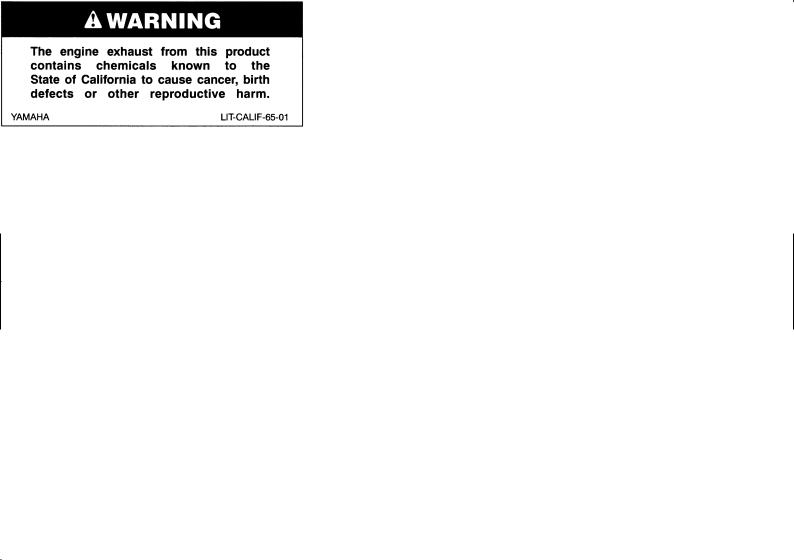
EAU03438

Congratulations on your purchase of the Yamaha FZS1000/FZS1000S. This model is the result of Yamaha’s vast experience in the production of fine sporting, touring, and pacesetting racing machines. It represents the high degree of craftsmanship and reliability that have made Yamaha a leader in these fields.
This manual will give you an understanding of the operation, inspection, and basic maintenance of this motorcycle. If you have any questions concerning the operation or maintenance of your motorcycle, please consult a Yamaha dealer.
The design and manufacture of this Yamaha motorcycle fully comply with the emissions standards for clean air applicable at the date of manufacture. Yamaha has met these standards without reducing the performance or economy of operation of the motorcycle. To maintain these high standards, it is important that you and your Yamaha dealer pay close attention to the recommended maintenance schedules and operating instructions contained within this manual.
|
IMPORTANT MANUAL INFORMATION |
EAU00003 |
Particularly important information is distinguished in this manual by the following notations:
The Safety Alert Symbol means ATTENTION! BECOME ALERT! YOUR SAFETY IS
INVOLVED!
|
WARNING |
Failure to follow WARNING instructions could result in severe injury or death to the |
|
|
motorcycle operator, a bystander or a person inspecting or repairing the motorcycle. |
||
|
CAUTION: |
A CAUTION indicates special precautions that must be taken to avoid damage to the |
|
|
motorcycle. |
||
NOTE: A NOTE provides key information to make procedures easier or clearer.
NOTE:
●This manual should be considered a permanent part of this motorcycle and should remain with it even if the motorcycle is subsequently sold.
●Yamaha continually seeks advancements in product design and quality. Therefore, while this manual contains the most current product information available at the time of printing, there may be minor discrepancies between your motorcycle and this manual. If you have any questions concerning this manual, please consult your Yamaha dealer.
IMPORTANT MANUAL INFORMATION
EW000000
 WARNING
PLEASE READ THIS MANUAL AND THE “YOU AND YOUR MOTORCYCLE: RIDING TIPS” BOOKLET CAREFULLY AND COMPLETELY BEFORE OPERATING THIS MOTORCYCLE. DO NOT ATTEMPT TO OPERATE THIS MOTORCYCLE UNTIL YOU HAVE ATTAINED ADEQUATE KNOWLEDGE OF ITS CONTROLS AND OPERATING FEATURES AND UNTIL YOU HAVE BEEN TRAINED IN SAFE AND PROPER RIDING TECHNIQUES. REGULAR INSPECTIONS AND CAREFUL MAINTENANCE, ALONG WITH GOOD RIDING SKILLS, WILL ENSURE THAT YOU SAFELY ENJOY THE CAPABILITIES AND THE RELIABILITY OF THIS MOTORCYCLE.
IMPORTANT MANUAL INFORMATION
AFFIX DEALER
LABEL HERE
EAU04247
FZS1000R/FZS1000RC/FZS1000SR/FZS1000SRC
OWNER’S MANUAL
©2002 by Yamaha Motor Corporation, U.S.A. 1st edition, May 2002
All rights reserved.
Any reprinting or unauthorized use without the written permission of Yamaha Motor Corporation, U.S.A. is expressly prohibited.
Printed in Japan.
P/N LIT-11626-16-33

|
EAU00009 |
TABLE OF CONTENTS |
|
1 |
SAFETY INFORMATION |
1 |
|
|
2 |
DESCRIPTION |
2 |
|
|
3 |
INSTRUMENT AND CONTROL FUNCTIONS |
3 |
|
|
4 |
PRE-OPERATION CHECKS |
4 |
|
|
5 |
OPERATION AND IMPORTANT RIDING POINTS |
5 |
|
|
6 |
PERIODIC MAINTENANCE AND MINOR REPAIR |
6 |
|
|
7 |
MOTORCYCLE CARE AND STORAGE |
7 |
|
|
8 |
SPECIFICATIONS |
8 |
|
|
9 |
CONSUMER INFORMATION |
9 |
|
INDEX

SAFETY INFORMATION |
|||||
|
Safe riding ……………………………………………………………………………… |
1-1 |
||||
|
Protective apparel |
1-3 |
||||
|
1 |
|||||
|
Modifications |
|||||
|
1-3 |
|||||
|
………………………………………………………….Loading and accessories |
1-3 |
||||
|
Gasoline and exhaust gas………………………………………………………… |
1-5 |
||||
|
Location of important labels …………………………………………………….. |
1-7 |
||||
|
SAFETY INFORMATION |
EAU00014 |
MOTORCYCLES ARE SINGLE TRACK VEHICLES. THEIR SAFE USE AND OPERATION ARE DEPENDENT UPON THE USE OF PROPER RIDING TECHNIQUES AS WELL AS THE EXPERTISE OF THE OPERATOR. EVERY OPERATOR SHOULD KNOW THE FOLLOWING REQUIREMENTS
1 BEFORE RIDING THIS MOTORCYCLE. HE OR SHE SHOULD:
1.OBTAIN THOROUGH INSTRUCTIONS FROM A COMPETENT SOURCE ON ALL ASPECTS OF MOTORCYCLE OPERATION.
2.OBSERVE THE WARNINGS AND MAINTENANCE REQUIREMENTS IN THE OWNER’S MANUAL.
3.OBTAIN QUALIFIED TRAINING IN SAFE AND PROPER RIDING TECHNIQUES.
4.OBTAIN PROFESSIONAL TECHNICAL SERVICE AS INDICATED BY THE OWNER’S MANUAL AND/OR WHEN MADE NECESSARY BY MECHANICAL CONDITIONS.
Safe riding
1.Always make pre-operation checks. Careful checks may help prevent an accident.
2.This motorcycle is designed to carry the operator and a passenger.
3.The failure of motorists to detect and recognize motorcycles in traffic is the predominating cause of automobile/motorcycle accidents. Many accidents have been caused by an automobile driver who
did not see the motorcycle. Making yourself conspicuous appears to be very effective in reducing the chance of this type of accident.
Therefore:
a.Wear a brightly colored jacket.
b.Use extra caution when you are approaching and passing through intersections, since intersections are the most likely places for motorcycle accidents to occur.
c.Ride where other motorists can see you. Avoid riding in another motorist’s blind spot.
1-1


 SAFETY INFORMATION
4.Many accidents involve inexperienced operators. In fact, many operators who have been involved in accidents do not even have a current motorcycle license.
a.Make sure that you are qualified and that you only lend your motorcycle to other qualified operators.
b.Know your skills and limits. Staying within your limits may help you to avoid an accident.
c.We recommend that you practice riding your motorcycle where there is no traffic until you have become thoroughly familiar with the motorcycle and all of its controls.
5.Many accidents have been caused by error of the motorcycle operator. A typical error made by the operator is veering wide on a turn due to EXCESSIVE SPEED or undercornering (insufficient lean angle for the speed).
a.Always obey the speed limit and never travel faster than warranted by road and traffic conditions.
b.Always signal before turning or changing lanes. Make sure that other motorists can see you.
6.The posture of the operator and passenger is important for proper control.
a.The operator should keep both hands on the handlebar and both feet on the operator footrests
during operation to maintain control of the motorcycle.
b.The passenger should always hold onto the operator, the seat strap or grab bar, if equipped, with both hands and keep both feet on the passenger footrests.
c.Never carry a passenger unless he or she can firmly place both feet on the passenger footrests.
7.Never ride under the influence of alcohol or other drugs.
8.This motorcycle is designed for on-road use only. It is not suitable for off-road use.
1-2
![]()

 SAFETY INFORMATION
Protective apparel
|
The majority of fatalities from motorcycle accidents are the result of head injuries. The use of a safety |
|||
|
1 |
helmet is the single most critical factor in the prevention or reduction of head injuries. |
||
|
1. |
Always wear an approved helmet. |
||
|
2. |
Wear a face shield or goggles. Wind in your unprotected eyes could contribute to an impairment of vi- |
||
|
sion that could delay seeing a hazard. |
|||
|
3. |
The use of a jacket, heavy boots, trousers, gloves, etc., is effective in preventing or reducing abra- |
||
|
sions or lacerations. |
|||
|
4. |
Never wear loose-fitting clothes, otherwise they could catch on the control levers, footrests, or wheels |
||
|
and cause injury or an accident. |
|||
|
5. |
Never touch the engine or exhaust system during or after operation. They become very hot and can |
||
|
cause burns. Always wear protective clothing that covers your legs, ankles, and feet. |
|||
|
6. |
A passenger should also observe the above precautions. |
Modifications
Modifications made to this motorcycle not approved by Yamaha, or the removal of original equipment, may render the motorcycle unsafe for use and may cause severe personal injury. Modifications may also make your motorcycle illegal to use.
Loading and accessories
Adding accessories or cargo to your motorcycle can adversely affect stability and handling if the weight distribution of the motorcycle is changed. To avoid the possibility of an accident, use extreme caution when adding cargo or accessories to your motorcycle. Use extra care when riding a motorcycle that has added cargo or accessories. Here are some general guidelines to follow if loading cargo or adding accessories to your motorcycle:
1-3


 SAFETY INFORMATION
Loading
The total weight of the operator, passenger, accessories and cargo must not exceed the maximum load limit of FZS1000, FZS1000S: 189 kg (417 lb) / FZS1000C, FZS1000SC: 188 kg (415 lb). When loading within this weight limit, keep the following in mind:
1.Cargo and accessory weight should be kept as low and close to the motorcycle as possible. Make sure to distribute the weight as evenly as possible on both sides of the motorcycle to minimize imbalance or instability.
2.Shifting weights can create a sudden imbalance. Make sure that accessories and cargo are securely attached to the motorcycle before riding. Check accessory mounts and cargo restraints frequently.
3.Never attach any large or heavy items to the handlebar, front fork, or front fender. These items, including such items as sleeping bags, duffel bags, or tents, can create unstable handling or a slow steering response.
Accessories
Genuine Yamaha accessories have been specifically designed for use on this motorcycle. Since Yamaha cannot test all other accessories that may be available, you must personally be responsible for the proper selection, installation and use of non-Yamaha accessories. Use extreme caution when selecting and installing any accessories.
Keep the following guidelines in mind, as well as those provided under “Loading” when mounting accessories.
1.Never install accessories or carry cargo that would impair the performance of your motorcycle. Carefully inspect the accessory before using it to make sure that it does not in any way reduce ground clearance or cornering clearance, limit suspension travel, steering travel or control operation, or obscure lights or reflectors.
1-4


 SAFETY INFORMATION
a.Accessories fitted to the handlebar or the front fork area can create instability due to improper weight distribution or aerodynamic changes. If accessories are added to the handlebar or front
fork area, they must be as lightweight as possible and should be kept to a minimum.
1 b. Bulky or large accessories may seriously affect the stability of the motorcycle due to aerodynamic effects. Wind may attempt to lift the motorcycle, or the motorcycle may become unstable in cross winds. These accessories may also cause instability when passing or being passed by large vehicles.
c.Certain accessories can displace the operator from his or her normal riding position. This improper position limits the freedom of movement of the operator and may limit control ability, therefore, such accessories are not recommended.
2.Use caution when adding electrical accessories. If electrical accessories exceed the capacity of the motorcycle’s electrical system, an electric failure could result, which could cause a dangerous loss of lights or engine power.
Gasoline and exhaust gas
1.GASOLINE IS HIGHLY FLAMMABLE:
a.Always turn the engine off when refueling.
b.Take care not to spill any gasoline on the engine or exhaust system when refueling.
c.Never refuel while smoking or in the vicinity of an open flame.
2.Never start the engine or let it run for any length of time in a closed area. The exhaust fumes are poisonous and may cause loss of consciousness and death within a short time. Always operate your motorcycle in an area that has adequate ventilation.
3.Always turn the engine off before leaving the motorcycle unattended and remove the key from the main switch. When parking the motorcycle, note the following:
1-5


 SAFETY INFORMATION
a.The engine and exhaust system may be hot, therefore, park the motorcycle in a place where pedestrians or children are not likely to touch these hot areas.
b.Do not park the motorcycle on a slope or soft ground, otherwise it may fall over.
c. Do not park the motorcycle near a flammable source (e.g., a kerosene heater, or near an open 1 flame), otherwise it could catch fire.
4.When transporting the motorcycle in another vehicle, make sure that it is kept upright. If the motorcycle should lean over, gasoline may leak out of the carburetor or fuel tank.
5.If you should swallow any gasoline, inhale a lot of gasoline vapor, or allow gasoline to get into your eyes, see your doctor immediately. If any gasoline spills on your skin or clothing, immediately wash the affected area with soap and water and change your clothes.
6
1-6


 SAFETY INFORMATION
EAU02977
Location of important labels
Please read the following important labels carefully before operating this motorcycle.
1
1-7

|
SAFETY INFORMATION |
||
|
1 |
5 California only |
|
|
CAUTION |
||
|
Cleaning with alkaline or |
1 |
|
|
acid cleaner, gasoline or |
solvent will damage windshield.
Use neutral detergent.
5JW-00 (5JW-2835Y-00)
2
6
1-8

DESCRIPTION |
|
|
Left view ………………………………………………………………………………… |
2-1 |
|
Right view………………………………………………………………………………. |
2-2 |
|
Controls and instruments …………………………………………………………. |
2-3 |
2

Left view
2
|
1. Front fork compression damping |
8. Seat lock/helmet holder |
(page 3-11) |
|
|
force adjusting screw |
(page 3-14) |
9. Shock absorber assembly |
|
|
2. Front fork rebound damping force |
compression damping force |
||
|
adjusting screw |
(page 3-13) |
adjusting screw |
(page 3-16) |
|
3. Front fork spring preload adjusting |
10. Shock absorber assembly spring |
||
|
bolt |
(page 3-13) |
preload adjusting ring |
(page 3-15) |
|
4. Air filter element |
(page 6-19) |
11. Shock absorber assembly rebound |
|
|
5. Fuses |
(page 6-38) |
damping force adjusting knob |
(page 3-15) |
|
6. Storage compartment |
(page 3-12) |
12. Shift pedal |
(page 3-7) |
|
7. Grab bar |
2-1

DESCRIPTION
Right view
2
|
13. Owner’s tool kit |
(page 6-1) |
18. Engine oil filter cartridge |
(page 6-13) |
|
14. Rear brake fluid reservoir |
(page 6-30) |
19. Engine oil level check window |
(page 6-12) |
|
15. Battery |
(page 6-37) |
20. Brake pedal |
(page 3-8) |
|
16. Front brake fluid reservoir |
(page 6-29) |
21. Coolant reservoir |
(page 6-15) |
|
17. Radiator cap |
(page 6-17) |
2-2

DESCRIPTION
Controls and instruments
2
|
1. Clutch lever |
(page 3-7) |
6. Tachometer unit |
(page 3-4) |
|
2. Left handlebar switches |
(page 3-6) |
7. Fuel gauge |
(page 3-5) |
|
3. Starter (choke) lever |
(page 3-10) |
8. Right handlebar switches |
(page 3-6) |
|
4. Speedometer unit |
(page 3-3) |
9. Brake lever |
(page 3-7) |
|
5. Main switch/steering lock |
(page 3-1) |
10. Throttle grip |
(page 6-22) |
2-3
![]()
INSTRUMENT AND CONTROL FUNCTIONS
|
…………………………………………………………Main switch/steering lock |
3-1 |
|||
|
Indicator and warning lights ……………………………………………………. |
3-2 |
|||
|
Speedometer unit …………………………………………………………………… |
3-3 |
|||
|
Tachometer unit ……………………………………………………………………… |
3-4 |
|||
|
Self-diagnosis devices …………………………………………………………….. |
3-5 |
|||
|
Fuel gauge |
3-5 |
|||
|
3 |
||||
|
Handlebar switches |
3-6 |
|||
|
……………………………………………………………………………Clutch lever |
3-7 |
|||
|
Shift pedal …………………………………………………………………………….. |
3-7 |
|||
|
Brake lever ……………………………………………………………………………. |
3-7 |
|||
|
Brake pedal …………………………………………………………………………… |
3-8 |
|||
|
Fuel tank cap …………………………………………………………………………. |
3-8 |
|||
|
Fuel ……………………………………………………………………………………… |
3-9 |
|||
|
Starter (choke) lever ……………………………………………………………… |
3-10 |
|||
|
Seat ……………………………………………………………………………………. |
3-11 |
|||
|
Helmet holder ………………………………………………………………………. |
3-11 |
|||
|
Storage compartment …………………………………………………………… |
3-12 |
|||
|
Adjusting the front fork ………………………………………………………….. |
3-12 |
|||
|
Adjusting the shock absorber assembly …………………………………… |
3-14 |
|||
|
EXUP system ………………………………………………………………………. |
3-17 |
|||
|
Sidestand ……………………………………………………………………………. |
3-17 |
|||
|
Ignition circuit cut-off system ………………………………………………….. |
3-18 |
|||
|
INSTRUMENT AND CONTROL FUNCTIONS |
EAU00027 |
3
1. Push.
2. Turn.
Main switch/steering lock
The main switch/steering lock controls the ignition and lighting systems, and is used to lock the steering. The various positions are described below.
EAU00032
ON
All electrical systems are supplied with power, and the headlight, meter lighting, taillight and position lights come on, and the engine can be started. The key cannot be removed.
EAU00038
OFF
All electrical systems are off. The key can be removed.
LOCK
The steering is locked, and all electrical systems are off. The key can be removed.
To lock the steering
1.Turn the handlebars all the way to the left.
2.Push the key in from the “OFF” position, and then turn it to “LOCK” while still pushing it.
3.Remove the key.
To unlock the steering
Push the key in, and then turn it to “OFF” while still pushing it.
EW000016
 WARNING
_
Never turn the key to “OFF” or “LOCK” while the motorcycle is moving, otherwise the electrical systems will be switched off, which may result in loss of control or an accident. Make sure that the motorcycle is stopped before turning the key to “OFF” or “LOCK”.
_
3-1
INSTRUMENT AND CONTROL FUNCTIONS
1.Left turn signal indicator light “  ”
”
2.Neutral indicator light “  ”
”
3.High beam indicator light “ ”
”
4.Oil level warning light “ 

 ”
”
5.Right turn signal indicator light “  ”
”
6.Coolant temperature warning light “  ”
”
7.Fuel level warning light “  ”
”
EAU03034
Indicator and warning lights
EAU04121
Turn signal indicator lights
“  ” and “
 ”
”
The corresponding indicator light flashes when the turn signal switch is pushed to the left or right.
EAU00063
High beam indicator light “ ”
”
This indicator light comes on when the high beam of the headlight is switched on.
EAU04877
Oil level warning light “ 

 ”
”
This warning light comes on when the engine oil level is low.
The electrical circuit of the warning light can be checked by turning the key to “ON”.
If the warning light does not come on for a few seconds, then go off, have a Yamaha dealer check the electrical circuit.
NOTE:
Even if the oil level is sufficient, the warning light may flicker when riding on a slope or during sudden acceleration or deceleration, but this is not a malfunction.
EAU04881
Coolant temperature warning light
“  ”
”
This warning light comes on when the engine overheats. When this occurs, stop the engine immediately and allow the engine to cool.
The electrical circuit of the warning light
can be checked by turning the key to 3 “ON”.
If the warning light does not come on for a few seconds, then go off, have a Yamaha dealer check the electrical circuit.
EC000002
CAUTION:
_
Do not operate the engine if it is overheated.
_
EAU00061
Neutral indicator light “  ”
”
This indicator light comes on when the transmission is in the neutral position.
3-2
INSTRUMENT AND CONTROL FUNCTIONS
3
1.Left turn signal indicator light “  ”
”
2.Neutral indicator light “  ”
”
3.High beam indicator light “ ”
”
4.Oil level warning light “ 

 ”
”
5.Right turn signal indicator light “  ”
”
6.Coolant temperature warning light “  ”
”
7.Fuel level warning light “  ”
”
EAU04878
Fuel level warning light “  ”
”
This warning light comes on when the fuel level drops below approximately 4 L (0.9 Imp gal, 1.1 US gal). When this occurs, refuel as soon as possible.
The electrical circuit of the warning light can be checked by turning the key to “ON”.
If the warning light does not come on for a few seconds, then go off, have a Yamaha dealer check the electrical circuit.
1.Speedometer
2.Odometer/tripmeter
3.“SELECT” button
4.“RESET” button
EAU04289
Speedometer unit
The speedometer unit is equipped with the following:
●an odometer
●two tripmeters
When set to “ODO”, the motorcycle’s total mileage is indicated.
When set to “TRIP 1” or “TRIP 2”, the motorcycle’s mileage since the tripmeter was last reset is indicated. The tripmeters can be used together with the fuel gauge to estimate the distance that can be traveled on a full tank of fuel.
This information will enable you to plan future fuel stops.
To set a mode
Push the “SELECT” button to change between the odometer mode “ODO”, and the tripmeter modes “TRIP 1” and “TRIP 2” in the following order:
ODO → TRIP 1 → TRIP 2 → ODO
To reset a meter
To reset either tripmeter 1 or 2 to 0.0, select either by pushing the “SELECT” button, and then push the “RESET” button for at least one second.
3-3
INSTRUMENT AND CONTROL FUNCTIONS
1.Tachometer
2.Tachometer red zone
3.Clock
EAU03954
Tachometer unit
The electric tachometer allows the rider to monitor the engine speed and keep it within the ideal power range.
EC000003
CAUTION:
Do not operate the engine in the tachometer red zone.
Red zone: 11,500 r/min and above
This tachometer unit is equipped with a clock.
To set the clock:
1.Push both the “SELECT” and “RESET” buttons for at least two seconds.
2.When the hour digits start flashing,
push the “RESET” button to set the hours.
3. Push the “SELECT” button to 3 change the minutes.
4.When the minute digits start flashing, push the “RESET” button to set the minutes.
5.Push the “SELECT” button to start the clock.
NOTE:
After setting the clock, be sure to push the “SELECT” button before turning the key to “OFF”, otherwise the clock will not be set.
3-4
INSTRUMENT AND CONTROL FUNCTIONS
EAU04290
Self-diagnosis devices
This model is equipped with a self-di- agnosis device for the following electrical circuits:
● throttle position sensor ● speed sensor
3
● EXUP system ● overturn switch
If any of those circuits are defective, the tachometer will repeatedly display the following error code:
|
0 r/min for |
Circuit-specific |
Current |
|
|
number of r/min |
engine |
||
|
3 seconds |
|||
|
for 2.5 seconds |
speed for |
||
|
(See the table |
3 seconds |
||
|
below.) |
Use the chart below to identify the faulty electrical circuit.
|
Specific r/min |
Faulty electrical circuit |
|
3,000 r/min |
Throttle position sensor |
|
4,000 r/min |
Speed sensor |
|
7,000 r/min |
EXUP system |
|
9,000 r/min |
Overturn switch |
If the tachometer displays such an error code, note the circuit-specific number of r/min, and then have a Yamaha dealer check the motorcycle.
EC000004
CAUTION:
When the tachometer displays an error code, the motorcycle should be checked as soon as possible in order to avoid engine damage.
1. Fuel gauge
EAU00110
Fuel gauge
The fuel gauge indicates the amount of fuel in the fuel tank. The needle moves towards “E” (Empty) as the fuel level decreases. When the needle reaches “E”, approximately 4 L (0.9 Imp gal, 1.1 US gal) of fuel remain in the fuel tank. If this occurs, refuel as soon as possible.
NOTE:
_
Do not allow the fuel tank to empty itself completely.
_
3-5

INSTRUMENT AND CONTROL FUNCTIONS
1.Dimmer switch “ /
/  ”
”
2.Turn signal switch “  /
/  ”
”
3.Horn switch “  ”
”
EAU00118
Handlebar switches
EAU03888
Dimmer switch “ /
/  ”
”
Set this switch to “ ” for the high beam and to “
  ” for the low beam.
EAU03889
Turn signal switch “  /
/  ”
”
To signal a right-hand turn, push this switch to “  ”. To signal a left-hand turn, push this switch to “
  ”. When released, the switch returns to the center position. To cancel the turn signal lights, push the switch in after it has returned to the center position.
EAU00129
Horn switch “  ”
”
Press this switch to sound the horn.
3
1.Engine stop switch “  /
/  ”
”
2.Start switch “  ”
”
EAU03890
Engine stop switch “  /
/  ”
”
Set this switch to “  ” before starting the engine. Set this switch to “
  ” to stop the engine in case of an emergency, such as when the motorcycle overturns or when the throttle cable is stuck.
EAU00143
Start switch “  ”
”
Push this switch to crank the engine with the starter.
EC000005
CAUTION:
_
See page 5-1 for starting instructions prior to starting the engine.
_
3-6

INSTRUMENT AND CONTROL FUNCTIONS
3
1. Clutch lever
EAU00152
Clutch lever
The clutch lever is located at the left handlebar grip. To disengage the clutch, pull the lever toward the handlebar grip. To engage the clutch, release the lever. The lever should be pulled rapidly and released slowly for smooth clutch operation.
The clutch lever is equipped with a clutch switch, which is part of the ignition circuit cut-off system. (See page 3-18 for an explanation of the ignition circuit cut-off system.)
1. Shift pedal
EAU00157
Shift pedal
The shift pedal is located on the left side of the engine and is used in combination with the clutch lever when shifting the gears of the 6-speed con- stant-mesh transmission equipped on this motorcycle.
1.Brake lever
2.Brake lever position adjusting dial
3.Arrow mark
a.Distance between brake lever and handlebar grip
EAU00161
Brake lever
The brake lever is located at the right handlebar grip. To apply the front brake, pull the lever toward the handlebar grip. The brake lever is equipped with a position adjusting dial. To adjust the distance between the brake lever and the handlebar grip, turn the adjusting dial while holding the lever pushed away from the handlebar grip. Make sure that the appropriate setting on the adjusting dial is aligned with the arrow mark on the brake lever.
3-7
INSTRUMENT AND CONTROL FUNCTIONS
1. Brake pedal
EAU00162
Brake pedal
The brake pedal is on the right side of the motorcycle. To apply the rear brake, press down on the brake pedal.
1.Fuel tank cap lock cover
2.Unlock.
EAU02935
Fuel tank cap
To open the fuel tank cap
Open the fuel tank cap lock cover, insert the key into the lock, and then turn it 1/4 turn clockwise. The lock will be released and the fuel tank cap can be opened.
2.Turn the key counterclockwise to the original position, remove it, and then close the lock cover.
NOTE:
_
The fuel tank cap cannot be closed unless the key is in the lock. In addition, the key cannot be removed if the cap is
|
not properly closed and locked. |
3 |
|||
|
_ |
||||
|
EWA00025 |
||||
|
WARNING |
||||
|
_ |
Make sure that the fuel tank cap is properly closed before riding.
_
To close the fuel tank cap
1.Push the fuel tank cap into position with the key inserted in the lock.
3-8

INSTRUMENT AND CONTROL FUNCTIONS
EAU00185
CAUTION:
Immediately wipe off spilled fuel with a clean, dry, soft cloth, since fuel may deteriorate painted surfaces or plastic parts.
3
1.Fuel tank filler tube
2.Fuel level
EAU03753
Fuel
Make sure that there is sufficient fuel in the tank. Fill the fuel tank to the bottom of the filler tube as shown.
EW000130
 WARNING
●Do not overfill the fuel tank, otherwise it may overflow when the fuel warms up and expands.
●Avoid spilling fuel on the hot engine.
EAU04265
Recommended fuel:
UNLEADED GASOLINE ONLY Fuel tank capacity:
Total amount:
21 L (4.6 Imp gal, 5.5 US gal) Reserve amount:
4 L (0.9 Imp gal, 1.1 US gal)
ECA00104
CAUTION:
_
Use only unleaded gasoline. The use of leaded gasoline will cause severe damage to internal engine parts, such as the valves and piston rings, as well as to the exhaust system.
_
3-9
![]()
INSTRUMENT AND CONTROL FUNCTIONS
|
Your Yamaha engine has been de- |
|||||
|
signed to use regular unleaded gaso- |
|||||
|
line with a pump octane number |
|||||
|
[(R+M)/2] of 86 or higher, or a research |
|||||
|
octane number of 91 or higher. If |
|||||
|
knocking (or pinging) occurs, use a |
|||||
|
gasoline of a different brand or premi- |
|||||
|
um unleaded fuel. Use of unleaded fuel |
3 |
||||
|
will extend spark plug life and reduce |
|||||
|
1. Starter (choke) lever “ |
” |
||||
|
maintenance costs. |
|||||
|
EAU03839 |
|||||
Gasohol
There are two types of gasohol: gasohol containing ethanol and that containing methanol. Gasohol containing ethanol can be used if the ethanol content does not exceed 10%. Gasohol containing methanol is not recommended by Yamaha because it can cause damage to the fuel system or vehicle performance problems.
Starter (choke) lever “ 

 ”
”
Starting a cold engine requires a richer air-fuel mixture, which is supplied by the starter (choke).
Move the lever in direction a to turn on the starter (choke).
Move the lever in direction b to turn off the starter (choke).
3-10

INSTRUMENT AND CONTROL FUNCTIONS
3
1.Seat lock
2.Unlock.
EAU03956
Seat
To remove the seat
1.Insert the key into the seat lock, and then turn it clockwise.
2.While holding the key in that position, lift the rear of the seat, and then pull the seat off.
1.Projection
2.Seat holder
To install the seat
1.Insert the projection on the front of the seat into the seat holder as shown.
2.Push the rear of the seat down to lock it in place.
3.Remove the key.
NOTE:
Make sure that the seat is properly secured before riding.
1.Helmet holder
2.Unlock.
EAU04291
Helmet holder
To open the helmet holder, insert the key into the seat lock, and then turn the key as shown.
To lock the helmet holder, turn the key to the original position, and then remove it.
EW000030
 WARNING
_
Never ride with a helmet attached to the helmet holder, since the helmet may hit objects, causing loss of control and possibly an accident.
_
3-11

INSTRUMENT AND CONTROL FUNCTIONS
When storing the owner’s manual or other documents in the storage compartment, be sure to wrap them in a plastic bag so that they will not get wet. When washing the motorcycle, be careful not to let any water enter the storage compartment.
1. Storage compartment
EAU04101
Storage compartment
The storage compartment is located under the seat. (See page 3-11 for seat removal and installation procedures.)
EWA00005
 WARNING
●Do not exceed the load limit of 3 kg (7 lb) for the storage compartment.
●Do not exceed the maximum load of FZS1000, FZS1000S: 189 kg (417 lb) / FZS1000C, FZS1000SC: 188 kg (415 lb) for the vehicle.
EAU04293
Adjusting the front fork
This front fork is equipped with spring preload adjusting bolts, rebound damping force adjusting screws and compression damping force adjusting screws.
|
EW000035 |
3 |
|||
|
WARNING |
||||
|
_ |
Always adjust both fork legs equally, otherwise poor handling and loss of stability may result.
_
3-12

INSTRUMENT AND CONTROL FUNCTIONS
3
1. Spring preload adjusting bolt
Spring preload
To increase the spring preload and thereby harden the suspension, turn the adjusting bolt on each fork leg in direction a. To decrease the spring preload and thereby soften the suspension, turn the adjusting bolt on each fork leg in direction b.
1.Current setting
2.Front fork cap bolt
NOTE:
Align the appropriate groove on the adjusting mechanism with the top of the front fork cap bolt.
|
Setting |
|
|
Minimum (soft) |
5* |
|
Standard |
2 |
|
Maximum (hard) |
1 |
* fully turned out position
1. Rebound damping force adjusting screw
Rebound damping force
To increase the rebound damping force and thereby harden the rebound damping, turn the adjusting screw on each fork leg in direction a. To decrease the rebound damping force and thereby soften the rebound damping, turn the adjusting screw on each fork leg in direction b.
|
Minimum (soft) |
17 clicks in direction b* |
|
Standard |
7 clicks in direction b* |
|
Maximum (hard) |
1 click in direction b* |
* With the adjusting screw fully turned in direction a
3-13

INSTRUMENT AND CONTROL FUNCTIONS
1. Compression damping force adjusting screw
Compression damping force
To increase the compression damping force and thereby harden the compression damping, turn the adjusting screw on each fork leg in direction a. To decrease the compression damping force and thereby soften the compression damping, turn the adjusting screw on each fork leg in direction b.
|
Minimum (soft) |
21 clicks in direction b* |
|
Standard |
6 clicks in direction b* |
|
Maximum (hard) |
1 click in direction b* |
* With the adjusting screw fully turned in direction a
EC000015
CAUTION:
Never attempt to turn an adjusting mechanism beyond the maximum or minimum settings.
NOTE:
Although the total number of clicks of a damping force adjusting mechanism may not exactly match the above specifications due to small differences in production, the actual number of clicks always represents the entire adjusting range. To obtain a precise adjustment, it would be advisable to check the number of clicks of each damping force adjusting mechanism and to modify the specifications as necessary.
|
EAU04295* |
||||
|
Adjusting the shock absorber |
||||
|
assembly |
||||
|
This shock absorber assembly is |
||||
|
equipped with a spring preload adjust- |
||||
|
ing ring, a rebound damping force ad- |
||||
|
justing knob and a compression |
||||
|
damping force adjusting screw. |
3 |
|||
|
EC000015 |
||||
|
CAUTION: |
||||
|
_ |
||||
|
Never attempt to turn an adjusting |
||||
|
mechanism beyond the maximum |
||||
|
or minimum settings. |
_
3-14

INSTRUMENT AND CONTROL FUNCTIONS
3
1.Spring preload adjusting ring
2.Special wrench
3.Position indicator
Spring preload
To increase the spring preload and thereby harden the suspension, turn the adjusting ring in direction a. To decrease the spring preload and thereby soften the suspension, turn the adjusting ring in direction b.
NOTE:
●Align the appropriate notch in the adjusting ring with the position indicator on the shock absorber.
●Use the special wrench included in the owner’s tool kit to make the adjustment.
|
Setting |
|
|
Minimum (soft) |
1 |
|
Standard |
6 |
|
Maximum (hard) |
11 |
1. Rebound damping force adjusting knob
Rebound damping force
To increase the rebound damping force and thereby harden the rebound damping, turn the adjusting knob in direction a. To decrease the rebound damping force and thereby soften the rebound damping, turn the adjusting knob in direction b.
|
Minimum (soft) |
20 clicks in direction b* |
|
Standard |
10 clicks in direction b* |
|
Maximum (hard) |
3 clicks in direction b* |
* With the adjusting knob fully turned in direction a
3-15

INSTRUMENT AND CONTROL FUNCTIONS
1. Compression damping force adjusting screw
Compression damping force
To increase the compression damping force and thereby harden the compression damping, turn the adjusting screw in direction a. To decrease the compression damping force and thereby soften the compression damping, turn the adjusting screw in direction b.
|
Minimum (soft) |
1 click in direction a* |
|
Standard |
7 clicks in direction a* |
|
Maximum (hard) |
12 clicks in direction a* |
* With the adjusting screw fully turned in direction b
NOTE:
Although the total number of clicks of a damping force adjusting mechanism may not exactly match the above specifications due to small differences in production, the actual number of clicks always represents the entire adjusting range. To obtain a precise adjustment, it would be advisable to check the number of clicks of each damping force adjusting mechanism and to modify the specifications as necessary.
EAU00315
WARNING
_
This shock absorber contains high-
|
ly pressurized nitrogen gas. For |
||
|
proper handling, read and under- |
||
|
stand the following information be- |
||
|
fore handling the shock absorber. |
||
|
The manufacturer cannot be held re- |
3 |
|
|
sponsible for property damage or |
||
|
personal injury that may result from |
||
|
improper handling. |
●Do not tamper with or attempt to open the gas cylinder.
●Do not subject the shock absorber to an open flame or other high heat sources, otherwise it may explode due to excessive gas pressure.
●Do not deform or damage the gas cylinder in any way, as this will result in poor damping performance.
●Always have a Yamaha dealer service the shock absorber.
_
3-16

INSTRUMENT AND CONTROL FUNCTIONS
EAU01571
EXUP system
This motorcycle is equipped with Yamaha’s EXUP (EXhaust Ultimate Power valve) system. This system boosts engine power by means of a valve that regulates the diameter of the
3
exhaust pipe. The EXUP system valve is constantly adjusted in accordance with the engine speed by a computercontrolled servomotor.
EC000027
CAUTION:
●The EXUP system has been set and extensively tested at the Yamaha factory. Changing these settings without sufficient technical knowledge may result in poor performance of or damage to the engine.
●If the EXUP system does not operate, have a Yamaha dealer check it.
EAU00330
Sidestand
The sidestand is located on the left side of the frame. Raise the sidestand or lower it with your foot while holding the motorcycle upright.
NOTE:
The built-in sidestand switch is part of the ignition circuit cut-off system, which cuts the ignition in certain situations. (See further down for an explanation of the ignition circuit cut-off system.)
EW000044
WARNING
_
The motorcycle must not be ridden with the sidestand down, or if the sidestand cannot be properly moved up (or does not stay up), otherwise the sidestand could contact the ground and distract the operator, resulting in a possible loss of control. Yamaha’s ignition circuit cut-off system has been designed to assist the operator in fulfilling the responsibility of raising the sidestand before starting off. Therefore, check this system regularly as described below and have a Yamaha dealer repair it if it does not function properly.
_
3-17