- Manuals
- Brands
- Yamaha Manuals
- Motorcycle
- FAZER FZS1000
- Owner’s manual
2004
-
Contents
-
Table of Contents
-
Troubleshooting
-
Bookmarks
Quick Links
OWNER’S MANUAL
FZS1000
FZS1000S
1C2-28199-EA
Related Manuals for Yamaha FZS1000
Summary of Contents for Yamaha FZS1000
-
Page 1
OWNER’S MANUAL FZS1000 FZS1000S 1C2-28199-EA… -
Page 3
Yamaha a reputation for dependability. Please take the time to read this manual thoroughly, so as to enjoy all advantages of your FZS1000/FZS1000S. The owner’s manual does not only instruct you in how to operate, inspect and maintain your motorcycle, but also in how to safeguard yourself and others from trouble and injury. -
Page 4: Important Manual Information
This manual should be considered a permanent part of this motorcycle and should remain with it even if the motorcycle is subsequently sold. Yamaha continually seeks advancements in product design and quality. Therefore, while this manual contains the most current product information available at the time of printing, there may be minor discrepancies between your motorcycle and this manual.
-
Page 5
IMPORTANT MANUAL INFORMATION EAU10200 FZS1000/FZS1000S OWNER’S MANUAL ©2004 by Yamaha Motor Co., Ltd. 1st edition, July 2004 All rights reserved. Any reprinting or unauthorized use without the written permission of Yamaha Motor Co., Ltd. is expressly prohibited. Printed in Japan. -
Page 6: Table Of Contents
TABLE OF CONTENTS SAFETY INFORMATION ….1-1 Adjusting the shock absorber Adjusting the engine idling assembly ……..3-15 speed ……..6-16 DESCRIPTION ……..2-1 EXUP system ……. 3-17 Checking the throttle cable free Left view ……….2-1 Sidestand ……..3-17 play ……….. 6-17 Right view ……..2-2 Ignition circuit cut-off system ..
-
Page 7
TABLE OF CONTENTS Checking the front fork ….6-28 Checking the steering ….6-28 Checking the wheel bearings ..6-29 Battery ……….6-29 Replacing the fuses ……6-31 Replacing a headlight bulb …6-32 Replacing a tail/brake light bulb …6-33 Replacing a turn signal light bulb ………..6-34 Replacing an auxiliary light bulb …6-34 Front wheel ……..6-35 Rear wheel ……..6-36… -
Page 8: Safety Information
SAFETY INFORMATION EAU10271 AND/OR WHEN MADE NECES- • Ride where other motorists can SARY BY MECHANICAL CONDI- see you. Avoid riding in another MOTORCYCLES SINGLE TIONS. motorist’s blind spot. TRACK VEHICLES. THEIR SAFE USE Many accidents involve inexperi- AND OPERATION ARE DEPENDENT Safe riding enced operators.
-
Page 9
Modifications made to this motorcycle other motorists can see you. the single most critical factor in the pre- not approved by Yamaha, or the re- The posture of the operator and vention or reduction of head injuries. moval of original equipment, may ren- passenger is important for proper Always wear an approved helmet. -
Page 10
Maximum load: been specifically designed for use on create instability due to improper 189 kg (417 lb) this motorcycle. Since Yamaha cannot weight distribution or aerody- test all other accessories that may be namic changes. If accessories When loading within this weight limit,… -
Page 11
SAFETY INFORMATION tor and may limit control ability, Always turn the engine off before or clothing, immediately wash the therefore, such accessories are leaving the motorcycle unattended affected area with soap and water not recommended. and remove the key from the main and change your clothes. -
Page 12: Description
DESCRIPTION EAU10410 Left view 1. Front fork compression damping force adjusting screw (page 3-13) 11.Shock absorber assembly spring preload adjusting ring (page 3-15) 2. Front fork rebound damping force adjusting screw (page 3-13) 12.Shock absorber assembly rebound damping force adjusting knob (page 3-15) 3.
-
Page 13: Right View
DESCRIPTION EAU10420 Right view 1. Owner’s tool kit (page 6-1) 2. Rear brake fluid reservoir (page 6-22) 3. Battery (page 6-29) 4. Front brake fluid reservoir (page 6-22) 5. Radiator cap (page 6-11) 6. Engine oil filter cartridge (page 6-8) 7.
-
Page 14: Controls And Instruments
DESCRIPTION EAU10430 Controls and instruments 1. Clutch lever (page 3-7) 2. Left handlebar switches (page 3-6) 3. Starter (choke) lever (page 3-11) 4. Speedometer unit (page 3-3) 5. Main switch/steering lock (page 3-1) 6. Tachometer unit (page 3-4) 7. Fuel gauge (page 3-5) 8.
-
Page 15: Instrument And Control Functions
INSTRUMENT AND CONTROL FUNCTIONS EAU10460 EAU10660 To unlock the steering Main switch/steering lock All electrical systems are off. The key can be removed. EAU10680 LOCK The steering is locked, and all electrical systems are off. The key can be re- moved.
-
Page 16: Indicator And Warning Lights
3. High beam indicator light “ ” for a few seconds, then go off, have a 4. Oil level warning light “ ” Yamaha dealer check the electrical cir- 5. Right turn signal indicator light “ ” cuit. 6. Coolant temperature warning light “…
-
Page 17: Speedometer Unit
“ON”. If the warning light does not come on for a few seconds, then go off, have a 1. Speedometer Yamaha dealer check the electrical cir- 2. Odometer/tripmeters cuit. 3. “SELECT” button 4. “RESET” button…
-
Page 18: Tachometer Unit
INSTRUMENT AND CONTROL FUNCTIONS be traveled on a full tank of fuel. This in- EAU11891 To set the clock Tachometer unit formation will enable you to plan future 1. Push both the “SELECT” and “RE- fuel stops. SET” buttons for at least two sec- onds.
-
Page 19: Self-Diagnosis Devices
EAU12110 Self-diagnosis devices Fuel gauge code, note the circuit-specific number This model is equipped with a self-diag- of r/min, and then have a Yamaha deal- nosis device for the following electrical er check the vehicle. circuits: ECA10040 throttle position sensor…
-
Page 20: Anti-Theft Alarm (Optional)
EAU12343 Right Anti-theft alarm (optional) Handlebar switches This model can be equipped with an Left optional anti-theft alarm by a Yamaha dealer. Contact a Yamaha dealer for more information. 1. Engine stop switch “ ” 2. Start switch “ ”…
-
Page 21: Clutch Lever
INSTRUMENT AND CONTROL FUNCTIONS position. To cancel the turn signal EAU12731 EAU12820 Hazard switch “ ” Clutch lever lights, push the switch in after it has re- With the key in the “ON” or “ ” posi- turned to the center position. tion, use this switch to turn on the haz- ard light (simultaneous flashing of all EAU12500…
-
Page 22: Shift Pedal
INSTRUMENT AND CONTROL FUNCTIONS EAU12870 EAU12930 EAU12941 Shift pedal Brake lever Brake pedal The brake lever is located at the right handlebar grip. To apply the front brake, pull the lever toward the handle- bar grip. 1. Shift pedal 1. Brake pedal The shift pedal is located on the left The brake pedal is on the right side of side of the engine and is used in com-…
-
Page 23: Fuel Tank Cap
INSTRUMENT AND CONTROL FUNCTIONS EAU13070 EAU13210 Fuel tank cap NOTE: Fuel The fuel tank cap cannot be closed un- less the key is in the lock. In addition, the key cannot be removed if the cap is not properly closed and locked. EWA11090 WARNING Make sure that the fuel tank cap is…
-
Page 24: Fuel Tank Breather Hose
Your Yamaha engine has been de- signed to use regular unleaded gaso- line with a research octane number of 91 or higher. If knocking (or pinging) oc-…
-
Page 25: Catalytic Converter
INSTRUMENT AND CONTROL FUNCTIONS EAU13440 EAU13590 EAU13940 Catalytic converter Starter (choke) lever “ ” Seat This vehicle is equipped with a catalytic converter in the muffler. To remove the seat 1. Insert the key into the seat lock, EWA10860 WARNING and then turn it clockwise.
-
Page 26: Helmet Holder
This storage compartment is designed lock it in place. To open the helmet holder, insert the to hold an optional genuine Yamaha U- 3. Remove the key. key into the seat lock, and then turn the LOCK. (Other locks may not fit.) When NOTE: key as shown.
-
Page 27: Adjusting The Front Fork
1. U-LOCK bar (optional) ly, otherwise poor handling and loss 2. Strap of stability may result. 3. Yamaha U-LOCK (optional) When storing the owner’s manual or Spring preload other documents in the storage com- partment, be sure to wrap them in a plastic bag so that they will not get wet.
-
Page 28: Rebound/Compression Damping Force
INSTRUMENT AND CONTROL FUNCTIONS Rebound damping force Compression damping force ECA10100 CAUTION: Never attempt to turn an adjusting mechanism beyond the maximum or minimum settings. NOTE: Although the total number of clicks of a damping force adjusting mechanism may not exactly match the above spec- ifications due to small differences in 1.
-
Page 29: Adjusting The Shock Absorber Assembly
INSTRUMENT AND CONTROL FUNCTIONS EAU15041 To increase the spring preload and Rebound damping force Adjusting the shock absorber thereby harden the suspension, turn assembly the adjusting ring in direction (a). To de- This shock absorber assembly is crease the spring preload and thereby equipped with a spring preload adjust- soften the suspension, turn the adjust- ing ring, a rebound damping force ad-…
-
Page 30
To obtain a precise adjustment, formance. it would be advisable to check the num- Always have a Yamaha dealer ber of clicks of each damping force ad- service the shock absorber. 1. Compression damping force adjusting screw justing mechanism and to modify the specifications as necessary. -
Page 31: Exup System
INSTRUMENT AND CONTROL FUNCTIONS EAU15280 EAU15300 below and have a Yamaha dealer re- EXUP system Sidestand pair it if it does not function proper- This model is equipped with Yamaha’s The sidestand is located on the left side EXUP (EXhaust Ultimate Power valve) of the frame.
-
Page 32: Ignition Circuit Cut-Off System
Periodically check the operation of the ignition circuit cut-off system according to the following procedure. EWA10260 WARNING The vehicle must be placed on the centerstand during this in- spection. If a malfunction is noted, have a Yamaha dealer check the sys- tem before riding. 3-18…
-
Page 33
5. Push the start switch. Does the engine start? The neutral switch may be defective. The motorcycle should not be ridden until checked by a Yamaha dealer. With the engine still running: 6. Move the sidestand up. 7. Keep the clutch lever pulled. -
Page 34: Pre-Operation Checks
PRE-OPERATION CHECKS EAU15591 The condition of a vehicle is the owner’s responsibility. Vital components can start to deteriorate quickly and unexpectedly, even if the vehicle remains unused (for example, as a result of exposure to the elements). Any damage, fluid leakage or loss of tire air pressure could have serious consequences.
-
Page 35: Pre-Operation Check List
• If necessary, add recommended coolant to specified level. 6-11 • Check cooling system for leakage. • Check operation. • If soft or spongy, have Yamaha dealer bleed hydraulic system. • Check brake pads for wear. Front brake • Replace if necessary.
-
Page 36
• Make sure that operation is smooth. • Check cable free play. Throttle grip 6-17, 6-26 • If necessary, have Yamaha dealer adjust cable free play and lubricate cable and grip housing. • Make sure that operation is smooth. Control cables 6-25 •… -
Page 37: Operation And Important Riding Points
EWA10290 Yamaha dealer check the electrical cir- WARNING Never start the engine or oper- cuit. ate it in a closed area for any Before…
-
Page 38
Yamaha dealer check the with sufficient engine oil, have a electrical circuit. Yamaha dealer check the elec- trical circuit. -
Page 39: Starting A Warm Engine
OPERATION AND IMPORTANT RIDING POINTS EAU16640 EAU16671 ECA10260 Starting a warm engine Shifting CAUTION: Follow the same procedure as for start- Even with the transmission in ing a cold engine with the exception the neutral position, do not that the starter (choke) is not required coast for long periods of time when the engine is warm.
-
Page 40: Tips For Reducing Fuel Consumption
(e.g., in traffic jams, at traffic period, immediately have a lights or at railroad crossings). Yamaha dealer check the vehi- EAU17091 cle. 0–1000 km (0–600 mi) Avoid prolonged operation above 5800 r/min.
-
Page 41: Parking
OPERATION AND IMPORTANT RIDING POINTS EAU17212 Parking When parking, stop the engine, and then remove the key from the main switch. EWA10310 WARNING Since the engine and exhaust system can become very hot, park in a place where pedestri- ans or children are not likely to touch them.
-
Page 42: Periodic Maintenance And Minor Repair
Yamaha dealer certain maintenance work correctly. do it for you. NOTE: If you do not have the tools or experi- ence required for a particular job, have a Yamaha dealer perform it for you.
-
Page 43: Periodic Maintenance And Lubrication Chart
The annual checks must be performed every year, except if a kilometer-based maintenance is performed in- stead. From 50000 km, repeat the maintenance intervals starting from 10000 km. Items marked with an asterisk should be performed by a Yamaha dealer as they require special tools, data and technical skills. ODOMETER READING (× 1000 km)
-
Page 44
PERIODIC MAINTENANCE AND MINOR REPAIR ODOMETER READING (× 1000 km) ANNUAL ITEM CHECK OR MAINTENANCE JOB CHECK √ √ √ √ √ • Check for cracks or damage. 9 * Brake hoses • Replace. Every 4 years √ √ √ √… -
Page 45
PERIODIC MAINTENANCE AND MINOR REPAIR ODOMETER READING (× 1000 km) ANNUAL ITEM CHECK OR MAINTENANCE JOB CHECK • Check starter (choke) operation. √ √ √ √ √ √ 22 * Carburetors • Adjust engine idling speed and synchronization. • Change. √… -
Page 46
PERIODIC MAINTENANCE AND MINOR REPAIR Hydraulic brake service • Regularly check and, if necessary, correct the brake fluid level. • Every two years replace the internal components of the brake master cylinders and calipers, and change the brake fluid. • Replace the brake hoses every four years and if cracked or damaged. -
Page 47: Removing And Installing Panels
PERIODIC MAINTENANCE AND MINOR REPAIR EAU18771 Removing and installing panels The panels shown need to be removed to perform some of the maintenance jobs described in this chapter. Refer to this section each time a panel needs to be removed and installed. 1.
-
Page 48: Checking The Spark Plugs
Do not attempt to diagnose such 1. Spark plug cap problems yourself. Instead, have a 2. Remove the spark plug as shown, Yamaha dealer check the vehicle. with the spark plug wrench includ- ed in the owner’s tool kit.
-
Page 49: Engine Oil And Oil Filter Cartridge
PERIODIC MAINTENANCE AND MINOR REPAIR 3. Check each spark plug for elec- 2. Clean the surface of the spark plug EAU19890 Engine oil and oil filter trode erosion and excessive car- gasket and its mating surface, and cartridge bon or other deposits, and replace then wipe off any grime from the The engine oil level should be checked it if necessary.
-
Page 50: To Change Engine Oil
2. Oil filter cartridge NOTE: An oil filter wrench is available at a 1. Engine oil filler cap Yamaha dealer. 2. Engine oil level check window 1. Engine oil drain bolt 3. Maximum level mark 5. Apply a thin coat of engine oil to 4.
-
Page 51
PERIODIC MAINTENANCE AND MINOR REPAIR Recommended engine oil: See page 8-1. Oil quantity: Without oil filter cartridge replace- ment: 2.80 L (2.96 US qt) (2.46 Imp.qt) With oil filter cartridge replacement: 3.00 L (3.17 US qt) (2.64 Imp.qt) ECA11620 CAUTION: 1. -
Page 52: Coolant
If the oil level warning light flickers EAU20101 or remains on, immediately turn the To check the coolant level engine off and have a Yamaha dealer 1. Place the vehicle on the center- 1. Coolant reservoir check the vehicle. stand.
-
Page 53
2. Remove panels A and B. (See If water has been added to the page 6-6.) coolant, have a Yamaha dealer 3. Place a container under the engine check the antifreeze content of to collect the used coolant. -
Page 54
If ant as soon as possible, other- 7 Nm (0.7 m·kgf, 5 ft·lbf) coolant is leaking, have a Yamaha wise the engine may not be sufficiently cooled and the cool- dealer check the cooling system. -
Page 55: Cleaning The Air Filter Element
PERIODIC MAINTENANCE AND MINOR REPAIR EAU20681 Do not tilt or pull the fuel tank Cleaning the air filter element too much, otherwise the fuel The air filter element should be cleaned hoses may come loose, which at the intervals specified in the periodic could cause fuel leakage.
-
Page 56
Before installing the fuel tank, make sure that the fuel hoses are not damaged. If any fuel hose is damaged, do not start the engine but have a Yamaha dealer replace the hose, other- wise fuel may leak. Make sure that the fuel hoses are properly connected and 1. -
Page 57: Adjusting The Carburetors
Therefore, most carbu- checked and, if necessary, adjusted as retor adjustments should be left to a follows at the intervals specified in the Yamaha dealer, who has the neces- periodic maintenance and lubrication sary professional knowledge and expe- chart.
-
Page 58: Checking The Throttle Cable Free Play
Yamaha dealer at the intervals specified in the periodic Tire air pressure maintenance and lubrication chart. The tire air pressure should be checked and, if necessary, adjusted before each ride.
-
Page 59
189 kg (417 lb) glass fragments in it, or if the sidewall is weight evenly on both sides. * Total weight of rider, passenger, car- cracked, have a Yamaha dealer re- Adjust the suspension and tire go and accessories place the tire immediately. -
Page 60
PERIODIC MAINTENANCE AND MINOR REPAIR EWA10470 This motorcycle is equipped with cast Front tire: WARNING wheels and tubeless tires with valves. Size: Have a Yamaha dealer replace EWA10480 120/70 ZR17M/C (58W) WARNING Manufacturer/model: excessively worn tires. Besides METZELER/MEZ4Y FRONT being illegal, operating the vehi-… -
Page 61: Cast Wheels
If any damage is found, have a Yamaha dealer re- place the wheel. Do not attempt even the smallest repair to the wheel. A deformed or cracked 1.
-
Page 62: Adjusting The Rear Brake Light Switch
Front brake clutch does not operate correctly, have a Yamaha dealer check the internal clutch mechanism. 1. Rear brake light switch 2. Rear brake light switch adjusting nut 1. Brake pad wear indicator groove…
-
Page 63: Checking The Brake Fluid Level
When checking the fluid level, point that the wear indicator groove has make sure that the top of the brake almost disappeared, have a Yamaha fluid reservoir is level. dealer replace the brake pads as a set. Use only the recommended quality 1.
-
Page 64: Changing The Brake Fluid
EAU22760 Changing the brake fluid Drive chain slack ter the brake fluid reservoir when Have a Yamaha dealer change the The drive chain slack should be refilling. Water will significantly brake fluid at the intervals specified in checked before each ride and adjusted…
-
Page 65
PERIODIC MAINTENANCE AND MINOR REPAIR Drive chain slack: Tightening torque: 40.0–50.0 mm (1.57–1.97 in) Axle nut: 150 Nm (15.0 m·kgf, 108 ft·lbf) 5. If the drive chain slack is incorrect, adjust it as follows. EAU22940 To adjust the drive chain slack 1. -
Page 66: Lubricating The Drive Chain
Service the drive chain as ed if necessary. If a cable is damaged follows. or does not move smoothly, have a ECA10581 Yamaha dealer check or replace it. CAUTION: The drive chain must be lubricated Recommended lubricant: Engine oil after washing the motorcycle and riding in the rain.
-
Page 67: Checking And Lubricating The Throttle Grip And Cable
PERIODIC MAINTENANCE AND MINOR REPAIR EAU23110 EAU23131 EAU23140 Checking and lubricating the Checking and lubricating the Checking and lubricating the throttle grip and cable brake and shift pedals brake and clutch levers The operation of the throttle grip should be checked before each ride. In addi- tion, the cable should be lubricated or replaced at the intervals specified in the periodic maintenance chart.
-
Page 68: Checking And Lubricating The Centerstand And Sidestand
EWA10740 WARNING If the centerstand or sidestand does not move up and down smoothly, have a Yamaha dealer check or re- pair it. Recommended lubricant: Lithium-soap-based grease (all-pur- pose grease) 6-27…
-
Page 69: Checking The Front Fork
Securely support the vehicle so that fork does not operate smoothly, damage and excessive oil leakage. there is no danger of it falling over. have a Yamaha dealer check or re- pair it. To check the operation 2. Hold the lower ends of the front 1.
-
Page 70: Checking The Wheel Bearings
If there is play in the wheel hub or if the wheel does not turn smoothly, have a Yamaha dealer check the wheel bearings. 1. Negative battery terminal 2. Positive battery terminal…
-
Page 71
Storing a discharged battery can cause permanent To charge the battery battery damage. Have a Yamaha dealer charge the bat- To charge a sealed-type (MF) tery as soon as possible if it seems to battery, a special (constant-volt- have discharged. Keep in mind that the age) battery charger is required. -
Page 72: Replacing The Fuses
EAU23622 2. Remove the blown fuse, and then 4. If the fuse immediately blows Replacing the fuses install a new fuse of the specified again, have a Yamaha dealer amperage. check the electrical system. Specified fuses: Main fuse: 30.0 A Headlight fuse: 20.0 A…
-
Page 73: Replacing A Headlight Bulb
PERIODIC MAINTENANCE AND MINOR REPAIR EAU23900 Headlight bulb Replacing a headlight bulb Do not touch the glass part of This model is equipped with quartz bulb the headlight bulb to keep it free headlights. If a headlight bulb burns from oil, otherwise the transpar- out, replace it as follows.
-
Page 74: Replacing A Tail/Brake Light Bulb
Replacing a tail/brake light and then connect the coupler. bulb 6. Install the panel. 1. Remove the seat. (See page 7. Have a Yamaha dealer adjust the 3-11.) headlight beam if necessary. 2. Remove the tail/brake light bulb cover. 1. Tail/brake light bulb socket 4.
-
Page 75: Replacing A Turn Signal Light Bulb
PERIODIC MAINTENANCE AND MINOR REPAIR EAU24201 EAU27010 Replacing a turn signal light Replacing an auxiliary light bulb bulb 1. Remove the turn signal light lens This model is equipped with two auxil- by removing the screw. iary lights. If an auxiliary light bulb burns out, replace it as follows.
-
Page 76: Front Wheel
2. Insert the wheel axle. EWA10820 3. Lower the front wheel so that it is WARNING on the ground. It is advisable to have a Yamaha 4. Install the brake calipers by install- dealer service the wheel. ing the bolts. Securely support the motor-…
-
Page 77: Rear Wheel
EAU25201 To remove the rear wheel EWA10820 WARNING It is advisable to have a Yamaha dealer service the wheel. Securely support the motor- cycle so that there is no danger of it falling over. 1. Loosen the axle nut and the brake 1.
-
Page 78
PERIODIC MAINTENANCE AND MINOR REPAIR 6. Turn the drive chain slack adjust- EAU25841 To install the rear wheel NOTE: ing bolts fully in direction (a). 1. Place the wheel and the brake cal- Make sure that there is enough space 7. -
Page 79: Troubleshooting
The following troubleshooting charts represent quick and easy procedures for checking these vital systems your- self. However, should your motorcycle require any repair, take it to a Yamaha dealer, whose skilled technicians have the necessary tools, experience, and know-how to service the motorcycle properly.
-
Page 80: Troubleshooting Charts
Remove the spark plugs and check the electrodes. The engine does not start. Have a Yamaha dealer check the vehicle. Check the battery. 4. Battery The engine turns over The battery is good.
-
Page 81
Start the engine. If the engine overheats again, have a The coolant level Yamaha dealer check and repair the cooling system. is OK. NOTE: If coolant is not available, tap water can be temporarily used instead, provided that it is changed to the recommended coolant as soon as possible. -
Page 82: Motorcycle Care And Storage
MOTORCYCLE CARE AND STORAGE EAU26010 ucts onto seals, gaskets, sprock- cleaning products, solvent or Care ets, the drive chain and wheel thinner, fuel (gasoline), rust re- While the open design of a motorcycle axles. Always rinse the dirt and de- movers or inhibitors, brake flu- reveals the attractiveness of the tech- greaser off with water.
-
Page 83
MOTORCYCLE CARE AND STORAGE After normal use ECA10790 5. Use spray oil as a universal clean- CAUTION: Remove dirt with warm water, a mild er to remove any remaining dirt. detergent, and a soft, clean sponge, 6. Touch up minor paint damage Do not use warm water since it in- and then rinse thoroughly with clean caused by stones, etc. -
Page 84: Storage
CAUTION: NOTE: fuel from deteriorating. Storing the motorcycle in a Consult a Yamaha dealer for advice on 5. Perform the following steps to pro- poorly ventilated room or cover- what products to use. tect the cylinders, piston rings, etc.
-
Page 85
MOTORCYCLE CARE AND STORAGE EWA10950 °C (90 °F)]. For more information WARNING on storing the battery, see page To prevent damage or injury from 6-29. sparking, make sure to ground the NOTE: spark plug electrodes while turning Make any necessary repairs before the engine over. -
Page 86: Specifications
SPECIFICATIONS Dimensions: Engine oil: Fuel: Overall length: Type: Recommended fuel: 2125 mm (83.7 in) SAE10W30 or SAE10W40 or SAE15W40 Regular unleaded gasoline only Overall width: or SAE20W40 or SAE20W50 Fuel tank capacity: 765 mm (30.1 in) 21.0 L (5.55 US gal) (4.62 Imp.gal) Overall height: Fuel reserve amount: -20 -10…
-
Page 87
SPECIFICATIONS Operation: Manufacturer/model: Rim size: Left foot operation METZELER/MEZ4Y 17M/C x MT5.50 Gear ratio: Loading: Front brake: 1st: Maximum load: Type: 35/14 (2.500) 189 kg (417 lb) Dual disc brake 2nd: (Total weight of rider, passenger, cargo and Operation: 35/19 (1.842) accessories) Right hand operation 3rd:… -
Page 88
SPECIFICATIONS Charging system: Coolant temperature warning light: AC magneto Battery: Fuses: Model: Main fuse: GT14B-4 30.0 A Voltage, capacity: Headlight fuse: 12 V, 12.0 Ah 20.0 A Headlight: Signaling system fuse: 20.0 A Bulb type: Ignition fuse: Halogen bulb 20.0 A Bulb voltage, wattage x quantity: Radiator fan fuse: Headlight:… -
Page 89: Consumer Information
Record the key identification number, vehicle identification number and mod- el label information in the spaces pro- vided below for assistance when ordering spare parts from a Yamaha dealer or for reference in case the vehi- cle is stolen. KEY IDENTIFICATION NUMBER: 1.
-
Page 90
1. Model label The model label is affixed to the frame under the seat. (See page 3-11.) Record the information on this label in the space provided. This information will be needed when ordering spare parts from a Yamaha dealer. -
Page 91
INDEX Engine stop switch ……..3-7 EXUP system ……..3-17 Air filter element, cleaning ….6-14 Panels, removing and installing ….6-6 Anti-theft alarm (optional) ……. 3-6 Parking………… 5-5 Auxiliary light bulb, replacing ….6-34 Front and rear brake pads, checking ..6-21 Part locations ………. -
Page 92
INDEX Throttle grip and cable, checking and lubricating ……….. 6-26 Tires …………6-17 Tool kit ………… 6-1 Troubleshooting ……..6-38 Troubleshooting charts ……6-39 Turn signal indicator lights …… 3-2 Turn signal light bulb, replacing …. 6-34 Turn signal switch ……..3-6 Valve clearance …….. -
Page 94
YAMAHA MOTOR CO., LTD. PRINTED ON RECYCLED PAPER PRINTED IN JAPAN 2004.08-0.3×1 CR…
This manual is also suitable for:
Fzs1000s
- Manuals
- Brands
- Yamaha Manuals
- Motorcycle
- FAZER FZS1000
- Owner’s manual
-
Contents
-
Table of Contents
-
Troubleshooting
-
Bookmarks
Quick Links
OWNER’S MANUAL
FZS1000
FZS1000S
1C2-28199-E0
Related Manuals for Yamaha FAZER FZS1000
Summary of Contents for Yamaha FAZER FZS1000
-
Page 1
OWNER’S MANUAL FZS1000 FZS1000S 1C2-28199-E0… -
Page 3
In addition, the many tips given in this manual will help keep your motorcycle in the best possible con- dition. If you have any further questions, do not hesitate to contact your Yamaha dealer. The Yamaha team wishes you many safe and pleasant rides. So, remember to put safety first! -
Page 4: Important Manual Information
This manual should be considered a permanent part of this motorcycle and should remain with it even if the motorcycle is subsequently sold. Yamaha continually seeks advancements in product design and quality. Therefore, while this manual contains the most current product information available at the time of printing, there may be minor discrepancies between your motorcycle and this manual.
-
Page 5
IMPORTANT MANUAL INFORMATION EAU10200 FZS1000/FZS1000S OWNER’S MANUAL ©2003 by Yamaha Motor Co., Ltd. 1st edition, May 2003 All rights reserved. Any reprinting or unauthorized use without the written permission of Yamaha Motor Co., Ltd. is expressly prohibited. Printed in Japan. -
Page 6: Table Of Contents
TABLE OF CONTENTS SAFETY INFORMATION ….1-1 EXUP system ……. 3-16 Adjusting the throttle cable Sidestand ……..3-17 free play ……..6-17 DESCRIPTION ……..2-1 Ignition circuit cut-off system ..3-17 Adjusting the valve clearance ..6-17 Left view ……….2-1 Tires ……….6-17 Right view ……..2-2 PRE-OPERATION CHECKS …..
-
Page 7
TABLE OF CONTENTS Battery ……….6-30 Replacing the fuses ……6-31 Replacing a headlight bulb …6-32 Replacing a tail/brake light bulb …6-33 Replacing a turn signal light bulb ………..6-34 Front wheel ……..6-34 Rear wheel ……..6-35 Troubleshooting ……6-37 Troubleshooting charts ….6-38 MOTORCYCLE CARE AND STORAGE ……….7-1 Care ……….7-1 Storage ………..7-3… -
Page 8: Safety Information
SAFETY INFORMATION EAU10270 AND/OR WHEN MADE NECES- • Ride where other motorists can SARY BY MECHANICAL CONDI- see you. Avoid riding in another MOTORCYCLES SINGLE TIONS. motorist’s blind spot. TRACK VEHICLES. THEIR SAFE USE Many accidents involve inexperi- AND OPERATION ARE DEPENDENT Safe riding enced operators.
-
Page 9
Modifications made to this motorcycle other motorists can see you. the single most critical factor in the pre- not approved by Yamaha, or the re- The posture of the operator and vention or reduction of head injuries. moval of original equipment, may ren- passenger is important for proper Always wear an approved helmet. -
Page 10
Since Yamaha cannot should be kept to a minimum. 189 kg (417 lb). When loading within test all other accessories that may be •… -
Page 11
SAFETY INFORMATION Gasoline and exhaust gas • Do not park the motorcycle on a GASOLINE IS HIGHLY FLAMMA- slope or soft ground, otherwise it BLE: may fall over. • Always turn the engine off when • Do not park the motorcycle near refueling. -
Page 12: Description
DESCRIPTION EAU10410 Left view 1. Front fork compression damping force adjusting screw (page 3-13) 11.Shock absorber assembly rebound damping force adjusting knob (page 3-14) 2. Front fork rebound damping force adjusting screw (page 3-13) 12.Shift pedal (page 3-8) 3. Front fork spring preload adjusting bolt (page 3-13) 4.
-
Page 13: Right View
DESCRIPTION EAU10420 Right view 1. Owner’s tool kit (page 6-1) 2. Rear brake fluid reservoir (page 6-23) 3. Battery (page 6-30) 4. Front brake fluid reservoir (page 6-23) 5. Radiator cap (page 6-11) 6. Engine oil filter cartridge (page 6-8) 7.
-
Page 14: Controls And Instruments
DESCRIPTION EAU10430 Controls and instruments 1. Clutch lever (page 3-7) 2. Left handlebar switches (page 3-6) 3. Starter (choke) lever (page 3-11) 4. Speedometer unit (page 3-3) 5. Main switch/steering lock (page 3-1) 6. Tachometer unit (page 3-4) 7. Fuel gauge (page 3-5) 8.
-
Page 15: Instrument And Control Functions
INSTRUMENT AND CONTROL FUNCTIONS EAU10460 EAU10660 To unlock the steering Main switch/steering lock All electrical systems are off. The key can be removed. EAU10680 LOCK The steering is locked, and all electrical systems are off. The key can be re- moved.
-
Page 16: Indicator And Warning Lights
3. High beam indicator light “ ” for a few seconds, then go off, have a 4. Oil level warning light “ ” Yamaha dealer check the electrical cir- 5. Right turn signal indicator light “ ” cuit. 6. Coolant temperature warning light “…
-
Page 17: Speedometer Unit
“ON”. If the warning light does not come on for a few seconds, then go off, have a 1. Speedometer Yamaha dealer check the electrical cir- 2. Odometer/tripmeter cuit. 3. “SELECT” button 4. “RESET” button…
-
Page 18: Tachometer Unit
INSTRUMENT AND CONTROL FUNCTIONS be traveled on a full tank of fuel. This in- EAU11891 To set the clock Tachometer unit formation will enable you to plan future 1. Push both the “SELECT” and “RE- fuel stops. SET” buttons for at least two sec- onds.
-
Page 19: Self-Diagnosis Devices
EAU12110 Self-diagnosis devices Fuel gauge code, note the circuit-specific number This model is equipped with a self-diag- of r/min, and then have a Yamaha deal- nosis device for the following electrical er check the vehicle. circuits: ECA10040 throttle position sensor…
-
Page 20: Anti-Theft Alarm (Optional)
EAU12341 Right Anti-theft alarm (optional) Handlebar switches This model can be equipped with an Left optional anti-theft alarm by a Yamaha dealer. Contact a Yamaha dealer for more information. 1. Engine stop switch “ ” 2. Start switch “ ”…
-
Page 21: Clutch Lever
INSTRUMENT AND CONTROL FUNCTIONS position. To cancel the turn signal EAU12730 EAU12820 Hazard switch “ ” Clutch lever lights, push the switch in after it has re- With the key in the “ON” or “ ” posi- turned to the center position. tion, use this switch to turn on the haz- ard light (simultaneous flashing of all EAU12500…
-
Page 22: Shift Pedal
INSTRUMENT AND CONTROL FUNCTIONS EAU12870 EAU12930 EAU12941 Shift pedal Brake lever Brake pedal The brake lever is located at the right handlebar grip. To apply the front brake, pull the lever toward the handle- bar grip. 1. Shift pedal 1. Brake pedal The shift pedal is located on the left The brake pedal is on the right side of side of the engine and is used in com-…
-
Page 23: Fuel Tank Cap
INSTRUMENT AND CONTROL FUNCTIONS EAU13070 EAU13210 Fuel tank cap NOTE: Fuel The fuel tank cap cannot be closed un- less the key is in the lock. In addition, the key cannot be removed if the cap is not properly closed and locked. EWA11090 WARNING Make sure that the fuel tank cap is…
-
Page 24: Fuel Tank Breather Hose
Your Yamaha engine has been de- signed to use regular unleaded gaso- line with a research octane number of 91 or higher. If knocking (or pinging) oc-…
-
Page 25: Starter (Choke) Lever
INSTRUMENT AND CONTROL FUNCTIONS EAU13590 EAU13940 Starter (choke) lever “ ” Seat To remove the seat 1. Insert the key into the seat lock, and then turn it clockwise. 1. Projection 2. Seat holder 1. Starter (choke) lever “ ” 2.
-
Page 26: Helmet Holder
This storage compartment is designed When storing the owner’s manual or To open the helmet holder, insert the to hold an optional genuine Yamaha U- other documents in the storage com- key into the seat lock, and then turn the LOCK.
-
Page 27: Adjusting The Front Fork
INSTRUMENT AND CONTROL FUNCTIONS EAU14750 load thereby soften Rebound damping force Adjusting the front fork suspension, turn the adjusting bolt on This front fork is equipped with spring each fork leg in direction (b). preload adjusting bolts, rebound damp- NOTE: ing force adjusting screws and com- Align the appropriate groove on the ad- pression…
-
Page 28: Adjusting The Shock Absorber Assembly
INSTRUMENT AND CONTROL FUNCTIONS Compression damping force ECA10100 EAU15041 Adjusting the shock absorber CAUTION: assembly Never attempt to turn an adjusting This shock absorber assembly is mechanism beyond the maximum or equipped with a spring preload adjust- minimum settings. ing ring, a rebound damping force ad- justing knob and a compression NOTE: damping force adjusting screw.
-
Page 29
INSTRUMENT AND CONTROL FUNCTIONS To increase the spring preload and Rebound damping force Compression damping force thereby harden the suspension, turn the adjusting ring in direction (a). To de- crease the spring preload and thereby soften the suspension, turn the adjust- ing ring in direction (b). -
Page 30: Exup System
NOTE: EXUP system sorber to an open flame or other Although the total number of clicks of a This model is equipped with Yamaha’s high heat sources, otherwise it damping force adjusting mechanism EXUP (EXhaust Ultimate Power valve) may explode due to excessive may not exactly match the above spec- system.
-
Page 31: Sidestand
INSTRUMENT AND CONTROL FUNCTIONS EAU15300 below and have a Yamaha dealer re- EAU15321 Sidestand Ignition circuit cut-off system pair it if it does not function proper- The sidestand is located on the left side The ignition circuit cut-off system (com- of the frame.
-
Page 32
5. Push the start switch. Does the engine start? The neutral switch may be defective. The motorcycle should not be ridden until checked by a Yamaha dealer. With the engine still running: 6. Move the sidestand up. 7. Keep the clutch lever pulled. -
Page 33: Pre-Operation Checks
PRE-OPERATION CHECKS EAU15591 The condition of a vehicle is the owner’s responsibility. Vital components can start to deteriorate quickly and unexpectedly, even if the vehicle remains unused (for example, as a result of exposure to the elements). Any damage, fluid leakage or loss of tire air pressure could have serious consequences.
-
Page 34: Pre-Operation Check List
• If necessary, add recommended coolant to specified level. 6-11 • Check cooling system for leakage. • Check operation. • If soft or spongy, have Yamaha dealer bleed hydraulic system. • Check brake pads for wear. Front brake • Replace if necessary.
-
Page 35
• Make sure that operation is smooth. • Check cable free play. Throttle grip 6-17, 6-26 • If necessary, have Yamaha dealer adjust cable free play and lubricate cable and grip housing. • Make sure that operation is smooth. Control cables 6-26 •… -
Page 36: Operation And Important Riding Points
EWA10290 Yamaha dealer check the electrical cir- WARNING Never start the engine or oper- cuit. ate it in a closed area for any Before…
-
Page 37
Yamaha dealer check the with sufficient engine oil, have a electrical circuit. Yamaha dealer check the elec- trical circuit. -
Page 38: Starting A Warm Engine
OPERATION AND IMPORTANT RIDING POINTS EAU16640 EAU16671 ECA10260 Starting a warm engine Shifting CAUTION: Follow the same procedure as for start- Even with the transmission in ing a cold engine with the exception the neutral position, do not that the starter (choke) is not required coast for long periods of time when the engine is warm.
-
Page 39: Tips For Reducing Fuel Consumption
OPERATION AND IMPORTANT RIDING POINTS EAU16800 EAU16841 Shift up points: Tips for reducing fuel Engine break-in 1st → 2nd: 20 km/h (12 mi/h) consumption There is never a more important period 2nd → 3rd: 30 km/h (19 mi/h) in the life of your engine than the period 3rd →…
-
Page 40: Parking
Do not park on a slope or on soft the tachometer red zone. ground, otherwise the vehicle If any engine trouble should oc- may overturn. cur during the engine break-in period, immediately have a Yamaha dealer check the vehi- cle.
-
Page 41: Periodic Maintenance And Minor Repair
Yamaha dealer certain maintenance work correctly. do it for you. NOTE: If you do not have the tools or experi- ence required for a particular job, have a Yamaha dealer perform it for you.
-
Page 42: Periodic Maintenance And Lubrication Chart
The annual checks must be performed every year, except if a kilometer-based maintenance is performed in- stead. From 50,000 km, repeat the maintenance intervals starting from 10,000 km. Items marked with an asterisk should be performed by a Yamaha dealer as they require special tools, data and technical skills. ODOMETER READING (× 1,000 km)
-
Page 43
PERIODIC MAINTENANCE AND MINOR REPAIR ODOMETER READING (× 1,000 km) ANNUAL ITEM CHECK OR MAINTENANCE JOB CHECK √ √ √ √ √ • Check for cracks or damage. 9 * Brake hoses • Replace. Every 4 years √ √ √ √… -
Page 44
PERIODIC MAINTENANCE AND MINOR REPAIR ODOMETER READING (× 1,000 km) ANNUAL ITEM CHECK OR MAINTENANCE JOB CHECK • Check starter (choke) operation. √ √ √ √ √ √ 22 * Carburetors • Adjust engine idling speed and synchronization. • Change. √… -
Page 45
PERIODIC MAINTENANCE AND MINOR REPAIR Hydraulic brake service • Regularly check and, if necessary, correct the brake fluid level. • Every two years replace the internal components of the brake master cylinders and calipers, and change the brake fluid. • Replace the brake hoses every four years and if cracked or damaged. -
Page 46: Removing And Installing Panels
PERIODIC MAINTENANCE AND MINOR REPAIR EAU18770 The panels shown above need to be re- Removing and installing moved to perform some of the mainte- panels nance jobs described in this chapter. Refer to this section each time a panel needs to be removed and installed. EAU19292 Panels A and C To remove one of the panels…
-
Page 47: Checking The Spark Plugs
Do not attempt to diagnose such 1. Spark plug cap problems yourself. Instead, have a 2. Remove the spark plug as shown, Yamaha dealer check the vehicle. with the spark plug wrench includ- ed in the owner’s tool kit.
-
Page 48: Engine Oil And Oil Filter Cartridge
PERIODIC MAINTENANCE AND MINOR REPAIR 3. Check each spark plug for elec- 2. Clean the surface of the spark plug EAU19890 Engine oil and oil filter trode erosion and excessive car- gasket and its mating surface, and cartridge bon or other deposits, and replace then wipe off any grime from the The engine oil level should be checked it if necessary.
-
Page 49: To Change Engine Oil
2. Oil filter cartridge NOTE: An oil filter wrench is available at a 1. Engine oil filler cap Yamaha dealer. 2. Engine oil level check window 1. Engine oil drain bolt 3. Maximum level mark 5. Apply a thin coat of engine oil to 4.
-
Page 50
PERIODIC MAINTENANCE AND MINOR REPAIR Recommended engine oil: See page 8-1. Oil quantity: Without oil filter cartridge replace- ment: 2.80 L (2.96 US qt) (2.46 Imp.qt) With oil filter cartridge replacement: 3.00 L (3.17 US qt) (2.64 Imp.qt) ECA11620 CAUTION: 1. -
Page 51: Coolant
If the oil level warning light flickers EAU20101 or remains on, immediately turn the To check the coolant level engine off and have a Yamaha dealer 1. Place the vehicle on the center- 1. Coolant reservoir check the vehicle. stand.
-
Page 52
2. Remove panels A and B. (See If water has been added to the page 6-6.) coolant, have a Yamaha dealer 3. Place a container under the engine check the antifreeze content of to collect the used coolant. -
Page 53
If ant as soon as possible, other- 7 Nm (0.7 m·kgf, 5 ft·lbf) coolant is leaking, have a Yamaha wise the engine may not be sufficiently cooled and the cool- dealer check the cooling system. -
Page 54: Cleaning The Air Filter Element
PERIODIC MAINTENANCE AND MINOR REPAIR EAU20681 Do not tilt or pull the fuel tank Cleaning the air filter element too much, otherwise the fuel The air filter element should be cleaned hoses may come loose, which at the intervals specified in the periodic could cause fuel leakage.
-
Page 55
Before installing the fuel tank, make sure that the fuel hoses are not damaged. If any fuel hose is damaged, do not start the engine but have a Yamaha dealer replace the hose, other- wise fuel may leak. Make sure that the fuel hoses are properly connected and 1. -
Page 56: Adjusting The Carburetors
Therefore, most carbu- checked and, if necessary, adjusted as retor adjustments should be left to a follows at the intervals specified in the Yamaha dealer, who has the neces- periodic maintenance and lubrication sary professional knowledge and expe- chart.
-
Page 57: Adjusting The Throttle Cable Free Play
Yamaha dealer at the intervals specified in the periodic Tire air pressure maintenance and lubrication chart. The tire air pressure should be checked and, if necessary, adjusted before each ride.
-
Page 58
189 kg (417 lb) glass fragments in it, or if the sidewall is weight evenly on both sides. * Total weight of rider, passenger, car- cracked, have a Yamaha dealer re- Adjust the suspension and tire go and accessories place the tire immediately. -
Page 59
PERIODIC MAINTENANCE AND MINOR REPAIR EWA10470 This motorcycle is equipped with cast Front tire: WARNING wheels and tubeless tires with valves. Size: Have a Yamaha dealer replace EWA10480 120/70 ZR17M/C (58W) WARNING Manufacturer/model: excessively worn tires. Besides METZELER/MEZ4Y FRONT being illegal, operating the vehi-… -
Page 60: Cast Wheels
If any damage is found, have a Yamaha dealer re- place the wheel. Do not attempt even the smallest repair to the wheel. A deformed or cracked 1.
-
Page 61: Adjusting The Brake Pedal Position
Yamaha dealer check the internal clutch mechanism. 1. Distance between brake pedal and footrest The top of the brake pedal should be positioned approximately 43.0 mm (1.69 in) below the top of the footrest as…
-
Page 62: Adjusting The Rear Brake Light Switch
If a brake pad has worn to the point that the wear indicator groove has almost disappeared, have a Yamaha dealer replace the brake pads as a set. 1. Rear brake light switch 2. Rear brake light switch adjusting nut 1.
-
Page 63: Checking The Brake Fluid Level
However, if the Use only the recommended quality brake fluid level goes down sud- 1. Minimum level mark brake fluid, otherwise the rubber denly, have a Yamaha dealer Rear brake seals may deteriorate, causing check the cause. leakage and poor braking perfor- mance.
-
Page 64: Changing The Brake Fluid
EAU22730 EAU22760 Changing the brake fluid Drive chain slack Have a Yamaha dealer change the The drive chain slack should be brake fluid at the intervals specified in checked before each ride and adjusted the NOTE after the periodic mainte- if necessary.
-
Page 65: Lubricating The Drive Chain
PERIODIC MAINTENANCE AND MINOR REPAIR 3. Tighten the locknuts, and then EAU23020 NOTE: Lubricating the drive chain tighten the axle nut to the specified Using the alignment marks on each The drive chain must be cleaned and torque. side of the swingarm, make sure that lubricated at the intervals specified in both chain pullers are in the same posi- the periodic maintenance and lubrica-…
-
Page 66: Checking And Lubricating The Cables
If a cable is damaged periodic maintenance chart. or does not move smoothly, have a Yamaha dealer check or replace it. Recommended lubricant: Engine oil EWA10720 WARNING…
-
Page 67: Checking And Lubricating The Brake And Shift Pedals
Lithium-soap-based grease (all-pur- Lithium-soap-based grease (all-pur- WARNING pose grease) pose grease) If the centerstand or sidestand does not move up and down smoothly, have a Yamaha dealer check or re- pair it. Recommended lubricant: Lithium-soap-based grease (all-pur- pose grease) 6-27…
-
Page 68: Lubricating The Rear Suspension
If any damage is found or the front Check the inner tubes for scratches, fork does not operate smoothly, damage and excessive oil leakage. have a Yamaha dealer check or re- pair it. To check the operation 1. Place the vehicle on a level sur- face and hold it in an upright posi- tion.
-
Page 69: Checking The Steering
2. Hold the lower ends of the front fork legs and try to move them for- ward and backward. If any free play can be felt, have a Yamaha dealer check or repair the steering. 6-29…
-
Page 70: Battery
Electrolyte is poisonous and To charge the battery To charge a sealed-type (MF) dangerous since it contains sul- Have a Yamaha dealer charge the bat- battery, a special (constant-volt- furic acid, which causes severe tery as soon as possible if it seems to age) battery charger is required.
-
Page 71: Replacing The Fuses
EAU23622 2. Remove the blown fuse, and then 4. If the fuse immediately blows Replacing the fuses install a new fuse of the specified again, have a Yamaha dealer amperage. check the electrical system. Specified fuses: Main fuse: 30.0 A Headlight fuse: 20.0 A…
-
Page 72: Replacing A Headlight Bulb
PERIODIC MAINTENANCE AND MINOR REPAIR EAU23730 Headlight bulb Replacing a headlight bulb Do not touch the glass part of This model is equipped with two quartz the headlight bulb to keep it free bulb headlights. If a headlight bulb from oil, otherwise the transpar- burns out, replace it as follows.
-
Page 73: Replacing A Tail/Brake Light Bulb
Replacing a tail/brake light and then connect the coupler. bulb 6. Install the panel. 1. Remove the seat. (See page 7. Have a Yamaha dealer adjust the 3-11.) headlight beam if necessary. 2. Remove the tail/brake light bulb cover. 1. Tail/brake light bulb socket 4.
-
Page 74: Replacing A Turn Signal Light Bulb
To remove the front wheel by removing the screw. EWA10820 WARNING It is advisable to have a Yamaha dealer service the wheel. Securely support the motor- cycle so that there is no danger of it falling over.
-
Page 75: Rear Wheel
2. Insert the wheel axle. EWA10820 3. Lower the front wheel so that it is WARNING on the ground. It is advisable to have a Yamaha 4. Install the brake calipers by install- dealer service the wheel. ing the bolts. Securely support the motor-…
-
Page 76
PERIODIC MAINTENANCE AND MINOR REPAIR 3. Disconnect the brake torque rod 6. Turn the drive chain slack adjust- EAU25841 To install the rear wheel from the brake caliper by removing ing bolts fully in direction (a). 1. Place the wheel and the brake cal- the nut and the bolt. -
Page 77: Troubleshooting
However, should your motorcycle require any repair, take it to a Yamaha Tightening torques: dealer, whose skilled technicians have Axle nut: 150 Nm (15.0 m·kgf, 108 ft·lbf)
-
Page 78: Troubleshooting Charts
Remove the spark plugs and check the electrodes. The engine does not start. Have a Yamaha dealer check the vehicle. Check the battery. 4. Battery The engine turns over The battery is good.
-
Page 79
Start the engine. If the engine overheats again, have a The coolant level Yamaha dealer check and repair the cooling system. is OK. NOTE: If coolant is not available, tap water can be temporarily used instead, provided that it is changed to the recommended coolant as soon as possible. -
Page 80: Motorcycle Care And Storage
MOTORCYCLE CARE AND STORAGE EAU26010 ucts onto seals, gaskets, sprock- cleaning products, solvent or Care ets, the drive chain and wheel thinner, fuel (gasoline), rust re- While the open design of a motorcycle axles. Always rinse the dirt and de- movers or inhibitors, brake flu- reveals the attractiveness of the tech- greaser off with water.
-
Page 81
MOTORCYCLE CARE AND STORAGE After normal use ECA10790 5. Use spray oil as a universal clean- CAUTION: Remove dirt with warm water, a mild er to remove any remaining dirt. detergent, and a soft, clean sponge, 6. Touch up minor paint damage Do not use warm water since it in- and then rinse thoroughly with clean caused by stones, etc. -
Page 82: Storage
CAUTION: NOTE: fuel from deteriorating. Storing the motorcycle in a Consult a Yamaha dealer for advice on 5. Perform the following steps to pro- poorly ventilated room or cover- what products to use. tect the cylinders, piston rings, etc.
-
Page 83
MOTORCYCLE CARE AND STORAGE EWA10950 °C (90 °F)]. For more information WARNING on storing the battery, see page To prevent damage or injury from 6-30. sparking, make sure to ground the NOTE: spark plug electrodes while turning Make any necessary repairs before the engine over. -
Page 84: Specifications
SPECIFICATIONS Dimensions: Engine oil: Fuel: Overall length: Type: Recommended fuel: 2125 mm (83.7 in) SAE10W30 or SAE10W40 or SAE15W40 Regular unleaded gasoline only Overall width: or SAE20W40 or SAE20W50 Fuel tank capacity: 765 mm (30.1 in) 21.0 L (5.55 US gal) (4.62 Imp.gal) Overall height: Fuel reserve amount: -20 -10…
-
Page 85
SPECIFICATIONS Operation: Manufacturer/model: Rim size: Left foot operation METZELER/MEZ4Y 17M/C x MT5.50 Gear ratio: Loading: Front brake: 1st: Maximum load: Type: 35/14 (2.500) 189 kg (417 lb) Dual disc brake 2nd: (Total weight of rider, passenger, cargo and Operation: 35/19 (1.842) accessories) Right hand operation 3rd:… -
Page 86
SPECIFICATIONS Charging system: Coolant temperature indicator light: A.C. magneto Battery: Fuses: Model: Main fuse: GT14B-4 30.0 A Voltage, capacity: Headlight fuse: 12 V, 12.0 Ah 20.0 A Headlight: Signaling system fuse: 20.0 A Bulb type: Ignition fuse: Halogen bulb 20.0 A Bulb voltage, wattage x quantity: Radiator fan fuse: Headlight:… -
Page 87: Consumer Information
Record the key identification number, vehicle identification number and mod- el label information in the spaces pro- vided below for assistance when ordering spare parts from a Yamaha dealer or for reference in case the vehi- cle is stolen. KEY IDENTIFICATION NUMBER: 1.
-
Page 88
1. Model label The model label is affixed to the frame under the seat. (See page 3-11.) Record the information on this label in the space provided. This information will be needed when ordering spare parts from a Yamaha dealer. -
Page 89
INDEX EXUP system ……..3-16 Parking………… 5-5 Part locations ………. 2-1 Air filter element, cleaning ….6-14 Pass switch……….3-6 Anti-theft alarm (optional) ……. 3-6 Front and rear brake pads, checking ..6-22 Periodic maintenance and Front fork, adjusting ……3-13 lubrication chart ……..6-2 Front fork, checking…….6-28 Battery ………. -
Page 90
INDEX Troubleshooting ……..6-37 Troubleshooting charts ……6-38 Turn signal indicator lights …… 3-2 Turn signal light bulb, replacing …. 6-34 Turn signal switch ……..3-6 Valve clearance, adjusting ….6-17 Vehicle identification number ….9-1 Wheel bearings, checking….. 6-29 Wheel (front) ……… -
Page 92
YAMAHA MOTOR CO., LTD. PRINTED ON RECYCLED PAPER PRINTED IN JAPAN 2003.06-0.4×1 CR…

Руководство по эксплуатации и техническому обслуживанию мотоциклов Yamaha FZS600 Fazer.
- Издательство: Yamaha Motor Co., Ltd.
- Год издания: 2002
- Страниц: 116
- Формат: PDF
- Размер: 2,5 Mb

Руководство по эксплуатации и техническому обслуживанию мотоциклов Yamaha моделей FZS1000 и FZS1000S Fazer.
- Издательство: Yamaha Motor Co., Ltd.
- Год издания: 2002
- Страниц: 120
- Формат: PDF
- Размер: 2,3 Mb

Руководство на английском языке по эксплуатации и техническому обслуживанию мотоциклов Yamaha моделей FZS6X и FZS6XC (FZ6).
- Издательство: Yamaha Motor Co., Ltd.
- Год издания: 2007
- Страниц: 108
- Формат: PDF
- Размер: 3,3 Mb
Сборник руководств на английском языке по эксплуатации и техническому обслуживанию мотоциклов Yamaha моделей FZS10A, FZS10AC, FZS10V, FZS10VC, FZS10W, FZS10WC, FZS10X, FZS10XC, FZS10Y, FZS10YC, FZS10Z и FZS10ZC (FZ1).
- Издательство: Yamaha Motor Co., Ltd.
- Год издания: 2005-2010
- Страниц: —
- Формат: PDF
- Размер: 18,0 Mb

Сборник руководств на английском языке по эксплуатации и техническому обслуживанию мотоциклов Yamaha моделей FZS600 и FZS600SP Fazer.
- Издательство: Yamaha Motor Co., Ltd.
- Год издания: 1999/2001/2002
- Страниц: 105/108/108
- Формат: PDF
- Размер: 11,2 Mb

Сборник руководств на английском языке по эксплуатации и техническому обслуживанию мотоциклов Yamaha моделей FZS1000, FZS1000N, FZS1000NC, FZS1000P, FZS1000PC, FZS1000R, FZS1000RC, FZS1000S, FZS1000SC, FZS1000SR и FZS1000SRC Fazer (FZ1).
- Издательство: Yamaha Motor Co., Ltd.
- Год издания: 2000-2004
- Страниц: —
- Формат: PDF
- Размер: 27,6 Mb
Руководство на английском языке по ремонту мотоциклов Yamaha FZS600 1998 года выпуска.
- Издательство: Yamaha Motor Co., Ltd.
- Год издания: 1997
- Страниц: 364
- Формат: PDF
- Размер: 7,3 Mb
Руководство (дополнение) на английском языке по ремонту мотоциклов Yamaha FZS600 2000 года выпуска.
- Издательство: Yamaha Motor Co., Ltd.
- Год издания: 1999
- Страниц: 41
- Формат: PDF
- Размер: 1,4 Mb
Руководство на английском языке по техническому обслуживанию и ремонту мотоциклов Yamaha FZS600 Fazer и YZF600R Thundercat 1996-2003 годов выпуска.
- Издательство: Haynes Publishing
- Год издания: —
- Страниц: 219
- Формат: PDF
- Размер: 12,1 Mb
Сервисная информация на английском языке для мотоциклов Yamaha моделей FZS600 и FZS600P 2002 года выпуска.
- Издательство: Yamaha Motor Co., Ltd.
- Год издания: 2001
- Страниц: 27
- Формат: PDF
- Размер: 4,1 Mb
Руководство на английском языке по ремонту мотоциклов Yamaha моделей FZS1000 и FZS1000N 2001 года выпуска.
- Издательство: Yamaha Motor Co., Ltd.
- Год издания: 2000
- Страниц: 403
- Формат: PDF
- Размер: 12,1 Mb

Сборник руководств на английском, французском, немецком, испанском и итальянском языках по ремонту мотоциклов Yamaha модели FZS1000 и др.
- Издательство: Yamaha
- Год издания: —
- Страниц: —
- Формат: ISO
- Размер: 1,7 Gb

 Loading…

5LV-28199-E1
Welcome to the Yamaha world of motorcycling!
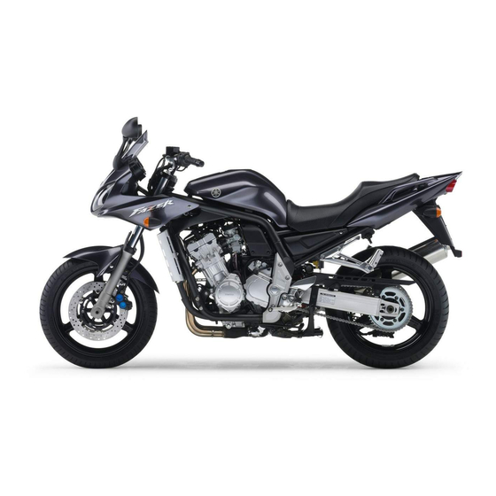
As the owner of an FZS1000, you are benefiting from Yamaha’s vast experience and newest technology regarding the design and manufacture of high-quality products, which have earned Yamaha a reputation for dependability.
Please take the time to read this manual thoroughly, so as to enjoy all advantages of your FZS1000. The owner’s manual does not only instruct you in how to operate, inspect and maintain your motorcycle, but also in how to safeguard yourself and others from trouble and injury.
In addition, the many tips given in this manual will help keep your motorcycle in the best possible condition. If you have any further questions, do not hesitate to contact your Yamaha dealer.
The Yamaha team wishes you many safe and pleasant rides. So, remember to put safety first!

|
IMPORTANT MANUAL INFORMATION |
EAU00005 |
Particularly important information is distinguished in this manual by the following notations:
The Safety Alert Symbol means ATTENTION! BECOME ALERT! YOUR SAFETY IS
INVOLVED!
|
WARNING |
Failure to follow WARNING instructions could result in severe injury or death to the |
|
|
motorcycle operator, a bystander, or a person inspecting or repairing the |
||
|
motorcycle. |
||
|
CAUTION: |
A CAUTION indicates special precautions that must be taken to avoid damage to the |
|
|
motorcycle. |
||
NOTE: A NOTE provides key information to make procedures easier or clearer.
NOTE:
●This manual should be considered a permanent part of this motorcycle and should remain with it even if the motorcycle is subsequently sold.
●Yamaha continually seeks advancements in product design and quality. Therefore, while this manual contains the most current product information available at the time of printing, there may be minor discrepancies between your motorcycle and this manual. If you have any questions concerning this manual, please consult your Yamaha dealer.

IMPORTANT MANUAL INFORMATION
EW000002
 WARNING
PLEASE READ THIS MANUAL CAREFULLY AND COMPLETELY BEFORE OPERATING THIS MOTORCYCLE.

IMPORTANT MANUAL INFORMATION
EAU04229
FZS1000
OWNER’S MANUAL
© 2001 by Yamaha Motor Co., Ltd. 1st edition, June 2001
All rights reserved.
Any reprinting or unauthorized use without the written permission of Yamaha Motor Co., Ltd.
is expressly prohibited. Printed in Japan.

|
EAU00009 |
TABLE OF CONTENTS |
|
1 |
GIVE SAFETY THE RIGHT OF WAY |
1 |
|
|
2 |
DESCRIPTION |
2 |
|
|
3 |
INSTRUMENT AND CONTROL FUNCTIONS |
3 |
|
|
4 |
PRE-OPERATION CHECKS |
4 |
|
|
5 |
OPERATION AND IMPORTANT RIDING POINTS |
5 |
|
|
6 |
PERIODIC MAINTENANCE AND MINOR REPAIR |
6 |
|
|
7 |
MOTORCYCLE CARE AND STORAGE |
7 |
|
|
8 |
SPECIFICATIONS |
8 |
|
|
9 |
CONSUMER INFORMATION |
9 |
|
INDEX

 GIVE SAFETY THE RIGHT OF WAY

 GIVE SAFETY THE RIGHT OF WAY
|
GIVE SAFETY THE RIGHT OF WAY ………………………………………… |
1-1 |
1

|
GIVE SAFETY THE RIGHT OF WAY |
EAU00021 |
Motorcycles are fascinating vehicles, which can give you an unsurpassed feeling of power and freedom. However, they also impose certain limits, which you must accept; even the best motorcycle does not ignore the laws of physics.
1
Regular care and maintenance are essential for preserving value and operating condition of your motorcycle. Moreover, what is true for the motorcycle is also true for the rider: good performance depends on being in good shape. Riding under the influence of medication, drugs and alcohol is, of course, out of the question. Motorcycle riders—more than car drivers—must always be at their mental and physical best. Under the influence of even small amounts of alcohol, there is a tendency to take dangerous risks.
Protective clothing is as essential for the motorcycle rider as seat belts are for car drivers and passengers. Always wear a complete motorcycle suit (whether made of leather or tear-resistant synthetic materials with protectors), sturdy boots, motorcycle gloves and a properly fitting helmet. Optimum protective wear, however, should not encourage carelessness. Although full-coverage helmets and suits, in particular, create an illusion of total safety and protection, motorcyclists will always be vulnerable. Riders who lack critical self-control run the risk of going too fast and are apt to take chances. This is even more dangerous in wet weather. The good motorcyclist rides safely, predictably and defensively—avoiding all dangers, including those caused by others.
Enjoy your ride!
1-1
![]()
DESCRIPTION |
|
|
Left view ………………………………………………………………………………… |
2-1 |
|
Right view………………………………………………………………………………. |
2-2 |
|
Controls and instruments …………………………………………………………. |
2-3 |
2

Left view
2
|
1. Front fork compression |
8. Seat lock/helmet holder |
(page 3-11/page 3-12) |
|
|
damping force adjusting screw |
(page 3-14) |
9. Shock absorber assembly |
|
|
2. Front fork rebound damping |
compression damping force |
||
|
force adjusting screw |
(page 3-14) |
adjusting screw |
(page 3-16) |
|
3. Front fork spring preload |
10. Shock absorber assembly |
||
|
adjusting bolt |
(page 3-13) |
spring preload adjusting ring |
(page 3-15) |
|
4. Air filter element |
(page 6-15) |
11. Shock absorber assembly |
|
|
5. Fuses |
(page 6-36) |
rebound damping force |
|
|
6. Storage compartment |
(page 3-12) |
adjusting knob |
(page 3-16) |
|
7. Grab bar |
12. Shift pedal |
(page 3-8) |
2-1

DESCRIPTION
Right view
2
|
13. Owner’s tool kit |
(page 6-1) |
18. Engine oil filter cartridge |
(page 6-10) |
|
14. Rear brake fluid reservoir |
(page 6-27) |
19. Engine oil level check window |
(page 6-9) |
|
15. Battery |
(page 6-35) |
20. Brake pedal |
(page 3-8) |
|
16. Front brake fluid reservoir |
(page 6-27) |
21. Coolant reservoir |
(page 6-12) |
|
17. Radiator cap |
(page 6-14) |
2-2

DESCRIPTION
Controls and instruments
2
|
1. Clutch lever |
(page 3-7) |
6. Tachometer unit |
(page 3-4) |
|
2. Left handlebar switches |
(page 3-6) |
7. Fuel gauge |
(page 3-5) |
|
3. Starter (choke) lever |
(page 3-11) |
8. Right handlebar switches |
(page 3-7) |
|
4. Speedometer unit |
(page 3-3) |
9. Brake lever |
(page 3-8) |
|
5. Main switch/steering lock |
(page 3-1) |
10. Throttle grip |
(page 6-19) |
2-3

INSTRUMENT AND CONTROL FUNCTIONS
|
Main switch/steering lock ………………………………. |
3-1 |
|
Indicator and warning lights ………………………….. |
3-2 |
|
Speedometer unit ………………………………………… |
3-3 |
|
Tachometer unit …………………………………………… |
3-4 |
|
Self-diagnosis devices ………………………………….. |
3-5 |
|
Fuel gauge ………………………………………………….. |
3-5 |
|
Anti-theft alarm (optional) ……………………………… |
3-6 |
|
Handlebar switches ……………………………………… |
3-6 |
|
Clutch lever …………………………………………………. |
3-7 |
|
Shift pedal …………………………………………………… |
3-8 |
|
Brake lever ………………………………………………….. |
3-8 |
|
Brake pedal …………………………………………………. |
3-8 |
|
Fuel tank cap ………………………………………………. |
3-9 |
|
Fuel …………………………………………………………… |
3-9 |
||
|
Fuel tank breather hose ……………………………… |
3-10 |
||
|
Starter (choke) lever……………………………………. |
3-11 |
||
|
Seat …………………………………………………………. |
3-11 |
||
|
Helmet holder ……………………………………………. |
3-12 |
||
|
Storage compartment |
3-12 |
||
|
3 |
|||
|
Adjusting the front fork |
3-13 |
||
|
…………Adjusting the shock absorber assembly |
3-15 |
||
|
EXUP system ……………………………………………. |
3-17 |
||
|
Sidestand …………………………………………………. |
3-17 |
||
|
Ignition circuit cut-off system ……………………….. |
3-18 |

|
INSTRUMENT AND CONTROL FUNCTIONS |
EAU00027 |
3
1. Push.
2. Turn.
Main switch/steering lock
The main switch/steering lock controls the ignition and lighting systems, and is used to lock the steering. The various positions are described below.
EAU00036
ON
All electrical systems are supplied with power, and the engine can be started. The key cannot be removed.
EAU00038
LOCK
The steering is locked, and all electrical systems are off. The key can be removed.
To lock the steering
1.Turn the handlebars all the way to the left.
2.Push the key in from the “OFF” position, and then turn it to “LOCK” while still pushing it.
3.Remove the key.
EW000016
 WARNING
_
Never turn the key to “OFF” or “LOCK” while the motorcycle is moving, otherwise the electrical systems will be switched off, which may result in loss of control or an accident. Make sure that the motorcycle is stopped before turning the key to “OFF” or “LOCK”.
_
OFF
All electrical systems are off. The key can be removed.
To unlock the steering
Push the key in, and then turn it to “OFF” while still pushing it.
3-1

INSTRUMENT AND CONTROL FUNCTIONS
EAU04300
(Parking)
The steering is locked, the taillights and auxiliary lights are on, and the hazard light can be turned on, but all other electrical systems are off. The key can be removed.
The steering must be locked before the key can be turned to “  ”.
”.
ECA00043
CAUTION:
Do not use the parking position for an extended length of time, otherwise the battery may discharge.
1.Left turn signal indicator light “  ”
”
2.Neutral indicator light “  ”
”
3.High beam indicator light “ ”
”
4.Oil level warning light “ 

 ”
”
5.Right turn signal indicator light “  ”
”
6.Coolant temperature warning light “  ”
”
7.Fuel level warning light “  ”
”
EAU03034
Indicator and warning lights
EAU04121
EAU00063
High beam indicator light “ ”
”
This indicator light comes on when the high beam of the headlight is switched on.
|
EAU04301 |
|
|
Oil level warning light “ |
” |
This warning light comes on when the 3 engine oil level is low.
The electrical circuit of the warning light can be checked according to the following procedure.
1.Turn the key to “ON”.
2.If the warning light does not come on for a few seconds, then go off, have a Yamaha dealer check the electrical circuit.
Turn signal indicator lights “  ” NOTE:
_
and “  ”
”
The corresponding indicator light flashes when the turn signal switch is pushed to the left or right.
Even if the oil level is sufficient, the warning light may flicker when riding on a slope or during sudden acceleration or deceleration, but this is not a malfunction.
EAU00061 _
Neutral indicator light “  ”
”
This indicator light comes on when the transmission is in the neutral position.
3-2

INSTRUMENT AND CONTROL FUNCTIONS
3
1.Left turn signal indicator light “  ”
”
2.Neutral indicator light “  ”
”
3.High beam indicator light “ ”
”
4.Oil level warning light “ 

 ”
”
5.Right turn signal indicator light “  ”
”
6.Coolant temperature warning light “  ”
”
7.Fuel level warning light “  ”
”
EAU04302
Coolant temperature warning light
“  ”
”
This warning light comes on when the engine overheats. When this occurs, stop the engine immediately and allow the engine to cool.
The electrical circuit of the warning light can be checked according to the following procedure.
1. Turn the key to “ON”.
2.If the warning light does not come on for a few seconds, then go off, have a Yamaha dealer check the electrical circuit.
EC000002
CAUTION:
Do not operate the engine if it is overheated.
EAU04303
Fuel level warning light “  ”
”
This warning light comes on when the fuel level drops below approximately 4 L. When this occurs, refuel as soon as possible.
The electrical circuit of the warning light can be checked according to the following procedure.
1.Turn the key to “ON”.
2.If the warning light does not come on for a few seconds, then go off, have a Yamaha dealer check the electrical circuit.
1.Speedometer
2.Odometer/tripmeter
3.“SELECT” button
4.“RESET” button
EAU04289
Speedometer unit
The speedometer unit is equipped with the following:
●an odometer
●two tripmeters
When set to “ODO”, the motorcycle’s total mileage is indicated.
When set to “TRIP 1” or “TRIP 2”, the motorcycle’s mileage since the tripmeter was last reset is indicated. The tripmeters can be used together with the fuel gauge to estimate the distance that can be traveled on a full tank of fuel.
3-3

INSTRUMENT AND CONTROL FUNCTIONS
This information will enable you to plan future fuel stops.
To set a mode
Push the “SELECT” button to change between the odometer mode “ODO”, and the tripmeter modes “TRIP 1” and “TRIP 2” in the following order:
ODO → TRIP 1 → TRIP 2 → ODO
To reset a meter
To reset either tripmeter 1 or 2 to 0.0, select either by pushing the “SELECT” button, and then push the “RESET” button for at least one second.
1.Tachometer
2.Tachometer red zone
3.Clock
EAU03954
Tachometer unit
The electric tachometer allows the rider to monitor the engine speed and keep it within the ideal power range.
EC000003
CAUTION:
Do not operate the engine in the tachometer red zone.
Red zone: 11,500 r/min and above
This tachometer unit is equipped with a clock.
To set the clock:
1.Push both the “SELECT” and “RESET” buttons for at least two seconds.
2.When the hour digits start flashing,
push the “RESET” button to set the hours.
3. Push the “SELECT” button to 3 change the minutes.
4.When the minute digits start flashing, push the “RESET” button to set the minutes.
5.Push the “SELECT” button to start the clock.
NOTE:
_
After setting the clock, be sure to push the “SELECT” button before turning the key to “OFF”, otherwise the clock will not be set.
_
3-4

INSTRUMENT AND CONTROL FUNCTIONS
EAU04290
Self-diagnosis devices
This model is equipped with a self-di- agnosis device for the following electrical circuits:
● throttle position sensor ● speed sensor
3
● EXUP system ● overturn switch
If any of those circuits are defective, the tachometer will repeatedly display the following error code:
|
0 r/min for |
Circuit-specific |
Current |
|
|
number of r/min |
engine |
||
|
3 seconds |
|||
|
for 2.5 seconds |
speed for |
||
|
(See the table |
3 seconds |
||
|
below.) |
Use the chart below to identify the faulty electrical circuit.
|
Specific r/min |
Faulty electrical circuit |
|
3,000 r/min |
Throttle position sensor |
|
4,000 r/min |
Speed sensor |
|
7,000 r/min |
EXUP system |
|
9,000 r/min |
Overturn switch |
If the tachometer displays such an error code, note the circuit-specific number of r/min, and then have a Yamaha dealer check the motorcycle.
EC000004
CAUTION:
When the tachometer displays an error code, the motorcycle should be checked as soon as possible in order to avoid engine damage.
1. Fuel gauge
EAU00110
Fuel gauge
The fuel gauge indicates the amount of fuel in the fuel tank. The needle moves towards “E” (Empty) as the fuel level decreases. When the needle reaches “E”, approximately 4 L of fuel remain in the fuel tank. If this occurs, refuel as soon as possible.
NOTE:
_
Do not allow the fuel tank to empty itself completely.
_
3-5
![]()
INSTRUMENT AND CONTROL FUNCTIONS
EAU00109
Anti-theft alarm (optional)
This motorcycle can be equipped with an optional anti-theft alarm by a Yamaha dealer. Contact a Yamaha dealer for more information.
1. Pass switch “PASS”
2. Dimmer switch “ /
/  ”
”
3. Turn signal switch “  /
/  ”
”
4. Horn switch “  ”
”
5. Hazard switch “  ”
”
EAU03889
Turn signal switch “  /
/  ”
”
To signal a right-hand turn, push this switch to “ ”. To signal a left-hand turn, push this switch to “
  ”. When released, the switch returns to the center position. To cancel the turn signal lights, push the switch in after it has re-
|
turned to the center position. |
3 |
|
|
EAU00129 |
||
|
Horn switch “ |
” |
|
|
Press this switch to sound the horn. |
||
|
EAU03826 |
||
|
EAU00118 Hazard switch “ |
” |
Handlebar switches
EAU00120
Pass switch “PASS”
Press this switch to flash the headlight.
EAU03888
Dimmer switch “ /
/  ”
”
Set this switch to “ ” for the high beam and to “
 ” for the low beam.
With the key in the “ON” or “  ” position, use this switch to turn on the hazard light (simultaneous flashing of all turn signal lights).
The hazard light is used in case of an emergency or to warn other drivers when your motorcycle is stopped where it might be a traffic hazard.
EC000006
CAUTION:
_
Do not use the hazard light for an extended length of time, otherwise the battery may discharge.
_
3-6

INSTRUMENT AND CONTROL FUNCTIONS
EAU00143
Start switch “  ”
”
Push this switch to crank the engine with the starter.
EC000005
CAUTION:
See page 5-1 for starting instruc-
tions prior to starting the engine.
3
1.Engine stop switch “  /
/  ”
”
2.Light switch “  /
/  /
/  ”
”
3.Start switch “  ”
”
EAU03890
Engine stop switch “  /
/  ”
”
Set this switch to “  ” before starting the engine. Set this switch to “
  ” to stop the engine in case of an emergency, such as when the motorcycle overturns or when the throttle cable is stuck.
EAU03955
Light switch “  /
/  /
/  ”
”
Set this switch to “  ” to turn on the auxiliary lights, meter lighting and taillights. Set the switch to “
  ” to turn on the headlight also. Set this switch to “
  ” to turn off all the lights.
1. Clutch lever
EAU00152
Clutch lever
The clutch lever is located at the left handlebar grip. To disengage the clutch, pull the lever toward the handlebar grip. To engage the clutch, release the lever. The lever should be pulled rapidly and released slowly for smooth clutch operation.
The clutch lever is equipped with a clutch switch, which is part of the ignition circuit cut-off system. (See page 3-18 for an explanation of the ignition circuit cut-off system.)
3-7

INSTRUMENT AND CONTROL FUNCTIONS
1. Shift pedal
EAU00157
Shift pedal
The shift pedal is located on the left side of the engine and is used in combination with the clutch lever when shifting the gears of the 6-speed con- stant-mesh transmission equipped on this motorcycle.
1.Brake lever
2.Brake lever position adjusting dial
3.Arrow mark
a.Distance between brake lever and handlebar grip
EAU00161
Brake lever
The brake lever is located at the right handlebar grip. To apply the front brake, pull the lever toward the handlebar grip. The brake lever is equipped with a position adjusting dial. To adjust the distance between the brake lever and the handlebar grip, turn the adjusting dial while holding the lever pushed away from the handlebar grip. Make sure that the appropriate setting on the adjusting dial is aligned with the arrow mark on the brake lever.
3
1. Brake pedal
EAU00162
Brake pedal
The brake pedal is on the right side of the motorcycle. To apply the rear brake, press down on the brake pedal.
3-8

INSTRUMENT AND CONTROL FUNCTIONS
3
1.Fuel tank cap lock cover
2.Unlock.
EAU02935
Fuel tank cap
To open the fuel tank cap
Open the fuel tank cap lock cover, insert the key into the lock, and then turn it 1/4 turn clockwise. The lock will be released and the fuel tank cap can be opened.
To close the fuel tank cap
1.Push the fuel tank cap into position with the key inserted in the lock.
2.Turn the key counterclockwise to the original position, remove it, and then close the lock cover.
NOTE:
The fuel tank cap cannot be closed unless the key is in the lock. In addition, the key cannot be removed if the cap is not properly closed and locked.
EWA00025
 WARNING
Make sure that the fuel tank cap is properly closed before riding.
1.Fuel tank filler tube
2.Fuel level
EAU03753
Fuel
Make sure that there is sufficient fuel in the tank. Fill the fuel tank to the bottom of the filler tube as shown.
EW000130
WARNING
_
●Do not overfill the fuel tank, otherwise it may overflow when the fuel warms up and expands.
●Avoid spilling fuel on the hot engine.
_
3-9

INSTRUMENT AND CONTROL FUNCTIONS
EAU00185
CAUTION:
Immediately wipe off spilled fuel with a clean, dry, soft cloth, since fuel may deteriorate painted surfaces or plastic parts.
EAU04255
Recommended fuel: REGULAR UNLEADED GASOLINE ONLY
Fuel tank capacity: Total amount:
21 L
Reserve amount: 4 L
ECA00104
CAUTION:
Use only unleaded gasoline. The use of leaded gasoline will cause severe damage to internal engine parts, such as the valves and piston rings, as well as to the exhaust system.
Your Yamaha engine has been designed to use regular unleaded gasoline with a research octane number of 91 or higher. If knocking (or pinging) occurs, use a gasoline of a different brand or premium unleaded fuel. Use of unleaded fuel will extend spark plug life and reduce maintenance costs.
3
1.Fuel tank breather hose
2.Original position (white mark)
EAU02955
Fuel tank breather hose
Before operating the motorcycle:
●Check the fuel tank breather hose connection.
●Check the fuel tank breather hose for cracks or damage, and replace it if damaged.
●Make sure that the end of the fuel tank breather hose is not blocked, and clean it if necessary.
3-10

INSTRUMENT AND CONTROL FUNCTIONS
3
1. Starter (choke) lever “ 

 ”
”
EAU03839
Starter (choke) lever “ 

 ”
”
Starting a cold engine requires a richer air-fuel mixture, which is supplied by the starter (choke).
Move the lever in direction a to turn on the starter (choke).
Move the lever in direction b to turn off the starter (choke).
1.Seat lock
2.Unlock.
EAU03956
Seat
To remove the seat
1.Insert the key into the seat lock, and then turn it clockwise.
2.While holding the key in that position, lift the rear of the seat, and then pull the seat off.
1.Projection
2.Seat holder
To install the seat
1.Insert the projection on the front of the seat into the seat holder as shown.
2.Push the rear of the seat down to lock it in place.
3.Remove the key.
NOTE:
_
Make sure that the seat is properly secured before riding.
_
3-11

INSTRUMENT AND CONTROL FUNCTIONS
1.Helmet holder
2.Unlock.
EAU04291
Helmet holder
To open the helmet holder, insert the key into the seat lock, and then turn the key as shown.
To lock the helmet holder, turn the key to the original position, and then remove it.
EW000030
 WARNING
Never ride with a helmet attached to the helmet holder, since the helmet may hit objects, causing loss of control and possibly an accident.
1. Storage compartment
EAU04292
Storage compartment
This storage compartment is designed to hold an optional genuine Yamaha U-LOCK. (Other locks may not fit.) When placing a U-LOCK in the storage compartment, securely fasten it with the straps. When the U-LOCK is not in the storage compartment, be sure to secure the straps to prevent losing them.
3
1.U-LOCK bar
2.Strap (× 2)
3.Lock of the U-LOCK
When storing the owner’s manual or other documents in the storage compartment, be sure to wrap them in a plastic bag so that they will not get wet. When washing the motorcycle, be careful not to let any water enter the storage compartment.
3-12

INSTRUMENT AND CONTROL FUNCTIONS
EAU04293
Adjusting the front fork
This front fork is equipped with spring preload adjusting bolts, rebound damping force adjusting screws and compression damping force adjusting screws.
EW000035
3  WARNING
Always adjust both fork legs equally, otherwise poor handling and loss of stability may result.
1. Spring preload adjusting bolt
Spring preload
To increase the spring preload and thereby harden the suspension, turn the adjusting bolt on each fork leg in direction a. To decrease the spring preload and thereby soften the suspension, turn the adjusting bolt on each fork leg in direction b.
1.Current setting
2.Front fork cap bolt
NOTE:
_
Align the appropriate groove on the adjusting mechanism with the top of the front fork cap bolt.
_
CI-15E
|
Setting |
|
|
Minimum (soft) |
5* |
|
Standard |
2 |
|
Maximum (hard) |
1 |
* Adjusting bolt fully turned in direction b
3-13

INSTRUMENT AND CONTROL FUNCTIONS
1. Rebound damping force adjusting screw
Rebound damping force
To increase the rebound damping force and thereby harden the rebound damping, turn the adjusting screw on each fork leg in direction a. To decrease the rebound damping force and thereby soften the rebound damping, turn the adjusting screw on each fork leg in direction b.
|
Minimum (soft) |
17 clicks in direction b* |
|
Standard |
7 clicks in direction b* |
|
Maximum (hard) |
1 click in direction b* |
* With the adjusting screw fully turned in direction a
1. Compression damping force adjusting screw
Compression damping force
To increase the compression damping force and thereby harden the compression damping, turn the adjusting screw on each fork leg in direction a. To decrease the compression damping force and thereby soften the compression damping, turn the adjusting screw on each fork leg in direction b.
|
Minimum (soft) |
21 clicks in direction b* |
|
Standard |
6 clicks in direction b* |
|
Maximum (hard) |
1 click in direction b* |
* With the adjusting screw fully turned in direction a
EC000015
CAUTION:
|
_ |
|||||
|
Never attempt to turn an adjusting |
|||||
|
mechanism beyond the maximum |
|||||
|
or minimum settings. |
|||||
|
_ |
|||||
|
_NOTE: |
|||||
|
Although the total number of clicks of a |
3 |
||||
|
damping force adjusting mechanism |
|||||
|
may not exactly match the above spec- |
|||||
|
ifications due to small differences in |
|||||
|
production, the actual number of clicks |
|||||
|
always represents the entire adjusting |
|||||
|
range. To obtain a precise adjustment, |
|||||
|
it would be advisable to check the num- |
|||||
|
ber of clicks of each damping force ad- |
|||||
|
justing mechanism and to modify the |
|||||
|
specifications as necessary. |
|||||
|
_ |
3-14

INSTRUMENT AND CONTROL FUNCTIONS
EAU04295
|
Adjusting the shock absorber |
||||
|
assembly |
||||
|
This shock absorber assembly is |
||||
|
equipped with a spring preload adjust- |
||||
|
ing ring, a rebound damping force ad- |
||||
|
justing knob and a compression |
||||
|
3 |
damping force adjusting screw. |
|||
|
EC000015 |
||||
|
CAUTION: |
||||
|
Never attempt to turn an adjusting |
||||
|
mechanism beyond the maximum |
||||
|
or minimum settings. |
||||
1.Spring preload adjusting ring
2.Special wrench
3.Position indicator
Spring preload
To increase the spring preload and thereby harden the suspension, turn the adjusting ring in direction a. To decrease the spring preload and thereby soften the suspension, turn the adjusting ring in direction b.
NOTE:
_
●Align the appropriate notch in the adjusting ring with the position indicator on the shock absorber.
●Use the special wrench included in the owner’s tool kit to make the adjustment.
_
CI-10E
|
Setting |
|
|
Minimum (soft) |
1 |
|
Standard |
6 |
|
Maximum (hard) |
11 |
3-15
![]()
INSTRUMENT AND CONTROL FUNCTIONS
1. Rebound damping force adjusting knob
Rebound damping force
To increase the rebound damping force and thereby harden the rebound damping, turn the adjusting knob in direction a. To decrease the rebound damping force and thereby soften the rebound damping, turn the adjusting knob in direction b.
|
Minimum (soft) |
20 clicks in direction b* |
|
Standard |
10 clicks in direction b* |
|
Maximum (hard) |
3 clicks in direction b* |
* With the adjusting knob fully turned in direction a
1. Compression damping force adjusting screw
Compression damping force
To increase the compression damping force and thereby harden the compression damping, turn the adjusting screw in direction a. To decrease the compression damping force and thereby soften the compression damping, turn the adjusting screw in direction b.
|
Minimum (soft) |
1 click in direction a* |
|
Standard |
7 clicks in direction a* |
|
Maximum (hard) |
12 clicks in direction a* |
* With the adjusting screw fully turned in direction b
NOTE:
_
Although the total number of clicks of a damping force adjusting mechanism may not exactly match the above specifications due to small differences in production, the actual number of clicks always represents the entire adjusting range. To obtain a precise adjustment, 3 it would be advisable to check the num-
ber of clicks of each damping force adjusting mechanism and to modify the specifications as necessary.
_
3-16

INSTRUMENT AND CONTROL FUNCTIONS
EAU00315
 WARNING
This shock absorber contains highly pressurized nitrogen gas. For proper handling, read and understand the following information before handling the shock absorber.
3The manufacturer cannot be held responsible for property damage or
personal injury that may result from improper handling.
●Do not tamper with or attempt to open the gas cylinder.
●Do not subject the shock absorber to an open flame or other high heat sources, otherwise it may explode due to excessive gas pressure.
●Do not deform or damage the gas cylinder in any way, as this will result in poor damping performance.
●Always have a Yamaha dealer service the shock absorber.
EAU01571
EXUP system
This motorcycle is equipped with Yamaha’s EXUP (EXhaust Ultimate Power valve) system. This system boosts engine power by means of a valve that regulates the diameter of the exhaust pipe. The EXUP system valve is constantly adjusted in accordance with the engine speed by a computercontrolled servomotor.
EC000027
CAUTION:
●The EXUP system has been set and extensively tested at the Yamaha factory. Changing these settings without sufficient technical knowledge may result in poor performance of or damage to the engine.
●If the EXUP system does not operate, have a Yamaha dealer check it.
EAU00330
Sidestand
The sidestand is located on the left side of the frame. Raise the sidestand or lower it with your foot while holding the motorcycle upright.
NOTE:
_
The built-in sidestand switch is part of the ignition circuit cut-off system, which cuts the ignition in certain situations. (See further down for an explanation of the ignition circuit cut-off system.)
_
3-17

INSTRUMENT AND CONTROL FUNCTIONS
EW000044
 WARNING
The motorcycle must not be ridden with the sidestand down, or if the sidestand cannot be properly moved up (or does not stay up), otherwise the sidestand could contact the ground and distract the operator, resulting in a possible loss of control. Yamaha’s ignition circuit cut-off system has been designed to assist the operator in fulfilling the responsibility of raising the sidestand before starting off. Therefore, check this system regularly as described below and have a Yamaha dealer repair it if it does not function properly.
EAU03741
Ignition circuit cut-off system
The ignition circuit cut-off system (comprising the sidestand switch, clutch switch and neutral switch) has the following functions.
●It prevents starting when the transmission is in gear and the sidestand is up, but the clutch lever is not pulled.
●It prevents starting when the transmission is in gear and the clutch lever is pulled, but the sidestand is still down.
●It cuts the running engine when
the transmission is in gear and the sidestand is moved down.
Periodically check the operation of the ignition circuit cut-off system according to the following procedure.
EW000046
WARNING
_
●The vehicle must be placed on the centerstand during this inspection.
●If a malfunction is noted, have a
|
Yamaha dealer check the sys- |
|
|
tem before riding. |
3 |
_
3-18