Материал из BikesWiki — энциклопедия японских мотоциклов
Перейти к: навигация, поиск

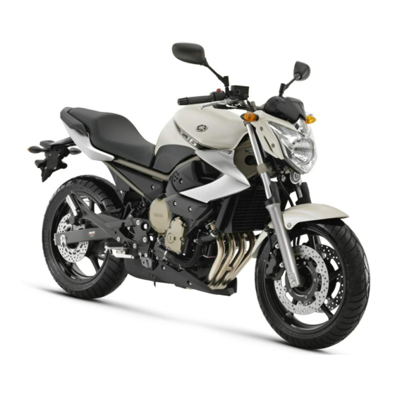
Yamaha XJ6 Diversion
Ниже представлены прямые ссылки на скачку сервисной документации.
Для Yamaha XJ6 Diversion
- Руководство пользователя (Owners Manual) для Yamaha XJ6 Diversion (на русском)
- Сервисный мануал (Service Manual) для Yamaha XJ6S(A) (Европа, 2009)
- Сервисный мануал (Service Manual) для Yamaha FZ6R (США, 2009)
- Каталог запчастей (микрофиши) для Yamaha XJ6N (A) (2010)
- Каталог запчастей (микрофиши) для Yamaha XJ6S (2010)
- Каталог запчастей (микрофиши) для Yamaha XJ6SA (2010)
Обзор модели
- Yamaha XJ6 Diversion
Источник — «https://bikeswiki.ru/index.php?title=Yamaha_XJ6_Diversion:_мануалы&oldid=10057»
Категория:
- Сервисная документация
- Manuals
- Brands
- Yamaha Manuals
- Motorcycle
- XJ6
- Owner’s manual
-
Contents
-
Table of Contents
-
Troubleshooting
-
Bookmarks
Quick Links
OWNER’S MANUAL
XJ6
XJ6 ABS
MOTORCYCLE
Read this manual carefully before oper-
ating this vehicle.
XJ6N
XJ6NA
B61-28199-E1
Related Manuals for Yamaha XJ6
Summary of Contents for Yamaha XJ6
-
Page 1
OWNER’S MANUAL XJ6 ABS MOTORCYCLE Read this manual carefully before oper- ating this vehicle. XJ6N XJ6NA B61-28199-E1… -
Page 2
EAU69471 Read this manual carefully before operating this vehicle. This manual should stay with this vehicle if it is sold. YAMAHA MOTOR ELECTRONICS CO., LTD. 1450-6, Mori, Mori-machi, Shuchi-gun, Shizuoka-ken, 437-0292 Japan DECLARATION of CONFORMITY Product: IMMOBILIZER Model: 5VS-00 Supplied by… -
Page 3
EAU10103 Welcome to the Yamaha world of motorcycling! As the owner of the XJ6N / XJ6NA, you are benefiting from Yamaha’s vast expe- rience and newest technology regarding the design and manufacture of high- quality products, which have earned Yamaha a reputation for dependability. -
Page 4: Important Manual Information
*Product and specifications are subject to change without notice. EAU10201 XJ6N / XJ6NA OWNER’S MANUAL ©2015 by Yamaha Motor Co., Ltd. 1st edition, August 2015 All rights reserved. Any reprinting or unauthorized use without the written permission of Yamaha Motor Co., Ltd.
-
Page 5: Table Of Contents
Table of contents Safety information ……1-1 Periodic maintenance and adjustment ……..6-1 Description ……..2-1 Owner’s tool kit……. 6-2 Left view ……….2-1 Periodic maintenance chart for the Right view……..2-2 emission control system….6-3 Controls and instruments….2-3 General maintenance and lubrication chart……6-4 Instrument and control functions..3-1 Removing and installing the Immobilizer system ……3-1…
-
Page 6
Table of contents Battery ………. 6-33 Replacing the fuses…… 6-34 Replacing the headlight bulb..6-36 Replacing the auxiliary light bulb ……….. 6-38 Replacing the brake/tail light bulb ……….. 6-39 Replacing a turn signal light bulb ……….. 6-39 Replacing the license plate light bulb ……….. -
Page 7: Safety Information
Safety information EAU1028B an accident or equipment damage. See page 4-1 for a list of pre-operation checks. Be a Responsible Owner This motorcycle is designed to As the vehicle’s owner, you are re- carry the operator and a passen- sponsible for the safe and proper oper- ger.
-
Page 8
Safety information Many accidents involve inexperi- • The passenger should always enced operators. In fact, many op- hold onto the operator, the seat erators who have been involved in strap or grab bar, if equipped, accidents do not even have a cur- with both hands and keep both rent motorcycle license. -
Page 9
Safety information Avoid Carbon Monoxide Poisoning extra care when riding a motorcycle All engine exhaust contains carbon that has added cargo or accessories. monoxide, a deadly gas. Breathing Here, along with the information about carbon monoxide can cause head- accessories below, are some general aches, dizziness, drowsiness, nausea, guidelines to follow if loading cargo to confusion, and eventually death. -
Page 10
Genuine does not in any way reduce Yamaha accessories, which are avail- ground clearance or cornering able only from a Yamaha dealer, have clearance, limit suspension travel, been designed, tested, and approved steering travel or control opera- by Yamaha for use on your vehicle. -
Page 11: Specifications
Safety information operator and may limit control torcycle, such as the frame or up- ability, therefore, such accesso- per front fork triple clamp (and not, ries are not recommended. for example, to rubber-mounted Use caution when adding electri- handlebars or turn signals, or cal accessories.
-
Page 12: Description
Description EAU63371 Left view 1. Air filter element (page 6-16) 2. Idle adjusting screw (page 6-17) 3. Seat lock (page 3-18) 4. Fuses (page 6-34) 5. Owner’s tool kit (page 6-2) 6. Storage compartment (page 3-20) 7. Shift pedal (page 3-12) 8.
-
Page 13: Right View
Description EAU63391 Right view 1. Helmet holder (page 3-19) 2. Battery (page 6-33) 3. Rear brake fluid reservoir (page 6-25) 4. Engine oil filler cap (page 6-9) 5. Fuel tank cap (page 3-15) 6. Radiator cap (page 6-12) 7. Coolant reservoir (page 6-12) 8.
-
Page 14: Controls And Instruments
Description EAU63401 Controls and instruments 1. Clutch lever (page 3-12) 2. Left handlebar switches (page 3-10) 3. Main switch/steering lock (page 3-2) 4. Multi-function meter unit (page 3-6) 5. Front brake fluid reservoir (page 6-25) 6. Right handlebar switches (page 3-10) 7.
-
Page 15: Instrument And Control Functions
Do not grind any key or alter its cess, take the vehicle along with all shape. three keys to a Yamaha dealer to have Do not disassemble the plastic them re-registered. Do not use the key part of any key.
-
Page 16: Main Switch/Steering Lock
Instrument and control functions Keep the standard keys as well EAU10474 Main switch/steering lock as keys of other immobilizer systems away from this vehi- cle’s code re-registering key. Keep other immobilizer system keys away from the main switch as they may cause signal inter- ference.
-
Page 17
Instrument and control functions To unlock the steering EWA10062 WARNING Never turn the key to “OFF” or “LOCK” while the vehicle is moving. Otherwise the electrical systems will be switched off, which may result in loss of control or an accident. EAU10687 LOCK The steering is locked and all electrical… -
Page 18: Indicator Lights And Warning Lights
“ON”, or if the warning light remains on after confirming that the oil level is correct (see page 6-9), have a Yamaha dealer check the vehicle. 1. Turn signal indicator light “ ”…
-
Page 19
” The ABS may not work correctly. If any This warning light comes on or flashes of the above occurs, have a Yamaha if a problem is detected in the electrical dealer check the system as soon as circuit monitoring the engine. If this oc- possible. -
Page 20: Multi-Function Meter Unit
“ON”, making any setting changes to the or if the indicator light remains on, have multi-function meter unit. Changing a Yamaha dealer check the electrical settings while riding can distract the circuit. operator and increase the risk of an The self-diagnosis device also detects accident.
-
Page 21
Instrument and control functions Clock The key must be turned to “ON” before you can use the “SELECT” and “RESET” buttons. For the UK: To switch the speed- ometer and odometer/tripmeter displays between kilometers and miles, press the “SELECT” button for one second. -
Page 22
“ ” 0.70 Imp.gal), the left segment of the will flash repeatedly. If this occurs, fuel meter will start flashing, and the have a Yamaha dealer check the elec- odometer display will automatically trical circuit. change to the fuel reserve tripmeter mode “F-TRIP”… -
Page 23
Yamaha dealer check the vehicle. goes down. If the temperature does The self-diagnosis device also detects not go down, stop the engine. (See problems in the immobilizer system page 6-46.) -
Page 24: Handlebar Switches
” key and both standard keys to a 4. Horn switch “ ” 5. Hazard switch “ ” Yamaha dealer and have the stan- dard keys re-registered. Right ECA11591 NOTICE If the display indicates an error co- de, the vehicle should be checked as soon as possible in order to avoid engine damage.
-
Page 25
Instrument and control functions The hazard lights are used in case of an EAU12461 Turn signal switch “ ” emergency or to warn other drivers To signal a right-hand turn, push this when your vehicle is stopped where it switch to “ ”. -
Page 26: Clutch Lever
Instrument and control functions EAU12822 EAU12872 Clutch lever Shift pedal 1. Clutch lever 1. Shift pedal The clutch lever is located on the left The shift pedal is located on the left side of the handlebar. To disengage side of the motorcycle and is used in the clutch, pull the lever toward the combination with the clutch lever when handlebar grip.
-
Page 27: Brake Lever
Instrument and control functions EAU26825 EAU12944 Brake lever Brake pedal The brake lever is located on the right side of the handlebar. To apply the front brake, pull the lever toward the throttle grip. 1. Brake pedal The brake pedal is located on the right side of the motorcycle.
-
Page 28: Abs (For Abs Models)
This ABS has a test mode which EAU51802 ABS (for ABS models) allows the owner to experience The Yamaha ABS (Anti-lock Brake the pulsation at the brake lever or System) features a dual electronic con- brake pedal when the ABS is op- trol system, which acts on the front and erating.
-
Page 29: Fuel Tank Cap
Instrument and control functions EAU13075 EAU13222 Fuel tank cap Fuel Make sure there is sufficient gasoline in the tank. EWA10882 WARNING Gasoline and gasoline vapors are extremely flammable. To avoid fires and explosions and to reduce the risk of injury when refueling, follow these instructions.
-
Page 30
Your Yamaha engine has been de- signed to use regular unleaded gaso- line with a research octane number of 3-16… -
Page 31: Fuel Tank Breather Hose And Overflow Hose
Instrument and control functions EAU55512 EAU13434 Fuel tank breather hose and Catalytic converter overflow hose This model is equipped with a catalytic converter in the exhaust system. EWA10863 WARNING The exhaust system is hot after op- eration. To prevent a fire hazard or burns: …
-
Page 32: Seat
Instrument and control functions EAU32981 Seat Make sure that the seat is properly se- cured before riding. To remove the seat 1. Insert the key into the seat lock, and then turn it counterclockwise. 1. Seat lock 2. Unlock. 2. While holding the key in that posi- tion, lift the rear of the seat up, and then pull the seat off.
-
Page 33: Helmet Holder
Instrument and control functions 3. Place the helmet on the right side EAU46752 Helmet holder of the vehicle, and then install the seat. WARNING! Never ride with a helmet attached to the helmet holder, since the helmet may hit objects, causing loss of control and possibly an accident.
-
Page 34: Storage Compartment
Storage compartment Handlebar position The handlebar can be adjusted to one of two positions to suit the rider’s pref- erence. Have a Yamaha dealer adjust the position of the handlebar. 1. Storage compartment The storage compartment is located under the seat. (See page 3-18.) When storing the Owner’s Manual or…
-
Page 35: Adjusting The Shock Absorber Assembly
Do not dispose of a damaged or worn-out shock absorber as- sembly yourself. Take the shock absorber assembly to a Yamaha dealer for any service. 1. Extension bar 2. Special wrench 3. Spring preload adjusting ring 4.
-
Page 36: Sidestand
Therefore, check this system regularly and have a Yamaha dealer repair it if it does not function properly. 3-22…
-
Page 37
Does the engine start? The neutral switch may not be working correctly. The motorcycle should not be ridden until checked by a Yamaha dealer. With the engine still running: 6. Move the sidestand up. 7. Keep the clutch lever pulled. -
Page 38: For Your Safety — Pre-Operation Checks
Do not operate the vehicle if you find any problem. If a problem cannot be corrected by the procedures provided in this manual, have the vehicle inspected by a Yamaha dealer. Before using this vehicle, check the following points:…
-
Page 39
• Tighten if necessary. Instruments, lights, • Check operation. — signals and switches • Correct if necessary. • Check operation of ignition circuit cut-off system. Sidestand switch • If system is not working correctly, have Yamaha dealer 3-22 check vehicle. -
Page 40: Operation And Important Riding Points
This model is equipped with: there is a control or function you do not a lean angle sensor to stop the en- understand, ask your Yamaha dealer. gine in case of a turnover. In this EWA10272 case, the display will indicate error…
-
Page 41: Starting The Engine
The neutral indi- the clutch lever pulled and the cator light should come on. If not, sidestand up. ask a Yamaha dealer to check the See page 3-22 for more informa- electrical circuit. tion. 3. Start the engine by pushing the 1.
-
Page 42: Shifting
Operation and important riding points EAU16673 and drive train, which are not Shifting designed withstand shock of forced shifting. 1. Shift pedal 2. Neutral position Shifting gears lets you control the amount of engine power available for starting off, accelerating, climbing hills, etc.
-
Page 43: Tips For Reducing Fuel Consumption
The vehicle can now be operated nor- mally. ECA10311 NOTICE Keep the engine speed out of the tachometer red zone. If any engine trouble should oc- cur during the engine break-in period, immediately have a Yamaha dealer check the vehi- cle.
-
Page 44: Parking
Operation and important riding points EAU17214 Parking When parking, stop the engine, and then remove the key from the main switch. EWA10312 WARNING Since the engine and exhaust system can become very hot, park in a place where pedestri- ans or children are not likely to touch them and be burned.
-
Page 45: Periodic Maintenance And Adjustment
If you are not familiar with vehicle ser- vice, have a Yamaha dealer perform service. EWA15123 WARNING Turn off the engine when performing…
-
Page 46: Owner’s Tool Kit
If you do not have the tools or experi- ence required for a particular job, have a Yamaha dealer perform it for you.
-
Page 47: Periodic Maintenance Chart For The Emission Control System
From 50000 km (30000 mi), repeat the maintenance intervals starting from 10000 km (6000 mi). Items marked with an asterisk should be performed by a Yamaha dealer as they require special tools, data and technical skills. EAU63321…
-
Page 48: General Maintenance And Lubrication Chart
Periodic maintenance and adjustment EAU64031 General maintenance and lubrication chart ODOMETER CHECK OR READINGS MAINTENANCE JOB ITEM X 1000 km X 1000 mi √ Air filter element • Replace. • Check operation. √ √ √ √ √ Clutch • Adjust. •…
-
Page 49
Periodic maintenance and adjustment ODOMETER CHECK OR READINGS MAINTENANCE JOB ITEM X 1000 km X 1000 mi • Make sure that all nuts, bolts √ √ √ √ √ 13 * Chassis fasteners and screws are properly tight- ened. Brake lever pivot √… -
Page 50
Periodic maintenance and adjustment ODOMETER CHECK OR READINGS MAINTENANCE JOB ITEM X 1000 km X 1000 mi Lights, signals and • Check operation. √ √ √ √ √ √ 28 * • Adjust headlight beam. switches EAU18681 Air filter •… -
Page 51: Removing And Installing The Cowling And Panels
Periodic maintenance and adjustment To install the cowling EAU18724 Removing and installing the Place the cowling in the original posi- cowling and panels tion, and then install the bolts. The cowling and panels shown need to be removed to perform some of the EAU56070 maintenance jobs described in this chapter.
-
Page 52: Checking The Spark Plugs
The spark plugs are important engine components, which should checked periodically, preferably by a Yamaha dealer. Since heat and depos- its will cause any spark plug to slowly erode, they should be removed and checked in accordance with the peri- odic maintenance and lubrication 1.
-
Page 53: Engine Oil And Oil Filter Cartridge
Periodic maintenance and adjustment EAU46723 Engine oil and oil filter car- tridge The engine oil level should be checked before each ride. In addition, the oil must be changed and the oil filter car- tridge replaced at the intervals speci- fied in the periodic maintenance and lubrication chart.
-
Page 54
An oil filter wrench is available at a gasket to drain the oil from the Yamaha dealer. crankcase. 6. Apply a thin coat of clean engine oil to the O-ring of the new oil filter cartridge. -
Page 55
Periodic maintenance and adjustment 9. Refill with the specified amount of the recommended engine oil, and then install and tighten the oil filler cap. Recommended engine oil: See page 8-1. Oil quantity: Oil change: 2.50 L (2.64 US qt, 2.20 Imp.qt) With oil filter removal: 1. -
Page 56: Coolant
Yamaha dealer check and lubrication chart. the vehicle. 11. Turn the engine off, wait a few mi-…
-
Page 57
[EWA10382] be protected against frost and corrosion. If water has been added to the coolant, have a Yamaha dealer check the anti- freeze content of the coolant as soon as possible, otherwise the effectiveness of the coolant will be reduced. -
Page 58
Periodic maintenance and adjustment 1. Radiator cap 1. Bolt 2. Radiator cap retaining bolt 2. Coolant reservoir cover 3. Radiator cap retainer 3. Coolant reservoir 5. Remove the coolant reservoir 7. Drain the coolant from the coolant breather hose from the guide, and reservoir by turning it upside then remove the coolant reservoir down. -
Page 59
14. Install the coolant reservoir cap. the vehicle for coolant leakage. If 15. Start the engine, let it idle for sev- coolant is leaking, have a Yamaha eral minutes, and then turn it off. dealer check the cooling system. 16. Remove the radiator cap to check 20. -
Page 60: Replacing The Air Filter Element
If any hose is damaged, have a Yamaha dealer replace the hose before 1. Air filter case cover 2. Screw 4. Pull the air filter element out.
-
Page 61: Adjusting The Engine Idling Speed
1. Original position (paint mark) 8. Install the fuel tank bolts. 9. Install the seat. 1. Idle adjusting screw Engine idling speed: 1250–1350 r/min If the specified idling speed cannot be obtained as described above, have a Yamaha dealer make the adjustment. 6-17…
-
Page 62: Checking The Throttle Grip Free Play
Measure the throttle grip free play as and/or engine noise. To prevent this shown. from occurring, the valve clearance must be adjusted by a Yamaha dealer at the intervals specified in the periodic maintenance and lubrication chart. 1. Throttle grip free play Throttle grip free play: 3.0–5.0 mm (0.12–0.20 in)
-
Page 63: Tires
The tires must be checked before each ride. If the center tread depth reaches the specified limit, if the tire has a nail or glass fragments in it, or if the side- wall is cracked, have a Yamaha dealer replace the tire immediately. 6-19…
-
Page 64
EWA10472 their suitability for further use. WARNING EWA10902 Have a Yamaha dealer replace WARNING excessively worn tires. Besides The front and rear tires should being illegal, operating the vehi- be of the same make and de-… -
Page 65: Cast Wheels
160/60 ZR17M/C (69W) ride. If any damage is found, have Manufacturer/model: BRIDGESTONE/BT021R a Yamaha dealer replace the DUNLOP/SPORTMAX- wheel. Do not attempt even the ROADSMART smallest repair to the wheel. A de- FRONT and REAR:…
-
Page 66: Adjusting The Clutch Lever Free Play
Periodic maintenance and adjustment EAU46731 Adjusting the clutch lever free play 1. Locknut 2. Clutch lever free play adjusting nut 4. Tighten the locknut. 1. Clutch lever free play adjusting bolt 2. Clutch lever free play The clutch lever free play should mea- sure 10.0–15.0 mm (0.39–0.59 in) as shown.
-
Page 67: Checking The Brake Lever Free Play
2. Rear brake light switch adjusting nut brake lever end. If there is free play, The brake light, which is activated by have a Yamaha dealer inspect the the brake pedal and brake lever, brake system. should come on just before braking…
-
Page 68: Checking The Front And Rear Brake Pads
1. Brake pad wear indicator groove indicator groove almost appears, have Each front brake pad is provided with a a Yamaha dealer replace the brake wear indicator groove, which allows pads as a set. you to check the brake pad wear with- out having to disassemble the brake.
-
Page 69: Checking The Brake Fluid Level
Specified brake fluid: brake system for leakage. If the brake DOT 4 fluid level goes down suddenly, have a Yamaha dealer check the cause before EWA16011 further riding. WARNING Improper maintenance can result in loss of braking ability.
-
Page 70: Changing The Brake Fluid
Periodic maintenance and adjustment EAU22733 EAU22762 Changing the brake fluid Drive chain slack Have a Yamaha dealer change the The drive chain slack should be brake fluid at the intervals specified in checked before each ride and adjusted the periodic maintenance and lubrica- if necessary.
-
Page 71
Periodic maintenance and adjustment 2. To tighten the drive chain, turn the drive chain slack adjusting nut at each end of the swingarm in direc- tion (a). To loosen the drive chain, turn the adjusting nut at each end of the swingarm in direction (b), and then push the rear wheel for- ward. -
Page 72: Cleaning And Lubricating The Drive Chain
If a cable is wet areas. Service the drive chain as damaged or does not move smoothly, follows. have a Yamaha dealer check or re- place it. WARNING! Damage to the ECA10584 NOTICE outer housing of cables may result…
-
Page 73: Checking And Lubricating The Throttle Grip And Cable
In pedals should be checked before each addition, the cable should be lubricat- ride, and the pedal pivots should be lu- ed by a Yamaha dealer at the intervals bricated if necessary. specified in the periodic maintenance Brake pedal chart.
-
Page 74: Checking And Lubricating The Brake And Clutch Levers
EWA10732 Clutch lever WARNING If the sidestand does not move up and down smoothly, have a Yamaha dealer check or repair it. Otherwise, the sidestand could contact the ground and distract the operator, re- sulting in a possible loss of control.
-
Page 75: Lubricating The Swingarm Pivots
1. Place the vehicle on a level surfa- The swingarm pivots must be lubricat- ce and hold it in an upright posi- ed by a Yamaha dealer at the intervals tion. WARNING! To avoid injury, specified in the periodic maintenance securely support the vehicle so and lubrication chart.
-
Page 76: Checking The Steering
If any free smoothly, have a Yamaha dealer play can be felt, have a Yamaha check the wheel bearings. dealer check or repair the steer- ing.
-
Page 77: Battery
CHILDREN. 1. Battery To charge the battery 2. Negative battery lead (black) Have a Yamaha dealer charge the bat- 3. Positive battery lead (red) tery as soon as possible if it seems to have discharged. Keep in mind that the The battery is located under the seat.
-
Page 78: Replacing The Fuses
Periodic maintenance and adjustment 3. Fully charge the battery before EAU47174 Replacing the fuses installation. NOTICE: When in- The main fuse and the fuse boxes, stalling the battery, be sure the which contain the fuses for the individ- key is turned to “OFF”, then ual circuits, are located under the seat.
-
Page 79
4. ABS motor fuse 4. If the fuse immediately blows 5. Spare fuse 6. Headlight fuse again, have a Yamaha dealer 7. Ignition fuse check the electrical system. 8. Signaling system fuse 9. Backup fuse (for clock and immobilizer sys- tem) 10.Fuel injection system fuse… -
Page 80: Replacing The Headlight Bulb
Periodic maintenance and adjustment EAU46813 Replacing the headlight bulb This model is equipped with a halogen bulb headlight. If the headlight bulb burns out, replace it as follows. ECA10651 NOTICE Take care not to damage the follow- ing parts: Headlight bulb 1.
-
Page 81
Periodic maintenance and adjustment 6. Place a new headlight bulb into position, and then secure it with the bulb holder. 7. Install the headlight bulb cover, and then connect the coupler. 8. Fit the projection on the headlight unit into the grommet in the head- light stay, and then install the headlight unit by installing the bolts. -
Page 82: Replacing The Auxiliary Light Bulb
6-36.) 2. Remove the auxiliary light coupler (together with the socket and bulb) by turning the coupler coun- 11. Have a Yamaha dealer adjust the terclockwise. headlight beam if necessary. 1. Auxiliary light coupler 3. Remove the burnt-out bulb by pulling it out.
-
Page 83: Replacing The Brake/Tail Light Bulb
Periodic maintenance and adjustment EAU70880 EAU24205 Replacing the brake/tail light Replacing a turn signal light bulb bulb 1. Remove the seat. (See page 3-18.) 1. Remove the turn signal light lens 2. Remove the brake/tail light bulb by removing the screw. socket (together with the bulb) by turning it counterclockwise.
-
Page 84: Replacing The License Plate Light Bulb
Periodic maintenance and adjustment EAU24314 EAU24351 Replacing the license plate Supporting the motorcycle light bulb Since this model is not equipped with a centerstand, follow these precautions 1. Remove the license plate light unit when removing the front and rear by removing the screws.
-
Page 85: Front Wheel (For Non-Abs Models)
Front wheel (for non-ABS brake pads will be forced shut. models) [ECA11052] EWA14841 WARNING For the ABS model, have a Yamaha dealer remove and install the wheel. EAU56270 To remove the front wheel EWA10822 WARNING 1. Brake caliper 2.
-
Page 86: Rear Wheel (For Non-Abs Models)
Front wheel axle pinch bolt: WARNING 19 Nm (1.9 m·kgf, 14 ft·lbf) Brake caliper bolt: For the ABS model, have a Yamaha 40 Nm (4.0 m·kgf, 29 ft·lbf) dealer remove and install the wheel. 6. Push down hard on the handlebar…
-
Page 87
Periodic maintenance and adjustment 7. Remove the wheel. NOTICE: Do not apply the brake after the wheel and brake disc have been removed, otherwise the brake pads will be forced shut. [ECA11073] To install the rear wheel 1. Install the wheel and the brake cal- iper bracket by inserting the wheel axle from the right side. -
Page 88: Troubleshooting
The following troubleshooting charts represent quick and easy procedures for checking these vital systems your- self. However, should your motorcycle require any repair, take it to a Yamaha dealer, whose skilled technicians have the necessary tools, experience, and know-how to service the motorcycle properly.
-
Page 89: Troubleshooting Charts
Check the vehicle. compression. 4. Compression The engine does not start. There is compression. Have a Yamaha dealer check the vehicle. Operate the electric starter. There is no Have a Yamaha dealer check the vehicle. compression. 6-45…
-
Page 90
Start the engine. If the engine overheats again, The coolant level is have a Yamaha dealer check and repair the cooling system. If coolant is not available, tap water can be temporarily used instead, provided that it is changed to the recommended coolant as soon as possible. -
Page 91: Motorcycle Care And Storage
Rust and corrosion can develop matte colored finished parts. Be even if high-quality components are sure to consult a Yamaha dealer for used. A rusty exhaust pipe may go un- advice on what products to use be- noticed on a car, however, it detracts fore cleaning the vehicle.
-
Page 92
Motorcycle care and storage fected area any longer than in- scratching. Some cleaning structed. Also, thoroughly rinse compounds for plastic may the area off with water, immedi- leave scratches on the wind- ately dry it, and then apply a cor- shield. -
Page 93
Consult a Yamaha dealer for ad- 4. To prevent corrosion, it is recom- vice on what products to use. mended to apply a corrosion pro- … -
Page 94: Storage
Motorcycle care and storage der head so that the electrodes EAU26183 Storage are grounded. (This will limit sparking during the next step.) Short-term d. Turn the engine over several Always store your motorcycle in a cool, times with the starter. (This will dry place and, if necessary, protect it coat the cylinder walls with oil.) against dust with a porous cover.
-
Page 95
Motorcycle care and storage Make any necessary repairs before storing the motorcycle. -
Page 96: Specifications
Specifications Dimensions: Engine oil quantity: Oil change: Overall length: 2.50 L (2.64 US qt, 2.20 Imp.qt) 2120 mm (83.5 in) With oil filter removal: Overall width: 2.80 L (2.96 US qt, 2.46 Imp.qt) 770 mm (30.3 in) Coolant quantity: Overall height: 1085 mm (42.7 in) Coolant reservoir (up to the maximum level Seat height:…
-
Page 97
Specifications 2nd: 90 kg (198 lb) load — maximum load: 1.947 (37/19) Front: 3rd: 250 kPa (2.50 kgf/cm², 36 psi) 1.556 (28/18) Rear: 4th: 290 kPa (2.90 kgf/cm², 42 psi) 1.333 (32/24) Front wheel: 5th: Wheel type: 1.190 (25/21) Cast wheel 6th: Rim size: 1.083 (26/24) -
Page 98
Specifications Battery: Radiator fan motor fuse: 20.0 A Model: Fuel injection system fuse: GT12B-4 10.0 A Voltage, capacity: ABS control unit fuse: 12 V, 10.0 Ah (10 HR) 7.5 A (XJ6NA) Headlight: ABS motor fuse: Bulb type: 30.0 A (XJ6NA) Halogen bulb Bulb wattage ×… -
Page 99: Consumer Information
Yamaha dealer. area. VEHICLE IDENTIFICATION NUMBER: EAU26442 Engine serial number…
-
Page 100
Consumer information space provided. This information will be needed when ordering spare parts from a Yamaha dealer. -
Page 101: Index
Index Handlebar switches ……3-10 Hazard switch ……..3-11 ABS (for ABS models) ……3-14 Headlight bulb, replacing…… 6-36 ABS warning light (for ABS models)..3-5 Helmet holder ……..3-19 Air filter element, replacing….6-16 High beam indicator light……3-4 Auxiliary light bulb, replacing ….
-
Page 102
Index Throttle grip free play, checking …6-18 Tires …………6-19 Tool kit …………6-2 Troubleshooting……..6-44 Troubleshooting charts……6-45 Turn signal indicator light …….3-4 Turn signal light bulb, replacing….6-39 Turn signal switch ………3-11 Valve clearance……..6-18 Vehicle identification number ….9-1 Wheel bearings, checking…..6-32 Wheel, front (for non-ABS models) ..6-41 Wheel, rear (for non-ABS models) ..6-42 Wheels ……….6-21 10-2… -
Page 104
Original instructions PRINTED ON RECYCLED PAPER PRINTED IN JAPAN 2015.10-0.3×1 CR…
This manual is also suitable for:
Xj6 abs
- Manuals
- Brands
- Yamaha Manuals
- Motorcycle
- F DIVERSION XJ6F
- Owner’s manual
-
Contents
-
Table of Contents
-
Troubleshooting
-
Bookmarks
Quick Links
Read this manual carefully before operating this vehicle.
OWNER’S MANUAL
XJ6F
XJ6FA
1CW-28199-E4
Related Manuals for Yamaha F DIVERSION XJ6F
Summary of Contents for Yamaha F DIVERSION XJ6F
-
Page 1
Read this manual carefully before operating this vehicle. OWNER’S MANUAL XJ6F XJ6FA 1CW-28199-E4… -
Page 2
Read this manual carefully before operating this vehicle. This manual should stay with this vehicle if it is sold. YAMAHA MOTOR ELECTRONICS CO., LTD. 1450-6, Mori, Mori-machi, Shuchi-gun, Shizuoka-ken, 437-0292 Japan DECLARATION of CONFORMITY Company: YAMAHA MOTOR ELECTRONICS CO., LTD. Address: 1450-6, Mori, Mori-Machi, Shuchi-gun, Shizuoka-Ken, 437-0292 Japan Hereby declare that the product: Kind of equipment: IMMOBILIZER… -
Page 3
EAU10103 Welcome to the Yamaha world of motorcycling! As the owner of the XJ6F/XJ6FA, you are benefiting from Yamaha’s vast experience and newest technology regarding the design and manufacture of high-quality products, which have earned Yamaha a reputation for dependability. -
Page 4: Important Manual Information
IMPORTANT MANUAL INFORMATION EAU10134 Particularly important information is distinguished in this manual by the following notations: This is the safety alert symbol. It is used to alert you to potential personal injury hazards. Obey all safety messages that follow this symbol to avoid possible injury or death.
-
Page 5
IMPORTANT MANUAL INFORMATION EAU10201 XJ6F/XJ6FA OWNER’S MANUAL ©2014 by Yamaha Motor Co., Ltd. 1st edition, July 2014 All rights reserved. Any reprinting or unauthorized use without the written permission of Yamaha Motor Co., Ltd. is expressly prohibited. Printed in Japan. -
Page 6: Table Of Contents
TABLE OF CONTENTS SAFETY INFORMATION ….1-1 Adjusting the shock absorber Adjusting the engine idling assembly……..3-21 speed ……..6-19 DESCRIPTION ……..2-1 Sidestand ……..3-22 Checking the throttle grip free Left view ……… 2-1 Ignition circuit cut-off system ..3-23 play……….6-20 Right view……..
-
Page 7
TABLE OF CONTENTS Checking the front fork….6-33 INDEX ……….10-1 Checking the steering ….6-33 Checking the wheel bearings ..6-34 Battery ………..6-34 Replacing the fuses…….6-35 Replacing the headlight bulb..6-37 Auxiliary light bulb ……6-38 Replacing the tail/brake light bulb ……….6-39 Replacing a turn signal light bulb ……….6-39 Replacing the license plate light bulb ……….6-40… -
Page 8: Safety Information
SAFETY INFORMATION Never operate a motorcycle with- pears to be very effective in reduc- EAU1028B out proper training or instruction. ing the chance of this type of Take a training course. Beginners accident. Be a Responsible Owner should receive training from a cer- Therefore: As the vehicle’s owner, you are re- tified instructor.
-
Page 9
SAFETY INFORMATION Many accidents involve inexperi- • Always signal before turning or Protective Apparel enced operators. In fact, many op- changing lanes. Make sure that The majority of fatalities from motorcy- erators who have been involved in other motorists can see you. cle accidents are the result of head in- … -
Page 10
SAFETY INFORMATION Do not run engine outdoors where Avoid Carbon Monoxide Poisoning When loading within this weight limit, All engine exhaust contains carbon engine exhaust can be drawn into keep the following in mind: Cargo and accessory weight monoxide, a deadly gas. -
Page 11
Yamaha accessories, which are avail- performed to your vehicle that change lightweight as possible and able only from a Yamaha dealer, have any of the vehicle’s design or operation should be kept to a minimum. been designed, tested, and approved characteristics can put you and others •… -
Page 12
SAFETY INFORMATION Check that the fuel cock (if operator and may limit control ability, therefore, such accesso- equipped) is in the “OFF” position ries are not recommended. and that there are no fuel leaks. Use caution when adding electri- … -
Page 13: Description
DESCRIPTION EAU10411 Left view 1. Air filter element (page 6-18) 9. Engine oil filter cartridge (page 6-12) 2. Idle adjusting screw (page 6-19) 10.Engine oil drain bolt (page 6-12) 3. Seat lock (page 3-18) 4. Main fuse (page 6-35) 5. Fuse box (page 6-35) 6.
-
Page 14: Right View
DESCRIPTION EAU10421 Right view 1. Helmet holder (page 3-19) 9. Brake pedal (page 3-14) 2. Battery (page 6-34) 10.Rear brake light switch (page 6-25) 3. Rear brake fluid reservoir (page 6-26) 11.Shock absorber assembly spring preload adjusting ring (page 3-21) 4.
-
Page 15: Controls And Instruments
DESCRIPTION EAU10431 Controls and instruments 1. Clutch lever (page 3-13) 2. Left handlebar switches (page 3-12) 3. Main switch/steering lock (page 3-2) 4. Multi-function meter unit (page 3-8) 5. Front brake fluid reservoir (page 6-26) 6. Right handlebar switches (page 3-12) 7.
-
Page 16: Instrument And Control Functions
Do not expose any key to exces- cess, take the vehicle along with all three keys to a Yamaha dealer to have sively high temperatures. Do not place any key close to them re-registered. Do not use the key with the red bow for driving.
-
Page 17: Main Switch/Steering Lock
INSTRUMENT AND CONTROL FUNCTIONS Keep other immobilizer system EAU10473 EAU38531 Main switch/steering lock keys away from the main switch All electrical circuits are supplied with as they may cause signal inter- power; the meter lighting, taillight, li- ference. cense plate light and auxiliary light come on, and the engine can be start- ed.
-
Page 18
INSTRUMENT AND CONTROL FUNCTIONS To unlock the steering EAU10685 ECA11021 LOCK NOTICE The steering is locked, and all electrical Do not use the parking position for systems are off. The key can be re- an extended length of time, other- moved. -
Page 19: Indicator Lights And Warning Lights
2.5 seconds. If this occurs, 4. High beam indicator light “ ” to “ON”. The warning light should have a Yamaha dealer check the 5. Engine trouble warning light “ ” come on for a few seconds, and then vehicle.
-
Page 20
If the warning light does not come on initially when the key is turned to “ON”, or if the warning light remains on, have a Yamaha dealer check the electrical circuit. ECA10022 NOTICE Do not continue to operate the en- gine if it is overheating. -
Page 21
INSTRUMENT AND CONTROL FUNCTIONS Display Conditions What to do Under 40 °C Message “Lo” is displayed. OK. Go ahead with riding. (Under 104 °F) 40–116 °C Coolant temperature is dis- OK. Go ahead with riding. (104–242 °F) played. Reduce the load on the engine by riding Coolant temperature flash- at a moderate pace, at low rpm, until 117–134 °C… -
Page 22
If this oc- light comes on when the key is turned cal circuits as soon as possible. curs, have a Yamaha dealer check the to “ON”, and goes off after traveling at self-diagnosis system. (See page 3-11 a speed of 10 km/h (6 mi/h) or higher. -
Page 23: Multi-Function Meter Unit
“ON”, equipped with the following: a speedometer or if the indicator light remains on, have a tachometer a Yamaha dealer check the electrical an odometer circuit. two tripmeters (which show the The self-diagnosis device also detects…
-
Page 24
INSTRUMENT AND CONTROL FUNCTIONS Speedometer Red zone: 11666 r/min and above 4. Push the “SELECT” button, and The speedometer shows the vehicle’s the minute digits will start flashing. traveling speed. 5. Push the “RESET” button to set Clock the minutes. Tachometer 6. -
Page 25
Fuel meter times, then go off for approximately 3 change to the fuel reserve tripmeter seconds. If this occurs, have a Yamaha mode “F-TRIP” and start counting the dealer check the electrical circuit. distance traveled from that point. In that case, push the “SELECT”… -
Page 26: Self-Diagnosis Device
If a problem is detected in the immobi- key and both standard keys to a lizer system circuits, the immobilizer Yamaha dealer and have the stan- system indicator light will flash and the dard keys re-registered. display will indicate an error code.
-
Page 27: Handlebar Switches
INSTRUMENT AND CONTROL FUNCTIONS Right ter position. To cancel the turn signal EAU1234H Handlebar switches lights, push the switch in after it has re- turned to the center position. Left EAU12501 Horn switch “ ” Press this switch to sound the horn. EAU12661 Engine stop switch “…
-
Page 28: Clutch Lever
INSTRUMENT AND CONTROL FUNCTIONS EAU12735 EAU12821 EAU12872 Hazard switch “ ” Clutch lever Shift pedal With the key in the “ON” or “ ” posi- tion, use this switch to turn on the haz- ard lights (simultaneous flashing of all turn signal lights).
-
Page 29: Brake Lever
Brake lever Brake pedal ABS (for ABS models) The brake lever is located on the right The Yamaha ABS (Anti-lock Brake side of the handlebar. To apply the System) features a dual electronic con- front brake, pull the lever toward the trol system, which acts on the front and throttle grip.
-
Page 30: Fuel Tank Cap
1/4 turn clockwise. The lock will be erating. However, special tools are released and the fuel tank cap can be required, so please consult your opened. Yamaha dealer. To close the fuel tank cap ECA16121 NOTICE 1. Push the fuel tank cap into posi-…
-
Page 31: Fuel
INSTRUMENT AND CONTROL FUNCTIONS EAU13222 Fuel The fuel tank cap cannot be closed un- Make sure there is sufficient gasoline in less the key is in the lock. In addition, the tank. the key cannot be removed if the cap is EWA10882 WARNING not properly closed and locked.
-
Page 32: Fuel Tank Breather Hose And Overflow Hose
Make sure that the end of each as well as to the exhaust system. hose is not blocked, and clean if necessary. Your Yamaha engine has been de- Make sure that each hose is rout- signed to use regular unleaded gaso- ed through the clamp.
-
Page 33: Catalytic Converter
INSTRUMENT AND CONTROL FUNCTIONS EAU13434 ECA10702 EAU32981 Catalytic converter Seat NOTICE This model is equipped with a catalytic Use only unleaded gasoline. The use converter in the exhaust system. To remove the seat of leaded gasoline will cause unre- 1. Insert the key into the seat lock, EWA10863 pairable damage to the catalytic WARNING…
-
Page 34: Helmet Holder
INSTRUMENT AND CONTROL FUNCTIONS EAU46752 Helmet holder 1. Projection 1. Helmet 2. Seat holder 2. Helmet holding cable 1. Helmet holder 3. Helmet holder 2. Push the rear of the seat down to 2. Owner’s tool kit 3. Place the helmet on the right side lock it in place.
-
Page 35: Storage Compartment
The handlebar can be adjusted to one XJ6FA 180 kg (397 lb) for the ve- of two positions to suit the rider’s pref- hicle. erence. Have a Yamaha dealer adjust the position of the handlebar. 1. Storage compartment The storage compartment is located under the seat.
-
Page 36: Rear View Mirrors
INSTRUMENT AND CONTROL FUNCTIONS EAU47261 EAU47001 Rear view mirrors Adjusting the shock absorber The rear view mirrors of this vehicle assembly can be folded forward for parking in This shock absorber assembly is narrow spaces. Fold the mirrors back equipped with a spring preload adjust- to their original position before riding.
-
Page 37: Sidestand
EAU15306 Sidestand to open the cylinder assembly. Yamaha dealer repair it if it does not The sidestand is located on the left Do not subject the shock ab- function properly. side of the frame. Raise the sidestand…
-
Page 38: Ignition Circuit Cut-Off System
INSTRUMENT AND CONTROL FUNCTIONS EAU44903 Ignition circuit cut-off system The ignition circuit cut-off system (comprising the sidestand switch, clutch switch and neutral switch) has the following functions. It prevents starting when the transmission is in gear and the sidestand is up, but the clutch le- ver is not pulled.
-
Page 39
”. stand during this inspection. • 3. Turn the key on. If a malfunction is noted, have a Yamaha 4. Shift the transmission into the neutral position. dealer check the system before riding. 5. Push the start switch. Does the engine start? With the engine still running: The neutral switch may not be working correctly. -
Page 40: For Your Safety — Pre-Operation Checks
• If necessary, add recommended coolant to specified level. 6-15 Coolant • Check cooling system for leakage. • Check operation. • If soft or spongy, have Yamaha dealer bleed hydraulic system. • Check brake pads for wear. Front brake • Replace if necessary. 6-25, 6-26 •…
-
Page 41
• Make sure that operation is smooth. • Check throttle grip free play. 6-20, 6-30 Throttle grip • If necessary, have Yamaha dealer adjust throttle grip free play and lubricate ca- ble and grip housing. • Make sure that operation is smooth. Control cables 6-30 •… -
Page 42
• Tighten if necessary. Instruments, lights, signals • Check operation. — and switches • Correct if necessary. • Check operation of ignition circuit cut-off system. Sidestand switch 3-22 • If system is not working correctly, have Yamaha dealer check vehicle. -
Page 43: Operation And Important Riding Points
a lean angle sensor to stop the en- The transmission is in the neutral understand, ask your Yamaha dealer. gine in case of a turnover. In this EWA10272 position.
-
Page 44: Shifting
The gear positions are shown in the il- neutral position. The neutral indi- lustration. cator light should come on. If not, ask a Yamaha dealer to check the To shift the transmission into the neu- electrical circuit. tral position, press the shift pedal down 3.
-
Page 45: Tips For Reducing Fuel Consumption
OPERATION AND IMPORTANT RIDING POINTS ECA10261 EAU16811 EAU16842 Tips for reducing fuel con- Engine break-in NOTICE sumption There is never a more important period Even with the transmission in in the life of your engine than the period Fuel consumption depends largely on the neutral position, do not between 0 and 1600 km (1000 mi).
-
Page 46: Parking
Yamaha dealer check the vehi- touch them and be burned. cle. Do not park on a slope or on soft…
-
Page 47: Periodic Maintenance And Adjustment
To avoid possible burns, let tivities incorrectly may increase brake components cool before your risk of injury or death during touching them. service or while using the vehicle. If you are not familiar with vehicle ser- vice, have a Yamaha dealer perform service.
-
Page 48: Owner’s Tool Kit
If you do not have the tools or experi- ence required for a particular job, have a Yamaha dealer perform it for you.
-
Page 49: Periodic Maintenance Chart For The Emission Control System
From 50000 km (30000 mi), repeat the maintenance intervals starting from 10000 km (6000 mi). Items marked with an asterisk should be performed by a Yamaha dealer as they require special tools, data and tech- nical skills.
-
Page 50: General Maintenance And Lubrication Chart
PERIODIC MAINTENANCE AND ADJUSTMENT EAU1770K General maintenance and lubrication chart ODOMETER READING ANNUAL ITEM CHECK OR MAINTENANCE JOB 1000 km 10000 km 20000 km 30000 km 40000 km CHECK (600 mi) (6000 mi) (12000 mi) (18000 mi) (24000 mi) √ Air filter element •…
-
Page 51
PERIODIC MAINTENANCE AND ADJUSTMENT ODOMETER READING ANNUAL ITEM CHECK OR MAINTENANCE JOB 1000 km 10000 km 20000 km 30000 km 40000 km CHECK (600 mi) (6000 mi) (12000 mi) (18000 mi) (24000 mi) • Check operation and for exces- √ √… -
Page 52
PERIODIC MAINTENANCE AND ADJUSTMENT ODOMETER READING ANNUAL ITEM CHECK OR MAINTENANCE JOB 1000 km 10000 km 20000 km 30000 km 40000 km CHECK (600 mi) (6000 mi) (12000 mi) (18000 mi) (24000 mi) • Check operation and for oil leak- √… -
Page 53
PERIODIC MAINTENANCE AND ADJUSTMENT EAU18681 Air filter • This model’s air filter is equipped with a disposable oil-coated paper element, which must not be cleaned with com- pressed air to avoid damaging it. • The air filter element needs to be replaced more frequently when riding in unusually wet or dusty areas. … -
Page 54: Removing And Installing Cowlings And Panels
PERIODIC MAINTENANCE AND ADJUSTMENT EAU18713 EAU55870 Removing and installing cowl- ings and panels Cowling A The cowlings and panels shown need to be removed to perform some of the To remove the cowling maintenance jobs described in this Remove the bolts, and then take the chapter.
-
Page 55
PERIODIC MAINTENANCE AND ADJUSTMENT 2. Remove the quick fastener and the bolts, and then take the cowl- ing off. 1. Turn signal light lead 3. Install cowling A. 2. Guide 3. Turn signal light lead coupler EAU56060 1. Cowling B To install a cowling 2. -
Page 56
PERIODIC MAINTENANCE AND ADJUSTMENT 1. Panel A 1. Panel B 3. Pull the panel backward to re- 2. Bolt 2. Quick fastener move it. 3. Quick fastener 3. Bolt 2. Slide the panel backward, and To install the panel then lift up the rear of the panel Place the panel in the original position, slightly. -
Page 57: Checking The Spark Plugs
Before installing a spark plug, the checked periodically, preferably by a spark plug gap should be measured Yamaha dealer. Since heat and depos- with a wire thickness gauge and, if its will cause any spark plug to slowly necessary, adjusted to specification.
-
Page 58: Engine Oil And Oil Filter Cartridge
PERIODIC MAINTENANCE AND ADJUSTMENT EAU47552 Engine oil and oil filter car- If a torque wrench is not available tridge when installing a spark plug, a good The engine oil level should be checked estimate of the correct torque is 1/4– before each ride.
-
Page 59
An oil filter wrench is available at a en the oil filler cap. Yamaha dealer. 6. Apply a thin coat of clean engine To change the engine oil (with or oil to the O-ring of the new oil filter without oil filter cartridge replace- cartridge. -
Page 60
8. Install the engine oil drain bolt and In order to prevent clutch slip- off and have a Yamaha dealer check its new gasket, and then tighten page (since the engine oil also the vehicle. -
Page 61: Coolant
If water has been added to the coolant, have a The coolant should be between the Yamaha dealer check the anti- minimum and maximum level marks. freeze content of the coolant as 6-15…
-
Page 62
PERIODIC MAINTENANCE AND ADJUSTMENT soon as possible, otherwise the 2. Remove cowlings A and C. (See effectiveness of the coolant will page 6-8.) be reduced. 3. Place a container under the en- [ECA10473] gine to collect the used coolant. Coolant reservoir capacity (up to 4. -
Page 63
If 15. Start the engine, let it idle for sev- its new gasket, and then tighten coolant is leaking, have a Yamaha eral minutes, and then turn it off. the bolt to the specified torque. -
Page 64: Replacing The Air Filter Element
1. Fuel tank bolt they are not pinched. If any hose 1. Air filter element 4. Remove the air filter case cover by is damaged, have a Yamaha 2. Air intake manifold removing the screws. NOTICE: dealer replace the hose before…
-
Page 65: Adjusting The Engine Idling Speed
If the specified idling speed cannot be follows at the intervals specified in the obtained as described above, have a periodic maintenance and lubrication Yamaha dealer make the adjustment. chart. The engine should be warm before making this adjustment. Check the engine idling speed and, if necessary, adjust it to specification by turning the idle adjusting screw.
-
Page 66: Checking The Throttle Grip Free Play
Therefore, it must be adjusted by a Yamaha dealer is essential to maintain the tires in good at the intervals specified in the periodic condition at all times and replace them maintenance and lubrication chart.
-
Page 67
225 kPa (2.25 kgf/cm², 33 psi) or glass fragments in it, or if the side- surface must first be “broken Rear: wall is cracked, have a Yamaha dealer in” for it to develop its optimal 250 kPa (2.50 kgf/cm², 36 psi) replace the tire immediately. -
Page 68
2. Tire air valve core ed below have been approved for this surfaces until they have been 3. Tire air valve cap with seal model by Yamaha. “broken in”. Therefore, it is ad- This model is equipped with tubeless visable before doing any high- Front tire: tires and tire air valves. -
Page 69: Cast Wheels
2. Remove cowlings A and B. (See ride. If any damage is found, have page 6-8.) a Yamaha dealer replace the 3. Loosen the locknut further down wheel. Do not attempt even the the clutch cable.
-
Page 70: Checking The Brake Lever Free Play
1. No brake lever free play 6. Install the cowlings. There should be no free play at the brake lever end. If there is free play, have a Yamaha dealer inspect the brake system. EWA14212 WARNING A soft or spongy feeling in the brake lever can indicate the presence of air in the hydraulic system.
-
Page 71: Brake Light Switches
EAU22421 takes effect. If necessary, have a Front brake pads Yamaha dealer adjust the brake light switches. 1. Rear brake light switch 2. Rear brake light switch adjusting nut The brake light, which is activated by…
-
Page 72: Checking The Brake Fluid Level
Rear brake EAU43113 Checking the brake fluid level peared, have a Yamaha dealer replace Before riding, check that the brake fluid the brake pads as a set. is above the minimum level mark. Check the brake fluid level with the top…
-
Page 73: Changing The Brake Fluid
Changing the brake fluid moving. Use only DOT 4 brake check the brake pads for wear and the Have a Yamaha dealer change the fluid from a sealed container. brake system for leakage. If the brake brake fluid at the intervals specified in …
-
Page 74: Drive Chain Slack
EAU22762 EAU53951 Drive chain slack To adjust the drive chain slack Consult a Yamaha dealer before ad- Using the alignment marks on each The drive chain slack should be justing the drive chain slack. drive chain puller, make sure that both checked before each ride and adjusted 1.
-
Page 75: Cleaning And Lubricating The Drive Chain
PERIODIC MAINTENANCE AND ADJUSTMENT may contain substances that EAU23026 Cleaning and lubricating the could damage O-rings. drive chain [ECA11112] The drive chain must be cleaned and lubricated at the intervals specified in the periodic maintenance and lubrica- tion chart, otherwise it will quickly wear out, especially when riding in dusty or wet areas.
-
Page 76: Checking And Lubricating The Cables
Yamaha dealer at the intervals bricated if necessary. cated if necessary. If a cable is specified in the periodic maintenance…
-
Page 77: Checking And Lubricating The Brake And Clutch Levers
PERIODIC MAINTENANCE AND ADJUSTMENT EAU23144 Recommended lubricant: Recommended lubricants: Checking and lubricating the Lithium-soap-based grease Brake lever: brake and clutch levers Silicone grease The operation of the brake and clutch Clutch lever: Lithium-soap-based grease levers should be checked before each ride, and the lever pivots should be lu- bricated if necessary.
-
Page 78: Checking And Lubricating The Centerstand And Sidestand
The operation of the centerstand and The swingarm pivots must be lubricat- sidestand should be checked before ed by a Yamaha dealer at the intervals each ride, and the pivots and metal-to- specified in the periodic maintenance metal contact surfaces should be lubri- and lubrication chart.
-
Page 79: Checking The Front Fork
2. Hold the lower ends of the front fork does not operate smoothly, tion. WARNING! To avoid injury, fork legs and try to move them for- have a Yamaha dealer check or re- securely support the vehicle so ward and backward. If any free pair it.
-
Page 80: Checking The Wheel Bearings
EWA10761 WARNING To charge the battery Electrolyte is poisonous and Have a Yamaha dealer charge the bat- dangerous since it contains sul- tery as soon as possible if it seems to furic acid, which causes severe have discharged. Keep in mind that the…
-
Page 81: Replacing The Fuses
PERIODIC MAINTENANCE AND ADJUSTMENT battery tends to discharge more quick- is turned to “OFF”, then connect EAU47173 Replacing the fuses ly if the vehicle is equipped with op- the positive lead before con- The main fuse and the fuse boxes, tional electrical accessories.
-
Page 82
PERIODIC MAINTENANCE AND ADJUSTMENT XJ6F XJ6FA XJ6FA 1. Taillight fuse 1. Starter relay cover 1. Taillight fuse 2. Spare fuse 2. Main fuse 2. ABS control unit fuse 3. Headlight fuse 3. Spare main fuse 3. ABS solenoid fuse 4. Ignition fuse 4. -
Page 83: Replacing The Headlight Bulb
4. If the fuse immediately blows EAU47412 Replacing the headlight bulb avoid causing extensive dam- again, have a Yamaha dealer This model is equipped with a halogen age to the electrical system and check the electrical system. bulb headlight. If the headlight bulb possibly a fire.
-
Page 84: Auxiliary Light Bulb
If the auxiliary light does not come on, 2. Disconnect the headlight coupler, 2. Headlight bulb have a Yamaha dealer check the elec- and then remove the headlight trical circuit or replace the bulb. 4. Place a new headlight bulb into bulb cover.
-
Page 85: Replacing The Tail/Brake Light Bulb
PERIODIC MAINTENANCE AND ADJUSTMENT EAU47022 EAU24205 Replacing the tail/brake light Replacing a turn signal light bulb bulb 1. Remove the seat. (See page 3-18.) 1. Remove the turn signal light lens 2. Remove the tail/brake light bulb by removing the screw. socket (together with the bulb) by turning it counterclockwise.
-
Page 86: Replacing The License Plate Light Bulb
PERIODIC MAINTENANCE AND ADJUSTMENT EAU24314 Replacing the license plate light bulb 1. Remove the license plate light unit by removing the screws. 1. Turn signal light bulb 1. License plate light bulb socket 2. License plate light bulb 3. Insert a new bulb into the socket, 3.
-
Page 87: Front Wheel (For Non-Abs Models)
PERIODIC MAINTENANCE AND ADJUSTMENT EAU44792 Front wheel (for non-ABS models) EWA14841 WARNING For the ABS model, have a Yamaha dealer remove and install the wheel. EAU56280 1. Front wheel axle pinch bolt 1. Brake caliper 2. Wheel axle 2. Brake caliper bolt To remove the front wheel 3.
-
Page 88: Rear Wheel (For Non-Abs Models)
EWA14841 sidestand down. WARNING 5. Tighten the wheel axle, the front For the ABS model, have a Yamaha wheel axle pinch bolt and the dealer remove and install the wheel. brake caliper bolts to the specified torques.
-
Page 89
PERIODIC MAINTENANCE AND ADJUSTMENT To install the rear wheel 4. Adjust the drive chain slack. (See 1. Install the wheel and the brake cal- page 6-28.) The drive chain does not need to be iper bracket by inserting the wheel 5. -
Page 90: Troubleshooting
The following troubleshooting charts represent quick and easy procedures for checking these vital systems your- self. However, should your motorcycle require any repair, take it to a Yamaha dealer, whose skilled technicians have the necessary tools, experience, and know-how to service the motorcycle properly.
-
Page 91: Troubleshooting Charts
Remove the spark plugs and check the electrodes. The engine does not start. Have a Yamaha dealer check the vehicle. Check the compression. 4. Compression The engine does not start. There is compression.
-
Page 92
Start the engine. If the engine overheats again, have a The coolant level Yamaha dealer check and repair the cooling system. is OK. If coolant is not available, tap water can be temporarily used instead, provided that it is changed to the recommended cool- ant as soon as possible. -
Page 93: Motorcycle Care And Storage
Some models are equipped with matte colored finished parts. Be ble. Rust and corrosion can develop Cleaning sure to consult a Yamaha dealer for even if high-quality components are ECA10773 NOTICE used. A rusty exhaust pipe may go un-…
-
Page 94
For additional hoses and vents. during winter are extremely corrosive For motorcycles equipped with cleaning, use Yamaha Windshield in combination with water, carry out a windshield: Do not use strong Cleaner or another high-quality wind- the following steps after each ride in cleaners or hard sponges as shield cleaner. -
Page 95
MOTORCYCLE CARE AND STORAGE windshield which does not affect your EWA11132 WARNING visibility and which cannot be easily Consult a Yamaha dealer for ad- recognized. Contaminants on the brakes or tires vice on what products to use. can cause loss of control. -
Page 96: Storage
MOTORCYCLE CARE AND STORAGE 2. Fill up the fuel tank and add fuel e. Remove the spark plug caps EAU26183 Storage stabilizer (if available) to prevent from the spark plugs, and then the fuel tank from rusting and the install the spark plugs and the Short-term fuel from deteriorating.
-
Page 97
MOTORCYCLE CARE AND STORAGE Make any necessary repairs before storing the motorcycle. -
Page 98: Specifications
SPECIFICATIONS Dimensions: Engine oil: Fuel: Overall length: Recommended brand: Recommended fuel: 2120 mm (83.5 in) YAMALUBE Regular unleaded gasoline (Gasohol (E10) Overall width: Type: acceptable) 770 mm (30.3 in) SAE 10W-30, 10W-40, 10W-50, 15W-40, Fuel tank capacity: Overall height: 20W-40 or 20W-50 17.0 L (4.49 US gal, 3.74 Imp.gal) 1185 mm (46.7 in) Fuel reserve amount:…
-
Page 99
SPECIFICATIONS Final drive: Manufacturer/model: High-speed riding: Chain BRIDGESTONE/BT021 Front: Secondary reduction ratio: Manufacturer/model: 225 kPa (2.25 kgf/cm², 33 psi) 2.875 (46/16) DUNLOP/ROADSMART Rear: Transmission type: Rear tire: 250 kPa (2.50 kgf/cm², 36 psi) Constant mesh 6-speed Front wheel: Type: Operation: Tubeless Wheel type: Left foot operation… -
Page 100
SPECIFICATIONS Wheel travel: License plate light: Fuel injection system fuse: 12 V, 5.0 W × 1 130 mm (5.1 in) 10.0 A Rear suspension: Meter lighting: ABS control unit fuse: XJ6FA 7.5 A Type: Neutral indicator light: ABS motor fuse: Swingarm XJ6FA 30.0 A Spring/shock absorber type:… -
Page 101: Consumer Information
These identification numbers are needed when registering the vehicle with the authorities in your area and when ordering spare parts from a Yamaha dealer. VEHICLE IDENTIFICATION NUMBER: 1. Vehicle identification number 1. Engine serial number The vehicle identification number is The engine serial number is stamped stamped into the steering head pipe.
-
Page 102
CONSUMER INFORMATION The model label is affixed to the frame under the seat. (See page 3-18.) Re- cord the information on this label in the space provided. This information will be needed when ordering spare parts from a Yamaha dealer. -
Page 103
INDEX Maintenance and lubrication, periodic … 6-4 Maintenance, emission control ABS (for ABS models) ……3-14 Engine break-in ……..5-3 system ……….6-3 ABS warning light (for ABS models) ..3-7 Engine idling speed……6-19 Matte color, caution…….. 7-1 Air filter element, replacing….6-18 Engine oil and oil filter cartridge… -
Page 104
INDEX Throttle grip and cable, checking and lubricating………..6-30 Throttle grip free play, checking …6-20 Tires …………6-20 Tool kit …………6-2 Troubleshooting ……..6-44 Troubleshooting charts……6-45 Turn signal indicator light …….3-4 Turn signal light bulb, replacing….6-39 Turn signal switch ………3-12 Valve clearance……..6-20 Vehicle identification number ….9-1 Wheel bearings, checking…..6-34 Wheel, front (for non-ABS models) ..6-41 Wheel, rear (for non-ABS models) ..6-42… -
Page 106
Original instructions PRINTED ON RECYCLED PAPER PRINTED IN JAPAN 2014.09-0.3×1 CR…
Руководство по эксплуатации и техническому обслуживанию мотоциклов Yamaha моделей XJ6F и XJ6FA Diversion F.
- Издательство: Yamaha Motor Co., Ltd.
- Год издания: 2009
- Страниц: 100
- Формат: PDF
- Размер: 3,7 Mb
Руководство по эксплуатации и техническому обслуживанию мотоциклов Yamaha XJ6N.
- Издательство: Yamaha Motor Co., Ltd.
- Год издания: 2008
- Страниц: 99
- Формат: PDF
- Размер: 2,1 Mb

Руководство по эксплуатации и техническому обслуживанию мотоциклов Yamaha моделей XJ6S и XJ6SA Diversion.
- Издательство: Yamaha Motor Co., Ltd.
- Год издания: 2008
- Страниц: 102
- Формат: PDF
- Размер: 11,7 Mb
Руководство по эксплуатации и техническому обслуживанию мотоциклов Yamaha моделей XJ600S и XJ600N Diversion.
- Издательство: Yamaha Motor Co., Ltd.
- Год издания: 2001
- Страниц: 104
- Формат: PDF
- Размер: 2,9 Mb
Сборник руководств на английском языке по эксплуатации и техническому обслуживанию мотоциклов Yamaha моделей XJ6, XJ600 и XJ900 Diversion различных модификаций.
- Издательство: Yamaha Motor Co., Ltd.
- Год издания: —
- Страниц: —
- Формат: PDF
- Размер: 56,5 Mb
Руководство на английском языке по техническому обслуживанию и ремонту мотоциклов Yamaha моделей FJ600, FZ600, XJ600 и YX600 Radian.
- Издательство: Haynes Publishing
- Год издания: —
- Страниц: 200
- Формат: PDF
- Размер: 89,6 Mb
Руководство на французском языке по техническому обслуживанию и ремонту мотоциклов Yamaha XJ600S Diversion 1992-1993 годов выпуска.
- Издательство: —
- Год издания: —
- Страниц: 78
- Формат: JPG
- Размер: 36,7 Mb

Руководство на английском языке по техническому обслуживанию и ремонту мотоциклов Yamaha моделей XJ600S Diversion, Seca II 1992-1999 и XJ600N 1995-1999 годов выпуска.
- Издательство: Haynes Publishing
- Год издания: 2001
- Страниц: 162
- Формат: PDF
- Размер: 42,7 Mb
Руководство на английском языке по техническому обслуживанию и ремонту мотоциклов Yamaha моделей XJ650 и XJ750 Fours.
- Издательство: Haynes Publishing
- Год издания: 1994
- Страниц: 277
- Формат: PDF
- Размер: 124,8 Mb
Руководство на английском языке по ремонту мотоциклов Yamaha моделей XJ900S и XJ900SG 1995 года выпуска.
- Издательство: Yamaha Motor Co., Ltd.
- Год издания: —
- Страниц: 352
- Формат: PDF
- Размер: 102,4 Mb

-
Page 1
OWNER’S MANUAL XJ600S 4BR-28199-E6… -
Page 2
In addition, the many tips given in this manual will help to keep your motorcycle in the best possible condition. If you have any further questions, do not hesitate to contact your Yamaha dealer. The Yamaha team wishes you many safe and pleasant rides. So, remember to put safety first! -
Page 3: Important Manual Information
This manual should be considered a permanent part of this motorcycle and should remain with it even if the motorcycle is subsequently sold. Yamaha continually seeks advancements in product design and quality. Therefore, while this manual contains the most current product information available at the time of printing, there may be minor discrepancies between your motorcycle and this manual.
-
Page 4
IMPORTANT MANUAL INFORMATION EW000002 PLEASE READ THIS MANUAL CAREFULLY AND COMPLETELY BEFORE OPERATING THIS MOTORCYCLE. -
Page 5
EAU00008 XJ600S/XJ600N OWNERÕS MANUAL © 1999 by Yamaha Motor Co., Ltd. 1st Edition, April 1999 All rights reserved. Any reprinting or unauthorized use without the written permission of Yamaha Motor Co., Ltd. is expressly prohibited. Printed in Japan. -
Page 6: Table Of Contents
EAA30002 TABLE OF CONTENTS 1 GIVE SAFETY THE RIGHT OF WAY 2 DESCRIPTION 3 INSTRUMENT AND CONTROL FUNCTIONS 4 PRE-OPERATION CHECKS 5 OPERATION AND IMPORTANT RIDING POINTS 6 PERIODIC MAINTENANCE AND MINOR REPAIR 7 MOTORCYCLE CARE AND STORAGE 8 SPECIFICATIONS 9 CONSUMER INFORMATION INDEX…
-
Page 8: Give Safety The Right Of Way
GIVE SAFETY THE RIGHT OF WAY GIVE SAFETY THE RIGHT OF WAY……….1-1…
-
Page 9
GIVE SAFETY THE RIGHT OF WAY EAU00021 Motorcycles are fascinating vehicles, which can give you an unsurpassed feeling of power and freedom. However, they also impose certain limits, which you must accept; even the best motorcycle does not ig- nore the laws of physics. Regular care and maintenance are essential for preserving your motorcycleÕs value and operating condi- tion. -
Page 10: Description
DESCRIPTION Left view (XJ600S) …………….2-1 Right view (XJ600S)…………….2-2 Controls/Instruments (XJ600S) …………2-3 Left view (XJ600N)…………….2-4 Right view (XJ600N) …………….2-5 Controls/Instruments (XJ600N)…………2-6…
-
Page 11: Left View (Xj600S)
DESCRIPTION EAU00026 Left view (XJ600S) 1. Fuel cock (page 3-13) 6. Rear shock absorber spring 2. Helmet holder (page 3-15) preload adjusting ring (page 3-15) 3. Fuse box (page 6-26) 7. Shift pedal (page 3-10) 4. Luggage strap holders (page 3-16) 5.
-
Page 12: Right View (Xj600S)
DESCRIPTION Right view (XJ600S) 8. Tail/brake light (page 6-17) 9. Storage compartment (page 3-15) 10. Seat (page 3-14) 11. Fuel tank (page 3-11) 12. Headlight (page 6-27) 13. Rear brake pedal (page 3-11)
-
Page 13: Controls/Instruments (Xj600S)
DESCRIPTION Controls/Instruments (XJ600S) 14. Clutch lever (page 3-9) 15. Left handlebar switches (page 3-7) 16. Starter (choke) Ò Ó (page 3-14) 17. Speedometer (page 3-6) 18. Tachometer (page 3-7) 19. Right handlebar switches (page 3-9) 20. Front brake lever (page 3-10) 21.
-
Page 14: Left View (Xj600N)
DESCRIPTION Left view (XJ600N) 1. Steering lock (page 3-3) 6. Seat lock (page 3-14) 2. Fuel cock (page 3-13) 7. Rear shock absorber spring preload 3. Helmet holder (page 3-15) adjusting ring (page 3-15) 4. Fuse box (page 6-26) 8. Shift pedal (page 3-10) 5.
-
Page 15: Right View (Xj600N)
DESCRIPTION Right view (XJ600N) 9. Tail/brake light (page 6-17) 10. Storage compartment (page 3-15) 11. Seat (page 3-14) 12. Fuel tank (page 3-11) 13. Headlight (page 6-27) 14. Rear brake pedal (page 3-11)
-
Page 16: Controls/Instruments (Xj600N)
DESCRIPTION Controls/Instruments (XJ600N) 15. Clutch lever (page 3-9) 16. Left handlebar switches (page 3-7) 17. Starter (choke) Ò Ó (page 3-14) 18. Speedometer (page 3-6) 19. Tachometer (page 3-7) 20. Right handlebar switches (page 3-9) 21. Front brake lever (page 3-10) 22.
-
Page 18: Instrument And Control Functions
INSTRUMENT AND CONTROL FUNCTIONS Main switch…………3-1 Fuel tank cap …………3-11 Steering lock (for XJ600N) …….. 3-3 Fuel …………..3-12 Indicator lights ………… 3-3 Fuel tank breather hose (for Germany only) ..3-12 Oil level indicator circuit check ……3-5 Fuel cock…………3-13 Speedometer (for XJ600S)………
-
Page 19: Main Switch
INSTRUMENT AND CONTROL FUNCTIONS EAU00027 EAU00028 EAU00038 EAU00040 Main switch LOCK (for XJ600S) The steering is locked in this position All electrical circuits are switched off. The main switch controls the ignition and all electrical circuits are switched The key can be removed in this posi- and lighting systems.
-
Page 20
INSTRUMENT AND CONTROL FUNCTIONS EAU01590 (Parking) (for XJ600S) The steering is locked in this position, and the taillight and auxiliary light come on but all other circuits are off. The key can be removed in this position. To use the parking position, first lock the steering, then turn the key to Ò… -
Page 21: Steering Lock (For Xj600N)
INSTRUMENT AND CONTROL FUNCTIONS XJ600S 0 0 0 0 1. Steering lock 1. Left turn indicator light Ò Ó 1. Neutral indicator light Ò Ó 2. High beam indicator light Ò Ó 2. Left turn indicator light Ò Ó EAU02934 3.
-
Page 22
INSTRUMENT AND CONTROL FUNCTIONS EC000000 CAUTION: Do not run the motorcycle until you know it has sufficient engine oil. NOTE: Even if the oil is filled to the specified level, the indicator light may flicker when riding on a slope or during sud- den acceleration or deceleration, but this is normal. -
Page 23: Oil Level Indicator Circuit Check
Oil level indicator light Oil level Oil level comes on. does not come on. is OK. is low. Ask a Yamaha dealer to Engine oil level and Supply inspect electrical circuit. electrical circuit are OK. engine oil. Go ahead with riding.
-
Page 24: Speedometer (For Xj600S)
INSTRUMENT AND CONTROL FUNCTIONS XJ600S 1. Speedometer 1. Speedometer 2. Odometer 2. Odometer 3. Trip odometer 3. Trip odometer 4. Reset button 4. Reset knob EAU00094 EAU00095 Speedometer (for XJ600S) Speedometer (for XJ600N) The speedometer shows riding speed. The speedometer shows riding speed. This speedometer is equipped with an This speedometer is equipped with an odometer and trip odometer.
-
Page 25: Tachometer
INSTRUMENT AND CONTROL FUNCTIONS XJ600S 1. Tachometer 1. Tachometer 1. Pass switch ÒPASSÓ 2. Red zone (except for CH, A) 2. Red zone (except for CH, A) 2. Dimmer switch 3. Red zone (for CH, A) 3. Red zone (for CH, A) 3.
-
Page 26
INSTRUMENT AND CONTROL FUNCTIONS EAU00144 EAU00127 Hazard switch Ò Ó Turn signal switch The hazard switch should be turned on To signal a right-hand turn, push the under emergency or hazardous condi- switch to Ò Ó. To signal a left-hand tions. -
Page 27: Clutch Lever
INSTRUMENT AND CONTROL FUNCTIONS EAU00134 Lights switch Turning the light switch to Ò Ó, turns on the auxiliary light, meter lights and taillight. Turning the light switch to Ò Ó, turns the headlight on also. EAU00143 Start switch Ò Ó The starter motor cranks the engine 1.
-
Page 28: Shift Pedal
INSTRUMENT AND CONTROL FUNCTIONS 1. Shift pedal 1. Front brake lever 1. Position adjusting nut 2. Position adjusting nut 2. Proper position EAU00157 Shift pedal To adjust the front brake lever position, EAU00160 Front brake lever This motorcycle is equipped with a con- turn the adjusting nut while pulling the The front brake lever is located on the stant-mesh 6-speed transmission.
-
Page 29: Rear Brake Pedal
INSTRUMENT AND CONTROL FUNCTIONS NOTE: This tank cap cannot be closed unless the key is in the lock. The key cannot be removed if the cap is not locked properly. EW000023 Be sure the cap is properly installed 1. Rear brake pedal 1.
-
Page 30: Fuel
INSTRUMENT AND CONTROL FUNCTIONS EAU00185 CAUTION: Always wipe off spilled fuel immedi- ately with a dry and clean soft cloth. Fuel may deteriorate painted surfac- es or plastic parts. EAU00191 Recommended fuel: 1. Filler tube 1. Fuel tank breather hose Regular unleaded gasoline with 2.
-
Page 31: Fuel Cock
INSTRUMENT AND CONTROL FUNCTIONS 1. Arrow mark positioned over ÒONÓ 1. Arrow mark positioned over ÒRESÓ 1. Arrow mark positioned over ÒPRIÓ EAU00207 Fuel cock This stands for ÒreserveÓ. If you are This stands for ÒprimeÓ. If the engine The fuel cock supplies fuel from the running out of fuel while riding with the has been allowed to run out of fuel, turn tank to the carburetors while also filter-…
-
Page 32: Starter (Choke) Ò Ó
INSTRUMENT AND CONTROL FUNCTIONS 1. Starter (choke) Ò Ó 1. Open 1. Projection (´ 2) 2. Seat holder EAU02976 EAU02925 Starter (choke) Ò Ó Seat To install Starting a cold engine requires a richer To remove Insert the projections on the front of the air-fuel mixture.
-
Page 33: Helmet Holders
The helmet holders are under the seat. This compartment is designed to store adjustment Remove the seat and hook the helmets a genuine Yamaha U-LOCK. (Other This shock absorber is equipped with a on the helmet holders. Then, install the locks may not fit.) spring preload adjusting ring.
-
Page 34: Luggage Strap Holders
Do not deform or damage the cylinder in any way. Cylinder damage will result in poor damping performance. Take your shock absorber to a Yamaha dealer for any service. 3-16…
-
Page 35: Sidestand
ENGINE STOP SWITCH TO Ò Ó. ground and distract the operator, re- sulting in a possible loss of control. Yamaha has designed into this mo- TRANSMISSION IS IN GEAR AND torcycle a lockout system to assist SIDESTAND IS UP. the operator in fulfilling the respon- sibility of retracting the sidestand.
-
Page 36: Pre-Operation Checks
PRE-OPERATION CHECKS Pre-operation check list…………..4-1…
-
Page 37: Pre-Operation Check List
PRE-OPERATION CHECKS EAU01114 Owners are personally responsible for their vehicleÕs condition. Your motorcycleÕs vital functions can start to deteriorate quickly and unexpectedly, even if it remains unused (for instance, if it is exposed to the elements). Any damage, fluid leak or loss of tire pressure could have serious consequences.
-
Page 38
PRE-OPERATION CHECKS ITEM CHECKS PAGE ¥ Make sure that all nuts, bolts and screws are properly tightened. Chassis fasteners Ñ ¥ Tighten if necessary. ¥ Check fuel level. Fuel tank 3-11 ~ 3-12 ¥ Fill with fuel if necessary. Lights, signals and 3-7 ~ 3-9, ¥… -
Page 40: Operation And Important Riding Points
OPERATION AND IMPORTANT RIDING POINTS Starting the engine …………….5-1 Starting a warm engine …………..5-4 Shifting ………………..5-4 Recommended shift points (for Switzerland only)……5-5 Tips for reducing fuel consumption ………… 5-5 Engine break-in ……………… 5-5 Parking ………………..5-6…
-
Page 41: Starting The Engine
The engine their functions. Consult can be started only under one of the Yamaha dealer regarding any following conditions: control or function that you do The transmission is in neutral. not thoroughly understand. The sidestand is up, the transmis-…
-
Page 42
OPERATION AND IMPORTANT RIDING POINTS TURN THE MAIN SWITCH TO ÒONÓ AND THE ENGINE STOP SWITCH TO Ò Ó. IF TRANSMISSION IS IN NEUTRAL AND IF TRANSMISSION IS IN GEAR AND SIDESTAND IS DOWN, SIDESTAND IS UP, PUSH THE START SWITCH. PULL IN THE CLUTCH LEVER AND PUSH THE ENGINE WILL START. -
Page 43
Yamaha dealer to inspect it. leakage. If necessary, fill the engine with oil and check to see that the oil 4. -
Page 44: Starting A Warm Engine
OPERATION AND IMPORTANT RIDING POINTS EAU01258 EC000048 Starting a warm engine CAUTION: The starter (choke) is not required Do not coast for long periods when the engine is warm. with the engine off, and do not EC000046 tow the motorcycle a long dis- CAUTION: tance.
-
Page 45: Recommended Shift Points (For Switzerland Only)
OPERATION AND IMPORTANT RIDING POINTS EAU02937 EAU00424 EAU00436 Recommended shift points Tips for reducing fuel Engine break-in (for Switzerland only) consumption There is never a more important period in the life of your motorcycle than the The recommended shift points are Your motorcycleÕs fuel consumption period between zero and 1,000 km.
-
Page 46: Parking
If any engine trouble should oc- motorcycle in a place where pedes- cur during the break-in period, trians or children are not likely to 150 ~ 500 km consult a Yamaha dealer imme- touch the motorcycle. Do not park Avoid prolonged operation above diately.
-
Page 48: Periodic Maintenance And Minor Repair
PERIODIC MAINTENANCE AND MINOR REPAIR Tool kit …………..6-1 Drive chain lubrication……..6-21 Periodic maintenance and lubrication….6-2 Cable inspection and lubrication …….6-22 Panel removal and installation ……6-5 Throttle cable and grip lubrication…..6-22 Panel A …………… 6-5 Brake and shift pedal lubrication…….6-22 Spark plug inspection ………
-
Page 49: Periodic Maintenance And Minor Repair
If you do not have necessary tools re- the safest and most efficient condition quired during a service operation, take possible. Safety is an obligation of the your motorcycle to a Yamaha dealer motorcycle owner. The maintenance for service. and lubrication schedule chart should…
-
Page 50: Periodic Maintenance And Lubrication
PERIODIC MAINTENANCE AND MINOR REPAIR EAU00473 PERIODIC MAINTENANCE AND LUBRICATION EVERY 6,000 km 12,000 km INITIAL ITEM CHECKS AND MAINTENANCE JOBS (1,000 km) 6 months 12 months (whichever (whichever comes first) comes first) ¥ Check fuel hoses and vacuum hose for cracks or damage. Fuel line Ö…
-
Page 51
PERIODIC MAINTENANCE AND MINOR REPAIR EVERY 6,000 km 12,000 km INITIAL ITEM CHECKS AND MAINTENANCE JOBS (1,000 km) 6 months 12 months (whichever (whichever comes first) comes first) ¥ Check bearing for looseness or damage. Wheel bearings Ö Ö ¥ Replace if necessary. ¥… -
Page 52
Engine oil filter cartridge ¥ Replace. Ö Ö * Since these items require special tools, data and technical skills, they should be serviced by a Yamaha dealer. EAU01792 NOTE: The air filter needs more frequent service if you are riding in unusually wet or dusty areas. -
Page 53: Panel Removal And Installation
PERIODIC MAINTENANCE AND MINOR REPAIR 1. Panel A 1. Screw (´ 2) EAU01777 EAU02926 Panel removal and installation Panel A The panel illustrated needs to be re- To remove moved to perform some of the mainte- 1. Remove the seat. (See page 3-14 nance described in this chapter.
-
Page 54: Spark Plug Inspection
PERIODIC MAINTENANCE AND MINOR REPAIR Do not attempt to diagnose such prob- lems yourself. Instead, take the motor- cycle to a Yamaha dealer. The spark plugs should be periodically removed and inspected because heat and de- posits will cause any spark plug to slowly break down and erode.
-
Page 55: Engine Oil
PERIODIC MAINTENANCE AND MINOR REPAIR When installing a spark plug, the gas- ket surface should always be cleaned and a new gasket used. Any grime should be wiped off from the threads and the spark plug tightened to the specified torque. Tightening torque: Spark plug: 1.
-
Page 56
2. Stop the engine. Place an oil pan An oil filter wrench is available at a under the engine and remove the nearby Yamaha dealer. oil filler cap. 3. Remove the drain bolt and drain 5. Install the drain bolt and tighten it the oil. -
Page 57
When installing the oil filter, tighten it to CAUTION: mains on, immediately stop the en- the proper torque by using a torque gine and consult with a Yamaha Do not put in any chemical addi- wrench. dealer. tives. Engine oil also lubricates… -
Page 58: Air Filter
PERIODIC MAINTENANCE AND MINOR REPAIR 1. Screw 1. Fuel hose 2. Vacuum hose 4. Remove the fuel tank. EAU02928 3. Drain hose Air filter 3. Disconnect the hoses. The air filter should be cleaned at the specified intervals. It should be cleaned more frequently if you are riding in un- usually wet or dusty areas.
-
Page 59: Carburetor Adjustment
The carburetors are important parts of the engine and require very sophisti- cated adjustment. Most adjustments should be left to a Yamaha dealer who has the professional knowledge and experience to do so. However, the idle speed may be adjusted by the owner as part of routine maintenance.
-
Page 60: Idle Speed Adjustment
1,000 to 2,000 r/min. Occasionally 5 mm at the throttle grip. If the free play rev the engine to 4,000 to is incorrect, ask a Yamaha dealer to 5,000 r/min. The engine is warm make this adjustment. when it quickly responds to the throttle.
-
Page 61: Valve Clearance Adjustment
(2.00 kg/cm (2.50 kg/cm should be left to a professional Always check and adjust the tire pres- Maximum load* 2.00 bar) 2.50 bar) Yamaha service technician. sure before operating the motorcycle. 200 kPa 250 kPa EW000082 High speed riding (2.00 kg/cm (2.50 kg/cm…
-
Page 62
CYCLE. Make sure the total weight the side wall is cracked, contact a regulations of your own country. of the cargo, rider, passenger, and Yamaha dealer immediately and have accessories (fairing, saddlebags, the tire replaced. etc. if approved for this model) does not exceed the maximum load of the motorcycle. -
Page 63: Wheels
Yamaha dealer. Do not should be left to a Yamaha Service 1. Locknut attempt even small repairs to the 2. Adjusting bolt Technician. c. Free play wheel. If a wheel is deformed or cracked, it must be replaced.
-
Page 64
PERIODIC MAINTENANCE AND MINOR REPAIR 7. Turn the adjusting nut at the crankcase in direction a to in- crease free play or in direction b to decrease free play. 8. Tighten the locknut at the crank- case and the clutch lever. 1. -
Page 65: Rear Brake Pedal Height Adjustment
40 mm below the top of the justed when the brake light comes on footrest. If not, ask a Yamaha dealer to just before braking takes effect. To ad- adjust it.
-
Page 66: Checking The Front And Rear Brake Pads
EAU00725 Front brake ALMOST in contact with the disc plate, A wear indicator groove is provided on ask a Yamaha dealer to replace the each brake pad. This indicator allows pads. checking of brake pad wear without disassembling the brake. Inspect the groove.
-
Page 67: Inspecting The Brake Fluid Level
Insufficient brake fluid may let air enter leakage and poor brake perfor- Have a Yamaha dealer check the the brake system, possibly causing the mance. cause if the brake fluid level goes brakes to become ineffective.
-
Page 68: Brake Fluid Replacement
EAU00742 Brake fluid replacement The brake fluid should be replaced only by trained Yamaha service personnel. Have the Yamaha dealer replace the following components during periodic maintenance or when they are dam- aged or leaking: oil seals (every two years) brake hoses (every four years) a.
-
Page 69: Drive Chain Slack Adjustment
PERIODIC MAINTENANCE AND MINOR REPAIR EAU00769 Drive chain lubrication each side of the swingarm. Use these marks to align the rear The chain consists of many parts which wheel. work with each other. If the chain is not maintained properly, it will wear out EC000096 CAUTION: quickly.
-
Page 70: Cable Inspection And Lubrication
Lubricate the cables and cable ends. If a suitable all-purpose grease. a cable does not operate smoothly, ask a Yamaha dealer to replace it. Recommended lubricant: Engine oil 6-22…
-
Page 71: Brake And Clutch Lever Lubrication
Molybdenum disulfide grease Recommended lubricant: Check to see that the center and side- Engine oil stand move up and down smoothly. Recommended lubricant: Engine oil EW000114 If the center and/or sidestand does not move smoothly, consult a Yamaha dealer. 6-23…
-
Page 72: Front Fork Inspection
If fork rebounds smoothly. any free play can be felt, ask a Yamaha EC000098 dealer to inspect and adjust the steer- CAUTION: ing.
-
Page 73: Wheel Bearings
Therefore it is not dangerous, causing severe burns, smoothly, have a Yamaha dealer in- necessary to check the electrolyte or fill etc. It contains sulfuric acid. Avoid spect the wheel bearings.
-
Page 74: Battery
Always make sure the connec- see if the electrical device operates. If improper rating can cause extensive tions are correct when reinstall- the fuse immediately blows again, con- electrical system damage and pos- ing the battery. sult a Yamaha dealer. sibly a fire. 6-26…
-
Page 75: Headlight Bulb Replacement (For Xj600S)
PERIODIC MAINTENANCE AND MINOR REPAIR Specified fuses: Main fuse: 30 A Ignition fuse: 10 A Signaling system fuse: 15 A Headlight fuse: 15 A Hazard light fuse: 10 A 1. Connector 1. Bulb holder 2. Bulb holder cover 2. Unhook the bulb holder and re- EAU00829 move the defective bulb.
-
Page 76
PERIODIC MAINTENANCE AND MINOR REPAIR 4. Install the bulb holder cover and the headlight connector. If a headlight beam adjustment is necessary, ask a Yamaha dealer to make adjustment. 1. DonÕt touch 3. Put a new bulb into position and secure it in place with the bulb holder. -
Page 77: Headlight Bulb Replacement (For Xj600N)
PERIODIC MAINTENANCE AND MINOR REPAIR 1. Screw (´ 2) 1. Connector (´ 2) 1. Bulb holder 2. Bulb cover 3. Turn the bulb holder counterclock- EAU00833 Headlight bulb replacement 2. Remove connectors, wise to remove it and remove the (for XJ600N) headlight unit and then the bulb defective bulb.
-
Page 78
PERIODIC MAINTENANCE AND MINOR REPAIR 5. Install the bulb cover, connectors and headlight unit. Ask a Yamaha dealer to adjust the headlight beam if necessary. 1. DonÕt touch 4. Put a new bulb into position and secure it in place with the bulb holder. -
Page 79: Front Wheel Removal
Do not depress the brake lever when wheel hub and the speedometer the disc and caliper are separated. gear unit are installed with the pro- It is advisable to have a Yamaha jections meshed into the slots. dealer service the wheel. 4. Loosen the pinch bolt.
-
Page 80
PERIODIC MAINTENANCE AND MINOR REPAIR Tightening torque: Wheel axle: 58 Nm (5.8 mákg) Pinch bolt: 40 Nm (4.0 mákg) Caliper bolt: 19 Nm (1.9 mákg) 7. Install the speedometer cable. 3. Install the wheel axle and let the motorcycle down. 4. -
Page 81: Rear Wheel Removal
5. Push the wheel forward and re- EW000122 by removing the nut. move the drive chain. 6. Remove the wheel assembly. It is advisable to have a Yamaha dealer service the wheel. NOTE: Securely support the motor- Do not depress the brake pedal…
-
Page 82: Rear Wheel Installation
If your motorcycle requires any repair, disc. bring it to a Yamaha dealer. The skilled 5. Take the motorcycle off the cen- technicians at a Yamaha dealership terstand. have the tools, experience, and know- 6.
-
Page 83: Troubleshooting Chart
Remove spark plugs and check electrodes. Engine doesnÕt start, go to battery Dry. Ask a Yamaha dealer to inspect. check. 4. Battery Engine turns over Battery good. quickly. Engine doesnÕt start, ask a Yamaha Use the electric starter.
-
Page 84: Motorcycle Care And Storage
MOTORCYCLE CARE AND STORAGE Care ………………..7-1 Storage………………..7-4…
-
Page 85: Motorcycle Care And Storage
MOTORCYCLE CARE AND STORAGE EAU01517 Care Before cleaning Cleaning 1. Cover up the muffler outlets with After normal use The exposure of its technology makes plastic bags. Remove dirt with warm water, a neutral a motorcycle charming but also vul- 2.
-
Page 86
MOTORCYCLE CARE AND STORAGE ECA00010 Do not use any harsh chemical For motorcycles equipped with CAUTION: products on plastic parts. Be a windshield: Do not use strong Avoid using strong acidic wheel sure to avoid using cloths or cleaners or hard sponges as cleaners, especially on spoked sponges which have been in they will cause dulling or… -
Page 87
MOTORCYCLE CARE AND STORAGE EWA00001 After cleaning 1. Clean your motorcycle with cold water and soap after the engine 1. Dry the motorcycle with a chamois Make sure that there is no oil or wax has cooled down. or an absorbing cloth. on the brakes and tires. -
Page 88
ÒOFFÓ position: Turn the fuel cock NOTE: To prevent corrosion, avoid to ÒOFFÓ. Consult a Yamaha dealer for advice on damp cellars, stables (because 4. Fill up the fuel tank and add fuel what products to use. of the presence of ammonia) -
Page 89
MOTORCYCLE CARE AND STORAGE c. Install the spark plug caps onto the 7. Check and, if necessary, correct spark plugs and place the spark the tire air pressure, then raise the plugs on the cylinder head so that motorcycle so that both of its the electrodes are grounded. -
Page 90: Specifications
SPECIFICATIONS Specifications ………………8-1 HOW TO USE THE CONVERSION TABLE ……..8-5…
-
Page 91
SPECIFICATIONS EAU01038 Specifications Model XJ600S / XJ600N Engine oil Dimensions Type -20û -10û 0û 10û 20û 30û 40û 50ûC Overall length 2,170 mm SAE 10W/30 Overall width 735 mm Overall height SAE 10W/40 XJ600S 1,205 mm SAE 15W/40 XJ600N 1,090 mm SAE 20W/40 Seat hight 770 mm… -
Page 92
SPECIFICATIONS Air filter Dry type element Operation Left foot operation Fuel Gear ratio Type Regular unleaded gasoline 2.733 Fuel tank capacity 17.0 L 1.778 Reserve amount 3.5 L 1.333 Carburetor 1.074 Type´quantity BDS28 ´ 4 0.913 Manufacturer MIKUNI 0.821 Spark plug Chassis Type/Manufacturer CR8E / NGK… -
Page 93
SPECIFICATIONS Maximum load* Brakes XJ600S 184 kg Front XJ600N 187 kg Type Dual disc brake Air pressure (cold tire) Operation Right hand operation Up to 90 kg load* Fluid DOT 4 or DOT 3 Front 200 kPa (2.00 kg/cm , 2.00 bar) Rear Rear 225 kPa (2.25 kg/cm… -
Page 94
SPECIFICATIONS Charging system Fuses Type A.C. magneto Main fuse 30 A Standard output 14 V, 20 A @ 5,000 r/min Ignition fuse 10 A Battery Signaling system fuse 15 A Type YTX9-BS, GTX9-BS Headlight fuse 15 A Voltage, capacity 12 V, 8 AH Hazard light fuse 10 A Headlight type… -
Page 95: How To Use The Conversion Table
SPECIFICATIONS EAU01064 HOW TO USE THE CONVERSION TABLE CONVERSION TABLE All specification data in this manual are listed in SI and METRIC TO IMPERIAL METRIC UNITS. Metric unit Multiplier Imperial unit Use this table to convert METRIC unit data to IMPERIAL mákg 7.233 ftálb…
-
Page 96: Consumer Information
CONSUMER INFORMATION Identification number records…………. 9-1 Key identification number (for XJ600S)……….9-1 Key identification number (for XJ600N) ……….9-1 Vehicle identification number …………. 9-2 Model label………………9-2…
-
Page 97: Consumer Information
Record the key identification number, vehicle identification number and mod- el label information in the spaces pro- vided for assistance when ordering spare parts from a Yamaha dealer or for reference in case the vehicle is sto- len. 1. KEY IDENTIFICATION 1.
-
Page 98: Vehicle Identification Number
Record the infor- vided. mation on this label in the space pro- vided. This information will be needed to order spare parts from your Yamaha The vehicle identification number is dealer. used to identify your motorcycle and may be used to register your motor- cycle with the licensing authority in your state.
-
Page 99
INDEX Helmet holders ……..3-15 High beam indicator light ……. 3-3 Air filter ……….6-10 Front brake lever ……… 3-10 Horn switch ……….3-8 Front fork inspection ……6-24 Front wheel installation ……6-31 Battery ……….6-25 Front wheel removal ……6-31 Identification number records …. -
Page 100
INDEX Spark plug inspection ……6-6 Specifications ……… 8-1 Oil level indicator circuit check ….3-5 Wheel bearings ……..6-25 Speedometer (for XJ600N) ….3-6 Oil level indicator light ……3-3 Wheels ……….6-15 Speedometer (for XJ600S) ….3-6 Start switch ……….3-9 Panel A ………. -
Page 101
YAMAHA MOTOR CO., LTD. PRINTED ON RECYCLED PAPER PRINTED IN JAPAN 99 · 4 — 0.3…