-
Contents
-
Table of Contents
-
Troubleshooting
-
Bookmarks
Quick Links
GIGABYTE
у r — p y *
У
» » 7
Motherboards
Supports
lntel
@
Core™2 Duo
Processors
GA-345GCM-SEL/SEC
User’s Manual
Smart
Safe
Related Manuals for Gigabyte GA-945GCM-S2L
Summary of Contents for Gigabyte GA-945GCM-S2L
-
Page 1
GIGABYTE у r — p y * У » » 7 Motherboards Supports lntel Core™2 Duo Processors GA-345GCM-SEL/SEC User’s Manual Smart Safe… -
Page 2
GA-945GCM-S2L/ GA-945GCM-S2C LGA775 socket motherboard for Intel® Core™ processor family/ Intel® Pentium® processor family/Intel® Celeron® processor family User’s Manual Rev. 1005 12ME-945GCMS2-1005R… -
Page 3
Ausschlager Weg 41.1F 20537 Hamburg, Germany declare that the product (description of the apparatus, system, installation to which it refers) Motherboard GA-945GCM-S2L/GA-945GCM-S2C (reference to the specification under which conformity is declared) in accordance with 89/336 EEC-EMC Directive 3 EN 61000-3-2… -
Page 4
DECLARATION OF CONFORMITY Per FCC Part 2 Section 2.1077(a) Responsible Party Name:G.B.T. INC. (U.S.A.) Address: 17358 Railroad Street City of Industry, CA 91748 Phone/Fax No: (818) 854-9338/ (818) 854-9339 hereby declares that the product Product Name: M o t h e r b o a r d Model Number- G A — 9 4 5 G C M — S 2 L / Model Number. -
Page 5
No part of this manual may be reproduced, copied, translated, transmitted, or published in any form or by any means without GIGABYTE’S prior written permission. Documentation Classifications In order to assist in the use of this product, GIGABYTE provides the following types of documentations: • For detailed product information, carefully read the User’s Manual. -
Page 6: Table Of Contents
Table of Contents Box Contents Optional Items GA-945GCM-S2L/GA-945GCM-S2C Motherboard Layout Block Diagram Chapter 1 Hardware Installation Installation Precautions Product Specifications Installing the CPU and CPU Cooler 1-3-1 Installing the CPU 1-3-2 Installing the CPU Cooler Installing the Memory 1-4-1 Dual Channel Memory Configuration…
-
Page 7
Chapter 3 Drivers Installation Installing Chipset Drivers Software Applications Driver CD Information Hardware Information Contact Us Chapter 4 Unique Features Xpress Recovery2 BIOS Update Utilities 4-2-1 Updating the BIOS with the Q-Flash Utility 4-2-2 Updating the BIOS with the @BI0S Utility EasyTune 5 Windows Vista ReadyBoost Chapter 5 Appendix… -
Page 8: Box Contents
Box Contents GA-945GCM-S2L or GA-945GCM-S2C motherboard Motherboard driver disk User’s Manual Intel® LGA775 CPU Installation Guide One IDE cable and one floppy disk drive cable Two SATA3Gb/s cables I/O Shield The box contents above are for reference only and the actual items shall depend on product package you obtain.
-
Page 9: Ga-945Gcm-S2L/Ga-945Gcm-S2C Motherboard Layout
GA-945GCM-S2L/GA-945GCM-S2C Motherboard Layout ЕЭ KB_MS A T X _ 1 2 V C P U F A N Г L G A 7 7 5 о о о ю о> < R _ U S B с м с л…
-
Page 10: Block Diagram
Block Diagram ф Only for GA-945GCM-S2L. © Only for GA-945GCM-S2C. (Note 1) Enable use of a Core™ 2 CPU with 1333 MHz FSB through overclocking. You must install the FSB 1333 MHz Core™2 CPU with DDR2 533 (or above) memory module(s).
-
Page 11: Chapter 1 Hardware Installation
Chapter 1 Hardware Installation Installation Precautions The motherboard contains numerous delicate electronic circuits and components which can become damaged as a result of electrostatic discharge (ESD). Prior to installation, carefully read the user’s manual and follow these procedures: • Prior to installation, do not remove or break motherboard S/N (Serial Number) sticker or warranty sticker provided by your dealer.
-
Page 12: Product Specifications
C P U Intel® Core™2 Duo processor/Intel® Pentium® D processor/ Intel® Pentium® 4 processor/ Intel® Celeron® processor in the LGA 775 package (Go to GIGABYTE’S website for the latest CPU support list.) • Support for Intel® Hyper-Threading Technology • L2 c a c h e varies with C P U •…
-
Page 13
1 x 24-pin ATX main power connector Internal Connectors 1 x 4-pin ATX 12V power connector 1 x floppy disk drive connector 1 x IDE connector 4 x SATA 3Gb/s connectors 1 x CPU fan header 1 x system fan header 1 x front panel header 1 x front panel audio header 1 x CD In connector… -
Page 14
FSB 1333 MHz Core™ 2 CPU with DDR2 533 (or above) memory module(s). (Note 2) Use of a 1066/800 MHz FSB CPU is required if you wish to install DDR2 667 MHz memory. (Note 3) Available functions in Easytune may differ by motherboard model. GA-945GCM-S2L/S2C Motherboard… -
Page 15: Installing The Cpu And Cpu Cooler
Installing the CPU and CPU Cooler R e a d the f o l l o w i n g guidelines before you begin to install the C P U : • M a k e sure that the motherboard supports the C P U . (Go to G I G A B Y T E ‘ S website for the latest C P U support list.) •…
-
Page 16
CPU notches with the socket alignment keys) and gently insert the CPU into position. Step 5: Once the CPU is properly inserted, replace the load plate and push the CPU socket lever back into its locked position. — 14 — GA-945GCM-S2L/S2C Motherboard… -
Page 17: Installing The Cpu Cooler
1-3-2 Installing the CPU Cooler Follow the steps below to correctly install the CPU cooler on the motherboard. (The following procedure uses Intel® boxed cooler as the example cooler.) Push Pin Step 2: Step 1: Before installing the cooler, note the direction Apply an even and thin layer of thermal grease on the surface of the installed CPU.
-
Page 18: Installing The Memory
CAUTION ^ e s a m e capacity, brand, speed, and chips be used. (Go to GIGABYTE’S website for the latest memory support list.) • A l w a y s turn off the c o m p u t e r and unplug the power cord f r o m the power outlet b e f o r e installing the memory to prevent hardware damage.
-
Page 19: Installing A Memory
1-4-2 Installing a Memory B e f o r e i n s t a l l i n g a m e m o r y m o d u l e , make s u r e t o t u r n o f f t h e c o m p u t e r a n d u n p l u g Ж…
-
Page 20: Installing An Expansion Card
Make sure the card is securely seated in the slot and does not rock. Removing the Card: Gently push back on the lever on the slot and then lift the card straight out from the slot. — 18 — GA-945GCM-S2L/S2C Motherboard…
-
Page 21: Back Panel Connectors
Do not rock it side to side r e m o v to prevent an electrical short inside the cable connector. ® Only for GA-945GCM-S2L. — 19 — Hardware Installation…
-
Page 22
Mic In Jack (Pink) The default Mic in jack. Microphones must be connected to this jack. Refer to the instructions on setting up a 2/4/5.1-channel audio configuration in Chapter 5, NOTI^ «Configuring 2/4/5.1-Channel Audio.» © Only for GA-945GCM-S2C. GA-945GCM-S2L/S2C Motherboard — 20 -… -
Page 23: Internal Connectors
Internal Connectors 4 16 14 A T X J 2 V F _ P A N E L C P I L F A N F _ A U D I O S Y S _ F A N C D _ I N F D D S P D I F _ 0 F _ U S B 1 / F J J S B 2…
-
Page 24
1/2) ATXJ2V/ATX (2×2 12V Power Connector and 2×12 Main Power Connector) With the use of the p o w e r connector, the power supply can supply e n o u g h stable power to all the c o m p o n e n t s on the m o t h e r b o a r d . B e f o r e c o n n e c t i n g the p o w e r c o n n e c t o r , first m a k e sure the power supply is t u r n e d off and all devices are properly installed. -
Page 25
3/4) CPU_FAN/SYS_FAN (Fan Headers) T h e m o t h e r b o a r d h a s a 4 — p i n C P U f a n h e a d e r ( C P U _ F A N ) a n d a 3 — p i n s y s t e m f a n h e a d e r ( S Y S _ F A N ) . -
Page 26
IDE (IDE Connector) T h e IDE connector supports up to two IDE devices such as hard drives and optical drives. Before attaching the IDE cable, locate the foolproof groove on the connector. If you wish to connect two IDE devices, remember to set the j u m p e r s and the cabling according to the role of the IDE devices (for e x a m p l e , master or slave). -
Page 27
PWFLLED (System Power LED Header) This header can be used to connect a system power LED on the chassis to indicate system power status. T h e LED is on w h e n the system is operating. T h e LED keeps blinking w h e n the system is in S1 sleep state. -
Page 28
10) F_PANEL (Front Panel Header) C o n n e c t the power switch, reset switch, s p e a k e r and system status indicator on the chassis front panel to this header according to the pin a s s i g n m e n t s below. Note the positive and negative pins before c o n n e c t i n g the cables. -
Page 29
11) F_AUDIO (Front Panel Audio Header) T h e front panel audio header supports Intel High Definition audio (HD) and A C ‘ 9 7 audio. You may connect your chassis front panel audio module to this header. M a k e sure the wire a s s i g n m e n t s of the module connector match the pin a s s i g n m e n t s of the motherboard header. -
Page 30
13) SPDIF_0 (S/PDIF Out Header) This header supports digital S/PDIF out. Via an optional S / P D I F out cable, this header can connect to an a u d i o d e v i c e that s u p p o r t s digital a u d i o in. For p u r c h a s i n g the optional S / P D I F out c a b l e , please contact the local dealer. -
Page 31
15) CLR_CMOS (Clearing CMOS Jumper) U s e t h i s j u m p e r to clear the C M O S v a l u e s (e.g. date i n f o r m a t i o n a n d B I O S c o n f i g u r a t i o n s ) and reset the C M O S values to factory defaults. -
Page 32: Chapter 2 Bios Setup
To see more advanced BIOS Setup menu options, you can press <Ctrl> + <F1> in the main menu of the BIOS Setup program. To upgrade the BIOS, use either the GIGABYTE Q-Flash or © B I O S utility. •…
-
Page 33: Startup Screen
Startup Screen T h e f o l l o w i n g screen m a y a p p e a r w h e n the c o m p u t e r boots. Motherboard Model— BIOS Version, Function Keys F u n c t i o n K e y s :…
-
Page 34: The Main Menu
Once you enter the BIOS Setup program, the Main Menu (as shown below) appears on the screen. Use arrow keys to move among the items and press <Enter> to accept or enter a sub-menu. (Sample BIOS Version: GA-945GCM-S2L ЕЮ) BIOS Setup Program Function Keys <…
-
Page 35: Standard Cmos Features
(Pressing <F10> can also carry out this task.) • Exit Without Saving Abandon all changes and the previous settings remain in effect. Pressing <Y> to the confirmation message will exit BIOS Setup. (Pressing <Esc> can also carry out this task.) — 34 — GA-945GCM-S2L/S2C Motherboard…
-
Page 36
Standard CMOS Features C M O S Setup Utility-Copyright ( C ) 1984-2007 Award Software Standard C M O S Features •vU A u g 6 2007 Item Help D a l e ( m m : d d : y y ) T i m e ( h h : m m : s s ) 10:31:24 M e n u Level*… -
Page 37
These fields are read-only and are determined by the BIOS POST. • • Base Memory Also called conventional memory. Typically, 640 KB will be reserved for the MS-DOS operating system. • • Extended Memory The amount of extended memory. — 36 — GA-945GCM-S2L/S2C Motherboard… -
Page 38: Advanced Bios Features
Advanced BIOS Features C M O S Setup Utility-Copyright ( C ) 1984-2007 Award Software A d v a n c e d B I O S Features Г • Hard Disk Boot Priority [Press Enter] Item H e l p First Boot Device [Floppy 1 1 M e n u Level>…
-
Page 39
MS-DOS, for example, will use only this memory for display. Options are: 8MB (default), 1MB. (Note) This item is present only if you install a CPU that supports this feature. For more information about Intel CPUs’ unique features, please visit Intel’s website. — 38 — GA-945GCM-S2L/S2C Motherboard… -
Page 40: Integrated Peripherals
When PATA IDE Set t o is configured to Ch. 1 Master/Slave, this option will be automatically set to Ch. 0 M a s t e r / S l a v e . ® Only for GA-945GCM-S2L. — 39 — BIOS Setup…
-
Page 41
Enables or disables the onboard LAN function. (Default: Enabled) If you wish to install a 3rd party add-in network card instead of using the onboard LAN, set this item to D i s a b l e d . GA-945GCM-S2L/S2C Motherboard — 40 -… -
Page 42
Note: Pair 4-5 and Pair 7-8 are not used in a 10/100 Mbps environment, so their S t a t u s fields will show Open, and the length shown is the approximate length of the attached LAN cable. ® Only for GA-945GCM-S2L. — 41 — BIOS Setup… -
Page 43
ECP Mode Use DMA Selects DMA channel for the LPT port in ECP mode. This item is configurable only if Parallel Port Mode is set to ECP or ECP+EPP mode. Options are: 3 (default), 1. GA-945GCM-S2L/S2C Motherboard — 42 -… -
Page 44: Power Management Setup
Power Management Setup C M O S Setup Utility-Copyright ( C ) 1984-2007 Award Software Power M a n a g e m e n t S e t u p [ S l l g O S ) ] Item Help A C P I Suspend Type M e n u Level*…
-
Page 45
The system is turned on upon the return of the AC power. • • M e m o r y The system returns to its last known awake state upon the return of the AC p o w e r . (Note) Supported on Windows® Vista® operating system only. GA-945GCM-S2L/S2C Motherboard… -
Page 46: Pnp/Pci Configurations
PnP/PCI Configurations C M O S Setup Utility-Copyright ( C ) 1984-2007 Award Software P n P / P C I C o n f i g u r a t i o n s Item H e l p PCI1 I R Q A s s i g n m e n t M e n u Level* P C I 2 I R Q A s s i g n m e n t…
-
Page 47: Pc Health Status
BIOS will emit warning sound. Options are: Disabled (default), 60°C/140°F, 70°C/158°F, 80°C/ 176°F, 90°C/194°F. CPU/SYSTEM FAN Fail Warning Allows the system to emit warning sound if the CPU/system fan is not connected or fails. Check the fan condition or fan connection when this occurs. (Default: Disabled) — 46 — GA-945GCM-S2L/S2C Motherboard…
-
Page 48
О- CPU Smart FAN Control Enables or disables the CPU fan speed control function. E n a b l e d allows the CPU fan to run at different speed according to the CPU temperature. You can adjust the fan speed with EasyTune based on system requirements. -
Page 49: Frequency/Voltage Control
20 seconds to allow for automated system reboot, or clear the CMOS values to reset the board to default values. (Default: Disabled) (Note) This item appears only if you install a CPU that supports this feature. — 48 — GA-945GCM-S2L/S2C Motherboard…
-
Page 50
CPU Host Frequency (Mhz) Allows you to manually set the CPU host frequency. This item is configurable only if the CPU H o s t C l o c k C o n t r o l option is enabled. The adjustable range is from 100 MHz to 700 MHz. For an 533 MHz FSB CPU, set this item to 133 MHz. -
Page 51: Load Fail-Safe Defaults
Press <Enter> on this item and then press the <Y> key to load the optimal BIOS default settings. The BIOS defaults settings helps the system to operate in optimum state. Always load the Optimized defaults after updating the BIOS or after clearing the CMOS values. GA-945GCM-S2L/S2C Motherboard — 50 -…
-
Page 52: Set Supervisor/User Password
2-12 Set Supervisor/User Password Press <Enter> on this item and type the password with up to 8 characters and then press <Enter>. You will be requested to confirm the password. Type the password again and press <Enter>. The BIOS Setup program allows you to specify two separate passwords: Supervisor Password When a system password is set and the P a s s w o r d C h e c k item in A d v a n c e d BIOS Features is set to Setup, you must enter the supervisor password for entering BIOS Setup and making BIOS…
-
Page 53: Save & Exit Setup
Press <Enter> on this item and press the <Y> key. This exits the BIOS Setup without saving the changes made in BIOS Setup to the CMOS. Press <N> or <Esc> to return to the BIOS Setup Main Menu. GA-945GCM-S2L/S2C Motherboard — 52 -…
-
Page 54: Chapter 3 Drivers Installation
Chapter 3 Drivers Installation • Before installing the drivers, first install the operating system. (The following instructions use Windows XP as the example operating system.) • After installing the operating system, insert the motherboard driver disk into your optional drive. The driver Autorun screen is automatically displayed which looks like that shown in the screen shot below.
-
Page 55: Software Applications
Software Applications This page displays all the tools and applications that GIGABYTE develops and some free software. You may press the Install button following an item to install it. г Driver CD Information This page provides information about the drivers, applications and tools in this driver disk.
-
Page 56: Hardware Information
This page provides information about the hardware devices on this motherboard. @ 9 ? У 9 5 5 / 9 4 5 1.15 В/.0801.1 CW ‘x I GIGABYTE Intel 975 955 945 С Ьклет f • U C H f t i e s C O H a r a w s r e i n formal ! ‘••ut! t…
-
Page 57: Chapter 4 Unique Features
Chapter 4 Unique Features Xpress Recovery2 Xpress Recovery2 is an utility that allows you to quickly compress and back up your system data and perform restoration of it. Supporting NTFS, FAT32, and FAT16 file systems, Xpress Recovery2 can back up data on PATA and SATA hard drives and restore it. Before You Begin: •…
-
Page 58
Recovery2 (10 GB or more is recommended; actual size requirements vary, depending on the amount of data) (Figure 2). Figure 2 Figure 1 Select a file system (for example, NTFS) and begin the installation of the operating system (Figure 3). Figure 3 GA-945GCM-S2L/S2C Motherboard — 58 -… -
Page 59
After the operating system is installed, right-click the My C o m p u t e r icon on your desktop and s e l e c t M a n a g e (Figure 4). Go to C o m p u t e r M a n a g e m e n t to check disk allocation. Xpress Recovery2 will save the backup file to the unallocated space (black stripe along the top)(Figure 5). -
Page 60
Xpress Recovery2 will begin the backup process (Figure 11). Figure 10 Figure 11 When finished, go to D i s k M a n a g e m e n t to check disk allocation. Figure 12 GA-945GCM-S2L/S2C Motherboard — 63 -… -
Page 61
D. Using the Restore Function in Xpress Recovery2 Select RESTORE to restore the backup to your hard drive in case the system breaks down. The RESTORE option will not be present if no backup is created before (Figure 13, 14). RESTORE N O W . -
Page 62: Bios Update Utilities
Updating the BIOS with the Q-Flash Utility A. Before You Begin: From GIGABYTE’S website, download the latest compressed BIOS update file that matches your motherboard model. Extract the file and save the new BIOS file (e.g. 9gcms2l.f1) to your floppy disk, USB flash drive, or hard drive.
-
Page 63
В. Updating the BIOS When updating the BIOS, choose the location where the BIOS file is saved. The follow procedure assumes that you save the BIOS file to a floppy disk. Step 1: Insert the floppy disk containing the BIOS file into the floppy disk drive. In the main menu of Q- Flash, use the up or down arrow key to select Update BIOS from Drive and press <Enter>. -
Page 64
Press <Y> to load BIOS defaults Step 6: Select Save & Exit S e t u p and then press <Y> to save settings to CMOS and exit BIOS Setup. The procedure is complete after the system restarts. — 64 — GA-945GCM-S2L/S2C Motherboard… -
Page 65: Updating The Bios With The @Bi0S Utility
BIOS or a system that is unable to start. Do not use the C.O.M. (Corporate Online Management) function when using @BIOS. GIGABYTE product warranty does not cover any BIOS damage or system failure resulting from an inadequate BIOS flashing.
-
Page 66
If the BIOS update file for your motherboard is not present on the @BIOS server site, please manually download the BIOS update file from GIGABYTE’S website and follow the instructions in «Update the BIOS without Using the Internet Update Function» below. -
Page 67: Easytune
Toggles between Easy and Advance Mode EASY MODE/ADVANCED MODE Displays panel of CPU frequency Display Field Shows the information of the current function Function LEDs Visits GIGABYTE website GIGABYTE Logo Displays EasyTune™ 5 help screen Help Quits or minimizes EasyTune™ 5 Exit or Minimize Incorrectly doing overclock/overvoltage may result in damage to CPU, chipset, or memory and reduce the useful life of these components.
-
Page 68: Windows Vista Readyboost
The USB flash drive must have at least 256 MB of space. N O T E • The recommended amount of memory to use for ReadyBoost acceleration is one to three times the amount of RAM installed in your computer. GA-945GCM-S2L/S2C Motherboard — 68 -…
-
Page 69: Chapter 5 Appendix
Chapter 5 Appendix Configuring Audio Input and Output 5-1-1 Configuring 2/4/5.1-Channel Audio T h e m o t h e r b o a r d p r o v i d e s t h r e e a u d i o j a c k s on the b a c k Line In panel w h i c h support 2/4/5.1-channel audio.
-
Page 70
Step 2: Click the A u d i o I/O tab. In the s p e a k e r list on t h e left, s e l e c t 2 C H S p e a k e r , 4 C H S p e a k e r , or 6 C H S p e a k e r according to the type of speaker configura- tion y o u w i s h to set up. -
Page 71
В. Configuring Sound Effect: You may c o n f i g u r e an audio e n v i r o n m e n t on the S o u n d E f f e c t tab. C. -
Page 72: Installing The S/Pdifout Cable (Optional)
Pin 1 (the red wire) of the S/PDIF out cable must align with pin 1 of the S P D I F _ 0 header. Incorrect connection may render the device unusable or even result in damage to the device. — 72 — GA-945GCM-S2L/S2C Motherboard…
-
Page 73
Step 3: Connect a S/PDIF coaxial cable or a S/PDIF optical cable (either one) to an external decoder for transmitting the S/PDIF digital audio signals. B. Configuring S/PDIF out: Click the tool icon in the DIGITAL section. In the S/PDIF S e t t i n g s dialog box, select an output sam pling rate and select (or disable) the output source Click OK to complete the configuration. -
Page 74: Configuring Microphone Recording
— Г Step 3: Locate the V o l u m e icon Щ in your system tray and click it to open the volume control panel GA-945GCM-S2L/S2C Motherboard — 74 -…
-
Page 75
Step 4: To hear the s o u n d being recorded during the record- ing p r o c e s s w h e n using the microphone function on the front p a n e l , do not s e l e c t t h e M u t e c h e c k box u n d e r F r o n t P i n k In or F r o n t G r e e n In in M a s t e r V o l u m e . -
Page 76: Using The Sound Recorder
4. To stop playing, click the S t o p button 5. You may use the Fast F o r w a r d button move to the beginning of a file orthe Fast Back- w a r d button to the end. GA-945GCM-S2L/S2C Motherboard — 76 -…
-
Page 77: Troubleshooting
To read m o r e FAQs for your m o t h e r b o a r d , please go to the S u p p o r t M o t h e r b o a r d F A Q page on GIGABYTE’S website.
-
Page 78: Troubleshooting Procedure
5-2-2 Troubleshooting Procedure If y o u e n c o u n t e r any t r o u b l e s d u r i n g s y s t e m s t a r t u p , follow the t r o u b l e s h o o t i n g p r o c e d u r e below to solve the p r o b l e m .
-
Page 79
If the procedure above is unable to solve your problem, contact the place of purchase or local YOTI—^ dealer for help. Or go to the SupportYTechnical Service Zone page to submit your question. Our customer service staff will reply you as soon as possible. — 79 — Appendix… -
Page 80: Regulatory Statements
«end of life» product. Restriction of Hazardous Substances (RoHS) Directive Statement GIGABYTE products have not intended to add and safe from hazardous substances (Cd, Pb, Hg, Cr+6, PBDE and PBB). The parts and components have been carefully selected to meet RoHS requirement.
-
Page 81
Finally, we suggest that you practice other environmentally friendly actions by understanding and using the energy-saving features of this product (where applicable), recycling the inner and outer p a c k a g i n g (including s h i p p i n g containers) this product was delivered in, and by disposing of or recycling used batteries properly. -
Page 82
S h a n g h a i TEL:+886-2-8912-4888 TEL:+86-21-63410999 FAX:+886-2-8912-4003 FAX:+86-21-63410100 Tech. and Non-Tech. Support (Sales/Marketing): Beijing TEL:+86-10-62102838 http://ggts.gigabyte.com.tw WEB address (English): http://www.gigabyte.com.tw FAX:+86-10-62102848 WEB address (Chinese): http://www.gigabyte.tw W u h a n TEL:+86-27-87851061 • U.S.A. G.B.T. INC. FAX:+86-27-87851330… -
Page 83
C z e c h R e p u b l i c Representative Office Of GIGA-BYTE Technology Co., Ltd. You may go to the GIGABYTE website, select your language in CZECH REPUBLIC in the language list on the top right corner of the website. -
Page 84
All specifications and figures are subject to change without notice. 12ME-945GCMS2-XXXXR All trademarks and logos are the properties of their respective holders.
-
Драйверы
14
-
Инструкции по эксплуатации
4
Языки:

Gigabyte GA-945GCM-S2L инструкция по эксплуатации
(72 страницы)
- Языки:Венгерский, Греческий, Испанский, Итальянский, Немецкий, Польский, Португальский, Русский, Турецкий, Французский, Чешский
-
Тип:
PDF -
Размер:
18.6 MB -
Описание:
Installation Guidebook


На NoDevice можно скачать инструкцию по эксплуатации для Gigabyte GA-945GCM-S2L. Руководство пользователя необходимо для ознакомления с правилами установки и эксплуатации Gigabyte GA-945GCM-S2L. Инструкции по использованию помогут правильно настроить Gigabyte GA-945GCM-S2L, исправить ошибки и выявить неполадки.
Характеристики, спецификации
Производитель процессоров:
Intel
Чипсет:
Intel 945GC Express
Поддерживаемая память:
DDR2
Системная шина:
533 — 1066 МГц
Поддерживаемые процессоры:
Celeron 400 series, Celeron D, Core 2 Duo, Pentium 4, Pentium 4 Extreme Edition, Pentium D, Pentium Dual Core
Поддержка многоядерных процессоров:
Dual-Core
Поддержка Hyper-Threading:
есть
Поддерживаемые модули памяти:
DDR2-400, DDR2-533, DDR2-667
Поддержка многоканальности:
2 канала
Максимальный объем памяти:
4 ГБ
Слоты:
1 x PCI Express x16
Serial ATA:
4 x Serial ATA-300
Встроенный видеоадаптер:
есть
Графический процессор:
Intel GMA 950
Встроенный аудиоадаптер:
есть
Аудиокодек:
Realtek ALC662
Стандарты совместимости:
High Definition Audio
Аудиоинтерфейсы:
MPC, линейный аудиовход, линейный аудиовыход, микрофон
Проводные сетевые интерфейсы:
1xEthernet 10/100/1000
Сетевой контроллер:
Realtek RTL8111C
Функции BIOS:
ACPI 1.0b, DMI 2.0 support, SMBIOS 2.4
Аварийное восстановление BIOS:
есть
Функции мониторинга:
защита от перегрева процессора, напряжение в системе, напряжение процессора, тахометр вентилятора процессора, тахометр вентилятора шасси, температура внутри корпуса, температура ядра процессора
Интерфейсы на плате:
4xUSB 2.0, клавиатура (PS/2), мышь (PS/2) , 1xRS-232, параллельный
Разъемы питания:
24-pin, 4-pin
Возможность расширения интерфейсов:
4 x USB 2.0
Форм-фактор:
micro ATX (µATX, mATX, uATX)
Кабели в комплекте:
IDE-кабель, Serial ATA-кабель, флоппи-кабель
ПО в комплекте:
@BIOS, Norton Internet Security, Xpress Recovery 2
GA-945GCM-S2L/
GA-945GCM-S2C
®
TM
LGA775 socket motherboard for Intel
Core
processor family/
®
®
®
®
Intel
Pentium
processor family/Intel
Celeron
processor family
User’s Manual
Rev. 1007
12ME-945GCMS2-1007R
GA-945GCM-S2L/GA-945GCM-S2C
Aug. 27, 2007
Motherboard
Aug. 27, 2007
GA-945GCM-S2C
GA-945GCM-S2L/
Motherboard
Copyright
© 2008 GIGA-BYTE TECHNOLOGY CO., LTD. All rights reserved.
The trademarks mentioned in this manual are legally registered to their respective owners.
The logo is exclusively licensed to GIGABYTE UNITED INC. by GIGA-BYTE
TECHNOLOGY CO., LTD.
GIGABYTE UNITED INC. is designated by GIGA-BYTE TECHNOLOGY CO., LTD as the exclu-
sive global distributor of GIGABYTE branded motherboards.
Disclaimer
Information in this manual is protected by copyright laws and is the property of GIGABYTE.
Changes to the specifications and features in this manual may be made by GIGABYTE without prior
notice. No part of this manual may be reproduced, copied, translated, transmitted, or published in any
form or by any means without GIGABYTE’s prior written permission.
Documentation Classifications
In order to assist in the use of this product, GIGABYTE provides the following types of documentations:
For detailed product information, carefully read the User’s Manual.
For instructions on how to use GIGABYTE’s unique features, read or download the
information on/from the SupportMotherboardTechnology Guide page on our website.
For product-related information, check on our website at:
http://www.gigabyte.com.tw
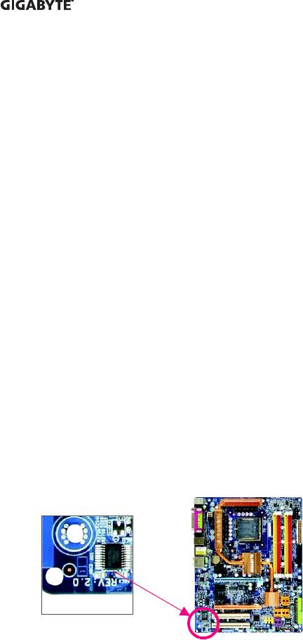
Identifying Your Motherboard Revision
The revision number on your motherboard looks like this: «REV: X.X.» For example, «REV: 1.0»
means the revision of the motherboard is 1.0. Check your motherboard revision before updating
motherboard BIOS, drivers, or when looking for technical information.
Example:

Table of Contents
Box Contents ………………………………………………………………………………………………….. 6
Optional Items ………………………………………………………………………………………………….. 6
GA-945GCM-S2L/GA-945GCM-S2C Motherboard Layout…………………………………….. 7
Block Diagram…………………………………………………………………………………………………. 8
Chapter 1 Hardware Installation ………………………………………………………………………… 9
1—1 Installation Precautions …………………………………………………………………………. 9
1—2 Product Specifications ………………………………………………………………………… 10
1—3 Installing the CPU and CPU Cooler…………………………………………………….. 13
1-3-1 Installing the CPU …………………………………………………………………………………… 13
1-3-2 Installing the CPU Cooler ……………………………………………………………………….. 15
1-4 Installing the Memory …………………………………………………………………………. 16
1-4-1 Dual Channel Memory Configuration………………………………………………………. 16
1-4-2 Installing a Memory………………………………………………………………………………… 17
1-5 Installing an Expansion Card ………………………………………………………………. 18
1-6 Back Panel Connectors ……………………………………………………………………… 19
1—7 Internal Connectors …..……………………………………………………………………….. 21
Chapter 2 BIOS Setup……………………………………………………………………………………. 31
2—1 Startup Screen …………………………………………………………………………………… 32
2-2 The Main Menu …………………………………………………………………………………. 33
2-3 Standard CMOS Features ………………………………………………………………….. 35
2—4 Advanced BIOS Features…………………………………………………………………… 37
2-5 Integrated Peripherals …………………………………………………………………………. 39
2-6 Power Management Setup ………………………………………………………………….. 43
2—7 PnP/PCI Configurations……………………………………………………………………… 45
2-8 PC Health Status ………………………………………………………………………………. 46
2—9 Frequency/Voltage Control ………………………………………………………………….. 48
2-10 Load Fail-Safe Defaults……………………………………………………………………….. 50
2—11 Load Optimized Defaults ……………………………………………………………………… 50
2-12 Set Supervisor/User Password…………………………………………………………… 51
2-13 Save & Exit Setup…………………………………………………………………………….. 52
2-14 Exit Without Saving …………………………………………………………………………… 52
— 4 —

Chapter 3 Drivers Installation ………………………………………………………………………….. 53
3-1 Installing Chipset Drivers ……………………………………………………………………. 53
3—2 Software Applications …………………………………………………………………………. 54
3-3 Driver CD Information ………………………………………………………………………… 54
3—4 Hardware Information …………………………………………………………………………. 55
3—5 Contact Us……………………………………………………………………………………….. 55
Chapter 4 Unique Features…………………………………………………………………………….. 57
4-1 Xpress Recovery2 …………………………………………………………………………….. 57
4—2 BIOS Update Utilities…………………………………………………………………………. 62
4-2-1 Updating the BIOS with the Q-Flash Utility……………………………………………… 62
4-2-2 Updating the BIOS with the @BIOS Utility ………………………………………………. 65
4-3 EasyTune 5………………………………………………………………………………………. 67
4-4 Windows Vista ReadyBoost………………………………………………………………… 68
Chapter 5 Appendix ………………………………………………………………………………………. 69
5—1 Configuring Audio Input and Output……………………………………………………….. 69
5-1-1 Configuring 2/4/5.1-Channel Audio…………………………………………………………. 69
5-1-2 Installing the S/PDIFOut Cable (Optional) ………………………………………………… 72
5-1-3 Configuring Microphone Recording …………………………………………………………. 74
5-1-4 Using the Sound Recorder……………………………………………………………………… 76
5-2 Troubleshooting ………………………………………………………………………………….. 77
5-2-1 Frequently Asked Questions ………………………………………………………………….. 77
5-2-2 Troubleshooting Procedure …………………………………………………………………….. 78
Regulatory Statements ……………………………………………………………………………………. 80
— 5 —
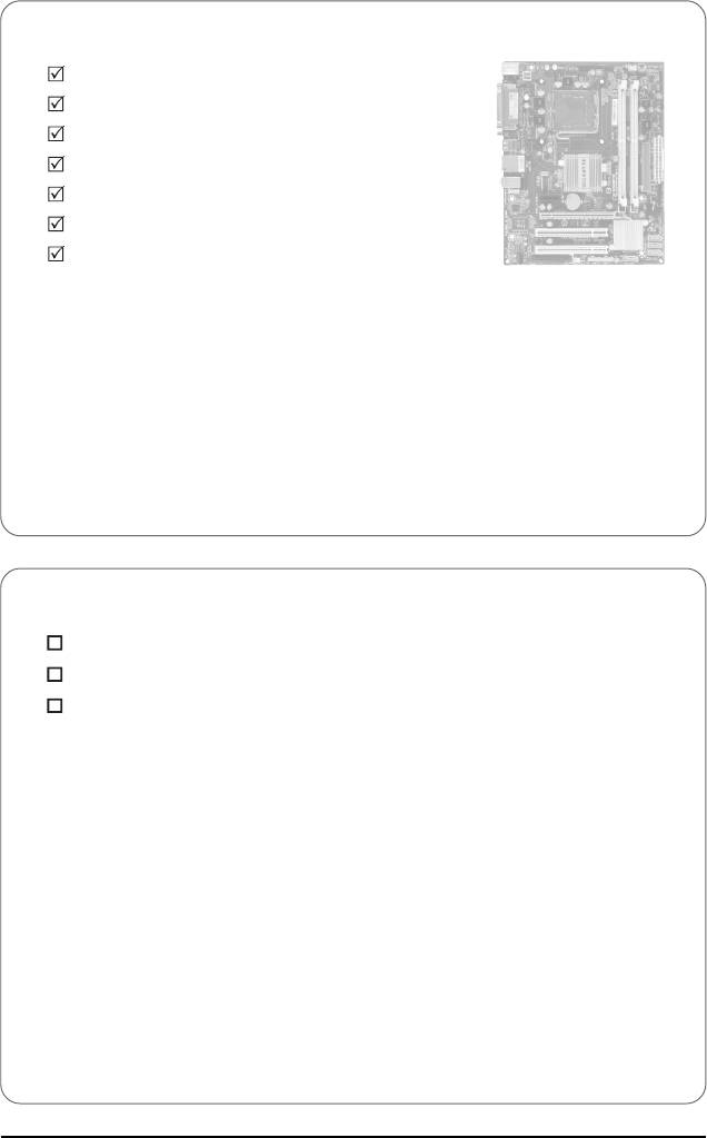
Box Contents
GA-945GCM-S2L or GA-945GCM-S2C motherboard
Motherboard driver disk
User’s Manual
Quick Installation Guide
One IDE cable and one floppy disk drive cable
Two SATA 3Gb/s cables
I/O Shield
• The box contents above are for reference only and the actual items shall depend on product package you obtain.
The box contents are subject to change without notice.
• The motherboard image is for reference only.
Optional Items
2-port USB 2.0 bracket (Part No. 12CR1-1UB030-51R)
2-port SATA power cable (Part No. 12CF1-2SERPW-01R)
S/PDIF out cable (Part No. 12CR1-1SPOUT-02R)
— 6 —
(скачивание инструкции бесплатно)
Формат файла: PDF
Доступность: Бесплатно как и все руководства на сайте. Без регистрации и SMS.
Дополнительно: Чтение инструкции онлайн

GA-945GCM-S2L/
GA-945GCM-S2C
LGA775 socket motherboard for Intel
®
Core
TM
processor family/
Intel
®
Pentium
®
processor family/Intel
®
Celeron
®
processor family
User’s Manual
Rev. 1007
12ME-945GCMS2-1007R
Страница:
(1 из 84)
навигация

1

2

3

4

5

6

7

8

9

10

11

12

13

14

15

16

17

18

19

20

21

22

23

24

25

26

27

28

29

30

31

32

33

34

35

36

37

38

39

40

41

42

43

44

45

46

47

48

49

50

51

52

53

54

55

56

57

58

59

60

61

62

63

64

65

66

67

68

69

70

71

72

73

74

75

76

77

78

79

80

81

82

83

84
Инструкции и руководства похожие на GIGABYTE GA-945GCM-S2L, GA-945GCM-S2C
Другие инструкции и руководства из категории Материнская плата
© 2023 manuals-help.ru, Все права защищены
Посмотреть инструкция для Gigabyte GA-945GCM-S2L бесплатно. Руководство относится к категории Материнские платы, 1 человек(а) дали ему среднюю оценку 7.5. Руководство доступно на следующих языках: английский. У вас есть вопрос о Gigabyte GA-945GCM-S2L или вам нужна помощь? Задайте свой вопрос здесь
Не можете найти ответ на свой вопрос в руководстве? Вы можете найти ответ на свой вопрос ниже, в разделе часто задаваемых вопросов о Gigabyte GA-945GCM-S2L.
Какая ширина Gigabyte GA-945GCM-S2L?
Какая толщина Gigabyte GA-945GCM-S2L?
Инструкция Gigabyte GA-945GCM-S2L доступно в русский?
Не нашли свой вопрос? Задайте свой вопрос здесь